EP3536905A1 - Gas turbine disassembling/assembling method, seal plate assembly, and gas turbine rotor - Google Patents
Gas turbine disassembling/assembling method, seal plate assembly, and gas turbine rotor Download PDFInfo
- Publication number
- EP3536905A1 EP3536905A1 EP17881406.7A EP17881406A EP3536905A1 EP 3536905 A1 EP3536905 A1 EP 3536905A1 EP 17881406 A EP17881406 A EP 17881406A EP 3536905 A1 EP3536905 A1 EP 3536905A1
- Authority
- EP
- European Patent Office
- Prior art keywords
- seal plate
- restraint
- state
- axial direction
- seal
- Prior art date
- Legal status (The legal status is an assumption and is not a legal conclusion. Google has not performed a legal analysis and makes no representation as to the accuracy of the status listed.)
- Granted
Links
Images
















Classifications
-
- F—MECHANICAL ENGINEERING; LIGHTING; HEATING; WEAPONS; BLASTING
- F01—MACHINES OR ENGINES IN GENERAL; ENGINE PLANTS IN GENERAL; STEAM ENGINES
- F01D—NON-POSITIVE DISPLACEMENT MACHINES OR ENGINES, e.g. STEAM TURBINES
- F01D25/00—Component parts, details, or accessories, not provided for in, or of interest apart from, other groups
- F01D25/28—Supporting or mounting arrangements, e.g. for turbine casing
- F01D25/285—Temporary support structures, e.g. for testing, assembling, installing, repairing; Assembly methods using such structures
-
- F—MECHANICAL ENGINEERING; LIGHTING; HEATING; WEAPONS; BLASTING
- F01—MACHINES OR ENGINES IN GENERAL; ENGINE PLANTS IN GENERAL; STEAM ENGINES
- F01D—NON-POSITIVE DISPLACEMENT MACHINES OR ENGINES, e.g. STEAM TURBINES
- F01D11/00—Preventing or minimising internal leakage of working-fluid, e.g. between stages
- F01D11/003—Preventing or minimising internal leakage of working-fluid, e.g. between stages by packing rings; Mechanical seals
-
- F—MECHANICAL ENGINEERING; LIGHTING; HEATING; WEAPONS; BLASTING
- F01—MACHINES OR ENGINES IN GENERAL; ENGINE PLANTS IN GENERAL; STEAM ENGINES
- F01D—NON-POSITIVE DISPLACEMENT MACHINES OR ENGINES, e.g. STEAM TURBINES
- F01D11/00—Preventing or minimising internal leakage of working-fluid, e.g. between stages
- F01D11/005—Sealing means between non relatively rotating elements
- F01D11/006—Sealing the gap between rotor blades or blades and rotor
-
- F—MECHANICAL ENGINEERING; LIGHTING; HEATING; WEAPONS; BLASTING
- F01—MACHINES OR ENGINES IN GENERAL; ENGINE PLANTS IN GENERAL; STEAM ENGINES
- F01D—NON-POSITIVE DISPLACEMENT MACHINES OR ENGINES, e.g. STEAM TURBINES
- F01D25/00—Component parts, details, or accessories, not provided for in, or of interest apart from, other groups
-
- F—MECHANICAL ENGINEERING; LIGHTING; HEATING; WEAPONS; BLASTING
- F01—MACHINES OR ENGINES IN GENERAL; ENGINE PLANTS IN GENERAL; STEAM ENGINES
- F01D—NON-POSITIVE DISPLACEMENT MACHINES OR ENGINES, e.g. STEAM TURBINES
- F01D5/00—Blades; Blade-carrying members; Heating, heat-insulating, cooling or antivibration means on the blades or the members
- F01D5/30—Fixing blades to rotors; Blade roots ; Blade spacers
-
- F—MECHANICAL ENGINEERING; LIGHTING; HEATING; WEAPONS; BLASTING
- F01—MACHINES OR ENGINES IN GENERAL; ENGINE PLANTS IN GENERAL; STEAM ENGINES
- F01D—NON-POSITIVE DISPLACEMENT MACHINES OR ENGINES, e.g. STEAM TURBINES
- F01D5/00—Blades; Blade-carrying members; Heating, heat-insulating, cooling or antivibration means on the blades or the members
- F01D5/30—Fixing blades to rotors; Blade roots ; Blade spacers
- F01D5/3007—Fixing blades to rotors; Blade roots ; Blade spacers of axial insertion type
- F01D5/3015—Fixing blades to rotors; Blade roots ; Blade spacers of axial insertion type with side plates
-
- F—MECHANICAL ENGINEERING; LIGHTING; HEATING; WEAPONS; BLASTING
- F01—MACHINES OR ENGINES IN GENERAL; ENGINE PLANTS IN GENERAL; STEAM ENGINES
- F01D—NON-POSITIVE DISPLACEMENT MACHINES OR ENGINES, e.g. STEAM TURBINES
- F01D5/00—Blades; Blade-carrying members; Heating, heat-insulating, cooling or antivibration means on the blades or the members
- F01D5/30—Fixing blades to rotors; Blade roots ; Blade spacers
- F01D5/3053—Fixing blades to rotors; Blade roots ; Blade spacers by means of pins
-
- F—MECHANICAL ENGINEERING; LIGHTING; HEATING; WEAPONS; BLASTING
- F01—MACHINES OR ENGINES IN GENERAL; ENGINE PLANTS IN GENERAL; STEAM ENGINES
- F01D—NON-POSITIVE DISPLACEMENT MACHINES OR ENGINES, e.g. STEAM TURBINES
- F01D5/00—Blades; Blade-carrying members; Heating, heat-insulating, cooling or antivibration means on the blades or the members
- F01D5/30—Fixing blades to rotors; Blade roots ; Blade spacers
- F01D5/32—Locking, e.g. by final locking blades or keys
-
- F—MECHANICAL ENGINEERING; LIGHTING; HEATING; WEAPONS; BLASTING
- F01—MACHINES OR ENGINES IN GENERAL; ENGINE PLANTS IN GENERAL; STEAM ENGINES
- F01D—NON-POSITIVE DISPLACEMENT MACHINES OR ENGINES, e.g. STEAM TURBINES
- F01D5/00—Blades; Blade-carrying members; Heating, heat-insulating, cooling or antivibration means on the blades or the members
- F01D5/30—Fixing blades to rotors; Blade roots ; Blade spacers
- F01D5/32—Locking, e.g. by final locking blades or keys
- F01D5/323—Locking of axial insertion type blades by means of a key or the like parallel to the axis of the rotor
-
- F—MECHANICAL ENGINEERING; LIGHTING; HEATING; WEAPONS; BLASTING
- F01—MACHINES OR ENGINES IN GENERAL; ENGINE PLANTS IN GENERAL; STEAM ENGINES
- F01D—NON-POSITIVE DISPLACEMENT MACHINES OR ENGINES, e.g. STEAM TURBINES
- F01D5/00—Blades; Blade-carrying members; Heating, heat-insulating, cooling or antivibration means on the blades or the members
- F01D5/30—Fixing blades to rotors; Blade roots ; Blade spacers
- F01D5/32—Locking, e.g. by final locking blades or keys
- F01D5/326—Locking of axial insertion type blades by other means
-
- F—MECHANICAL ENGINEERING; LIGHTING; HEATING; WEAPONS; BLASTING
- F01—MACHINES OR ENGINES IN GENERAL; ENGINE PLANTS IN GENERAL; STEAM ENGINES
- F01D—NON-POSITIVE DISPLACEMENT MACHINES OR ENGINES, e.g. STEAM TURBINES
- F01D25/00—Component parts, details, or accessories, not provided for in, or of interest apart from, other groups
- F01D25/28—Supporting or mounting arrangements, e.g. for turbine casing
-
- F—MECHANICAL ENGINEERING; LIGHTING; HEATING; WEAPONS; BLASTING
- F05—INDEXING SCHEMES RELATING TO ENGINES OR PUMPS IN VARIOUS SUBCLASSES OF CLASSES F01-F04
- F05D—INDEXING SCHEME FOR ASPECTS RELATING TO NON-POSITIVE-DISPLACEMENT MACHINES OR ENGINES, GAS-TURBINES OR JET-PROPULSION PLANTS
- F05D2220/00—Application
- F05D2220/30—Application in turbines
- F05D2220/32—Application in turbines in gas turbines
-
- F—MECHANICAL ENGINEERING; LIGHTING; HEATING; WEAPONS; BLASTING
- F05—INDEXING SCHEMES RELATING TO ENGINES OR PUMPS IN VARIOUS SUBCLASSES OF CLASSES F01-F04
- F05D—INDEXING SCHEME FOR ASPECTS RELATING TO NON-POSITIVE-DISPLACEMENT MACHINES OR ENGINES, GAS-TURBINES OR JET-PROPULSION PLANTS
- F05D2230/00—Manufacture
- F05D2230/60—Assembly methods
-
- F—MECHANICAL ENGINEERING; LIGHTING; HEATING; WEAPONS; BLASTING
- F05—INDEXING SCHEMES RELATING TO ENGINES OR PUMPS IN VARIOUS SUBCLASSES OF CLASSES F01-F04
- F05D—INDEXING SCHEME FOR ASPECTS RELATING TO NON-POSITIVE-DISPLACEMENT MACHINES OR ENGINES, GAS-TURBINES OR JET-PROPULSION PLANTS
- F05D2230/00—Manufacture
- F05D2230/60—Assembly methods
- F05D2230/64—Assembly methods using positioning or alignment devices for aligning or centring, e.g. pins
-
- F—MECHANICAL ENGINEERING; LIGHTING; HEATING; WEAPONS; BLASTING
- F05—INDEXING SCHEMES RELATING TO ENGINES OR PUMPS IN VARIOUS SUBCLASSES OF CLASSES F01-F04
- F05D—INDEXING SCHEME FOR ASPECTS RELATING TO NON-POSITIVE-DISPLACEMENT MACHINES OR ENGINES, GAS-TURBINES OR JET-PROPULSION PLANTS
- F05D2230/00—Manufacture
- F05D2230/60—Assembly methods
- F05D2230/68—Assembly methods using auxiliary equipment for lifting or holding
-
- F—MECHANICAL ENGINEERING; LIGHTING; HEATING; WEAPONS; BLASTING
- F05—INDEXING SCHEMES RELATING TO ENGINES OR PUMPS IN VARIOUS SUBCLASSES OF CLASSES F01-F04
- F05D—INDEXING SCHEME FOR ASPECTS RELATING TO NON-POSITIVE-DISPLACEMENT MACHINES OR ENGINES, GAS-TURBINES OR JET-PROPULSION PLANTS
- F05D2230/00—Manufacture
- F05D2230/70—Disassembly methods
-
- F—MECHANICAL ENGINEERING; LIGHTING; HEATING; WEAPONS; BLASTING
- F05—INDEXING SCHEMES RELATING TO ENGINES OR PUMPS IN VARIOUS SUBCLASSES OF CLASSES F01-F04
- F05D—INDEXING SCHEME FOR ASPECTS RELATING TO NON-POSITIVE-DISPLACEMENT MACHINES OR ENGINES, GAS-TURBINES OR JET-PROPULSION PLANTS
- F05D2240/00—Components
- F05D2240/20—Rotors
- F05D2240/24—Rotors for turbines
-
- F—MECHANICAL ENGINEERING; LIGHTING; HEATING; WEAPONS; BLASTING
- F05—INDEXING SCHEMES RELATING TO ENGINES OR PUMPS IN VARIOUS SUBCLASSES OF CLASSES F01-F04
- F05D—INDEXING SCHEME FOR ASPECTS RELATING TO NON-POSITIVE-DISPLACEMENT MACHINES OR ENGINES, GAS-TURBINES OR JET-PROPULSION PLANTS
- F05D2240/00—Components
- F05D2240/20—Rotors
- F05D2240/30—Characteristics of rotor blades, i.e. of any element transforming dynamic fluid energy to or from rotational energy and being attached to a rotor
-
- F—MECHANICAL ENGINEERING; LIGHTING; HEATING; WEAPONS; BLASTING
- F05—INDEXING SCHEMES RELATING TO ENGINES OR PUMPS IN VARIOUS SUBCLASSES OF CLASSES F01-F04
- F05D—INDEXING SCHEME FOR ASPECTS RELATING TO NON-POSITIVE-DISPLACEMENT MACHINES OR ENGINES, GAS-TURBINES OR JET-PROPULSION PLANTS
- F05D2240/00—Components
- F05D2240/80—Platforms for stationary or moving blades
-
- F—MECHANICAL ENGINEERING; LIGHTING; HEATING; WEAPONS; BLASTING
- F05—INDEXING SCHEMES RELATING TO ENGINES OR PUMPS IN VARIOUS SUBCLASSES OF CLASSES F01-F04
- F05D—INDEXING SCHEME FOR ASPECTS RELATING TO NON-POSITIVE-DISPLACEMENT MACHINES OR ENGINES, GAS-TURBINES OR JET-PROPULSION PLANTS
- F05D2260/00—Function
- F05D2260/30—Retaining components in desired mutual position
-
- F—MECHANICAL ENGINEERING; LIGHTING; HEATING; WEAPONS; BLASTING
- F05—INDEXING SCHEMES RELATING TO ENGINES OR PUMPS IN VARIOUS SUBCLASSES OF CLASSES F01-F04
- F05D—INDEXING SCHEME FOR ASPECTS RELATING TO NON-POSITIVE-DISPLACEMENT MACHINES OR ENGINES, GAS-TURBINES OR JET-PROPULSION PLANTS
- F05D2260/00—Function
- F05D2260/30—Retaining components in desired mutual position
- F05D2260/31—Retaining bolts or nuts
Definitions
- the present disclosure relates to a method for disassembling/assembling a gas turbine, a seal plate assembly, and a gas turbine rotor.
- a gas turbine generally includes a gas turbine rotor including a rotor disc, a plurality of blades mounted on an outer peripheral surface of the rotor disc, and at least one seal plate assembly for the blades.
- Patent Document 1 discloses a gas turbine including a seal plate assembly (locking plate assembly) disposed on axially upstream and downstream sides of a rotor disc.
- the upstream seal plate assembly includes a seal plate (locking plate) configured to engage with a blade to restrict movement of the blade in the axial direction, and a seal plate restraint part (eccentric cam) configured to engage with the rotor disc to restrict movement of the seal plate in the radial direction.
- the eccentric cam is held to the seal plate while being in contact with the outer peripheral surface of the rotor disc.
- the eccentric cam When the gas turbine is disassembled or assembled, the eccentric cam is rotated and moved in the radial direction of the rotor disc to switch between a state where the seal plate engages with the blade and a state where the seal plate does not engage with the blade. Further, it is disclosed that the eccentric cam on the upstream side of the rotor disc is rotated, through a space formed between a root portion of the blade and a blade groove of the rotor disc, from the downstream side of the rotor disc.
- Patent Document 1 US Patent Application Publication No. 2006/0073021
- At least one embodiment of the present invention was made in view of the above typical problem, and an object thereof is to provide a method for disassembling/assembling a gas turbine, a seal plate assembly, and a gas turbine rotor including the same whereby it is possible to appropriately switch between the engagement state and the non-engagement between the seal plate and the blade from the opposite side of the rotor disc from the seal plate.
- an expression of a shape such as a rectangular shape or a cylindrical shape shall not be construed as only the geometrically strict shape, but also includes a shape with unevenness or chamfered corners within the range in which the same effect can be achieved.
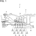
- FIG. 1 is a schematic cross-sectional view of a gas turbine 2 according to an embodiment of the present invention, taken along the rotational axis of the gas turbine 2.
- the axial direction of the gas turbine rotor 16 (axial direction of the rotor disc 18) is referred to as merely “axial direction” or “axially”
- the circumferential direction of the gas turbine rotor 16 (circumferential direction of the rotor disc 18) is referred to as merely “circumferential direction” or “circumferentially”
- the radial direction of the gas turbine rotor 16 (radial direction of the rotor disc 18) is referred to as merely “radial direction” or "radially”.
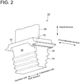
- the blade 22 includes a blade body 28, a platform 30 disposed on an inner side of the blade body 28 in the radial direction, a shank 32 disposed on an inner side of the platform 30 in the radial direction, and a blade root 34 disposed on an inner side of the shank 32 in the radial direction.
- An inner peripheral surface of an axially downstream end portion of the platform 30 has an outer groove 36 recessed outward in the radial direction and extending in the circumferential direction.
- the rotor disc 18 has an inner groove 40 formed downstream of the blade groove 26, recessed inward in the radial direction, and extending in the circumferential direction.
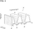
- outer peripheral surface 24 of rotor disc 18 means a surface of the rotor disc 18 in which the blade groove 26 is formed, and does not include a surface in which the inner groove 40 is formed.
- the seal plate 44 has a radially outer end portion 48 configured to be fitted into the outer groove 36 of the blade 22 and thereby engages with the blade 22 to restrict movement of the blade 22 along the axial direction. Further, the outer groove 36 restricts movement of the seal plate 44 in the radial direction to prevent radially outward movement of the seal plate 44.
- the seal plate 44 has a first surface 50 and a second surface 52 which face in opposite directions. The first surface 50 faces upstream in the axial direction, while the second surface 52 faces downstream in the axial direction.
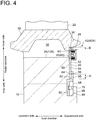
- the seal plate restraint part 46 is configured to be switchable between a seal plate restraint state (see FIG. 4 ) where at least a part of the seal plate restraint part 46 protrudes upstream in the axial direction from the seal plate 44 and thereby restricts movement of the seal plate 44 in the radial direction and a seal plate non-restraint state (see FIG. 5 ) where movement of the seal plate 44 is not restricted in the radial direction.
- the seal plate restraint part 46 is configured as a movable part capable of protruding from the first surface 50 at a variable protruding amount.
- the seal plate restraint part 46 engages with the rotor disc 18 in such a manner that the peripheral surface of the seal plate restraint part 46 is caught on the outer peripheral surface 24 of the rotor disc 18, thereby restricting radially inward movement of the seal plate 44.
- the protruding direction (moving direction) of the seal plate restraint part 46 may not be parallel to the axial direction but includes an axial component.
- the seal plate restraint part 46 may protrude (move) along the extension direction of the blade groove 26.
- An axially downstream end portion of the seal plate restraint part 46 has a male thread 86 configured to be screwed with the female thread 84.
- the seal plate restraint part 46 includes a brim part 88 adjoining the axially upstream side of the male thread 86 and protruding in the radial direction of the male thread 86, and a protruding part 90 protruding upstream in the axial direction from the brim part 88.
- the accommodation chamber forming part 76 includes a brim restraint part 96 disposed upstream of the brim part 88 in the axial direction to restrict axially upstream movement of the brim part 88.
- the opening 78 is provided in the brim restraint part 96, and a part of the protruding part 90 is configured to protrude upstream in the axial direction from the opening 78 in a state where the brim part 88 abuts on the brim restraint part 96.
- the accommodation chamber forming part 76 protrudes downstream in the axial direction from the plate part 72 over a range W1 which is 80% or more of an existence range W0 where the seal plate 44 exists in the circumferential direction.
- the accommodation chamber forming part 76 protrudes downstream uniformly over the entire circumferential range W1 except for a range where the stepped portion 98 is formed on one circumferential side of the downstream surface of the seal plate 44.
- the plurality of seal plate assemblies 42 includes three seal plate assemblies 42 which are adjacent in the circumferential direction and other three seal plate assemblies 42 which are symmetrical to the former three seal plate assemblies 42 with respect to the rotation center O. Further, in an angular range where the six seal plate assemblies 42 are not disposed in the circumferential direction, a plurality of seal plates 110 not provided with the seal plate restraint part 46 are arranged in the circumferential direction.
- FIG. 25 is an enlarged cross-sectional view of the vicinity of a seal plate restraint part 46 (movable part) of a seal plate assembly 42(42D) according to an embodiment, taken along the axial direction.
- the seal plate 44 has a through hole 178 penetrating in the axial direction, and a female thread 184 is formed in the through hole 178.
- the eccentric cam 172 is rotatably supported to the seal plate 44 with a male thread 186 formed in the shaft part 176 being screwed with the female thread 184 of the seal plate 44.
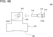
- the inspection device 500 shown in FIGs. 47 and 48 is used to check appropriateness of the assembly state of the seal plate assembly 42 by measuring whether the protrusion amount of the seal plate restraint part 46 of the seal plate assembly 42 from the seal plate 44 is within a predetermined range, as shown in FIG. 49 .
- the inspection device 500 is useful when it is difficult to directly measure the protrusion amount of the seal plate restraint part 46, and the inspection device 500 can be used for the seal plate assemblies 42(42A to 42I), for instance.
- the inspection target is the seal plate assembly 42(42A to 42H) including the seal plate restraint part 46 engaging with the outer peripheral surface 24 of the rotor disc 18, the seal plate assembly 42I can also be inspected by the inspection device 500.
- the inspection device 500 includes an inspection rod 510 and an inspection rod holder 520 for holding the inspection rod 510 in a predetermined orientation.
- the inspection rod 510 is inserted into the holding hole 522 of the inspection rod holder 520, and the inspection rod 510 is pushed into the holding hole 522 until the distal end portion 516 of the inspection rod 510 comes into contact with the seal plate restraint part 46 of the seal plate assembly 42 via the clearance 38.
- the inspection rod 510 is pushed, the enlarged diameter part 518 of the inspection rod 510 is fitted into the enlarged diameter portion 522A of the holding hole 522, so that the orientation of the inspection rod 510 is restricted.
- the distal end portion 516 of the inspection rod 510 may be engaged with the recess (not shown) (e.g., jig engagement portion 92) of the seal plate restraint part 46.
- the position of the measurement reference surface 528 of the inspection rod holder 520 may be set to be positioned between the pair of measurement surfaces 514A, 514B of the inspection rod 510 in a case where the assembly state of the seal plate assembly 42 is appropriate. Thereby, it is possible to easily check the appropriateness of the assembly state of the seal plate assembly 42.
- both the measurement surfaces 514A, 514B are located on a side of the measurement reference surface 528 on which the seal plate assembly 42 is positioned (i.e., if both the measurement surfaces 514A, 514B are located within the holding hole 522), it is determined that the protrusion amount of the seal plate restraint part 46 from the seal plate 44 is insufficient, and the seal plate assembly 42 is not in the appropriate assembly state.
- one measurement surfaces 514A is located on a side of the measurement reference surface 528 opposite the side on which the seal plate assembly 42 is positioned (i.e., the measurement surface 514A is located outside the holding hole 522)
- the other measurement surface 514B is located on the side of the measurement reference surface 528 on which the seal plate assembly 42 is positioned (i.e., the measurement surface 514B is located within the holding hole 522)
Landscapes
- Engineering & Computer Science (AREA)
- Mechanical Engineering (AREA)
- General Engineering & Computer Science (AREA)
- Turbine Rotor Nozzle Sealing (AREA)
Abstract
Description
- The present disclosure relates to a method for disassembling/assembling a gas turbine, a seal plate assembly, and a gas turbine rotor.
- A gas turbine generally includes a gas turbine rotor including a rotor disc, a plurality of blades mounted on an outer peripheral surface of the rotor disc, and at least one seal plate assembly for the blades.
- The seal plate assembly is disposed on at least one axial side of the rotor disc to seal the axial gas flow in a space between blades which are adjacent in the circumferential direction of the rotor disc.
- A gas turbine generally includes a rotor disc, a plurality of blades mounted on an outer peripheral surface of the rotor disc, and at least one seal plate assembly for the blades.
-
Patent Document 1 discloses a gas turbine including a seal plate assembly (locking plate assembly) disposed on axially upstream and downstream sides of a rotor disc. - In the gas turbine according to
Patent Document 1, the upstream seal plate assembly includes a seal plate (locking plate) configured to engage with a blade to restrict movement of the blade in the axial direction, and a seal plate restraint part (eccentric cam) configured to engage with the rotor disc to restrict movement of the seal plate in the radial direction. The eccentric cam is held to the seal plate while being in contact with the outer peripheral surface of the rotor disc. When the eccentric cam rotates, the position of the rotation center of the eccentric cam relative to the outer peripheral surface of the rotor disc changes in accordance with the phase of the eccentric cam, and the seal plate moves in the radial direction of the rotor disc. - When the gas turbine is disassembled or assembled, the eccentric cam is rotated and moved in the radial direction of the rotor disc to switch between a state where the seal plate engages with the blade and a state where the seal plate does not engage with the blade. Further, it is disclosed that the eccentric cam on the upstream side of the rotor disc is rotated, through a space formed between a root portion of the blade and a blade groove of the rotor disc, from the downstream side of the rotor disc.
- Patent Document 1:
US Patent Application Publication No. 2006/0073021 - In the seal plate assembly disclosed in
Patent Document 1, the eccentric cam serving as a seal plate restraint part is disposed on the seal plate so as to protrude away from the rotor disc in the axial direction (protrude upstream in Patent Document 1), and the peripheral surface of this protruding portion engages with a protrusion of the rotor disc, so that the seal plate is restrained in the radial direction. - In the above configuration, in a case where the eccentric cam is operated from the opposite side of the rotor disc from the seal plate in the axial direction (downstream side in Patent Document 1) to disassemble or assemble the gas turbine, a portion of the eccentric cam engaged with the protrusion cannot be visually recognized, and the eccentric cam cannot be rotated while recognizing the phase of the eccentric cam.
- Thus, it is not easy to appropriately switch between the engagement state and the non-engagement state between the seal plate and the blade from the opposite side of the rotor disc from the seal plate.
- At least one embodiment of the present invention was made in view of the above typical problem, and an object thereof is to provide a method for disassembling/assembling a gas turbine, a seal plate assembly, and a gas turbine rotor including the same whereby it is possible to appropriately switch between the engagement state and the non-engagement between the seal plate and the blade from the opposite side of the rotor disc from the seal plate.
-
- (1) According to at least one embodiment of the present invention, a method for disassembling/assembling a gas turbine including a seal plate disposed on a first side of a rotor disc in an axial direction of the rotor disc and a seal plate restraint part for restricting movement of the seal plate relative to the rotor disc in a radial direction of the rotor disc comprises a seal-plate-restraint-state switching step of operating the seal plate restraint part from a second side in the axial direction to switch between a seal plate non-restraint state where the seal plate restraint part does not restrict movement of the seal plate in the radial direction and a seal plate restraint state where at least a part of the seal plate restraint part protrudes toward the second side in the axial direction from the seal plate and thereby restricts movement of the seal plate in the radial direction.
With the method for disassembling/assembling a gas turbine described in the above (1), in the seal-plate-restraint-state switching step, the seal plate non-restraint state and the seal plate restraint state are switched by operating the seal plate restraint part from the second side in the axial direction, i.e., from a side on which the seal plate restraint part protrudes from the seal plate (side closer to the rotor disc than the seal plate is in axial direction).
Thus, it is possible to switch between the seal plate restraint state and the seal plate non-restraint state from the opposite side of the rotor disc from the seal plate, while visually recognizing whether the seal plate restraint part is in the seal plate restraint state or the seal plate non-restraint state, when disassembling or assembling the gas turbine. Thus, it is easy to appropriately switch between the seal plate restraint state and the seal plate non-restraint state from the opposite side of the rotor disc from the seal plate.
Consequently, it is easy to appropriately switch between the engagement state and the non-engagement state between the seal plate and the blade from the opposite side of the rotor disc from the seal plate, when disassembling or assembling the gas turbine. - (2) In some embodiments, in the method for disassembling/assembling a gas turbine described in the above (1), the first side in the axial direction is a downstream side of a combustion gas flow in the axial direction, and the second side in the axial direction is an upstream side of the combustion gas flow in the axial direction.
With the method for disassembling/assembling a gas turbine described in the above (2), it is possible to switch between the seal plate restraint state and the seal plate non-restraint state in the seal plate assembly disposed downstream of the rotor disc, from the upstream side of the rotor disc, while visually recognizing whether the seal plate restraint part is in the seal plate restraint state or the seal plate non-restraint state, when disassembling or assembling the gas turbine. Thus, it is possible to easily and appropriately switch between the seal plate restraint state and the seal plate non-restraint state of the seal plate assembly disposed downstream of the rotor disc from the upstream side of the rotor disc.
Consequently, it is easy to appropriately switch between the engagement state and the non-engagement state between the seal plate and the blade in the seal plate assembly disposed downstream of the rotor disc, from the upstream side of the rotor disc, when disassembling or assembling the gas turbine.
Further, in a case where a casing of the gas turbine has an opening (e.g., opening for attaching combustor or entrance for operators) on the upstream side of the rotor disc, it is possible to attach or remove the blade with respect to the rotor disc, without removing the casing of the gas turbine, from the upstream side of the rotor disc. Thus, it is possible to improve maintenance performance of the gas turbine. - (3) In some embodiments, in the method for disassembling/assembling a gas turbine described in the above (1) or (2), the seal-plate-restraint-state switching step includes operating the seal plate restraint part through a space between two adjacent blades, on a radially inner side of platforms of the two blades, to switch between the seal plate non-restraint state and the seal plate restraint state.
With the method for disassembling/assembling a gas turbine described in the above (3), in some cases, a relatively wide space is ensured between two adjacent blades, on the radially inner side of the platforms of the two blades, for a reason described later. Thus, it is possible to easily switch between the seal plate non-restraint state and the seal plate restraint state by operating the seal plate restraint part through the relatively wide space. - (4) In some embodiments, in the method for disassembling/assembling a gas turbine described in any one of the above (1) to (3), the rotor disc includes a through hole extending along the axial direction, and the seal-plate-restraint-state switching step includes operating the seal plate restraint part via the through hole to switch between the seal plate non-restraint state and the seal plate restraint state.
- (5) In some embodiments, in the method for disassembling/assembling a gas turbine described in any one of the above (1) to (4), the seal-plate-restraint-state switching step includes switching between a state where the seal plate restraint part does not engage with the rotor disc and a state where the seal plate restraint part engages with the rotor disc by moving the seal plate restraint part along the axial direction to switch between the seal plate non-restraint state and the seal plate restraint state.
With the method for disassembling/assembling a gas turbine described in the above (5), in the seal-plate-restraint-state switching step, the seal plate non-restraint state and the seal plate restraint state are switched by moving the seal plate restraint part along the axial direction.
Thus, for instance, even if force acts on the seal plate restraint part in a direction different from the axial direction of the seal plate restraint part by friction caused between the outer peripheral surface of the rotor disc and the seal plate restraint part due to vibration during turning of the gas turbine rotor, or due to acceleration or deceleration of rotation of the rotor disc during turning of the gas turbine rotor, the seal plate non-restraint state and the seal plate restraint state are not easily switched.
Thus, it is possible to control switching between the engagement state and the non-engagement state between the seal plate and the blade at an unintended timing.
Further, since the seal plate non-restraint state and the seal plate restraint state are switched by switching between the engagement state and the non-engagement state between the seal plate restraint part and the rotor disc, it is possible to enhance the effect of controlling switching between the engagement state and the non-engagement state between the seal plate and the blade at an unintended timing. - (6) In some embodiments, in the method for disassembling/assembling a gas turbine described in any one of the above (1) to (5), the seal-plate-restraint-state switching step includes moving the seal plate restraint part between a position where the seal plate restraint part and the rotor disc do not overlap in the axial direction and a position where the seal plate restraint part and the rotor disc overlap in the axial direction to switch between the seal plate non-restraint state and the seal plate restraint state.
With the method for disassembling/assembling a gas turbine described in the above (6), it is possible to enhance the effect of controlling switching between the engagement state and the non-engagement state between the seal plate and the blade at an unintended timing. - (7) In some embodiments, in the method for disassembling/assembling a gas turbine described in any one of the above (1) to (6), the seal-plate-restraint-state switching step includes rotating the seal plate restraint part while one of a female thread or a male thread provided in the seal plate restraint part is screwed with the other of the female thread or the male thread provided in the seal plate to switch between the seal plate non-restraint state and the seal plate restraint state.
With the method for disassembling/assembling a gas turbine described in the above (7), since the seal plate non-restraint state and the seal plate restraint state are switched by rotating the seal plate restraint part while the male thread is screwed with the female thread, even if force acts on the seal plate restraint part in the axial direction, the seal plate non-restraint state and the seal plate restraint state are not easily switched. Thus, it is possible to enhance the effect of controlling switching between the engagement state and the non-engagement state between the seal plate and the blade at an unintended timing.
Further, since the seal plate non-restraint state and the seal plate restraint state are not switched unless the seal plate restraint part is rotated, it is easy to move the seal plate in the radial direction while keeping the seal plate non-restraint state, for instance. - (8) In some embodiments, in the method for disassembling/assembling a gas turbine described in any one of the above (1) to (7), the seal-plate-restraint-state switching step includes moving the seal plate restraint part along the axial direction against a biasing force of a biasing part biasing the seal plate restraint part to switch from the seal plate restraint state to the seal plate non-restraint state.
With the method for disassembling/assembling a gas turbine described in the above (8), even if a weaker force than the biasing force of the biasing part acts on the seal plate restraint part, the seal plate restraint state is not switched to the seal plate non-restraint state. Thus, it is possible to enhance the effect of controlling switching between the engagement state and the non-engagement state between the seal plate and the blade at an unintended timing.
Further, in a case where the method for disassembling/assembling a gas turbine described in the above (8) is the disassembling/assembling method described in the above (7), the biasing force of the biasing part reduces loosening of the thread. Thus, also for this reason, it is possible to enhance the effect of controlling switching between the engagement state and the non-engagement state between the seal plate and the blade at an unintended timing. - (9) In some embodiments, in the method for disassembling/assembling a gas turbine described in any one of the above (1) to (4), the seal-plate-restraint-state switching step includes switching between a state where the seal plate restraint part does not engage with the seal plate and a state where the seal plate restraint part engages with the seal plate to switch between the seal plate non-restraint state and the seal plate restraint state.
With the method for disassembling/assembling a gas turbine described in the above (9), since the seal plate non-restraint state and the seal plate restraint state are switched by switching between the engagement state and the non-engagement state between the seal plate restraint part and the seal plate, it is possible to enhance the effect of controlling switching between the engagement state and the non-engagement state between the seal plate and the blade at an unintended timing. - (10) In some embodiments, in the method for disassembling/assembling a gas turbine described in the above (9), the seal plate restraint part is a seal plate fall prevention pin extending along the axial direction, and the seal-plate-restraint-state switching step includes switching between a state where a leading end of the seal plate fall prevention pin does not engage with a recess formed in the seal plate and a state where the leading end of the seal plate fall prevention pin engages with the recess formed in the seal plate to switch between the seal plate non-restraint state and the seal plate restraint state.
With the method for disassembling/assembling a gas turbine described in the above (10), since the seal plate non-restraint state and the seal plate restraint state are switched by moving the seal plate fall prevention pin linearly relative to the recess along the axis of the recess, it is possible to easily switch between the seal plate non-restraint state and the seal plate restraint state. - (11) In some embodiments, in the method for disassembling/assembling a gas turbine described in the above (9), the seal plate restraint part is a seal plate fall prevention piece, and the seal-plate-restraint-state switching step includes removing the seal plate fall prevention piece mounted in a recess formed in the seal plate from the recess, or mounting the seal plate fall prevention piece in the recess, to switch between the seal plate non-restraint state and the seal plate restraint state.
With the method for disassembling/assembling a gas turbine described in the above (11), since the seal plate non-restraint state and the seal plate restraint state are switched by removing or mounting the seal plate fall prevention piece from or to the recess of the seal plate, it is possible to easily switch between the seal plate non-restraint state and the seal plate restraint state. - (12) In some embodiments, in the method for disassembling/assembling a gas turbine described in the above (9), the seal-plate-restraint-state switching step includes rotating the seal plate restraint part while a female thread provided in the rotor disc is screwed with a male thread provided in the seal plate restraint part to switch between the seal plate non-restraint state and the seal plate non-restraint state.
With the method for disassembling/assembling a gas turbine described in the above (12), since the seal plate non-restraint state and the seal plate restraint state are switched by rotating the seal plate restraint part while the male thread is screwed with the female thread, even if force acts on the seal plate restraint part in the axial direction, the seal plate non-restraint state and the seal plate restraint state are not easily switched. Thus, it is possible to enhance the effect of controlling switching between the engagement state and the non-engagement state between the seal plate and the blade at an unintended timing.
Further, since the seal plate non-restraint state and the seal plate restraint state are not switched unless the seal plate restraint part is rotated, it is easy to move the seal plate in the radial direction while keeping the seal plate non-restraint state, for instance. - (13) In some embodiments, in the method for disassembling/assembling a gas turbine described in any one of the above (1) to (6), the seal plate and the seal plate restraint part are formed integrally, and the seal-plate-restraint-state switching step includes plastically deforming the seal plate restraint part to switch between the seal plate non-restraint state and the seal plate restraint state.
With the method for disassembling/assembling a gas turbine described in the above (13), since the seal plate non-restraint state and the seal plate restraint state are switched by plastic deformation of the seal plate restraint part, it is possible to easily switch between the seal plate non-restraint state and the seal plate restraint state of the seal plate assembly with a simple configuration. - (14) In some embodiments, in the method for disassembling/assembling a gas turbine described in any one of the above (1) to (6), the seal-plate-restraint-state switching step includes rotating the seal plate restraint part while a male thread provided in the seal plate restraint part is screwed with a female thread provided in a through hole penetrating the seal plate to switch between the seal plate non-restraint state and the seal plate restraint state.
With the method for disassembling/assembling a gas turbine described in the above (14), since the seal plate non-restraint state and the seal plate restraint state are switched by rotating the seal plate restraint part while the male thread is screwed with the female thread, even if force acts on the seal plate restraint part in the axial direction, the seal plate non-restraint state and the seal plate restraint state are not easily switched. Thus, it is possible to enhance the effect of controlling switching between the engagement state and the non-engagement state between the seal plate and the blade at an unintended timing.
Further, since the seal plate non-restraint state and the seal plate restraint state are not switched unless the seal plate restraint part is rotated, it is easy to move the seal plate in the radial direction while keeping the seal plate non-restraint state, for instance. - (15) In some embodiments, in the method for disassembling/assembling a gas turbine described in any one of the above (1) to (14), the method further comprises a blade-restraint-state switching step of moving the seal plate in the radial direction to switch between a blade non-restraint state where the seal plate does not restrict movement of a blade along the axial direction and a blade restraint state where the seal plate restraint part restricts movement of the blade along the axial direction.
With the method for disassembling/assembling a gas turbine described in the above (15), since the seal-plate-restraint-state switching step described in the above (1) is included, it is easy to appropriately switch between the seal plate restraint state and the seal plate non-restraint state from the opposite side of the rotor disc from the seal plate. Thus, it is easy to appropriately switch between the blade non-restraint state and the blade restraint state from the opposite side of the rotor disc from the seal plate, when disassembling or assembling the gas turbine. - (16) In some embodiments, in the method for disassembling/assembling a gas turbine described in the above (15), a jig engagement recess or a jig engagement protrusion capable of engaging with a jig is formed in a surface of the seal plate which faces toward the second side in the axial direction, and the blade-restraint-state switching step includes moving the seal plate in the radial direction while the jig engagement recess or the jig engagement protrusion engages with the jig to switch between the blade non-restraint state and the blade restraint state.
With the method for disassembling/assembling a gas turbine described in the above (16), in the blade-restraint-state switching step, the seal plate can be easily moved in the radial direction by the jig. Thus, it is easy to appropriately switch between the blade non-restraint state and the blade restraint state from the opposite side of the rotor disc from the seal plate, when disassembling or assembling the gas turbine. - (17) In some embodiments, in the method for disassembling/assembling a gas turbine described in the above (15) or (16), the method further comprises a blade-fitting-state switching step of switching a blade non-fitting state where the blade is not fitted in the rotor disc and a blade fitting state where the blade is fitted in the rotor disc.
With the method for disassembling/assembling a gas turbine described in the above (17), it is possible to easily and appropriately switch between the blade restraint state where the seal plate restricts movement of the blade along the axial direction and the blade non-fitting state where the blade is not fitted in the rotor disc, only by operation on the opposite side of the rotor disc from the seal plate. - (18) According to at least one embodiment of the present invention, a seal plate assembly for a blade of a gas turbine comprises: a seal plate configured to be disposed on a first side of a rotor disc in an axial direction of the rotor disc; and a seal plate restraint part for restricting movement of the seal plate relative to the rotor disc in a radial direction of the rotor disc. The seal plate restraint part is configured to be switchable between a seal plate restraint state where at least a part of the seal plate restraint part protrudes toward a second side in the axial direction from the seal plate and thereby restricts movement of the seal plate in the radial direction and a seal plate non-restraint state where movement of the seal plate in the radial direction is not restricted.
With the seal plate assembly described in the above (18), it is possible to switch between the seal plate non-restraint state and the seal plate restraint state by operating the seal plate restraint part from the second side in the axial direction, i.e., from a side on which the seal plate restraint part protrudes from the seal plate (side closer to the rotor disc than the seal plate is in axial direction).
Thus, it is possible to switch between the seal plate restraint state and the seal plate non-restraint state from the opposite side of the rotor disc from the seal plate, while visually recognizing whether the seal plate restraint part is in the seal plate restraint state or the seal plate non-restraint state, when disassembling or assembling the gas turbine. Thus, it is easy to appropriately switch between the seal plate restraint state and the seal plate non-restraint state from the opposite side of the rotor disc from the seal plate.
Consequently, it is easy to appropriately switch between the engagement state and the non-engagement state between the seal plate and the blade from the opposite side of the rotor disc from the seal plate, when disassembling or assembling the gas turbine. - (19) In some embodiments, in the seal plate assembly described in the above (18), the first side in the axial direction is a downstream side in the axial direction, and the second side in the axial direction is an upstream side in the axial direction.
With the seal plate assembly described in the above (19), it is possible to switch between the seal plate restraint state and the seal plate non-restraint state in the seal plate assembly disposed downstream of the rotor disc, from the upstream side of the rotor disc, while visually recognizing whether the seal plate restraint part is in the seal plate restraint state or the seal plate non-restraint state, when disassembling or assembling the gas turbine. Thus, it is possible to easily and appropriately switch between the seal plate restraint state and the seal plate non-restraint state of the seal plate assembly disposed downstream of the rotor disc from the upstream side of the rotor disc.
Consequently, it is easy to appropriately switch between the engagement state and the non-engagement state between the seal plate and the blade in the seal plate assembly disposed downstream of the rotor disc, from the upstream side of the rotor disc, when disassembling or assembling the gas turbine.
Further, in a case where a casing of the gas turbine has an opening on the upstream side of the rotor disc, it is possible to fix or remove the blade with respect to the rotor disc, without removing the casing of the gas turbine. Thus, it is possible to improve maintenance performance of the gas turbine. - (20) In some embodiments, in the seal plate assembly described in the above (18) or (19), the seal plate includes one of a female thread or a male thread extending along the axial direction, and the seal plate restraint part includes the other of the female thread or the male thread which is screwed with the one of the female thread or the male thread.
With the seal plate assembly described in the above (20), since the seal plate non-restraint state and the seal plate restraint state are switched by rotating the seal plate restraint part while the male thread is screwed with the female thread, even if force acts on the seal plate restraint part in the axial direction, the seal plate non-restraint state and the seal plate restraint state are not easily switched. Thus, it is possible to enhance the effect of controlling switching between the engagement state and the non-engagement state between the seal plate and the blade at an unintended timing.
Further, since the seal plate non-restraint state and the seal plate restraint state are not switched unless the seal plate restraint part is rotated, it is easy to move the seal plate in the radial direction while keeping the seal plate non-restraint state, for instance. - (21) In some embodiments, the seal plate assembly described in the above (20) further comprises a washer disposed between the seal plate restraint part and the seal plate.
With the seal plate assembly described in the above (21), loosening of the thread is reduced by the washer. Thus, it is possible to enhance the effect of controlling switching between the engagement state and the non-engagement state between the seal plate and the blade at an unintended timing. - (22) In some embodiments, in the seal plate assembly described in any one of the above (18) to (21), an end portion of the seal plate restraint part on the second side in the axial direction has a jig engagement portion capable of engaging with a jig for rotating the seal plate restraint part.
With the seal plate assembly described in the above (22), by engaging a jig with the jig engagement portion and thereby rotating the seal plate restraint part, it is possible to switch between the seal plate non-restraint state and the seal plate restraint state. - (23) In some embodiments, the seal plate assembly described in any one of the above (18) to (22) further comprises a biasing part biasing the seal plate restraint part toward the second side in the axial direction.
With the seal plate assembly described in the above (23), even if a weaker force than the biasing force of the biasing part acts on the seal plate restraint part, the seal plate restraint state is not switched to the seal plate non-restraint state. Thus, it is possible to enhance the effect of controlling switching between the engagement state and the non-engagement state between the seal plate and the blade at an unintended timing.
Further, in a case where the seal plate assembly described in the above (23) is the seal plate assembly described in the above (20), the biasing force of the biasing part reduces loosening of the thread. Thus, also for this reason, it is possible to enhance the effect of controlling switching between the engagement state and the non-engagement state between the seal plate and the blade at an unintended timing. - (24) In some embodiments, in the seal plate assembly described in the above (23), the biasing part includes a disc spring, a coil spring, or a leaf spring.
With the seal plate assembly described in the above (24), in case of using the disc spring as the biasing part, even if cracks occur in the biasing part, the axial size of the biasing part is not likely to become small. Thus, it is possible to bias the seal plate restraint part relatively stably. - (25) In some embodiments, in the seal plate assembly described in any one of the above (18) to (24), the seal plate includes a plate part extending in the radial direction and an accommodation chamber forming part forming an accommodation chamber for at least partially accommodating the seal plate restraint part, and the seal plate restraint part is configured so that at least a part of the seal plate restraint part is capable of protruding from an opening formed in the accommodation chamber forming part on the second side in the axial direction.
With the seal plate assembly described in the above (25), since the accommodation chamber forming part for at least partially accommodating the seal plate restraint part is provided, it is possible to achieve the effects of the seal plate assembly described in any one of the above (18) to (24) while suppressing the reduction in seal performance of the seal plate. - (26) In some embodiments, in the seal plate assembly described in the above (25), the accommodation chamber forming part protrudes toward the first side in the axial direction from the plate part.
With the seal plate assembly described in the above (26), it is possible to achieve the effects of the seal plate assembly described in the above (25) while ensuring a space allowing the seal plate restraint part to move. - (27) In some embodiments, in the seal plate assembly described in the above (26), the accommodation chamber forming part protrudes toward the first side in the axial direction from the plate part in both a range where the seal plate restraint part exists in a circumferential direction of the rotor disc and a range where the seal plate restraint part does not exist in the circumferential direction.
If the accommodation chamber forming part protrudes toward the first side in the axial direction only in a range where the seal plate restraint part exists in the circumferential direction, windage loss occurs due to the protruding portion of the accommodation chamber forming part when the gas turbine rotor rotates in response to operation of the gas turbine, which causes reduction in gas turbine efficiency.
In view of this, as described in the above (27), with the configuration in which the accommodation chamber forming part protrudes in both a range where the seal plate restraint part exists in the circumferential direction and a range where the seal plate restraint part does not exist in the circumferential direction, it is possible to reduce the windage loss. - (28) In some embodiments, in the seal plate assembly described in the above (26) or (27), the accommodation chamber forming part protrudes toward the first side in the axial direction from the plate part over a range of 80% or more of a length of the seal plate in a circumferential direction of the rotor disc.
With the seal plate assembly described in the above (28), since the accommodation chamber forming part protrudes toward the first side from the plate part over most of the range in the circumference direction, it is possible to suppress the increase in windage loss, compared with the case where the accommodation chamber forming part protrudes locally in the range in the circumferential direction. - (29) In some embodiments, in the seal plate assembly described in any one of the above (25) to (28), an end surface of the accommodation chamber forming part on the first side in the axial direction is formed along a plane perpendicular to the axial direction.
With the seal plate assembly described in the above (29), it is possible to enhance the effect of suppressing the increase in windage loss in the seal plate assembly described in any one of the above (25) to (28). - (30) In some embodiments, in the seal plate assembly described in any one of the above (25) to (29), the accommodation chamber forming part is provided in a radially outer portion of the seal plate.
With the seal plate assembly described in the above (30), the center of gravity of the seal plate is located at a radially outer portion. - (31) In some embodiments, in the seal plate assembly described in any one of the above (25) to (30), the accommodation chamber forming part has a thinned portion at a different position from the accommodation chamber.
With the seal plate assembly described in the above (31), it is possible to adjust the stiffness of the seal plate by provision of the thinned portion. By adjusting the stiffness of the seal plate, it is possible to adjust the natural frequency of the blade. By adjusting the natural frequency of the blade, it is possible to suppress the occurrence of resonance of the blade. - (32) In some embodiments, in the seal plate assembly described in any one of the above (25) to (31), the plate part includes two or more portions having different thicknesses.
With the seal plate assembly described in the above (32), it is possible to adjust the stiffness of the seal plate by provision of the two or more portions having different thicknesses. By adjusting the stiffness of the seal plate, it is possible to adjust the natural frequency of the blade. By adjusting the natural frequency of the blade, it is possible to suppress the occurrence of resonance of the blade. - (33) In some embodiments, in the seal plate assembly described in any one of the above (18) to (32), one of the seal plate or the seal plate restraint part includes a cylindrical part extending along the axial direction, a female thread is formed in an inner peripheral surface of the cylindrical part, the other of the seal plate or the seal plate restraint part includes a male thread screwed with the female thread, the seal plate restraint part includes a brim part and a protruding part protruding toward the second side in the axial direction from the brim part, the seal plate assembly further comprises a disc spring disposed on an outer peripheral side of the cylindrical part and configured to bias the brim part toward the second side in the axial direction, and the seal plate includes a brim restraint part disposed on the second side of the brim part in the axial direction to restrict movement of the brim part toward the second side in the axial direction.
With the seal plate assembly described in the above (33), since the seal plate non-restraint state and the seal plate restraint state are switched by rotating the seal plate restraint part while the male thread is screwed with the female thread, even if force acts on the seal plate restraint part in the axial direction, the seal plate non-restraint state and the seal plate restraint state are not easily switched. Thus, it is possible to enhance the effect of controlling switching between the engagement state and the non-engagement state between the seal plate and the blade at an unintended timing.
Further, since the seal plate non-restraint state and the seal plate restraint state are not switched unless the seal plate restraint part is rotated, it is easy to move the seal plate in the radial direction while keeping the seal plate non-restraint state, for instance. Further, even if a weaker force than the biasing force of the biasing part acts on the seal plate restraint part, the seal plate restraint state is not switched to the seal plate non-restraint state. Thus, it is possible to enhance the effect of controlling switching between the engagement state and the non-engagement state between the seal plate and the blade at an unintended timing.
Further, the biasing force of the biasing part reduces loosening of the thread. Thus, also for this reason, it is possible to enhance the effect of controlling switching between the engagement state and the non-engagement state between the seal plate and the blade at an unintended timing. Further, use of the disc spring as the biasing part prevents the axial size of the biasing part from becoming small when cracks occur in the biasing part. Thus, it is possible to bias the seal plate restraint part relatively stably. - (34) In some embodiments, in the seal plate assembly described in any one of the above (18) to (33), a surface of the seal plate which faces toward the second side in the axial direction is provided with at least one slot having a circumferential length in a circumferential direction of the rotor disc and a radial length in the radial direction of the rotor disc, in which the circumferential length is longer than the radial length.
Generally, a blade is inserted into a blade groove extending obliquely with respect to the axial direction of a rotor disc. Accordingly, in case of inserting a rod-like jig into a space formed between the blades on the radially inner side of the platforms of the blades and moving the seal plate in the radial direction by the jig, the slot having the shape described in the above (34) facilitates engagement with the rod-like jig while the rod-like jig is inclined with respect to the surface of the seal plate which faces toward the second side in the axial direction. Thus, it is easy to move the seal plate in the radial direction. - (35) According to at least one embodiment of the present invention, a gas turbine rotor comprises: a rotor disc; a plurality of blades mounted on the rotor disc; and at least one seal plate assembly for the blades. The at least one seal plate assembly includes the seal plate assembly described in any one of the above (18) to (34).
With the gas turbine rotor described in the above (35), since the seal plate assembly described in any one of the above (18) to (34) is included, it is easy to appropriately switch between the engagement state and the non-engagement state between the seal plate and the blade from the opposite side of the rotor disc from the seal plate, when disassembling or assembling the gas turbine. - (36) In some embodiments, the gas turbine rotor described in the above (35) further comprises: a locking plate for holding the seal plate between the locking plate and an end surface of the rotor disc; and a locking piece configured to press the locking plate toward the end surface of the rotor disc.
With the gas turbine rotor described in the above (36), when the engagement state and the non-engagement state between the seal plate and the blade are switched on the side of the seal plate assembly opposite the rotor disc, the switching can be easily performed by mounting or removing the locking piece and the locking plate. - (37) According to at least one embodiment of the present invention, a gas turbine rotor comprises: a rotor disc; a plurality of blades mounted on the rotor disc; and at least one seal plate assembly for the blades. The at least one seal plate assembly includes a pair of seal plate assemblies which are adjacent to each other in a circumferential direction of the rotor disc, and each of the pair of seal plate assemblies is the seal plate assembly described in any one of the above (18) to (34).
With the gas turbine rotor described in the above (37), since the adjacent seal plate assemblies of the pair are the seal plate assemblies described in any one of the above (18) to (34), it is easy to appropriately switch between the engagement state and the non-engagement state between the seal plate and the blade from the opposite side of the rotor disc from the seal plate, in each of the pair of the seal plate assemblies, when disassembling or assembling the gas turbine.
Further, through a space caused by removing a pair of blades corresponding to the pair of seal plate assemblies from the rotor disc, other seal plates at different positions from the pair of seal plate assemblies can be moved in the circumferential direction and thereby can be easily removed from respective blades. Thus, it is possible to efficiently disassemble the gas turbine. - (38) According to at least one embodiment of the present invention, a gas turbine rotor comprises: a rotor disc; a plurality of blades mounted on the rotor disc; and at least one seal plate assembly for the blades. The at least one seal plate assembly includes a plurality of seal plate assemblies arranged symmetrically around a rotation center of the rotor disc, and each of the plurality of seal plate assemblies arranged symmetrically is the seal plate assembly described in any one of the above (18) to (34).
With the gas turbine rotor described in the above (38), since the seal plate assemblies arranged symmetrically around the rotation center of the rotor disc are the seal plate assemblies described in any one of the above (18) to (34), it is easy to appropriately switch between the engagement state and the non-engagement state between the seal plate and the blade from the opposite side of the rotor disc from the seal plate, in each of the plurality of seal plate assemblies, when disassembling or assembling the gas turbine.
Further, through spaces caused by removing a plurality of blades corresponding to the plurality of seal plate assemblies from the rotor disc, other seal plates at different positions from the plurality of seal plate assemblies can be moved in the circumferential direction and thereby can be easily removed from respective blades.
Further, since the spaces caused by removing the plurality of blades corresponding to the plurality of seal plate assemblies from the rotor disc are positioned symmetrically with respect to the rotation center of the rotor disc, it is possible to remove the blades by moving the other seal plates in the circumferential direction a short distance. Thus, it is possible to efficiently disassemble the gas turbine. - (39) According to at least one embodiment of the present invention, a gas turbine comprises: the gas turbine rotor described in any one of the above (35) to (38) and a casing covering the gas turbine rotor.
With the gas turbine described in the above (39), since the gas turbine rotor described in any one of the above (35) to (38) is included, it is easy to appropriately switch between the engagement state and the non-engagement state between the seal plate and the blade from the opposite side of the rotor disc from the seal plate, when disassembling or assembling the gas turbine. - (40) According to at least one embodiment of the present invention, a method for producing a gas turbine including a seal plate disposed on a first side of a rotor disc in an axial direction of the rotor disc and a seal plate restraint part for restricting movement of the seal plate relative to the rotor disc in a radial direction of the rotor disc comprises a seal-plate-restraint-state switching step of operating the seal plate restraint part from a second side in the axial direction to switch from a seal plate non-restraint state where the seal plate restraint part does not restrict movement of the seal plate in the radial direction to a seal plate restraint state where at least a part of the seal plate restraint part protrudes toward the second side in the axial direction from the seal plate and thereby restricts movement of the seal plate in the radial direction.
- With the method for producing a gas turbine described in the above (40), in the seal-plate-restraint-state switching step, the seal plate non-restraint state and the seal plate restraint state are switched by operating the seal plate restraint part from the second side in the axial direction, i.e., from a side on which the seal plate restraint part protrudes from the seal plate (side closer to the rotor disc than the seal plate is in axial direction).
- Thus, it is possible to switch between the seal plate non-restraint state and the seal plate restraint state from the opposite side of the rotor disc from the seal plate, while visually recognizing whether the seal plate restraint part is in the seal plate restraint state or the seal plate non-restraint state, when producing the gas turbine. Thus, it is possible to appropriately switch from the seal plate non-restraint state to the seal plate restraint state from the opposite side of the rotor disc from the seal plate.
- Consequently, it is easy to easily switch between the engagement state and the non-engagement state between the seal plate and the blade from the opposite side of the rotor disc from the seal plate, when producing the gas turbine.
- According to at least one embodiment of the present invention, there is provided a method for disassembling/assembling a gas turbine, a seal plate assembly, and a gas turbine rotor including the same whereby it is possible to appropriately switch between the engagement state and the non-engagement state between the seal plate and the blade from the opposite side of the rotor disc from the seal plate.
-
-
FIG. 1 is a schematic cross-sectional view of agas turbine 2 according to an embodiment of the present invention, taken along the rotational axis of thegas turbine 2. -
FIG. 2 is a schematic configuration diagram of ablade 22. -
FIG. 3 is a schematic configuration diagram of ablade groove 26 formed in an outerperipheral surface 24 of agas turbine rotor 16. -
FIG. 4 is a diagram for describing the configuration of a seal plate assembly 42(42A) according to an embodiment, which shows a partial cross-section of agas turbine rotor 16 taken along the axial direction. -
FIG. 5 is a diagram for describing the configuration of a seal plate assembly 42(42A) according to an embodiment, which shows a partial cross-section of agas turbine rotor 16 taken along the axial direction. -
FIG. 6 is an enlarged cross-sectional view of the vicinity of a sealplate restraint part 46 of a seal plate assembly 42(42A), taken along the axial direction. -
FIG. 7 is a schematic diagram showing the arrangement of a plurality of seal plate assemblies 42(42A), viewed from downstream in the axial direction. -
FIG. 8 is a schematic diagram showing a seal plate assembly 42(42A), viewed from upstream in the axial direction. -
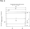
FIG. 9 is a schematic diagram showing a seal plate assembly, viewed from downstream in the axial direction. -
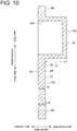
FIG. 10 is a schematic cross-sectional view taken along line A-A inFIG. 8 . -
FIG. 11 is a schematic diagram of aseal plate 110 according to an embodiment, viewed from upstream in the axial direction. -
FIG. 12 is a schematic diagram of theseal plate 110 according to an embodiment, viewed from downstream in the axial direction. -
FIG. 13 is a schematic cross-sectional view taken along line B-B inFIG. 11 . -
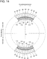
FIG. 14 is a diagram showing the circumferential arrangement ofseal plate assemblies 42 andseal plates 110 in agas turbine rotor 16 according to an embodiment. -
FIG. 15 is a diagram for describing a method for disassembling agas turbine 2 according to an embodiment. -
FIG. 16 is a diagram for describing a method for disassembling agas turbine 2 according to an embodiment. -
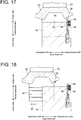
FIG. 17 is a diagram for describing a method for disassembling agas turbine 2 according to an embodiment. -
FIG. 18 is a diagram for describing a method for disassembling agas turbine 2 according to an embodiment. -
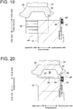
FIG. 19 is a diagram for describing a method for disassembling agas turbine 2 according to an embodiment. -
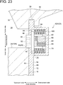
FIG. 20 is a diagram for describing a method for assembling agas turbine 2 according to an embodiment. -
FIG. 21 is a diagram for describing a method for assembling agas turbine 2 according to an embodiment. -
FIG. 22 is a diagram for describing a method for assembling agas turbine 2 according to an embodiment. -
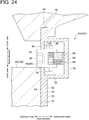
FIG. 23 is an enlarged cross-sectional view of the vicinity of a seal plate restraint part 46 (movable part) of a seal plate assembly 42(42B) according to an embodiment, taken along the axial direction. -
FIG. 24 is an enlarged cross-sectional view of the vicinity of a seal plate restraint part 46 (movable part) of a seal plate assembly 42(42C) according to an embodiment, taken along the axial direction. -
FIG. 25 is an enlarged cross-sectional view of the vicinity of a seal plate restraint part 46 (movable part) of a seal plate assembly 42(42D) according to an embodiment, taken along the axial direction. -
FIG. 26 is an enlarged cross-sectional view of the vicinity of a seal plate restraint part 46 (movable part) of a seal plate assembly 42(42D) according to an embodiment, taken along the axial direction. -
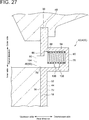
FIG. 27 is an enlarged cross-sectional view of the vicinity of a seal plate restraint part 46 (movable part) of a seal plate assembly 42(42E) according to an embodiment, taken along the axial direction. -
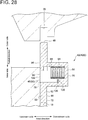
FIG. 28 is an enlarged cross-sectional view of the vicinity of a seal plate restraint part 46 (movable part) of a seal plate assembly 42(42E) according to an embodiment, taken along the axial direction. -
FIG. 29 is an enlarged cross-sectional view of the vicinity of a seal plate restraint part 46 (movable part) of a seal plate assembly 42(42F) according to an embodiment, taken along the axial direction. -
FIG. 30 is an enlarged cross-sectional view of the vicinity of a seal plate restraint part 46 (movable part) of a seal plate assembly 42(42F) according to an embodiment, taken along the axial direction. -
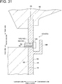
FIG. 31 is an enlarged cross-sectional view of the vicinity of a seal plate restraint part 46 (movable part) of a seal plate assembly 42(42G) according to an embodiment, taken along the axial direction. -
FIG. 32 is an enlarged cross-sectional view of the vicinity of a seal plate restraint part 46 (movable part) of a seal plate assembly 42(42G) according to an embodiment, taken along the axial direction. -
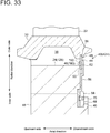
FIG. 33 is a diagram for describing the configuration of a seal plate assembly 42(42H) according to an embodiment, which shows a partial cross-section of agas turbine rotor 16 taken along the axial direction. -
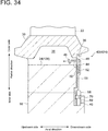
FIG. 34 is a diagram for describing the configuration of a seal plate assembly 42(42H) according to an embodiment, which shows a partial cross-section of agas turbine rotor 16 taken along the axial direction. -
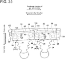
FIG. 35 is a diagram for describing the configuration of a seal plate assembly 42(42H) according to an embodiment, which shows a partial cross-section of agas turbine rotor 16 taken along the axial direction. -
FIG. 36 is a diagram for describing the configuration of a seal plate assembly 42(42I) according to an embodiment, which shows a partial cross-section of agas turbine rotor 16 taken along the axial direction. -
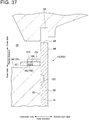
FIG. 37 is a diagram for describing the configuration of a seal plate assembly 42(42I) according to an embodiment, which shows a partial cross-section of agas turbine rotor 16 taken along the axial direction. -
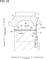
FIG. 38 is a diagram for describing the configuration of a seal plate assembly 42(42J) according to an embodiment, which shows a partial cross-section of agas turbine rotor 16 taken along the axial direction. -
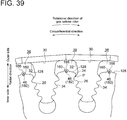
FIG. 39 is a schematic diagram showing the arrangement of sealplate restraint parts 46 of seal plate assemblies 42(42J), viewed from downstream in the axial direction. -
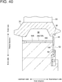
FIG. 40 is a diagram showing a state where a sealplate restraint part 46 is removed in a seal plate assembly 42(42J) according to an embodiment. -
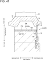
FIG. 41 is a diagram for describing the configuration of a seal plate assembly 42(42K) according to an embodiment, which shows a partial cross-section of agas turbine rotor 16 taken along the axial direction. -
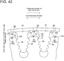
FIG. 42 is a schematic diagram showing the arrangement of sealplate restraint parts 46 of seal plate assemblies 42(42K), viewed from downstream in the axial direction. -
FIG. 43 is a diagram for describing the configuration of a seal plate assembly 42(42L) according to an embodiment, which shows a partial cross-section of agas turbine rotor 16 taken along the axial direction. -
FIG. 44 is a schematic diagram showing a sealplate restraint part 46 of a seal plate assembly 42(42L), viewed from downstream in the axial direction. -
FIG. 45 is a schematic diagram showing a sealplate restraint parts 46 of a seal plate assembly 42(42L), viewed from downstream in the axial direction. -
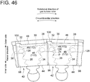
FIG. 46 is a schematic diagram showing a plurality of seal plate assemblies 42(42L), viewed from downstream in the axial direction. -
FIG. 47 is a plan view showing a configuration example of an inspection device for identifying the assembly state of aseal plate assembly 42. -
FIG. 48 is a diagram of an inspection device viewed from upstream in the insertion direction of an inspection rod. -
FIG. 49 is a diagram showing a usage state of the inspection device shown inFIGs. 47 and48 . - Embodiments of the present invention will now be described in detail with reference to the accompanying drawings. It is intended, however, that unless particularly identified, dimensions, materials, shapes, relative positions and the like of components described in the embodiments shall be interpreted as illustrative only and not intended to limit the scope of the present invention.
- For instance, an expression of relative or absolute arrangement such as "in a direction", "along a direction", "parallel", "orthogonal", "centered", "concentric" and "coaxial" shall not be construed as indicating only the arrangement in a strict literal sense, but also includes a state where the arrangement is relatively displaced by a tolerance, or by an angle or a distance whereby it is possible to achieve the same function.
- For instance, an expression of an equal state such as "same" "equal" and "uniform" shall not be construed as indicating only the state in which the feature is strictly equal, but also includes a state in which there is a tolerance or a difference that can still achieve the same function.
- Further, for instance, an expression of a shape such as a rectangular shape or a cylindrical shape shall not be construed as only the geometrically strict shape, but also includes a shape with unevenness or chamfered corners within the range in which the same effect can be achieved.
- On the other hand, an expression such as "comprise", "include", "have", "contain" and "constitute" are not intended to be exclusive of other components.
-
FIG. 1 is a schematic cross-sectional view of agas turbine 2 according to an embodiment of the present invention, taken along the rotational axis of thegas turbine 2. - As shown in
FIG. 1 , thegas turbine 2 includes acompressor 4 for compressing air to produce compressed air, a combustor 6 for mixing the compressed air with fuel supplied from a fuel supply source (not shown) and combusting the mixture to produce combustion gas, and aturbine 8 rotationally driven by the combustion gas. - The
turbine 8 includes aturbine casing 10, a plurality ofvane rows 12 fixed to an inner side of theturbine casing 10, and agas turbine rotor 16 including a plurality ofblade rows 14 and configured to rotate within theturbine casing 10. Thegas turbine rotor 16 includes a plurality ofrotor discs 18 arranged in the axial direction of the rotor and mutually connected. Each of therotor discs 18 is mounted with a corresponding one of theblade rows 14. Thevane rows 12 and theblade rows 14 are arranged alternately along the axial direction of thegas turbine rotor 16. - Each of the
vane rows 12 includes a plurality ofvanes 20 arranged in the circumferential direction of thegas turbine rotor 16, and each of thevanes 20 is fixed to the inner side of theturbine casing 10. Each of theblade rows 14 includes a plurality ofblades 22 arranged in the circumferential direction of thegas turbine rotor 16, and each of theblades 22 is mounted to an outer peripheral surface of therotor disc 18. - Hereinafter, unless otherwise stated, the axial direction of the gas turbine rotor 16 (axial direction of the rotor disc 18) is referred to as merely "axial direction" or "axially", and the circumferential direction of the gas turbine rotor 16 (circumferential direction of the rotor disc 18) is referred to as merely "circumferential direction" or "circumferentially", and the radial direction of the gas turbine rotor 16 (radial direction of the rotor disc 18) is referred to as merely "radial direction" or "radially". Further, the upstream side and the downstream side of a combustion gas flow in the axial direction are referred to as merely "upstream side in axial direction" or "axially upstream side" and "downstream side in axial direction" or "axially downstream side", respectively.
-
FIG. 2 is a schematic configuration diagram of theblade 22.FIG. 3 is a schematic configuration diagram of ablade groove 26 formed in the outerperipheral surface 24 of thegas turbine rotor 16. - As shown in
FIG. 2 , theblade 22 includes ablade body 28, aplatform 30 disposed on an inner side of theblade body 28 in the radial direction, ashank 32 disposed on an inner side of theplatform 30 in the radial direction, and ablade root 34 disposed on an inner side of theshank 32 in the radial direction. An inner peripheral surface of an axially downstream end portion of theplatform 30 has anouter groove 36 recessed outward in the radial direction and extending in the circumferential direction. The cross-section of the blade root 34 (cross-section perpendicular to the chordwise direction of the blade body 28) has a Christmas-tree-like shape having alternate enlarged and reduced width portions in which the width in the circumferential direction increases and decreases alternately toward the inner side in the radial direction. Further, aclearance 38 is provided between theshanks 32 of twoadjacent blades 22 so that cooling air flows into theclearance 38 to cool theblades 22. - As shown in
FIG. 3 , the outerperipheral surface 24 of therotor disc 18 has ablade groove 26 into which theblade root 34 of theblade 22 is fitted. Theblade groove 26 extends through therotor disc 18 from the upstream end to the downstream end of therotor disc 18 in the axial direction and has a cross-sectional shape corresponding to the Christmas-tree-like shape of theblade root 34. With the above configuration, by inserting theblade root 34 of theblade 22 into theblade groove 26 along the axial direction and fitting theblade root 34 into theblade groove 26, theblade 22 is restrained in the circumferential direction and in the radial direction. Further, therotor disc 18 has aninner groove 40 formed downstream of theblade groove 26, recessed inward in the radial direction, and extending in the circumferential direction. Herein, "outerperipheral surface 24 ofrotor disc 18" means a surface of therotor disc 18 in which theblade groove 26 is formed, and does not include a surface in which theinner groove 40 is formed. -
FIG. 4 is a diagram for describing the configuration of a seal plate assembly 42(42A) according to an embodiment, which shows a partial cross-section of thegas turbine rotor 16 taken along the axial direction. - The
gas turbine rotor 16 includes a plurality of seal plate assemblies 42(42A) for a plurality ofblades 22. - In some embodiments, as shown in
FIG. 4 , the seal plate assembly 42(42A) includes aseal plate 44 disposed downstream of therotor disc 18 in the axial direction, and a sealplate restraint part 46 for restricting movement of theseal plate 44 relative to therotor disc 18 in the radial direction. In the illustrated embodiment, the sealplate restraint part 46 is configured as aplug 45. - The
seal plate 44 has a radiallyouter end portion 48 configured to be fitted into theouter groove 36 of theblade 22 and thereby engages with theblade 22 to restrict movement of theblade 22 along the axial direction. Further, theouter groove 36 restricts movement of theseal plate 44 in the radial direction to prevent radially outward movement of theseal plate 44. Theseal plate 44 has afirst surface 50 and asecond surface 52 which face in opposite directions. Thefirst surface 50 faces upstream in the axial direction, while thesecond surface 52 faces downstream in the axial direction. - The seal
plate restraint part 46 is configured to be switchable between a seal plate restraint state (seeFIG. 4 ) where at least a part of the sealplate restraint part 46 protrudes upstream in the axial direction from theseal plate 44 and thereby restricts movement of theseal plate 44 in the radial direction and a seal plate non-restraint state (seeFIG. 5 ) where movement of theseal plate 44 is not restricted in the radial direction. In the illustrated embodiment, the sealplate restraint part 46 is configured as a movable part capable of protruding from thefirst surface 50 at a variable protruding amount. The sealplate restraint part 46 engages with therotor disc 18 in such a manner that the peripheral surface of the sealplate restraint part 46 is caught on the outerperipheral surface 24 of therotor disc 18, thereby restricting radially inward movement of theseal plate 44. The protruding direction (moving direction) of the sealplate restraint part 46 may not be parallel to the axial direction but includes an axial component. For instance, the sealplate restraint part 46 may protrude (move) along the extension direction of theblade groove 26. - Further, in the illustrated embodiment, the
gas turbine rotor 16 includes a lockingplate 56 for holding theseal plate 44 between the lockingplate 56 and adownstream end surface 54 of therotor disc 18, and alocking piece 58 configured to press the lockingplate 56 to theend surface 54 of therotor disc 18. The lockingplate 56 and thelocking piece 58 are held in theinner groove 40 of therotor disc 18. - The locking
plate 56 includes aplate body part 60 extending in the radial direction along theend surface 54 on the downstream side of thegas turbine rotor 16, a risingpart 62 extending downward from a radially outer end portion of theplate body part 60, and alap part 66 extending radially outward from a downstream end portion of the risingpart 62 and overlapping a radiallyinner end portion 64 of theseal plate 44 in the radial direction. Thus, the lockingplate 56 has a crank-shaped cross-section. Thelap part 66 is disposed with a gap from theend surface 54 on the downstream side of thegas turbine rotor 16, and the radiallyinner end portion 64 of theseal plate 44 is held within the gap. As shown inFIG. 4 , in a state where the sealplate restraint part 46 engages with the outerperipheral surface 24 of therotor disc 18, a distance A between the radiallyinner end portion 64 of theseal plate 44 and the risingpart 62 in the radial direction is larger than a depth B of the outer groove 36 (depth based on adownstream edge 63 in the outer groove 36). Thus, by moving theseal plate 44 radially inward by a distance equal to or more than the dimension B, it is possible to release the restriction of axially upstream movement of theblade 22 by theseal plate 44. - The locking
piece 58 includes asupport plate 68 and apressing screw 70. Thesupport plate 68 is disposed downstream of theplate body part 60 in the axial direction so as to adjoin theplate body part 60 and extends along theplate body part 60 in the radial direction. Thepressing screw 70 is screwed into thesupport plate 68. In response to rotation of thepressing screw 70, thesupport plate 68 is separated from the lockingplate 56 in the axial direction, and thesupport plate 68 and the lockingplate 56 are fixed to theinner groove 40 by tension. -
FIG. 6 is an enlarged cross-sectional view of the vicinity of the sealplate restraint part 46 of the seal plate assembly 42(42A), taken along the axial direction. - As shown in
FIG. 6 , theseal plate 44 includes aplate part 72 extending in the radial direction and an accommodationchamber forming part 76 forming anaccommodation chamber 74 for at least partially accommodating the sealplate restraint part 46. The sealplate restraint part 46 is configured so that a part of the sealplate restraint part 46 is capable of protruding from anopening 78 formed in an axially upstream portion (first surface 50 of seal plate 44) of the accommodationchamber forming part 76. The accommodationchamber forming part 76 is provided in a radially outer portion of theseal plate 44 and protrudes downstream in the axial direction (direction to whichsecond surface 52 faces) from theplate part 72. - The accommodation
chamber forming part 76 of theseal plate 44 includes acylindrical part 82 extending upstream in the axial direction from awall part 80 disposed downstream in the axial direction, and afemale thread 84 extending along the axial direction (direction perpendicular to first surface 50) is formed in an inner peripheral surface of thecylindrical part 82. - An axially downstream end portion of the seal
plate restraint part 46 has amale thread 86 configured to be screwed with thefemale thread 84. The sealplate restraint part 46 includes abrim part 88 adjoining the axially upstream side of themale thread 86 and protruding in the radial direction of themale thread 86, and a protrudingpart 90 protruding upstream in the axial direction from thebrim part 88. - The protruding
part 90 of the sealplate restraint part 46, i.e., the axially upstream end portion of the sealplate restraint part 46 has ajig engagement portion 92 capable of engaging with a jig for rotating the sealplate restraint part 46. Thejig engagement portion 92 is formed as a recess having a non-circular (e.g., hexagonal) cross-sectional shape in a surface of the protrudingpart 90 of the sealplate restraint part 46 which faces in the same direction as thefirst surface 50. - The seal plate assembly 42(42A) includes a biasing
part 94 disposed on the outer peripheral side of thecylindrical part 82 and configured to bias thebrim part 88 upstream in the axial direction. The biasingpart 94 biases the sealplate restraint part 46 in a direction in which the sealplate restraint part 46 protrudes from thefirst surface 50. The biasingpart 94 includes, for instance, a disc spring, a coil spring, or a leaf spring. In case of using the disc spring as the biasingpart 94, even if cracks occur in the biasingpart 94, the axial size of the biasingpart 94 is not likely to become small. Thus, it is possible to bias the sealplate restraint part 46 relatively stably. In the illustrated embodiment, anannular spacer 193 is provided on the outer peripheral side of thecylindrical part 82. Theannular spacer 193 is sandwiched between thewall part 80 and the disc spring serving as the biasingpart 94. - The accommodation
chamber forming part 76 includes abrim restraint part 96 disposed upstream of thebrim part 88 in the axial direction to restrict axially upstream movement of thebrim part 88. Theopening 78 is provided in thebrim restraint part 96, and a part of the protrudingpart 90 is configured to protrude upstream in the axial direction from theopening 78 in a state where thebrim part 88 abuts on thebrim restraint part 96. -
FIG. 7 is a schematic diagram showing the arrangement of a plurality of seal plate assemblies 42(42A), viewed from downstream in the axial direction. - As shown in
FIG. 7 , the seal plate assemblies 42(42A) are arranged in the circumferential direction, and a circumferential end portion of theseal plate 44 of each seal plate assembly 42(42A) is superimposed on a circumferential end portion of another circumferentially adjacent seal plate 44 (orseal plate 110 described later) to form a steppedportion 98 where the circumferential end portions of the twoadjacent seal plates 44 overlap each other. This structure prevents leakage of cooling air in theclearance 38 through a gap between the circumferential end portions of the circumferentiallyadjacent seal plates 44 to a space downstream of therotor disc 18 in the axial direction. - The
clearance 38 is formed between aregion 128 on the outerperipheral surface 24 of therotor disc 18 except theblade groove 26 and theplatform 30 of theblade 22, as shown inFIG. 7 . Further, thejig engagement portion 92 of the sealplate restraint part 46 is disposed to overlap theclearance 38 when viewed in the axial direction. Here, when the radially outermost position of a portion fitted with theblade 22 on the outerperipheral surface 24 of therotor disc 18 is defined as position P, theblade groove 26 means a portion of the outerperipheral surface 24 positioned radially inside the position P. Further, theregion 128 means a portion of the outerperipheral surface 24 positioned radially outside the position P. - Further, the radially outer end portion 48 (upper edge) of the
seal plate 44 is provided with aprojection 100 protruding radially outward. Theprojection 100 is disposed across the center of theseal plate 44 in the circumferential direction from the sealplate restraint part 46. The radiallyouter end portion 48 of theseal plate 44 and theprojection 100 are together fitted into the outer groove 36 (seeFIG. 6 ). At this time, theprojection 100 of theseal plate 44 abuts on a step (not shown) provided in theouter groove 36 and thereby restricts movement of theseal plate 44 in the circumferential direction. In other embodiments, theprojection 100 and the sealplate restraint part 46 may be positioned on the same side of the center of theseal plate 44 in the circumferential direction, or theprojection 100 may be positioned at the center of theseal plate 44 in the circumferential direction. Alternatively, the sealplate restraint part 46 may be positioned at the center of theseal plate 44 in the circumferential direction. -
FIG. 8 is a schematic diagram showing the seal plate assembly 42(42A), viewed from upstream in the axial direction.FIG. 9 is a schematic diagram showing the seal plate assembly, viewed from downstream in the axial direction.FIG. 10 is a schematic cross-sectional view taken along line A-A inFIG. 8 . In the illustrated exemplary embodiment, theseal plate 44 is formed in a rectangular shape when viewed in the axial direction, in which the long-side direction of theseal plate 44 coincides with the circumferential direction, the short-side direction of theseal plate 44 coincides with the radial direction, and the thickness direction of theseal plate 44 coincides with the axial direction. In the illustrated embodiment, the width direction of theseal plate 44 is perpendicular to each of the protruding direction (radial direction) of theprojection 100 of theseal plate 44 and the thickness direction (axial direction) of theseal plate 44. Further, the width direction of theseal plate 44 is perpendicular to each of the extension direction (radial direction) of the steppedportions 98 disposed on both circumferential ends of theseal plate 44 to overlap flankingseal plates 44 and the protruding direction (axial direction) of the sealplate restraint part 46. - As shown in
FIGs. 6 and10 , the accommodationchamber forming part 76 protrudes downstream in the axial direction (direction to whichsecond surface 52 faces) from theplate part 72 in both a range where the sealplate restraint part 46 exists in the circumferential direction (width direction of seal plate 44) (seeFIG. 6 ) and a range where the sealplate restraint part 46 does not exist in the circumferential direction (seeFIG. 10 ). As shown inFIGs. 6 and10 , an axiallydownstream end surface 102 of the accommodationchamber forming part 76 is formed along a plane perpendicular to the axial direction. Further, as shown inFIG. 9 , the accommodationchamber forming part 76 protrudes downstream in the axial direction from theplate part 72 over a range W1 which is 80% or more of an existence range W0 where theseal plate 44 exists in the circumferential direction. In the embodiment shown inFIG. 9 , the accommodationchamber forming part 76 protrudes downstream uniformly over the entire circumferential range W1 except for a range where the steppedportion 98 is formed on one circumferential side of the downstream surface of theseal plate 44. - As shown in
FIG. 10 , theplate part 72 of theseal plate 44 includes two or more portions having different thicknesses. In the illustrated embodiment, the thickness t1 of the radiallyinner end portion 64 of theplate part 72 is larger than the thickness t2 of aportion 105 of theplate part 72 between the radiallyinner end portion 64 and the accommodationchamber forming part 76. - As shown in
FIG. 8 , the accommodationchamber forming part 76 has at least one recessed or thinned portion 104 (first thinned part) at a position different from theaccommodation chamber 74. In the illustrated exemplary embodiment, the at least one thinnedportion 104 includes a plurality of thinnedportions 104 disposed on different positions from theaccommodation chamber 74 in the circumferential direction, and each of the thinnedportions 104 is disposed in a range overlapping theaccommodation chamber 74 in the radial direction. Further, the circumferential size S1 of the thinnedportion 104 is larger than the circumferential size S2 of the protrudingpart 90 of the sealplate restraint part 46, and the radial size S3 of the thinnedportion 104 is larger than the radial size S4 of the protrudingpart 90 of the sealplate restraint part 46. In other embodiments, the magnitude relationship between the sizes S1, S2, S3, S4 may be different from the above relationship. By adjusting the size, shape, number or arrangement of the thinned portion appropriately, it is possible to adjust the stiffness of theblade 22 and adjust the natural frequency. - As shown in
FIG. 8 , ajig engagement recess 108 capable of engaging with a jig is formed in thefirst surface 50 of theseal plate 44. Thejig engagement recess 108 is configured as at least one slot having a circumferential length S5 longer than a radial length S6. In the illustrated exemplary embodiment, onejig engagement recess 108 is provided on each of the circumferential ends of theseal plate 44. As shown inFIG. 7 , eachjig engagement recess 108 is positioned so as to overlap theclearance 38 between a region of the outerperipheral surface 24 of therotor disc 18 except theblade groove 26 and the platform of the blade 22 (clearance between shanks 32), when viewed in the axial direction. Further, a direction of a straight line connecting these jig engagement recesses 108 coincides with the width direction of theseal plate 44. In other embodiments, a jig engagement protrusion capable of engaging with a jig may be formed on thefirst surface 50 of theseal plate 44. - Generally, a blade is inserted into a blade groove extending obliquely with respect to the axial direction of a rotor disc. Accordingly, for instance, in a case where a rod-like jig is inserted into the
clearance 38 between theblades 22 on the radially inner side of theplatforms 30 of theblades 22 shown inFIG. 7 to move theseal plate 44 in the radial direction by the jig, the jig engagement recesses 108 is preferably configured as a slot having a circumferential length S5 longer than a radial length S6, as described above. Thereby, it is possible to easily inert a rod-like jig into the jig engagement recesses 108 while the jig is inclined with respect to the first surface 50 (axially upstream facing surface) of theseal plate 44. Thus, it is easy to move theseal plate 44 in the radial direction. -
FIG. 11 is a schematic diagram of aseal plate 110 according to an embodiment, viewed from upstream in the axial direction.FIG. 12 is a schematic diagram of theseal plate 110 according to an embodiment, viewed from downstream in the axial direction.FIG. 13 is a schematic cross-sectional view taken along line B-B inFIG. 11 .FIG. 14 is a diagram showing the circumferential arrangement of theseal plate assemblies 42 and theseal plates 110 in thegas turbine rotor 16 according to an embodiment. - In an embodiment, as shown in
FIGs. 11 to 14 , thegas turbine rotor 16 includes aseal plate assembly 42 and a plurality ofseal plates 44 each disposed at a position different from theseal plate assembly 42 and not provided with the sealplate restraint part 46. - As shown in
FIGs. 11 to 13 , theseal plate 110 includes aplate part 112 and a projectingpart 114 protruding downstream in the axial direction (direction to whichsecond surface 52 ofseal plate 44 faces) from theplate part 112. The projectingpart 114 includes at least one recessed or thinned portion 116 (second thinned portion) having different dimension from the thinnedportion 104. In the illustrated embodiment, the at least one thinnedportion 116 includes a plurality of thinnedportions 116 arranged in the circumferential direction. The radial size S7 of each thinnedportion 116 is larger than the circumferential size S8 of each thinnedportion 116. Further, the radial dimension h2 of a portion of theseal plate 110 except aprojection 122 described later is larger than the radial dimension h1 of a portion of theseal plate 44 except theprojection 100. - The
seal plates 110 are arranged in the circumferential direction, and a circumferential end portion of eachseal plate 110 is superimposed on a circumferential end portion of another circumferentiallyadjacent seal plate 110 to form a steppedportion 118 where the circumferential end portions of the twoadjacent seal plates 110 overlap each other. This structure prevents leakage of cooling air in theclearance 38 through a gap between the circumferential end portions of the circumferentiallyadjacent seal plates 110 to combustion gas. - Further, a radially
outer end portion 120 of theseal plate 110 is provided with aprojection 122 protruding radially outward. The radiallyouter end portion 120 of theseal plate 110 and theprojection 122 are together fitted into the outer groove 36 (seeFIG. 6 ) of theblade 22. At this time, theprojection 122 of theseal plate 110 abuts on a step (not shown) provided in theouter groove 36 and thereby restricts movement of theseal plate 110 in the circumferential direction. - As shown in
FIG. 13 , an axiallydownstream end surface 118 of the projectingpart 114 is formed along a plane perpendicular to the axial direction. Further, as shown inFIG. 12 , the projectingpart 114 protrudes downstream in the axial direction from theplate part 72 over a range W3 which is 80% or more of an existence range W2 where theseal plate 44 exists in the circumferential direction. In the embodiment shown inFIG. 12 , the projectingpart 114 protrudes downstream uniformly over the entire circumferential range W3 except for a range where the stepped portion is formed on one circumferential side of the downstream surface of theseal plate 110. - As shown in
FIG. 13 , theplate part 112 of theseal plate 110 includes two or more portions having different thicknesses. In the illustrated embodiment, the thickness t3 of the radiallyinner end portion 124 of theplate part 112 is equal to the thickness t1, and the thickness t4 of aportion 126 of theplate part 112 between the radiallyinner end portion 124 and the accommodationchamber forming part 76 is equal to the thickness t2. Further, the protrusion amount H2 of the projectingpart 114 from the plate part in the axial direction is equal to the protrusion amount H1 (seeFIG. 10 ) of the accommodation chamber forming part of the seal plate from the plate part in the axial direction. - As shown in
FIG. 14 , the plurality ofseal plate assemblies 42 includes two or moreseal plate assemblies 42 which are adjacent to each other in the circumferential direction. Further, the plurality ofseal plate assemblies 42 includes a plurality ofseal plate assemblies 42 arranged symmetrically with respect to the rotation center O of therotor disc 18. - In the illustrated exemplary embodiment, the plurality of
seal plate assemblies 42 includes threeseal plate assemblies 42 which are adjacent in the circumferential direction and other threeseal plate assemblies 42 which are symmetrical to the former threeseal plate assemblies 42 with respect to the rotation center O. Further, in an angular range where the sixseal plate assemblies 42 are not disposed in the circumferential direction, a plurality ofseal plates 110 not provided with the sealplate restraint part 46 are arranged in the circumferential direction. Although theseal plate 44 provided with the sealplate restraint part 46 differs from theseal plates 110 not provided with the sealplate restraint part 46 in radial dimension of a portion of the seal plate except the projection, lockingplates 56 for holding theseal plate 44 and theseal plate 110 may have the same shape, and lockingpieces 58 configured to press the respective locking plates toward theend surface 54 of therotor disc 18 may have the same shape. - A method for disassembling/assembling the
gas turbine 2 having the above configuration (method for disassembling or assembling gas turbine) will now be described. Firstly, the method for disassembling thegas turbine 2 will be described. Thegas turbine 2 is disassembled, for instance, at the time of maintenance. - First, as shown by arrow a1 in
FIG. 15 , a jig (not shown) is engaged with thejig engagement portion 92 of the sealplate restraint part 46 through theclearance 38 from the upstream side in the axial direction. Then, the sealplate restraint part 46 is rotated and screwed by the jig to move the sealplate restraint part 46 downstream along the axial direction. That is, the sealplate restraint part 46 is moved relative to theseal plate 44. Thereby, a seal plate restraint state (seeFIG. 15 ) where at least a part of the sealplate restraint part 46 protrudes upstream in the axial direction from theseal plate 44 and thereby restricts movement of theseal plate 44 in the radial direction is switched to a seal plate non-restraint state (seeFIG. 16 ) where the sealplate restraint part 46 does not restrict movement of theseal plate 44 in the radial direction (seal-plate-restraint-state switching step). - In the seal-plate-restraint-state switching step, by moving the seal
plate restraint part 46 downstream in the axial direction, an engagement state (seeFIG. 15 ) where the sealplate restraint part 46 engages with the outerperipheral surface 24 of therotor disc 18 is switched to a non-engagement state (seeFIG. 16 ) where the sealplate restraint part 46 does not engage with the outerperipheral surface 24 of therotor disc 18, thus switching between the seal plate restraint state and the seal plate non-restraint state. That is, in the seal-plate-restraint-state switching step, the sealplate restraint part 46 is moved from a position (seeFIG. 15 ) where the sealplate restraint part 46 and the outerperipheral surface 24 of therotor disc 18 overlap in the axial direction to a position (seeFIG. 16 ) where the sealplate restraint part 46 and the outerperipheral surface 24 of therotor disc 18 do not overlap in the axial direction to switch between the seal plate restraint state and the seal plate non-restraint state. - Next, a jig is engaged with the jig engagement recess 108 (see
FIG. 8 ) of theseal plate 44 from the upstream side in the axial direction. Then, as shown by arrow a2 inFIG. 16 , theseal plate 44 is pushed down and moved radially inward by the jig to release engagement between the radiallyouter end portion 48 of theseal plate 44 and theouter groove 36 of theblade 22. Thereby, a blade restraint state (seeFIG. 16 ) where theseal plate 44 restricts movement of theblade 22 along the axial direction is switched to a blade non-restraint state (seeFIG. 17 ) where theseal plate 44 does not restrict movement of theblade 22 along the axial direction (blade-restraint-state switching step). - Then, as shown by arrow a3 in
FIG. 18 , theblade 22 is pulled out upstream in the axial direction from theblade groove 26 of therotor disc 18 to switch from a blade fitting state (seeFIG. 3 ) where theblade root 34 of theblade 22 is fitted in theblade groove 26 of therotor disc 18 to a blade non-fitting state where theblade root 34 of theblade 22 is not fitted in theblade groove 26 of the rotor disc 18 (blade-fitting-state switching step). By executing the above steps, removal of theblade 22 from therotor disc 18 is completed. - Secondly, the method for assembling the
gas turbine 2 will be described. Thegas turbine 2 is assembled, for instance, at the time of manufacturing thegas turbine 2 or at the time of maintenance. The procedure of the method for assembling thegas turbine 2 is reverse to that of the method for disassembling thegas turbine 2, as described below. - First, as shown by arrow a4 in
FIG. 19 , theblade root 34 of theblade 22 is inserted into the blade groove 26 (seeFIG. 3 ) of therotor disc 18 from the upstream side in the axial direction to switch from the blade non-fitting state where theblade root 34 of theblade 22 is not fitted in theblade groove 26 of therotor disc 18 to the blade fitting state where theblade root 34 of theblade 22 is fitted in theblade groove 26 of the rotor disc 18 (blade-fitting-state switching step). - Next, as shown by arrow a5 in
FIG. 20 , a jig is engaged with the jig engagement recess 108 (seeFIG. 8 ) of theseal plate 44 through theclearance 38 from the upstream side in the axial direction. Then, as shown by arrow a6, theseal plate 44 is pushed up and moved radially outward by the jig to engage the radiallyouter end portion 48 of theseal plate 44 with theouter groove 36 of theblade 22. Thereby, the blade non-restraint state (seeFIG. 20 ) where theseal plate 44 does not restrict movement of theblade 22 along the axial direction is switched to the blade non-restraint state (seeFIG. 21 ) where theseal plate 44 restricts movement of theblade 22 along the axial direction (blade-restraint-state switching step). - Then, a jig (not shown) is engaged with the
jig engagement portion 92 of the sealplate restraint part 46 from the upstream side in the axial direction. Then, the sealplate restraint part 46 is rotated by the jig to move the sealplate restraint part 46 upstream along the axial direction. Thereby, the seal plate non-restraint state (seeFIG. 21 ) where the sealplate restraint part 46 does not restrict movement of theseal plate 44 in the radial direction is switched to the seal plate restraint state (seeFIG. 22 ) where at least a part of the sealplate restraint part 46 protrudes upstream in the axial direction from theseal plate 44 and thereby restricts movement of theseal plate 44 in the radial direction (seal-plate-restraint-state switching step). - In the seal-plate-restraint-state switching step, by moving the seal
plate restraint part 46 upstream in the axial direction, the non-engagement state (seeFIG. 21 ) where the sealplate restraint part 46 does not engage with therotor disc 18 is switched to the engagement state (seeFIG. 22 ) where the sealplate restraint part 46 engages with therotor disc 18, thus switching from the seal plate non-restraint state to the seal plate restraint state. That is, in the seal-plate-restraint-state switching step, the sealplate restraint part 46 is moved from a position (seeFIG. 21 ) where the sealplate restraint part 46 and therotor disc 18 do not overlap in the axial direction to a position (seeFIG. 22 ) where the sealplate restraint part 46 and therotor disc 18 overlap in the axial direction to switch from the seal plate non-restraint state to the seal plate restraint state. By executing the above steps, attachment of theblade 22 to therotor disc 18 is completed. - Thirdly, some advantages obtainable from the above method for disassembling/assembling the
gas turbine 2 will be described. - As described with reference to
FIGs. 15, 16 ,21, and 22 , in the seal-plate-restraint-state switching step, the seal plate non-restraint state and the seal plate restraint state are switched by operating the sealplate restraint part 46 from the upstream side in the axial direction, i.e., from a side on which the sealplate restraint part 46 protrudes from the seal plate 44 (side closer to therotor disc 18 than theseal plate 44 is in axial direction). - Thus, it is possible to switch between the seal plate restraint state and the seal plate non-restraint state from the opposite side of the
rotor disc 18 from theseal plate 44, while visually recognizing whether the sealplate restraint part 46 is in the seal plate restraint state or the seal plate non-restraint state, when disassembling or assembling thegas turbine 2. Thus, it is easy to appropriately switch between the seal plate restraint state and the seal plate non-restraint state from the opposite side of therotor disc 18 from theseal plate 44. - Thus, it is easy to appropriately switch between the engagement state and the non-engagement state between the
seal plate 44 and theblade 22 from the opposite side of therotor disc 18 from theseal plate 44, when disassembling or assembling thegas turbine 2. - In particular, in a case where a casing of the
gas turbine 2 has an opening (e.g., opening for attaching combustor 6 or entrance for operators) on the upstream side of therotor disc 18, it is possible to attach or remove theblade 22 with respect to therotor disc 18, without removing thecasing 10 of thegas turbine 2, from the upstream side of therotor disc 18. Thus, it is possible to improve maintenance performance of thegas turbine 2. - Further, in the seal-plate-restraint-state switching step in the method for disassembling/assembling the
gas turbine 2, the seal plate restraint state and the seal plate non-restraint state are switched by moving the sealplate restraint part 46 along the axial direction. - Thus, for instance, even if force acts on the seal
plate restraint part 46 in a direction different from the axial direction of the sealplate restraint part 46 by friction a7 (seeFIG. 7 ) caused between the outerperipheral surface 24 of therotor disc 18 and the sealplate restraint part 46 due to vibration during turning (low-speed rotation) of thegas turbine rotor 16, or due to acceleration or deceleration of rotation of therotor disc 18 during turning of thegas turbine rotor 16, the seal plate non-restraint state and the seal plate restraint state are not easily switched. - Thus, it is possible to control switching between the engagement state and the non-engagement state between the
seal plate 44 and theblade 22 at an unintended timing. - Further, in the seal-plate-restraint-state switching step in the method for disassembling/assembling the
gas turbine 2, the seal plate restraint state and the seal plate non-restraint state are switched by rotating the sealplate restraint part 46 while the male thread 86 (seeFIG. 6 ) provided in the sealplate restraint part 46 is screwed with the female thread 84 (seeFIG. 6 ) provided in theseal plate 44. - With the above configuration, since the seal plate non-restraint state and the seal plate restraint state are switched by rotating the seal
plate restraint part 46 while themale thread 86 is screwed with thefemale thread 84, it is possible to easily control the protruding state of the sealplate restraint part 46. That is, it is possible to control the moving amount of themale thread 86 relative to thefemale thread 84, and thus it is possible to prevent the sealplate restraint part 46 from protruding unintentionally. Thus, it is possible to enhance the effect of controlling switching between the engagement state and the non-engagement state between theseal plate 44 and theblade 22 at an unintended timing. Further, since the seal plate non-restraint state and the seal plate restraint state are not switched unless the sealplate restraint part 46 is rotated, it is possible to move theseal plate 44 in the radial direction smoothly and easily while keeping the seal plate non-restraint state, for instance. - When the
gas turbine rotor 16 is rotating at high rotational speed, theseal plate 44 is held to theouter groove 36 by centrifugal force, and thus the sealplate restraint part 46 is not in contact with the outerperipheral surface 24 of the rotor disc. However, when thegas turbine rotor 16 is turning, theseal plate 44 moves radially inward due to its own weight, and the sealplate restraint part 46 comes into contact with the outerperipheral surface 24. At this time, the sealplate restraint part 46 intends to rotate in a direction opposite to the rotational direction of thegas turbine rotor 16 due to friction. - Accordingly, the
male thread 86 and thefemale thread 84 are threaded so as to rotate in a direction in which the sealplate restraint part 46 protrudes when they receive friction from the outerperipheral surface 24 of therotor disc 18 during turning of thegas turbine rotor 16. For instance, in a case where the rotational direction of thegas turbine rotor 16 is counterclockwise in the upstream view, themale thread 86 and thefemale thread 84 are threaded so as to rotate in a direction in which the sealplate restraint part 46 protrudes upstream in the axial direction when the sealplate restraint part 46 intends to rotate clockwise in the upstream view. - Further, in the seal-plate-restraint-state switching step in the method for disassembling the
gas turbine 2, the seal plate restraint state and the seal plate non-restraint state are switched by moving the sealplate restraint part 46 along the axial direction against a biasing force of the biasing part 94 (seeFIG. 6 ) biasing the sealplate restraint part 46. - Accordingly, even if a weaker force than the biasing force of the biasing part acts on the seal
plate restraint part 46, the seal plate restraint state is not switched to the seal plate non-restraint state. Thus, it is possible to enhance the effect of controlling switching between the engagement state and the non-engagement state between theseal plate 44 and theblade 22 at an unintended timing. - Further, the biasing force of the biasing
part 94 reduces loosening of thethread 86. Thus, also for this reason, it is possible to enhance the effect of controlling switching between the engagement state and the non-engagement state between theseal plate 44 and theblade 22 at an unintended timing. - Further, in the seal-plate-restraint-state switching step, as shown in
FIGs. 7 ,15 , and21 , the seal plate restraint state and the seal plate non-restraint state are switched by operating the sealplate restraint part 46 from the upstream side in the axial direction, via theclearance 38 between theplatform 30 of theblade 22 and theregion 128 on the outerperipheral surface 24 of therotor disc 18 except theblade groove 26 for receiving theblade 22. In this case, the seal plate restraint state and the seal plate non-restraint state are switched by operating the sealplate restraint part 46 through a space between twoadjacent blades 22 on the radially inner side of the platforms of the twoblades 22. - With this method, it is possible to easily switch between the engagement state and the non-engagement state between the seal plate and the blade. The reasons will now be described.
- The resonance of the
blade 22 can be avoided by adjusting the natural frequency of theblade 22 through adjustment of the length of theshank 32 between theplatform 30 and theblade root 34 of theblade 22. Further, the shape and the size of theblade root 34 of theblade 22 are determined based on required strength. Meanwhile, it is not preferable to increase the outer diameter of therotor disc 18 larger than necessary, in view of suppressing the increase in centrifugal force of therotor disc 18. - Accordingly, in case of adopting a configuration which suppresses the increase in centrifugal force of the
rotor disc 18 while avoiding the resonance of theblade 22, awide clearance 38 is likely to be formed between theplatform 30 of theblade 22 and theregion 128 on the outerperipheral surface 24 of therotor disc 18 except theblade groove 26 for receiving theblade 22. - Thus, it is possible to operate the seal
plate restraint part 46 via thewide clearance 38 to switch between the seal plate non-restraint state and the seal plate restraint state, which facilitates the switching. Consequently, it is possible to easily switch between the engagement state and the non-engagement state between the seal plate and the blade. - Next, modifications according to some embodiments will be described. Seal plate assemblies 42(42B to 42L) according to the following modifications differ from the above-described seal plate assembly 42(42A) in the configuration for switching between the seal plate non-restraint state and the seal plate restraint state. In the following modifications, elements having the same functions as those in the above embodiments are denoted by the same reference signs, and description thereof will be omitted. The characteristic features of each modification will be mainly described below.
-
FIG. 23 is an enlarged cross-sectional view of the vicinity of a seal plate restraint part 46 (movable part) of a seal plate assembly 42(42B) according to an embodiment, taken along the axial direction. - In the seal plate assembly 42(42A) shown in
FIG. 6 , thecylindrical part 82 having thefemale thread 84 is included in the accommodationchamber forming part 76 of theseal plate 44, while themale thread 86 screwed with thefemale thread 84 is included in the sealplate restraint part 46. By contrast, in the seal plate assembly 42(42B) shown inFIG. 23 , thecylindrical part 82 having thefemale thread 84 is included in the sealplate restraint part 46, while themale thread 86 screwed with thefemale thread 84 is included in the accommodationchamber forming part 76 of theseal plate 44. - The above configuration also enables operation on the upstream side in the axial direction to rotate the seal
plate restraint part 46 and thereby move the sealplate restraint part 46 along the axial direction, as in the seal-plate-restraint-state switching step described above. Thereby, it is possible to switch between the seal plate non-restraint state where the sealplate restraint part 46 does not restrict movement of theseal plate 44 in the radial direction and the seal plate restraint state where at least a part of the sealplate restraint part 46 protrudes upstream in the axial direction from theseal plate 44 and thereby restricts movement of theseal plate 44 in the radial direction. -
FIG. 24 is an enlarged cross-sectional view of the vicinity of a seal plate restraint part 46 (movable part) of a seal plate assembly 42(42C) according to an embodiment, taken along the axial direction. - In the
seal plate assembly 42 shown inFIG. 24 , as in the embodiment shown inFIG. 23 , thecylindrical part 82 having thefemale thread 84 is included in the sealplate restraint part 46, while themale thread 86 screwed with thefemale thread 84 is included in the accommodationchamber forming part 76 of theseal plate 44. The outer peripheral surface of thecylindrical part 82 is provided with abrim part 88 protruding outward in the radial direction of thefemale thread 84, and a Nord-Lock washer 130 is disposed between thebrim part 88 and abrim restraint part 96 of the accommodationchamber forming part 76. - The above configuration also enables operation on the upstream side in the axial direction to rotate the seal
plate restraint part 46 and thereby move the sealplate restraint part 46 along the axial direction, as in the seal-plate-restraint-state switching step described above. Thereby, it is possible to switch between the seal plate non-restraint state where the sealplate restraint part 46 does not restrict movement of theseal plate 44 in the radial direction and the seal plate restraint state where at least a part of the sealplate restraint part 46 protrudes upstream in the axial direction from theseal plate 44 and thereby restricts movement of theseal plate 44 in the radial direction. - Further, with the above configuration, since the Nord-
Lock washer 130 serves to restrict rotation of the sealplate restraint part 46, it is possible to control switching between the seal plate restraint state and the seal plate non-restraint state at an unintended timing. -
FIG. 25 is an enlarged cross-sectional view of the vicinity of a seal plate restraint part 46 (movable part) of a seal plate assembly 42(42D) according to an embodiment, taken along the axial direction. - In the embodiment shown in
FIG. 25 , theseal plate assembly 42 includes a sealplate restraint part 46 formed as acylindrical member 85 having a closed axially upstream end, and a biasingpart 94 biasing the sealplate restraint part 46 upstream in the axial direction. In the illustrated embodiment, the biasingpart 94 is configured as a coil spring. The biasingpart 94 is supported by astrut 132 protruding in the axial direction from thewall part 80 on the downstream side of the accommodationchamber forming part 76 of theseal plate 44. The seal plate assembly 42(42D) has a simpler structure than the seal plate assembly 42(42A to 42C) in that a thread mechanism is not provided in the sealplate restraint part 46 and in theseal plate 44. - In the seal plate assembly 42(42D), as shown in
FIGs. 25 and26 , by pushing an axiallyupstream end surface 134 of the sealplate restraint part 46 downstream in the axial direction against the biasing force of the biasingpart 94, the sealplate restraint part 46 can be moved downstream along the axial direction. Thereby, it is possible to switch from the seal plate restraint state (seeFIG. 25 ) where at least a part of the sealplate restraint part 46 protrudes in the axial direction from theseal plate 44 and thereby restricts movement of theseal plate 44 in the radial direction to the seal plate non-restraint state (seeFIG. 26 ) where the sealplate restraint part 46 does not restrict movement of theseal plate 44 in the radial direction. - In the embodiment shown in
FIGs. 25 and26 , in contract to the above-described seal plate assemblies 42(42A to 42C), a thread mechanism is not provided in the seal plate restraint part. Therefore, it is necessary to impart a downstream force to the sealplate restraint part 46 in order to keep the seal plate non-restraint state. Accordingly, in the blade-restraint-state switching step, while pushing theupstream end surface 134 of the sealplate restraint part 46 in the downstream direction to keep the seal plate non-restraint state, a jig is engaged with the jig engagement recess 108 (seeFIG. 8 ) formed in theseal plate 44, and theseal plate 44 is moved in the radial direction. Thereby, the blade restraint state can be switched to the blade non-restraint state. -
FIG. 27 is an enlarged cross-sectional view of the vicinity of a seal plate restraint part 46 (movable part) of a seal plate assembly 42(42E) according to an embodiment, taken along the axial direction. - 42(42E) shown in
FIG. 27 includes a sealplate restraint part 46 configured as apin 93 and a biasingpart 94 configured as a coil spring. The sealplate restraint part 46 includes acompression restriction part 136 disposed on a downstream end in the axial direction, abrim part 88 protruding radially outward from thecompression restriction part 136, and a protrudingpart 90 protruding upstream in the axial direction from thebrim part 88. The biasingpart 94 is configured to bias thebrim part 88 upstream. The accommodationchamber forming part 76 has a facingpart 138 which faces thecompression restriction part 136 in the axial direction. Thecompression restriction part 136 is configured to come into contact with the facingpart 138, and this contact restricts axially downstream movement of the sealplate restraint part 46, thereby preventing excessive compression of the biasingpart 94. The seal plate assembly 42(42E) has a simpler structure than the seal plate assembly 42(42A to 42C) in that a thread mechanism is not provided in the sealplate restraint part 46 and in theseal plate 44. - In the seal plate assembly 42(42E), as shown in
FIGs. 27 and28 , by pushing an axiallyupstream end surface 194 of the sealplate restraint part 46 downstream in the axial direction, the sealplate restraint part 46 can be moved downstream along the axial direction, as in the seal plate assembly 42(42E). Thereby, it is possible to switch from the seal plate restraint state (seeFIG. 27 ) where at least a part of the sealplate restraint part 46 protrudes upstream in the axial direction from theseal plate 44 and thereby restricts movement of theseal plate 44 in the radial direction to the seal plate non-restraint state (seeFIG. 28 ) where the sealplate restraint part 46 does not restrict movement of theseal plate 44 in the radial direction. Further, the blade-restraint-state switching step can also be performed in the same way as in the seal plate assembly 42(42E). -
FIG. 29 is an enlarged cross-sectional view of the vicinity of a seal plate restraint part 46 (movable part) of a seal plate assembly 42(42F) according to an embodiment, taken along the axial direction. - In the embodiment shown in
FIG. 29 , theseal plate 44 and the sealplate restraint part 46 are formed integrally. The sealplate restraint part 46 is formed as abranch part 97 diverging from abody part 95 of theseal plate 44, and protrudes upstream in the axial direction and inward in the radial direction from thebody part 95 in the seal plate restraint state. Thisseal plate assembly 42 has a simpler structure than the seal plate assemblies 42(42A to 42E) in that it does not include the biasing part and the thread mechanism. - In this
seal plate assembly 42, as shown inFIGs. 29 and30 , by pushing an end surface 196 of the sealplate restraint part 46 from the upstream side in the axial direction to plastically deform the sealplate restraint part 46 downstream in the axial direction, it is possible to switch from the seal plate restraint state (seeFIG. 29 ) where at least a part of the sealplate restraint part 46 protrudes upstream in the axial direction from theseal plate 44 and thereby restricts movement of theseal plate 44 in the radial direction to the seal plate non-restraint state (seeFIG. 30 ) where the sealplate restraint part 46 does not restrict movement of theseal plate 44 in the radial direction. Further, by pulling the sealplate restraint part 46 from the upstream side in the axial direction to plastically deform the sealplate restraint part 46 upstream in the axial direction, it is possible to switch from the seal plate non-restraint state (seeFIG. 30 ) where the sealplate restraint part 46 does not restrict movement of theseal plate 44 in the radial direction to the seal plate restraint state (FIG. 29 ) where at least a part of the sealplate restraint part 46 protrudes upstream in the axial direction from theseal plate 44 and thereby restricts movement of theseal plate 44 in the radial direction. -
FIG. 31 is an enlarged cross-sectional view of the vicinity of a seal plate restraint part 46 (movable part) of a seal plate assembly 42(42G) according to an embodiment, taken along the axial direction. - In the embodiment shown in
FIG. 31 , theseal plate 44 includes afemale thread 142 provided in a throughhole 140 which penetrates theseal plate 44 in the axial direction, and the sealplate restraint part 46 is configured as a male thread (screw) 144 screwed with thefemale thread 142. Themale thread 144 has an axial length longer than that of thefemale thread 142. The leading end (axially upstream end) of themale thread 144 is provided with ajig engagement portion 92 capable of engaging with a jig for rotating the male thread. Further, the seal plate assembly 42(42G) includes awasher 146 disposed between the head of themale thread 144 and theseal plate 44. - With the above configuration, by screwing the
male thread 144 into thefemale thread 142 from the downstream side in the axial direction, themale thread 144 penetrates theseal plate 44 and the leading end of themale thread 144 protrudes upstream in the axial direction from theseal plate 44. Theseal plate 44 has a receivingpart 148 for preventing themale thread 144 from falling from theseal plate 44 on the downstream side in the axial direction. The receivingpart 148 has an L-shaped cross-section composed of a protruding portion protruding downstream in the axial direction from a position of theseal plate 44 more radially inward than the throughhole 140 and an extending portion extending radially outward from the downstream end of the protruding portion. Thisseal plate assembly 42 has a simpler structure than some seal plate assemblies 42(42A, 42B, 42D, 42E) described above in that it does not include the biasing part. - In this
seal plate assembly 42, by operating thejig engagement portion 92 of themale thread 144 from the upstream side in the axial direction to rotate themale thread 144, themale thread 144 can be moved along the axial direction. Thereby, it is possible to switch between the seal plate non-restraint state (seeFIG. 32 ) where themale thread 144 does not restrict movement of theseal plate 44 in the radial direction and the seal plate restraint state (seeFIG. 31 ) where at least a part of themale thread 144 protrudes in the axial direction from theseal plate 44 and thereby restricts movement of theseal plate 44 in the radial direction. - The above-described seal plate assemblies 42(42A to 42G) according to some embodiments switch between a state where the seal
plate restraint part 46 does not engage with therotor disc 18 and a state where the sealplate restraint part 46 engages with therotor disc 18 by moving the sealplate restraint part 46 along the axial direction, thereby enabling switching between the seal plate restraint state and the seal plate non-restraint state. - In contrast to them, the following
seal plate assemblies 42 according to some embodiments switch between a state where the sealplate restraint part 46 does not engage with theseal plate 44 and a state where the sealplate restraint part 46 engages with theseal plate 44 by moving the sealplate restraint part 46 along the axial direction, thereby enabling switching between the seal plate restraint state and the seal plate non-restraint state. -
FIG. 33 is a diagram for describing the configuration of a seal plate assembly 42(42H) according to an embodiment, which shows a partial cross-section of thegas turbine rotor 16 taken along the axial direction. - The seal plate assembly shown in
FIG. 33 includes aseal plate 44 and a sealplate restraint part 46 configured as a seal plate fall prevention piece 180 (recess engagement member). Theseal plate 44 has afirst surface 50 and asecond surface 52 which face in opposite directions, as in the above embodiments. Thefirst surface 50 faces upstream in the axial direction, while thesecond surface 52 faces downstream in the axial direction. - In the embodiment shown in
FIG. 33 , arecess 150 is formed in thefirst surface 50. The sealplate restraint part 46 is mounted in therecess 150 of theseal plate 44. The size of the sealplate restraint part 46 in the axial direction is larger than the depth of therecess 150 in the axial direction. Thus, in a state where the sealplate restraint part 46 is mounted in therecess 150, at least a part of the sealplate restraint part 46 protrudes in the axial direction from theseal plate 44 and thereby enables restriction of movement of theseal plate 44 in the radial direction. - With the above configuration, by removing the seal
plate restraint part 46 mounted in therecess 150 of theseal plate 44 from therecess 150, or by mounting the sealplate restraint part 46 in therecess 150, it is possible to switch between the seal plate non-restraint state (seeFIG. 34 ) and the seal plate restraint state (seeFIG. 33 ). That is, a state where the sealplate restraint part 46 does not engage with theseal plate 44 and a state where the sealplate restraint part 46 engages with theseal plate 44 are switched by moving the sealplate restraint part 46 along the axial direction, thereby switching between the seal plate restraint state and the seal plate non-restraint state. Further, the seal plate assembly 42(42H) makes it possible to shorten the length of theseal plate 44 in the radial direction, compared to other embodiments, for instance, the seal plate assembly 42(42A). Further, the length of the lockingplate 56 in the radial direction may be changed as appropriate. - In addition, as shown in
FIG. 35 , two or more sealplate restraint parts 46 may be mounted on theseal plate 44. In the embodiment shown inFIG. 35 , each sealplate restraint part 46 is disposed so as to overlap theclearance 38 when viewed in the axial direction. Further, while, in the illustrated embodiment, therecess 150 is disposed in the vicinity of the center of thefirst surface 50 of theseal plate 44 in the radial direction, it is not limited thereto. Therecess 150 may be disposed in a radially inner end of thefirst surface 50 of theseal plate 44, for instance. -
FIG. 36 is a diagram for describing the configuration of a seal plate assembly 42(42I) according to an embodiment, which shows a partial cross-section of thegas turbine rotor 16 taken along the axial direction. - In the embodiment shown in
FIG. 36 , therotor disc 18 includes a projectingpart 152 protruding radially outward along thefirst surface 50 of theseal plate 44. The projectingpart 152 is provided with a throughhole 154 penetrating in the axial direction, and afemale thread 156 is formed in the throughhole 154. The sealplate restraint part 46 of the seal plate assembly 42(42I) includes amale thread 158 configured to be inserted into the throughhole 154 and screw with thefemale thread 156. An axially downstream end portion of the sealplate restraint part 46 engages with therecess 150 formed in thefirst surface 50 of theseal plate 44. - With the above configuration, by rotating and moving the seal
plate restraint part 46 in the axial direction while themale thread 158 provided in the sealplate restraint part 46 is screwed with thefemale thread 156 provided in therotor disc 18, it is possible to switch between the seal plate non-restraint state (seeFIG. 37 ) where the sealplate restraint part 46 does not restrict movement of theseal plate 44 in the radial direction and the seal plate restraint state (FIG. 36 ) where at least a part of the sealplate restraint part 46 protrudes in the axial direction from theseal plate 44 and thereby restricts movement of theseal plate 44 in the radial direction. -
FIG. 38 is a diagram for describing the configuration of a seal plate assembly 42(42J) according to an embodiment, which shows a partial cross-section of thegas turbine rotor 16 taken along the axial direction. - The
seal plate assembly 42 shown inFIG. 38 includes aseal plate 44 and a sealplate restraint part 46 configured as a seal plate fall prevention pin 182 (recess engagement member). Theseal plate 44 has afirst surface 50 and asecond surface 52 which face in opposite directions, as in the above embodiments. Thefirst surface 50 faces upstream in the axial direction, while thesecond surface 52 faces downstream in the axial direction. - In the embodiment shown in
FIG. 38 , arecess 150 is formed in thefirst surface 50. Further, therotor disc 18 has a throughhole 160 penetrating in the axial direction (direction perpendicular to first surface 50). The seal platefall prevention pin 182 is inserted into the throughhole 160 and extends in the axial direction, and the leading end of the seal platefall prevention pin 182 engages with therecess 150. The throughhole 160 is provided with a stepped portion. A steppedportion 162 formed in the seal platefall prevention pin 182 abuts on the stepped portion of the throughhole 160, thereby determining the position of the seal platefall prevention pin 182 in the axial direction. In the seal plate restraint state, while the steppedportion 162 of the seal platefall prevention pin 182 abuts on the stepped portion of the throughhole 160, the leading end of the seal platefall prevention pin 182 engages with therecess 150 as described above. Further, a fallprevention pin cap 164 for preventing axially upstream movement of the seal platefall prevention pin 182 is disposed on the axially upstream side of the seal platefall prevention pin 182. - In the embodiment shown in
FIGs. 38 and39 , theregion 128 on the outerperipheral surface 24 of therotor disc 18 includes a thickenedportion 166 extending in the axial direction, and the throughhole 160 is formed in the thickenedportion 166. In the illustrated embodiment, the seal platefall prevention pin 182 has a circular cross-sectional shape. - With the above configuration, by operating the seal plate
fall prevention pin 182 via the throughhole 160 to move the seal platefall prevention pin 182 in the axial direction with the fallprevention pin cap 164 being detached, it is possible to switch between a state where the leading end of the seal platefall prevention pin 182 does not engage with therecess 150 of theseal plate 44 and a state where the leading end of the seal platefall prevention pin 182 engages with therecess 150 of theseal plate 44. Thereby, it is possible to switch between the seal plate non-restraint state (seeFIG. 40 ) and the seal plate restraint state (seeFIG. 38 ). - As shown in
FIGs. 41 and42 , the seal platefall prevention pin 182 may be inserted into apin groove part 168 formed in theregion 128 on the outerperipheral surface 24 of therotor disc 18 along the axial direction. In the embodiment shown inFIGs. 41 and42 , thepin groove part 168 has a retainingportion 170 configured to prevent the seal platefall prevention pin 182 from falling out from thepin groove part 168 radially outward. In the illustrated embodiment, the seal platefall prevention pin 182 has a rectangular cross-sectional shape. - With the above configuration, similarly, by moving the seal plate
fall prevention pin 182 in the axial direction, it is possible to switch between a state where the leading end of the seal platefall prevention pin 182 does not engage with therecess 150 of theseal plate 44 and a state where the leading end of the seal platefall prevention pin 182 engages with therecess 150 of theseal plate 44. Thereby, it is possible to switch between the seal plate non-restraint state (seeFIG. 42 ) and the seal plate restraint state (seeFIG. 41 ). -
FIG. 43 is a diagram for describing the configuration of a seal plate assembly 42(42L) according to an embodiment, which shows a partial cross-section of thegas turbine rotor 16 taken along the axial direction. - The
seal plate assembly 42 shown inFIG. 43 includes aneccentric cam 172 as the sealplate restraint part 46. Theeccentric cam 172 includes acam part 174 configured to protrude upstream in the axial direction from theseal plate 44 and ashaft part 176 supporting thecam part 174. An axiallyupstream end surface 198 of theeccentric cam 172 is provided with ajig engagement portion 92 capable of engaging with a jig for rotating theeccentric cam 172. - The
seal plate 44 has a throughhole 178 penetrating in the axial direction, and afemale thread 184 is formed in the throughhole 178. Theeccentric cam 172 is rotatably supported to theseal plate 44 with amale thread 186 formed in theshaft part 176 being screwed with thefemale thread 184 of theseal plate 44. - The peripheral surface of the
cam part 174 includes aflat portion 188 and acurved portion 190, as shown inFIGs. 44 and 45 . A distance between the rotation center C of theeccentric cam 172 and theflat portion 188 is longer than a distance between the rotation center C and thecurved portion 190. With the above configuration, by operating theeccentric cam 172 from the upstream side in the axial direction to rotate around the rotation center C, theseal plate 44 is moved in the radial direction in accordance with the phase of theeccentric cam 172. Thereby, it is possible to switch between the engagement state and the non-engagement state between theseal plate 44 and theblade 22. - A state where the
flat portion 188 of thecam part 174 engages with the outerperipheral surface 24 of therotor disc 18 as shown inFIG. 44 is a state where rotation of theeccentric cam 172 is restricted, i.e., the seal plate restraint state where theeccentric cam 172 restricts movement of theseal plate 44 in the radial direction. Conversely, a state where thecurved portion 190 of thecam part 174 engages with the outerperipheral surface 24 of therotor disc 18 as shown inFIG. 45 is a state where rotation of theeccentric cam 172 is allowed, i.e., the seal plate non-restraint state where theeccentric cam 172 does not restrict movement of the seal plate in the radial direction. - As shown in
FIG. 46 , theeccentric cam 172 is positioned so as to overlap theclearance 38 between the platform of theblade 22 and a region of the outerperipheral surface 24 of therotor disc 18 except theblade groove 26 for receiving theblade 22, when viewed in the axial direction. - With the above configuration, by operating the
eccentric cam 172 from the upstream side in the axial direction to rotate theeccentric cam 172, it is possible to switch between the seal plate non-restraint state where theeccentric cam 172 does not restrict movement of theseal plate 44 in the radial direction and the seal plate restraint state where at least a part of theeccentric cam 172 protrudes upstream in the axial direction from theseal plate 44 and thereby restricts movement of theseal plate 44 in the radial direction. - Although, in the above-described embodiments, the position of the seal
plate restraint part 46 as viewed in the axial direction has been described with the drawings only for the seal plate assemblies 42(42A, 42G, 42L), also in the other seal plate assemblies 42(42B to 42F, 42H, 42I, 42K), the sealplate restraint part 46 is positioned so as to overlap theclearance 38 when viewed in the axial direction. - Thus, it is possible to operate the seal
plate restraint part 46 via thewide clearance 38 to switch between the seal plate non-restraint state and the seal plate restraint state, which facilitates the switching. Consequently, it is possible to easily switch between the engagement state and the non-engagement state between the seal plate and the blade. -
FIG. 47 is a plan view showing a configuration example of an inspection device for identifying the assembly state of the seal plate assembly 42 (which shows a partial cross-section in the vicinity of a holdinghole 522 of an inspection rod holder 520).FIG. 48 is a diagram of an inspection device viewed from upstream in the insertion direction of an inspection rod.FIG. 49 is a diagram showing a usage state of the detection device shown inFIGs. 47 and48 . - The
inspection device 500 shown inFIGs. 47 and48 is used to check appropriateness of the assembly state of theseal plate assembly 42 by measuring whether the protrusion amount of the sealplate restraint part 46 of theseal plate assembly 42 from theseal plate 44 is within a predetermined range, as shown inFIG. 49 . - The
inspection device 500 is useful when it is difficult to directly measure the protrusion amount of the sealplate restraint part 46, and theinspection device 500 can be used for the seal plate assemblies 42(42A to 42I), for instance. Although, in the example shown inFIG. 49 , the inspection target is the seal plate assembly 42(42A to 42H) including the sealplate restraint part 46 engaging with the outerperipheral surface 24 of therotor disc 18, the seal plate assembly 42I can also be inspected by theinspection device 500. - In some embodiments, as shown in
FIGs. 47 and48 , theinspection device 500 includes aninspection rod 510 and aninspection rod holder 520 for holding theinspection rod 510 in a predetermined orientation. - The
inspection rod 510 is movable in a longitudinal direction of theinspection rod 510 relative to theinspection rod holder 520 in a state where theinspection rod 510 is restrained by theinspection rod holder 520 in a predetermined orientation. Theinspection rod 510 is an elongated member longer than theclearance 38 between theshanks 32 of two circumferentiallyadjacent blades 22 and having a cross-sectional shape to pass through theclearance 38. - A
proximal end portion 512 of theinspection rod 510 has at least one measurement surface 514(514A, 514B). The measurement surface 514 is used for determining whether the insertion depth of theinspection rod 510 into theinspection rod holder 520 is within a predetermined range during use of theinspection device 500, as described later in detail. - In the exemplary embodiment shown in
FIG. 47 , a pair ofmeasurement surfaces inspection rod 510. The measurement surfaces 514A, 514B are located at different positions in the longitudinal direction of theinspection rod 510. A distance ΔZ between the measurement surfaces 514A and 514B is set to be smaller than (e.g., 0.5 times or less) the protrusion length of the sealplate restraint part 46 when the seal plate assembly 42(42A to 42H) is in the appropriate assembly state (i.e., length of engagement between sealplate restraint part 46 and outerperipheral surface 24 of rotor disc 18). - A
distal end portion 516 of theinspection rod 510 is a portion which comes into contact with the sealplate restraint part 46 during use of theinspection device 500. Thedistal end portion 516 may be configured to be insertable into a recess (not shown inFIG. 49 ) provided in the sealplate restraint part 46. In this case, thedistal end portion 516 of theinspection rod 510 is easily brought into contact with a predetermined portion in the recess of the sealplate restraint part 46 during use of theinspection device 500, and thus it is possible to improve the reliability of inspection. - The recess of the seal
plate restraint part 46 may be thejig engagement portion 92. - The
inspection rod 510 includes anenlarged diameter part 518, disposed on the distal end side of the measurement surface 514, for engaging with anenlarged diameter portion 522A of the holdinghole 522. During use of theinspection device 500, theenlarged diameter part 518 of theinspection rod 510 is fitted into theenlarged diameter portion 522A of the holdinghole 522, so that the orientation of theinspection rod 510 is restricted. Thus, it is possible to perform stable inspection with theinspection device 500. - On the other hand, the
inspection rod holder 520 has the holdinghole 522 for holding theinspection rod 510, and an axial-direction positioning surface 524 for determining the position of theinspection rod holder 520 with respect to the axial direction of thegas turbine 2 during use of theinspection device 500. - In the exemplary embodiment shown in
FIG. 47 , the axial-direction positioning surface 524 abuts on an axial-direction reference surface 600 (seeFIG. 49 ) during use of theinspection device 500, and thereby enabling positioning of theinspection rod holder 520 with respect to the axial direction. The axial-direction reference surface 600 may be an axial end surface of therotor disc 18 as in the example shown inFIG. 49 , or may be an axial end surface of theshank 32 or theblade root 34 of theblade 22. - Further, the
inspection rod holder 520 may include, in addition to the axial-direction positioning surface 524, a radial-direction positioning surface 526 which abuts on a radial-direction reference surface 610 during use of theinspection device 500 for positioning of theinspection rod holder 520 with respect to the radial direction. In the example shown inFIG. 49 , the radial-direction reference surface 610 is provided on therotor disc 18. - The radial-
direction positioning surface 526 of theinspection rod holder 520 may have a shape corresponding to the radial-direction reference surface 610. In the example shown inFIG. 48 , the radial-direction positioning surface 526 has an arc shape when viewed from upstream in the insertion direction of theinspection rod 510. - The
inspection rod holder 520 has ameasurement reference surface 528 in the vicinity of the opening of the holdinghole 522. Themeasurement reference surface 528 is a surface serving as a reference to be compared with the position of the measurement surface 514(514A, 514B) of theinspection rod 510 during use of theinspection device 500. - In the example shown in
FIG. 47 , themeasurement reference surface 528 is provided, in the vicinity of the holdinghole 522, at an end surface of theinspection rod holder 520 opposite the axial-direction positioning surface 524, as a flat surface perpendicular to the axial direction of the holdinghole 522. The example shown inFIGs. 47 to 49 is designed assuming that theclearance 38 between theshanks 32 of circumferentiallyadjacent blades 22 extends obliquely with respect to the axial direction of thegas turbine 2, and thus themeasurement reference surface 528 and the axial-direction positioning surface 524 are not parallel to each other but titled at an inclination angle. However, it is not limited to this example. - When using the
inspection device 500 with the above configuration, as shown inFIG. 49 , first, the axial-direction positioning surface 524 and the radial-direction positioning surface 526 of theinspection rod holder 520 are brought into contact with the axial-direction reference surface 600 and the radial-direction reference surface 610, respectively, to determine the position of theinspection rod holder 520. Thus, the relative position of themeasurement reference surface 528 of theinspection rod holder 520 with respect to theseal plate assembly 42 is determined. - Next, the
inspection rod 510 is inserted into the holdinghole 522 of theinspection rod holder 520, and theinspection rod 510 is pushed into the holdinghole 522 until thedistal end portion 516 of theinspection rod 510 comes into contact with the sealplate restraint part 46 of theseal plate assembly 42 via theclearance 38. When theinspection rod 510 is pushed, theenlarged diameter part 518 of theinspection rod 510 is fitted into theenlarged diameter portion 522A of the holdinghole 522, so that the orientation of theinspection rod 510 is restricted. Thedistal end portion 516 of theinspection rod 510 may be engaged with the recess (not shown) (e.g., jig engagement portion 92) of the sealplate restraint part 46. - Further, in a state where the
inspection rod 510 is inserted and thedistal end portion 516 of theinspection rod 510 is in contact with the sealplate restraint part 46, it is checked whether the assembly state of theseal plate assembly 42 is appropriate, based on the relative position of the measurement surface 514(514A, 54B) of theinspection rod 510 with respect to themeasurement reference surface 528 of theinspection rod holder 520. - For instance, the position of the
measurement reference surface 528 of theinspection rod holder 520 may be set to be positioned between the pair ofmeasurement surfaces inspection rod 510 in a case where the assembly state of theseal plate assembly 42 is appropriate. Thereby, it is possible to easily check the appropriateness of the assembly state of theseal plate assembly 42. That is, if both the measurement surfaces 514A, 514B are located on a side of themeasurement reference surface 528 on which theseal plate assembly 42 is positioned (i.e., if both the measurement surfaces 514A, 514B are located within the holding hole 522), it is determined that the protrusion amount of the sealplate restraint part 46 from theseal plate 44 is insufficient, and theseal plate assembly 42 is not in the appropriate assembly state. Conversely, if onemeasurement surfaces 514A is located on a side of themeasurement reference surface 528 opposite the side on which theseal plate assembly 42 is positioned (i.e., themeasurement surface 514A is located outside the holding hole 522), and theother measurement surface 514B is located on the side of themeasurement reference surface 528 on which theseal plate assembly 42 is positioned (i.e., themeasurement surface 514B is located within the holding hole 522), it is determined that the protrusion amount of the sealplate restraint part 46 from theseal plate 44 is within a predetermined range, and theseal plate assembly 42 is in the appropriate assembly state. - Although in the
inspection device 500 with the above configuration, the appropriateness of the assembly state of theseal plate assembly 42 is determined based on the relative positional relationship between the measurement surface 514 (514A, 514B) and themeasurement reference surface 528, in other embodiments, the appropriateness of the assembly state of theseal plate assembly 42 may be determined by comparing a mark provided in theinspection rod 510 with themeasurement reference surface 528. - Further, although in the
inspection device 500 with the above configuration, the position of theinspection rod holder 520 is not determined with respect to the circumferential direction of thegas turbine 2, in other embodiments, the device may have a function for positioning theinspection rod holder 520 in the circumferential direction. In this case, at least one of the side surfaces of twoshanks 32 which are adjacent to each other in the circumferential direction via theclearance 38 may be used as a circumferential-direction reference to be brought into contact with a circumferential-direction positioning part of theinspection rod holder 520. - Embodiments of the present invention were described in detail above, but the present invention is not limited thereto, and various amendments and modifications may be implemented.
- For instance, although the seal plate assemblies 42(42A to 42L) have been described in conjunction with the case where the
seal plate assembly 42 is disposed on the downstream side of therotor disc 18 in the axial direction, the seal plate assembly may be disposed on the upstream side of the rotor disc in the axial direction. - That is, the seal plate assembly includes a seal plate disposed on a first side of the rotor disc in the axial direction of the rotor disc, and a seal plate restraint part for restricting movement of the seal plate relative to the rotor disc in the radial direction of the rotor disc. The method for disassembling/assembling a gas turbine includes a seal-plate-restraint-state switching step of operating the seal plate restraint part from a second side in the axial direction to switch between the seal plate non-restraint state where the seal plate restraint part does not restrict movement of the seal plate in the radial direction and the seal plate restraint state where at least a part of the seal plate restraint part protrudes toward the second side in the axial direction from the seal plate and thereby restricts movement of the seal plate in the radial direction.
- Thereby, it is possible to switch between the seal plate restraint state and the seal plate non-restraint state from the opposite side of the rotor disc from the seal plate, while visually recognizing whether the seal plate restraint part is in the seal plate restraint state or the seal plate non-restraint state, when disassembling or assembling the gas turbine. Thus, it is easy to appropriately switch between the seal plate restraint state and the seal plate non-restraint state from the opposite side of the rotor disc from the seal plate. Consequently, it is easy to appropriately switch between the engagement state and the non-engagement state between the seal plate and the blade from the opposite side of the rotor disc from the seal plate, when disassembling or assembling the gas turbine.
-
- 2
- Gas turbine
- 4
- Compressor
- 6
- Combustor
- 8
- Turbine
- 10
- Turbine casing
- 12
- Vane row
- 14
- Blade row
- 16
- Gas turbine rotor
- 18
- Rotor disc
- 20
- Vane
- 22
- Blade
- 24
- Outer peripheral surface
- 26
- Blade groove
- 28
- Blade body
- 30
- Platform
- 32
- Shank
- 34
- Blade root
- 36
- Outer groove
- 38
- Clearance
- 40
- Inner groove
- 42
- Seal plate assembly
- 44, 110
- Seal plate
- 45
- Plug
- 46
- Seal plate restraint part
- 48, 120
- Radially outer end portion
- 50
- First surface
- 52
- Second surface
- 54, 102, 118, 134, 194, 196, 198
- End surface
- 56
- Locking plate
- 58
- Locking piece
- 60
- Plate body part
- 62
- Rising part
- 63
- Edge
- 64, 124
- Radially inner end portion
- 66
- Lap part
- 68
- Plate
- 70
- Pressing screw
- 72, 112
- Plate part
- 74
- Accommodation chamber
- 76
- Accommodation chamber forming part
- 78
- Opening
- 80
- Wall part
- 82
- Cylindrical part
- 84, 142, 156, 184
- Female thread
- 85
- Cylindrical member
- 86
- Thread
- 86
- Male thread
- 86, 144, 158, 186
- Male thread
- 88
- Brim part
- 90
- Protruding part
- 92
- Jig engagement portion
- 94
- Biasing part
- 95
- Body part
- 96
- Brim restraint part
- 97
- Branch part
- 98, 118, 162
- Stepped portion
- 100
- Projection
- 104, 116
- Thinned portion
- 105, 126
- Portion
- 108
- Jig engagement recess
- 114, 152
- Projecting part
- 122
- Projection
- 128
- Region
- 130
- Nord-Lock washer
- 132
- Strut
- 136
- Compression restriction part
- 138
- Facing part
- 140, 154, 160 178
- Through hole
- 146
- Washer
- 148
- Receiving part
- 150
- Recess
- 164
- Fall prevention pin cap
- 166
- Thickened portion
- 168
- Pin groove part
- 170
- Retaining portion
- 172
- Eccentric cam
- 174
- Cam part
- 176
- Shaft part
- 180
- Seal plate fall prevention piece
- 182
- Seal plate fall prevention pin
- 188
- Flat portion
- 190
- Curved portion
- 193
- Annular spacer
- 500
- Inspection device
- 510
- Inspection rod
- 512
- Proximal end portion
- 514 (514A, 514B)
- Measurement surface
- 516
- Distal end portion
- 518
- Enlarged diameter part
- 520
- Inspection rod holder
- 522
- Holding hole
- 522A
- Enlarged diameter portion
- 524
- Axial-direction positioning surface
- 526
- Radial-direction positioning surface
- 528
- Measurement reference surface
- 600
- Axial-direction reference surface
- 610
- Radial-direction reference surface
Claims (40)
- A method for disassembling/assembling a gas turbine,
the gas turbine including a seal plate disposed on a first side of a rotor disc in an axial direction of the rotor disc, and a seal plate restraint part for restricting movement of the seal plate relative to the rotor disc in a radial direction of the rotor disc,
the method comprising a seal-plate-restraint-state switching step of operating the seal plate restraint part from a second side in the axial direction to switch between a seal plate non-restraint state where the seal plate restraint part does not restrict movement of the seal plate in the radial direction and a seal plate restraint state where at least a part of the seal plate restraint part protrudes toward the second side in the axial direction from the seal plate and thereby restricts movement of the seal plate in the radial direction. - The method for disassembling/assembling a gas turbine according to claim 1,
wherein the first side in the axial direction is a downstream side of a combustion gas flow in the axial direction, and the second side in the axial direction is an upstream side of the combustion gas flow in the axial direction. - The method for disassembling/assembling a gas turbine according to claim 1 or 2,
wherein the seal-plate-restraint-state switching step includes operating the seal plate restraint part through a space between two adjacent blades, on a radially inner side of platforms of the two blades, to switch between the seal plate non-restraint state and the seal plate restraint state. - The method for disassembling/assembling a gas turbine according to any one of claims 1 to 3,
wherein the rotor disc includes a through hole extending along the axial direction, and
wherein the seal-plate-restraint-state switching step includes operating the seal plate restraint part via the through hole to switch between the seal plate non-restraint state and the seal plate restraint state. - The method for disassembling/assembling a gas turbine according to any one of claims 1 to 4,
wherein the seal-plate-restraint-state switching step includes switching between a state where the seal plate restraint part does not engage with the rotor disc and a state where the seal plate restraint part engages with the rotor disc by moving the seal plate restraint part along the axial direction to switch between the seal plate non-restraint state and the seal plate restraint state. - The method for disassembling/assembling a gas turbine according to any one of claims 1 to 5,
wherein the seal-plate-restraint-state switching step includes moving the seal plate restraint part between a position where the seal plate restraint part and the rotor disc do not overlap in the axial direction and a position where the seal plate restraint part and the rotor disc overlap in the axial direction to switch between the seal plate non-restraint state and the seal plate restraint state. - The method for disassembling/assembling a gas turbine according to any one of claims 1 to 6,
wherein the seal-plate-restraint-state switching step includes rotating the seal plate restraint part while one of a female thread or a male thread provided in the seal plate restraint part is screwed with the other of the female thread or the male thread provided in the seal plate to switch between the seal plate non-restraint state and the seal plate restraint state. - The method for disassembling/assembling a gas turbine according to any one of claims 1 to 7,
wherein the seal-plate-restraint-state switching step includes moving the seal plate restraint part along the axial direction against a biasing force of a biasing part biasing the seal plate restraint part to switch from the seal plate restraint state to the seal plate non-restraint state. - The method for disassembling/assembling a gas turbine according to any one of claims 1 to 4,
wherein the seal-plate-restraint-state switching step includes switching between a state where the seal plate restraint part does not engage with the seal plate and a state where the seal plate restraint part engages with the seal plate to switch between the seal plate non-restraint state and the seal plate restraint state. - The method for disassembling/assembling a gas turbine according to claim 9,
wherein the seal plate restraint part is a seal plate fall prevention pin extending along the axial direction, and
wherein the seal-plate-restraint-state switching step includes switching between a state where a leading end of the seal plate fall prevention pin does not engage with a recess formed in the seal plate and a state where the leading end of the seal plate fall prevention pin engages with the recess formed in the seal plate to switch between the seal plate non-restraint state and the seal plate restraint state. - The method for disassembling/assembling a gas turbine according to claim 9,
wherein the seal plate restraint part is a seal plate fall prevention piece, and
wherein the seal-plate-restraint-state switching step includes removing the seal plate fall prevention piece mounted in a recess formed in the seal plate from the recess, or mounting the seal plate fall prevention piece in the recess, to switch between the seal plate non-restraint state and the seal plate restraint state. - The method for disassembling/assembling a gas turbine according to claim 9,
wherein the seal-plate-restraint-state switching step includes rotating the seal plate restraint part while a female thread provided in the rotor disc is screwed with a male thread provided in the seal plate restraint part to switch between the seal plate non-restraint state and the seal plate non-restraint state. - The method for disassembling/assembling a gas turbine according to any one of claims 1 to 6,
wherein the seal plate and the seal plate restraint part are formed integrally, and
wherein the seal-plate-restraint-state switching step includes plastically deforming the seal plate restraint part to switch between the seal plate non-restraint state and the seal plate restraint state. - The method for disassembling/assembling a gas turbine according to any one of claims 1 to 6,
wherein the seal-plate-restraint-state switching step includes rotating the seal plate restraint part while a male thread provided in the seal plate restraint part is screwed with a female thread provided in a through hole penetrating the seal plate to switch between the seal plate non-restraint state and the seal plate restraint state. - The method for disassembling/assembling a gas turbine according to any one of claims 1 to 14, further comprising a blade-restraint-state switching step of moving the seal plate in the radial direction to switch between a blade non-restraint state where the seal plate does not restrict movement of a blade along the axial direction and a blade restraint state where the seal plate restraint part restricts movement of the blade along the axial direction.
- The method for disassembling/assembling a gas turbine according to claim 15,
wherein a jig engagement recess or a jig engagement protrusion capable of engaging with a jig is formed in a surface of the seal plate which faces toward the second side in the axial direction, and
wherein the blade-restraint-state switching step includes moving the seal plate in the radial direction while the jig engagement recess or the jig engagement protrusion engages with the jig to switch between the blade non-restraint state and the blade restraint state. - The method for disassembling/assembling a gas turbine according to claim 15 or 16, further comprising a blade-fitting-state switching step of switching a blade non-fitting state where the blade is not fitted in the rotor disc and a blade fitting state where the blade is fitted in the rotor disc.
- A seal plate assembly for a blade of a gas turbine, comprising:a seal plate configured to be disposed on a first side of a rotor disc in an axial direction of the rotor disc; anda seal plate restraint part for restricting movement of the seal plate relative to the rotor disc in a radial direction of the rotor disc,wherein the seal plate restraint part is configured to be switchable between a seal plate restraint state where at least a part of the seal plate restraint part protrudes toward a second side in the axial direction from the seal plate and thereby restricts movement of the seal plate in the radial direction and a seal plate non-restraint state where movement of the seal plate in the radial direction is not restricted.
- The seal plate assembly according to claim 18,
wherein the first side in the axial direction is a downstream side in the axial direction, and the second side in the axial direction is an upstream side in the axial direction. - The seal plate assembly according to claim 18 or 19,
wherein the seal plate includes one of a female thread or a male thread extending along the axial direction, and
wherein the seal plate restraint part includes the other of the female thread or the male thread which is screwed with the one of the female thread or the male thread. - The seal plate assembly according to claim 20, further comprising a washer disposed between the seal plate restraint part and the seal plate.
- The seal plate assembly according to any one of claims 18 to 21,
wherein an end portion of the seal plate restraint part on the second side in the axial direction has a jig engagement portion capable of engaging with a jig for rotating the seal plate restraint part. - The seal plate assembly according to any one of claims 18 to 22, further comprising a biasing part biasing the seal plate restraint part toward the second side in the axial direction.
- The seal plate assembly according to claim 23,
wherein the biasing part includes a disc spring, a coil spring, or a leaf spring. - The seal plate assembly according to any one of claims 18 to 24,
wherein the seal plate includes a plate part extending in the radial direction and an accommodation chamber forming part forming an accommodation chamber for at least partially accommodating the seal plate restraint part, and
wherein the seal plate restraint part is configured so that at least a part of the seal plate restraint part is capable of protruding from an opening formed in the accommodation chamber forming part on the second side in the axial direction. - The seal plate assembly according to claim 25,
wherein the accommodation chamber forming part protrudes toward the first side in the axial direction from the plate part. - The seal plate assembly according to claim 26,
wherein the accommodation chamber forming part protrudes toward the first side in the axial direction from the plate part in both a range where the seal plate restraint part exists in a circumferential direction of the rotor disc and a range where the seal plate restraint part does not exist in the circumferential direction. - The seal plate assembly according to claim 26 or 27,
wherein the accommodation chamber forming part protrudes toward the first side in the axial direction from the plate part over a range of 80% or more of a length of the seal plate in a circumferential direction of the rotor disc. - The seal plate assembly according to any one of claims 25 to 28,
wherein an end surface of the accommodation chamber forming part on the first side in the axial direction is formed along a plane perpendicular to the axial direction. - The seal plate assembly according to any one of claims 25 to 29,
wherein the accommodation chamber forming part is provided in a radially outer portion of the seal plate. - The seal plate assembly according to any one of claims 25 to 30,
wherein the accommodation chamber forming part has a thinned portion at a different position from the accommodation chamber. - The seal plate assembly according to any one of claims 25 to 31,
wherein the plate part includes two or more portions having different thicknesses. - The seal plate assembly according to any one of claims 18 to 32,
wherein one of the seal plate or the seal plate restraint part includes a cylindrical part extending along the axial direction,
wherein a female thread is formed in an inner peripheral surface of the cylindrical part,
wherein the other of the seal plate or the seal plate restraint part includes a male thread screwed with the female thread,
wherein the seal plate restraint part includes a brim part and a protruding part protruding toward the second side in the axial direction from the brim part,
wherein the seal plate assembly further comprises a disc spring disposed on an outer peripheral side of the cylindrical part and configured to bias the brim part toward the second side in the axial direction, and
wherein the seal plate includes a brim restraint part disposed on the second side of the brim part in the axial direction to restrict movement of the brim part toward the second side in the axial direction. - The seal plate assembly according to any one of claims 18 to 33,
wherein a surface of the seal plate which faces toward the second side in the axial direction is provided with at least one slot having a circumferential length in a circumferential direction of the rotor disc and a radial length in the radial direction of the rotor disc, wherein the circumferential length is longer than the radial length. - A gas turbine rotor comprising:a rotor disc;a plurality of blades mounted on the rotor disc; andat least one seal plate assembly for the blades,wherein the at least one seal plate assembly includes the seal plate assembly according to any one of claims 18 to 34.
- The gas turbine rotor according to claim 35, further comprising:a locking plate for holding the seal plate between the locking plate and an end surface of the rotor disc; anda locking piece configured to press the locking plate toward the end surface of the rotor disc.
- A gas turbine rotor comprising:a rotor disc;a plurality of blades mounted on the rotor disc; andat least one seal plate assembly for the blades,wherein the at least one seal plate assembly includes a pair of seal plate assemblies which are adjacent to each other in a circumferential direction of the rotor disc, andwherein each of the pair of seal plate assemblies is the seal plate assembly according to any one of claims 18 to 34.
- A gas turbine rotor comprising:a rotor disc;a plurality of blades mounted on the rotor disc; andat least one seal plate assembly for the blades,wherein the at least one seal plate assembly includes a plurality of seal plate assemblies arranged symmetrically around a rotation center of the rotor disc, andwherein each of the plurality of seal plate assemblies arranged symmetrically is the seal plate assembly according to any one of claims 18 to 34.
- A gas turbine comprising:the gas turbine rotor according to any one of claims 35 to 38; anda casing covering the gas turbine rotor.
- A method for producing a gas turbine,
the gas turbine including a seal plate disposed on a first side of a rotor disc in an axial direction of the rotor disc, and a seal plate restraint part for restricting movement of the seal plate relative to the rotor disc in a radial direction of the rotor disc,
the method comprising a seal-plate-restraint-state switching step of operating the seal plate restraint part from a second side in the axial direction to switch from a seal plate non-restraint state where the seal plate restraint part does not restrict movement of the seal plate in the radial direction to a seal plate restraint state where at least a part of the seal plate restraint part protrudes toward the second side in the axial direction from the seal plate and thereby restricts movement of the seal plate in the radial direction.
Applications Claiming Priority (2)
| Application Number | Priority Date | Filing Date | Title |
|---|---|---|---|
| JP2016241692 | 2016-12-13 | ||
| PCT/JP2017/044653 WO2018110580A1 (en) | 2016-12-13 | 2017-12-13 | Gas turbine disassembling/assembling method, seal plate assembly, and gas turbine rotor |
Publications (3)
| Publication Number | Publication Date |
|---|---|
| EP3536905A1 true EP3536905A1 (en) | 2019-09-11 |
| EP3536905A4 EP3536905A4 (en) | 2020-01-08 |
| EP3536905B1 EP3536905B1 (en) | 2021-04-14 |
Family
ID=62558709
Family Applications (1)
| Application Number | Title | Priority Date | Filing Date |
|---|---|---|---|
| EP17881406.7A Active EP3536905B1 (en) | 2016-12-13 | 2017-12-13 | Gas turbine disassembling/assembling method, seal plate assembly, and gas turbine rotor |
Country Status (9)
| Country | Link |
|---|---|
| US (1) | US11111799B2 (en) |
| EP (1) | EP3536905B1 (en) |
| JP (1) | JP6817329B2 (en) |
| KR (1) | KR102249570B1 (en) |
| CN (1) | CN110062838B (en) |
| MX (1) | MX2019006639A (en) |
| SA (1) | SA519401838B1 (en) |
| TW (1) | TWI705182B (en) |
| WO (1) | WO2018110580A1 (en) |
Families Citing this family (1)
| Publication number | Priority date | Publication date | Assignee | Title |
|---|---|---|---|---|
| US12168940B1 (en) | 2023-09-08 | 2024-12-17 | Pratt & Whitney Canada Corp. | Radial transition fit between primary and secondary parts of a rotor assembly |
Family Cites Families (41)
| Publication number | Priority date | Publication date | Assignee | Title |
|---|---|---|---|---|
| BE551145A (en) * | 1955-09-26 | |||
| US3266770A (en) * | 1961-12-22 | 1966-08-16 | Gen Electric | Turbomachine rotor assembly |
| GB1141280A (en) | 1968-01-17 | 1969-01-29 | Rolls Royce | Bladed rotor for a fluid flow machine |
| US3501249A (en) * | 1968-06-24 | 1970-03-17 | Westinghouse Electric Corp | Side plates for turbine blades |
| US3572966A (en) * | 1969-01-17 | 1971-03-30 | Westinghouse Electric Corp | Seal plates for root cooled turbine rotor blades |
| US3644058A (en) * | 1970-05-18 | 1972-02-22 | Westinghouse Electric Corp | Axial positioner and seal for turbine blades |
| DE2139146A1 (en) | 1971-08-05 | 1973-02-15 | Metallgesellschaft Ag | PROCESS FOR THE RECOVERY OF THE SELECTIVE SOLVENT FROM THE REFINEMENT OF AN EXTRACTIVE DISTILLATION |
| US3728042A (en) * | 1971-08-27 | 1973-04-17 | Westinghouse Electric Corp | Axial positioner and seal for cooled rotor blade |
| US3748060A (en) * | 1971-09-14 | 1973-07-24 | Westinghouse Electric Corp | Sideplate for turbine blade |
| US3853425A (en) * | 1973-09-07 | 1974-12-10 | Westinghouse Electric Corp | Turbine rotor blade cooling and sealing system |
| US4021138A (en) * | 1975-11-03 | 1977-05-03 | Westinghouse Electric Corporation | Rotor disk, blade, and seal plate assembly for cooled turbine rotor blades |
| GB2043796B (en) * | 1979-03-10 | 1983-04-20 | Rolls Royce | Bladed rotor for gas turbine engine |
| US4279572A (en) | 1979-07-09 | 1981-07-21 | United Technologies Corporation | Sideplates for rotor disk and rotor blades |
| JPS6151406A (en) | 1984-08-17 | 1986-03-13 | Agency Of Ind Science & Technol | Belt transfer device |
| JPS6151406U (en) * | 1984-09-07 | 1986-04-07 | ||
| GB2258273B (en) | 1991-08-02 | 1994-08-10 | Ruston Gas Turbines Ltd | Rotor blade locking arrangement |
| US5257909A (en) * | 1992-08-17 | 1993-11-02 | General Electric Company | Dovetail sealing device for axial dovetail rotor blades |
| US6220814B1 (en) * | 1998-07-16 | 2001-04-24 | Siemens Westinghouse Power Corporation | Turbine interstage sealing arrangement |
| US6575703B2 (en) * | 2001-07-20 | 2003-06-10 | General Electric Company | Turbine disk side plate |
| EP1284339A1 (en) | 2001-08-14 | 2003-02-19 | Siemens Aktiengesellschaft | Annular cover plate system for gas turbine rotors |
| US6622490B2 (en) * | 2002-01-11 | 2003-09-23 | Watson Cogeneration Company | Turbine power plant having an axially loaded floating brush seal |
| FR2868808B1 (en) * | 2004-04-09 | 2008-08-29 | Snecma Moteurs Sa | DEVICE FOR THE AXIAL RETENTION OF AUBES ON A ROTOR DISC OF A TURBOMACHINE |
| US7264448B2 (en) | 2004-10-06 | 2007-09-04 | Siemens Power Corporation, Inc. | Remotely accessible locking system for turbine blades |
| JP4035140B2 (en) | 2005-07-22 | 2008-01-16 | 川崎重工業株式会社 | Turbine rotor seal ring |
| US7500832B2 (en) * | 2006-07-06 | 2009-03-10 | Siemens Energy, Inc. | Turbine blade self locking seal plate system |
| EP1916382A1 (en) * | 2006-10-25 | 2008-04-30 | Siemens AG | Device and method for securing a sealing element on a rotor |
| EP1944472A1 (en) | 2007-01-09 | 2008-07-16 | Siemens Aktiengesellschaft | Axial rotor section for a rotor in a turbine, sealing element for a turbine rotor equipped with rotor blades and rotor for a turbine |
| US7566201B2 (en) * | 2007-01-30 | 2009-07-28 | Siemens Energy, Inc. | Turbine seal plate locking system |
| US8128371B2 (en) | 2007-02-15 | 2012-03-06 | General Electric Company | Method and apparatus to facilitate increasing turbine rotor efficiency |
| EP2182170A1 (en) | 2008-10-30 | 2010-05-05 | Siemens Aktiengesellschaft | Gas turbine with seal plates on the turbine disk |
| US8419370B2 (en) | 2009-06-25 | 2013-04-16 | Rolls-Royce Corporation | Retaining and sealing ring assembly |
| US8007230B2 (en) * | 2010-01-05 | 2011-08-30 | General Electric Company | Turbine seal plate assembly |
| US9217334B2 (en) | 2011-10-26 | 2015-12-22 | General Electric Company | Turbine cover plate assembly |
| US9181810B2 (en) * | 2012-04-16 | 2015-11-10 | General Electric Company | System and method for covering a blade mounting region of turbine blades |
| US9366151B2 (en) * | 2012-05-07 | 2016-06-14 | General Electric Company | System and method for covering a blade mounting region of turbine blades |
| JP5881523B2 (en) | 2012-05-08 | 2016-03-09 | 三菱重工業株式会社 | Turbine rotor, gas turbine, and method of assembling seal assembly in turbine rotor |
| JP5358031B1 (en) * | 2013-03-22 | 2013-12-04 | 三菱重工業株式会社 | Turbine rotor, turbine, and seal plate removal method |
| CN106030041B (en) | 2014-02-26 | 2018-09-18 | 三菱日立电力系统株式会社 | Movable vane piece holding meanss, movable vane piece fixing component press device, the manufacturing method of rotating machinery, assemble method, disassembling method |
| FR3020407B1 (en) | 2014-04-24 | 2019-05-10 | Safran Aircraft Engines | ROTARY ASSEMBLY WITH DOUBLE RING IN SUPPORT FOR TURBOMACHINE |
| EP3109402A1 (en) * | 2015-06-26 | 2016-12-28 | Alstom Technology Ltd | Method for cooling a turboengine rotor, and turboengine rotor |
| EP3536906B1 (en) * | 2016-12-13 | 2024-03-13 | Mitsubishi Heavy Industries, Ltd. | Gas turbine disassembling/assembling method, seal plate assembly, and gas turbine rotor |
-
2017
- 2017-12-13 TW TW106143673A patent/TWI705182B/en active
- 2017-12-13 JP JP2018556706A patent/JP6817329B2/en active Active
- 2017-12-13 US US16/463,588 patent/US11111799B2/en active Active
- 2017-12-13 KR KR1020197016122A patent/KR102249570B1/en active Active
- 2017-12-13 EP EP17881406.7A patent/EP3536905B1/en active Active
- 2017-12-13 CN CN201780075963.XA patent/CN110062838B/en active Active
- 2017-12-13 WO PCT/JP2017/044653 patent/WO2018110580A1/en not_active Ceased
- 2017-12-13 MX MX2019006639A patent/MX2019006639A/en unknown
-
2019
- 2019-05-21 SA SA519401838A patent/SA519401838B1/en unknown
Also Published As
| Publication number | Publication date |
|---|---|
| MX2019006639A (en) | 2019-08-01 |
| EP3536905A4 (en) | 2020-01-08 |
| CN110062838A (en) | 2019-07-26 |
| EP3536905B1 (en) | 2021-04-14 |
| KR102249570B1 (en) | 2021-05-07 |
| KR20190070994A (en) | 2019-06-21 |
| WO2018110580A1 (en) | 2018-06-21 |
| TWI705182B (en) | 2020-09-21 |
| JPWO2018110580A1 (en) | 2019-10-24 |
| US11111799B2 (en) | 2021-09-07 |
| TW201829902A (en) | 2018-08-16 |
| SA519401838B1 (en) | 2022-05-12 |
| US20190277147A1 (en) | 2019-09-12 |
| CN110062838B (en) | 2021-09-14 |
| JP6817329B2 (en) | 2021-01-20 |
Similar Documents
| Publication | Publication Date | Title |
|---|---|---|
| EP3536906B1 (en) | Gas turbine disassembling/assembling method, seal plate assembly, and gas turbine rotor | |
| RU2629105C2 (en) | Turbine with device preventing shroud sealing slippage | |
| EP3536907B1 (en) | Gas turbine disassembling/assembling method, gas turbine rotor, and gas turbine | |
| JP4181567B2 (en) | Rotor blade fixing device and rotor blade assembly and disassembly method | |
| US9046003B2 (en) | Bore-scope sealing apparatus and plug therefor | |
| US9133732B2 (en) | Anti-rotation pin retention system | |
| EP3536905B1 (en) | Gas turbine disassembling/assembling method, seal plate assembly, and gas turbine rotor | |
| US11434774B2 (en) | Borescope plug | |
| US9097142B2 (en) | Alignment of static parts in a gas turbine engine |
Legal Events
| Date | Code | Title | Description |
|---|---|---|---|
| STAA | Information on the status of an ep patent application or granted ep patent |
Free format text: STATUS: THE INTERNATIONAL PUBLICATION HAS BEEN MADE |
|
| PUAI | Public reference made under article 153(3) epc to a published international application that has entered the european phase |
Free format text: ORIGINAL CODE: 0009012 |
|
| STAA | Information on the status of an ep patent application or granted ep patent |
Free format text: STATUS: REQUEST FOR EXAMINATION WAS MADE |
|
| 17P | Request for examination filed |
Effective date: 20190604 |
|
| AK | Designated contracting states |
Kind code of ref document: A1 Designated state(s): AL AT BE BG CH CY CZ DE DK EE ES FI FR GB GR HR HU IE IS IT LI LT LU LV MC MK MT NL NO PL PT RO RS SE SI SK SM TR |
|
| AX | Request for extension of the european patent |
Extension state: BA ME |
|
| A4 | Supplementary search report drawn up and despatched |
Effective date: 20191210 |
|
| RIC1 | Information provided on ipc code assigned before grant |
Ipc: F01D 25/00 20060101ALI20191204BHEP Ipc: F01D 11/00 20060101ALI20191204BHEP Ipc: F01D 5/30 20060101AFI20191204BHEP Ipc: F01D 5/32 20060101ALI20191204BHEP |
|
| DAV | Request for validation of the european patent (deleted) | ||
| DAX | Request for extension of the european patent (deleted) | ||
| GRAP | Despatch of communication of intention to grant a patent |
Free format text: ORIGINAL CODE: EPIDOSNIGR1 |
|
| STAA | Information on the status of an ep patent application or granted ep patent |
Free format text: STATUS: GRANT OF PATENT IS INTENDED |
|
| INTG | Intention to grant announced |
Effective date: 20210114 |
|
| RAP1 | Party data changed (applicant data changed or rights of an application transferred) |
Owner name: MITSUBISHI POWER, LTD. |
|
| GRAS | Grant fee paid |
Free format text: ORIGINAL CODE: EPIDOSNIGR3 |
|
| GRAA | (expected) grant |
Free format text: ORIGINAL CODE: 0009210 |
|
| STAA | Information on the status of an ep patent application or granted ep patent |
Free format text: STATUS: THE PATENT HAS BEEN GRANTED |
|
| AK | Designated contracting states |
Kind code of ref document: B1 Designated state(s): AL AT BE BG CH CY CZ DE DK EE ES FI FR GB GR HR HU IE IS IT LI LT LU LV MC MK MT NL NO PL PT RO RS SE SI SK SM TR |
|
| REG | Reference to a national code |
Ref country code: GB Ref legal event code: FG4D |
|
| REG | Reference to a national code |
Ref country code: CH Ref legal event code: EP |
|
| REG | Reference to a national code |
Ref country code: DE Ref legal event code: R096 Ref document number: 602017036905 Country of ref document: DE |
|
| REG | Reference to a national code |
Ref country code: IE Ref legal event code: FG4D |
|
| REG | Reference to a national code |
Ref country code: AT Ref legal event code: REF Ref document number: 1382550 Country of ref document: AT Kind code of ref document: T Effective date: 20210515 |
|
| REG | Reference to a national code |
Ref country code: LT Ref legal event code: MG9D |
|
| REG | Reference to a national code |
Ref country code: AT Ref legal event code: MK05 Ref document number: 1382550 Country of ref document: AT Kind code of ref document: T Effective date: 20210414 |
|
| REG | Reference to a national code |
Ref country code: NL Ref legal event code: MP Effective date: 20210414 |
|
| PG25 | Lapsed in a contracting state [announced via postgrant information from national office to epo] |
Ref country code: FI Free format text: LAPSE BECAUSE OF FAILURE TO SUBMIT A TRANSLATION OF THE DESCRIPTION OR TO PAY THE FEE WITHIN THE PRESCRIBED TIME-LIMIT Effective date: 20210414 Ref country code: LT Free format text: LAPSE BECAUSE OF FAILURE TO SUBMIT A TRANSLATION OF THE DESCRIPTION OR TO PAY THE FEE WITHIN THE PRESCRIBED TIME-LIMIT Effective date: 20210414 Ref country code: NL Free format text: LAPSE BECAUSE OF FAILURE TO SUBMIT A TRANSLATION OF THE DESCRIPTION OR TO PAY THE FEE WITHIN THE PRESCRIBED TIME-LIMIT Effective date: 20210414 Ref country code: HR Free format text: LAPSE BECAUSE OF FAILURE TO SUBMIT A TRANSLATION OF THE DESCRIPTION OR TO PAY THE FEE WITHIN THE PRESCRIBED TIME-LIMIT Effective date: 20210414 Ref country code: BG Free format text: LAPSE BECAUSE OF FAILURE TO SUBMIT A TRANSLATION OF THE DESCRIPTION OR TO PAY THE FEE WITHIN THE PRESCRIBED TIME-LIMIT Effective date: 20210714 Ref country code: AT Free format text: LAPSE BECAUSE OF FAILURE TO SUBMIT A TRANSLATION OF THE DESCRIPTION OR TO PAY THE FEE WITHIN THE PRESCRIBED TIME-LIMIT Effective date: 20210414 |
|
| PG25 | Lapsed in a contracting state [announced via postgrant information from national office to epo] |
Ref country code: PT Free format text: LAPSE BECAUSE OF FAILURE TO SUBMIT A TRANSLATION OF THE DESCRIPTION OR TO PAY THE FEE WITHIN THE PRESCRIBED TIME-LIMIT Effective date: 20210816 Ref country code: LV Free format text: LAPSE BECAUSE OF FAILURE TO SUBMIT A TRANSLATION OF THE DESCRIPTION OR TO PAY THE FEE WITHIN THE PRESCRIBED TIME-LIMIT Effective date: 20210414 Ref country code: PL Free format text: LAPSE BECAUSE OF FAILURE TO SUBMIT A TRANSLATION OF THE DESCRIPTION OR TO PAY THE FEE WITHIN THE PRESCRIBED TIME-LIMIT Effective date: 20210414 Ref country code: NO Free format text: LAPSE BECAUSE OF FAILURE TO SUBMIT A TRANSLATION OF THE DESCRIPTION OR TO PAY THE FEE WITHIN THE PRESCRIBED TIME-LIMIT Effective date: 20210714 Ref country code: RS Free format text: LAPSE BECAUSE OF FAILURE TO SUBMIT A TRANSLATION OF THE DESCRIPTION OR TO PAY THE FEE WITHIN THE PRESCRIBED TIME-LIMIT Effective date: 20210414 Ref country code: SE Free format text: LAPSE BECAUSE OF FAILURE TO SUBMIT A TRANSLATION OF THE DESCRIPTION OR TO PAY THE FEE WITHIN THE PRESCRIBED TIME-LIMIT Effective date: 20210414 Ref country code: IS Free format text: LAPSE BECAUSE OF FAILURE TO SUBMIT A TRANSLATION OF THE DESCRIPTION OR TO PAY THE FEE WITHIN THE PRESCRIBED TIME-LIMIT Effective date: 20210814 Ref country code: GR Free format text: LAPSE BECAUSE OF FAILURE TO SUBMIT A TRANSLATION OF THE DESCRIPTION OR TO PAY THE FEE WITHIN THE PRESCRIBED TIME-LIMIT Effective date: 20210715 |
|
| REG | Reference to a national code |
Ref country code: DE Ref legal event code: R097 Ref document number: 602017036905 Country of ref document: DE |
|
| PG25 | Lapsed in a contracting state [announced via postgrant information from national office to epo] |
Ref country code: RO Free format text: LAPSE BECAUSE OF FAILURE TO SUBMIT A TRANSLATION OF THE DESCRIPTION OR TO PAY THE FEE WITHIN THE PRESCRIBED TIME-LIMIT Effective date: 20210414 Ref country code: DK Free format text: LAPSE BECAUSE OF FAILURE TO SUBMIT A TRANSLATION OF THE DESCRIPTION OR TO PAY THE FEE WITHIN THE PRESCRIBED TIME-LIMIT Effective date: 20210414 Ref country code: CZ Free format text: LAPSE BECAUSE OF FAILURE TO SUBMIT A TRANSLATION OF THE DESCRIPTION OR TO PAY THE FEE WITHIN THE PRESCRIBED TIME-LIMIT Effective date: 20210414 Ref country code: SK Free format text: LAPSE BECAUSE OF FAILURE TO SUBMIT A TRANSLATION OF THE DESCRIPTION OR TO PAY THE FEE WITHIN THE PRESCRIBED TIME-LIMIT Effective date: 20210414 Ref country code: SM Free format text: LAPSE BECAUSE OF FAILURE TO SUBMIT A TRANSLATION OF THE DESCRIPTION OR TO PAY THE FEE WITHIN THE PRESCRIBED TIME-LIMIT Effective date: 20210414 Ref country code: EE Free format text: LAPSE BECAUSE OF FAILURE TO SUBMIT A TRANSLATION OF THE DESCRIPTION OR TO PAY THE FEE WITHIN THE PRESCRIBED TIME-LIMIT Effective date: 20210414 Ref country code: ES Free format text: LAPSE BECAUSE OF FAILURE TO SUBMIT A TRANSLATION OF THE DESCRIPTION OR TO PAY THE FEE WITHIN THE PRESCRIBED TIME-LIMIT Effective date: 20210414 |
|
| PLBE | No opposition filed within time limit |
Free format text: ORIGINAL CODE: 0009261 |
|
| STAA | Information on the status of an ep patent application or granted ep patent |
Free format text: STATUS: NO OPPOSITION FILED WITHIN TIME LIMIT |
|
| 26N | No opposition filed |
Effective date: 20220117 |
|
| PG25 | Lapsed in a contracting state [announced via postgrant information from national office to epo] |
Ref country code: IS Free format text: LAPSE BECAUSE OF FAILURE TO SUBMIT A TRANSLATION OF THE DESCRIPTION OR TO PAY THE FEE WITHIN THE PRESCRIBED TIME-LIMIT Effective date: 20210814 Ref country code: AL Free format text: LAPSE BECAUSE OF FAILURE TO SUBMIT A TRANSLATION OF THE DESCRIPTION OR TO PAY THE FEE WITHIN THE PRESCRIBED TIME-LIMIT Effective date: 20210414 |
|
| PG25 | Lapsed in a contracting state [announced via postgrant information from national office to epo] |
Ref country code: MC Free format text: LAPSE BECAUSE OF FAILURE TO SUBMIT A TRANSLATION OF THE DESCRIPTION OR TO PAY THE FEE WITHIN THE PRESCRIBED TIME-LIMIT Effective date: 20210414 Ref country code: IT Free format text: LAPSE BECAUSE OF FAILURE TO SUBMIT A TRANSLATION OF THE DESCRIPTION OR TO PAY THE FEE WITHIN THE PRESCRIBED TIME-LIMIT Effective date: 20210414 |
|
| REG | Reference to a national code |
Ref country code: CH Ref legal event code: PL |
|
| REG | Reference to a national code |
Ref country code: BE Ref legal event code: MM Effective date: 20211231 |
|
| PG25 | Lapsed in a contracting state [announced via postgrant information from national office to epo] |
Ref country code: LU Free format text: LAPSE BECAUSE OF NON-PAYMENT OF DUE FEES Effective date: 20211213 Ref country code: IE Free format text: LAPSE BECAUSE OF NON-PAYMENT OF DUE FEES Effective date: 20211213 |
|
| PG25 | Lapsed in a contracting state [announced via postgrant information from national office to epo] |
Ref country code: FR Free format text: LAPSE BECAUSE OF NON-PAYMENT OF DUE FEES Effective date: 20211231 Ref country code: BE Free format text: LAPSE BECAUSE OF NON-PAYMENT OF DUE FEES Effective date: 20211231 |
|
| PG25 | Lapsed in a contracting state [announced via postgrant information from national office to epo] |
Ref country code: LI Free format text: LAPSE BECAUSE OF NON-PAYMENT OF DUE FEES Effective date: 20211231 Ref country code: CH Free format text: LAPSE BECAUSE OF NON-PAYMENT OF DUE FEES Effective date: 20211231 |
|
| PG25 | Lapsed in a contracting state [announced via postgrant information from national office to epo] |
Ref country code: CY Free format text: LAPSE BECAUSE OF FAILURE TO SUBMIT A TRANSLATION OF THE DESCRIPTION OR TO PAY THE FEE WITHIN THE PRESCRIBED TIME-LIMIT Effective date: 20210414 |
|
| PG25 | Lapsed in a contracting state [announced via postgrant information from national office to epo] |
Ref country code: HU Free format text: LAPSE BECAUSE OF FAILURE TO SUBMIT A TRANSLATION OF THE DESCRIPTION OR TO PAY THE FEE WITHIN THE PRESCRIBED TIME-LIMIT; INVALID AB INITIO Effective date: 20171213 |
|
| PG25 | Lapsed in a contracting state [announced via postgrant information from national office to epo] |
Ref country code: MK Free format text: LAPSE BECAUSE OF FAILURE TO SUBMIT A TRANSLATION OF THE DESCRIPTION OR TO PAY THE FEE WITHIN THE PRESCRIBED TIME-LIMIT Effective date: 20210414 |
|
| PG25 | Lapsed in a contracting state [announced via postgrant information from national office to epo] |
Ref country code: TR Free format text: LAPSE BECAUSE OF FAILURE TO SUBMIT A TRANSLATION OF THE DESCRIPTION OR TO PAY THE FEE WITHIN THE PRESCRIBED TIME-LIMIT Effective date: 20210414 |
|
| PG25 | Lapsed in a contracting state [announced via postgrant information from national office to epo] |
Ref country code: MT Free format text: LAPSE BECAUSE OF FAILURE TO SUBMIT A TRANSLATION OF THE DESCRIPTION OR TO PAY THE FEE WITHIN THE PRESCRIBED TIME-LIMIT Effective date: 20210414 |
|
| PGFP | Annual fee paid to national office [announced via postgrant information from national office to epo] |
Ref country code: DE Payment date: 20251028 Year of fee payment: 9 |
|
| PGFP | Annual fee paid to national office [announced via postgrant information from national office to epo] |
Ref country code: GB Payment date: 20251030 Year of fee payment: 9 |