EP3536622A1 - Device for unitisation of bulk materials - Google Patents
Device for unitisation of bulk materials Download PDFInfo
- Publication number
- EP3536622A1 EP3536622A1 EP19460009.4A EP19460009A EP3536622A1 EP 3536622 A1 EP3536622 A1 EP 3536622A1 EP 19460009 A EP19460009 A EP 19460009A EP 3536622 A1 EP3536622 A1 EP 3536622A1
- Authority
- EP
- European Patent Office
- Prior art keywords
- unitisation
- container
- outlet
- filling
- unit
- Prior art date
- Legal status (The legal status is an assumption and is not a legal conclusion. Google has not performed a legal analysis and makes no representation as to the accuracy of the status listed.)
- Granted
Links
- 239000000463 material Substances 0.000 title claims abstract description 32
- 238000004806 packaging method and process Methods 0.000 claims abstract description 30
- 239000013590 bulk material Substances 0.000 claims abstract description 27
- 238000005303 weighing Methods 0.000 claims abstract description 12
- 238000000034 method Methods 0.000 description 3
- 238000012856 packing Methods 0.000 description 3
- 239000000428 dust Substances 0.000 description 2
- 230000005662 electromechanics Effects 0.000 description 2
- 230000005484 gravity Effects 0.000 description 2
- 239000002184 metal Substances 0.000 description 2
- 235000013339 cereals Nutrition 0.000 description 1
- 239000003245 coal Substances 0.000 description 1
- 229910052500 inorganic mineral Inorganic materials 0.000 description 1
- 239000011707 mineral Substances 0.000 description 1
- 239000002245 particle Substances 0.000 description 1
- 239000000126 substance Substances 0.000 description 1
- 230000001360 synchronised effect Effects 0.000 description 1
- 239000004753 textile Substances 0.000 description 1
- 230000001131 transforming effect Effects 0.000 description 1
Images
Classifications
-
- B—PERFORMING OPERATIONS; TRANSPORTING
- B65—CONVEYING; PACKING; STORING; HANDLING THIN OR FILAMENTARY MATERIAL
- B65B—MACHINES, APPARATUS OR DEVICES FOR, OR METHODS OF, PACKAGING ARTICLES OR MATERIALS; UNPACKING
- B65B1/00—Packaging fluent solid material, e.g. powders, granular or loose fibrous material, loose masses of small articles, in individual containers or receptacles, e.g. bags, sacks, boxes, cartons, cans, or jars
- B65B1/30—Devices or methods for controlling or determining the quantity or quality or the material fed or filled
- B65B1/32—Devices or methods for controlling or determining the quantity or quality or the material fed or filled by weighing
-
- B—PERFORMING OPERATIONS; TRANSPORTING
- B65—CONVEYING; PACKING; STORING; HANDLING THIN OR FILAMENTARY MATERIAL
- B65B—MACHINES, APPARATUS OR DEVICES FOR, OR METHODS OF, PACKAGING ARTICLES OR MATERIALS; UNPACKING
- B65B1/00—Packaging fluent solid material, e.g. powders, granular or loose fibrous material, loose masses of small articles, in individual containers or receptacles, e.g. bags, sacks, boxes, cartons, cans, or jars
- B65B1/04—Methods of, or means for, filling the material into the containers or receptacles
- B65B1/06—Methods of, or means for, filling the material into the containers or receptacles by gravity flow
-
- B—PERFORMING OPERATIONS; TRANSPORTING
- B65—CONVEYING; PACKING; STORING; HANDLING THIN OR FILAMENTARY MATERIAL
- B65B—MACHINES, APPARATUS OR DEVICES FOR, OR METHODS OF, PACKAGING ARTICLES OR MATERIALS; UNPACKING
- B65B39/00—Nozzles, funnels or guides for introducing articles or materials into containers or wrappers
- B65B39/04—Nozzles, funnels or guides for introducing articles or materials into containers or wrappers having air-escape, or air-withdrawal, passages
-
- B—PERFORMING OPERATIONS; TRANSPORTING
- B65—CONVEYING; PACKING; STORING; HANDLING THIN OR FILAMENTARY MATERIAL
- B65B—MACHINES, APPARATUS OR DEVICES FOR, OR METHODS OF, PACKAGING ARTICLES OR MATERIALS; UNPACKING
- B65B61/00—Auxiliary devices, not otherwise provided for, for operating on sheets, blanks, webs, binding material, containers or packages
- B65B61/28—Auxiliary devices, not otherwise provided for, for operating on sheets, blanks, webs, binding material, containers or packages for discharging completed packages from machines
-
- B—PERFORMING OPERATIONS; TRANSPORTING
- B65—CONVEYING; PACKING; STORING; HANDLING THIN OR FILAMENTARY MATERIAL
- B65B—MACHINES, APPARATUS OR DEVICES FOR, OR METHODS OF, PACKAGING ARTICLES OR MATERIALS; UNPACKING
- B65B65/00—Details peculiar to packaging machines and not otherwise provided for; Arrangements of such details
- B65B65/003—Packaging lines, e.g. general layout
-
- B—PERFORMING OPERATIONS; TRANSPORTING
- B65—CONVEYING; PACKING; STORING; HANDLING THIN OR FILAMENTARY MATERIAL
- B65D—CONTAINERS FOR STORAGE OR TRANSPORT OF ARTICLES OR MATERIALS, e.g. BAGS, BARRELS, BOTTLES, BOXES, CANS, CARTONS, CRATES, DRUMS, JARS, TANKS, HOPPERS, FORWARDING CONTAINERS; ACCESSORIES, CLOSURES, OR FITTINGS THEREFOR; PACKAGING ELEMENTS; PACKAGES
- B65D88/00—Large containers
- B65D88/54—Large containers characterised by means facilitating filling or emptying
-
- B—PERFORMING OPERATIONS; TRANSPORTING
- B65—CONVEYING; PACKING; STORING; HANDLING THIN OR FILAMENTARY MATERIAL
- B65B—MACHINES, APPARATUS OR DEVICES FOR, OR METHODS OF, PACKAGING ARTICLES OR MATERIALS; UNPACKING
- B65B39/00—Nozzles, funnels or guides for introducing articles or materials into containers or wrappers
- B65B39/001—Nozzles, funnels or guides for introducing articles or materials into containers or wrappers with flow cut-off means, e.g. valves
- B65B39/003—Rotating means
-
- B—PERFORMING OPERATIONS; TRANSPORTING
- B65—CONVEYING; PACKING; STORING; HANDLING THIN OR FILAMENTARY MATERIAL
- B65D—CONTAINERS FOR STORAGE OR TRANSPORT OF ARTICLES OR MATERIALS, e.g. BAGS, BARRELS, BOTTLES, BOXES, CANS, CARTONS, CRATES, DRUMS, JARS, TANKS, HOPPERS, FORWARDING CONTAINERS; ACCESSORIES, CLOSURES, OR FITTINGS THEREFOR; PACKAGING ELEMENTS; PACKAGES
- B65D2590/00—Component parts, details or accessories for large containers
- B65D2590/0041—Contents retaining means
- B65D2590/0066—Containers inside the container
Definitions
- the objective of the invention is a device for unitisation of bulk materials, used particularly during vessel unloading in ports. Unloading of vessels containing bulk materials is particularly cumbersome because of variable weather conditions and the haste, required in order to avoid high costs of vessel standstill at the unloading quay.
- Transport of goods includes, among other goods types, small goods and bulk goods.
- Small goods are usually understood as processed or ready products, which are provided with their unit packaging. In the case of these goods, it is possible to divide them into cargo units. Cargo units of small goods are often combined into collective packagings containing several units each.
- Bulk cargo is more effective in transport than small goods because of the fact that unit packagings do not take any additional space.
- bulk cargo delivered to its destination port must be divided into smaller parts, easier to handle during their further transport and shipment.
- the operation including division and packing of bulk goods is known as unitisation.
- Bulk goods transported loosely in cargo spaces of the vessel such as for example coal, metal ores, bulk chemicals, like mineral fertilisers, cereals or gravel with different particle fractions must be unloaded from the cargo space of the bulk carrier vessel and then is usually transported in smaller batches, for example using ground means of transportation or barges, to a warehouse, where it is eventually unloaded.
- the warehouse is usually provided with devices enabling unitisation of such a material, namely packing such material in unit packagings.
- unloading of bulk materials usually requires the aforementioned, intermediate stage.
- Loading and unloading of bulk materials often use belt conveyors or systems with pneumatically operated ducts.
- Big-bags often also known as container bags, are unit packagings used with bulk goods. Such bags enable bulk storage and transport because of the significant volume and capacity of a single bag, even exceeding one tonne. Such bags have been used for some time in transport of bulk materials.
- a number of devices for unitisation of bulk materials namely for filling of the aforementioned, unit packagings, is known in the art.
- a solution disclosed in the patent document EP 2889590 presents a method of filling bags with bulk products, including delivery of the first and of the second container to a loading station, followed by division of each container into two halves of their volume, wherein each of the halves is intended for feeding the product from the first or the second bag filling station. Then, the first measured quantity of the bulk good is delivered to the first container. The bag is then transferred to the first filling station and filled with the quantity of product from the first volume half of the first container.
- the second, previously measured quantity of the product is delivered into the second container, the next measured quantity of the product is divided into two quantities, approximately equal to the half of the measured quantity, wherein each of the quantities is fed into the respective volume half of the second container.
- the bag is then moved to the second filling station. This is followed by alternate filling and topping of both bags, which, once filled, are transferred to the bag closing station and to the collection station.
- Another solution known from the American patent document US 4,467,845 presents a method and a device for filling a flexible container with a bulk material, especially a fluidic material, using a filling pipe.
- the container is suspended in this case on a double cargo hook, whilst supporting on a supporting plate. Loops used to lift the container are tensioned during the entire filling operation.
- the hook and the supporting plate are lowered simultaneously, and the plate is also shifted to a side, while the filling pipe is removed from the container.
- An external lever is then placed in the lifting loops, and afterwards the container may be removed from the filling device without the need to tilt the container.
- the device includes a double hook with a bottom section, which may be open, while the hook remains in the load carrying position.
- the hook is connected to a fixing device, which preferably detachably connected with a plate used to transfer the container. The position of this plate may change horizontally and vertically.
- a compressed air line is inserted into the bag before the bag is filled.
- the bag filled with air becomes straight and facilitates subsequent filling.
- the bag includes an internal layer and an external layer. After pneumatic lifting and expansion of the bag, air flow to the line is cut off and at the same time, a bolt is opened at the outlet tap, enabling free flow of the bulk material.
- the material falls under its own gravity, through the aforementioned tap, and filling occurs so quickly that it may lead to a slight positive pressure inside the bag, even with the compressed air cut off.
- the bottom of the bag rests on the plate the bag is placed on. Once the bag is filled, the outlet tap of the bulk material is lifted.
- the system is provided with nozzles, if the bulk material introduced into the bag generates dust, in order to remove the dust by suction.
- the bag is provided with a filling opening.
- a system for handling bulk materials according to this known solution is provided with four unloading boxes, each of which is provided with two chutes.
- Two independent, electronic balances operate in two system lines.
- individual chutes are used to form four lines filling bags, and four vibrating units are used in this case. If large bags are filled, double chutes are used to create the bag filling line, together with two double vibrating units.
- a device intended for loading and unloading bulk materials in a port, includes a tight lid, a filling basket with a material inlet, a chute, an electronic balance, an air compressor, control units controlling these devices, a bulk material container, a bag holder, a packing machine, a horizontal material conveyor and a working platform.
- the filling unit includes in this case a square, open filling basket, with its bottom part transforming into a system of four filling chutes. Each of the filling chutes in this solution is provided with two unloading openings.
- the filling buckets are respectively connected to four double-range, electronically controlled mobile plates equipped with automatic weighing devices provided as electronic balances.
- Each of the electronic balances includes a double sensor, synchronised with the bottom bolt located in the filling basket of the container.
- filling chutes include textile filters on metal frames, located above the opening of the outlet tap, under the filling chute, while crushing mills facilitating the flow of bulk material from the filling basket are located in the bottom part of the filling chute.
- the objective of the invention is to develop a new design of a device for unloading bulk materials, particularly from a vessel at a port quay, combined with unitisation of such goods in order to avoid the costs of the intermediate step, including transport of smaller lots of such goods to an intermediate warehouse, equipped with devices for unitisation of this bulk material to container bags of the big-bag type.
- the objective of the invention is to develop a mobile structure device, enabling quick transport of the device to the side of another vessel mooring at another location within the port. The device should also enable simple expansion of its efficiency.
- the device for unitisation of bulk materials includes at least one unit for unitisation of bulk material, with a bulk material filling chute installed on its roof.
- the filling chute is terminated with an inlet tap located inside the unitisation unit.
- a connector and an electromechanic valve cutting of the flow of the bulk material are located between the outlet of the filling chute and the outlet tap.
- a line feeding air to the unit packaging is attached to the outlet tap area.
- the unitisation unit according to the invention is characterised in that it is provided as a container, with the filling chute installed near the top wall located against the door of the container, while a weighing belt conveyor is installed inside the container, underneath the outlet chute, on the floor of the container.
- the weighing belt conveyor cooperates with the filled unit packaging, wherein a separate belt conveyor is installed on the floor of the container, leading to the direction of the container door area, transferring filled unit packagings towards the container door area.
- a side door is provided in the side wall of the container.
- a main pipe with an outlet chute leading to the unit packaging is preferably affixed to the outlet tap, wherein an air line supplied from a fan and provided with a valve is attached to the area between the outlet tap and the main pipe.
- the device for unitisation may include two unitisation units provided as a pair of connected containers provided with two filling chutes, connected by their common edge.
- the unitisation units provided as containers may be connected by their side walls in a parallel layout, with doors of the containers facing the same direction.
- Unitisation units provided as containers may be connected by their rear walls in a serial layout, with doors of the containers facing the opposite direction.
- the device for unitisation including two connected containers, may include two filling chutes connected at the edge, forming a rectangle in the top view, with two outlet taps.
- the devices for unitisation of bulk materials may include two container pairs in a parallel layout, connected by rear walls, forming two pairs of containers in a serial layout, with one pair of containers in a serial layout may be connected by their side walls with the second pair of containers.
- four filling chutes are preferably connected by their neighbouring edges, forming a rectangle with four outlet taps in the top view.
- a novel design of the device for unloading bulk materials was developed, particularly for unloading bulk materials from a vessel at a port quay, with simultaneous unitisation of the unloaded bulk materials in order to avoid the costs of the intermediate stages, including transport of smaller lots of the material to an intermediate warehouse equipped with devices for unitisation of this bulk material into container bags of the big-bag type.
- a device comprising at least one container was developed, improving mobility of the device. In the case of a device with a container used as its external outline, it could be quickly transferred next to the side of another vessel mooring at another location within the port or at another port.
- the device also enables simple options of expanding its capacity by adding and combining individual devices with the same, unified dimensions of the container. Doubling the number of unitisation units results in doubling the weight of unitised bulk material in a time unit. Twice as many unit packagings, for example big-bags, may be filled during a time unit. In the case of a unitisation device including four connected container units, the efficiency of unitisation, and thus the unloading rate, may increase four times.
- the rate of unloading a vessel at the quay may be increased without the fear of losing a part of the cargo, which is usually collected from the cargo space of the vessel using a dipper.
- a previously formed big-bag adapted to bulk material acceptance is filled with air supplied by a fan. After the desired weight is reached on the weighing conveyor, the conveyor transfers the filled bag to the second belt conveyor removing the filled bag. In the next cycle, another big-bag is filled and again transferred onto the belt conveyor removing filled unit packagings outside the device for unitisation, to the collection station.
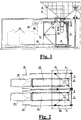
- Fig. 1 shows an embodiment of a unit for unitisation of bulk materials.
- the device according to the invention includes at least one such units, comprising container 1.
- the bulk material filling chute 2 is located on the roof of container 1, near the top wall opposite of the container door.
- the filling chute 2 is placed on the roof of container 1 using posts 3.
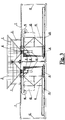
- Fig. 2 provides a top view, presenting two connected, parallel units for unitisation of bulk materials indicating that width of the filling chute 2 is bigger than the width of container 1. This prevents the bulk material loaded to the chute 2 using a dipper (not depicted), usually used in ports to unload bulk materials from vessels, from being spilled.
- a dipper not depicted
- the filling chute 2 includes a central discharge with a connector 7 terminated with an outlet tap 5.
- An electromechanic cut-off valve 6 is located between the connector 7 and the outlet tap 5.
- the cut-off valve 6 is provided as a butterfly valve.
- the main tube 8 terminated with the outlet chute 10 is placed below the cut-off valve 6, on the outlet tap 5.
- a weighing belt conveyor 9 is installed inside the container 1, under the outlet chute 10, on the floor of container 1.
- the weighing belt conveyor 9 cooperates with the filled unit packaging 11.
- the unit packaging 11 comprises a 500 kg big-bag.
- Other embodiments do not exclude use of bags with a different capacity.
- a separate belt conveyor 13 transferring filled unit packagings 11 towards the door area 12 of the container 1 is installed in the line of the weighing conveyor 9, on the floor of container 1, towards the door area 12 of the container 1.
- a side door 14 is installed in the side wall of container 1, enabling delivery and attachment of unit packagings 11 on the outlet chute 10.
- Fig. 1 schematically presents a unit packaging 11 attached to the outlet chute 10, as well as two filled unit packagings 11 on the belt conveyor 13. Filled unit packagings 11 may be placed within the collection station, picked up by their lifting lugs, for example using a stapler, and loaded onto vehicles for further transport.
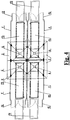
- Fig. 1 and Fig. 3 show, that in the case of this embodiment, the main pipe 8 with the outlet chute 10 is attached to the outlet tap 5.
- the bulk material leaves the outlet chute 10 under gravity to the discharge chute 2, and to the unit packaging 11.
- an air line 15 supplied by a fan 16 and provided with an air valve 17 is connected to the area between the outlet tap 5 and the main tube 8.
- a known electric control station 18 controls power supply provided to individual sub-units of the bulk material unitisation unit.
- Fig. 2 presents a device for unitisation of bulk materials, including two connected unitisation units in a parallel layout, wherein both units in the form of containers 1, equipped as the unit shown in Fig. 1 , are connected in parallel, by their side walls.
- Filling chutes 2 are in this case connected by their common edge, which means that the dipper (not shown) transferring the bulk material from the cargo space to chutes 2 does not have to release the bulk material precisely to a specific chute, but may fill both filling chutes 2 simultaneously, facilitating vessel unloading.
- the device including two connected unitisation units shown in Fig. 2 provides double the efficiency of the unitisation operation compared to a single unit. This makes unloading of bulk material from vessel twice as fast.
- Fig. 2 presents collection stations for filled unit packagings 19.
- the proposed bulk material unitisation unit in the form of a container also enables connection of two units into a single device in a serial layout.
- two units for unitisation of bulk materials in the form of containers are connected by their front walls, opposite to the container walls including doors 12.
- This figure presents a cross-section through both units, while doors 12 of the containers 1 are open.
- Individual sub-units are labelled in accordance with Fig. 1 .
- FIG. 4 A top view of another embodiment of the device according to the invention is presented in Fig. 4 .
- the device for unitisation of bulk materials includes four unitisation units. This embodiment of the device ensures efficiency four times higher than a single bulk material unitisation unit.
- two pairs of unitisation units, with each pair in the parallel layout, are connected by their top walls opposite to the doors of the containers 1, also comprise pairs of containers 1 in a serial layout.
- the filling chutes 2 in this embodiment are connected by their contacting edges, providing a large surface, onto which the bulk material may be loaded from the dipper (not shown in the figure), filling four discharges 4 of the filling chutes 2 simultaneously.
Abstract
Description
- The objective of the invention is a device for unitisation of bulk materials, used particularly during vessel unloading in ports. Unloading of vessels containing bulk materials is particularly cumbersome because of variable weather conditions and the haste, required in order to avoid high costs of vessel standstill at the unloading quay.
- Transport of goods includes, among other goods types, small goods and bulk goods. Small goods are usually understood as processed or ready products, which are provided with their unit packaging. In the case of these goods, it is possible to divide them into cargo units. Cargo units of small goods are often combined into collective packagings containing several units each.
- Bulk cargo is more effective in transport than small goods because of the fact that unit packagings do not take any additional space. However, bulk cargo delivered to its destination port must be divided into smaller parts, easier to handle during their further transport and shipment. The operation including division and packing of bulk goods is known as unitisation. Bulk goods transported loosely in cargo spaces of the vessel, such as for example coal, metal ores, bulk chemicals, like mineral fertilisers, cereals or gravel with different particle fractions must be unloaded from the cargo space of the bulk carrier vessel and then is usually transported in smaller batches, for example using ground means of transportation or barges, to a warehouse, where it is eventually unloaded. The warehouse is usually provided with devices enabling unitisation of such a material, namely packing such material in unit packagings. Thus, unloading of bulk materials usually requires the aforementioned, intermediate stage. Loading and unloading of bulk materials often use belt conveyors or systems with pneumatically operated ducts. Big-bags, often also known as container bags, are unit packagings used with bulk goods. Such bags enable bulk storage and transport because of the significant volume and capacity of a single bag, even exceeding one tonne. Such bags have been used for some time in transport of bulk materials.
- A number of devices for unitisation of bulk materials, namely for filling of the aforementioned, unit packagings, is known in the art. A solution disclosed in the patent document
EP 2889590 presents a method of filling bags with bulk products, including delivery of the first and of the second container to a loading station, followed by division of each container into two halves of their volume, wherein each of the halves is intended for feeding the product from the first or the second bag filling station. Then, the first measured quantity of the bulk good is delivered to the first container. The bag is then transferred to the first filling station and filled with the quantity of product from the first volume half of the first container. Then, the second, previously measured quantity of the product is delivered into the second container, the next measured quantity of the product is divided into two quantities, approximately equal to the half of the measured quantity, wherein each of the quantities is fed into the respective volume half of the second container. The bag is then moved to the second filling station. This is followed by alternate filling and topping of both bags, which, once filled, are transferred to the bag closing station and to the collection station. - Another solution known from the American patent document
US 4,467,845 , presents a method and a device for filling a flexible container with a bulk material, especially a fluidic material, using a filling pipe. The container is suspended in this case on a double cargo hook, whilst supporting on a supporting plate. Loops used to lift the container are tensioned during the entire filling operation. When the container is filled, the hook and the supporting plate are lowered simultaneously, and the plate is also shifted to a side, while the filling pipe is removed from the container. An external lever is then placed in the lifting loops, and afterwards the container may be removed from the filling device without the need to tilt the container. The device includes a double hook with a bottom section, which may be open, while the hook remains in the load carrying position. The hook is connected to a fixing device, which preferably detachably connected with a plate used to transfer the container. The position of this plate may change horizontally and vertically. - In another solution according to the British patent disclosure
GB 1505583 - Another known solution of a method and of a device for filling bags with bulk materials during unloading in a port is presented in a Chinese patent document no.
CN 1343607 . A system for handling bulk materials according to this known solution is provided with four unloading boxes, each of which is provided with two chutes. Two independent, electronic balances operate in two system lines. In the case of small bags, individual chutes are used to form four lines filling bags, and four vibrating units are used in this case. If large bags are filled, double chutes are used to create the bag filling line, together with two double vibrating units. A device according to this known solution, intended for loading and unloading bulk materials in a port, includes a tight lid, a filling basket with a material inlet, a chute, an electronic balance, an air compressor, control units controlling these devices, a bulk material container, a bag holder, a packing machine, a horizontal material conveyor and a working platform. The filling unit includes in this case a square, open filling basket, with its bottom part transforming into a system of four filling chutes. Each of the filling chutes in this solution is provided with two unloading openings. The filling buckets are respectively connected to four double-range, electronically controlled mobile plates equipped with automatic weighing devices provided as electronic balances. Each of the electronic balances includes a double sensor, synchronised with the bottom bolt located in the filling basket of the container. In this known solution, filling chutes include textile filters on metal frames, located above the opening of the outlet tap, under the filling chute, while crushing mills facilitating the flow of bulk material from the filling basket are located in the bottom part of the filling chute. - The objective of the invention is to develop a new design of a device for unloading bulk materials, particularly from a vessel at a port quay, combined with unitisation of such goods in order to avoid the costs of the intermediate step, including transport of smaller lots of such goods to an intermediate warehouse, equipped with devices for unitisation of this bulk material to container bags of the big-bag type. The objective of the invention is to develop a mobile structure device, enabling quick transport of the device to the side of another vessel mooring at another location within the port. The device should also enable simple expansion of its efficiency.
- The device for unitisation of bulk materials according to the invention includes at least one unit for unitisation of bulk material, with a bulk material filling chute installed on its roof. The filling chute is terminated with an inlet tap located inside the unitisation unit. A connector and an electromechanic valve cutting of the flow of the bulk material are located between the outlet of the filling chute and the outlet tap. A line feeding air to the unit packaging is attached to the outlet tap area.
- The unitisation unit according to the invention is characterised in that it is provided as a container, with the filling chute installed near the top wall located against the door of the container, while a weighing belt conveyor is installed inside the container, underneath the outlet chute, on the floor of the container. The weighing belt conveyor cooperates with the filled unit packaging, wherein a separate belt conveyor is installed on the floor of the container, leading to the direction of the container door area, transferring filled unit packagings towards the container door area. A side door is provided in the side wall of the container.
- According to the invention, a main pipe with an outlet chute leading to the unit packaging is preferably affixed to the outlet tap, wherein an air line supplied from a fan and provided with a valve is attached to the area between the outlet tap and the main pipe.
- The device for unitisation may include two unitisation units provided as a pair of connected containers provided with two filling chutes, connected by their common edge.
- The unitisation units provided as containers may be connected by their side walls in a parallel layout, with doors of the containers facing the same direction.
- Unitisation units provided as containers may be connected by their rear walls in a serial layout, with doors of the containers facing the opposite direction.
- The device for unitisation, including two connected containers, may include two filling chutes connected at the edge, forming a rectangle in the top view, with two outlet taps.
- In another preferable embodiment of the invention, the devices for unitisation of bulk materials may include two container pairs in a parallel layout, connected by rear walls, forming two pairs of containers in a serial layout, with one pair of containers in a serial layout may be connected by their side walls with the second pair of containers.
- In an embodiment of the device according to the invention, provided as four containers, four filling chutes are preferably connected by their neighbouring edges, forming a rectangle with four outlet taps in the top view.
- A novel design of the device for unloading bulk materials was developed, particularly for unloading bulk materials from a vessel at a port quay, with simultaneous unitisation of the unloaded bulk materials in order to avoid the costs of the intermediate stages, including transport of smaller lots of the material to an intermediate warehouse equipped with devices for unitisation of this bulk material into container bags of the big-bag type. A device comprising at least one container was developed, improving mobility of the device. In the case of a device with a container used as its external outline, it could be quickly transferred next to the side of another vessel mooring at another location within the port or at another port.
- The device also enables simple options of expanding its capacity by adding and combining individual devices with the same, unified dimensions of the container. Doubling the number of unitisation units results in doubling the weight of unitised bulk material in a time unit. Twice as many unit packagings, for example big-bags, may be filled during a time unit. In the case of a unitisation device including four connected container units, the efficiency of unitisation, and thus the unloading rate, may increase four times.
- At the same time, as neighbouring filling chutes located above the connected containers are connected by their common edges, the rate of unloading a vessel at the quay may be increased without the fear of losing a part of the cargo, which is usually collected from the cargo space of the vessel using a dipper.
- Within a single cycle, a previously formed big-bag adapted to bulk material acceptance is filled with air supplied by a fan. After the desired weight is reached on the weighing conveyor, the conveyor transfers the filled bag to the second belt conveyor removing the filled bag. In the next cycle, another big-bag is filled and again transferred onto the belt conveyor removing filled unit packagings outside the device for unitisation, to the collection station.
- The object of the invention is presented as embodiments in the attached drawing, in which individual figures present the following:
- Fig. 1 -
- a cross-section through the unitisation unit.
- Fig. 2 -
- a top view of the device for unitisation provided as two unitisation units connected in a parallel layout.
- Fig. 3 -
- a cross-section through the device for unitisation in the form of two unitisation units connected in a parallel layout.
- Fig. 4 -
- a top view of the device for unitisation in the form of two connected pairs of unitisation units.
-
Fig. 1 shows an embodiment of a unit for unitisation of bulk materials. The device according to the invention includes at least one such units, comprisingcontainer 1. The bulkmaterial filling chute 2 is located on the roof ofcontainer 1, near the top wall opposite of the container door. The fillingchute 2 is placed on the roof ofcontainer 1 usingposts 3.Fig. 2 provides a top view, presenting two connected, parallel units for unitisation of bulk materials indicating that width of the fillingchute 2 is bigger than the width ofcontainer 1. This prevents the bulk material loaded to thechute 2 using a dipper (not depicted), usually used in ports to unload bulk materials from vessels, from being spilled. - The filling
chute 2 includes a central discharge with a connector 7 terminated with anoutlet tap 5. An electromechanic cut-off valve 6 is located between the connector 7 and theoutlet tap 5. In these embodiments, the cut-off valve 6 is provided as a butterfly valve. Themain tube 8 terminated with theoutlet chute 10 is placed below the cut-off valve 6, on theoutlet tap 5. - A weighing
belt conveyor 9 is installed inside thecontainer 1, under theoutlet chute 10, on the floor ofcontainer 1. The weighingbelt conveyor 9 cooperates with the filledunit packaging 11. In this embodiment, theunit packaging 11 comprises a 500 kg big-bag. Other embodiments do not exclude use of bags with a different capacity. Aseparate belt conveyor 13 transferring filled unit packagings 11 towards thedoor area 12 of thecontainer 1 is installed in the line of the weighingconveyor 9, on the floor ofcontainer 1, towards thedoor area 12 of thecontainer 1. Aside door 14 is installed in the side wall ofcontainer 1, enabling delivery and attachment of unit packagings 11 on theoutlet chute 10.Fig. 1 schematically presents aunit packaging 11 attached to theoutlet chute 10, as well as two filled unit packagings 11 on thebelt conveyor 13. Filled unit packagings 11 may be placed within the collection station, picked up by their lifting lugs, for example using a stapler, and loaded onto vehicles for further transport. -
Fig. 1 andFig. 3 show, that in the case of this embodiment, themain pipe 8 with theoutlet chute 10 is attached to theoutlet tap 5. The bulk material leaves theoutlet chute 10 under gravity to thedischarge chute 2, and to theunit packaging 11. As shown in these Figures, anair line 15 supplied by afan 16 and provided with anair valve 17 is connected to the area between theoutlet tap 5 and themain tube 8. A knownelectric control station 18 controls power supply provided to individual sub-units of the bulk material unitisation unit. -
Fig. 2 presents a device for unitisation of bulk materials, including two connected unitisation units in a parallel layout, wherein both units in the form ofcontainers 1, equipped as the unit shown inFig. 1 , are connected in parallel, by their side walls. Fillingchutes 2 are in this case connected by their common edge, which means that the dipper (not shown) transferring the bulk material from the cargo space tochutes 2 does not have to release the bulk material precisely to a specific chute, but may fill both fillingchutes 2 simultaneously, facilitating vessel unloading. The device including two connected unitisation units shown inFig. 2 , provides double the efficiency of the unitisation operation compared to a single unit. This makes unloading of bulk material from vessel twice as fast.Fig. 2 presents collection stations for filledunit packagings 19. - The proposed bulk material unitisation unit in the form of a container also enables connection of two units into a single device in a serial layout. This is shown in another embodiment in
Fig. 3 . According to this embodiment of the invention, two units for unitisation of bulk materials in the form of containers are connected by their front walls, opposite to the containerwalls including doors 12. This figure presents a cross-section through both units, whiledoors 12 of thecontainers 1 are open. Individual sub-units are labelled in accordance withFig. 1 . - A top view of another embodiment of the device according to the invention is presented in
Fig. 4 . In this embodiment, the device for unitisation of bulk materials includes four unitisation units. This embodiment of the device ensures efficiency four times higher than a single bulk material unitisation unit. In this embodiment, two pairs of unitisation units, with each pair in the parallel layout, are connected by their top walls opposite to the doors of thecontainers 1, also comprise pairs ofcontainers 1 in a serial layout. The fillingchutes 2 in this embodiment are connected by their contacting edges, providing a large surface, onto which the bulk material may be loaded from the dipper (not shown in the figure), filling fourdischarges 4 of the fillingchutes 2 simultaneously. -
- 1.
- Container.
- 2.
- Filling chute.
- 3.
- Post.
- 4.
- Chute discharge.
- 5.
- Outlet type.
- 6.
- Cut-off valve.
- 7.
- Connector.
- 8.
- Main tube.
- 9.
- Weighing belt conveyor.
- 10.
- Outlet chute.
- 11.
- Unit packaging.
- 12.
- Container door.
- 13.
- Belt conveyor.
- 14.
- Side door.
- 15.
- Air line.
- 16.
- Fan.
- 17.
- Air valve.
- 18.
- Control station.
- 19.
- Collection station.
Claims (8)
- A device for unitisation of bulk materials, including at least one unit for unitisation of bulk materials, on the roof of which a bulk material filling chute terminated with an outlet tap located inside the unitisation unit is attached, wherein a connector and an electromechanical valve are located between the outlet of the filling chute and the outlet tap, while an air line supplying air to the unit packaging is attached to the outlet tap area, characterised in that the unitisation unit comprises a container (1) wherein the filling chute (2) is installed near the top wall opposite the door (12) of the container, while a weighing belt conveyor (9) is located inside the container (1), under the outlet chute (10) on the floor of the container (1), which cooperates with the filled unit packaging (11), wherein a separate belt conveyor (13) is installed on the floor of the conveyor (1), leading to the door area, transferring filled unit packagings (11) towards the door area (12) of the container (1), while the side door of the container (1) includes a side door (13).
- A device for unitisation according to claim 1, characterised in that a tube (8) with an outlet chute (10) is installed on the outlet tap (5) and leading to the packaging unit (11), wherein an air line (15) supplied by a fan (16) and provided with an air valve (17) is attached to the area between the outlet tap (5) and the tube (8).
- A device for unitisation according to claim 1, characterised in that it includes two unitisation units provided as a connected pair of containers (1) provided with two filling chutes (2) connected by a common edge.
- A device for unitisation according to claim 3, characterised in that containers (1) are connected by their side walls in a parallel layout, with doors (12) of containers (1) facing the same direction.
- A device for unitisation according to claim 3, characterised in that containers (1) are connected by their rear walls in a serial layout, with doors (12) of the containers (1) facing opposite directions.
- A device for unitisation according to claim 4 or 5, characterised in that two filling chutes (2) are connected by their edge, forming a rectangle with two outlet taps (4) for bulk material in the top view.
- A device for unitisation according to claim 4 or 5, characterised in that it is formed by two pairs of containers (1) in a parallel layout, connected by their rear walls, simultaneously forming two pairs of containers (1) in a serial layout, with one container pair connected to the other container pair by their side walls.
- A device for unitisation according to claim 7, characterised in that four filling chutes (2) are connected by their neighbouring edges, forming a rectangle with four outlets (4) of the bulk material in the top view.
Applications Claiming Priority (1)
| Application Number | Priority Date | Filing Date | Title |
|---|---|---|---|
| PL424777A PL234830B1 (en) | 2018-03-06 | 2018-03-06 | Device for unitization of bulk materials |
Publications (2)
| Publication Number | Publication Date |
|---|---|
| EP3536622A1 true EP3536622A1 (en) | 2019-09-11 |
| EP3536622B1 EP3536622B1 (en) | 2020-11-25 |
Family
ID=66676467
Family Applications (1)
| Application Number | Title | Priority Date | Filing Date |
|---|---|---|---|
| EP19460009.4A Active EP3536622B1 (en) | 2018-03-06 | 2019-02-15 | Device for unitisation of bulk materials |
Country Status (2)
| Country | Link |
|---|---|
| EP (1) | EP3536622B1 (en) |
| PL (1) | PL234830B1 (en) |
Citations (7)
| Publication number | Priority date | Publication date | Assignee | Title |
|---|---|---|---|---|
| GB1505583A (en) | 1974-06-11 | 1978-03-30 | Norsk Hydro As | Method for filling free-flowing bulk material into large sacks |
| EP0051484A1 (en) * | 1980-11-04 | 1982-05-12 | Blendlock Limited | A method of and apparatus for bagging granular or pulverulent materials |
| GB2100014A (en) * | 1981-06-10 | 1982-12-15 | Nat Shipping Bagging Services | Transportation of free-flowing material |
| US4467845A (en) | 1981-04-30 | 1984-08-28 | Norsk Hydro A.S. | Method and means for filling of bulk material in flexible containers |
| US4825913A (en) * | 1986-08-28 | 1989-05-02 | Leslie Stott | Powder dispensing apparatus |
| CN1343607A (en) | 2001-01-22 | 2002-04-10 | 天津港第二港埠有限公司 | Method and apparatus for pouring bulk material in bags at port |
| EP2889590A1 (en) | 2013-12-27 | 2015-07-01 | Concetti S.p.A. | Method for filling bags with a metered quantity of bulk material, apparatus and automatic machine for implementing the method |
Family Cites Families (1)
| Publication number | Priority date | Publication date | Assignee | Title |
|---|---|---|---|---|
| US2548222A (en) * | 1946-03-04 | 1951-04-10 | Bemis Bro Bag Co | Apparatus for filling bags |
-
2018
- 2018-03-06 PL PL424777A patent/PL234830B1/en unknown
-
2019
- 2019-02-15 EP EP19460009.4A patent/EP3536622B1/en active Active
Patent Citations (7)
| Publication number | Priority date | Publication date | Assignee | Title |
|---|---|---|---|---|
| GB1505583A (en) | 1974-06-11 | 1978-03-30 | Norsk Hydro As | Method for filling free-flowing bulk material into large sacks |
| EP0051484A1 (en) * | 1980-11-04 | 1982-05-12 | Blendlock Limited | A method of and apparatus for bagging granular or pulverulent materials |
| US4467845A (en) | 1981-04-30 | 1984-08-28 | Norsk Hydro A.S. | Method and means for filling of bulk material in flexible containers |
| GB2100014A (en) * | 1981-06-10 | 1982-12-15 | Nat Shipping Bagging Services | Transportation of free-flowing material |
| US4825913A (en) * | 1986-08-28 | 1989-05-02 | Leslie Stott | Powder dispensing apparatus |
| CN1343607A (en) | 2001-01-22 | 2002-04-10 | 天津港第二港埠有限公司 | Method and apparatus for pouring bulk material in bags at port |
| EP2889590A1 (en) | 2013-12-27 | 2015-07-01 | Concetti S.p.A. | Method for filling bags with a metered quantity of bulk material, apparatus and automatic machine for implementing the method |
Also Published As
| Publication number | Publication date |
|---|---|
| EP3536622B1 (en) | 2020-11-25 |
| PL234830B1 (en) | 2020-04-30 |
| PL424777A1 (en) | 2019-09-09 |
Similar Documents
| Publication | Publication Date | Title |
|---|---|---|
| US3314557A (en) | Tank type bulk blending plant | |
| US20080050211A1 (en) | Continuous bulk bag discharging facility | |
| US20070193854A1 (en) | Gateless modular conveyor distribution system | |
| KR102154171B1 (en) | Powder batch processing system | |
| CN206664969U (en) | A kind of raw material conveying device | |
| CN106672643A (en) | Bulk material storage yard automatic warehouse discharge system | |
| CN110386439B (en) | Sorting unloader and method for unloading and sorting packages provided in containers | |
| FI73181C (en) | Sacking device and distribution procedure for sacking of free-flowing material. | |
| CN110422348A (en) | Jumbo bag automatic bag feeding bottle placer | |
| CN214190957U (en) | Coke loading and unloading hopper | |
| EP3536622A1 (en) | Device for unitisation of bulk materials | |
| CN210940010U (en) | Full-automatic dispensing equipment of PP particle | |
| CN202321647U (en) | Unloading system for logistics-model dilute-phase gas in inner lining bag of container | |
| US4225001A (en) | Bagging machine with two weighing scales and two reversible conveyors | |
| CN101687554B (en) | Packing machine | |
| US2767030A (en) | Apparatus for conveying pulverulent material in fixed installations | |
| EP0886766B1 (en) | Combinatorial weighing apparatus | |
| US20160200503A1 (en) | Intermodal bulk aggregate container | |
| CN108349665A (en) | The cargo elevator of cargo transfer means for automatic cargo storage system | |
| CN107986040B (en) | A transportation delivery system for starch | |
| WO2005030622A1 (en) | A method and system for filling the entire volume of 20 feet steel shipping containers | |
| CN206265907U (en) | A kind of material handling system | |
| CN219770377U (en) | Powder unpacking and feeding system | |
| HRP20220092T1 (en) | System and method for loading, transporting and unloading frangible products | |
| CN208201147U (en) | The container alumina blanking system of fast blanking |
Legal Events
| Date | Code | Title | Description |
|---|---|---|---|
| PUAI | Public reference made under article 153(3) epc to a published international application that has entered the european phase |
Free format text: ORIGINAL CODE: 0009012 |
|
| STAA | Information on the status of an ep patent application or granted ep patent |
Free format text: STATUS: THE APPLICATION HAS BEEN PUBLISHED |
|
| AK | Designated contracting states |
Kind code of ref document: A1 Designated state(s): AL AT BE BG CH CY CZ DE DK EE ES FI FR GB GR HR HU IE IS IT LI LT LU LV MC MK MT NL NO PL PT RO RS SE SI SK SM TR |
|
| AX | Request for extension of the european patent |
Extension state: BA ME |
|
| STAA | Information on the status of an ep patent application or granted ep patent |
Free format text: STATUS: REQUEST FOR EXAMINATION WAS MADE |
|
| 17P | Request for examination filed |
Effective date: 20200309 |
|
| RBV | Designated contracting states (corrected) |
Designated state(s): AL AT BE BG CH CY CZ DE DK EE ES FI FR GB GR HR HU IE IS IT LI LT LU LV MC MK MT NL NO PL PT RO RS SE SI SK SM TR |
|
| GRAP | Despatch of communication of intention to grant a patent |
Free format text: ORIGINAL CODE: EPIDOSNIGR1 |
|
| STAA | Information on the status of an ep patent application or granted ep patent |
Free format text: STATUS: GRANT OF PATENT IS INTENDED |
|
| RIC1 | Information provided on ipc code assigned before grant |
Ipc: B65B 61/28 20060101AFI20200717BHEP Ipc: B65B 1/32 20060101ALI20200717BHEP Ipc: B65D 90/00 20060101ALN20200717BHEP Ipc: B65D 88/54 20060101ALI20200717BHEP Ipc: B65B 39/00 20060101ALN20200717BHEP Ipc: B65B 1/06 20060101ALI20200717BHEP Ipc: B65B 39/04 20060101ALI20200717BHEP Ipc: B65B 65/00 20060101ALI20200717BHEP |
|
| INTG | Intention to grant announced |
Effective date: 20200811 |
|
| GRAS | Grant fee paid |
Free format text: ORIGINAL CODE: EPIDOSNIGR3 |
|
| GRAA | (expected) grant |
Free format text: ORIGINAL CODE: 0009210 |
|
| STAA | Information on the status of an ep patent application or granted ep patent |
Free format text: STATUS: THE PATENT HAS BEEN GRANTED |
|
| AK | Designated contracting states |
Kind code of ref document: B1 Designated state(s): AL AT BE BG CH CY CZ DE DK EE ES FI FR GB GR HR HU IE IS IT LI LT LU LV MC MK MT NL NO PL PT RO RS SE SI SK SM TR |
|
| REG | Reference to a national code |
Ref country code: GB Ref legal event code: FG4D |
|
| REG | Reference to a national code |
Ref country code: CH Ref legal event code: EP |
|
| REG | Reference to a national code |
Ref country code: AT Ref legal event code: REF Ref document number: 1338027 Country of ref document: AT Kind code of ref document: T Effective date: 20201215 |
|
| REG | Reference to a national code |
Ref country code: DE Ref legal event code: R096 Ref document number: 602019001481 Country of ref document: DE |
|
| REG | Reference to a national code |
Ref country code: IE Ref legal event code: FG4D |
|
| REG | Reference to a national code |
Ref country code: AT Ref legal event code: MK05 Ref document number: 1338027 Country of ref document: AT Kind code of ref document: T Effective date: 20201125 |
|
| REG | Reference to a national code |
Ref country code: NL Ref legal event code: MP Effective date: 20201125 |
|
| PG25 | Lapsed in a contracting state [announced via postgrant information from national office to epo] |
Ref country code: FI Free format text: LAPSE BECAUSE OF FAILURE TO SUBMIT A TRANSLATION OF THE DESCRIPTION OR TO PAY THE FEE WITHIN THE PRESCRIBED TIME-LIMIT Effective date: 20201125 Ref country code: PT Free format text: LAPSE BECAUSE OF FAILURE TO SUBMIT A TRANSLATION OF THE DESCRIPTION OR TO PAY THE FEE WITHIN THE PRESCRIBED TIME-LIMIT Effective date: 20210325 Ref country code: RS Free format text: LAPSE BECAUSE OF FAILURE TO SUBMIT A TRANSLATION OF THE DESCRIPTION OR TO PAY THE FEE WITHIN THE PRESCRIBED TIME-LIMIT Effective date: 20201125 Ref country code: NO Free format text: LAPSE BECAUSE OF FAILURE TO SUBMIT A TRANSLATION OF THE DESCRIPTION OR TO PAY THE FEE WITHIN THE PRESCRIBED TIME-LIMIT Effective date: 20210225 Ref country code: GR Free format text: LAPSE BECAUSE OF FAILURE TO SUBMIT A TRANSLATION OF THE DESCRIPTION OR TO PAY THE FEE WITHIN THE PRESCRIBED TIME-LIMIT Effective date: 20210226 |
|
| PG25 | Lapsed in a contracting state [announced via postgrant information from national office to epo] |
Ref country code: AT Free format text: LAPSE BECAUSE OF FAILURE TO SUBMIT A TRANSLATION OF THE DESCRIPTION OR TO PAY THE FEE WITHIN THE PRESCRIBED TIME-LIMIT Effective date: 20201125 Ref country code: LV Free format text: LAPSE BECAUSE OF FAILURE TO SUBMIT A TRANSLATION OF THE DESCRIPTION OR TO PAY THE FEE WITHIN THE PRESCRIBED TIME-LIMIT Effective date: 20201125 Ref country code: IS Free format text: LAPSE BECAUSE OF FAILURE TO SUBMIT A TRANSLATION OF THE DESCRIPTION OR TO PAY THE FEE WITHIN THE PRESCRIBED TIME-LIMIT Effective date: 20210325 Ref country code: PL Free format text: LAPSE BECAUSE OF FAILURE TO SUBMIT A TRANSLATION OF THE DESCRIPTION OR TO PAY THE FEE WITHIN THE PRESCRIBED TIME-LIMIT Effective date: 20201125 Ref country code: SE Free format text: LAPSE BECAUSE OF FAILURE TO SUBMIT A TRANSLATION OF THE DESCRIPTION OR TO PAY THE FEE WITHIN THE PRESCRIBED TIME-LIMIT Effective date: 20201125 Ref country code: BG Free format text: LAPSE BECAUSE OF FAILURE TO SUBMIT A TRANSLATION OF THE DESCRIPTION OR TO PAY THE FEE WITHIN THE PRESCRIBED TIME-LIMIT Effective date: 20210225 |
|
| REG | Reference to a national code |
Ref country code: LT Ref legal event code: MG9D |
|
| PG25 | Lapsed in a contracting state [announced via postgrant information from national office to epo] |
Ref country code: HR Free format text: LAPSE BECAUSE OF FAILURE TO SUBMIT A TRANSLATION OF THE DESCRIPTION OR TO PAY THE FEE WITHIN THE PRESCRIBED TIME-LIMIT Effective date: 20201125 |
|
| PG25 | Lapsed in a contracting state [announced via postgrant information from national office to epo] |
Ref country code: CZ Free format text: LAPSE BECAUSE OF FAILURE TO SUBMIT A TRANSLATION OF THE DESCRIPTION OR TO PAY THE FEE WITHIN THE PRESCRIBED TIME-LIMIT Effective date: 20201125 Ref country code: EE Free format text: LAPSE BECAUSE OF FAILURE TO SUBMIT A TRANSLATION OF THE DESCRIPTION OR TO PAY THE FEE WITHIN THE PRESCRIBED TIME-LIMIT Effective date: 20201125 Ref country code: SM Free format text: LAPSE BECAUSE OF FAILURE TO SUBMIT A TRANSLATION OF THE DESCRIPTION OR TO PAY THE FEE WITHIN THE PRESCRIBED TIME-LIMIT Effective date: 20201125 Ref country code: SK Free format text: LAPSE BECAUSE OF FAILURE TO SUBMIT A TRANSLATION OF THE DESCRIPTION OR TO PAY THE FEE WITHIN THE PRESCRIBED TIME-LIMIT Effective date: 20201125 Ref country code: RO Free format text: LAPSE BECAUSE OF FAILURE TO SUBMIT A TRANSLATION OF THE DESCRIPTION OR TO PAY THE FEE WITHIN THE PRESCRIBED TIME-LIMIT Effective date: 20201125 Ref country code: LT Free format text: LAPSE BECAUSE OF FAILURE TO SUBMIT A TRANSLATION OF THE DESCRIPTION OR TO PAY THE FEE WITHIN THE PRESCRIBED TIME-LIMIT Effective date: 20201125 |
|
| REG | Reference to a national code |
Ref country code: DE Ref legal event code: R097 Ref document number: 602019001481 Country of ref document: DE |
|
| PG25 | Lapsed in a contracting state [announced via postgrant information from national office to epo] |
Ref country code: DK Free format text: LAPSE BECAUSE OF FAILURE TO SUBMIT A TRANSLATION OF THE DESCRIPTION OR TO PAY THE FEE WITHIN THE PRESCRIBED TIME-LIMIT Effective date: 20201125 |
|
| REG | Reference to a national code |
Ref country code: DE Ref legal event code: R119 Ref document number: 602019001481 Country of ref document: DE |
|
| PG25 | Lapsed in a contracting state [announced via postgrant information from national office to epo] |
Ref country code: MC Free format text: LAPSE BECAUSE OF FAILURE TO SUBMIT A TRANSLATION OF THE DESCRIPTION OR TO PAY THE FEE WITHIN THE PRESCRIBED TIME-LIMIT Effective date: 20201125 |
|
| PLBE | No opposition filed within time limit |
Free format text: ORIGINAL CODE: 0009261 |
|
| STAA | Information on the status of an ep patent application or granted ep patent |
Free format text: STATUS: NO OPPOSITION FILED WITHIN TIME LIMIT |
|
| REG | Reference to a national code |
Ref country code: BE Ref legal event code: MM Effective date: 20210228 |
|
| PG25 | Lapsed in a contracting state [announced via postgrant information from national office to epo] |
Ref country code: LU Free format text: LAPSE BECAUSE OF NON-PAYMENT OF DUE FEES Effective date: 20210215 Ref country code: IT Free format text: LAPSE BECAUSE OF FAILURE TO SUBMIT A TRANSLATION OF THE DESCRIPTION OR TO PAY THE FEE WITHIN THE PRESCRIBED TIME-LIMIT Effective date: 20201125 Ref country code: NL Free format text: LAPSE BECAUSE OF FAILURE TO SUBMIT A TRANSLATION OF THE DESCRIPTION OR TO PAY THE FEE WITHIN THE PRESCRIBED TIME-LIMIT Effective date: 20201125 Ref country code: AL Free format text: LAPSE BECAUSE OF FAILURE TO SUBMIT A TRANSLATION OF THE DESCRIPTION OR TO PAY THE FEE WITHIN THE PRESCRIBED TIME-LIMIT Effective date: 20201125 |
|
| 26N | No opposition filed |
Effective date: 20210826 |
|
| PG25 | Lapsed in a contracting state [announced via postgrant information from national office to epo] |
Ref country code: SI Free format text: LAPSE BECAUSE OF FAILURE TO SUBMIT A TRANSLATION OF THE DESCRIPTION OR TO PAY THE FEE WITHIN THE PRESCRIBED TIME-LIMIT Effective date: 20201125 |
|
| PG25 | Lapsed in a contracting state [announced via postgrant information from national office to epo] |
Ref country code: ES Free format text: LAPSE BECAUSE OF FAILURE TO SUBMIT A TRANSLATION OF THE DESCRIPTION OR TO PAY THE FEE WITHIN THE PRESCRIBED TIME-LIMIT Effective date: 20201125 Ref country code: FR Free format text: LAPSE BECAUSE OF NON-PAYMENT OF DUE FEES Effective date: 20210228 Ref country code: DE Free format text: LAPSE BECAUSE OF NON-PAYMENT OF DUE FEES Effective date: 20210901 Ref country code: IE Free format text: LAPSE BECAUSE OF NON-PAYMENT OF DUE FEES Effective date: 20210215 |
|
| PG25 | Lapsed in a contracting state [announced via postgrant information from national office to epo] |
Ref country code: IS Free format text: LAPSE BECAUSE OF FAILURE TO SUBMIT A TRANSLATION OF THE DESCRIPTION OR TO PAY THE FEE WITHIN THE PRESCRIBED TIME-LIMIT Effective date: 20210325 |
|
| PG25 | Lapsed in a contracting state [announced via postgrant information from national office to epo] |
Ref country code: BE Free format text: LAPSE BECAUSE OF NON-PAYMENT OF DUE FEES Effective date: 20210228 |
|
| REG | Reference to a national code |
Ref country code: CH Ref legal event code: PL |
|
| PG25 | Lapsed in a contracting state [announced via postgrant information from national office to epo] |
Ref country code: LI Free format text: LAPSE BECAUSE OF NON-PAYMENT OF DUE FEES Effective date: 20220228 Ref country code: CH Free format text: LAPSE BECAUSE OF NON-PAYMENT OF DUE FEES Effective date: 20220228 |
|
| PG25 | Lapsed in a contracting state [announced via postgrant information from national office to epo] |
Ref country code: CY Free format text: LAPSE BECAUSE OF FAILURE TO SUBMIT A TRANSLATION OF THE DESCRIPTION OR TO PAY THE FEE WITHIN THE PRESCRIBED TIME-LIMIT Effective date: 20201125 |
|
| PG25 | Lapsed in a contracting state [announced via postgrant information from national office to epo] |
Ref country code: HU Free format text: LAPSE BECAUSE OF FAILURE TO SUBMIT A TRANSLATION OF THE DESCRIPTION OR TO PAY THE FEE WITHIN THE PRESCRIBED TIME-LIMIT; INVALID AB INITIO Effective date: 20190215 |
|
| GBPC | Gb: european patent ceased through non-payment of renewal fee |
Effective date: 20230215 |
|
| PG25 | Lapsed in a contracting state [announced via postgrant information from national office to epo] |
Ref country code: GB Free format text: LAPSE BECAUSE OF NON-PAYMENT OF DUE FEES Effective date: 20230215 |
|
| PG25 | Lapsed in a contracting state [announced via postgrant information from national office to epo] |
Ref country code: GB Free format text: LAPSE BECAUSE OF NON-PAYMENT OF DUE FEES Effective date: 20230215 |