EP3536611A1 - Rotor for a hover-capable aircraft and related method of control - Google Patents
Rotor for a hover-capable aircraft and related method of control Download PDFInfo
- Publication number
- EP3536611A1 EP3536611A1 EP19171701.6A EP19171701A EP3536611A1 EP 3536611 A1 EP3536611 A1 EP 3536611A1 EP 19171701 A EP19171701 A EP 19171701A EP 3536611 A1 EP3536611 A1 EP 3536611A1
- Authority
- EP
- European Patent Office
- Prior art keywords
- axis
- tip portion
- respect
- blade
- main portion
- Prior art date
- Legal status (The legal status is an assumption and is not a legal conclusion. Google has not performed a legal analysis and makes no representation as to the accuracy of the status listed.)
- Granted
Links
Images






Classifications
-
- B—PERFORMING OPERATIONS; TRANSPORTING
- B64—AIRCRAFT; AVIATION; COSMONAUTICS
- B64C—AEROPLANES; HELICOPTERS
- B64C27/00—Rotorcraft; Rotors peculiar thereto
- B64C27/32—Rotors
- B64C27/46—Blades
-
- B—PERFORMING OPERATIONS; TRANSPORTING
- B64—AIRCRAFT; AVIATION; COSMONAUTICS
- B64C—AEROPLANES; HELICOPTERS
- B64C27/00—Rotorcraft; Rotors peculiar thereto
- B64C27/32—Rotors
- B64C27/46—Blades
- B64C27/463—Blade tips
-
- B—PERFORMING OPERATIONS; TRANSPORTING
- B64—AIRCRAFT; AVIATION; COSMONAUTICS
- B64C—AEROPLANES; HELICOPTERS
- B64C27/00—Rotorcraft; Rotors peculiar thereto
- B64C27/04—Helicopters
-
- B—PERFORMING OPERATIONS; TRANSPORTING
- B64—AIRCRAFT; AVIATION; COSMONAUTICS
- B64C—AEROPLANES; HELICOPTERS
- B64C27/00—Rotorcraft; Rotors peculiar thereto
- B64C27/54—Mechanisms for controlling blade adjustment or movement relative to rotor head, e.g. lag-lead movement
- B64C27/58—Transmitting means, e.g. interrelated with initiating means or means acting on blades
- B64C27/59—Transmitting means, e.g. interrelated with initiating means or means acting on blades mechanical
-
- B—PERFORMING OPERATIONS; TRANSPORTING
- B64—AIRCRAFT; AVIATION; COSMONAUTICS
- B64C—AEROPLANES; HELICOPTERS
- B64C27/00—Rotorcraft; Rotors peculiar thereto
- B64C27/54—Mechanisms for controlling blade adjustment or movement relative to rotor head, e.g. lag-lead movement
- B64C27/72—Means acting on blades
-
- B—PERFORMING OPERATIONS; TRANSPORTING
- B64—AIRCRAFT; AVIATION; COSMONAUTICS
- B64C—AEROPLANES; HELICOPTERS
- B64C27/00—Rotorcraft; Rotors peculiar thereto
- B64C27/54—Mechanisms for controlling blade adjustment or movement relative to rotor head, e.g. lag-lead movement
- B64C27/72—Means acting on blades
- B64C2027/7205—Means acting on blades on each blade individually, e.g. individual blade control [IBC]
- B64C2027/7211—Means acting on blades on each blade individually, e.g. individual blade control [IBC] without flaps
-
- Y—GENERAL TAGGING OF NEW TECHNOLOGICAL DEVELOPMENTS; GENERAL TAGGING OF CROSS-SECTIONAL TECHNOLOGIES SPANNING OVER SEVERAL SECTIONS OF THE IPC; TECHNICAL SUBJECTS COVERED BY FORMER USPC CROSS-REFERENCE ART COLLECTIONS [XRACs] AND DIGESTS
- Y02—TECHNOLOGIES OR APPLICATIONS FOR MITIGATION OR ADAPTATION AGAINST CLIMATE CHANGE
- Y02T—CLIMATE CHANGE MITIGATION TECHNOLOGIES RELATED TO TRANSPORTATION
- Y02T50/00—Aeronautics or air transport
- Y02T50/60—Efficient propulsion technologies, e.g. for aircraft
Definitions
- the present invention relates to a rotor for a hover-capable aircraft.
- the present invention also relates to a method of controlling a rotor for a hover-capable aircraft.
- Known hover-capable aircrafts such as helicopters for example, comprise a fuselage, a main rotor positioned on the top of a central portion of the fuselage and an anti-torque tail rotor with the function of countering the torque generated by the main rotor on the fuselage.
- the main rotor basically comprises a mast rotatable about an axis, a hub coupled to this mast, and a plurality of blades fastened in a cantilever manner to the above-mentioned hub.
- each blade has a substantially longitudinal extension radial to the axis of the mast and, in use, is driven in rotation by the hub on a motion plane transversal to the axis of the mast.
- each blade is movable with respect to the hub on some or all of the orientation planes so as to enable the different manoeuvres of the helicopter.
- Each blade comprises, in particular:
- each blade is longer than the corresponding tip portion.
- the tip portions of the blades In the helicopter industry, it is known to shape the tip portions of the blades with an anhedral (negative dihedral) angle with respect to the corresponding main portions. In other words, the tip portions of the blades are inclined downwards from the corresponding main portions and towards the fuselage of the helicopter.
- US2016/0075430 describes a rotor for a hover-capable aircraft in which each blade of the rotor comprises a tip portion hinged to a main root portion, and which can be operated to adjust the anhedral angle according to the flight conditions of the aircraft.
- the rotor shown in US2016/0075430 further comprises a hydraulic actuator for adjusting the anhedral angle of the tip portion.
- the tip portions are subjected to very high aerodynamic and inertial loads, in particular centrifugal forces. Accordingly, the actuating system requires very powerful actuating forces and torques.
- KR-A-20120059091 discloses a known rotor.
- EP-A-1127786 discloses a base wing, which is attached at its root end portion to the rotor head of a rotational drive unit and is provided with a front wing and a rear wing having substantially equal spans.
- EP-A-1127786 discloses a control unit for controlling the incidence angle of the front and rear wings.
- EP-A-1127786 discloses a rotor for a hover-capable aircraft according to the preamble of claim 1 and a method of controlling a rotor for a hover-capable aircraft according to the preamble of claim 9.
- US-A-2006/027703 discloses a blade comprising a main portion, a tip portion having an aerodynamic shape and positioned proximate to an edge of the main portion, an actuator coupled to the tip portion.
- the actuator is configured to rotate the tip portion about a longitudinal axis thereof and to adjust a dihedral angle of the tip portion.
- EP-A-2228299 discloses a known rotor for a hover-capable aircraft.
- the object of the present invention is to produce a rotor for an aircraft capable of hovering that satisfies at least one of the above-specified needs in a simple and inexpensive manner.
- the aforesaid object is achieved by the present invention, in so far as it relates to a rotor for a hover-capable aircraft, as claimed in claim 1.
- the present invention also relates to a method of controlling a rotor for a hover-capable aircraft, as claimed in claim 9.
- reference numeral 1 indicates a helicopter.
- the helicopter 1 basically comprises a fuselage 2, a main rotor 3 rotating about an axis and a tail rotor 4 located at one end of the fuselage 2 and rotating about its own axis transversal to axis A.
- the anti-torque tail rotor 4 projects in a cantilever manner from a fin situated at a tail end of the fuselage 2 and is designed to counter the torque transmitted by the rotor 3 to the fuselage 2.
- the rotor 3 basically comprises:
- the hub 7 drives the blades 6 in rotation about axis A and enables the blades 6 to rotate, under the action of an external drive, about respective directions of extension to vary the respective angles of attack with respect to the airflow.
- the blades 6 are hinged to the hub 7 so as to be movable about different axes, according to the configuration of the rotor 3.
- the blade 6 comprises:
- the main portion 10 is longer than the tip portion 11 in the direction of radial extension of the blade 6.
- the tip portion 11 is movable with respect to the main portion 10.
- the tip portion 11 is selectively movable with respect to the main portion 10 between:
- the main portion 10 and tip portion 11 have respective leading 12 and 13 and trailing edges 14 and 15.
- dihedral/anhedral angle ⁇ indicates the angle formed between the leading edge 13 of the tip portion 11 and the leading edge 12 of the main portion 10 on a plane parallel to axis A and to axis C, at the common point of the leading edges 12 and 13.
- An anhedral angle ⁇ indicates that the leading edge 13 of the tip portion 11 is inclined towards the fuselage 2 with respect to the leading edge 12 of the main portion 10.
- a dihedral angle ⁇ indicates that the leading edge 13 of the tip portion 11 is inclined away from fuselage 2 with respect to the leading edge 12 of the main portion 10.
- sweep angle ⁇ indicates the angle formed between the leading edge 13 of the tip portion 11 and the leading edge 12 of the main portion 10 in a plane transversal to axis A, at the common point of the leading edges 12 and 13.
- a positive sweep angle ⁇ indicates that the leading edge 13 of the tip portion 11 is arranged downstream with respect to the leading edge 12 of the main portion 10, with reference to the direction of motion of the blade 6 about axis A.
- a negative sweep angle ⁇ indicates that the leading edge 13 of the tip portion 11 is arranged upstream with respect to the leading edge 12 of the main portion 10, with reference to the direction of motion of the blade 6 about axis A.
- the sweep angle ⁇ of the tip portion 11 with respect to the main portion 10 is minimized when the tip portion 11 is arranged in the first position.
- the dihedral angle ⁇ of the tip portion 11 with respect to the main portion 10 is zero, when the tip portion 11 is arranged in the second position.
- the blade 6 also comprises an actuator unit 16 to produce the transition of the tip portion 11 between the first and second positions.
- the actuator unit 16 comprises ( Figures 3 to 9 ) :
- the motor 20 is a stepper motor.
- the motor 20 is housed inside the main portion 10.
- the rods 21 rotate about respective axes parallel to each other and to axis C, and in turn comprise:
- sections 26 are inclined with respect to sections 25.
- sections 25 and the associated axes C are straight, while sections 26 and the associated axes D are curved.
- sections 26 are shaped in such a way that:
- Sections 26 are housed in a rotatable manner inside respective apertures 27 defined by ribs 28 of the tip portion 11.
- the rods 21 are connected to the respective ribs 28 by corresponding articulated joints 29 ( Figures 4-9 ).
- rods 21 are axially constrained to the ribs 28 parallel to axis C in a manner not shown in detail in the accompanying figures.
- the rods 21 and the ribs 28 move in a plane orthogonal to axis C and their section in this plane does not change during the transition of the tip portion 11 between the corresponding first and second positions, so as not to alter the sections transversal to axis D of the tip portion 11.
- the sections of the tip portion 11 interposed between the ribs 28 elastically shear deform in a plane orthogonal to the tip portion 11.
- the ribs 28 are spaced apart along the direction of extension of the tip portion 11.
- section area of the rods 21 transversal to associated axis D decreases when proceeding along the tip portion 11 away from axis A.
- the rods 21 also perform the function of supporting the bending moments and shear loads on the associated blades 6. In other words, the rods 21 perform the structural function normally carried out by the spars used in the blades.
- the rods 21 have a circular section in a plane orthogonal to axes C and D.
- the diameter of the rods 21 decreases when proceeding along the tip portion 11 following axes D.
- the transmission unit 22 comprises, in particular, ( Figures 3 to 9 ) :
- the helicopter 1 also comprises a control unit 40 (only shown schematically in Figure 3 ) configured to:
- the tip portion 11 comprises a covering 50 defining the aerodynamic surface.
- control unit 40 controls the motor 20 so as to arrange the tip portion 11 in the first position ( Figures 4 to 6 ), where angle ⁇ is anhedral and the sweep angle ⁇ is minimized.
- control unit 40 controls the motor 20 so as to arrange the tip portion 11 in the second position ( Figures 7 to 9 ), where the dihedral angle ⁇ is zero and the sweep angle ⁇ is positive.
- the motor 20, via the transmission unit 22, causes the rotation of the rods 21 about axis C, by an angle of ninety degrees in the case shown.
- the ribs 28 of the tip portion 11 move rigidly, maintaining their shape in planes orthogonal to the axes D as they are in contact with the rods 21, while the sections of the tip portion 11 interposed between the ribs 28 elastically shear deform.
- reference numeral 3' indicates, as a whole, a rotor according to a second embodiment of the present invention.
- Rotor 3' differs from rotor 3 in that it comprises a pair of freewheels 51' interposed along one of the actuating rods 21' and configured to prevent rotation of the rods 21' about axis C in the clockwise and anticlockwise directions, respectively. In particular, it is possible to selectively activate one of the freewheels 51' and deactivate the other freewheel 51'.
- rotor 3' differs from rotor 3 in that it uses, at least in forward flight at speeds above a threshold value, the aerodynamic force acting on the tip portions 11 to move them between the first and second operating positions.
- the lift acting on the tip portions 11 varies in sign depending on whether the associated blades 6 are advancing or retroceding.
- lift is directed downwards when the blades 6 are advancing - i.e. they have respective tangential velocities concordant with the direction of flight of the helicopter 1 - and upwards when the blades 6 are retroceding - i.e. they have respective tangential velocities discordant with respect to the direction of flight of the helicopter 1.
- Rotor 3' uses, jointly with the motor 20, the downward (upward) lift forces to arrange the tip portions 11 in the first position with an anhedral (dihedral) angle a, before setting the helicopter 1 in hovering conditions.
- the freewheel 51' that allows rotation in the clockwise (anticlockwise) direction of the rods 21' is activated and the other freewheel 51' is deactivated (and vice versa).
- the covering 50 also comprises ( Figure 17 ) fibres arranged along the associated axes D so that it becomes axially rigid and shear-flexible.
- reference numeral 3 indicates, as a whole, a rotor according to a third embodiment of the present invention.
- Rotor 3" differs from rotor 3 in that the tip portion 11" of each blade 6 (shown entirely schematically) is formed by a plurality of elements 55" in a rigid material and elements in a viscoelastic material 56" lying on respective planes orthogonal to axis C and alternating with one another along axis C.
- the tip portions 11 are particularly rigid to flexure in planes orthogonal to axis C so as to maintain the shape of the ribs 28 and therefore the aerodynamic efficiency of the covering 50, and shear deformable in planes perpendicular to axis C under the action of the rods 21.
- reference numeral 3''' indicates, as a whole, a rotor according to a fourth embodiment, which is not part of the present invention and is shown only for illustrative purposes.
- Rotor 3''' differs from rotor 3 in that it does not comprise actuating unit 16 and in that the adjustment of the position of tip portions 11''' relative to main portion 10 is achieved by means of the resultant moments Mr generated by inertia forces and aerodynamic forces and/or elastic forces and/or damping forces on respective tip portions 11'''.
- tip portion 11''' of each blade 6''' is movable with respect to relative main portion 10 between:
- tip portion 11''' when set in the first angular position, is arranged at a lower level than in the second angular position.
- Blade 6''' comprises connecting means 60''' for connecting tip portion 11''' to main portion 10 movably between the first and second position.
- connecting means 60''' comprises a hinge 61''' extending about an axis F tangential to axis A and about which tip portion 11''' is hinged to main portion 10.
- hinge 61''' comprises ( Figure 22 ):
- Protrusion 106''' comprises a conical end 108''' coaxial to axis C and fitted inside a body 110''' onto which a further joining element 109a''' is articulated about axis F. Further joining element 109a''' also protrudes from tip portion 11''' .
- Connecting means 60''' can be selectively set in a first configuration ( Figure 22 ) in which they:
- connecting means 60''' can be selectively set in a second configuration ( Figure 23a ), in which they:
- the first angular direction corresponds to a downwards movement of tip portions 11''' about relative axes C, i.e. to an increase of the anhedral angle ⁇ or to a decrease of dihedral angle.
- the second angular direction corresponds to an upwards movement of tip portions 11''', i.e. to a decrease of anhedral angle ⁇ or to an increase of dihedral angle.
- each tip portion 11''' is set in the respective first angular position, when helicopter 1 is in hover and is set in the respective second angular position, when helicopter 1 is in forward flight.
- each tip portion 11''' is movable from the first angular position to the second angular position, when helicopter 1 is in hover or in forward flight with a speed lower than a threshold value and helicopter 1 must be arranged in a configuration optimized for forward flight.
- connecting means 60''' are set in the first configuration, when helicopter 1 is in hover or in forward flight with a speed lower than a threshold value, and are moved to the second configuration when helicopter 1 must be arranged in a configuration optimized for forward flight.
- Each tip portion 11''' is also movable from the second angular position to the first angular position when helicopter 1 is in forward flight and helicopter 1 must be arranged in a configuration optimized for hovering. Accordingly, connecting means 60''' are set in the second configuration, when helicopter 1 is in forward flight with a speed greater than a threshold value, and are moved to the first configuration, when helicopter 1 must be arranged in a configuration optimized for hovering.
- blade 6''' comprises ( Figures 22 , 23a and 35 ) a rotational spring 90''', which is interposed between relative main portion 10 and tip portion 11''' and exerts an elastic torque Mk about relative axis F on tip portion 11'''.
- spring 90''' elastically pre-loads tip portion 11''' towards the first angular position.
- blade 6''' comprises ( Figures 22 , 23a and 35 ) a rotational damper 92''', which is interposed between main portion 10 and tip portion 11''', and exerts a damping torque Md dependent on the rate of rotation about axis F on tip portion 11'''.
- spring 90''' and/or damper 92''' are housed inside body 110'''
- blade 6''' comprises a plurality of ballasts 91''' arranged on tip portion 11''' and aimed to locate the centre of mass of tip portion 11''' as close as possible to axis F, so as to minimize the moment Mc due to centrifugal force and other inertial actions acting on tip portion 11''' ( Figure 35 ) .
- Ballasts 91''' are fixed to main portion 10.
- ballasts 91''' are radially opposed radially to axis F with respect to respective joining elements 109a''', 109b'''.
- ballasts 91''' are made in tungsten.
- Figure 27 shows the temporal variation of lift resulting on tip portion 11''' of blade 6''' in a hover condition of helicopter 1.
- the lift is positive and substantially constant in value.
- the aerodynamic moment Mlift generated on tip portion 11''' by the lift is constant directed in the second angular direction, counter-clockwise in Figure 35 .
- Figure 28 shows the temporal variation of lift resulting on tip portion 11''' of blade 6''' in a forward flight of helicopter 1 with a speed below a threshold value.
- the lift is positive but cyclically changes in value.
- the aerodynamic moment Mlift generated by the lift on tip portion 11''' is variable and directed in the second angular direction, counter-clockwise in Figure 35 .
- Figure 29 is relative to a forward flight condition of helicopter 1 with a speed above a threshold value.
- the lift acting on tip portion 11''' is cyclically positive and negative (upwards and downwards directed) and changes in value.
- Figure 33 and 34 see Figure 33 and 34 ).
- aerodynamic moment Mlift acting on tip portion 11''' of blade 6''' is directed in the first angular direction, clockwise in Figure 35 , when blade 6 is advancing; and is directed in the second angular direction, counter-clockwise in Figure 35 , when blade 6''' is retreating.
- Moments Mlift, Mk, Md, Mc generate a resulting moment Mr about axis on tip portions 11'''.
- spring 90''', ballasts 91''' and damper 92" are configured to direct resulting moment Mr:
- tip portion 11''' is rotated in the first or in the second angular direction or remains angularly fixed with respect to main portion 10.
- tip portion 11''' is rotated up to the first angular position.
- tip portion 11''' is not rotated.
- tip portion 11''' is rotated up to the second angular position.
- tip portion 11''' is not rotated.
- blade 6''' comprises a partially relieved stop element 88''', which defines a first and a second stop for tip portion 11''' set in the first angular position and the second angular position respectively.
- stop element 88''' stops tip portion 11''' in the first position at anhedral angle ⁇ of about 20 degrees with respect to the plane of main portion 10 and in the second position at a null anhedral angle ⁇ with respect to the plane of main portion 10.
- blade 6''' comprises an actuator 65''' controllable by a control unit 66''' of rotor 3''' and which can be operated to set connecting means 60''' in either the first configuration or the second configuration.
- actuator 65''' is housed inside main portion 10.
- Actuator 65''' comprises ( Figures 22 and 23a ):
- transmission group 72''' comprises:
- Output member 73''' is housed in a compartment of main portion 10.
- Connecting means 60''' comprise, in turn,:
- coupling elements 81a''' are arranged at axial ends of tip portions 11''' with respect to axis F.
- Coupling elements 81b''' (only one of which is shown in Figures 22 and 23a ) are axially interposed between coupling elements 81a''' and are spaced along axis F
- Coupling element 80''' are also axially spaced along axis F.
- each coupling element 80''' is axially interposed between one adjacent coupling element 81a''' and an adjacent coupling element 81b''', or between two adjacent coupling elements 81b''', or between one an adjacent coupling element 81b''' and other one adjacent coupling element 81a'''.
- Actuator 65''' can be operated to alternatively engage coupling elements 80''' with first adjacent coupling elements 81a''', 81b''' in the first configuration of connecting means 60''', or to engage coupling elements 80''' with second adjacent coupling elements 81a''', 81b''' in the second configuration of connecting means 60'''.
- Each coupling element 80''' comprises, in turn,
- surfaces 83a''', 83b''' are arranged on respective opposite axial sides of one-way freewheel clutches 84''', 85'''.
- one-way freewheel clutch 84''' allows the rotation of disk 82a''' only in the first angular direction and one-way freewheel clutch 85''' allows the rotation of disk 82b''' only in the second angular direction.
- Each coupling element 81b''' comprises a pair of axial end disks 86a''', 86b''' opposite to another and having respective toothed surfaces 87a''', 87b'''.
- Each coupling element 81a''' comprises only one axial end disk 86a''' having respective toothed surface 87a'''.
- Actuator 65''' can be operated to displace coupling elements 80''' along axis F:
- one-way freewheel clutches 84''' allow tip portion 11''' to rotate in the first angular direction relative to main portion 10 and prevent tip portion 11''' from rotating in the second direction relative to main portion 10.
- one-way freewheel clutches 85''' allow tip portion 11''' to rotate in the second angular direction relative to main portion 10 and prevent tip portion 11''' from rotating in the first direction relative to main portion 10.
- teeth of toothed surface 83a''', 83b''' and teeth of toothed surfaces, 87a''', 87b''' are shaped in such a way that when toothed surfaces 83a''', 83b''' engage respective toothed surfaces, 87a''', 87b''', disks 82a", 86a" and 82b", 86b" can rotate integrally with one another about axis F, in both the first and the second angular directions.
- rotor 3''' differs from that of rotor 3 in that the angular position of tip portion 11''' with respect to main portion 10 is determined by the resulting moment Mr on tip portion 11''' and by the position of connecting means 60'''.
- aerodynamic moment Mlift is directed in the second direction when blade 6''' is advancing or retroceding.
- control unit 66''' sets actuator 65''' in the first axial position. Accordingly, connecting means 60''' are set in the first configuration (shown in Figure 22 ), in which they prevent the rotation of tip portion 11''' in the second angular direction with respect to main portion 10 and only allow the rotation of tip portion 11''' in the first angular direction with respect to main portion 10.
- tip portion 11''' is kept in the first angular position in which it defines anhedral angle ⁇ with respect to main portion 10.
- tip portion 11''' abuts against stop element 88''', which prevents any further rotation thereof in the first angular direction and any consequent undesired increase of anhedral angle ⁇ .
- coupling elements 80'''' engage coupling elements 81a'''. Still more precisely, surfaces 83b''' of disks 82b''' engage surfaces 87a''', 87b''' of disk 86a''', 86b''' of first adjacent connecting element 81a''', 81b''. Furthermore, one-way freewheel clutch 84''' allows tip portion 11''' to rotate in the first angular direction relative to main portion 10 and prevents tip portion 11''' from rotating in the second angular direction.
- control unit 66''' sets actuator 65''' in the second axial position.
- connecting means 60''' are also set in the second configuration ( Figure 23a ), in which they allow the rotation of tip portion 11''' with respect to main portion 10 in the second angular direction and prevent the rotation of tip portion 11''' in the first angular direction.
- tip portion 11''' increasingly rotates in the second angular direction only, up to when it reaches the second angular position in which the anhedral angle ⁇ is substantially null.
- tip portion 11''' abuts against stop element 88''' which prevents any further rotation thereof in the second angular direction and any consequent undesired increase of the dihedral angle.
- control unit 66'''' sets actuator 65''' in the second axial position ( Figure 23a ). Therefore, coupling elements 80''' engage second adjacent coupling elements 81a''', 81b'''. Still more precisely, surfaces 83a''' of disks 82a''' engage surfaces 87a''', 87b''' of disk 86a''', 86b''' of second adjacent coupling elements 81a''', 81b'''. Furthermore, one-way freewheel clutches 85''' allow tip portion 11''' to rotate in the second direction relative to main portion 10 and prevent tip portion 11''' from rotating in the first direction.
- control unit 66''' sets back actuator 65''' in the first axial position.
- connecting means 60''' are also set in the first configuration ( Figure 23a ), in which they allow the rotation of tip portion 11''' with respect to main portion 10 in the first angular direction only and prevent the rotation of tip portion 11''' in the second angular direction.
- the increase in the forward speed of helicopter 1 causes at a speed greater than the threshold value:
- tip portion 11''' rotates back in the first angular direction up to when it reaches the first position. This is due to the fact that, being negative the lift on tip portion 11''' of advancing blade 6''', resulting moment Mr on tip portion 11''' is directed in the first direction when blade 6''' is advancing.
- helicopter 1 is set in hovering.
- reference numeral 3'''' indicates, as a whole, a rotor according to a fifth embodiment, which is not part of the present invention and is shown only for illustrative purposes.
- Rotor 3'''' differs from rotor 3''' in that each coupling element 80'''' comprises, in turn,:
- teeth of toothed surface 83a'''', 83b'''' and teeth of toothed surfaces 87a'''', 87b'''' are shaped in such a way that when toothed surfaces 83a'''', (83b'''') engage respective toothed surface 87a'''' (87b'''') of first (second) adjacent angular coupling element 81a'''', 81b'''', the rotation of disk 86a'''' (86b'''') in the first (second) angular direction causes the intermittent meshing of toothed surfaces 87a'''', 87b"".
- the intermittent meshing causes a back and forth movement of surfaces 83a'''' (83b''') towards and away from surface 87a'''' (87b'''') parallel to axis F.
- teeth of toothed surface 83a'''', 83b'''' and teeth of toothed surfaces 87a'''', 87b'''' are shaped in such a way that when toothed surfaces 83a'''', (83b'''') engage respective toothed surface 87a'''' (87b'''), the rotation of disk 86a'''' (86b'''') in the second (first) angular direction is prevented.
- elements 96'''' are angularly movable integrally with shaft 99'''' about axis F and are axially slidable relative to shaft 99'''' along axis F.
- teeth of surfaces 83a'''', 83b'''' and 87a'''', 87b'''' are saw-teeth shaped.
- elements 96'''' are splined on the respective sides facing axis F while shaft 99'''' is splined on the opposite side with respect to axis F.
- each coupling element 80'''' comprises, in turn, elastic means 100'''' interposed between frame 95''' and elements 96''''.
- Elastic means 100'''' elastically load elements 96'''' and disks 82a'''', 82b'''' towards adjacent disks 86a'''', 86b'''' of adjacent coupling element 81a'''', 81b''''.
- elastic means 100'''' comprises a plurality of springs 101'''', helical springs in the embodiment shown, interposed between frame 95'''' and elements 96''''.
- Springs 101'''' extend along respective axes parallel to axis F and angularly spaced about axis F.
- rotor 3'''' differs from that of rotor 3''' in that the, when connecting means 60'''' are set in the first configuration ( Figure 36 ), toothed surfaces 83a'''' of disks 82a'''' mesh with toothed surfaces 87a'''' of disks 86a'''' while toothed surfaces 83b'''' of disks 82b'''' are axially spaced from toothed surfaces 87b'''' of disks 86b''''.
- This intermittent angular rotation is formed by a succession of alternate first time intervals in which teeth of surfaces 83a'''', 87a'''' mesh with one another and second time intervals in which teeth of surfaces 83a'''', 87a'''' are disengaged.
- surfaces 83a'''' rotate in the first angular direction, thus rotating tip portions 11''''.
- surfaces 83a''''' do not rotate, and the axial disengaging movement of surface 82a'''' causes the axial movement of elements 96'''' away from surfaces 83a'''' and the compression of springs 101''''.
- the subsequent extension of spring 101'''' causes the meshing of teeth of surfaces 83a'''', 87a'''' of respective disks 82a'''', 86a''''.
- teeth of surfaces 83b''', 87b'''' mesh with one another, thus preventing the rotation of disks 86b''' and, therefore, of tip portion 11 in the first angular direction and allowing the intermittent angular rotation of disks 86b''' and, therefore, of tip portion 11 in the second angular position.
- each blade 6 is selectively movable between:
- the motor 20 does not need to counter high loads due to centrifugal force and only needs to generate relatively low actuating forces. In consequence, the motor 20 can be compact and low-cost.
- the rotor 3, 3' and 3" does not alter the aerodynamic profile of the blades 6 and does not penalize the overall aerodynamic efficiency of the helicopter 1.
- the rotor 3, 3' and 3" could be used in a convertiplane instead of in the helicopter 1.
- the tip portions 11 and 11'' could have dihedral angles ⁇ in the respective first positions and negative sweep angles ⁇ in the respective second positions.
- the transmission unit 22 could comprise an epicyclical train interposed between the motor 20 and the rods 21.
- the actuator units 16 could be completely housed inside the tip portions 11 of the respective blades 6.
- Rotor 3' might not comprise the transmission unit 22 and could comprise a plurality of motors 20 connected to associated rods 21 and not comprise the transmission unit 22.
Landscapes
- Engineering & Computer Science (AREA)
- Mechanical Engineering (AREA)
- Aviation & Aerospace Engineering (AREA)
- Toys (AREA)
- Transmission Devices (AREA)
Abstract
Description
- The present invention relates to a rotor for a hover-capable aircraft.
- The present invention also relates to a method of controlling a rotor for a hover-capable aircraft.
- Known hover-capable aircrafts, such as helicopters for example, comprise a fuselage, a main rotor positioned on the top of a central portion of the fuselage and an anti-torque tail rotor with the function of countering the torque generated by the main rotor on the fuselage.
- The main rotor basically comprises a mast rotatable about an axis, a hub coupled to this mast, and a plurality of blades fastened in a cantilever manner to the above-mentioned hub.
- In particular, each blade has a substantially longitudinal extension radial to the axis of the mast and, in use, is driven in rotation by the hub on a motion plane transversal to the axis of the mast.
- In addition, each blade is movable with respect to the hub on some or all of the orientation planes so as to enable the different manoeuvres of the helicopter.
- Each blade comprises, in particular:
- a main portion defining a root of the blade, which is hinged to the hub; and
- a tip portion, which delimits the blade at the far end from the mast with respect to the main portion.
- The main portion of each blade is longer than the corresponding tip portion.
- In the helicopter industry, it is known to shape the tip portions of the blades with an anhedral (negative dihedral) angle with respect to the corresponding main portions. In other words, the tip portions of the blades are inclined downwards from the corresponding main portions and towards the fuselage of the helicopter.
- Thanks to the presence of an anhedral angle, it is possible to improve the figure of merit in the helicopter's hovering conditions.
- Despite enabling the behaviour of the helicopter to be improved in hovering conditions, the use of tip portions having anhedral angles makes the helicopter noisier in forward flight conditions.
- In the industry, there is a need to make rotors for hover-capable aircraft that enable both preserving aerodynamic efficiency in hovering conditions and reducing noise in forward flight conditions.
- More specifically, there is a need to make rotors of the above-identified type while containing as far as possible the displacement of the barycentre of the tip portions of the blades. This is in order to avoid having to counter high loads due to centrifugal acceleration, which can reach several hundreds of g on the tip portions.
- In addition, there is a need to make rotors of the above-identified type that employ moderate actuating forces and/or without unbalancing the rotor in the event of erroneous control of one of the blades and/or without altering the aerodynamic profile of the blades, and therefore without penalizing the overall aerodynamic efficiency of the helicopter.
-
US2016/0075430 describes a rotor for a hover-capable aircraft in which each blade of the rotor comprises a tip portion hinged to a main root portion, and which can be operated to adjust the anhedral angle according to the flight conditions of the aircraft. - The rotor shown in
US2016/0075430 further comprises a hydraulic actuator for adjusting the anhedral angle of the tip portion. - However, the use of power operated actuators for controlling the anhedral angle of the tip portion leaves room for improvement.
- In particular, it is difficult to house an actuator within the small-sized region between the main blade portion and the tip portion.
- Furthermore, the tip portions are subjected to very high aerodynamic and inertial loads, in particular centrifugal forces. Accordingly, the actuating system requires very powerful actuating forces and torques.
- A need is therefore also felt within the industry to selectively adjust the angle between the tip portion and main portion, which requires as little as possible the use of power operated actuators.
-
KR-A-20120059091 -
EP-A-1127786 discloses a base wing, which is attached at its root end portion to the rotor head of a rotational drive unit and is provided with a front wing and a rear wing having substantially equal spans.EP-A-1127786 discloses a control unit for controlling the incidence angle of the front and rear wings. -
EP-A-1127786 discloses a rotor for a hover-capable aircraft according to the preamble ofclaim 1 and a method of controlling a rotor for a hover-capable aircraft according to the preamble of claim 9. -
US-A-2006/027703 discloses a blade comprising a main portion, a tip portion having an aerodynamic shape and positioned proximate to an edge of the main portion, an actuator coupled to the tip portion. The actuator is configured to rotate the tip portion about a longitudinal axis thereof and to adjust a dihedral angle of the tip portion. -
EP-A-2228299 discloses a known rotor for a hover-capable aircraft. - The object of the present invention is to produce a rotor for an aircraft capable of hovering that satisfies at least one of the above-specified needs in a simple and inexpensive manner.
- The aforesaid object is achieved by the present invention, in so far as it relates to a rotor for a hover-capable aircraft, as claimed in
claim 1. - The present invention also relates to a method of controlling a rotor for a hover-capable aircraft, as claimed in claim 9.
- For a better understanding of the present invention, three preferred embodiments are described hereinafter, purely by way of non-limitative example and with reference to the accompanying drawings, in which:
-
Figure 1 is a front view of a helicopter comprising a rotor according to a first embodiment of the present invention equipped with blades arranged in a first operating condition of hovering and in a second operating condition of forward flight; -
Figure 2 is a top view of the helicopter inFigure 1 showing the blades in the first and second operating conditions; -
Figure 3 is a perspective view on a highly enlarged scale of a blade of the rotor of the helicopter inFigures 1 and 2 , with parts removed for clarity; -
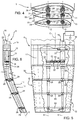
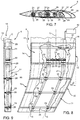
Figure 4 is a view taken from one side of the helicopter and on a still further enlarged scale of the blade inFigure 3 in the first operating condition, with parts removed for clarity; -
Figure 5 is a view taken from above the helicopter of the blade inFigure 4 in the first operating condition; -
Figure 6 is a view taken from the front of the helicopter of the blade inFigures 4 and 5 in the first operating condition; -
Figure 7 is a view taken from one side of the helicopter and on a still further enlarged scale of the blade inFigure 3 in the second operating condition; -
Figure 8 is a view taken from above the helicopter of the blade inFigure 7 in the first operating condition; -
Figure 9 is a view taken from the front of the helicopter of the blade inFigures 7 and 8 in the first operating condition; -
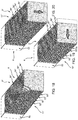
Figure 10 is a perspective view of the blade inFigures 4 to 9 in the first operating condition, with parts removed for clarity; -
Figure 11 is a perspective view of the blade inFigures 4 to 10 in the second operating condition, with parts removed for clarity; -
Figure 12 is a cross-section of the blade inFigures 4 to 11 along line XII-XII inFigure 11 ; -
Figure 13 is a longitudinal section of the blade inFigures 4 to 12 along line XIII-XIII inFigure 11 ; -
Figures 14 and 15 are cross-sections of the blade inFigures 4 to 14 along lines XIV-XIV and XV-XV inFigure 13 , respectively; -
Figure 16 shows a helicopter comprising a rotor according to a second embodiment of the present invention; -
Figure 17 shows a perspective view, on a highly enlarged scale, of a blade of the rotor inFigure 16 , with parts removed for clarity; and -
Figures 18 to 20 schematically show the shape of the blade of a rotor according to a third embodiment of the invention, with parts removed for clarity; -
Figure 21 shows, in a first configuration, a blade of a rotor according to a fourth embodiment, which is not part of the present invention and is shown only for illustrative purposes; -
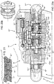
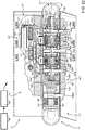
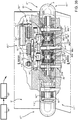
Figures 22 and23a are partially sectioned views of the blade ofFigures 21 in a first position and in a second position respectively, in enlarged view and parts removed for clarity; -
Figure 23b is an enlarged view of some components ofFigure 23a ; -
Figures 24 to 26 are sections taken along respective lines XXIV-XXIV and XXV-XXV and XXVI-XXVI ofFigure 22 ; -
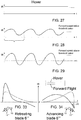
Figures 27 to 29 show the temporal variation of the lift acting on the tip portions of the blade ofFigures 21 to 23a , when the helicopter is respectively in hover, in forward flight at a speed below a threshold value and at a speed above the threshold value; -
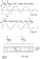
Figure 30 shows the aerodynamic moment acting on the tip of the blade ofFigures 21 to 23a during the transition from the first position to the second position in the condition ofFigure 27 ; -
Figure 31 shows the aerodynamic moment acting on the tip of the blade ofFigures 21 to 23a during the transition from the second position to the first position in the condition ofFigure 27 ; -
Figure 32 shows the movement of the tip between the first and the second position as a function of the forward speed of the helicopter; -
Figures 33 and 34 show the lift distribution along the span of the blade ofFigures 21 to 23a in a solid line with reference to a forward flight and in dotted line with reference to an hovering condition, respectively for a retreating blade and an advancing blade; -
Figure 35 shows the forces acting on the tip portion of the blade ofFigures 21 to 23a together with further components of this blade; -
Figure 36 is a partially sectioned view, in a first position, of a blade of a rotor according to a fifth embodiment, which is not part of the present invention and is shown only for illustrative purposes; -
Figure 37 is a perspective view of a tip portion of the blade ofFigure 36 , with parts removed for clarity and in an enlarged view; and -
Figure 38 is a section taken along lines XXXVIII-XXXVIII ofFigure 36 . - Referring to
Figures 1 and 2 ,reference numeral 1 indicates a helicopter. Thehelicopter 1 basically comprises afuselage 2, amain rotor 3 rotating about an axis and atail rotor 4 located at one end of thefuselage 2 and rotating about its own axis transversal to axis A. In particular, theanti-torque tail rotor 4 projects in a cantilever manner from a fin situated at a tail end of thefuselage 2 and is designed to counter the torque transmitted by therotor 3 to thefuselage 2. - In greater detail, the
rotor 3 basically comprises: - a
mast 5 rotating about an axis A transversal to the axis of rotation of the main rotor; - a plurality of
blades 6, five in the case shown, extending along respective directions substantially radial to axis A; and - a
hub 7 operatively connected to themast 5 and from which theblades 6 extend in a cantilever manner. - In greater detail, the
hub 7 drives theblades 6 in rotation about axis A and enables theblades 6 to rotate, under the action of an external drive, about respective directions of extension to vary the respective angles of attack with respect to the airflow. - The
blades 6 are hinged to thehub 7 so as to be movable about different axes, according to the configuration of therotor 3. - In the following description, reference will be made to only one
blade 6, as theblades 6 are all identical. - The
blade 6 comprises: - a
main portion 10 defining a root of theblade 6 hinged to thehub 7 and extending along an axis C (Figures 3 to 8 ) transversal to axis A; and - a
tip portion 11 arranged at the far end of themain portion 10 with respect to thetip portion 11. - The
main portion 10 is longer than thetip portion 11 in the direction of radial extension of theblade 6. - The
tip portion 11 is movable with respect to themain portion 10.
Thetip portion 11 is selectively movable with respect to themain portion 10 between: - a first position (assumed by the blades indicated with a continuous line in
Figure 1 and byreference numeral 6b inFigure 2 ), in which it defines a dihedral or anhedral angle α with respect to themain portion 10; and - a second position (assumed by the blades indicated by with a dotted line in
Figure 1 and byreference numeral 6a inFigure 2 ), in which it defines a positive or negative sweep angle β with respect to themain portion 10. - The
main portion 10 andtip portion 11 have respective leading 12 and 13 and trailingedges - The term dihedral/anhedral angle α indicates the angle formed between the
leading edge 13 of thetip portion 11 and the leadingedge 12 of themain portion 10 on a plane parallel to axis A and to axis C, at the common point of theleading edges - An anhedral angle α indicates that the leading
edge 13 of thetip portion 11 is inclined towards thefuselage 2 with respect to the leadingedge 12 of themain portion 10. - Whereas a dihedral angle α indicates that the leading
edge 13 of thetip portion 11 is inclined away fromfuselage 2 with respect to the leadingedge 12 of themain portion 10. - The term sweep angle β indicates the angle formed between the
leading edge 13 of thetip portion 11 and the leadingedge 12 of themain portion 10 in a plane transversal to axis A, at the common point of theleading edges - A positive sweep angle β indicates that the leading
edge 13 of thetip portion 11 is arranged downstream with respect to the leadingedge 12 of themain portion 10, with reference to the direction of motion of theblade 6 about axis A. - Whereas a negative sweep angle β indicates that the leading
edge 13 of thetip portion 11 is arranged upstream with respect to the leadingedge 12 of themain portion 10, with reference to the direction of motion of theblade 6 about axis A. - More specifically, the sweep angle β of the
tip portion 11 with respect to themain portion 10 is minimized when thetip portion 11 is arranged in the first position. - The dihedral angle α of the
tip portion 11 with respect to themain portion 10 is zero, when thetip portion 11 is arranged in the second position. - The
blade 6 also comprises anactuator unit 16 to produce the transition of thetip portion 11 between the first and second positions. - In greater detail, the
actuator unit 16 comprises (Figures 3 to 9 ) : - a
motor 20; - a plurality of
rods 21 operatively connected to consecutive sections of thetip portion 11 and destined to induce the transition of thetip portion 11 between the first and second positions; and - a
transmission unit 22 functionally interposed between themotor 20 and therods 21. - In the case shown, the
motor 20 is a stepper motor. - Furthermore, the
motor 20 is housed inside themain portion 10. - The
rods 21 rotate about respective axes parallel to each other and to axis C, and in turn comprise: -
sections 25 housed in themain portion 10 and extending parallel to the associated axis C; and -
sections 26 housed in thetip portion 11 and extending along respective axes D with respect to axis C. - In particular,
sections 26 are inclined with respect tosections 25. - In the case shown,
sections 25 and the associated axes C are straight, whilesections 26 and the associated axes D are curved. - In the case shown,
sections 26 are shaped in such a way that: - the axes D extend, with respect to axis C, towards the
fuselage 2 when theblade 6 is arranged in the first position (Figures 4 to 6 ) ; - the axes extend, with respect to axis C, in the opposite direction to that of the motion of the
blade 6 when the latter is arranged in the second position (Figures 7 to 9 ). -
Sections 26 are housed in a rotatable manner insiderespective apertures 27 defined byribs 28 of thetip portion 11. - In this way, the
rods 21 are rotatable with respect to theribs 28. - Preferably, the
rods 21 are connected to therespective ribs 28 by corresponding articulated joints 29 (Figures 4-9 ). - Furthermore, the
rods 21 are axially constrained to theribs 28 parallel to axis C in a manner not shown in detail in the accompanying figures. - Thanks to the mode of constraint between the
rods 21 and theribs 28, the latter move in a plane orthogonal to axis C and their section in this plane does not change during the transition of thetip portion 11 between the corresponding first and second positions, so as not to alter the sections transversal to axis D of thetip portion 11. Whereas the sections of thetip portion 11 interposed between theribs 28 elastically shear deform in a plane orthogonal to thetip portion 11. - The
ribs 28 are spaced apart along the direction of extension of thetip portion 11. - More specifically, the section area of the
rods 21 transversal to associated axis D decreases when proceeding along thetip portion 11 away from axis A. - The
rods 21 also perform the function of supporting the bending moments and shear loads on the associatedblades 6. In other words, therods 21 perform the structural function normally carried out by the spars used in the blades. - In the case shown in
Figure 13 , therods 21 have a circular section in a plane orthogonal to axes C and D. The diameter of therods 21 decreases when proceeding along thetip portion 11 following axes D. - In the case shown, there are five rods 21 (only some of which are shown in
Figures 3 to 9 ). - The
transmission unit 22 comprises, in particular, (Figures 3 to 9 ) : - a
cogwheel 30 connected to anoutput shaft 31 of themotor 20; - a plurality of
cogwheels 32 connected torespective rods 21; and - a plurality of
cogwheels 33 interposed betweencogwheel 30 andcogwheels 32. - The
helicopter 1 also comprises a control unit 40 (only shown schematically inFigure 3 ) configured to: - arrange the
blades 6 in the respective first positions, when thehelicopter 1 is in the hovering condition; and - arrange the
blades 6 in the respective second positions, when thehelicopter 1 is in the forward flight condition. - The
tip portion 11 comprises a covering 50 defining the aerodynamic surface. - The operation of the
rotor 3 will now be described in detail below. - In particular, the operation of the
rotor 3 is described with reference to asingle blade 6, the operation of all theblades 6 being identical. - In the case where it is necessary to maintain the
helicopter 1 in hovering conditions, thecontrol unit 40 controls themotor 20 so as to arrange thetip portion 11 in the first position (Figures 4 to 6 ), where angle α is anhedral and the sweep angle β is minimized. - In the case where it is required to fly forwards with the
helicopter 1, thecontrol unit 40 controls themotor 20 so as to arrange thetip portion 11 in the second position (Figures 7 to 9 ), where the dihedral angle α is zero and the sweep angle β is positive. - The operation of the
rotor 3 during the transition of theblade 6 from the first position to the second position will now be described. - The
motor 20, via thetransmission unit 22, causes the rotation of therods 21 about axis C, by an angle of ninety degrees in the case shown. - This causes a ninety-degree rotation with a circumferential arc trajectory of
sections 26 of therods 21 about axis C. - Since
sections 26 of therods 21 are inclined with respect to the associatedsections 25 and can rotate inside theapertures 27 of theribs 28, thetip portion 11 deforms. - In particular, the
ribs 28 of thetip portion 11 move rigidly, maintaining their shape in planes orthogonal to the axes D as they are in contact with therods 21, while the sections of thetip portion 11 interposed between theribs 28 elastically shear deform. - Referring to
Figures 16 and17 , reference numeral 3' indicates, as a whole, a rotor according to a second embodiment of the present invention. - Rotor 3' differs from
rotor 3 in that it comprises a pair of freewheels 51' interposed along one of the actuating rods 21' and configured to prevent rotation of the rods 21' about axis C in the clockwise and anticlockwise directions, respectively. In particular, it is possible to selectively activate one of the freewheels 51' and deactivate the other freewheel 51'. - The operation of rotor 3' differs from
rotor 3 in that it uses, at least in forward flight at speeds above a threshold value, the aerodynamic force acting on thetip portions 11 to move them between the first and second operating positions. - In fact, at speeds above the threshold value, the lift acting on the
tip portions 11 varies in sign depending on whether the associatedblades 6 are advancing or retroceding. - Referring to
Figure 16 , lift is directed downwards when theblades 6 are advancing - i.e. they have respective tangential velocities concordant with the direction of flight of the helicopter 1 - and upwards when theblades 6 are retroceding - i.e. they have respective tangential velocities discordant with respect to the direction of flight of thehelicopter 1. - Rotor 3' uses, jointly with the
motor 20, the downward (upward) lift forces to arrange thetip portions 11 in the first position with an anhedral (dihedral) angle a, before setting thehelicopter 1 in hovering conditions. - In particular, when it is necessary to arrange the tip portion with a dihedral (anhedral) angle a, the freewheel 51' that allows rotation in the clockwise (anticlockwise) direction of the rods 21' is activated and the other freewheel 51' is deactivated (and vice versa).
- The covering 50 also comprises (
Figure 17 ) fibres arranged along the associated axes D so that it becomes axially rigid and shear-flexible. - Referring to
Figures 18 to 20 ,reference numeral 3" indicates, as a whole, a rotor according to a third embodiment of the present invention. -
Rotor 3" differs fromrotor 3 in that thetip portion 11" of each blade 6 (shown entirely schematically) is formed by a plurality ofelements 55" in a rigid material and elements in aviscoelastic material 56" lying on respective planes orthogonal to axis C and alternating with one another along axis C. - In this way, the
tip portions 11 are particularly rigid to flexure in planes orthogonal to axis C so as to maintain the shape of theribs 28 and therefore the aerodynamic efficiency of the covering 50, and shear deformable in planes perpendicular to axis C under the action of therods 21. - The operation of
rotor 3" is identical to that ofrotor 3 and is therefore not described in detail. - Referring to
Figures 21 to 35 , reference numeral 3''' indicates, as a whole, a rotor according to a fourth embodiment, which is not part of the present invention and is shown only for illustrative purposes. - Rotor 3''' differs from
rotor 3 in that it does not comprise actuatingunit 16 and in that the adjustment of the position of tip portions 11''' relative tomain portion 10 is achieved by means of the resultant moments Mr generated by inertia forces and aerodynamic forces and/or elastic forces and/or damping forces on respective tip portions 11'''. - Furthermore, differently from
blade 6 ofrotor - In particular, tip portion 11''' of each blade 6''' is movable with respect to relative
main portion 10 between: - a relative first angular position, in which it defines anhedral angle α with respect to relative
main portion 10; and - a relative second angular position, in which it defines a null angle or a minimized anhedral angle α with respect to relative
main portion 10. - In the embodiment shown, when set in the first angular position, tip portion 11''' is arranged at a lower level than in the second angular position.
- Blade 6''' comprises connecting means 60''' for connecting tip portion 11''' to
main portion 10 movably between the first and second position. - In greater detail, connecting means 60''' comprises a hinge 61''' extending about an axis F tangential to axis A and about which tip portion 11''' is hinged to
main portion 10. - Still more precisely, hinge 61''' comprises (
Figure 22 ): - a tubular element 105''' coaxial to axis F;
- a number of protrusion 106''', 107''', protruding from
main portion 10 and axially spaced along axis F, and angularly and axially connected to tubular element 105'''; and - a plurality of joining
elements 109b''', three in the embodiment shown, articulated onto tubular element 105''' about axis F and protruding from tip portion 11''' . - Protrusion 106''' comprises a conical end 108''' coaxial to axis C and fitted inside a body 110''' onto which a further joining
element 109a''' is articulated about axis F. Further joiningelement 109a''' also protrudes from tip portion 11''' . - Connecting means 60''' can be selectively set in a first configuration (
Figure 22 ) in which they: - allow the rotation of tip portion 11''' with respect to
main portion 10 in a first angular direction and up to the first angular position; and - prevent the rotation of tip portion 11''' with respect to
main portion 10 in a second angular direction opposite to the first angular direction. - Furthermore, connecting means 60''' can be selectively set in a second configuration (
Figure 23a ), in which they: - allow the rotation of tip portion 11''' with respect to
main portion 10 in the second angular direction and up to the second angular position; and - prevent the rotation of tip portion 11''' with respect to
main portion 10 in the first angular direction. - In the embodiment shown, the first angular direction corresponds to a downwards movement of tip portions 11''' about relative axes C, i.e. to an increase of the anhedral angle α or to a decrease of dihedral angle.
- The second angular direction corresponds to an upwards movement of tip portions 11''', i.e. to a decrease of anhedral angle α or to an increase of dihedral angle.
- Preferably, each tip portion 11''' is set in the respective first angular position, when
helicopter 1 is in hover and is set in the respective second angular position, whenhelicopter 1 is in forward flight. - Furthermore, each tip portion 11''' is movable from the first angular position to the second angular position, when
helicopter 1 is in hover or in forward flight with a speed lower than a threshold value andhelicopter 1 must be arranged in a configuration optimized for forward flight. Accordingly, connecting means 60''' are set in the first configuration, whenhelicopter 1 is in hover or in forward flight with a speed lower than a threshold value, and are moved to the second configuration whenhelicopter 1 must be arranged in a configuration optimized for forward flight. - Each tip portion 11''' is also movable from the second angular position to the first angular position when
helicopter 1 is in forward flight andhelicopter 1 must be arranged in a configuration optimized for hovering. Accordingly, connecting means 60''' are set in the second configuration, whenhelicopter 1 is in forward flight with a speed greater than a threshold value, and are moved to the first configuration, whenhelicopter 1 must be arranged in a configuration optimized for hovering. - In the following of the present description, reference will be made to only one blade 6''', being all blades 6''' identical one another.
- Preferably, blade 6''' comprises (
Figures 22 ,23a and35 ) a rotational spring 90''', which is interposed between relativemain portion 10 and tip portion 11''' and exerts an elastic torque Mk about relative axis F on tip portion 11'''. - In the embodiment shown, spring 90''' elastically pre-loads tip portion 11''' towards the first angular position.
- Preferably, blade 6''' comprises (
Figures 22 ,23a and35 ) a rotational damper 92''', which is interposed betweenmain portion 10 and tip portion 11''', and exerts a damping torque Md dependent on the rate of rotation about axis F on tip portion 11'''. - In the embodiment shown, spring 90''' and/or damper 92''' are housed inside body 110'''
- Preferably, blade 6''' comprises a plurality of ballasts 91''' arranged on tip portion 11''' and aimed to locate the centre of mass of tip portion 11''' as close as possible to axis F, so as to minimize the moment Mc due to centrifugal force and other inertial actions acting on tip portion 11''' (
Figure 35 ) . - Ballasts 91''' are fixed to
main portion 10. In particular, ballasts 91''' are radially opposed radially to axis F with respect to respective joiningelements 109a''', 109b'''. In the embodiment shown, ballasts 91''' are made in tungsten. - With reference to
Figures 27 to 29 , it is shown the temporal variation of the lift acting on tip portion 11''' for three different flight condition ofhelicopter 1. - In the following of the present description, the expression "positive lift" will indicate an upwardly directed lift while the expression "negative lift" will indicate a downward directed lift.
- In particular,
Figure 27 shows the temporal variation of lift resulting on tip portion 11''' of blade 6''' in a hover condition ofhelicopter 1. In this hover condition, the lift is positive and substantially constant in value. Accordingly, the aerodynamic moment Mlift generated on tip portion 11''' by the lift is constant directed in the second angular direction, counter-clockwise inFigure 35 . -
Figure 28 shows the temporal variation of lift resulting on tip portion 11''' of blade 6''' in a forward flight ofhelicopter 1 with a speed below a threshold value. In this condition, the lift is positive but cyclically changes in value. Accordingly, the aerodynamic moment Mlift generated by the lift on tip portion 11''' is variable and directed in the second angular direction, counter-clockwise inFigure 35 . -
Figure 29 is relative to a forward flight condition ofhelicopter 1 with a speed above a threshold value. In this condition, the lift acting on tip portion 11''' is cyclically positive and negative (upwards and downwards directed) and changes in value. In particular (seeFigure 33 and 34 ),: - when blade 6''' is advancing (
Figure 34 ), i.e. is moving towards the front ofhelicopter 1, tip portion 11''' undergoes a negative lift; and - when blade 6''' is retreating (
Figure 33 ), i.e. is moving towards the rear ofhelicopter 1,tip portion 11" undergoes a positive lift. - Accordingly, aerodynamic moment Mlift acting on tip portion 11''' of blade 6''' is directed in the first angular direction, clockwise in
Figure 35 , whenblade 6 is advancing; and is directed in the second angular direction, counter-clockwise inFigure 35 , when blade 6''' is retreating. - Moments Mlift, Mk, Md, Mc generate a resulting moment Mr about axis on tip portions 11'''. Preferably, spring 90''', ballasts 91''' and
damper 92" are configured to direct resulting moment Mr: - in the second angular direction, when
helicopter 1 in in hover or in forward flight with a speed lower than the threshold value; and - cyclically in the first and second angular directions (respectively if the blade is advancing or retreating), when
helicopter 1 is in forward flight with a speed greater than the threshold value. - Depending on the orientation of resulting moment Mr and on the configuration of connecting means 60''', tip portion 11''' is rotated in the first or in the second angular direction or remains angularly fixed with respect to
main portion 10. - In particular, in case resulting moment Mr is directed in the first angular direction and connecting means 60''' are set in the first configuration, tip portion 11''' is rotated up to the first angular position.
- In case resulting moment Mr is directed in the first angular direction and connecting means 60''' are set in the second configuration, tip portion 11''' is not rotated.
- In case resulting moment Mr is directed in the second angular direction and connecting means 60''' are set in the second configuration, tip portion 11''' is rotated up to the second angular position.
- In case resulting moment Mr is directed in the second angular direction and connecting means 60''' are set in the first configuration, tip portion 11''' is not rotated.
- Furthermore, blade 6''' comprises a partially relieved stop element 88''', which defines a first and a second stop for tip portion 11''' set in the first angular position and the second angular position respectively.
- Preferably, stop element 88''' stops tip portion 11''' in the first position at anhedral angle α of about 20 degrees with respect to the plane of
main portion 10 and in the second position at a null anhedral angle α with respect to the plane ofmain portion 10. - In greater detail, blade 6''' comprises an actuator 65''' controllable by a control unit 66''' of rotor 3''' and which can be operated to set connecting means 60''' in either the first configuration or the second configuration.
- In greater detail, actuator 65''' is housed inside
main portion 10. - Actuator 65''' comprises (
Figures 22 and23a ): - an electric motor 70''' controlled by control unit 66''' and having an output shaft 71''' rotating parallel to axis F;
- an output member 73''' slidable parallel to axis F; and
- a transmission group 72''' interposed between electric motor 70''' and output member 73'''.
- In particular, transmission group 72''' comprises:
- a shaft 74''' rotatable parallel to axis F, provided with a worm-screw 75''' and having a gear 76''' at an end thereof;
- a gear 77''' meshing with gear 76''' and arranged at an axial end of output shaft 71'''; and
- a slide 78''', which is free to slide parallel to axis F, comprises a rack 79''' meshing with worm-screw 75''' and is integrally movable together with output member 73'''.
- Output member 73''' is housed in a compartment of
main portion 10. - Connecting means 60''' comprise, in turn,:
- a plurality of coupling elements 80''' carried by
main portion 10 and connected to output member 73'''; and - a plurality of
coupling elements 81a''', 81b''' carried by tip portion 11'''. - In particular,
coupling elements 81a''' are arranged at axial ends of tip portions 11''' with respect to axisF. Coupling elements 81b''' (only one of which is shown inFigures 22 and23a ) are axially interposed betweencoupling elements 81a''' and are spaced along axis F - Coupling element 80''' are also axially spaced along axis F.
- In particular, each coupling element 80''' is axially interposed between one
adjacent coupling element 81a''' and anadjacent coupling element 81b''', or between twoadjacent coupling elements 81b''', or between one anadjacent coupling element 81b''' and other oneadjacent coupling element 81a'''. - Actuator 65''' can be operated to alternatively engage coupling elements 80''' with first
adjacent coupling elements 81a''', 81b''' in the first configuration of connecting means 60''', or to engage coupling elements 80''' with secondadjacent coupling elements 81a''', 81b''' in the second configuration of connecting means 60'''. - Each coupling element 80''' comprises, in turn,
- a pair of
axial end disks 82a''', 82b''' opposite to another and having respectivetoothed surfaces 83a''', 83b'''; and - a pair of one-way freewheel clutches 84''', 85''' axially interposed between
disks 82a''', 82b'''. - In greater detail, surfaces 83a''', 83b''' are arranged on respective opposite axial sides of one-way freewheel clutches 84''', 85'''.
- Furthermore, one-way freewheel clutch 84''' allows the rotation of
disk 82a''' only in the first angular direction and one-way freewheel clutch 85''' allows the rotation ofdisk 82b''' only in the second angular direction. - Each
coupling element 81b''' comprises a pair ofaxial end disks 86a''', 86b''' opposite to another and having respectivetoothed surfaces 87a''', 87b'''. - Each
coupling element 81a''' comprises only oneaxial end disk 86a''' having respectivetoothed surface 87a'''. -
Surfaces 83a''', 83b''' of coupling element 80''' face surfaces 87a''', 87b''' ofcoupling elements 81a''', 81b''', which are axially adjacent thereto. - Actuator 65''' can be operated to displace coupling elements 80''' along axis F:
- either up to a first axial position in which surfaces 83a''' of
disk 82a''' mesh withrespective surfaces 87a''', 87b''' ofdisk 86a''' of firstadjacent coupling elements 81a''', 81b''' so as to determine the engagement of coupling element 80''' and firstadjacent coupling element 81a''', 81b'''; - or up to a second axial position in which surfaces 83a''' of
disk 82a''' mesh withrespective surface 87a'''. 87b''' of secondadjacent coupling elements 81a''', 81b''', so as to determine the engagement of coupling element 80''' and secondadjacent coupling element 81a''', 81b'''. - In the first axial positon, one-way freewheel clutches 84''' allow tip portion 11''' to rotate in the first angular direction relative to
main portion 10 and prevent tip portion 11''' from rotating in the second direction relative tomain portion 10. - In the second axial positon, one-way freewheel clutches 85''' allow tip portion 11''' to rotate in the second angular direction relative to
main portion 10 and prevent tip portion 11''' from rotating in the first direction relative tomain portion 10. - In particular, teeth of
toothed surface 83a''', 83b''' and teeth of toothed surfaces, 87a''', 87b''' are shaped in such a way that whentoothed surfaces 83a''', 83b''' engage respective toothed surfaces, 87a''', 87b''',disks 82a", 86a" and 82b", 86b" can rotate integrally with one another about axis F, in both the first and the second angular directions. - The operation of rotor 3''' differs from that of
rotor 3 in that the angular position of tip portion 11''' with respect tomain portion 10 is determined by the resulting moment Mr on tip portion 11''' and by the position of connecting means 60'''. - The operation of rotor 3''' will be now described starting from a flight condition, in which
helicopter 1 is in hovering and with reference to a single blade 6'''. - In this flight condition, aerodynamic moment Mlift is directed in the second direction when blade 6''' is advancing or retroceding.
- Furthermore, control unit 66''' sets actuator 65''' in the first axial position. Accordingly, connecting means 60''' are set in the first configuration (shown in
Figure 22 ), in which they prevent the rotation of tip portion 11''' in the second angular direction with respect tomain portion 10 and only allow the rotation of tip portion 11''' in the first angular direction with respect tomain portion 10. - Accordingly, tip portion 11''' is kept in the first angular position in which it defines anhedral angle α with respect to
main portion 10. - Furthermore, tip portion 11''' abuts against stop element 88''', which prevents any further rotation thereof in the first angular direction and any consequent undesired increase of anhedral angle α.
- Being connecting means 60''' set in the first configuration, coupling elements 80''' engage
coupling elements 81a'''. Still more precisely, surfaces 83b''' ofdisks 82b''' engagesurfaces 87a''', 87b''' ofdisk 86a''', 86b''' of first adjacent connectingelement 81a''', 81b'''. Furthermore, one-way freewheel clutch 84''' allows tip portion 11''' to rotate in the first angular direction relative tomain portion 10 and prevents tip portion 11''' from rotating in the second angular direction. - In case it is necessary to operate
helicopter 1 in forward flight, control unit 66''' sets actuator 65''' in the second axial position. As a consequence, connecting means 60''' are also set in the second configuration (Figure 23a ), in which they allow the rotation of tip portion 11''' with respect tomain portion 10 in the second angular direction and prevent the rotation of tip portion 11''' in the first angular direction. - Thanks to the fact that connecting means 60''' are now set in the second configuration, tip portion 11''' increasingly rotates in the second angular direction only, up to when it reaches the second angular position in which the anhedral angle α is substantially null. In the second angular position, tip portion 11''' abuts against stop element 88''' which prevents any further rotation thereof in the second angular direction and any consequent undesired increase of the dihedral angle.
- In particular, being connecting means 60''' set in the second configuration, control unit 66''' sets actuator 65''' in the second axial position (
Figure 23a ).
Therefore, coupling elements 80''' engage secondadjacent coupling elements 81a''', 81b'''. Still more precisely, surfaces 83a''' ofdisks 82a''' engagesurfaces 87a''', 87b''' ofdisk 86a''', 86b''' of secondadjacent coupling elements 81a''', 81b'''. Furthermore, one-way freewheel clutches 85''' allow tip portion 11''' to rotate in the second direction relative tomain portion 10 and prevent tip portion 11''' from rotating in the first direction. - In case it is necessary to operate
helicopter 1 in hovering, control unit 66''' sets back actuator 65''' in the first axial position. As a consequence, connecting means 60''' are also set in the first configuration (Figure 23a ), in which they allow the rotation of tip portion 11''' with respect tomain portion 10 in the first angular direction only and prevent the rotation of tip portion 11''' in the second angular direction. - The increase in the forward speed of
helicopter 1 causes at a speed greater than the threshold value: - a positive lift acting on tip portion 10''' of blade 6''' both when it advances and retrocedes when the forward speed of
helicopter 1 is still lower than the threshold value; and - a positive lift acting on tip portion 10''' of blade 6''' when it retrocedes and a negative lift acting on tip portion 10''' of blade 6''' when it advances, when the forward speed of
helicopter 1 is greater than the threshold value. - Accordingly, when the
helicopter 1 still is in forward flight with a speed greater than the threshold value, tip portion 11''' rotates back in the first angular direction up to when it reaches the first position. This is due to the fact that, being negative the lift on tip portion 11''' of advancing blade 6''', resulting moment Mr on tip portion 11''' is directed in the first direction when blade 6''' is advancing. - At this point,
helicopter 1 is set in hovering. - Referring to
Figures 36 to 38 , reference numeral 3'''' indicates, as a whole, a rotor according to a fifth embodiment, which is not part of the present invention and is shown only for illustrative purposes. - Rotor 3'''' differs from rotor 3''' in that each coupling element 80'''' comprises, in turn,:
- an annular frame 95'''' connected to slide 78''' and movable parallel to axis F with slide 78'''';
- a pair of
axial end disks 82a'''', 82b'''' (86a'''', 86b'''') opposite to another and having respectivetoothed surfaces 83a"", 83b'''' (87a''', 87b'''); - a shaft 99'''' coaxial to axis F; and
- a pair of elements 96'''' arranged at respective axial ends of shaft 99'''' and fixed to
respective disks 82a'''', 82b'''' (86a''', 86b'''). - In greater detail, teeth of
toothed surface 83a'''', 83b'''' and teeth oftoothed surfaces 87a'''', 87b'''' are shaped in such a way that whentoothed surfaces 83a'''', (83b'''') engage respectivetoothed surface 87a'''' (87b'''') of first (second) adjacentangular coupling element 81a'''', 81b'''', the rotation ofdisk 86a'''' (86b'''') in the first (second) angular direction causes the intermittent meshing oftoothed surfaces 87a'''', 87b"". - In particular, the intermittent meshing causes a back and forth movement of
surfaces 83a'''' (83b'''') towards and away fromsurface 87a'''' (87b'''') parallel to axis F. - Furthermore, teeth of
toothed surface 83a'''', 83b'''' and teeth oftoothed surfaces 87a'''', 87b'''' are shaped in such a way that whentoothed surfaces 83a'''', (83b'''') engage respectivetoothed surface 87a'''' (87b''''), the rotation ofdisk 86a'''' (86b'''') in the second (first) angular direction is prevented. - In the embodiment shown, elements 96'''' are angularly movable integrally with shaft 99'''' about axis F and are axially slidable relative to shaft 99'''' along axis F.
- In the embodiment shown, teeth of
surfaces 83a'''', 83b'''' and 87a'''', 87b'''' are saw-teeth shaped. - In the embodiment shown, elements 96'''' are splined on the respective sides facing axis F while shaft 99'''' is splined on the opposite side with respect to axis F.
- Furthermore, each coupling element 80'''' comprises, in turn, elastic means 100'''' interposed between frame 95'''' and elements 96''''. Elastic means 100'''' elastically load elements 96'''' and
disks 82a'''', 82b'''' towardsadjacent disks 86a'''', 86b'''' ofadjacent coupling element 81a'''', 81b''''. - In detail, elastic means 100'''' comprises a plurality of springs 101'''', helical springs in the embodiment shown, interposed between frame 95'''' and elements 96''''.
- Springs 101'''' extend along respective axes parallel to axis F and angularly spaced about axis F.
- The operation of rotor 3'''' differs from that of rotor 3''' in that the, when connecting means 60'''' are set in the first configuration (
Figure 36 ),toothed surfaces 83a'''' ofdisks 82a'''' mesh withtoothed surfaces 87a'''' ofdisks 86a'''' whiletoothed surfaces 83b'''' ofdisks 82b'''' are axially spaced fromtoothed surfaces 87b'''' ofdisks 86b''''. - Due to the shape of teeth of
surfaces 83a'''', 87a'''', the meshing betweendisks 82a'''', 86a'''' allows the intermittent angular rotation ofdisks 86a'''' and, therefore, of tip portion 11'''' in the first angular direction with respect todisks 82a'''' and, therefore, tomain portion 10. - This intermittent angular rotation is formed by a succession of alternate first time intervals in which teeth of
surfaces 83a'''', 87a'''' mesh with one another and second time intervals in which teeth ofsurfaces 83a'''', 87a'''' are disengaged. - During the first time intervals, surfaces 83a'''' rotate in the first angular direction, thus rotating tip portions 11''''.
- During the second time intervals, surfaces 83a'''' do not rotate, and the axial disengaging movement of
surface 82a'''' causes the axial movement of elements 96'''' away fromsurfaces 83a'''' and the compression of springs 101''''. The subsequent extension of spring 101'''' causes the meshing of teeth ofsurfaces 83a'''', 87a'''' ofrespective disks 82a'''', 86a''''. - When the connecting means 60'''' are set in the second angular position, teeth of
surfaces 83b'''', 87b'''' mesh with one another, thus preventing the rotation ofdisks 86b''' and, therefore, oftip portion 11 in the first angular direction and allowing the intermittent angular rotation ofdisks 86b''' and, therefore, oftip portion 11 in the second angular position. - From examination of the characteristics of the
rotor - In particular, the
tip portion 11 of eachblade 6 is selectively movable between: - the respective first position, in which the dihedral/anhedral angle α with respect to the
main portion 10 is non-zero (Figures 4 to 6 ); and - the respective second position, in which the sweep angle β with respect to the
main portion 10 is non-zero (Figures 7 to 9 ) . - In this way, unlike the known types of rotors described in the introductory part of this description, the
rotor - having high aerodynamic efficiency when the
helicopter 1 is in hovering conditions and theblades 6 are arranged in the associated first positions; and - having low noise when the
helicopter 1 is in forward flight conditions and theblades 6 are arranged in the associated second positions. - This behaviour, optimized both in hovering conditions and in forward flight conditions, is obtained in a particularly simple manner and with substantially zero displacement of the barycentre of the
blades 6 along axes C and D between the respective first and second positions. - In this way, the
motor 20 does not need to counter high loads due to centrifugal force and only needs to generate relatively low actuating forces. In consequence, themotor 20 can be compact and low-cost. - Due to the fact that the transition of the
tip portions 11 and 11'' does not result in a substantial variation in the position of the barycentre of the associatedblades 6 along axes C and D, the erroneous operation of one or more of themotors 20 and therefore the erroneous positioning of therespective tip portion 11 and 11'' does not cause inertial unbalancing of therotor - Due to the fact that the
motor 20 is housed in themain portion 10 and that thesections rods 21 are housed in thetip portions 11, therotor blades 6 and does not penalize the overall aerodynamic efficiency of thehelicopter 1. - Finally, it is also clear that modifications and variants can be made regarding the
rotor - In particular, the
rotor helicopter 1. - Furthermore, the
tip portions 11 and 11'' could have dihedral angles α in the respective first positions and negative sweep angles β in the respective second positions.
Thetransmission unit 22 could comprise an epicyclical train interposed between themotor 20 and therods 21. - The
actuator units 16 could be completely housed inside thetip portions 11 of therespective blades 6. - Rotor 3' might not comprise the
transmission unit 22 and could comprise a plurality ofmotors 20 connected to associatedrods 21 and not comprise thetransmission unit 22.
Claims (11)
- A rotor (3, 3', 3") for a hover-capable aircraft (1), comprising:- a hub (7) rotatable about a first axis (A); and- at least two blades (6) hinged to said hub (7);
each of said blade (6) comprising a main portion (10) hinged to said hub (7) and a tip portion (11, 11"), which is arranged radially outermost from said first axis (A) with respect to the corresponding main portion (10);
said tip portion (11, 11") of each of said blade (6) being movable with respect to the corresponding said main portion (10) of that blade (6) between:- a first position, in which it defines a dihedral or anhedral angle (α) with respect to the corresponding said main portion (10); and- a second position, in which it defines a positive or negative sweep angle (β) with respect to the corresponding said main portion (10);each of said blade (6) comprising at least two actuating rods (21), which are operatively connected to the respective said tip portion (11, 11") to cause its transition with respect to the corresponding main portion (10);
each of said actuating rod (21) being rotatable about said second axis (C);
characterized in that each of said actuating rod (21) is curved, at least in part, with respect to said second axis (C) ;
said tip portion (11, 11") comprising at least one rib (28) lying on a plane transversal to said second axis (C) and defining a pair of apertures (27), which are engaged in a freely rotatable manner about said second axis (C) by said respective actuating rods (21);
said ribs (28) maintaining, in use, the respective sections undeformed on planes transversal to said actuating rods (21) during the transition between said first and second positions; the sections of said tip portion (11, 11") interposed between said ribs shear deforming, in use, transversely to said tip portion (11, 11") during the transition between said first and second positions. - A rotor according to claim 1, characterized in that:- said sweep angle (β) with respect to the corresponding said main portion (10) is minimized when each said tip portion (11, 11") is arranged in said first position; and/or- said dihedral angle (α) with respect to the corresponding said main portion (10) is zero when each said tip portion (11, 11") is arranged in said second position.
- A rotor according to claim 1 or 2, characterized in that said main portion (10) of each of said blade (6) extends along a second axis (C) transversal to said first axis (A); said tip portion (11, 11") being movable on a plane transversal to said second axis (C) between said first and second positions.
- A rotor according to any one of claims 24 to 26, characterized in that each of said actuating rod (21) comprises:- a first section (25) housed inside said main portion (10) of the relevant said blade (6) and parallel to said second axis (C); and- a second section (26) housed inside said tip portion (11) of the relevant said blade (6) and inclined with respect to said second axis (C).
- A rotor according to any one of the foregoing claims,
characterized in that the area of each of said actuating rod (21) measured in cross-section transversal to a direction of extension of the actuating rod (21) progressively decreases inside said main portion (10), when proceeding in a direction away from said first axis (A);
and/or characterized in that said actuating rods (21) perform a structural function of supporting bending and shearing loads acting on said blade (6). - A rotor according to any of the foregoing claims,
characterized in that said actuator (16) comprises a motor (20) housed inside said main portion (10) of each blade (6), and in that it comprises a transmission unit (12) to transmit motion from said motor (20) to said actuating rods (21). - A rotor according to claim 6, characterized in that it comprises at least two selectively operable freewheels (51') operatively connected to said rod (21);
said freewheels (51') enabling the rotation of said rods (21) in respective mutually opposite directions, following the aerodynamic action acting on the respective said blade (6). - A hover-capable aircraft, comprising:- a main rotor (3, 3', 3") according to any of the preceding claims; and- a control unit (40) programmed to arrange said tip portions (11, 11") of said blades (6) in the respective said first positions when said aircraft (1) is in hovering conditions and in the respective said second positions when said aircraft (1) is in forward flight conditions.
- A method of controlling a rotor (3, 3, 3") for a hover-capable aircraft (1), said rotor (3, 3, 3") comprising:- a hub (7) rotatable about a first axis (A); and- at least two blades (6) hinged to said hub (7);each of said blade (6) comprising a main portion (10) hinged to said hub (7) and a tip portion (11, 11"), which is arranged radially outermost with respect to said first axis (A) with respect to the corresponding main portion (10);
said method comprising the steps of:i) arranging said tip portions of said blades (6) in respective first positions in which they define respective dihedral or anhedral angles (α) with respect to the associated main portions (10), when said aircraft (1) is in hovering conditions;ii) arranging said tip portions (11, 11") of said blades (6) in respective second positions in which they define positive or negative sweep angles (β) with respect to the associated main portions (10), when said aircraft (1) is in forward flight conditions;characterized by comprising the steps of:iii) housing at least one pair of actuating rods (21) in a rotationally free manner inside respective through apertures (27) in the ribs (28) of said tip portion (11, 11");iv) rotating said actuating rods (21) about a second axis (C) transversal to said first axis (A) to move the associated tip portions (11, 11") between the corresponding first and second positions;v) maintaining the sections of said ribs (28) undeformed in respective planes transversal to said actuating rods (21) during the transition between said first and second positions;vi) shear deforming the sections of said tip portions (11) interposed between said ribs (28);said actuating rods (21) comprising respective first sections (25) and second sections (26) inclined with respect to the corresponding first sections (25);
said second sections (26) being housed inside said apertures (27) in a rotationally free manner with respect to said ribs (28) ; and
said ribs (28) lying on respective planes transversal to said second axis (C). - A method according to claim 9, characterized in that:- said sweep angles (β) of each said tip portion (11, 11") with respect to the corresponding said main portion (10) are minimized when each said tip portion (11, 11") is arranged in said first position; and/or- said dihedral angles (α) of each tip portion (11, 11") with respect to the corresponding said main portion (10) are zero when each said tip portion (11, 11") is arranged in said second position.
- A method according to claim 9 or 10, characterized in that it comprises the step vii) of operating said actuating rods (21) by means of a dedicated actuator (16) or by means of the aerodynamic action acting on said tip portions (21) during the rotation of said rotor (3'); and/or
characterized in that it comprises the step viii) of rotating said tip portions (11, 11") about said second axis (C).
Applications Claiming Priority (3)
| Application Number | Priority Date | Filing Date | Title |
|---|---|---|---|
| EP16187546.3A EP3293112B1 (en) | 2016-09-07 | 2016-09-07 | Rotor for a hover-capable aircraft and related method of control |
| EP17761295.9A EP3509946B1 (en) | 2016-09-07 | 2017-09-07 | Rotor for a hover-capable aircraft and related method of control |
| PCT/EP2017/072496 WO2018046612A1 (en) | 2016-09-07 | 2017-09-07 | Rotor for a hover-capable aircraft and related method of control |
Related Parent Applications (2)
| Application Number | Title | Priority Date | Filing Date |
|---|---|---|---|
| EP17761295.9A Division EP3509946B1 (en) | 2016-09-07 | 2017-09-07 | Rotor for a hover-capable aircraft and related method of control |
| EP17761295.9A Division-Into EP3509946B1 (en) | 2016-09-07 | 2017-09-07 | Rotor for a hover-capable aircraft and related method of control |
Publications (2)
| Publication Number | Publication Date |
|---|---|
| EP3536611A1 true EP3536611A1 (en) | 2019-09-11 |
| EP3536611B1 EP3536611B1 (en) | 2020-11-04 |
Family
ID=56896386
Family Applications (4)
| Application Number | Title | Priority Date | Filing Date |
|---|---|---|---|
| EP16187546.3A Active EP3293112B1 (en) | 2016-09-07 | 2016-09-07 | Rotor for a hover-capable aircraft and related method of control |
| EP17168851.8A Active EP3293113B1 (en) | 2016-09-07 | 2016-09-07 | Rotor for a hover-capable aircraft and related method of control |
| EP19171701.6A Active EP3536611B1 (en) | 2016-09-07 | 2017-09-07 | Rotor for a hover-capable aircraft and related method of control |
| EP17761295.9A Active EP3509946B1 (en) | 2016-09-07 | 2017-09-07 | Rotor for a hover-capable aircraft and related method of control |
Family Applications Before (2)
| Application Number | Title | Priority Date | Filing Date |
|---|---|---|---|
| EP16187546.3A Active EP3293112B1 (en) | 2016-09-07 | 2016-09-07 | Rotor for a hover-capable aircraft and related method of control |
| EP17168851.8A Active EP3293113B1 (en) | 2016-09-07 | 2016-09-07 | Rotor for a hover-capable aircraft and related method of control |
Family Applications After (1)
| Application Number | Title | Priority Date | Filing Date |
|---|---|---|---|
| EP17761295.9A Active EP3509946B1 (en) | 2016-09-07 | 2017-09-07 | Rotor for a hover-capable aircraft and related method of control |
Country Status (6)
| Country | Link |
|---|---|
| US (3) | US11014660B2 (en) |
| EP (4) | EP3293112B1 (en) |
| KR (1) | KR102276875B1 (en) |
| CN (1) | CN109789924B (en) |
| RU (1) | RU2730786C1 (en) |
| WO (1) | WO2018046612A1 (en) |
Families Citing this family (4)
| Publication number | Priority date | Publication date | Assignee | Title |
|---|---|---|---|---|
| EP3293112B1 (en) * | 2016-09-07 | 2018-12-05 | Leonardo S.p.A. | Rotor for a hover-capable aircraft and related method of control |
| US10787251B2 (en) | 2017-03-07 | 2020-09-29 | Textron Innovations Inc. | Variable sweep rotorcraft blade tip |
| WO2026036252A1 (en) * | 2024-08-12 | 2026-02-19 | 深圳市大疆创新科技有限公司 | Aircraft, blade, propeller, propulsion assembly, and movable platform |
| CN120364130B (en) * | 2025-06-26 | 2025-10-14 | 中国东方航空设备集成有限公司 | A variable-sweep rotor |
Citations (5)
| Publication number | Priority date | Publication date | Assignee | Title |
|---|---|---|---|---|
| EP1127786A1 (en) | 2000-02-23 | 2001-08-29 | Fuji Jukogyo Kabushiki Kaisha | Rotary blade of helicopter |
| US20060027703A1 (en) | 2004-07-23 | 2006-02-09 | Richard Bussom | System and method for improved rotor tip performance |
| EP2228299A2 (en) | 2009-03-13 | 2010-09-15 | EADS Deutschland GmbH | Anisotropic actuation of a helicopter rotor blade tip |
| KR20120059091A (en) | 2010-11-30 | 2012-06-08 | 부산대학교 산학협력단 | Aircraft Wing with punched tip |
| US20160075430A1 (en) | 2014-09-15 | 2016-03-17 | Bell Helicopter Textron Inc. | Variable anhedral tip rotor blade |
Family Cites Families (7)
| Publication number | Priority date | Publication date | Assignee | Title |
|---|---|---|---|---|
| US4324530A (en) * | 1980-01-21 | 1982-04-13 | United Technologies Corp. | Helicopter blade with a tip having a selected combination of sweep, taper and anhedral to improve hover efficiency |
| DE3242584A1 (en) * | 1982-11-18 | 1984-05-24 | Messerschmitt-Bölkow-Blohm GmbH, 8000 München | ARRANGEMENT OF ADDITIONAL SURFACES AT THE TIPS OF AN WING |
| FR2755941B1 (en) * | 1996-11-19 | 1999-01-15 | Eurocopter France | ARROW BLADE AT ARROW FOR AIRCRAFT TURNING WING |
| DE19926832B4 (en) * | 1999-06-12 | 2005-09-15 | Airbus Deutschland Gmbh | Subsonic aircraft preferably with swept-up wings |
| US7513750B2 (en) * | 2006-03-08 | 2009-04-07 | Sikorsky Aircraft Corporation | Rotor blade tip planform |
| RU2546337C1 (en) * | 2014-02-04 | 2015-04-10 | Сергей Нестерович Белоглазов | Fixed or controlled propeller blade tip (winglet) |
| EP3293112B1 (en) * | 2016-09-07 | 2018-12-05 | Leonardo S.p.A. | Rotor for a hover-capable aircraft and related method of control |
-
2016
- 2016-09-07 EP EP16187546.3A patent/EP3293112B1/en active Active
- 2016-09-07 EP EP17168851.8A patent/EP3293113B1/en active Active
-
2017
- 2017-09-07 RU RU2019110129A patent/RU2730786C1/en active
- 2017-09-07 CN CN201780055079.XA patent/CN109789924B/en active Active
- 2017-09-07 US US16/328,069 patent/US11014660B2/en active Active
- 2017-09-07 WO PCT/EP2017/072496 patent/WO2018046612A1/en not_active Ceased
- 2017-09-07 EP EP19171701.6A patent/EP3536611B1/en active Active
- 2017-09-07 KR KR1020197009223A patent/KR102276875B1/en active Active
- 2017-09-07 EP EP17761295.9A patent/EP3509946B1/en active Active
-
2021
- 2021-04-22 US US17/237,813 patent/US11623744B2/en active Active
- 2021-04-22 US US17/237,520 patent/US11618558B2/en active Active
Patent Citations (5)
| Publication number | Priority date | Publication date | Assignee | Title |
|---|---|---|---|---|
| EP1127786A1 (en) | 2000-02-23 | 2001-08-29 | Fuji Jukogyo Kabushiki Kaisha | Rotary blade of helicopter |
| US20060027703A1 (en) | 2004-07-23 | 2006-02-09 | Richard Bussom | System and method for improved rotor tip performance |
| EP2228299A2 (en) | 2009-03-13 | 2010-09-15 | EADS Deutschland GmbH | Anisotropic actuation of a helicopter rotor blade tip |
| KR20120059091A (en) | 2010-11-30 | 2012-06-08 | 부산대학교 산학협력단 | Aircraft Wing with punched tip |
| US20160075430A1 (en) | 2014-09-15 | 2016-03-17 | Bell Helicopter Textron Inc. | Variable anhedral tip rotor blade |
Also Published As
| Publication number | Publication date |
|---|---|
| US11618558B2 (en) | 2023-04-04 |
| CN109789924B (en) | 2022-02-25 |
| EP3293112A1 (en) | 2018-03-14 |
| EP3293113B1 (en) | 2018-12-12 |
| US20210253230A1 (en) | 2021-08-19 |
| KR20190042698A (en) | 2019-04-24 |
| RU2730786C1 (en) | 2020-08-26 |
| WO2018046612A1 (en) | 2018-03-15 |
| CN109789924A (en) | 2019-05-21 |
| US11014660B2 (en) | 2021-05-25 |
| EP3509946A1 (en) | 2019-07-17 |
| EP3293112B1 (en) | 2018-12-05 |
| EP3536611B1 (en) | 2020-11-04 |
| US11623744B2 (en) | 2023-04-11 |
| US20190193850A1 (en) | 2019-06-27 |
| EP3509946B1 (en) | 2020-11-04 |
| US20210253229A1 (en) | 2021-08-19 |
| KR102276875B1 (en) | 2021-07-14 |
| EP3293113A1 (en) | 2018-03-14 |
Similar Documents
| Publication | Publication Date | Title |
|---|---|---|
| US11623744B2 (en) | Rotor for a hover-capable aircraft and related method of control | |
| EP2222554B1 (en) | Multi-bladed rotor system for rotorcraft | |
| US20110036954A1 (en) | Compound Aircraft with Autorotation | |
| EP2432688B1 (en) | Differential pitch control to optimize co-rotating stacked rotor performance | |
| EP2678221B1 (en) | Blade-pitch control system with feedback swashplate | |
| EP2604513B1 (en) | Blade-pitch control system with feedback lever | |
| EP2387532B1 (en) | Improved rotor-blade control system and method | |
| US20130134253A1 (en) | Power Rotor Drive for Slowed Rotor Winged Aircraft | |
| JP2008545580A (en) | Rotor drive and control system for high speed rotorcraft | |
| EP2619085B1 (en) | Adaptive twist system for a rotor blade | |
| EP2089274B1 (en) | Step-over blade-pitch control system | |
| EP2733072B1 (en) | Blade-pitch control system with indexing swashplate | |
| US5505589A (en) | Controllable variable twist rotor blade assembly | |
| US11554860B1 (en) | Apparatus, system and method for a convertible thruster for a compound aircraft | |
| EP3878739B1 (en) | Bidirectional aircraft rotor | |
| US9162759B2 (en) | Twist mechanism for twisting a rotor blade for a rotorcraft, and a blade | |
| EP4578785B1 (en) | Rotor for an aircraft capable of hovering and method of adjustment of rotor blade angle pitch | |
| EP2969750B1 (en) | Automatic pitch change rotary wing rotor system and method of rotor control |
Legal Events
| Date | Code | Title | Description |
|---|---|---|---|
| PUAI | Public reference made under article 153(3) epc to a published international application that has entered the european phase |
Free format text: ORIGINAL CODE: 0009012 |
|
| STAA | Information on the status of an ep patent application or granted ep patent |
Free format text: STATUS: THE APPLICATION HAS BEEN PUBLISHED |
|
| AC | Divisional application: reference to earlier application |
Ref document number: 3509946 Country of ref document: EP Kind code of ref document: P |
|
| AK | Designated contracting states |
Kind code of ref document: A1 Designated state(s): AL AT BE BG CH CY CZ DE DK EE ES FI FR GB GR HR HU IE IS IT LI LT LU LV MC MK MT NL NO PL PT RO RS SE SI SK SM TR |
|
| AX | Request for extension of the european patent |
Extension state: BA ME |
|
| STAA | Information on the status of an ep patent application or granted ep patent |
Free format text: STATUS: REQUEST FOR EXAMINATION WAS MADE |
|
| 17P | Request for examination filed |
Effective date: 20190919 |
|
| RBV | Designated contracting states (corrected) |
Designated state(s): AL AT BE BG CH CY CZ DE DK EE ES FI FR GB GR HR HU IE IS IT LI LT LU LV MC MK MT NL NO PL PT RO RS SE SI SK SM TR |
|
| GRAP | Despatch of communication of intention to grant a patent |
Free format text: ORIGINAL CODE: EPIDOSNIGR1 |
|
| STAA | Information on the status of an ep patent application or granted ep patent |
Free format text: STATUS: GRANT OF PATENT IS INTENDED |
|
| RIC1 | Information provided on ipc code assigned before grant |
Ipc: B64C 27/46 20060101AFI20200214BHEP |
|
| INTG | Intention to grant announced |
Effective date: 20200311 |
|
| GRAJ | Information related to disapproval of communication of intention to grant by the applicant or resumption of examination proceedings by the epo deleted |
Free format text: ORIGINAL CODE: EPIDOSDIGR1 |
|
| STAA | Information on the status of an ep patent application or granted ep patent |
Free format text: STATUS: REQUEST FOR EXAMINATION WAS MADE |
|
| GRAR | Information related to intention to grant a patent recorded |
Free format text: ORIGINAL CODE: EPIDOSNIGR71 |
|
| GRAS | Grant fee paid |
Free format text: ORIGINAL CODE: EPIDOSNIGR3 |
|
| STAA | Information on the status of an ep patent application or granted ep patent |
Free format text: STATUS: GRANT OF PATENT IS INTENDED |
|
| INTC | Intention to grant announced (deleted) | ||
| INTG | Intention to grant announced |
Effective date: 20200803 |
|
| GRAA | (expected) grant |
Free format text: ORIGINAL CODE: 0009210 |
|
| STAA | Information on the status of an ep patent application or granted ep patent |
Free format text: STATUS: THE PATENT HAS BEEN GRANTED |
|
| AC | Divisional application: reference to earlier application |
Ref document number: 3509946 Country of ref document: EP Kind code of ref document: P |
|
| AK | Designated contracting states |
Kind code of ref document: B1 Designated state(s): AL AT BE BG CH CY CZ DE DK EE ES FI FR GB GR HR HU IE IS IT LI LT LU LV MC MK MT NL NO PL PT RO RS SE SI SK SM TR |
|
| REG | Reference to a national code |
Ref country code: GB Ref legal event code: FG4D |
|
| REG | Reference to a national code |
Ref country code: CH Ref legal event code: EP |
|
| REG | Reference to a national code |
Ref country code: AT Ref legal event code: REF Ref document number: 1330514 Country of ref document: AT Kind code of ref document: T Effective date: 20201115 |
|
| REG | Reference to a national code |
Ref country code: IE Ref legal event code: FG4D |
|
| REG | Reference to a national code |
Ref country code: DE Ref legal event code: R096 Ref document number: 602017027193 Country of ref document: DE |
|
| REG | Reference to a national code |
Ref country code: NL Ref legal event code: MP Effective date: 20201104 |
|
| REG | Reference to a national code |
Ref country code: AT Ref legal event code: MK05 Ref document number: 1330514 Country of ref document: AT Kind code of ref document: T Effective date: 20201104 |
|
| PG25 | Lapsed in a contracting state [announced via postgrant information from national office to epo] |
Ref country code: NO Free format text: LAPSE BECAUSE OF FAILURE TO SUBMIT A TRANSLATION OF THE DESCRIPTION OR TO PAY THE FEE WITHIN THE PRESCRIBED TIME-LIMIT Effective date: 20210204 Ref country code: GR Free format text: LAPSE BECAUSE OF FAILURE TO SUBMIT A TRANSLATION OF THE DESCRIPTION OR TO PAY THE FEE WITHIN THE PRESCRIBED TIME-LIMIT Effective date: 20210205 Ref country code: RS Free format text: LAPSE BECAUSE OF FAILURE TO SUBMIT A TRANSLATION OF THE DESCRIPTION OR TO PAY THE FEE WITHIN THE PRESCRIBED TIME-LIMIT Effective date: 20201104 Ref country code: PT Free format text: LAPSE BECAUSE OF FAILURE TO SUBMIT A TRANSLATION OF THE DESCRIPTION OR TO PAY THE FEE WITHIN THE PRESCRIBED TIME-LIMIT Effective date: 20210304 Ref country code: FI Free format text: LAPSE BECAUSE OF FAILURE TO SUBMIT A TRANSLATION OF THE DESCRIPTION OR TO PAY THE FEE WITHIN THE PRESCRIBED TIME-LIMIT Effective date: 20201104 |
|
| PG25 | Lapsed in a contracting state [announced via postgrant information from national office to epo] |
Ref country code: ES Free format text: LAPSE BECAUSE OF FAILURE TO SUBMIT A TRANSLATION OF THE DESCRIPTION OR TO PAY THE FEE WITHIN THE PRESCRIBED TIME-LIMIT Effective date: 20201104 Ref country code: AT Free format text: LAPSE BECAUSE OF FAILURE TO SUBMIT A TRANSLATION OF THE DESCRIPTION OR TO PAY THE FEE WITHIN THE PRESCRIBED TIME-LIMIT Effective date: 20201104 Ref country code: BG Free format text: LAPSE BECAUSE OF FAILURE TO SUBMIT A TRANSLATION OF THE DESCRIPTION OR TO PAY THE FEE WITHIN THE PRESCRIBED TIME-LIMIT Effective date: 20210204 Ref country code: LV Free format text: LAPSE BECAUSE OF FAILURE TO SUBMIT A TRANSLATION OF THE DESCRIPTION OR TO PAY THE FEE WITHIN THE PRESCRIBED TIME-LIMIT Effective date: 20201104 Ref country code: IS Free format text: LAPSE BECAUSE OF FAILURE TO SUBMIT A TRANSLATION OF THE DESCRIPTION OR TO PAY THE FEE WITHIN THE PRESCRIBED TIME-LIMIT Effective date: 20210304 Ref country code: PL Free format text: LAPSE BECAUSE OF FAILURE TO SUBMIT A TRANSLATION OF THE DESCRIPTION OR TO PAY THE FEE WITHIN THE PRESCRIBED TIME-LIMIT Effective date: 20201104 Ref country code: SE Free format text: LAPSE BECAUSE OF FAILURE TO SUBMIT A TRANSLATION OF THE DESCRIPTION OR TO PAY THE FEE WITHIN THE PRESCRIBED TIME-LIMIT Effective date: 20201104 |
|
| REG | Reference to a national code |
Ref country code: LT Ref legal event code: MG9D |
|
| PG25 | Lapsed in a contracting state [announced via postgrant information from national office to epo] |
Ref country code: HR Free format text: LAPSE BECAUSE OF FAILURE TO SUBMIT A TRANSLATION OF THE DESCRIPTION OR TO PAY THE FEE WITHIN THE PRESCRIBED TIME-LIMIT Effective date: 20201104 |
|
| PG25 | Lapsed in a contracting state [announced via postgrant information from national office to epo] |
Ref country code: LT Free format text: LAPSE BECAUSE OF FAILURE TO SUBMIT A TRANSLATION OF THE DESCRIPTION OR TO PAY THE FEE WITHIN THE PRESCRIBED TIME-LIMIT Effective date: 20201104 Ref country code: RO Free format text: LAPSE BECAUSE OF FAILURE TO SUBMIT A TRANSLATION OF THE DESCRIPTION OR TO PAY THE FEE WITHIN THE PRESCRIBED TIME-LIMIT Effective date: 20201104 Ref country code: EE Free format text: LAPSE BECAUSE OF FAILURE TO SUBMIT A TRANSLATION OF THE DESCRIPTION OR TO PAY THE FEE WITHIN THE PRESCRIBED TIME-LIMIT Effective date: 20201104 Ref country code: SK Free format text: LAPSE BECAUSE OF FAILURE TO SUBMIT A TRANSLATION OF THE DESCRIPTION OR TO PAY THE FEE WITHIN THE PRESCRIBED TIME-LIMIT Effective date: 20201104 Ref country code: SM Free format text: LAPSE BECAUSE OF FAILURE TO SUBMIT A TRANSLATION OF THE DESCRIPTION OR TO PAY THE FEE WITHIN THE PRESCRIBED TIME-LIMIT Effective date: 20201104 Ref country code: CZ Free format text: LAPSE BECAUSE OF FAILURE TO SUBMIT A TRANSLATION OF THE DESCRIPTION OR TO PAY THE FEE WITHIN THE PRESCRIBED TIME-LIMIT Effective date: 20201104 |
|
| REG | Reference to a national code |
Ref country code: DE Ref legal event code: R097 Ref document number: 602017027193 Country of ref document: DE |
|
| PG25 | Lapsed in a contracting state [announced via postgrant information from national office to epo] |
Ref country code: DK Free format text: LAPSE BECAUSE OF FAILURE TO SUBMIT A TRANSLATION OF THE DESCRIPTION OR TO PAY THE FEE WITHIN THE PRESCRIBED TIME-LIMIT Effective date: 20201104 |
|
| PLBE | No opposition filed within time limit |
Free format text: ORIGINAL CODE: 0009261 |
|
| STAA | Information on the status of an ep patent application or granted ep patent |
Free format text: STATUS: NO OPPOSITION FILED WITHIN TIME LIMIT |
|
| 26N | No opposition filed |
Effective date: 20210805 |
|
| PG25 | Lapsed in a contracting state [announced via postgrant information from national office to epo] |
Ref country code: NL Free format text: LAPSE BECAUSE OF FAILURE TO SUBMIT A TRANSLATION OF THE DESCRIPTION OR TO PAY THE FEE WITHIN THE PRESCRIBED TIME-LIMIT Effective date: 20201104 Ref country code: AL Free format text: LAPSE BECAUSE OF FAILURE TO SUBMIT A TRANSLATION OF THE DESCRIPTION OR TO PAY THE FEE WITHIN THE PRESCRIBED TIME-LIMIT Effective date: 20201104 |
|
| PG25 | Lapsed in a contracting state [announced via postgrant information from national office to epo] |
Ref country code: SI Free format text: LAPSE BECAUSE OF FAILURE TO SUBMIT A TRANSLATION OF THE DESCRIPTION OR TO PAY THE FEE WITHIN THE PRESCRIBED TIME-LIMIT Effective date: 20201104 |
|
| REG | Reference to a national code |
Ref country code: CH Ref legal event code: PL |
|
| REG | Reference to a national code |
Ref country code: BE Ref legal event code: MM Effective date: 20210930 |
|
| PG25 | Lapsed in a contracting state [announced via postgrant information from national office to epo] |
Ref country code: IS Free format text: LAPSE BECAUSE OF FAILURE TO SUBMIT A TRANSLATION OF THE DESCRIPTION OR TO PAY THE FEE WITHIN THE PRESCRIBED TIME-LIMIT Effective date: 20210304 Ref country code: MC Free format text: LAPSE BECAUSE OF FAILURE TO SUBMIT A TRANSLATION OF THE DESCRIPTION OR TO PAY THE FEE WITHIN THE PRESCRIBED TIME-LIMIT Effective date: 20201104 |
|
| PG25 | Lapsed in a contracting state [announced via postgrant information from national office to epo] |
Ref country code: LU Free format text: LAPSE BECAUSE OF NON-PAYMENT OF DUE FEES Effective date: 20210907 Ref country code: IE Free format text: LAPSE BECAUSE OF NON-PAYMENT OF DUE FEES Effective date: 20210907 Ref country code: BE Free format text: LAPSE BECAUSE OF NON-PAYMENT OF DUE FEES Effective date: 20210930 |
|
| PG25 | Lapsed in a contracting state [announced via postgrant information from national office to epo] |
Ref country code: LI Free format text: LAPSE BECAUSE OF NON-PAYMENT OF DUE FEES Effective date: 20210930 Ref country code: CH Free format text: LAPSE BECAUSE OF NON-PAYMENT OF DUE FEES Effective date: 20210930 |
|
| PG25 | Lapsed in a contracting state [announced via postgrant information from national office to epo] |
Ref country code: CY Free format text: LAPSE BECAUSE OF FAILURE TO SUBMIT A TRANSLATION OF THE DESCRIPTION OR TO PAY THE FEE WITHIN THE PRESCRIBED TIME-LIMIT Effective date: 20201104 |
|
| PG25 | Lapsed in a contracting state [announced via postgrant information from national office to epo] |
Ref country code: HU Free format text: LAPSE BECAUSE OF FAILURE TO SUBMIT A TRANSLATION OF THE DESCRIPTION OR TO PAY THE FEE WITHIN THE PRESCRIBED TIME-LIMIT; INVALID AB INITIO Effective date: 20170907 |
|
| P01 | Opt-out of the competence of the unified patent court (upc) registered |
Effective date: 20231005 |
|
| PG25 | Lapsed in a contracting state [announced via postgrant information from national office to epo] |
Ref country code: MK Free format text: LAPSE BECAUSE OF FAILURE TO SUBMIT A TRANSLATION OF THE DESCRIPTION OR TO PAY THE FEE WITHIN THE PRESCRIBED TIME-LIMIT Effective date: 20201104 |
|
| PG25 | Lapsed in a contracting state [announced via postgrant information from national office to epo] |
Ref country code: TR Free format text: LAPSE BECAUSE OF FAILURE TO SUBMIT A TRANSLATION OF THE DESCRIPTION OR TO PAY THE FEE WITHIN THE PRESCRIBED TIME-LIMIT Effective date: 20201104 |
|
| PG25 | Lapsed in a contracting state [announced via postgrant information from national office to epo] |
Ref country code: MT Free format text: LAPSE BECAUSE OF FAILURE TO SUBMIT A TRANSLATION OF THE DESCRIPTION OR TO PAY THE FEE WITHIN THE PRESCRIBED TIME-LIMIT Effective date: 20201104 |
|
| PGFP | Annual fee paid to national office [announced via postgrant information from national office to epo] |
Ref country code: DE Payment date: 20250926 Year of fee payment: 9 |
|
| PGFP | Annual fee paid to national office [announced via postgrant information from national office to epo] |
Ref country code: IT Payment date: 20250903 Year of fee payment: 9 |
|
| PGFP | Annual fee paid to national office [announced via postgrant information from national office to epo] |
Ref country code: GB Payment date: 20250923 Year of fee payment: 9 |
|
| PGFP | Annual fee paid to national office [announced via postgrant information from national office to epo] |
Ref country code: FR Payment date: 20250925 Year of fee payment: 9 |