EP2619085B1 - Adaptive twist system for a rotor blade - Google Patents
Adaptive twist system for a rotor blade Download PDFInfo
- Publication number
- EP2619085B1 EP2619085B1 EP10859549.7A EP10859549A EP2619085B1 EP 2619085 B1 EP2619085 B1 EP 2619085B1 EP 10859549 A EP10859549 A EP 10859549A EP 2619085 B1 EP2619085 B1 EP 2619085B1
- Authority
- EP
- European Patent Office
- Prior art keywords
- rotor blade
- skin
- spar
- adaptive
- rotorcraft
- Prior art date
- Legal status (The legal status is an assumption and is not a legal conclusion. Google has not performed a legal analysis and makes no representation as to the accuracy of the status listed.)
- Not-in-force
Links
Images
Classifications
-
- B—PERFORMING OPERATIONS; TRANSPORTING
- B64—AIRCRAFT; AVIATION; COSMONAUTICS
- B64C—AEROPLANES; HELICOPTERS
- B64C11/00—Propellers, e.g. of ducted type; Features common to propellers and rotors for rotorcraft
- B64C11/30—Blade pitch-changing mechanisms
- B64C11/32—Blade pitch-changing mechanisms mechanical
-
- B—PERFORMING OPERATIONS; TRANSPORTING
- B64—AIRCRAFT; AVIATION; COSMONAUTICS
- B64C—AEROPLANES; HELICOPTERS
- B64C27/00—Rotorcraft; Rotors peculiar thereto
- B64C27/32—Rotors
- B64C27/46—Blades
- B64C27/473—Constructional features
-
- B—PERFORMING OPERATIONS; TRANSPORTING
- B64—AIRCRAFT; AVIATION; COSMONAUTICS
- B64C—AEROPLANES; HELICOPTERS
- B64C27/00—Rotorcraft; Rotors peculiar thereto
- B64C27/54—Mechanisms for controlling blade adjustment or movement relative to rotor head, e.g. lag-lead movement
- B64C27/72—Means acting on blades
- B64C2027/7205—Means acting on blades on each blade individually, e.g. individual blade control [IBC]
- B64C2027/7211—Means acting on blades on each blade individually, e.g. individual blade control [IBC] without flaps
- B64C2027/7216—Means acting on blades on each blade individually, e.g. individual blade control [IBC] without flaps using one actuator per blade
-
- B—PERFORMING OPERATIONS; TRANSPORTING
- B64—AIRCRAFT; AVIATION; COSMONAUTICS
- B64C—AEROPLANES; HELICOPTERS
- B64C3/00—Wings
- B64C3/38—Adjustment of complete wings or parts thereof
- B64C3/52—Warping
-
- Y—GENERAL TAGGING OF NEW TECHNOLOGICAL DEVELOPMENTS; GENERAL TAGGING OF CROSS-SECTIONAL TECHNOLOGIES SPANNING OVER SEVERAL SECTIONS OF THE IPC; TECHNICAL SUBJECTS COVERED BY FORMER USPC CROSS-REFERENCE ART COLLECTIONS [XRACs] AND DIGESTS
- Y02—TECHNOLOGIES OR APPLICATIONS FOR MITIGATION OR ADAPTATION AGAINST CLIMATE CHANGE
- Y02T—CLIMATE CHANGE MITIGATION TECHNOLOGIES RELATED TO TRANSPORTATION
- Y02T50/00—Aeronautics or air transport
- Y02T50/30—Wing lift efficiency
Definitions
- the present application relates to a rotor blade for an aircraft.
- the present application relates to a system for changing the airfoil shape of a rotor blade.
- a typically rotor blade includes an airfoil shape which is optimized for a certain flight profile.
- a conventional helicopter may have a rotor blade having airfoil shape that is optimized for hover performance, but as a result, sacrifices an airfoil shape that might otherwise be optimal for forward flight.
- attempts have been made in order to adaptively change an airfoil shape during flight so that the airfoil shape can be optimized for changes in flight patterns.
- One design includes the use of active tabs or flaps on the blade to selectively change the aerodynamic forces about the rotor blade.
- Another method includes changing the airfoil shape by mechanically twisting the rotor blade through application of a mechanical twisting moment against the torsional stiffness of the blade.
- the rotor blade must be torsionally compliant, or soft, in order to achieve a significant amount of twist in the rotor blade. Torsional compliance in a rotor blade adversely affects rotor blade dynamics, stability, and loading.
- FR2833571 (A1 ) discloses a lift surface comprising an extrados and an intrados which have superposed second edges along the wingspan so as to form an open section.
- Controllable activating means are able to engender a relative movement along the wingspan between the second edges so as to produce a twist of the lift surface and hold them in a stable position relative to each other.
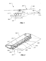
- a rotorcraft 101 having a plurality of rotor blades 103.
- Each rotor blade 103 includes an adaptive twist system 201, according to the preferred embodiment of the present application.
- Rotorcraft 101 includes a fuselage 105, a landing gear 107, and an anti-torque mechanism 109.
- Rotorcraft 101 includes an engine for providing torque to a rotor mast for turning each rotor blade 103 about a rotor mast axis of rotation.
- rotorcraft 101 includes a control system 111 for operating adaptive twist system 201, as discussed further herein. It should be appreciated that rotor blade 103, having adaptive twist system 201, may be implemented on a variety of aircraft.
- a tiltrotor a tilt wing, a gyrocopter, a conventional airplane, and the like
- aircraft may implement rotor blade 103 having adaptive twist system 201.
- any unmanned version of an aircraft may also include rotor blade 103 having adaptive twist system 201.
- adaptive twist system 201 includes a slider mechanism 211 driven by an actuator motor 209.
- Slider mechanism 211 is configured to selectively translate a lower skin 207 relative to a spar 203, thereby reconfiguring the airfoil shape of rotor blade 103 through a resulting twist.
- An alternative embodiment may include slider mechanism 211 configured to translate upper skin 205 relative to spar 203 instead of lower skin 207.
- Slider mechanism 211 is configured to provide structural continuity and high torsional stiffness in rotor blade 103 by continuously providing a structural load path between the structural components being translated. Furthermore, even as lower skin 207 is translated relative to a spar 203, slider mechanism 211 continuously provides a structural load path between lower skin 207 and spar 203.
- rotor blade 103 includes an upper skin 205 and lower skin 207, both of which form upper and lower surfaces of an airfoil shape.
- upper skin 205 and lower skin 207 are structurally joined at a trailing edge 229.
- Spar 203 provides structural support to rotor blade 103 and is generally located along a spanwise direction of rotor blade 103.
- Spar 203 is a structural member that may be of a variety of shapes and sizes.
- spar 203 may be "D" shaped so as to include a hollow portion.
- spar 203 may simply be a beam extending in a spanwise direction.
- the airfoil shape of rotor blade 103 may have angle of incidence that varies over a spanwise length.
- the airfoil shape of rotor blade 103 may have a high angle of incidence near the blade root, while a lower angle of incidence near the blade tip.
- Such an airfoil configuration compensates for the slower rotational speed near the blade root portion of rotor blade 103, as compared to the rotational speed near the blade tip.
- a spar adapter 213 is optionally located between slider mechanism 211 and spar 203.
- a lower skin adapter 215a and 215b are located between slider mechanism 211 and lower skin 207.
- a variety of structural adapters, and combinations thereof, may be used to couple slider mechanism 211 to spar 203 and lower skin 207. It should be appreciated that slider mechanism 211 may alternatively be coupled directly to spar 203 and lower skin 207, instead of employing adapters 215a, 215b, and 213.
- Lower skin adapter 215b preferably extends under a nose cap 227, such that lower skin adapter 215b and nose cap 227 to form a compressive seal, while also allowed sliding movement therebetween.
- Some embodiments may include a thin layer of a material having a low coefficient of friction to minimize frictional resistance and wear between lower skin adapter 215b and nose cap 227.
- Slider mechanism 211 includes a plurality of fixed collars 219a-219d and threaded collars 221a-221c, each fixed collar and threaded collar being located in an alternating configuration.
- a screw drive shaft 217 is operable associated with actuator motor 209 such that motor 209 selectively applies torque to screw drive shaft 217.
- Actuator motor 209 may be any type of actuator motor, such as electric, hydraulic, pneumatic, piezoelectric, to name a few.
- a gearbox may be used to selectively tailor the rotational speed of screw drive shaft 217.
- Each fixed collar 219a-219d is fixed to screw drive shaft 217, as well as being coupled to lower skin 207 via lower skin adapters 215a and 215b.
- actuator motor 209 turns screw drive shaft 217 so that each collar 219a-219d also turns along with screw drive shaft 217.
- a bearing system located within each collar 219a-219d allows a portion of each collar 219a-219d to rotate with screw drive shaft 217, while another portion is fixedly coupled to lower skin 207 via adapters 215a and 215b.
- Each threaded collar 221a-221c is threadingly engaged with screw drive shaft 217, as well as being coupled to spar 203 via spar adapter 213.
- each fixed collar 219a-219d and each threaded collar 221a-221c are located in an alternating configuration, thereby distributing the loading across each member.
- mechanisms other than slider mechanism 211, may be used to translate spar 203 in relation to lower skin 207 in order to induce a twist in rotor blade 103.
- pneumatic pistons may be coupled to spar 203 and lower skin 207 in order to induce a twisting of rotor blade 103.
- screw drive shaft 217 selectively turns in a direction 223, thereby causing lower skin 207 to move in a spanwise direction 225 while spar 203 remains stationary.
- the translation of lower skin 207 relative to spar 203 produces a twisting of rotor blade 103, causing a twisting change to the airfoil shape of rotor blade 103.
- a change to the airfoil shape may include a change to the cross-section airfoil shape itself, as well as a change to the angle of incidence along the spanwise length of rotor blade 103.
- Slider mechanism 211 is configured to maintain structural connectivity between spar 203 and lower skin 207. Because structural connectivity is maintained, high torsional stiffness is maintained in rotor blade 103.
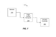
- control system 111 includes an actuator controller 231 for selectively controlling the operation of adaptive twist system 201. More specifically, actuator controller 231 selectively controls the rotation of screw drive shaft 217 via actuator motor 209. Actuator controller 231 sends commands to actuator motor 209. Exemplary commands include a rotational direction command and a speed of rotation command. Actuator controller 231 receives inputs from a flight control computer 235. Flight control computer 235 interprets data from sensors 233 in order to selectively configure the airfoil shape of rotor blade 103 in the most desirable airfoil shape, via adaptive twist system 201. For example, sensors 233 may include an outside air temperature (OAT) sensor, a forward airspeed sensor, gross weight sensor, and altitude sensor, to name a few.
- OAT outside air temperature
- flight control computer 235 can determine that rotorcraft 101 has slowed into a hover flight pattern, thus sending a signal to actuator controller 231 that reconfigures the airfoil shape of rotor blade 103 by twisting rotor blade 103 with adaptive twist system 201.
- adaptive twist system 201 is controlled by an operator of rotorcraft 101, such as a pilot.
- adaptive twist system 201 makes changes to the airfoil shape of rotor blade 103 when the rotorcraft 101 changes between flight modes, such as between a hover mode and a forward flight mode.
- adaptive twist system 201 may be used to change the airfoil shape of rotor blade 103 one or more times within a single revolution about the mast axis of rotation.
- the system of the present application provides significant advantages, including: (1) providing a system for changing the airfoil shape of a rotor blade during operation; (2) providing a system that enables the rotor blade to maintain a high degree of torsional stiffness; and (3) providing a system that maintains structural connectivity between translating parts in the rotor blade.
Landscapes
- Engineering & Computer Science (AREA)
- Mechanical Engineering (AREA)
- Aviation & Aerospace Engineering (AREA)
- Turbine Rotor Nozzle Sealing (AREA)
Description
- The present application relates to a rotor blade for an aircraft. In particular, the present application relates to a system for changing the airfoil shape of a rotor blade.
- A typically rotor blade includes an airfoil shape which is optimized for a certain flight profile. For example, a conventional helicopter may have a rotor blade having airfoil shape that is optimized for hover performance, but as a result, sacrifices an airfoil shape that might otherwise be optimal for forward flight. As a result, attempts have been made in order to adaptively change an airfoil shape during flight so that the airfoil shape can be optimized for changes in flight patterns. One design includes the use of active tabs or flaps on the blade to selectively change the aerodynamic forces about the rotor blade. Another method includes changing the airfoil shape by mechanically twisting the rotor blade through application of a mechanical twisting moment against the torsional stiffness of the blade. In doing so, the rotor blade must be torsionally compliant, or soft, in order to achieve a significant amount of twist in the rotor blade. Torsional compliance in a rotor blade adversely affects rotor blade dynamics, stability, and loading.
-
FR2833571 (A1 - Although the developments in rotor blade design have produced significant improvements, considerable shortcomings remain.
- The novel features believed characteristic of the system of the present application are set forth in the appended claims. However, the system itself, as well as a preferred mode of use, and further objectives and advantages thereof, will best be understood by reference to the following detailed description when read in conjunction with the accompanying drawings, in which the leftmost significant digit(s) in the reference numerals denote(s) the first figure in which the respective reference numerals appear, wherein:
-
Figure 1 is a side view of a rotorcraft with a rotor blade having an adaptive twist system according to the preferred embodiment of the present application; -
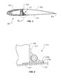
Figure 2 is a partial stylized perspective view of the rotor blade having the adaptive twist system, according to the preferred embodiment of the present application; -
Figure 3 is an end view of a selected portion of the rotor blade ofFigure 2 ; -
Figure 4 is a stylized detail view of a portion of the adaptive twist system taken fromFigure 3 ; -
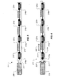
Figure 5 is a stylized view of the adaptive twist system, according to the preferred embodiment of the present application; -
Figure 6 is a stylized view of the adaptive twist system, according to the preferred embodiment of the present application; and -
Figure 7 is a schematic view of a control system for controlling the adaptive twist system, according to the preferred embodiment of the present application. - While the system of the present application is susceptible to various modifications and alternative forms, specific embodiments thereof have been shown by way of example in the drawings and are herein described in detail. It should be understood, however, that the description herein of specific embodiments is not intended to limit the method to the particular forms disclosed, but on the contrary, the intention is to cover all modifications, equivalents, and alternatives falling within the scope of the application as defined by the appended claims.
- In accordance with the invention as defined by the appended claims there is provided an adaptive twist system for a rotor blade and a rotor craft.
- Illustrative embodiments of the system of the present application are described below. In the interest of clarity, not all features of an actual implementation are described in this specification. It will of course be appreciated that in the development of any such actual embodiment, numerous implementation-specific decisions must be made to achieve the developer's specific goals, such as compliance with system-related and business-related constraints, which will vary from one implementation to another. Moreover, it will be appreciated that such a development effort might be complex and time-consuming but would nevertheless be a routine undertaking for those of ordinary skill in the art having the benefit of this disclosure.
- In the specification, reference may be made to the spatial relationships between various components and to the spatial orientation of various aspects of components as the devices are depicted in the attached drawings. However, as will be recognized by those skilled in the art after a complete reading of the present application, the devices, members, apparatuses, etc. described herein may be positioned in any desired orientation. Thus, the use of terms such as "above," "below," "upper," "lower," or other like terms to describe a spatial relationship between various components or to describe the spatial orientation of aspects of such components should be understood to describe a relative relationship between the components or a spatial orientation of aspects of such components, respectively, as the device described herein may be oriented in any desired direction.
- Referring to
Figure 1 , arotorcraft 101 is depicted having a plurality ofrotor blades 103. Eachrotor blade 103 includes anadaptive twist system 201, according to the preferred embodiment of the present application. Rotorcraft 101 includes afuselage 105, alanding gear 107, and ananti-torque mechanism 109. Rotorcraft 101 includes an engine for providing torque to a rotor mast for turning eachrotor blade 103 about a rotor mast axis of rotation. Furthermore, rotorcraft 101 includes acontrol system 111 for operatingadaptive twist system 201, as discussed further herein. It should be appreciated thatrotor blade 103, havingadaptive twist system 201, may be implemented on a variety of aircraft. For example, a tiltrotor, a tilt wing, a gyrocopter, a conventional airplane, and the like, are examples of aircraft that may implementrotor blade 103 havingadaptive twist system 201. Furthermore, any unmanned version of an aircraft may also includerotor blade 103 havingadaptive twist system 201. - Referring to
Figures 2 and3 ,adaptive twist system 201 includes aslider mechanism 211 driven by anactuator motor 209.Slider mechanism 211 is configured to selectively translate alower skin 207 relative to aspar 203, thereby reconfiguring the airfoil shape ofrotor blade 103 through a resulting twist. An alternative embodiment may includeslider mechanism 211 configured to translateupper skin 205 relative tospar 203 instead oflower skin 207.Slider mechanism 211 is configured to provide structural continuity and high torsional stiffness inrotor blade 103 by continuously providing a structural load path between the structural components being translated. Furthermore, even aslower skin 207 is translated relative to aspar 203,slider mechanism 211 continuously provides a structural load path betweenlower skin 207 andspar 203. - Still referring to
Figures 2 and3 ,rotor blade 103 includes anupper skin 205 andlower skin 207, both of which form upper and lower surfaces of an airfoil shape. Preferably,upper skin 205 andlower skin 207 are structurally joined at atrailing edge 229. Spar 203 provides structural support torotor blade 103 and is generally located along a spanwise direction ofrotor blade 103. Spar 203 is a structural member that may be of a variety of shapes and sizes. For example,spar 203 may be "D" shaped so as to include a hollow portion. Further,spar 203 may simply be a beam extending in a spanwise direction. It should be appreciated that the airfoil shape ofrotor blade 103 may have angle of incidence that varies over a spanwise length. For example, the airfoil shape ofrotor blade 103 may have a high angle of incidence near the blade root, while a lower angle of incidence near the blade tip. Such an airfoil configuration compensates for the slower rotational speed near the blade root portion ofrotor blade 103, as compared to the rotational speed near the blade tip. - Referring now also to
Figure 4 , a partial end view ofrotor blade 103 is illustrated. Aspar adapter 213 is optionally located betweenslider mechanism 211 andspar 203. Alower skin adapter slider mechanism 211 andlower skin 207. However, a variety of structural adapters, and combinations thereof, may be used to coupleslider mechanism 211 to spar 203 andlower skin 207. It should be appreciated thatslider mechanism 211 may alternatively be coupled directly to spar 203 andlower skin 207, instead of employingadapters Lower skin adapter 215b preferably extends under anose cap 227, such thatlower skin adapter 215b andnose cap 227 to form a compressive seal, while also allowed sliding movement therebetween. Some embodiments may include a thin layer of a material having a low coefficient of friction to minimize frictional resistance and wear betweenlower skin adapter 215b andnose cap 227. - Referring now also to
Figures 5 and 6 ,slider mechanism 211 is further illustrated.Slider mechanism 211 includes a plurality of fixedcollars 219a-219d and threadedcollars 221a-221c, each fixed collar and threaded collar being located in an alternating configuration. Ascrew drive shaft 217 is operable associated withactuator motor 209 such thatmotor 209 selectively applies torque to screwdrive shaft 217.Actuator motor 209 may be any type of actuator motor, such as electric, hydraulic, pneumatic, piezoelectric, to name a few. A gearbox may be used to selectively tailor the rotational speed ofscrew drive shaft 217. Each fixedcollar 219a-219d is fixed to screwdrive shaft 217, as well as being coupled tolower skin 207 vialower skin adapters actuator motor 209 turnsscrew drive shaft 217 so that eachcollar 219a-219d also turns along withscrew drive shaft 217. A bearing system located within eachcollar 219a-219d allows a portion of eachcollar 219a-219d to rotate withscrew drive shaft 217, while another portion is fixedly coupled tolower skin 207 viaadapters collar 221a-221c is threadingly engaged withscrew drive shaft 217, as well as being coupled to spar 203 viaspar adapter 213. As such, constant structural connectivity is maintained betweenspar 203 andlower skin 207 throughslider mechanism 211. More specifically, loads are transferred betweenspar 103 andlower skin 107 through the structural connection between eachfixed collar 219a-219d and screwdrive shaft 217, as well as betweenscrew drive shaft 217 and each threadedcollar 221a-221c. As such, it is preferred that eachfixed collar 219a-219d and each threadedcollar 221a-221c are located in an alternating configuration, thereby distributing the loading across each member. - It should be appreciated that mechanisms, other than
slider mechanism 211, may be used to translatespar 203 in relation tolower skin 207 in order to induce a twist inrotor blade 103. For example, pneumatic pistons may be coupled to spar 203 andlower skin 207 in order to induce a twisting ofrotor blade 103. - During operation, screw
drive shaft 217 selectively turns in adirection 223, thereby causinglower skin 207 to move in aspanwise direction 225 whilespar 203 remains stationary. The translation oflower skin 207 relative to spar 203 produces a twisting ofrotor blade 103, causing a twisting change to the airfoil shape ofrotor blade 103. A change to the airfoil shape may include a change to the cross-section airfoil shape itself, as well as a change to the angle of incidence along the spanwise length ofrotor blade 103.Slider mechanism 211 is configured to maintain structural connectivity betweenspar 203 andlower skin 207. Because structural connectivity is maintained, high torsional stiffness is maintained inrotor blade 103. - Referring to
Figure 7 ,control system 111 includes anactuator controller 231 for selectively controlling the operation ofadaptive twist system 201. More specifically,actuator controller 231 selectively controls the rotation ofscrew drive shaft 217 viaactuator motor 209.Actuator controller 231 sends commands toactuator motor 209. Exemplary commands include a rotational direction command and a speed of rotation command.Actuator controller 231 receives inputs from aflight control computer 235.Flight control computer 235 interprets data fromsensors 233 in order to selectively configure the airfoil shape ofrotor blade 103 in the most desirable airfoil shape, viaadaptive twist system 201. For example,sensors 233 may include an outside air temperature (OAT) sensor, a forward airspeed sensor, gross weight sensor, and altitude sensor, to name a few. During operation ofrotorcraft 101,flight control computer 235 can determine thatrotorcraft 101 has slowed into a hover flight pattern, thus sending a signal toactuator controller 231 that reconfigures the airfoil shape ofrotor blade 103 by twistingrotor blade 103 withadaptive twist system 201. In an alternative embodiment,adaptive twist system 201 is controlled by an operator ofrotorcraft 101, such as a pilot. Furthermore, it is preferred thatadaptive twist system 201 makes changes to the airfoil shape ofrotor blade 103 when therotorcraft 101 changes between flight modes, such as between a hover mode and a forward flight mode. However, it is also contemplated thatadaptive twist system 201 may be used to change the airfoil shape ofrotor blade 103 one or more times within a single revolution about the mast axis of rotation. - The system of the present application provides significant advantages, including: (1) providing a system for changing the airfoil shape of a rotor blade during operation; (2) providing a system that enables the rotor blade to maintain a high degree of torsional stiffness; and (3) providing a system that maintains structural connectivity between translating parts in the rotor blade.
- The particular embodiments disclosed above are illustrative only, as the application may be modified and practiced in different but equivalent manners apparent to those skilled in the art having the benefit of the teachings herein. Furthermore, no limitations are intended to the details of construction or design herein shown, other than as described in the claims below. It is therefore evident that the particular embodiments disclosed above may be altered or modified and all such variations are considered within the scope of the application. Accordingly, the protection sought herein is as set forth in the claims below. It is apparent that a system with significant advantages has been described and illustrated. Although the system of the present application is shown in a limited number of forms, it is not limited to just these forms, but is amenable to various changes and modifications within the scope of the appended claims. modifications.
Claims (9)
- An adaptive twist system (201) for a rotor blade (103), the adaptive twist system (201) comprising:a slider mechanism (211) coupled to a spar (203) and to a skin (207), the slider mechanism (211) configured to provide structural connectivity between the spar (203) and the skin (207);an actuator (209) configured to drive the slider mechanism (211);wherein the slider mechanism (211) is configured to translate the skin (207) relative to the spar (203) in a spanwise direction, thereby causing the rotor blade to twist;wherein the slider mechanism (211) comprises:a screw drive shaft (217) located in spanwise direction along the rotor blade;a fixed collar (219a-219d) coupled to the skin, the fixed collar including a bearing to allow a first portion of the fixed collar to rotate along with the screw drive (217), while a second portion of the fixed collar remains fixed relative to the skin (207);a threaded collar (221a-221c) coupled to the spar (203), the threaded collar including receiving threads such that rotation of the screw drive shaft (217) causes the threaded collar (221a-221c) to translate relative to the fixed collar (219a-219d).
- The adaptive twist system (201) according to claim 1, wherein the skin is a lower skin.
- The adaptive twist system (201) according to claim 1, further comprising:a spar adapter (213) located between the threaded collar (221a-221c) and the spar (203).
- The adaptive twist system (201) according to claim 1, further comprising:a skin adapter (215a, 215b) located between the fixed collar (219a-219d) and the skin (207).
- The adaptive twist system (201) according to claim 1, further comprising:a low-friction layer between a skin adapter and a nose cap, the low-friction layer being configured to prevent wear during translation of the skin adapter relative to the nose cap.
- A rotorcraft (101) comprising:a plurality of rotor blades (103), each rotor blade having an adaptive twist system (201) according to any one or more of claims 1 to 5.
- The rotor craft (101) according to claim 6, wherein the adaptive twist system further comprises a control system (231) configured to automatically control the adaptive twist system (201) so that a shape of each rotor blade is twisted into an optimal shape during operation of the rotorcraft.
- The rotorcraft (101) according to claim 7, wherein the control system (231) automatically operates the adaptive twist system (201) to twist the rotor blade when the rotorcraft converts from a hover flight mode to a forward flight mode.
- The rotorcraft (101) according to claim 7, wherein the control system (231) automatically operates the adaptive twist system (201) to twist the rotor blade when the rotorcraft converts from a forward flight mode to a hover flight mode.
Applications Claiming Priority (1)
| Application Number | Priority Date | Filing Date | Title |
|---|---|---|---|
| PCT/US2010/056500 WO2012064337A1 (en) | 2010-11-12 | 2010-11-12 | Adaptive twist system for a rotor blade |
Publications (3)
| Publication Number | Publication Date |
|---|---|
| EP2619085A1 EP2619085A1 (en) | 2013-07-31 |
| EP2619085A4 EP2619085A4 (en) | 2014-04-02 |
| EP2619085B1 true EP2619085B1 (en) | 2015-06-03 |
Family
ID=46051226
Family Applications (1)
| Application Number | Title | Priority Date | Filing Date |
|---|---|---|---|
| EP10859549.7A Not-in-force EP2619085B1 (en) | 2010-11-12 | 2010-11-12 | Adaptive twist system for a rotor blade |
Country Status (4)
| Country | Link |
|---|---|
| US (1) | US8662843B2 (en) |
| EP (1) | EP2619085B1 (en) |
| CA (1) | CA2817089C (en) |
| WO (1) | WO2012064337A1 (en) |
Families Citing this family (10)
| Publication number | Priority date | Publication date | Assignee | Title |
|---|---|---|---|---|
| FR3007737B1 (en) * | 2013-06-26 | 2017-07-14 | Eurocopter France | BLADE WITH RIGIDITY IN REDUCED TORSION AND ROTOR PROVIDED WITH SUCH A BLADE |
| FR3011818B1 (en) * | 2013-10-11 | 2015-12-25 | Eurocopter France | ADAPTIVE ROTATING BLADE, AND AIRCRAFT PROVIDED WITH SUCH A BLADE |
| US10207793B2 (en) | 2016-11-30 | 2019-02-19 | Bell Helicopter Textron Inc. | Rotor blade having variable twist |
| US10215157B2 (en) * | 2017-01-04 | 2019-02-26 | General Electric Company | Methods for controlling wind turbine with thrust control twist compensation |
| US20190118935A1 (en) * | 2017-10-24 | 2019-04-25 | General Atomics Aeronautical Systems, Inc. | Shape changing aircraft blade |
| CN109625310B (en) * | 2018-12-02 | 2022-04-01 | 中国航空工业集团公司沈阳飞机设计研究所 | Method for obtaining torsion angle of each station in double-pipe wing beam |
| USD920216S1 (en) * | 2020-01-03 | 2021-05-25 | Bell Textron Inc. | Combined stator and spindle for a ducted rotor |
| US12122507B2 (en) * | 2021-06-22 | 2024-10-22 | Lockheed Martin Corporation | Real time rotor head moment measurement, control, and limiting |
| CN116331479B (en) * | 2023-04-14 | 2025-07-15 | 南京航空航天大学 | A rotor with variable negative torque and a rotor negative torque regulating device |
| CN118034071B (en) * | 2024-04-15 | 2024-07-02 | 四川沃飞长空科技发展有限公司 | Aircraft control distribution method, device, aircraft, storage medium and product |
Family Cites Families (7)
| Publication number | Priority date | Publication date | Assignee | Title |
|---|---|---|---|---|
| US5320491A (en) * | 1992-07-09 | 1994-06-14 | Northern Power Systems, Inc. | Wind turbine rotor aileron |
| US6382556B1 (en) * | 1999-12-20 | 2002-05-07 | Roger N. C. Pham | VTOL airplane with only one tiltable prop-rotor |
| DE10055961B4 (en) | 2000-11-11 | 2004-09-09 | Eads Deutschland Gmbh | Variable wing area with adjustable profile shape that extends in the span direction |
| FR2833571B1 (en) | 2001-12-19 | 2004-04-02 | Onera (Off Nat Aerospatiale) | AERODYNAMIC OR HYDRODYNAMIC PORTABLE SURFACE |
| US9039372B2 (en) * | 2007-04-30 | 2015-05-26 | Vestas Wind Systems A/S | Wind turbine blade |
| FR2924681B1 (en) * | 2007-12-05 | 2010-01-01 | Onera (Off Nat Aerospatiale) | AERODYNAMIC AERODYNAMIC ELEMENT DEFORMABLE IN TORSION |
| US8246303B2 (en) * | 2008-07-29 | 2012-08-21 | The United States Of America As Represented By The Secretary Of The Navy | Active twist hollow beam system |
-
2010
- 2010-11-12 WO PCT/US2010/056500 patent/WO2012064337A1/en not_active Ceased
- 2010-11-12 CA CA2817089A patent/CA2817089C/en active Active
- 2010-11-12 EP EP10859549.7A patent/EP2619085B1/en not_active Not-in-force
- 2010-11-12 US US13/703,766 patent/US8662843B2/en active Active
Also Published As
| Publication number | Publication date |
|---|---|
| CA2817089A1 (en) | 2012-05-18 |
| WO2012064337A1 (en) | 2012-05-18 |
| CA2817089C (en) | 2016-02-16 |
| US8662843B2 (en) | 2014-03-04 |
| EP2619085A4 (en) | 2014-04-02 |
| EP2619085A1 (en) | 2013-07-31 |
| US20130089422A1 (en) | 2013-04-11 |
Similar Documents
| Publication | Publication Date | Title |
|---|---|---|
| CA2817089C (en) | Adaptive twist system for a rotor blade | |
| US10822076B2 (en) | Dual rotor, rotary wing aircraft | |
| US11021241B2 (en) | Dual rotor, rotary wing aircraft | |
| EP3483065B1 (en) | Multirotor aircraft with collective for autorotation | |
| US10011349B2 (en) | Tiltrotor aircraft having rotatable wing extensions | |
| EP2673474B1 (en) | Reconfigurable rotor blade | |
| EP2595881B1 (en) | Airfoil shaped tail boom | |
| EP2222554B1 (en) | Multi-bladed rotor system for rotorcraft | |
| EP2604513B1 (en) | Blade-pitch control system with feedback lever | |
| EP3406522B1 (en) | Rotor assemblies and related control systems | |
| US20180057148A1 (en) | Tiltrotor Aircraft having Active Wing Extensions | |
| EP3333074B1 (en) | Soft-in-plane proprotor systems | |
| WO2008085192A2 (en) | Rotorcraft with opposing roll mast moments, and related methods | |
| EP3323720B1 (en) | Proprotor systems for tiltrotor aircraft | |
| US20180244380A1 (en) | Apparatus And Method For Roll Moment Equalization At High Advance Ratios For Rotary Wing Aircraft | |
| US5263846A (en) | Self-actuated rotor system | |
| EP2733072B1 (en) | Blade-pitch control system with indexing swashplate |
Legal Events
| Date | Code | Title | Description |
|---|---|---|---|
| PUAI | Public reference made under article 153(3) epc to a published international application that has entered the european phase |
Free format text: ORIGINAL CODE: 0009012 |
|
| 17P | Request for examination filed |
Effective date: 20130426 |
|
| AK | Designated contracting states |
Kind code of ref document: A1 Designated state(s): AL AT BE BG CH CY CZ DE DK EE ES FI FR GB GR HR HU IE IS IT LI LT LU LV MC MK MT NL NO PL PT RO RS SE SI SK SM TR |
|
| DAX | Request for extension of the european patent (deleted) | ||
| A4 | Supplementary search report drawn up and despatched |
Effective date: 20140228 |
|
| RIC1 | Information provided on ipc code assigned before grant |
Ipc: B64C 21/00 20060101AFI20140224BHEP |
|
| GRAP | Despatch of communication of intention to grant a patent |
Free format text: ORIGINAL CODE: EPIDOSNIGR1 |
|
| GRAS | Grant fee paid |
Free format text: ORIGINAL CODE: EPIDOSNIGR3 |
|
| INTG | Intention to grant announced |
Effective date: 20150401 |
|
| GRAA | (expected) grant |
Free format text: ORIGINAL CODE: 0009210 |
|
| AK | Designated contracting states |
Kind code of ref document: B1 Designated state(s): AL AT BE BG CH CY CZ DE DK EE ES FI FR GB GR HR HU IE IS IT LI LT LU LV MC MK MT NL NO PL PT RO RS SE SI SK SM TR |
|
| REG | Reference to a national code |
Ref country code: GB Ref legal event code: FG4D |
|
| REG | Reference to a national code |
Ref country code: CH Ref legal event code: EP |
|
| REG | Reference to a national code |
Ref country code: AT Ref legal event code: REF Ref document number: 729765 Country of ref document: AT Kind code of ref document: T Effective date: 20150715 Ref country code: IE Ref legal event code: FG4D |
|
| REG | Reference to a national code |
Ref country code: DE Ref legal event code: R096 Ref document number: 602010025117 Country of ref document: DE |
|
| REG | Reference to a national code |
Ref country code: AT Ref legal event code: MK05 Ref document number: 729765 Country of ref document: AT Kind code of ref document: T Effective date: 20150603 |
|
| PG25 | Lapsed in a contracting state [announced via postgrant information from national office to epo] |
Ref country code: ES Free format text: LAPSE BECAUSE OF FAILURE TO SUBMIT A TRANSLATION OF THE DESCRIPTION OR TO PAY THE FEE WITHIN THE PRESCRIBED TIME-LIMIT Effective date: 20150603 Ref country code: HR Free format text: LAPSE BECAUSE OF FAILURE TO SUBMIT A TRANSLATION OF THE DESCRIPTION OR TO PAY THE FEE WITHIN THE PRESCRIBED TIME-LIMIT Effective date: 20150603 Ref country code: FI Free format text: LAPSE BECAUSE OF FAILURE TO SUBMIT A TRANSLATION OF THE DESCRIPTION OR TO PAY THE FEE WITHIN THE PRESCRIBED TIME-LIMIT Effective date: 20150603 Ref country code: LT Free format text: LAPSE BECAUSE OF FAILURE TO SUBMIT A TRANSLATION OF THE DESCRIPTION OR TO PAY THE FEE WITHIN THE PRESCRIBED TIME-LIMIT Effective date: 20150603 Ref country code: NO Free format text: LAPSE BECAUSE OF FAILURE TO SUBMIT A TRANSLATION OF THE DESCRIPTION OR TO PAY THE FEE WITHIN THE PRESCRIBED TIME-LIMIT Effective date: 20150903 |
|
| REG | Reference to a national code |
Ref country code: NL Ref legal event code: MP Effective date: 20150603 |
|
| REG | Reference to a national code |
Ref country code: FR Ref legal event code: PLFP Year of fee payment: 6 |
|
| REG | Reference to a national code |
Ref country code: LT Ref legal event code: MG4D |
|
| PG25 | Lapsed in a contracting state [announced via postgrant information from national office to epo] |
Ref country code: LV Free format text: LAPSE BECAUSE OF FAILURE TO SUBMIT A TRANSLATION OF THE DESCRIPTION OR TO PAY THE FEE WITHIN THE PRESCRIBED TIME-LIMIT Effective date: 20150603 Ref country code: BG Free format text: LAPSE BECAUSE OF FAILURE TO SUBMIT A TRANSLATION OF THE DESCRIPTION OR TO PAY THE FEE WITHIN THE PRESCRIBED TIME-LIMIT Effective date: 20150903 Ref country code: RS Free format text: LAPSE BECAUSE OF FAILURE TO SUBMIT A TRANSLATION OF THE DESCRIPTION OR TO PAY THE FEE WITHIN THE PRESCRIBED TIME-LIMIT Effective date: 20150603 Ref country code: AT Free format text: LAPSE BECAUSE OF FAILURE TO SUBMIT A TRANSLATION OF THE DESCRIPTION OR TO PAY THE FEE WITHIN THE PRESCRIBED TIME-LIMIT Effective date: 20150603 Ref country code: GR Free format text: LAPSE BECAUSE OF FAILURE TO SUBMIT A TRANSLATION OF THE DESCRIPTION OR TO PAY THE FEE WITHIN THE PRESCRIBED TIME-LIMIT Effective date: 20150904 |
|
| PG25 | Lapsed in a contracting state [announced via postgrant information from national office to epo] |
Ref country code: EE Free format text: LAPSE BECAUSE OF FAILURE TO SUBMIT A TRANSLATION OF THE DESCRIPTION OR TO PAY THE FEE WITHIN THE PRESCRIBED TIME-LIMIT Effective date: 20150603 |
|
| PG25 | Lapsed in a contracting state [announced via postgrant information from national office to epo] |
Ref country code: SK Free format text: LAPSE BECAUSE OF FAILURE TO SUBMIT A TRANSLATION OF THE DESCRIPTION OR TO PAY THE FEE WITHIN THE PRESCRIBED TIME-LIMIT Effective date: 20150603 Ref country code: PL Free format text: LAPSE BECAUSE OF FAILURE TO SUBMIT A TRANSLATION OF THE DESCRIPTION OR TO PAY THE FEE WITHIN THE PRESCRIBED TIME-LIMIT Effective date: 20150603 Ref country code: PT Free format text: LAPSE BECAUSE OF FAILURE TO SUBMIT A TRANSLATION OF THE DESCRIPTION OR TO PAY THE FEE WITHIN THE PRESCRIBED TIME-LIMIT Effective date: 20151006 Ref country code: RO Free format text: LAPSE BECAUSE OF NON-PAYMENT OF DUE FEES Effective date: 20150603 Ref country code: IS Free format text: LAPSE BECAUSE OF FAILURE TO SUBMIT A TRANSLATION OF THE DESCRIPTION OR TO PAY THE FEE WITHIN THE PRESCRIBED TIME-LIMIT Effective date: 20151003 Ref country code: CZ Free format text: LAPSE BECAUSE OF FAILURE TO SUBMIT A TRANSLATION OF THE DESCRIPTION OR TO PAY THE FEE WITHIN THE PRESCRIBED TIME-LIMIT Effective date: 20150603 |
|
| REG | Reference to a national code |
Ref country code: DE Ref legal event code: R097 Ref document number: 602010025117 Country of ref document: DE |
|
| PLBE | No opposition filed within time limit |
Free format text: ORIGINAL CODE: 0009261 |
|
| STAA | Information on the status of an ep patent application or granted ep patent |
Free format text: STATUS: NO OPPOSITION FILED WITHIN TIME LIMIT |
|
| PG25 | Lapsed in a contracting state [announced via postgrant information from national office to epo] |
Ref country code: DK Free format text: LAPSE BECAUSE OF FAILURE TO SUBMIT A TRANSLATION OF THE DESCRIPTION OR TO PAY THE FEE WITHIN THE PRESCRIBED TIME-LIMIT Effective date: 20150603 |
|
| 26N | No opposition filed |
Effective date: 20160304 |
|
| PG25 | Lapsed in a contracting state [announced via postgrant information from national office to epo] |
Ref country code: SI Free format text: LAPSE BECAUSE OF FAILURE TO SUBMIT A TRANSLATION OF THE DESCRIPTION OR TO PAY THE FEE WITHIN THE PRESCRIBED TIME-LIMIT Effective date: 20150603 |
|
| PG25 | Lapsed in a contracting state [announced via postgrant information from national office to epo] |
Ref country code: LU Free format text: LAPSE BECAUSE OF FAILURE TO SUBMIT A TRANSLATION OF THE DESCRIPTION OR TO PAY THE FEE WITHIN THE PRESCRIBED TIME-LIMIT Effective date: 20151112 Ref country code: MC Free format text: LAPSE BECAUSE OF FAILURE TO SUBMIT A TRANSLATION OF THE DESCRIPTION OR TO PAY THE FEE WITHIN THE PRESCRIBED TIME-LIMIT Effective date: 20150603 |
|
| REG | Reference to a national code |
Ref country code: CH Ref legal event code: PL |
|
| PG25 | Lapsed in a contracting state [announced via postgrant information from national office to epo] |
Ref country code: CH Free format text: LAPSE BECAUSE OF NON-PAYMENT OF DUE FEES Effective date: 20151130 Ref country code: LI Free format text: LAPSE BECAUSE OF NON-PAYMENT OF DUE FEES Effective date: 20151130 |
|
| REG | Reference to a national code |
Ref country code: IE Ref legal event code: MM4A |
|
| PG25 | Lapsed in a contracting state [announced via postgrant information from national office to epo] |
Ref country code: IE Free format text: LAPSE BECAUSE OF NON-PAYMENT OF DUE FEES Effective date: 20151112 |
|
| REG | Reference to a national code |
Ref country code: FR Ref legal event code: PLFP Year of fee payment: 7 |
|
| PG25 | Lapsed in a contracting state [announced via postgrant information from national office to epo] |
Ref country code: BE Free format text: LAPSE BECAUSE OF FAILURE TO SUBMIT A TRANSLATION OF THE DESCRIPTION OR TO PAY THE FEE WITHIN THE PRESCRIBED TIME-LIMIT Effective date: 20150603 |
|
| PG25 | Lapsed in a contracting state [announced via postgrant information from national office to epo] |
Ref country code: SM Free format text: LAPSE BECAUSE OF FAILURE TO SUBMIT A TRANSLATION OF THE DESCRIPTION OR TO PAY THE FEE WITHIN THE PRESCRIBED TIME-LIMIT Effective date: 20150603 Ref country code: HU Free format text: LAPSE BECAUSE OF FAILURE TO SUBMIT A TRANSLATION OF THE DESCRIPTION OR TO PAY THE FEE WITHIN THE PRESCRIBED TIME-LIMIT; INVALID AB INITIO Effective date: 20101112 |
|
| PG25 | Lapsed in a contracting state [announced via postgrant information from national office to epo] |
Ref country code: NL Free format text: LAPSE BECAUSE OF FAILURE TO SUBMIT A TRANSLATION OF THE DESCRIPTION OR TO PAY THE FEE WITHIN THE PRESCRIBED TIME-LIMIT Effective date: 20150603 Ref country code: CY Free format text: LAPSE BECAUSE OF FAILURE TO SUBMIT A TRANSLATION OF THE DESCRIPTION OR TO PAY THE FEE WITHIN THE PRESCRIBED TIME-LIMIT Effective date: 20150603 Ref country code: SE Free format text: LAPSE BECAUSE OF FAILURE TO SUBMIT A TRANSLATION OF THE DESCRIPTION OR TO PAY THE FEE WITHIN THE PRESCRIBED TIME-LIMIT Effective date: 20150603 |
|
| PG25 | Lapsed in a contracting state [announced via postgrant information from national office to epo] |
Ref country code: MT Free format text: LAPSE BECAUSE OF FAILURE TO SUBMIT A TRANSLATION OF THE DESCRIPTION OR TO PAY THE FEE WITHIN THE PRESCRIBED TIME-LIMIT Effective date: 20150603 |
|
| REG | Reference to a national code |
Ref country code: FR Ref legal event code: PLFP Year of fee payment: 8 |
|
| PG25 | Lapsed in a contracting state [announced via postgrant information from national office to epo] |
Ref country code: MK Free format text: LAPSE BECAUSE OF FAILURE TO SUBMIT A TRANSLATION OF THE DESCRIPTION OR TO PAY THE FEE WITHIN THE PRESCRIBED TIME-LIMIT Effective date: 20150603 Ref country code: TR Free format text: LAPSE BECAUSE OF FAILURE TO SUBMIT A TRANSLATION OF THE DESCRIPTION OR TO PAY THE FEE WITHIN THE PRESCRIBED TIME-LIMIT Effective date: 20150603 |
|
| PG25 | Lapsed in a contracting state [announced via postgrant information from national office to epo] |
Ref country code: AL Free format text: LAPSE BECAUSE OF FAILURE TO SUBMIT A TRANSLATION OF THE DESCRIPTION OR TO PAY THE FEE WITHIN THE PRESCRIBED TIME-LIMIT Effective date: 20150603 |
|
| P01 | Opt-out of the competence of the unified patent court (upc) registered |
Effective date: 20230602 |
|
| PGFP | Annual fee paid to national office [announced via postgrant information from national office to epo] |
Ref country code: GB Payment date: 20231127 Year of fee payment: 14 |
|
| PGFP | Annual fee paid to national office [announced via postgrant information from national office to epo] |
Ref country code: IT Payment date: 20231122 Year of fee payment: 14 Ref country code: FR Payment date: 20231127 Year of fee payment: 14 Ref country code: DE Payment date: 20231129 Year of fee payment: 14 |
|
| REG | Reference to a national code |
Ref country code: DE Ref legal event code: R119 Ref document number: 602010025117 Country of ref document: DE |
|
| GBPC | Gb: european patent ceased through non-payment of renewal fee |
Effective date: 20241112 |
|
| PG25 | Lapsed in a contracting state [announced via postgrant information from national office to epo] |
Ref country code: DE Free format text: LAPSE BECAUSE OF NON-PAYMENT OF DUE FEES Effective date: 20250603 |
|
| PG25 | Lapsed in a contracting state [announced via postgrant information from national office to epo] |
Ref country code: IT Free format text: LAPSE BECAUSE OF NON-PAYMENT OF DUE FEES Effective date: 20241112 |
|
| PG25 | Lapsed in a contracting state [announced via postgrant information from national office to epo] |
Ref country code: GB Free format text: LAPSE BECAUSE OF NON-PAYMENT OF DUE FEES Effective date: 20241112 |
|
| PG25 | Lapsed in a contracting state [announced via postgrant information from national office to epo] |
Ref country code: FR Free format text: LAPSE BECAUSE OF NON-PAYMENT OF DUE FEES Effective date: 20241130 |