EP3536571A1 - Electric brake device - Google Patents
Electric brake device Download PDFInfo
- Publication number
- EP3536571A1 EP3536571A1 EP17867557.5A EP17867557A EP3536571A1 EP 3536571 A1 EP3536571 A1 EP 3536571A1 EP 17867557 A EP17867557 A EP 17867557A EP 3536571 A1 EP3536571 A1 EP 3536571A1
- Authority
- EP
- European Patent Office
- Prior art keywords
- braking force
- current
- angle
- electric motor
- phase
- Prior art date
- Legal status (The legal status is an assumption and is not a legal conclusion. Google has not performed a legal analysis and makes no representation as to the accuracy of the status listed.)
- Granted
Links
Images



Classifications
-
- B—PERFORMING OPERATIONS; TRANSPORTING
- B60—VEHICLES IN GENERAL
- B60T—VEHICLE BRAKE CONTROL SYSTEMS OR PARTS THEREOF; BRAKE CONTROL SYSTEMS OR PARTS THEREOF, IN GENERAL; ARRANGEMENT OF BRAKING ELEMENTS ON VEHICLES IN GENERAL; PORTABLE DEVICES FOR PREVENTING UNWANTED MOVEMENT OF VEHICLES; VEHICLE MODIFICATIONS TO FACILITATE COOLING OF BRAKES
- B60T8/00—Arrangements for adjusting wheel-braking force to meet varying vehicular or ground-surface conditions, e.g. limiting or varying distribution of braking force
- B60T8/17—Using electrical or electronic regulation means to control braking
-
- B—PERFORMING OPERATIONS; TRANSPORTING
- B60—VEHICLES IN GENERAL
- B60T—VEHICLE BRAKE CONTROL SYSTEMS OR PARTS THEREOF; BRAKE CONTROL SYSTEMS OR PARTS THEREOF, IN GENERAL; ARRANGEMENT OF BRAKING ELEMENTS ON VEHICLES IN GENERAL; PORTABLE DEVICES FOR PREVENTING UNWANTED MOVEMENT OF VEHICLES; VEHICLE MODIFICATIONS TO FACILITATE COOLING OF BRAKES
- B60T13/00—Transmitting braking action from initiating means to ultimate brake actuator with power assistance or drive; Brake systems incorporating such transmitting means, e.g. air-pressure brake systems
- B60T13/74—Transmitting braking action from initiating means to ultimate brake actuator with power assistance or drive; Brake systems incorporating such transmitting means, e.g. air-pressure brake systems with electrical assistance or drive
- B60T13/741—Transmitting braking action from initiating means to ultimate brake actuator with power assistance or drive; Brake systems incorporating such transmitting means, e.g. air-pressure brake systems with electrical assistance or drive acting on an ultimate actuator
-
- B—PERFORMING OPERATIONS; TRANSPORTING
- B60—VEHICLES IN GENERAL
- B60T—VEHICLE BRAKE CONTROL SYSTEMS OR PARTS THEREOF; BRAKE CONTROL SYSTEMS OR PARTS THEREOF, IN GENERAL; ARRANGEMENT OF BRAKING ELEMENTS ON VEHICLES IN GENERAL; PORTABLE DEVICES FOR PREVENTING UNWANTED MOVEMENT OF VEHICLES; VEHICLE MODIFICATIONS TO FACILITATE COOLING OF BRAKES
- B60T1/00—Arrangements of braking elements, i.e. of those parts where braking effect occurs specially for vehicles
- B60T1/02—Arrangements of braking elements, i.e. of those parts where braking effect occurs specially for vehicles acting by retarding wheels
- B60T1/06—Arrangements of braking elements, i.e. of those parts where braking effect occurs specially for vehicles acting by retarding wheels acting otherwise than on tread, e.g. employing rim, drum, disc, or transmission or on double wheels
- B60T1/065—Arrangements of braking elements, i.e. of those parts where braking effect occurs specially for vehicles acting by retarding wheels acting otherwise than on tread, e.g. employing rim, drum, disc, or transmission or on double wheels employing disc
-
- B—PERFORMING OPERATIONS; TRANSPORTING
- B60—VEHICLES IN GENERAL
- B60T—VEHICLE BRAKE CONTROL SYSTEMS OR PARTS THEREOF; BRAKE CONTROL SYSTEMS OR PARTS THEREOF, IN GENERAL; ARRANGEMENT OF BRAKING ELEMENTS ON VEHICLES IN GENERAL; PORTABLE DEVICES FOR PREVENTING UNWANTED MOVEMENT OF VEHICLES; VEHICLE MODIFICATIONS TO FACILITATE COOLING OF BRAKES
- B60T13/00—Transmitting braking action from initiating means to ultimate brake actuator with power assistance or drive; Brake systems incorporating such transmitting means, e.g. air-pressure brake systems
- B60T13/74—Transmitting braking action from initiating means to ultimate brake actuator with power assistance or drive; Brake systems incorporating such transmitting means, e.g. air-pressure brake systems with electrical assistance or drive
-
- B—PERFORMING OPERATIONS; TRANSPORTING
- B60—VEHICLES IN GENERAL
- B60T—VEHICLE BRAKE CONTROL SYSTEMS OR PARTS THEREOF; BRAKE CONTROL SYSTEMS OR PARTS THEREOF, IN GENERAL; ARRANGEMENT OF BRAKING ELEMENTS ON VEHICLES IN GENERAL; PORTABLE DEVICES FOR PREVENTING UNWANTED MOVEMENT OF VEHICLES; VEHICLE MODIFICATIONS TO FACILITATE COOLING OF BRAKES
- B60T13/00—Transmitting braking action from initiating means to ultimate brake actuator with power assistance or drive; Brake systems incorporating such transmitting means, e.g. air-pressure brake systems
- B60T13/74—Transmitting braking action from initiating means to ultimate brake actuator with power assistance or drive; Brake systems incorporating such transmitting means, e.g. air-pressure brake systems with electrical assistance or drive
- B60T13/746—Transmitting braking action from initiating means to ultimate brake actuator with power assistance or drive; Brake systems incorporating such transmitting means, e.g. air-pressure brake systems with electrical assistance or drive and mechanical transmission of the braking action
-
- B—PERFORMING OPERATIONS; TRANSPORTING
- B60—VEHICLES IN GENERAL
- B60T—VEHICLE BRAKE CONTROL SYSTEMS OR PARTS THEREOF; BRAKE CONTROL SYSTEMS OR PARTS THEREOF, IN GENERAL; ARRANGEMENT OF BRAKING ELEMENTS ON VEHICLES IN GENERAL; PORTABLE DEVICES FOR PREVENTING UNWANTED MOVEMENT OF VEHICLES; VEHICLE MODIFICATIONS TO FACILITATE COOLING OF BRAKES
- B60T17/00—Component parts, details, or accessories of power brake systems not covered by groups B60T8/00, B60T13/00 or B60T15/00, or presenting other characteristic features
- B60T17/18—Safety devices; Monitoring
-
- B—PERFORMING OPERATIONS; TRANSPORTING
- B60—VEHICLES IN GENERAL
- B60T—VEHICLE BRAKE CONTROL SYSTEMS OR PARTS THEREOF; BRAKE CONTROL SYSTEMS OR PARTS THEREOF, IN GENERAL; ARRANGEMENT OF BRAKING ELEMENTS ON VEHICLES IN GENERAL; PORTABLE DEVICES FOR PREVENTING UNWANTED MOVEMENT OF VEHICLES; VEHICLE MODIFICATIONS TO FACILITATE COOLING OF BRAKES
- B60T17/00—Component parts, details, or accessories of power brake systems not covered by groups B60T8/00, B60T13/00 or B60T15/00, or presenting other characteristic features
- B60T17/18—Safety devices; Monitoring
- B60T17/22—Devices for monitoring or checking brake systems; Signal devices
- B60T17/221—Procedure or apparatus for checking or keeping in a correct functioning condition of brake systems
-
- B—PERFORMING OPERATIONS; TRANSPORTING
- B60—VEHICLES IN GENERAL
- B60T—VEHICLE BRAKE CONTROL SYSTEMS OR PARTS THEREOF; BRAKE CONTROL SYSTEMS OR PARTS THEREOF, IN GENERAL; ARRANGEMENT OF BRAKING ELEMENTS ON VEHICLES IN GENERAL; PORTABLE DEVICES FOR PREVENTING UNWANTED MOVEMENT OF VEHICLES; VEHICLE MODIFICATIONS TO FACILITATE COOLING OF BRAKES
- B60T8/00—Arrangements for adjusting wheel-braking force to meet varying vehicular or ground-surface conditions, e.g. limiting or varying distribution of braking force
-
- B—PERFORMING OPERATIONS; TRANSPORTING
- B60—VEHICLES IN GENERAL
- B60T—VEHICLE BRAKE CONTROL SYSTEMS OR PARTS THEREOF; BRAKE CONTROL SYSTEMS OR PARTS THEREOF, IN GENERAL; ARRANGEMENT OF BRAKING ELEMENTS ON VEHICLES IN GENERAL; PORTABLE DEVICES FOR PREVENTING UNWANTED MOVEMENT OF VEHICLES; VEHICLE MODIFICATIONS TO FACILITATE COOLING OF BRAKES
- B60T8/00—Arrangements for adjusting wheel-braking force to meet varying vehicular or ground-surface conditions, e.g. limiting or varying distribution of braking force
- B60T8/17—Using electrical or electronic regulation means to control braking
- B60T8/172—Determining control parameters used in the regulation, e.g. by calculations involving measured or detected parameters
-
- F—MECHANICAL ENGINEERING; LIGHTING; HEATING; WEAPONS; BLASTING
- F16—ENGINEERING ELEMENTS AND UNITS; GENERAL MEASURES FOR PRODUCING AND MAINTAINING EFFECTIVE FUNCTIONING OF MACHINES OR INSTALLATIONS; THERMAL INSULATION IN GENERAL
- F16D—COUPLINGS FOR TRANSMITTING ROTATION; CLUTCHES; BRAKES
- F16D55/00—Brakes with substantially-radial braking surfaces pressed together in axial direction, e.g. disc brakes
- F16D55/02—Brakes with substantially-radial braking surfaces pressed together in axial direction, e.g. disc brakes with axially-movable discs or pads pressed against axially-located rotating members
-
- F—MECHANICAL ENGINEERING; LIGHTING; HEATING; WEAPONS; BLASTING
- F16—ENGINEERING ELEMENTS AND UNITS; GENERAL MEASURES FOR PRODUCING AND MAINTAINING EFFECTIVE FUNCTIONING OF MACHINES OR INSTALLATIONS; THERMAL INSULATION IN GENERAL
- F16D—COUPLINGS FOR TRANSMITTING ROTATION; CLUTCHES; BRAKES
- F16D65/00—Parts or details
- F16D65/14—Actuating mechanisms for brakes; Means for initiating operation at a predetermined position
- F16D65/16—Actuating mechanisms for brakes; Means for initiating operation at a predetermined position arranged in or on the brake
- F16D65/18—Actuating mechanisms for brakes; Means for initiating operation at a predetermined position arranged in or on the brake adapted for drawing members together, e.g. for disc brakes
-
- H—ELECTRICITY
- H02—GENERATION; CONVERSION OR DISTRIBUTION OF ELECTRIC POWER
- H02P—CONTROL OR REGULATION OF ELECTRIC MOTORS, ELECTRIC GENERATORS OR DYNAMO-ELECTRIC CONVERTERS; CONTROLLING TRANSFORMERS, REACTORS OR CHOKE COILS
- H02P21/00—Arrangements or methods for the control of electric machines by vector control, e.g. by control of field orientation
- H02P21/06—Rotor flux based control involving the use of rotor position or rotor speed sensors
- H02P21/08—Indirect field-oriented control; Rotor flux feed-forward control
- H02P21/09—Field phase angle calculation based on rotor voltage equation by adding slip frequency and speed proportional frequency
-
- H—ELECTRICITY
- H02—GENERATION; CONVERSION OR DISTRIBUTION OF ELECTRIC POWER
- H02P—CONTROL OR REGULATION OF ELECTRIC MOTORS, ELECTRIC GENERATORS OR DYNAMO-ELECTRIC CONVERTERS; CONTROLLING TRANSFORMERS, REACTORS OR CHOKE COILS
- H02P21/00—Arrangements or methods for the control of electric machines by vector control, e.g. by control of field orientation
- H02P21/14—Estimation or adaptation of machine parameters, e.g. flux, current or voltage
- H02P21/18—Estimation of position or speed
-
- H—ELECTRICITY
- H02—GENERATION; CONVERSION OR DISTRIBUTION OF ELECTRIC POWER
- H02P—CONTROL OR REGULATION OF ELECTRIC MOTORS, ELECTRIC GENERATORS OR DYNAMO-ELECTRIC CONVERTERS; CONTROLLING TRANSFORMERS, REACTORS OR CHOKE COILS
- H02P21/00—Arrangements or methods for the control of electric machines by vector control, e.g. by control of field orientation
- H02P21/22—Current control, e.g. using a current control loop
-
- H—ELECTRICITY
- H02—GENERATION; CONVERSION OR DISTRIBUTION OF ELECTRIC POWER
- H02P—CONTROL OR REGULATION OF ELECTRIC MOTORS, ELECTRIC GENERATORS OR DYNAMO-ELECTRIC CONVERTERS; CONTROLLING TRANSFORMERS, REACTORS OR CHOKE COILS
- H02P21/00—Arrangements or methods for the control of electric machines by vector control, e.g. by control of field orientation
- H02P21/24—Vector control not involving the use of rotor position or rotor speed sensors
- H02P21/26—Rotor flux based control
-
- H—ELECTRICITY
- H02—GENERATION; CONVERSION OR DISTRIBUTION OF ELECTRIC POWER
- H02P—CONTROL OR REGULATION OF ELECTRIC MOTORS, ELECTRIC GENERATORS OR DYNAMO-ELECTRIC CONVERTERS; CONTROLLING TRANSFORMERS, REACTORS OR CHOKE COILS
- H02P21/00—Arrangements or methods for the control of electric machines by vector control, e.g. by control of field orientation
- H02P21/36—Arrangements for braking or slowing; Four quadrant control
-
- H—ELECTRICITY
- H02—GENERATION; CONVERSION OR DISTRIBUTION OF ELECTRIC POWER
- H02P—CONTROL OR REGULATION OF ELECTRIC MOTORS, ELECTRIC GENERATORS OR DYNAMO-ELECTRIC CONVERTERS; CONTROLLING TRANSFORMERS, REACTORS OR CHOKE COILS
- H02P29/00—Arrangements for regulating or controlling electric motors, appropriate for both AC and DC motors
- H02P29/02—Providing protection against overload without automatic interruption of supply
- H02P29/032—Preventing damage to the motor, e.g. setting individual current limits for different drive conditions
-
- H—ELECTRICITY
- H02—GENERATION; CONVERSION OR DISTRIBUTION OF ELECTRIC POWER
- H02P—CONTROL OR REGULATION OF ELECTRIC MOTORS, ELECTRIC GENERATORS OR DYNAMO-ELECTRIC CONVERTERS; CONTROLLING TRANSFORMERS, REACTORS OR CHOKE COILS
- H02P6/00—Arrangements for controlling synchronous motors or other dynamo-electric motors using electronic commutation dependent on the rotor position; Electronic commutators therefor
- H02P6/14—Electronic commutators
- H02P6/16—Circuit arrangements for detecting position
- H02P6/18—Circuit arrangements for detecting position without separate position detecting elements
-
- B—PERFORMING OPERATIONS; TRANSPORTING
- B60—VEHICLES IN GENERAL
- B60T—VEHICLE BRAKE CONTROL SYSTEMS OR PARTS THEREOF; BRAKE CONTROL SYSTEMS OR PARTS THEREOF, IN GENERAL; ARRANGEMENT OF BRAKING ELEMENTS ON VEHICLES IN GENERAL; PORTABLE DEVICES FOR PREVENTING UNWANTED MOVEMENT OF VEHICLES; VEHICLE MODIFICATIONS TO FACILITATE COOLING OF BRAKES
- B60T2270/00—Further aspects of brake control systems not otherwise provided for
- B60T2270/40—Failsafe aspects of brake control systems
- B60T2270/402—Back-up
-
- B—PERFORMING OPERATIONS; TRANSPORTING
- B60—VEHICLES IN GENERAL
- B60T—VEHICLE BRAKE CONTROL SYSTEMS OR PARTS THEREOF; BRAKE CONTROL SYSTEMS OR PARTS THEREOF, IN GENERAL; ARRANGEMENT OF BRAKING ELEMENTS ON VEHICLES IN GENERAL; PORTABLE DEVICES FOR PREVENTING UNWANTED MOVEMENT OF VEHICLES; VEHICLE MODIFICATIONS TO FACILITATE COOLING OF BRAKES
- B60T2270/00—Further aspects of brake control systems not otherwise provided for
- B60T2270/40—Failsafe aspects of brake control systems
- B60T2270/406—Test-mode; Self-diagnosis
-
- F—MECHANICAL ENGINEERING; LIGHTING; HEATING; WEAPONS; BLASTING
- F16—ENGINEERING ELEMENTS AND UNITS; GENERAL MEASURES FOR PRODUCING AND MAINTAINING EFFECTIVE FUNCTIONING OF MACHINES OR INSTALLATIONS; THERMAL INSULATION IN GENERAL
- F16D—COUPLINGS FOR TRANSMITTING ROTATION; CLUTCHES; BRAKES
- F16D2121/00—Type of actuator operation force
- F16D2121/14—Mechanical
-
- F—MECHANICAL ENGINEERING; LIGHTING; HEATING; WEAPONS; BLASTING
- F16—ENGINEERING ELEMENTS AND UNITS; GENERAL MEASURES FOR PRODUCING AND MAINTAINING EFFECTIVE FUNCTIONING OF MACHINES OR INSTALLATIONS; THERMAL INSULATION IN GENERAL
- F16D—COUPLINGS FOR TRANSMITTING ROTATION; CLUTCHES; BRAKES
- F16D2121/00—Type of actuator operation force
- F16D2121/18—Electric or magnetic
- F16D2121/24—Electric or magnetic using motors
-
- F—MECHANICAL ENGINEERING; LIGHTING; HEATING; WEAPONS; BLASTING
- F16—ENGINEERING ELEMENTS AND UNITS; GENERAL MEASURES FOR PRODUCING AND MAINTAINING EFFECTIVE FUNCTIONING OF MACHINES OR INSTALLATIONS; THERMAL INSULATION IN GENERAL
- F16D—COUPLINGS FOR TRANSMITTING ROTATION; CLUTCHES; BRAKES
- F16D2125/00—Components of actuators
- F16D2125/18—Mechanical mechanisms
- F16D2125/44—Mechanical mechanisms transmitting rotation
- F16D2125/46—Rotating members in mutual engagement
- F16D2125/48—Rotating members in mutual engagement with parallel stationary axes, e.g. spur gears
Definitions
- the present invention relates to an electric brake device, specifically, an electric brake device capable of performing angle-sensorless control.
- an electric motor may be required to have very high redundancy. For example, even when an abnormality occurs in a motor coil, a sensor, or the like, an operation may need to be continued.
- the motor angle sensor has to be included in the motor in many cases, and thus may be subjected to a very high load.
- angle-sensorless control such as ones disclosed in Patent Documents 2 to 5 may be used.
- a method disclosed in Patent Document 2 has been generally known in which an angle of rotator is estimated from the relationship between voltage and current dependent on induced voltage due to rotor magnetic flux and the like.
- Patent Document 1 for example, when an operation for obtaining an angular speed of zero to a low speed, such as an operation of performing follow-up with respect to a pedal manipulation or maintaining braking force at a predetermined small value, is performed in an electric brake device, estimation of the angle may become difficult owing to very small induced voltage.
- ABS Antilock Brake System
- an operation that results, in very great fluctuation in angular speed such as an operation of a brake repeating pressure increase and pressure reduction at high speed.
- an estimation error due to an error in the inductance of a motor or the like does not sufficiently converge, whereby accurate estimation of an angle may become difficult.
- a method disclosed in Patent Document 3 or 4 may be used in which a voltage having a predetermined frequency is superposed on an electric motor drive voltage, and the motor angle is estimated from, the relationship between voltage and current at the above-mentioned predetermined frequency, with use of saliencies of an inductance and a magnetic saturation characteristic.
- a motor used for the electric brake device is designed to be as small as possible in many cases, because, for example, a mounting space for the motor is limited or moment of inertia needs to be made as small as possible in order to perform high-speed response.
- Patent Document 5 As an angle-sensorless control method that does not require any superposition of frequency components as in the above method, for example, a method disclosed in Patent Document 5 has been proposed in which a two-phase-orthogonal coordinate system is rotated by a vector rotator in a control device, with a current phase being in such a region (MIR region) that torque shows a tendency of monotonically increasing relative to a phase difference.
- MIR region a region
- a deviation is generated between the phase of the vector rotator and an actual rotor phase in accordance with a load at the time of positioning in case that a vector becomes stationary.
- An object of the present invention is to provide a brake device that can perform accurate follow-up control of a braking force estimated value relative to a braking force command value through angle-sensorless control, and that enables improvement in redundancy, reduction in cost, and the like.
- An electric brake device is an electric brake device including: a brake rotor Br; a friction member 9 configured to be brought into contact with the brake rotor Br; a friction member manipulator 6 configured to bring the friction member 9 into contact with the brake rotor Br; an electric motor 4 configured to drive the friction member manipulator 6; a braking force estimator 26 configured to obtain a braking force estimated value which is an estimated value of braking force generated when the friction member 9 is brought into contact with the brake rotor Br by the friction member manipulator 6; and a control device 2, 2A configured to perform follow-up control such that the braking force estimated value estimated by the braking force estimator 26 follows a given braking force command value, wherein the control device 2, 2A includes an angle-sensorless control function section 20 configured to determine a phase of phase current of the electric motor 4 irrespective of an actual angle of the electric motor 4 and control the electric motor 4 to have a current value that is based on the determined phase of the phase current, and the angle-sensorless control function section 20 includes
- the angle-sensorless control function section 20 of the control device 2, 2A determines a current phase of the electric motor 4 irrespective of an actual angle of the electric motor 4, and controls the electric motor 4 in accordance with a current value (motor current target value) that is based on the determined current phase.
- the current phase determination section 25b of the angle-sensorless control function section 20 determines the current phase on the basis of a deviation between the braking force command value and the braking force estimated value estimated by the braking force estimator 26.
- the control device 2, 2A obtains a calculation electrical angular speed from the deviation between the braking force estimated value and the braking force command value, and obtains a motor current on the basis of a calculation electrical angle determined from the calculation electrical angular speed.
- the control device 2, 2A causes the motor current obtained from the calculation electrical angle and the like to follow the motor current target value obtained from the current phase determined by the current phase determination section 25b and the like.
- the motor current obtained in accordance with the deviation (braking force deviation) between the braking force estimated value and the braking force command value follows the motor current target value obtained from the current phase not having the braking force deviation and the like. Accordingly, accurate follow-up control of the braking force estimated value relative to the braking force command value can be performed through the angle-sensorless control.
- the number of components can be reduced, resulting in reduction in cost.
- the angle-sensorless control function section 20 may include:
- the calculation electrical angular speed and the calculation electrical angle are the electrical angular speed and the electrical angle calculated inside the control device, respectively.
- the predetermined positive or negative range is a range arbitrarily determined in designing or the like, and is determined by, for example, obtaining an appropriate range through one or both of experiment and simulation.
- the electrical angular speed calculation section 23 determines the calculation electrical angular speed of the electric motor 4 on the basis of the deviation between the braking force command value and the braking force estimated value.
- the calculation electrical angle determination section 24 converts the determined calculation electrical angular speed into a calculation electrical angle through integration or the like of the calculation electrical angular speed.
- the current phase determination section 25b controls the motor current to have such a current phase as to satisfy a current condition that, when an electrical angle deviation obtained by subtracting the actual electrical angle from the calculation electrical angle is within the predetermined positive or negative range, the relationships in increase and decrease between the electrical angle deviation and the electric motor torque become the same.
- the motor torque increases relative to a predetermined current norm. If the actual electrical angle advances from the calculation electrical angle, the motor torque decreases relative to a predetermined current norm.
- the actual electrical angle follows the calculation electrical angle calculated inside the control device, in a state where the actual electrical angle has an electrical angle deviation that corresponds to the load.
- an actual motor electrical angular speed follows the calculation electrical angular speed calculated inside the control device, with substantially no deviation. That is, since the calculation electrical angular speed is determined in accordance with the braking force deviation, the braking force estimated value can be caused to follow the braking force command value, with substantially no deviation.
- the control device 2, 2A may have a function of determining a magnitude of the motor current of the electric motor 4 on the basis of one or both of the braking force command value and the braking force estimated value, and may control the motor current of the electric motor 4 on the basis of the current phase and the magnitude of the motor current.
- the responsiveness and the maximum braking force can be improved, and power consumption can be reduced when no braking manipulation is performed or a relatively gentle braking manipulation is performed.
- the control device 2, 2A may set the magnitude of the motor current to a predetermined lower limit value irrespective of the value based on the braking force.
- the predetermined value is arbitrarily determined in designing or the like, and is determined by, for example, obtaining an appropriate value through one or both of experiment and simulation. In this configuration, in a region in which influences of cogging torque, actuator frictional force, and the like are relatively great and the braking force is low, the magnitude of the motor current is preferably set to the predetermined lower limit value irrespective of the value based on the braking force since a stable operation can be performed.
- the control device 2, 2A may have a function of performing determination as to a brake-released state where the braking force is not generated, and may set the motor current to zero when the brake-released state is determined to have been achieved. In this case, power consumption in the brake-released state can be reduced.
- the electric brake device may include an angle detector Sb configured to directly detect an angle of the electric motor 4 or a physical amount equivalent to the angle, wherein the control device 2A may include an abnormality determination section 35a configured to determine whether or not the angle detector Sb is normal, and, when determination that the angle detector Sb is normal is made by the abnormality determination section 35a, the control device 2A may control the motor current of the electric motor 4 to have a current phase that is based on a detection result from the angle detector Sb, whereas, when determination that the angle detector Sb is not normal is made by the abnormality determination section 35a, the control device 2A may control the electric motor 4 by means of the angle-sensorless control function section 20.
- the control device 2A may include an abnormality determination section 35a configured to determine whether or not the angle detector Sb is normal, and, when determination that the angle detector Sb is normal is made by the abnormality determination section 35a, the control device 2A may control the electric motor 4 by means of the angle-sensorless control function section 20.
- the responsiveness of an ordinary control system that uses the angle detector Sb can be made higher than that of a control system that uses the angle-sensorless control function section 20.
- the electric motor 4 is controlled by the angle-sensorless control function section 20, whereby the redundancy can be improved.
- the control device 2A may include a responsiveness-restricting function section 34 configured to perform restriction such that a response speed of the electric brake device is reduced in a case where the determination that the angle detector Sb is not normal is made and control is executed by the angle-sensorless control function section 20, as compared to a case where the angle detector Sb is normal.
- a responsiveness-restricting function section 34 configured to perform restriction such that a response speed of the electric brake device is reduced in a case where the determination that the angle detector Sb is not normal is made and control is executed by the angle-sensorless control function section 20, as compared to a case where the angle detector Sb is normal.
- the control is executed by the angle-sensorless control function section 20
- overshoots or vibrations may occur owing to a steep change in the braking force command value. Therefore, by restricting the responsiveness of the electric brake device when the angle detector Sb is not normal as mentioned above, overshoots and vibrations can be suppressed, whereby the stability of the control system can be
- the electric brake device is mounted to, for example, a vehicle.
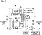
- the electric brake device includes at least an electric motor device Dm, and, in the present embodiment, further includes a brake manipulator 18 ( Fig. 2 ) and a power supply device 3.
- the electric motor device Dm includes an electric actuator 1 and a control device 2. Firstly, the electric actuator 1 will be described.
- the electric actuator 1 includes an electric motor 4, a speed reduction mechanism 5, a friction member manipulator 6, a parking brake mechanism Pb, a brake rotor Br, a friction member 9, and a load sensor Sa ( Fig. 2 ).
- the electric motor 4, the speed reduction mechanism 5, and the friction member manipulator 6 are incorporated in, for example, a housing (not shown) or the like.
- the electric motor 4 is a synchronous electric motor having a stator and a rotor, and is preferably implemented by, for example, a permanent magnet type synchronous electric motor since the electric motor 4 comes to be disposed in a smaller space and generate higher torque.
- a permanent magnet type synchronous electric motor since the electric motor 4 comes to be disposed in a smaller space and generate higher torque.
- the arrangement of the stator and the rotor in the electric motor 4 in the example in Fig. 1 the arrangement of those in a radial-gap-type motor that generates torque by means of interlinkage magnetic flux in the radial direction of a rotational shaft is employed.
- the stator may include stator coils for two or more systems.
- the electric motor 4 may be an axial-gap-type motor that generates torque by means of interlinkage magnetic flux in the direction of the rotational shaft.
- the speed reduction mechanism 5 is a mechanism for reducing the speed of rotation, or the number of rotation per unit time, of the electric motor 4, and includes a primary gear 12, an intermediate (secondary) gear 13, and a tertiary gear 11.
- the speed reduction mechanism 5 can reduce, by means of the intermediate gear 13, the speed of rotation of the primary gear 12 mounted to a rotor shaft 4c of the electric motor 4, and can transmit this reduced rotation to the tertiary gear 11 fixed to an end of a rotational shaft 10.
- the linear motion mechanism serving as the friction member manipulator 6 is a mechanism in which rotary motion outputted from the speed reduction mechanism 5 is converted into linear motion of the linear motion portion 14 by a feed screw mechanism such that the friction member 9 comes into contact with, or is separated from, the brake rotor Br.
- the linear motion portion 14 is supported so as to be prevented from rotating and be movable in an axial direction denoted by an arrow A1.
- the friction member 9 is disposed at an end, on the outboard side, of the linear motion portion 14.
- the electric brake device By rotation of the electric motor 4 being transmitted to the friction member manipulator 6 through the speed reduction mechanism 5, the rotary motion is converted into linear motion and the linear motion is converted into pressing force of the friction member 9, thereby generating braking force.
- the outer side of the vehicle in the vehicle width direction is referred to as outboard side
- the central side of the vehicle in the vehicle width direction is referred to as inboard side.
- an actuator 16 of the parking brake mechanism Pb for example, a linear solenoid is used.
- a lock member 15 is caused to advance by the actuator 16 so as to be fitted in a locking hole (not shown) formed in the intermediate gear 13, so that the lock member 15 and the intermediate gear 13 are locked by each other, thereby preventing the intermediate gear 13 from rotating. Accordingly, the parking brake device Pb enters a parking lock state. By the lock member 15 being disengaged from the locking hole, the intermediate gear 13 is allowed to rotate, whereby the parking brake device Pb enters an unlock state.
- Fig. 2 is a block diagram indicating a schematic configuration of a control system of the electric brake device.
- each wheel is provided with the corresponding control device 2 and the corresponding electric actuator 1.
- the power supply device 3 and a higher-order ECU (Electronic Control Unit) 17 which is a higher-order control unit of each control device 2 are connected to each control device 2.
- the higher-order ECU 17 for example, an electric control unit for controlling the entire vehicle is used.
- the higher-order ECU 17 has a function of performing integrated control on each control device 2.
- the higher-order ECU is referred to also as a "VCU (Vehicle Control Unit)".
- the power supply device 3 supplies power to the electric motor 4 and the control device 2.
- a stator coil of the electric motor 4 is connected to the power supply device 3 via a motor driver 19 of the control device 2.
- the power supply device 3 for example, a battery, a DC/DC converter, a capacitor, or the like may be used, or a battery, a DC/DC converter, a capacitor, or the like may be used in combination.
- power may be supplied from one system to each coil, or independent power supply systems may be formed.
- the higher-order ECU 17 outputs a braking force command value to each control device 2 in accordance with a sensor output that changes in accordance with the manipulation amount of the brake manipulator 18.
- a brake pedal or the like can be used, but another operation tool such as a push-type switch or a joy stick may be used.
- the control device 2 is implemented by: a microcomputer including a processor; a circuit board mounted with various types of electronic components such as a ROM (Read Only Memory) including a program to be executed by the processor, a RAM (Random Access Memory), and a coprocessor; and the like.
- the control device 2 includes an angle-sensorless control function section 20, a current controller 21, the motor driver 19, and a current estimator 22.
- the angle-sensorless control function section 20 includes an electrical angular speed calculation section 23, a calculation electrical angle determination section 24, and a current command section 25.
- the electrical angular speed calculation section 23 calculates a calculation electrical angular speed of the electric motor 4 inside the control device in accordance with the braking force command value given from the higher-order ECU 17 and a braking force estimated value estimated with respect to the load sensor Sa, more specifically, on the basis of a deviation between these values.
- the load sensor Sa functions as a braking force estimator 26 for obtaining the braking force estimated value.
- the control device 2 may include a braking force estimator and the braking force estimator may calculate the braking force estimated value on the basis of a sensor output from the load sensor Sa.
- the load sensor Sa is used for controlling pressing force, as braking force, between the friction member 9 ( Fig. 1 ) and the brake rotor Br ( Fig. 1 ).
- the load sensor Sa for example, a magnetic sensor or a strain sensor that detects displacement, a pressure sensor, or the like can be used.
- a sensor or the like that detects, as braking force, wheel torque or front-rear force of the wheel mounted with the electric brake device, can be used instead of the load sensor Sa.
- the electrical angular speed calculation section 23 may set, as the calculation electrical angular speed, a value calculated by applying a predetermined control gain to the deviation between the braking force command value and the braking force estimated value.
- the calculation electrical angle determination section 24 has a function of converting the calculation electrical angular speed calculated by the electrical angular speed calculation section 23 into a calculation electrical angle by integrating the calculation electrical angular speed.
- an integrator is used as the calculation electrical angle determination section 24, for example.
- the current command section 25 has a function of generating a motor current target value, and includes a current amplitude determination section 25a for determining an amplitude of motor current, and a current phase determination section 25b for determining a phase of the motor current.
- the current amplitude determination section 25a and the current phase determination section 25b are preferably configured to determine, for example, a norm and a phase in a motor current vector converted for an orthogonal coordinate system since the configuration of the current controller 21 can be simplified. However, the sections 25a and 25b may directly determine the amplitude and the phase of three-phase alternating current.
- the current controller 21 performs follow-up control such that a motor current estimated by a current estimator 22 and a motor current obtained from the calculation electrical angle determined by the calculation electrical angle determination section 24 of the angle-sensorless control function section 20 follow the motor current target value generated by the current command section 25 of the angle-sensorless control function section 20.
- this follow-up control for example, feedback control or feedforward control, based on motor characteristics and the like, may be used or the feedback control and the feedforward control may be used in combination.
- the current estimator 22 may be of a non-contact type in which a magnetic field from a motor current transmission line is detected, or may employ a method in which a power transmission line is provided with a shunt resistor or the like and detection is performed based on voltages at both ends thereof.
- the current estimator 22 may be provided to a power transmission line on the secondary side as shown in Fig. 2 , or may be provided to a power transmission line on the primary side and a secondary-side current in the power transmission line on the secondary side may be estimated.
- the current estimator 22 may be employed using a method of performing detection based on voltages or the like at predetermined locations in the motor driver 19. In detection of current, on the basis of detection of currents of two phases and the relationship in which the total sum of currents of three phases equals zero, a current of the remaining one phase may be estimated, or currents of all the three phases may be detected.
- the motor driver 19 is preferably implemented by, for example, a half-bridge circuit that uses a switch element such as an FFT and preferably configured to perform PWM control in which a time period during which voltage is to be applied to the switch element is determined in accordance with a predetermined duty ratio, since the motor driver 19 comes to be inexpensive and have high performance.
- the motor driver 19 may be provided with a transformation circuit or the like and configured to perform PAM control.
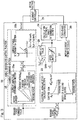
- Fig. 3 is a block diagram indicating a configuration example of the angle-sensorless control function section 20.
- the electrical angular speed calculation section 23 in the present embodiment multiplies a deviation ⁇ F between a braking force command value and a braking force estimated value by a predetermined control gain P ⁇ , thereby deriving a calculation electrical angular speed of the electric motor, i.e., a calculation electrical angular speed calculated inside the control device.
- the control gain P ⁇ is, for example, preferably a nonlinear gain obtained by taking into account influence of the rigidity, of the electric brake device, that becomes nonlinear owing to influence of the friction member 9 ( Fig. 1 ) or the like, but may be a fixed value in order to reduce calculation load.
- the control gain P ⁇ can be determined on the basis of a required control performance by, for example, using a PID controller (Proportional Integral Differential Controller) in which integration and differentiation are used in combination, as necessary.
- PID controller Pro
- the angle-sensorless control function section 20 includes a speed limiter 27 at a stage subsequent to the electrical angular speed calculation section 23.
- the speed limiter 27 restricts the absolute value, of the calculation electrical angular speed derived by the electrical angular speed calculation section 23, to be equal to or smaller than a predetermined value such that the calculation electrical angular speed does not exceed an electrical angular speed at which the electric motor 4 ( Fig. 2 ) can be actually operated.
- the predetermined value is, for example, a value arbitrarily determined from specifications of the electric motor 4 ( Fig. 2 ) or the like, and is determined by, for example, obtaining an appropriate value through one or both of experiment and simulation.
- the current amplitude determination section 25a of the current command section 25 determines, from the braking force command value, a target current norm
- a correlation between the braking force and the current norm is generally one shown in Fig. 3 on the basis of positive efficiency and reverse efficiency that are actuator characteristics ( Fig. 3 ) of the friction member manipulator 6 ( Fig. 2 ) or the like of the electric actuator.
- a desired braking force can be generated if the current norm which is the magnitude of motor current has a value sufficiently exceeding that of a current norm based on the positive efficiency of the actuator characteristics.
- the current norm which is the magnitude of motor current has a value sufficiently exceeding that of a current norm based on the positive efficiency of the actuator characteristics.
- a value that is variable in accordance with the braking force command value is used as the current norm, it is possible to avoid a possibility that great current is kept applied when relatively low braking force is generated or the brake is released.
- Fig. 3 shows an example in which the current amplitude determination section 25a determines a current norm by using the braking force command value.
- a braking force estimated value may be used, or both the braking force command value and the braking force estimated value may be used and the average value between both values or the like may be used.
- the current amplitude determination section 25a may set the current norm to a predetermined lower limit value irrespective of the value based on the braking force.
- the current norm is preferably set to the predetermined lower limit value irrespective of the value based on the braking force since a stable operation can be performed.
- the angle-sensorless control function section 20 shown in Fig. 3 adds a current norm
- is outputted as a value obtained by multiplication, by a predetermined gain P ib , of an absolute value 28.
- the absolute value 28 is outputted as a value obtained, via the speed limiter 27, from the calculation electrical angular speed derived from the electrical angular speed calculation section 23.
- is thus preferably added to the target current norm
- a current norm dependent only on braking force can be used with the gain P ib being set to zero.
- the current phase determination section 25b sets a predetermined current phase ⁇ b , and derives two phase currents i b ⁇ and i b ⁇ which form a current vector based on the target current norm
- the current controller 21 performs follow-up control such that motor currents, outputted as values obtained, via a two-phase converter 29, from the calculation electrical angle determined by the calculation electrical angle determination section 24, follow the two phase currents i b ⁇ and i b ⁇ .
- the current phase determination section 25b sets such a current phase ⁇ b as to satisfy a current condition that, when an electrical angle deviation obtained by subtracting the actual electrical angle of the electric motor 4 ( Fig. 2 ) from the calculation electrical angle determined by the calculation electrical angle determination section 24 is within a predetermined positive or negative range, the relationships in increase and decrease between the electrical angle deviation and the electric motor torque can be the same.
- the current phase ⁇ b is preferably set to be approximate to ⁇ /4 in the calculation electrical angle by the current phase determination section 25b. If the actual electrical angle lags behind the calculation electrical angle by the current phase ⁇ b set by the current phase determination section 25b, the motor torque increases relative to a predetermined current norm. If the actual electrical angle advances from the calculation electrical angle by the current phase ⁇ b , the motor torque decreases relative to a predetermined current norm. As a result, in a situation in which a certain load is applied, the actual electrical angle follows the calculation electrical angle calculated inside the control device, in a state where the actual electrical angle has an electrical angle deviation that corresponds to the load.
- an actual motor electrical angular speed follows the calculation electrical angular speed calculated inside the control device, with substantially no deviation. That is, since the calculation electrical angular speed is determined in accordance with the braking force deviation, the braking force estimated value can be caused to follow the braking force command value, with substantially no deviation.
- the control device 2 obtains a calculation electrical angular speed by multiplying, by the control gain, the deviation between the braking force estimated value and the braking force command value, and obtains a motor current from a calculation electrical angle determined by integration or the like of the calculation electrical angular speed.
- the control device 2 causes the motor current obtained from the calculation electrical angle and the like to follow the motor current target value obtained from the target current norm
- the motor current obtained in accordance with the deviation (braking force deviation) between the braking force estimated value and the braking force command value follows the motor current target value obtained from the current phase not having the braking force deviation and the like. Accordingly, accurate follow-up control of the braking force estimated value relative to the braking force command value can be performed through angle-sensorless control.
- the control device 2 determines a current norm of the electric motor 4 on the basis of one or both of the braking force command value and the braking force estimated value, and controls the motor current of the electric motor 4 on the basis of the current norm and the current phase. Accordingly, the responsiveness and the maximum braking force can be improved, and power consumption can be reduced when no braking manipulation is performed or a relatively gentle braking manipulation is performed.
- Each section in the control device 2 is, specifically, configured from a hardware circuit or a software mathematical function (hereinafter, sometimes referred to as "embodied model") on a processor (not shown) that enables calculation and output of a result thereof, with use of a LUT (Look Up Table) implemented by software or hardware, or a predetermined transform function contained in a library of software, or hardware equivalent thereto, etc., and, as necessary, a comparison function or a four arithmetic operation function in the library, or hardware equivalent thereto, etc.
- a LUT Look Up Table
- a control device 2A in Fig. 4 and Fig. 5 indicates an example in which an angle detector Sb and an ordinary control system using the angle detector Sb are provided to the configuration example in Fig. 2 and which the configuration example in Fig. 2 is used as a redundant system, for the ordinary control system, in case of occurrence of an abnormality in the angle detector Sb.
- Fig. 4 shows connection patterns of switch sections 30 and 31 in a case where the angle detector Sb is normal.
- Fig. 5 shows connection patterns of the switch sections 30 and 31 in a case where the angle-sensorless control function section 20 is used when an abnormality occurs in the angle detector Sb.
- the electric actuator 1 includes the angle detector Sb for directly detecting an angle of the electric motor 4 or a physical amount equivalent to the angle.
- the angle detector Sb for example, an angle sensor such as a resolver or a magnetic encoder is preferably used since such an angle sensor is highly accurate and highly reliable.
- any of various types of sensors such as an optical encoder can also be used.
- the control device 2A includes, in addition to the constituents in the configuration example ( Fig. 2 ) of the aforementioned embodiment, a braking force controller 32, a current converter 33, a responsiveness-restricting function section 34, a control switch 35, and the switch sections 30 and 31.
- the braking force controller 32 performs control calculation such that a braking force command value given from the higher-order ECU 17 is exerted.
- the braking force controller 32 performs, for example, load feedback control in which the braking force command value is converted into an actuator load that is a load of the electric actuator 1 and follow-up control is performed such that a sensor output from the load sensor Sa follows the actuator load. Accordingly, highly-accurate braking force control can be easily performed.
- the braking force controller 32 obtains a motor torque command value required for the braking force control.
- the current converter 33 performs, for example, two-phase conversion on the motor torque command value from the braking force controller 32, thereby converting the motor torque command value into a current command value in orthogonal axes (the d axis and the q axis of an orthogonal coordinate system).
- the current converter 33 may be configured to output the amplitude, the phase, and the like of three-phase alternating current, for example.
- the current controller 21 performs follow-up control such that a motor current estimated by the current estimator 22 follows the current command value from the current converter 33.
- this follow-up control for example, feedback control or feedforward control based on motor characteristics and the like may be used, or the feedback control and the feedforward control may be used in combination.
- the current controller 21 performs, in addition to the follow-up control of the motor current, control such that the motor current comes to have a current phase that is based on a detection result from the angle detector Sb.
- the control switch 35 includes an abnormality determination section 35a for determining whether or not the angle detector Sb is normal, and a control switch section 35b.
- the abnormality determination section 35a may perform, for example: determination, as to abnormality, that uses an abnormality self-diagnosis function of the angle detector Sb or the like; determination, as to abnormality, that is based on comparison with a sensor output from another sensor or the like such as the load sensor Sa; or these determinations combined.
- the control switch section 35b switches the switch sections 30 and 31 to the control system using the angle-sensorless control function section 20.
- the control device 2A in this example includes the responsiveness-restricting function section 34 which performs restriction such that the response speed of the electric brake device is reduced in a case where the angle detector Sb is not normal and control is executed by the angle-sensorless control function section 20, as compared to a case where the angle detector Sb is normal.
- the responsiveness-restricting function section 34 for example, a low-pass filter is used.
- the control system using the angle-sensorless control function section 20 is preferably provided with the responsiveness-restricting function section 34 for the braking force command value so as to restrict the responsiveness.
- Fig. 5 shows an example in which the responsiveness-restricting function section 34 is provided only for a braking force command value that is to be inputted to the angle-sensorless control function section 20.
- the responsiveness may be restricted in the following manner: the responsiveness-restricting function section 34 is provided (not shown) also for a braking force command value that is to be inputted to the braking force controller 32 of the ordinary control system, and time constants that are different from each other are set for the responsiveness-restricting function sections 34, 34 corresponding the angle-sensorless control function section 20 and the braking force controller 32, and specifically, the time constant of the responsiveness-restricting function section 34 for the angle-sensorless control function section 20 is set to be larger than the other.
- Each of the switch sections 30 and 31 is illustrated for convenience of explaining a flow of a signal, and may be implemented by, for example, divergence command of an IF condition or the like in software, and thus are not necessarily to be an actual switch or a function of performing a switch operation.
- the control device may have a function of performing determination as to a brake-released state where no braking force is generated, and may set the motor current to zero when the brake-released state is determined to have been achieved. Whether or not the brake-released state has been achieved, can be determined on the basis of, for example, a sensor output from the load sensor. In this case, the power consumption in the brake-released state can be reduced.
- a conversion mechanism portion of the linear motion mechanism instead of a planetary roller, it is possible to use: various types of screw mechanisms such as a ball screw; a mechanism using the slope of a ball ramp or the like; or the like.
- the electric actuator may have a configuration in which the speed reduction mechanism is not interposed.
Landscapes
- Engineering & Computer Science (AREA)
- Mechanical Engineering (AREA)
- Transportation (AREA)
- Power Engineering (AREA)
- General Engineering & Computer Science (AREA)
- Control Of Electric Motors In General (AREA)
- Regulating Braking Force (AREA)
- Braking Systems And Boosters (AREA)
- Control Of Ac Motors In General (AREA)
- Valves And Accessory Devices For Braking Systems (AREA)
- Control Of Motors That Do Not Use Commutators (AREA)
Abstract
Description
- This application is based on and claims Convention priority to Japanese patent application No.
2016-215885, filed November 4, 2016 - The present invention relates to an electric brake device, specifically, an electric brake device capable of performing angle-sensorless control.
- The following technologies have been proposed for an electric motor device and an electric actuator that uses an electric motor.
- (1) A technology in which rotation drive by an electric motor is reduced in speed by a speed reducer or reduction gear, this rotation drive having been reduced in speed is converted into linear drive via a linear motion mechanism, and a friction pad is brought into pressure contact with a disc rotor by this linear drive, thereby applying braking force (Patent Document 1).
- (2) A sensorless vector control technology using a phase estimation observer for rotor magnetic flux (Patent Document 2).
- (3) A sensorless vector control technology for a synchronous motor, in which a rotor angle is estimated from high frequency voltage and current (Patent Document 3).
- (4) A sensorless vector control technology for an AC motor, in which a rotor angle and a rotor phase are estimated from imperfect-circle high frequency voltage and current, in a γ-δ semi-synchronous coordinate system obtained through two-phase conversion (Patent Document 4).
- (5) A technology related to a sensorless control method, in which a phase difference is automatically adjusted in accordance with load, with a motor current phase being in such a region that torque monotonically increases relative to current phase (Patent Document 5).
-
- [Patent Document 1]
JP Laid-open Patent Publication No. 2003-247576 - [Patent Document 2]
JP Laid-open Patent Publication No. 2004-96979 - [Patent Document 3]
JP Laid-open Patent Publication No. 2002-51597 - [Patent Document 4]
JP Laid-open Patent Publication No. 2008-295279 - [Patent Document 5]
JP Laid-open Patent Publication No. 2006-174681 - For example, in an electric brake device using an electric actuator to which a technology such as one in Patent Document 1 is applied, an electric motor may be required to have very high redundancy. For example, even when an abnormality occurs in a motor coil, a sensor, or the like, an operation may need to be continued. In particular, in a case where a motor angle sensor is used, the motor angle sensor has to be included in the motor in many cases, and thus may be subjected to a very high load.
- As a measure against the above, for example, angle-sensorless control such as ones disclosed in
Patent Documents 2 to 5 may be used. As the angle-sensorless control, for example, a method disclosed inPatent Document 2 has been generally known in which an angle of rotator is estimated from the relationship between voltage and current dependent on induced voltage due to rotor magnetic flux and the like. However, in Patent Document 1, for example, when an operation for obtaining an angular speed of zero to a low speed, such as an operation of performing follow-up with respect to a pedal manipulation or maintaining braking force at a predetermined small value, is performed in an electric brake device, estimation of the angle may become difficult owing to very small induced voltage. In addition, for example, in an ABS (Antilock Brake System) an operation that results, in very great fluctuation in angular speed such as an operation of a brake repeating pressure increase and pressure reduction at high speed. When such operation is continuously performed, an estimation error due to an error in the inductance of a motor or the like does not sufficiently converge, whereby accurate estimation of an angle may become difficult. - As a method for enabling estimation of a motor angle even in the above case, for example, a method disclosed in
Patent Document - As an angle-sensorless control method that does not require any superposition of frequency components as in the above method, for example, a method disclosed in
Patent Document 5 has been proposed in which a two-phase-orthogonal coordinate system is rotated by a vector rotator in a control device, with a current phase being in such a region (MIR region) that torque shows a tendency of monotonically increasing relative to a phase difference. However, in this method, a deviation is generated between the phase of the vector rotator and an actual rotor phase in accordance with a load at the time of positioning in case that a vector becomes stationary. Thus it may become difficult to perform accurate positioning in an electric brake device in which the load fluctuates in accordance with the braking force. - In addition, if the method in
Patent Document 5 is applied to an electric brake device, motor current when positioning is performed such that the braking force comes to have a predetermined value is constantly fixed at the maximum current value. Accordingly, the same degree of motor current as that when great braking force is generated, is applied also at the time of a gentle brake manipulation for moderate braking or an operation of releasing a brake by taking a foot off a brake pedal, resulting in power consumption increase. Furthermore, since such great current can be constantly applied, heat generation of the electric motor increases, whereby the size, the weight, and the cost of the motor may be increased. - An object of the present invention is to provide a brake device that can perform accurate follow-up control of a braking force estimated value relative to a braking force command value through angle-sensorless control, and that enables improvement in redundancy, reduction in cost, and the like.
- Hereinafter, in order to facilitate understanding of the present invention, the present invention will be described with reference to the reference numerals in embodiments for the sake of convenience.
- An electric brake device according to the present invention is an electric brake device including: a brake rotor Br; a
friction member 9 configured to be brought into contact with the brake rotor Br; afriction member manipulator 6 configured to bring thefriction member 9 into contact with the brake rotor Br; anelectric motor 4 configured to drive thefriction member manipulator 6; abraking force estimator 26 configured to obtain a braking force estimated value which is an estimated value of braking force generated when thefriction member 9 is brought into contact with the brake rotor Br by thefriction member manipulator 6; and acontrol device braking force estimator 26 follows a given braking force command value, wherein
thecontrol device control function section 20 configured to determine a phase of phase current of theelectric motor 4 irrespective of an actual angle of theelectric motor 4 and control theelectric motor 4 to have a current value that is based on the determined phase of the phase current, and
the angle-sensorlesscontrol function section 20 includes a currentphase determination section 25b configured to determine a current phase that is the phase of the phase current of theelectric motor 4 on the basis of a deviation between the braking force command value and the braking force estimated value. - In this configuration, the angle-sensorless
control function section 20 of thecontrol device electric motor 4 irrespective of an actual angle of theelectric motor 4, and controls theelectric motor 4 in accordance with a current value (motor current target value) that is based on the determined current phase. The currentphase determination section 25b of the angle-sensorlesscontrol function section 20, for example, determines the current phase on the basis of a deviation between the braking force command value and the braking force estimated value estimated by thebraking force estimator 26. Thecontrol device control device phase determination section 25b and the like. In this manner, the motor current obtained in accordance with the deviation (braking force deviation) between the braking force estimated value and the braking force command value, follows the motor current target value obtained from the current phase not having the braking force deviation and the like. Accordingly, accurate follow-up control of the braking force estimated value relative to the braking force command value can be performed through the angle-sensorless control. In addition, in a case where no angle sensor for directly detecting the angle of theelectric motor 4 is provided, the number of components can be reduced, resulting in reduction in cost. - The angle-sensorless
control function section 20 may include: - an electrical angular
speed calculation section 23 configured to determine a calculation electrical angular speed of theelectric motor 4 on the basis of the deviation between the braking force command value and the braking force estimated value; and - a calculation electrical
angle determination section 24 configured to determine a calculation electrical angle of theelectric motor 4 on the basis of an integral value of the calculation electrical angular speed determined by the electrical angularspeed calculation section 23, and - The calculation electrical angular speed and the calculation electrical angle are the electrical angular speed and the electrical angle calculated inside the control device, respectively.
- The predetermined positive or negative range is a range arbitrarily determined in designing or the like, and is determined by, for example, obtaining an appropriate range through one or both of experiment and simulation.
- In this configuration, the electrical angular
speed calculation section 23 determines the calculation electrical angular speed of theelectric motor 4 on the basis of the deviation between the braking force command value and the braking force estimated value. The calculation electricalangle determination section 24 converts the determined calculation electrical angular speed into a calculation electrical angle through integration or the like of the calculation electrical angular speed. The currentphase determination section 25b controls the motor current to have such a current phase as to satisfy a current condition that, when an electrical angle deviation obtained by subtracting the actual electrical angle from the calculation electrical angle is within the predetermined positive or negative range, the relationships in increase and decrease between the electrical angle deviation and the electric motor torque become the same. - If the actual electrical angle lags behind the calculation electrical angle, the motor torque increases relative to a predetermined current norm. If the actual electrical angle advances from the calculation electrical angle, the motor torque decreases relative to a predetermined current norm. As a result, in a situation in which a certain load is applied, the actual electrical angle follows the calculation electrical angle calculated inside the control device, in a state where the actual electrical angle has an electrical angle deviation that corresponds to the load. In other words, an actual motor electrical angular speed follows the calculation electrical angular speed calculated inside the control device, with substantially no deviation. That is, since the calculation electrical angular speed is determined in accordance with the braking force deviation, the braking force estimated value can be caused to follow the braking force command value, with substantially no deviation.
- The
control device electric motor 4 on the basis of one or both of the braking force command value and the braking force estimated value, and may control the motor current of theelectric motor 4 on the basis of the current phase and the magnitude of the motor current. In this case, the responsiveness and the maximum braking force can be improved, and power consumption can be reduced when no braking manipulation is performed or a relatively gentle braking manipulation is performed. - When a value based on a braking force, which is at least one of the braking force command value and the braking force estimated value, becomes smaller than a predetermined value, the
control device - The
control device - The electric brake device may include an angle detector Sb configured to directly detect an angle of the
electric motor 4 or a physical amount equivalent to the angle, wherein
thecontrol device 2A may include anabnormality determination section 35a configured to determine whether or not the angle detector Sb is normal, and, when determination that the angle detector Sb is normal is made by theabnormality determination section 35a, thecontrol device 2A may control the motor current of theelectric motor 4 to have a current phase that is based on a detection result from the angle detector Sb, whereas, when determination that the angle detector Sb is not normal is made by theabnormality determination section 35a, thecontrol device 2A may control theelectric motor 4 by means of the angle-sensorlesscontrol function section 20. - In this configuration, the responsiveness of an ordinary control system that uses the angle detector Sb can be made higher than that of a control system that uses the angle-sensorless
control function section 20. When it is determined that the angle detector Sb is not normal, theelectric motor 4 is controlled by the angle-sensorlesscontrol function section 20, whereby the redundancy can be improved. - The
control device 2A may include a responsiveness-restrictingfunction section 34 configured to perform restriction such that a response speed of the electric brake device is reduced in a case where the determination that the angle detector Sb is not normal is made and control is executed by the angle-sensorlesscontrol function section 20, as compared to a case where the angle detector Sb is normal. Here, in the case where the control is executed by the angle-sensorlesscontrol function section 20, overshoots or vibrations may occur owing to a steep change in the braking force command value. Therefore, by restricting the responsiveness of the electric brake device when the angle detector Sb is not normal as mentioned above, overshoots and vibrations can be suppressed, whereby the stability of the control system can be enhanced. - Any combination of at least two constructions, disclosed in the appended claims and/or the specification and/or the accompanying drawings should be construed as included within the scope of the present invention. In particular, any combination of two or more of the appended claims should be equally construed as included within the scope of the present invention.
- In any event, the present invention will become more clearly understood from the following description of preferred embodiments thereof, when taken in conjunction with the accompanying drawings. However, the embodiments and the drawings are given only for the purpose of illustration and explanation, and are not to be taken as limiting the scope of the present invention in any way whatsoever, which scope is to be determined by the appended claims. In the accompanying drawings, like reference numerals are used to denote like parts throughout the several views, and:
-
Fig. 1 is a diagram schematically indicating an electric brake device according to one embodiment of the present invention; -
Fig. 2 is a block diagram indicating a schematic configuration of a control system of the electric brake device; -
Fig. 3 is a block diagram indicating a configuration example of an angle-sensorless control function section of the electric brake device; -
Fig. 4 is a block diagram of a control system, in a case where an angle detector is normal, of an electric brake device according to another embodiment of the present invention; and -
Fig. 5 is a block diagram of the control system, in a case where an abnormality occurs in the angle detector, of the electric brake device. - An electric brake device according to one embodiment of the present invention will be described with reference to
Fig. 1 to Fig. 3 . The electric brake device is mounted to, for example, a vehicle. As shown inFig. 1 , the electric brake device includes at least an electric motor device Dm, and, in the present embodiment, further includes a brake manipulator 18 (Fig. 2 ) and apower supply device 3. The electric motor device Dm includes an electric actuator 1 and acontrol device 2. Firstly, the electric actuator 1 will be described. - The electric actuator 1 includes an
electric motor 4, aspeed reduction mechanism 5, afriction member manipulator 6, a parking brake mechanism Pb, a brake rotor Br, afriction member 9, and a load sensor Sa (Fig. 2 ). Theelectric motor 4, thespeed reduction mechanism 5, and thefriction member manipulator 6 are incorporated in, for example, a housing (not shown) or the like. - The
electric motor 4 is a synchronous electric motor having a stator and a rotor, and is preferably implemented by, for example, a permanent magnet type synchronous electric motor since theelectric motor 4 comes to be disposed in a smaller space and generate higher torque. As the arrangement of the stator and the rotor in theelectric motor 4 in the example inFig. 1 , the arrangement of those in a radial-gap-type motor that generates torque by means of interlinkage magnetic flux in the radial direction of a rotational shaft is employed. It is noted that the stator may include stator coils for two or more systems. Alternatively, theelectric motor 4 may be an axial-gap-type motor that generates torque by means of interlinkage magnetic flux in the direction of the rotational shaft. - The
speed reduction mechanism 5 is a mechanism for reducing the speed of rotation, or the number of rotation per unit time, of theelectric motor 4, and includes aprimary gear 12, an intermediate (secondary)gear 13, and atertiary gear 11. In this example, thespeed reduction mechanism 5 can reduce, by means of theintermediate gear 13, the speed of rotation of theprimary gear 12 mounted to arotor shaft 4c of theelectric motor 4, and can transmit this reduced rotation to thetertiary gear 11 fixed to an end of arotational shaft 10. - As the
friction member manipulator 6, a linear motion mechanism is used. The linear motion mechanism serving as thefriction member manipulator 6 is a mechanism in which rotary motion outputted from thespeed reduction mechanism 5 is converted into linear motion of thelinear motion portion 14 by a feed screw mechanism such that thefriction member 9 comes into contact with, or is separated from, the brake rotor Br. Thelinear motion portion 14 is supported so as to be prevented from rotating and be movable in an axial direction denoted by an arrow A1. Thefriction member 9 is disposed at an end, on the outboard side, of thelinear motion portion 14. By rotation of theelectric motor 4 being transmitted to thefriction member manipulator 6 through thespeed reduction mechanism 5, the rotary motion is converted into linear motion and the linear motion is converted into pressing force of thefriction member 9, thereby generating braking force. In a state where the electric brake device is mounted to a vehicle, the outer side of the vehicle in the vehicle width direction is referred to as outboard side, and the central side of the vehicle in the vehicle width direction is referred to as inboard side. - As an
actuator 16 of the parking brake mechanism Pb, for example, a linear solenoid is used. Alock member 15 is caused to advance by theactuator 16 so as to be fitted in a locking hole (not shown) formed in theintermediate gear 13, so that thelock member 15 and theintermediate gear 13 are locked by each other, thereby preventing theintermediate gear 13 from rotating. Accordingly, the parking brake device Pb enters a parking lock state. By thelock member 15 being disengaged from the locking hole, theintermediate gear 13 is allowed to rotate, whereby the parking brake device Pb enters an unlock state. - The
control device 2 and thepower supply device 3 are connected to the electric actuator 1.Fig. 2 is a block diagram indicating a schematic configuration of a control system of the electric brake device. For example, each wheel is provided with thecorresponding control device 2 and the corresponding electric actuator 1. Thepower supply device 3 and a higher-order ECU (Electronic Control Unit) 17 which is a higher-order control unit of eachcontrol device 2 are connected to eachcontrol device 2. As the higher-order ECU 17, for example, an electric control unit for controlling the entire vehicle is used. The higher-order ECU 17 has a function of performing integrated control on eachcontrol device 2. The higher-order ECU is referred to also as a "VCU (Vehicle Control Unit)". - The
power supply device 3 supplies power to theelectric motor 4 and thecontrol device 2. A stator coil of theelectric motor 4 is connected to thepower supply device 3 via amotor driver 19 of thecontrol device 2. As thepower supply device 3, for example, a battery, a DC/DC converter, a capacitor, or the like may be used, or a battery, a DC/DC converter, a capacitor, or the like may be used in combination. In a case where stator coils for two or more systems are used, power may be supplied from one system to each coil, or independent power supply systems may be formed. - The higher-
order ECU 17 outputs a braking force command value to eachcontrol device 2 in accordance with a sensor output that changes in accordance with the manipulation amount of thebrake manipulator 18. As thebrake manipulator 18, for example, a brake pedal or the like can be used, but another operation tool such as a push-type switch or a joy stick may be used. - The
control device 2 is implemented by: a microcomputer including a processor; a circuit board mounted with various types of electronic components such as a ROM (Read Only Memory) including a program to be executed by the processor, a RAM (Random Access Memory), and a coprocessor; and the like. Thecontrol device 2 includes an angle-sensorlesscontrol function section 20, acurrent controller 21, themotor driver 19, and acurrent estimator 22. The angle-sensorlesscontrol function section 20 includes an electrical angularspeed calculation section 23, a calculation electricalangle determination section 24, and acurrent command section 25. - The electrical angular
speed calculation section 23 calculates a calculation electrical angular speed of theelectric motor 4 inside the control device in accordance with the braking force command value given from the higher-order ECU 17 and a braking force estimated value estimated with respect to the load sensor Sa, more specifically, on the basis of a deviation between these values. In this example, the load sensor Sa functions as a brakingforce estimator 26 for obtaining the braking force estimated value. However, as another example, thecontrol device 2 may include a braking force estimator and the braking force estimator may calculate the braking force estimated value on the basis of a sensor output from the load sensor Sa. - The load sensor Sa is used for controlling pressing force, as braking force, between the friction member 9 (
Fig. 1 ) and the brake rotor Br (Fig. 1 ). As the load sensor Sa, for example, a magnetic sensor or a strain sensor that detects displacement, a pressure sensor, or the like can be used. Alternatively, a sensor or the like that detects, as braking force, wheel torque or front-rear force of the wheel mounted with the electric brake device, can be used instead of the load sensor Sa. - The electrical angular
speed calculation section 23 may set, as the calculation electrical angular speed, a value calculated by applying a predetermined control gain to the deviation between the braking force command value and the braking force estimated value. The calculation electricalangle determination section 24 has a function of converting the calculation electrical angular speed calculated by the electrical angularspeed calculation section 23 into a calculation electrical angle by integrating the calculation electrical angular speed. As the calculation electricalangle determination section 24, for example, an integrator is used. - The
current command section 25 has a function of generating a motor current target value, and includes a currentamplitude determination section 25a for determining an amplitude of motor current, and a currentphase determination section 25b for determining a phase of the motor current. The currentamplitude determination section 25a and the currentphase determination section 25b are preferably configured to determine, for example, a norm and a phase in a motor current vector converted for an orthogonal coordinate system since the configuration of thecurrent controller 21 can be simplified. However, thesections - The
current controller 21 performs follow-up control such that a motor current estimated by acurrent estimator 22 and a motor current obtained from the calculation electrical angle determined by the calculation electricalangle determination section 24 of the angle-sensorlesscontrol function section 20 follow the motor current target value generated by thecurrent command section 25 of the angle-sensorlesscontrol function section 20. As this follow-up control, for example, feedback control or feedforward control, based on motor characteristics and the like, may be used or the feedback control and the feedforward control may be used in combination. - The
current estimator 22 may be of a non-contact type in which a magnetic field from a motor current transmission line is detected, or may employ a method in which a power transmission line is provided with a shunt resistor or the like and detection is performed based on voltages at both ends thereof. In this case, thecurrent estimator 22 may be provided to a power transmission line on the secondary side as shown inFig. 2 , or may be provided to a power transmission line on the primary side and a secondary-side current in the power transmission line on the secondary side may be estimated. Alternatively, thecurrent estimator 22 may be employed using a method of performing detection based on voltages or the like at predetermined locations in themotor driver 19. In detection of current, on the basis of detection of currents of two phases and the relationship in which the total sum of currents of three phases equals zero, a current of the remaining one phase may be estimated, or currents of all the three phases may be detected. - The
motor driver 19 is preferably implemented by, for example, a half-bridge circuit that uses a switch element such as an FFT and preferably configured to perform PWM control in which a time period during which voltage is to be applied to the switch element is determined in accordance with a predetermined duty ratio, since themotor driver 19 comes to be inexpensive and have high performance. Alternatively, themotor driver 19 may be provided with a transformation circuit or the like and configured to perform PAM control. - It is noted besides the above that the functional blocks in
Fig. 2 are given merely for convenience of explaining functions. Thus, in implementation of the functional blocks, the manner of division into functions are not necessarily to be the same as that inFig. 2 , and, as necessary, a plurality of the blocks may be unified or one block may be implemented as functions obtained by further dividing the one block. In addition, other sensors (not shown) such as a thermistor, a redundant system (not shown), and the like are appropriately provided as necessary. -
Fig. 3 is a block diagram indicating a configuration example of the angle-sensorlesscontrol function section 20. The electrical angularspeed calculation section 23 in the present embodiment multiplies a deviation ΔF between a braking force command value and a braking force estimated value by a predetermined control gain Pω, thereby deriving a calculation electrical angular speed of the electric motor, i.e., a calculation electrical angular speed calculated inside the control device. The control gain Pω is, for example, preferably a nonlinear gain obtained by taking into account influence of the rigidity, of the electric brake device, that becomes nonlinear owing to influence of the friction member 9 (Fig. 1 ) or the like, but may be a fixed value in order to reduce calculation load. Alternatively, the control gain Pω can be determined on the basis of a required control performance by, for example, using a PID controller (Proportional Integral Differential Controller) in which integration and differentiation are used in combination, as necessary. - The angle-sensorless
control function section 20 includes aspeed limiter 27 at a stage subsequent to the electrical angularspeed calculation section 23. Thespeed limiter 27 restricts the absolute value, of the calculation electrical angular speed derived by the electrical angularspeed calculation section 23, to be equal to or smaller than a predetermined value such that the calculation electrical angular speed does not exceed an electrical angular speed at which the electric motor 4 (Fig. 2 ) can be actually operated. The predetermined value is, for example, a value arbitrarily determined from specifications of the electric motor 4 (Fig. 2 ) or the like, and is determined by, for example, obtaining an appropriate value through one or both of experiment and simulation. - The current
amplitude determination section 25a of thecurrent command section 25 determines, from the braking force command value, a target current norm |ib1| which is a current norm in a motor current vector converted for an orthogonal coordinate system. When the phase of a motor current is controlled to be a desired current phase, a correlation between the braking force and the current norm is generally one shown inFig. 3 on the basis of positive efficiency and reverse efficiency that are actuator characteristics (Fig. 3 ) of the friction member manipulator 6 (Fig. 2 ) or the like of the electric actuator. - Therefore, a desired braking force can be generated if the current norm which is the magnitude of motor current has a value sufficiently exceeding that of a current norm based on the positive efficiency of the actuator characteristics. In addition, if a value that is variable in accordance with the braking force command value is used as the current norm, it is possible to avoid a possibility that great current is kept applied when relatively low braking force is generated or the brake is released.
-
Fig. 3 shows an example in which the currentamplitude determination section 25a determines a current norm by using the braking force command value. However, instead of the braking force command value, a braking force estimated value may be used, or both the braking force command value and the braking force estimated value may be used and the average value between both values or the like may be used. In addition, when a value based on a braking force, which is at least one of the braking force command value and the braking force estimated value, becomes smaller than a predetermined value, the currentamplitude determination section 25a may set the current norm to a predetermined lower limit value irrespective of the value based on the braking force. In a region in which influences of cogging torque, actuator frictional force, and the like are relatively great and the braking force is low, the current norm is preferably set to the predetermined lower limit value irrespective of the value based on the braking force since a stable operation can be performed. - The angle-sensorless
control function section 20 shown inFig. 3 adds a current norm |ib2| to the target current norm |ib1| determined by the currentamplitude determination section 25a, thereby deriving a final target current norm |ib|. The current norm |ib2| is outputted as a value obtained by multiplication, by a predetermined gain Pib, of anabsolute value 28. Theabsolute value 28 is outputted as a value obtained, via thespeed limiter 27, from the calculation electrical angular speed derived from the electrical angularspeed calculation section 23. The current norm |ib2| is thus preferably added to the target current norm |ib1| determined by the currentamplitude determination section 25a, since the motor current increases when steep brake response is needed even in a region in which the braking force command value is small, for example, whereby the responsiveness can be improved. However, a current norm dependent only on braking force can be used with the gain Pib being set to zero. - The current
phase determination section 25b sets a predetermined current phase θb, and derives two phase currents ibγ and ibδ which form a current vector based on the target current norm |ib| and the current phase θb. Thecurrent controller 21 performs follow-up control such that motor currents, outputted as values obtained, via a two-phase converter 29, from the calculation electrical angle determined by the calculation electricalangle determination section 24, follow the two phase currents ibγ and ibδ. The currentphase determination section 25b sets such a current phase θb as to satisfy a current condition that, when an electrical angle deviation obtained by subtracting the actual electrical angle of the electric motor 4 (Fig. 2 ) from the calculation electrical angle determined by the calculation electricalangle determination section 24 is within a predetermined positive or negative range, the relationships in increase and decrease between the electrical angle deviation and the electric motor torque can be the same. - The current phase θb is preferably set to be approximate to π/4 in the calculation electrical angle by the current
phase determination section 25b. If the actual electrical angle lags behind the calculation electrical angle by the current phase θb set by the currentphase determination section 25b, the motor torque increases relative to a predetermined current norm. If the actual electrical angle advances from the calculation electrical angle by the current phase θb, the motor torque decreases relative to a predetermined current norm. As a result, in a situation in which a certain load is applied, the actual electrical angle follows the calculation electrical angle calculated inside the control device, in a state where the actual electrical angle has an electrical angle deviation that corresponds to the load. In other words, an actual motor electrical angular speed follows the calculation electrical angular speed calculated inside the control device, with substantially no deviation. That is, since the calculation electrical angular speed is determined in accordance with the braking force deviation, the braking force estimated value can be caused to follow the braking force command value, with substantially no deviation. - In the electric brake device described above, the
control device 2 obtains a calculation electrical angular speed by multiplying, by the control gain, the deviation between the braking force estimated value and the braking force command value, and obtains a motor current from a calculation electrical angle determined by integration or the like of the calculation electrical angular speed. Thecontrol device 2 causes the motor current obtained from the calculation electrical angle and the like to follow the motor current target value obtained from the target current norm |ib| determined by the currentamplitude determination section 25a and the like and from the current phase θb determined by the currentphase determination section 25b. In this manner, the motor current obtained in accordance with the deviation (braking force deviation) between the braking force estimated value and the braking force command value, follows the motor current target value obtained from the current phase not having the braking force deviation and the like. Accordingly, accurate follow-up control of the braking force estimated value relative to the braking force command value can be performed through angle-sensorless control. - The
control device 2 determines a current norm of theelectric motor 4 on the basis of one or both of the braking force command value and the braking force estimated value, and controls the motor current of theelectric motor 4 on the basis of the current norm and the current phase. Accordingly, the responsiveness and the maximum braking force can be improved, and power consumption can be reduced when no braking manipulation is performed or a relatively gentle braking manipulation is performed. - Each section in the
control device 2 is, specifically, configured from a hardware circuit or a software mathematical function (hereinafter, sometimes referred to as "embodied model") on a processor (not shown) that enables calculation and output of a result thereof, with use of a LUT (Look Up Table) implemented by software or hardware, or a predetermined transform function contained in a library of software, or hardware equivalent thereto, etc., and, as necessary, a comparison function or a four arithmetic operation function in the library, or hardware equivalent thereto, etc. - Another embodiment will be described. In the following description, parts corresponding to the matters described in the preceding embodiment are denoted by the same reference numerals, and the redundant description thereof is omitted. When only a part of a configuration is described, the remaining part of the configuration is the same as that described in the preceding embodiment, unless otherwise specified. The same advantageous effects are achieved by the same configuration. A combination of parts that are specifically described in the embodiments can be implemented, and, further, the embodiments may be partially combined unless such combination causes any problem.
- A
control device 2A inFig. 4 andFig. 5 indicates an example in which an angle detector Sb and an ordinary control system using the angle detector Sb are provided to the configuration example inFig. 2 and which the configuration example inFig. 2 is used as a redundant system, for the ordinary control system, in case of occurrence of an abnormality in the angle detector Sb. -
Fig. 4 shows connection patterns ofswitch sections Fig. 5 shows connection patterns of theswitch sections control function section 20 is used when an abnormality occurs in the angle detector Sb. - As shown in
Fig. 4 andFig. 5 , the electric actuator 1 includes the angle detector Sb for directly detecting an angle of theelectric motor 4 or a physical amount equivalent to the angle. As the angle detector Sb, for example, an angle sensor such as a resolver or a magnetic encoder is preferably used since such an angle sensor is highly accurate and highly reliable. However, any of various types of sensors such as an optical encoder can also be used. - The
control device 2A includes, in addition to the constituents in the configuration example (Fig. 2 ) of the aforementioned embodiment, abraking force controller 32, acurrent converter 33, a responsiveness-restrictingfunction section 34, acontrol switch 35, and theswitch sections braking force controller 32 performs control calculation such that a braking force command value given from the higher-order ECU 17 is exerted. Specifically, as shown inFig. 4 , in a case where the angle detector Sb is normal, thebraking force controller 32 performs, for example, load feedback control in which the braking force command value is converted into an actuator load that is a load of the electric actuator 1 and follow-up control is performed such that a sensor output from the load sensor Sa follows the actuator load. Accordingly, highly-accurate braking force control can be easily performed. Thebraking force controller 32 obtains a motor torque command value required for the braking force control. - The
current converter 33 performs, for example, two-phase conversion on the motor torque command value from thebraking force controller 32, thereby converting the motor torque command value into a current command value in orthogonal axes (the d axis and the q axis of an orthogonal coordinate system). Alternatively, thecurrent converter 33 may be configured to output the amplitude, the phase, and the like of three-phase alternating current, for example. - The
current controller 21 performs follow-up control such that a motor current estimated by thecurrent estimator 22 follows the current command value from thecurrent converter 33. As this follow-up control, for example, feedback control or feedforward control based on motor characteristics and the like may be used, or the feedback control and the feedforward control may be used in combination. Thecurrent controller 21 performs, in addition to the follow-up control of the motor current, control such that the motor current comes to have a current phase that is based on a detection result from the angle detector Sb. - As shown in
Fig. 5 , thecontrol switch 35 includes anabnormality determination section 35a for determining whether or not the angle detector Sb is normal, and acontrol switch section 35b. Theabnormality determination section 35a may perform, for example: determination, as to abnormality, that uses an abnormality self-diagnosis function of the angle detector Sb or the like; determination, as to abnormality, that is based on comparison with a sensor output from another sensor or the like such as the load sensor Sa; or these determinations combined. When theabnormality determination section 35a determines that the angle detector Sb is not normal (i.e., is abnormal), thecontrol switch section 35b switches theswitch sections control function section 20. - In a case where the angle-sensorless
control function section 20 is used, control performance becomes lower than that of the ordinary control system (Fig. 4 ) using the angle detector Sb. Therefore, as shown inFig. 5 , thecontrol device 2A in this example includes the responsiveness-restrictingfunction section 34 which performs restriction such that the response speed of the electric brake device is reduced in a case where the angle detector Sb is not normal and control is executed by the angle-sensorlesscontrol function section 20, as compared to a case where the angle detector Sb is normal. As the responsiveness-restrictingfunction section 34, for example, a low-pass filter is used. - Here, in the case where the control is executed by the angle-sensorless
control function section 20, overshoots or vibrations may occur owing to generation of a relatively great deviation between the calculation electrical angle and the actual electrical angle due to a steep change in the braking force command value. Therefore, by the responsiveness-restrictingfunction section 34 restricting the responsiveness of the electric brake device when the angle detector Sb is not normal as mentioned above, overshoots and vibrations can be suppressed, whereby the stability of the control system can be enhanced. Thus, the control system using the angle-sensorlesscontrol function section 20 is preferably provided with the responsiveness-restrictingfunction section 34 for the braking force command value so as to restrict the responsiveness. -
Fig. 5 shows an example in which the responsiveness-restrictingfunction section 34 is provided only for a braking force command value that is to be inputted to the angle-sensorlesscontrol function section 20. However, the responsiveness may be restricted in the following manner: the responsiveness-restrictingfunction section 34 is provided (not shown) also for a braking force command value that is to be inputted to thebraking force controller 32 of the ordinary control system, and time constants that are different from each other are set for the responsiveness-restrictingfunction sections control function section 20 and thebraking force controller 32, and specifically, the time constant of the responsiveness-restrictingfunction section 34 for the angle-sensorlesscontrol function section 20 is set to be larger than the other. - Each of the
switch sections - The control device may have a function of performing determination as to a brake-released state where no braking force is generated, and may set the motor current to zero when the brake-released state is determined to have been achieved. Whether or not the brake-released state has been achieved, can be determined on the basis of, for example, a sensor output from the load sensor. In this case, the power consumption in the brake-released state can be reduced. As a conversion mechanism portion of the linear motion mechanism, instead of a planetary roller, it is possible to use: various types of screw mechanisms such as a ball screw; a mechanism using the slope of a ball ramp or the like; or the like. The electric actuator may have a configuration in which the speed reduction mechanism is not interposed.
- Although the present invention has been fully described in connection with the preferred embodiments thereof with reference to the accompanying drawings, numerous additions, changes, or deletions can be made without departing from the gist of the present invention. Therefore, such additions, changes, and deletions are also construed as included within the scope of the present invention.
-
- 2, 2A
- control device
- 4
- electric motor
- 6
- friction member manipulator
- 9
- friction member
- 20
- angle-sensorless control function section
- 23
- electrical angular speed calculation section
- 24
- calculation electrical angle determination section
- 25b
- current phase determination section
- 26
- braking force estimator
- 34
- responsiveness-restricting function section
- 35a
- abnormality determination section
- Br
- brake rotor
- Sa
- load sensor
- Sb
- angle detector
Claims (7)
- An electric brake device comprising:a brake rotor;a friction member configured to be brought into contact with the brake rotor;a friction member manipulator configured to bring the friction member into contact with the brake rotor;an electric motor configured to drive the friction member manipulator;a braking force estimator configured to obtain a braking force estimated value which is an estimated value of braking force generated when the friction member is brought into contact with the brake rotor by the friction member manipulator; anda control device configured to perform follow-up control such that the braking force estimated value estimated by the braking force estimator follows a given braking force command value, whereinthe control device includes an angle-sensorless control function section configured to determine a phase of phase current of the electric motor irrespective of an actual angle of the electric motor and control the electric motor to have a current value that is based on the determined phase of the phase current, andthe angle-sensorless control function section includes a current phase determination section configured to determine a current phase that is the phase of the phase current of the electric motor on the basis of a deviation between the braking force command value and the braking force estimated value.
- The electric brake device as claimed in claim 1, wherein
the angle-sensorless control function section includes:an electrical angular speed calculation section configured to determine a calculation electrical angular speed of the electric motor on the basis of the deviation between the braking force command value and the braking force estimated value; anda calculation electrical angle determination section configured to determine a calculation electrical angle of the electric motor on the basis of an integral value of the calculation electrical angular speed determined by the electrical angular speed calculation section, andthe current phase determination section controls motor current of the electric motor to have such a current phase as to satisfy a current condition that, when an electrical angle deviation obtained by subtracting an actual electrical angle of the electric motor from the calculation electrical angle determined by the calculation electrical angle determination section is within a predetermined positive or negative range, relationships in increase and decrease between the electrical angle deviation and electric motor torque become the same. - The electric brake device as claimed in claim 1 or 2, wherein
the control device
has a function of determining a magnitude of the motor current of the electric motor on the basis of one or both of the braking force command value and the braking force estimated value, and
controls the motor current of the electric motor on the basis of the current phase and the magnitude of the motor current. - The electric brake device as claimed in claim 3, wherein,
when a value based on a braking force, which is at least one of the braking force command value and the braking force estimated value, becomes smaller than a predetermined value, the control device sets the magnitude of the motor current to a predetermined lower limit value irrespective of the value based on the braking force. - The electric brake device as claimed in claim 3 or 4, wherein
the control device
has a function of performing determination as to a brake-released state where the braking force is not generated, and
sets the motor current to zero when the brake-released state is determined to have been achieved. - The electric brake device as claimed in any one of claims 1 to 5, the electric brake device further comprising an angle detector configured to directly detect an angle of the electric motor or a physical amount equivalent to the angle, wherein
the control device includes an abnormality determination section configured to determine whether or not the angle detector is normal, and,
when determination that the angle detector is normal is made by the abnormality determination section, the control device controls the motor current of the electric motor to have a current phase that is based on a detection result from the angle detector, whereas, when determination that the angle detector is not normal is made by the abnormality determination section, the control device controls the electric motor by means of the angle-sensorless control function section. - The electric brake device as claimed in claim 6, wherein
the control device includes a responsiveness-restricting function section configured to perform restriction such that a response speed of the electric brake device is reduced in a case where the determination that the angle detector is not normal is made and control is executed by the angle-sensorless control function section, as compared to a case where the angle detector is normal.
Applications Claiming Priority (2)
| Application Number | Priority Date | Filing Date | Title |
|---|---|---|---|
| JP2016215885A JP2018070083A (en) | 2016-11-04 | 2016-11-04 | Electric brake device |
| PCT/JP2017/039689 WO2018084233A1 (en) | 2016-11-04 | 2017-11-02 | Electric brake device |
Publications (3)
| Publication Number | Publication Date |
|---|---|
| EP3536571A1 true EP3536571A1 (en) | 2019-09-11 |
| EP3536571A4 EP3536571A4 (en) | 2020-06-17 |
| EP3536571B1 EP3536571B1 (en) | 2021-08-25 |
Family
ID=62075968
Family Applications (1)
| Application Number | Title | Priority Date | Filing Date |
|---|---|---|---|
| EP17867557.5A Active EP3536571B1 (en) | 2016-11-04 | 2017-11-02 | Electric brake device |
Country Status (5)
| Country | Link |
|---|---|
| US (1) | US10654455B2 (en) |
| EP (1) | EP3536571B1 (en) |
| JP (1) | JP2018070083A (en) |
| CN (1) | CN109890673B (en) |
| WO (1) | WO2018084233A1 (en) |
Families Citing this family (9)
| Publication number | Priority date | Publication date | Assignee | Title |
|---|---|---|---|---|
| CN110550012B (en) * | 2018-05-31 | 2021-10-22 | 比亚迪股份有限公司 | Brake motor control method, device, storage medium and vehicle |
| WO2020008924A1 (en) * | 2018-07-06 | 2020-01-09 | パナソニックIpマネジメント株式会社 | Motor device, controller, motor system, fan unit, and communication method |
| FR3095792B1 (en) * | 2019-05-06 | 2021-04-16 | Safran Landing Systems | Method of controlling an electric braking system and an aircraft electric braking system |
| CN110758369A (en) * | 2019-11-08 | 2020-02-07 | 广州赛特智能科技有限公司 | Unmanned brake system and safety detection method thereof |
| CN111049459B (en) * | 2019-12-31 | 2021-07-20 | 哈尔滨工业大学 | A braking method for a permanent magnet synchronous motor air conditioner drive device without electrolytic capacitors |
| CN113740601B (en) * | 2021-09-27 | 2023-10-20 | 佛山市顺德区美的电子科技有限公司 | Phase current acquisition method, device, equipment, system and storage medium |
| DE102022123082A1 (en) * | 2022-09-12 | 2024-03-14 | Knorr-Bremse Systeme für Schienenfahrzeuge GmbH | Angle of rotation detection system for detecting the angle of rotation of a rotary brake drive for a rail vehicle |
| KR20240145214A (en) * | 2023-03-27 | 2024-10-07 | 에이치엘만도 주식회사 | Motor control apparatus of brake system and control method thereof |
| JP7829543B2 (en) * | 2023-12-22 | 2026-03-13 | 株式会社安川電機 | Robot system and control method |
Family Cites Families (17)
| Publication number | Priority date | Publication date | Assignee | Title |
|---|---|---|---|---|
| JP4560698B2 (en) | 2000-08-03 | 2010-10-13 | 有限会社シー・アンド・エス国際研究所 | Vector control method for synchronous motor |
| JP3750933B2 (en) | 2002-02-22 | 2006-03-01 | 日信工業株式会社 | Electric disc brake layout |
| JP3653670B2 (en) | 2002-08-31 | 2005-06-02 | 有限会社シー・アンド・エス国際研究所 | Vector control method and apparatus for synchronous motor |
| JP3814826B2 (en) | 2004-12-10 | 2006-08-30 | 有限会社シー・アンド・エス国際研究所 | Vector control method for synchronous motor |
| JP2007230318A (en) * | 2006-02-28 | 2007-09-13 | Hitachi Ltd | Electric brake system |
| JP5176406B2 (en) | 2007-05-24 | 2013-04-03 | 日本電産株式会社 | Rotor phase speed estimation device for AC motor |
| WO2013002251A1 (en) * | 2011-06-30 | 2013-01-03 | Ntn株式会社 | Motor drive device |
| JP5845889B2 (en) * | 2011-12-27 | 2016-01-20 | 株式会社アドヴィックス | Brake control device for vehicle |
| JP6080682B2 (en) * | 2013-05-17 | 2017-02-15 | Ntn株式会社 | Electric linear actuator and electric brake device |
| JP6275979B2 (en) * | 2013-09-09 | 2018-02-07 | Ntn株式会社 | Electric brake device |
| CN104442412B (en) * | 2013-09-18 | 2018-01-19 | 通用电气公司 | Device, mobile transporting equipment, electric tractor, electri forklift and associated method |
| JP6430186B2 (en) * | 2014-09-12 | 2018-11-28 | Ntn株式会社 | Electric brake device |
| JP6298390B2 (en) * | 2014-09-29 | 2018-03-20 | 日立オートモティブシステムズ株式会社 | Electric motor drive control device, electric power steering device, electric brake device, electric pump device |
| JP6314800B2 (en) * | 2014-11-14 | 2018-04-25 | トヨタ自動車株式会社 | Braking force control system, vehicle, and braking force control method |
| DE102015211468A1 (en) * | 2015-06-22 | 2016-12-22 | Robert Bosch Gmbh | Method for determining the travel in an electromechanical brake device |
| JP6644502B2 (en) * | 2015-09-10 | 2020-02-12 | Ntn株式会社 | Electric brake device |
| JP2017123726A (en) * | 2016-01-07 | 2017-07-13 | Ntn株式会社 | Electric motor device |
-
2016
- 2016-11-04 JP JP2016215885A patent/JP2018070083A/en active Pending
-
2017
- 2017-11-02 CN CN201780067285.2A patent/CN109890673B/en active Active
- 2017-11-02 WO PCT/JP2017/039689 patent/WO2018084233A1/en not_active Ceased
- 2017-11-02 EP EP17867557.5A patent/EP3536571B1/en active Active
-
2019
- 2019-04-30 US US16/399,334 patent/US10654455B2/en active Active
Also Published As
| Publication number | Publication date |
|---|---|
| US20190256062A1 (en) | 2019-08-22 |
| EP3536571B1 (en) | 2021-08-25 |
| EP3536571A4 (en) | 2020-06-17 |
| CN109890673A (en) | 2019-06-14 |
| CN109890673B (en) | 2021-07-20 |
| JP2018070083A (en) | 2018-05-10 |
| WO2018084233A1 (en) | 2018-05-11 |
| US10654455B2 (en) | 2020-05-19 |
Similar Documents
| Publication | Publication Date | Title |
|---|---|---|
| US10654455B2 (en) | Electric brake device | |
| EP3118076B1 (en) | Electromechanical braking systems and methods with power demand control | |
| US10479341B2 (en) | Electrically powered brake device | |
| US10427661B2 (en) | Electric brake device | |
| EP3521115B1 (en) | Electric brake device | |
| US11060576B2 (en) | Electric linear motion actuator | |
| CN103650327B (en) | Motor drive | |
| US10377355B2 (en) | Electric brake device | |
| US11441626B2 (en) | Electric linear actuator and electric brake device | |
| JP7089868B2 (en) | Electric motor device and electric brake device | |
| US11001246B2 (en) | Electric brake device | |
| JP6732621B2 (en) | Electric motor device and electric brake device | |
| WO2018052068A1 (en) | Electric brake apparatus | |
| WO2019049971A1 (en) | Electric actuator and electric motor device | |
| JP2020043665A (en) | Electric actuator and electric brake device |
Legal Events
| Date | Code | Title | Description |
|---|---|---|---|
| STAA | Information on the status of an ep patent application or granted ep patent |
Free format text: STATUS: THE INTERNATIONAL PUBLICATION HAS BEEN MADE |
|
| PUAI | Public reference made under article 153(3) epc to a published international application that has entered the european phase |
Free format text: ORIGINAL CODE: 0009012 |
|
| STAA | Information on the status of an ep patent application or granted ep patent |
Free format text: STATUS: REQUEST FOR EXAMINATION WAS MADE |
|
| 17P | Request for examination filed |
Effective date: 20190523 |
|
| AK | Designated contracting states |
Kind code of ref document: A1 Designated state(s): AL AT BE BG CH CY CZ DE DK EE ES FI FR GB GR HR HU IE IS IT LI LT LU LV MC MK MT NL NO PL PT RO RS SE SI SK SM TR |
|
| AX | Request for extension of the european patent |
Extension state: BA ME |
|
| DAV | Request for validation of the european patent (deleted) | ||
| DAX | Request for extension of the european patent (deleted) | ||
| A4 | Supplementary search report drawn up and despatched |
Effective date: 20200514 |
|
| RIC1 | Information provided on ipc code assigned before grant |
Ipc: B60T 8/00 20060101ALI20200508BHEP Ipc: B60T 17/18 20060101ALI20200508BHEP Ipc: H02P 21/26 20160101ALI20200508BHEP Ipc: B60T 13/74 20060101AFI20200508BHEP Ipc: H02P 29/028 20160101ALI20200508BHEP Ipc: H02P 6/18 20160101ALI20200508BHEP |
|
| GRAP | Despatch of communication of intention to grant a patent |
Free format text: ORIGINAL CODE: EPIDOSNIGR1 |
|
| STAA | Information on the status of an ep patent application or granted ep patent |
Free format text: STATUS: GRANT OF PATENT IS INTENDED |
|
| INTG | Intention to grant announced |
Effective date: 20210326 |
|
| GRAS | Grant fee paid |
Free format text: ORIGINAL CODE: EPIDOSNIGR3 |
|
| GRAA | (expected) grant |
Free format text: ORIGINAL CODE: 0009210 |
|
| STAA | Information on the status of an ep patent application or granted ep patent |
Free format text: STATUS: THE PATENT HAS BEEN GRANTED |
|
| AK | Designated contracting states |
Kind code of ref document: B1 Designated state(s): AL AT BE BG CH CY CZ DE DK EE ES FI FR GB GR HR HU IE IS IT LI LT LU LV MC MK MT NL NO PL PT RO RS SE SI SK SM TR |
|
| REG | Reference to a national code |
Ref country code: CH Ref legal event code: EP |
|
| REG | Reference to a national code |
Ref country code: DE Ref legal event code: R096 Ref document number: 602017044926 Country of ref document: DE |
|
| REG | Reference to a national code |
Ref country code: IE Ref legal event code: FG4D Ref country code: AT Ref legal event code: REF Ref document number: 1423496 Country of ref document: AT Kind code of ref document: T Effective date: 20210915 |
|
| REG | Reference to a national code |
Ref country code: LT Ref legal event code: MG9D |
|
| REG | Reference to a national code |
Ref country code: NL Ref legal event code: MP Effective date: 20210825 |
|
| REG | Reference to a national code |
Ref country code: AT Ref legal event code: MK05 Ref document number: 1423496 Country of ref document: AT Kind code of ref document: T Effective date: 20210825 |
|
| PG25 | Lapsed in a contracting state [announced via postgrant information from national office to epo] |
Ref country code: ES Free format text: LAPSE BECAUSE OF FAILURE TO SUBMIT A TRANSLATION OF THE DESCRIPTION OR TO PAY THE FEE WITHIN THE PRESCRIBED TIME-LIMIT Effective date: 20210825 Ref country code: FI Free format text: LAPSE BECAUSE OF FAILURE TO SUBMIT A TRANSLATION OF THE DESCRIPTION OR TO PAY THE FEE WITHIN THE PRESCRIBED TIME-LIMIT Effective date: 20210825 Ref country code: HR Free format text: LAPSE BECAUSE OF FAILURE TO SUBMIT A TRANSLATION OF THE DESCRIPTION OR TO PAY THE FEE WITHIN THE PRESCRIBED TIME-LIMIT Effective date: 20210825 Ref country code: RS Free format text: LAPSE BECAUSE OF FAILURE TO SUBMIT A TRANSLATION OF THE DESCRIPTION OR TO PAY THE FEE WITHIN THE PRESCRIBED TIME-LIMIT Effective date: 20210825 Ref country code: SE Free format text: LAPSE BECAUSE OF FAILURE TO SUBMIT A TRANSLATION OF THE DESCRIPTION OR TO PAY THE FEE WITHIN THE PRESCRIBED TIME-LIMIT Effective date: 20210825 Ref country code: BG Free format text: LAPSE BECAUSE OF FAILURE TO SUBMIT A TRANSLATION OF THE DESCRIPTION OR TO PAY THE FEE WITHIN THE PRESCRIBED TIME-LIMIT Effective date: 20211125 Ref country code: AT Free format text: LAPSE BECAUSE OF FAILURE TO SUBMIT A TRANSLATION OF THE DESCRIPTION OR TO PAY THE FEE WITHIN THE PRESCRIBED TIME-LIMIT Effective date: 20210825 Ref country code: LT Free format text: LAPSE BECAUSE OF FAILURE TO SUBMIT A TRANSLATION OF THE DESCRIPTION OR TO PAY THE FEE WITHIN THE PRESCRIBED TIME-LIMIT Effective date: 20210825 Ref country code: PT Free format text: LAPSE BECAUSE OF FAILURE TO SUBMIT A TRANSLATION OF THE DESCRIPTION OR TO PAY THE FEE WITHIN THE PRESCRIBED TIME-LIMIT Effective date: 20211227 Ref country code: NO Free format text: LAPSE BECAUSE OF FAILURE TO SUBMIT A TRANSLATION OF THE DESCRIPTION OR TO PAY THE FEE WITHIN THE PRESCRIBED TIME-LIMIT Effective date: 20211125 |
|
| PG25 | Lapsed in a contracting state [announced via postgrant information from national office to epo] |
Ref country code: PL Free format text: LAPSE BECAUSE OF FAILURE TO SUBMIT A TRANSLATION OF THE DESCRIPTION OR TO PAY THE FEE WITHIN THE PRESCRIBED TIME-LIMIT Effective date: 20210825 Ref country code: LV Free format text: LAPSE BECAUSE OF FAILURE TO SUBMIT A TRANSLATION OF THE DESCRIPTION OR TO PAY THE FEE WITHIN THE PRESCRIBED TIME-LIMIT Effective date: 20210825 Ref country code: GR Free format text: LAPSE BECAUSE OF FAILURE TO SUBMIT A TRANSLATION OF THE DESCRIPTION OR TO PAY THE FEE WITHIN THE PRESCRIBED TIME-LIMIT Effective date: 20211126 |
|
| PG25 | Lapsed in a contracting state [announced via postgrant information from national office to epo] |
Ref country code: NL Free format text: LAPSE BECAUSE OF FAILURE TO SUBMIT A TRANSLATION OF THE DESCRIPTION OR TO PAY THE FEE WITHIN THE PRESCRIBED TIME-LIMIT Effective date: 20210825 |
|
| PG25 | Lapsed in a contracting state [announced via postgrant information from national office to epo] |
Ref country code: DK Free format text: LAPSE BECAUSE OF FAILURE TO SUBMIT A TRANSLATION OF THE DESCRIPTION OR TO PAY THE FEE WITHIN THE PRESCRIBED TIME-LIMIT Effective date: 20210825 |
|
| REG | Reference to a national code |
Ref country code: DE Ref legal event code: R097 Ref document number: 602017044926 Country of ref document: DE |
|
| PG25 | Lapsed in a contracting state [announced via postgrant information from national office to epo] |
Ref country code: SM Free format text: LAPSE BECAUSE OF FAILURE TO SUBMIT A TRANSLATION OF THE DESCRIPTION OR TO PAY THE FEE WITHIN THE PRESCRIBED TIME-LIMIT Effective date: 20210825 Ref country code: SK Free format text: LAPSE BECAUSE OF FAILURE TO SUBMIT A TRANSLATION OF THE DESCRIPTION OR TO PAY THE FEE WITHIN THE PRESCRIBED TIME-LIMIT Effective date: 20210825 Ref country code: RO Free format text: LAPSE BECAUSE OF FAILURE TO SUBMIT A TRANSLATION OF THE DESCRIPTION OR TO PAY THE FEE WITHIN THE PRESCRIBED TIME-LIMIT Effective date: 20210825 Ref country code: EE Free format text: LAPSE BECAUSE OF FAILURE TO SUBMIT A TRANSLATION OF THE DESCRIPTION OR TO PAY THE FEE WITHIN THE PRESCRIBED TIME-LIMIT Effective date: 20210825 Ref country code: CZ Free format text: LAPSE BECAUSE OF FAILURE TO SUBMIT A TRANSLATION OF THE DESCRIPTION OR TO PAY THE FEE WITHIN THE PRESCRIBED TIME-LIMIT Effective date: 20210825 Ref country code: AL Free format text: LAPSE BECAUSE OF FAILURE TO SUBMIT A TRANSLATION OF THE DESCRIPTION OR TO PAY THE FEE WITHIN THE PRESCRIBED TIME-LIMIT Effective date: 20210825 |
|
| PG25 | Lapsed in a contracting state [announced via postgrant information from national office to epo] |
Ref country code: MC Free format text: LAPSE BECAUSE OF FAILURE TO SUBMIT A TRANSLATION OF THE DESCRIPTION OR TO PAY THE FEE WITHIN THE PRESCRIBED TIME-LIMIT Effective date: 20210825 |
|
| REG | Reference to a national code |
Ref country code: CH Ref legal event code: PL |
|
| PLBE | No opposition filed within time limit |
Free format text: ORIGINAL CODE: 0009261 |
|
| STAA | Information on the status of an ep patent application or granted ep patent |
Free format text: STATUS: NO OPPOSITION FILED WITHIN TIME LIMIT |
|
| GBPC | Gb: european patent ceased through non-payment of renewal fee |
Effective date: 20211125 |
|
| PG25 | Lapsed in a contracting state [announced via postgrant information from national office to epo] |
Ref country code: LU Free format text: LAPSE BECAUSE OF NON-PAYMENT OF DUE FEES Effective date: 20211102 Ref country code: IT Free format text: LAPSE BECAUSE OF FAILURE TO SUBMIT A TRANSLATION OF THE DESCRIPTION OR TO PAY THE FEE WITHIN THE PRESCRIBED TIME-LIMIT Effective date: 20210825 Ref country code: BE Free format text: LAPSE BECAUSE OF NON-PAYMENT OF DUE FEES Effective date: 20211130 |
|
| REG | Reference to a national code |
Ref country code: BE Ref legal event code: MM Effective date: 20211130 |
|
| 26N | No opposition filed |
Effective date: 20220527 |
|
| PG25 | Lapsed in a contracting state [announced via postgrant information from national office to epo] |
Ref country code: SI Free format text: LAPSE BECAUSE OF FAILURE TO SUBMIT A TRANSLATION OF THE DESCRIPTION OR TO PAY THE FEE WITHIN THE PRESCRIBED TIME-LIMIT Effective date: 20210825 Ref country code: LI Free format text: LAPSE BECAUSE OF NON-PAYMENT OF DUE FEES Effective date: 20211130 Ref country code: CH Free format text: LAPSE BECAUSE OF NON-PAYMENT OF DUE FEES Effective date: 20211130 |
|
| PG25 | Lapsed in a contracting state [announced via postgrant information from national office to epo] |
Ref country code: IE Free format text: LAPSE BECAUSE OF NON-PAYMENT OF DUE FEES Effective date: 20211102 Ref country code: GB Free format text: LAPSE BECAUSE OF NON-PAYMENT OF DUE FEES Effective date: 20211125 |
|
| PG25 | Lapsed in a contracting state [announced via postgrant information from national office to epo] |
Ref country code: CY Free format text: LAPSE BECAUSE OF FAILURE TO SUBMIT A TRANSLATION OF THE DESCRIPTION OR TO PAY THE FEE WITHIN THE PRESCRIBED TIME-LIMIT Effective date: 20210825 |
|
| PG25 | Lapsed in a contracting state [announced via postgrant information from national office to epo] |
Ref country code: HU Free format text: LAPSE BECAUSE OF FAILURE TO SUBMIT A TRANSLATION OF THE DESCRIPTION OR TO PAY THE FEE WITHIN THE PRESCRIBED TIME-LIMIT; INVALID AB INITIO Effective date: 20171102 |
|
| PG25 | Lapsed in a contracting state [announced via postgrant information from national office to epo] |
Ref country code: MK Free format text: LAPSE BECAUSE OF FAILURE TO SUBMIT A TRANSLATION OF THE DESCRIPTION OR TO PAY THE FEE WITHIN THE PRESCRIBED TIME-LIMIT Effective date: 20210825 |
|
| PG25 | Lapsed in a contracting state [announced via postgrant information from national office to epo] |
Ref country code: TR Free format text: LAPSE BECAUSE OF FAILURE TO SUBMIT A TRANSLATION OF THE DESCRIPTION OR TO PAY THE FEE WITHIN THE PRESCRIBED TIME-LIMIT Effective date: 20210825 |
|
| PG25 | Lapsed in a contracting state [announced via postgrant information from national office to epo] |
Ref country code: MT Free format text: LAPSE BECAUSE OF FAILURE TO SUBMIT A TRANSLATION OF THE DESCRIPTION OR TO PAY THE FEE WITHIN THE PRESCRIBED TIME-LIMIT Effective date: 20210825 |
|
| PGFP | Annual fee paid to national office [announced via postgrant information from national office to epo] |
Ref country code: FR Payment date: 20250930 Year of fee payment: 9 |
|
| PGFP | Annual fee paid to national office [announced via postgrant information from national office to epo] |
Ref country code: DE Payment date: 20250930 Year of fee payment: 9 |