EP3536550A1 - Damping device - Google Patents
Damping device Download PDFInfo
- Publication number
- EP3536550A1 EP3536550A1 EP19159704.6A EP19159704A EP3536550A1 EP 3536550 A1 EP3536550 A1 EP 3536550A1 EP 19159704 A EP19159704 A EP 19159704A EP 3536550 A1 EP3536550 A1 EP 3536550A1
- Authority
- EP
- European Patent Office
- Prior art keywords
- side end
- coil spring
- end turn
- damping device
- movable
- Prior art date
- Legal status (The legal status is an assumption and is not a legal conclusion. Google has not performed a legal analysis and makes no representation as to the accuracy of the status listed.)
- Withdrawn
Links
Images


Classifications
-
- F—MECHANICAL ENGINEERING; LIGHTING; HEATING; WEAPONS; BLASTING
- F16—ENGINEERING ELEMENTS AND UNITS; GENERAL MEASURES FOR PRODUCING AND MAINTAINING EFFECTIVE FUNCTIONING OF MACHINES OR INSTALLATIONS; THERMAL INSULATION IN GENERAL
- F16F—SPRINGS; SHOCK-ABSORBERS; MEANS FOR DAMPING VIBRATION
- F16F7/00—Vibration-dampers; Shock-absorbers
- F16F7/10—Vibration-dampers; Shock-absorbers using inertia effect
- F16F7/104—Vibration-dampers; Shock-absorbers using inertia effect the inertia member being resiliently mounted
- F16F7/116—Vibration-dampers; Shock-absorbers using inertia effect the inertia member being resiliently mounted on metal springs
-
- B—PERFORMING OPERATIONS; TRANSPORTING
- B60—VEHICLES IN GENERAL
- B60N—SEATS SPECIALLY ADAPTED FOR VEHICLES; VEHICLE PASSENGER ACCOMMODATION NOT OTHERWISE PROVIDED FOR
- B60N2/00—Seats specially adapted for vehicles; Arrangement or mounting of seats in vehicles
- B60N2/50—Seat suspension devices
- B60N2/503—Seat suspension devices attached to the backrest
-
- B—PERFORMING OPERATIONS; TRANSPORTING
- B60—VEHICLES IN GENERAL
- B60N—SEATS SPECIALLY ADAPTED FOR VEHICLES; VEHICLE PASSENGER ACCOMMODATION NOT OTHERWISE PROVIDED FOR
- B60N2/00—Seats specially adapted for vehicles; Arrangement or mounting of seats in vehicles
- B60N2/64—Back-rests or cushions
-
- B—PERFORMING OPERATIONS; TRANSPORTING
- B60—VEHICLES IN GENERAL
- B60N—SEATS SPECIALLY ADAPTED FOR VEHICLES; VEHICLE PASSENGER ACCOMMODATION NOT OTHERWISE PROVIDED FOR
- B60N2/00—Seats specially adapted for vehicles; Arrangement or mounting of seats in vehicles
- B60N2/68—Seat frames
-
- B—PERFORMING OPERATIONS; TRANSPORTING
- B60—VEHICLES IN GENERAL
- B60N—SEATS SPECIALLY ADAPTED FOR VEHICLES; VEHICLE PASSENGER ACCOMMODATION NOT OTHERWISE PROVIDED FOR
- B60N2/00—Seats specially adapted for vehicles; Arrangement or mounting of seats in vehicles
- B60N2/90—Details or parts not otherwise provided for
-
- F—MECHANICAL ENGINEERING; LIGHTING; HEATING; WEAPONS; BLASTING
- F16—ENGINEERING ELEMENTS AND UNITS; GENERAL MEASURES FOR PRODUCING AND MAINTAINING EFFECTIVE FUNCTIONING OF MACHINES OR INSTALLATIONS; THERMAL INSULATION IN GENERAL
- F16F—SPRINGS; SHOCK-ABSORBERS; MEANS FOR DAMPING VIBRATION
- F16F15/00—Suppression of vibrations in systems; Means or arrangements for avoiding or reducing out-of-balance forces, e.g. due to motion
- F16F15/02—Suppression of vibrations of non-rotating, e.g. reciprocating systems; Suppression of vibrations of rotating systems by use of members not moving with the rotating systems
- F16F15/04—Suppression of vibrations of non-rotating, e.g. reciprocating systems; Suppression of vibrations of rotating systems by use of members not moving with the rotating systems using elastic means
- F16F15/06—Suppression of vibrations of non-rotating, e.g. reciprocating systems; Suppression of vibrations of rotating systems by use of members not moving with the rotating systems using elastic means with metal springs
- F16F15/067—Suppression of vibrations of non-rotating, e.g. reciprocating systems; Suppression of vibrations of rotating systems by use of members not moving with the rotating systems using elastic means with metal springs using only wound springs
-
- F—MECHANICAL ENGINEERING; LIGHTING; HEATING; WEAPONS; BLASTING
- F16—ENGINEERING ELEMENTS AND UNITS; GENERAL MEASURES FOR PRODUCING AND MAINTAINING EFFECTIVE FUNCTIONING OF MACHINES OR INSTALLATIONS; THERMAL INSULATION IN GENERAL
- F16F—SPRINGS; SHOCK-ABSORBERS; MEANS FOR DAMPING VIBRATION
- F16F2222/00—Special physical effects, e.g. nature of damping effects
- F16F2222/08—Inertia
-
- F—MECHANICAL ENGINEERING; LIGHTING; HEATING; WEAPONS; BLASTING
- F16—ENGINEERING ELEMENTS AND UNITS; GENERAL MEASURES FOR PRODUCING AND MAINTAINING EFFECTIVE FUNCTIONING OF MACHINES OR INSTALLATIONS; THERMAL INSULATION IN GENERAL
- F16F—SPRINGS; SHOCK-ABSORBERS; MEANS FOR DAMPING VIBRATION
- F16F2224/00—Materials; Material properties
- F16F2224/02—Materials; Material properties solids
- F16F2224/0208—Alloys
-
- F—MECHANICAL ENGINEERING; LIGHTING; HEATING; WEAPONS; BLASTING
- F16—ENGINEERING ELEMENTS AND UNITS; GENERAL MEASURES FOR PRODUCING AND MAINTAINING EFFECTIVE FUNCTIONING OF MACHINES OR INSTALLATIONS; THERMAL INSULATION IN GENERAL
- F16F—SPRINGS; SHOCK-ABSORBERS; MEANS FOR DAMPING VIBRATION
- F16F2230/00—Purpose; Design features
- F16F2230/0005—Attachment, e.g. to facilitate mounting onto confer adjustability
Definitions
- the present invention relates to a damping device arranged in a vibration suppression target.
- a damping device in a vibration suppression target for which suppressing vibration is desired such as a member which constitutes a vehicle, a damping device may be arranged.
- a damping device described in, for example, US 4,925,198 B (Patent Literature 1) or JP H01-309886 A (Patent Literature 2) includes a base plate, a rod, a pair of coil springs, and an inertial mass.
- the inertial mass is disposed between the pair of coil springs, and moves only in a direction along an axis of the rod (i.e., axial direction).
- Patent Literatures 1 and 2 describe a damping device comprising a housing, a pair of springs, and an inertial mass.
- the inertial mass is supported on an inner surface of the housing by bearings, and moves only in the axial direction of the housing.
- An object of the present invention is to provide a damping device capable of operating also in a low acceleration area, and suppressing vibration in multiple directions.
- the damping device of the present invention can be applied to various devices for which suppressing vibration is desired. While the damping device is suitable for suppressing vibration of a vehicle seat, for example, the purpose is not necessarily limited to this.
- the orientation of the damping device to be arranged is set in accordance with the specifications of the vibration suppression target, and is not limited to the embodiments described below.
- An embodiment of the present invention relates to a damping device, which is arranged in a vibration suppression target, including a base member fixed to the vibration suppression target, a first coil spring formed of a first wire, a second coil spring formed of a second wire, and a weight member arranged between the first coil spring and the second coil spring.
- the base member includes a main body portion including an axis, a first support portion provided on one end portion of the main body portion in an axial direction thereof, a second support portion provided on the other end portion in the axial direction of the main body portion.
- the first coil spring includes a first fixed-side end turn portion supported on the first support portion, a first effective portion extending in a direction toward the second support portion helically from the first fixed-side end turn portion, and a first movable-side end turn portion formed at a distal end of the first effective portion.
- the first coil spring is deflected in a longitudinal direction along the axis, and a transverse direction perpendicular to the axis.
- the second coil spring includes a second fixed-side end turn portion supported on the second support portion, a second effective portion extending in a direction toward the first support portion helically from the second fixed-side end turn portion, and a second movable-side end turn portion formed at a distal end of the second effective portion.
- the second coil spring is also deflected in the longitudinal direction along the axis, and the transverse direction perpendicular to the axis.
- the weight member is arranged in a state of compressing the first coil spring and the second coil spring.
- the weight member includes a first end portion supported on the first movable-side end turn portion, and a second end portion supported on the second movable-side end turn portion, and moves in the longitudinal direction and the transverse direction.
- the weight member can be moved in the longitudinal direction along the axis and the transverse direction perpendicular to the axis, without being substantially affected by the friction, and can be operated even in a low acceleration area.
- the weight member can also be moved in at least a first transverse direction and a second transverse direction within a plane perpendicular to the axis. Accordingly, a vibration suppression function can be exhibited effectively also for vibration to be applied in multiple directions. Also, since members such as a rod and a housing for guiding the weight member are unnecessary, and a friction reduction member is also unnecessary, there is also an advantage that the number of components can be reduced.
- At least one of the effective portion of the first coil spring (first effective portion) and the effective portion of the second coil spring (second effective portion) may be controlled such that a spring constant derived in a state where the spring is deflected in the second transverse direction is smaller than a spring constant derived in a state where the spring is deflected in the first transverse direction.
- Transverse stiffness of the coil spring depends on a coil diameter, a free length of the coil spring (the length when no load is applied), and a compression length (the length when the coil spring is compressed to a predetermined length).
- the effective portion (first effective portion) of the first coil spring should preferably include one end-turn adjoining portion whose contact with the first fixed-side end turn portion is controlled, and the other end-turn adjoining portion whose contact with the first movable-side end turn portion is controlled, so that the number of turns in a state where the first coil spring is deflected in the second transverse direction becomes greater than the number of turns in a state where the fist coil spring is deflected in the first transverse direction.
- the effective portion (second effective portion) of the second coil spring should preferably include one end-turn adjoining portion whose contact with the second fixed-side end turn portion is controlled, and the other end-turn adjoining portion whose contact with the second movable-side end turn portion is controlled, so that the number of turns in a state where the second coil spring is deflected in the second transverse direction becomes greater than the number of turns in a state where the second coil spring is deflected in the first transverse direction.
- first coil spring is slant shaped such that the first movable-side end turn portion becomes higher than the first fixed-side end turn portion in a free state of not supporting the weight member.
- the second coil spring is also slant shaped such that the second movable-side end turn portion becomes higher than the second fixed-side end turn portion in a state of not supporting the weight member. Further, in a state in which the weight of the weight member is applied to the first coil spring and the second coil spring, a central axis of the first coil spring and a central axis of the second coil spring may be made to be along the axis.
- the first support portion may include a groove for inserting the first fixed-side end turn portion
- the second support portion may include a groove for inserting the second fixed-side end turn portion
- the first end portion of the weight member may include a groove for inserting the first movable-side end turn portion
- the second end portion of the weight member may include a groove for inserting the second movable-side end turn portion.
- a rotation stopping portion for preventing the weight member from rotating about the axis may be provided.
- a preferred embodiment may comprise a first through-hole which is formed in the first support portion, and penetrates in a direction along the axis, a second through-hole which is formed in the weight member, and extends in the direction along the axis, and a fixing bolt which is provided on the second support portion, and includes an operation portion arranged on the extension of the through-holes.
- the damping device is arranged in a vehicle seat comprising a seat cushion and a seat back.
- the base member of the damping device of this embodiment is arranged in a seat back such that the axis is parallel to a width direction of the seat back.
- the effective portion (first effective portion) of the first coil spring includes one end-turn adjoining portion whose contact with the first fixed-side end turn portion is controlled, and the other end-turn adjoining portion whose contact with the first movable-side end turn portion is controlled, so that the number of turns in a state where the first coil spring is deflected in a front-to-back direction of the seat back becomes greater than the number of turns in a state where the first coil spring is deflected in a vertical direction of the seat back.
- the effective portion (second effective portion) of the second coil spring includes one end-turn adjoining portion whose contact with the second fixed-side end turn portion is controlled, and the other end-turn adjoining portion whose contact with the second movable-side end turn portion is controlled, so that the number of turns in a state where the second coil spring is deflected in the front-to-back direction becomes greater than the number of turns in a state where the second coil spring is deflected in the vertical direction of the seat back.
- the weight member moves at least in the width direction, the front-to-back direction, and the vertical direction of the seat back.
- the spring constants of the first coil spring and the second coil spring when the weight member moves in the front-to-back direction are smaller than those when the weight member moves in the width direction and the vertical direction of the seat back.
- a dimension of the weight member in the front-to-back direction may be smaller than a dimension of the same in the vertical direction.
- a damping device according to a first embodiment will be described with reference to FIGS. 1 to 9 .
- FIG. 1 shows a vehicle seat 10.
- the seat 10 comprises a seat cushion 11 and a seat back 12.
- the seat back 12 which is an example of a vibration suppression target, includes a frame 13, and a pad member 14 covering the frame 13.
- a damping device 15 is arranged in the seat back 12.
- Arrow X in FIG. 1 represents a vertical direction of the seat back 12, and arrow Y represents a front-to-back direction of the same.
- Arrow Z indicates a width direction of the seat back 12.
- FIG. 2 is a front view of the damping device 15, and FIG. 3 is a perspective view of the damping device 15.
- the damping device 15 includes a base member 20, a first coil spring 21, a second coil spring 22, a weight member 23, and a fixing bolt 24.
- the base member 20 is made of metal in one example, the base member 20 may be made of resin if the strength is sufficient.
- the base member 20 includes a main body portion 30 including an axis Z0, a first support portion 31, and a second support portion 32.
- the main body portion 30 is constituted of a plurality of rods 33. In this specification, a direction along the axis Z0 is referred to as an axial direction Z1.
- the first support portion 31 of the base member 20 is provided on one end portion of the main body portion 30 in the axial direction thereof.
- the second support portion 32 is provided on the other end portion of the main body portion 30 in the axial direction thereof.
- the base member 20 is fixed to the frame 13 of the seat back 12 ( FIG. 1 ) by the bolt 24 such that the axis Z0 is parallel to the width direction of the seat back 12.
- FIG. 4 is a cross-sectional view of one end portion of the damping device 15.
- a first through-hole 35 is formed in the first support portion 31 of the base member 20.
- the first through-hole 35 extends in the axial direction Z1.
- a second through-hole 36 extending in the axial direction Z1 is formed.
- FIG. 5 is a cross-sectional view of the other end portion of the damping device 15.
- a hole 37 into which the fixing bolt 24 is inserted is formed in the second support portion 32.
- An operation portion 24a provided at a head portion of the bolt 24 is arranged on the extension of the through-holes 35 and 36.
- An example of a tool 38 ( FIG. 4 ) for rotating the bolt 24 is a rod-shaped wrench. By inserting this tool 38 into the first through-hole 35 and the second through-hole 36, a distal end of the tool 38 is fitted into the operation portion 24a of the bolt 24. In this way, the bolt 24 is rotated.
- FIG. 6 is a side view of the first coil spring 21.
- the first coil spring 21 is formed by shaping a first wire W1 made of spring steel helically.
- the coil spring 21 includes a first fixed-side end turn portion 40, a first effective portion 41, and a first movable-side end turn portion 42.
- the first effective portion 41 extends in a direction toward the second support portion 32 helically from the first fixed-side end turn portion 40.
- the first movable-side end turn portion 42 is formed at a distal end of the first effective portion 41.
- the first effective portion 41 is a portion where adjacent winding portions of the wire W1 do not contact each other, and which functions effectively as a spring, in a state in which the first coil spring 21 is compressed to the maximum.
- the first effective portion 41 includes an end-turn adjoining portion 41a, on one side, whose position of contact with the first fixed-side end turn portion 40 is varied, and an end-turn adjoining portion 41b, on the other side, whose position of contact with the first movable-side end turn portion 42 is varied. The operation of these end-turn adjoining portions 41a and 41b will be described in detail later.
- the second coil spring 22 is formed by shaping a second wire W2 made of spring steel helically.
- the coil spring 22 includes a second fixed-side end turn portion 50, a second effective portion 51, and a second movable-side end turn portion 52.
- the second effective portion 51 extends in a direction toward the first support portion 31 helically from the second fixed-side end turn portion 50.
- the second movable-side end turn portion 52 is formed at a distal end of the second effective portion 51.
- the second effective portion 51 is a portion where adjacent winding portions of the wire W2 do not contact each other, and which functions effectively as a spring, in a state in which the second coil spring 22 is compressed to the maximum. As shown in FIG. 5 , the second effective portion 51 also includes an end-turn adjoining portion 51a, on one side, whose position of contact with the second fixed-side end turn portion 50 is varied, and an end-turn adjoining portion 51b, on the other side, whose position of contact with the second movable-side end turn portion 52 is varied.
- the direction along the axis Z0 (i.e., axial direction Z1) is referred to as a longitudinal direction.
- the axial direction Z1 is also a width direction of the seat back 12.
- a direction along a plane perpendicular to the axial direction Z1 is referred to as a transverse direction.
- the transverse direction is a radial direction of the coil springs 21 and 22.
- Each of the first coil spring 21 and the second coil spring 22 can be deflected in the longitudinal direction and the transverse direction.
- the transverse direction includes a first transverse direction X1 ( FIG. 3 ) extending in the vertical direction of the seat back 12, and a second transverse direction Y1 along the front-to-back direction of the seat back 12.
- At least one of the first effective portion 41 and the second effective portion 51 may be controlled such that a spring constant derived when the spring is deflected in the second transverse direction Y1 is smaller than a spring constant derived when the spring is deflected in the first transverse direction X1. Since the shapes and functions of the first coil spring 21 and the second coil spring 22 are common to each other, the first coil spring 21 will be described as a typical example of the coil springs.
- FIG. 7A shows the state in which the movable-side end turn portion 42 moves relatively to one side in the first transverse direction (i.e., a direction indicated by arrow X2). More specifically, the figure shows the state in which the coil spring 21 is deflected to one side in the first transverse direction.
- the number of turns from point P1 where the fixed-side end turn portion 40 is in contact with the effective portion 41 to point P2 where the movable-side end turn portion 42 is in contact with the effective portion 41 is approximately 2.5 turns.
- FIG. 7B shows the state in which the movable-side end turn portion 42 moves relatively to the other side in the first transverse direction (i.e., a direction indicated by arrow X3). More specifically, the figure shows the state in which the coil spring 21 is deflected to the other side in the first transverse direction.
- the number of turns from point P3 where the fixed-side end turn portion 40 is in contact with the effective portion 41 to point P4 where the movable-side end turn portion 42 is in contact with the effective portion 41 is approximately 2.5 turns.
- FIG. 8A shows the state in which the movable-side end turn portion 42 moves relatively to one side in the second transverse direction (i.e., a direction indicated by arrow Y2). More specifically, the figure shows the state in which the coil spring 21 is deflected to one side in the second transverse direction.
- the number of turns from point P5 where the fixed-side end turn portion 40 is in contact with the end-turn adjoining portions 41a, on one side, to point P6 where the movable-side end turn portion 42 is in contact with the other end-turn adjoining portion 41b is approximately 2.5 turns.
- FIG. 8B shows the state in which the movable-side end turn portion 42 moves relatively to the other side in the second transverse direction (i.e., a direction indicated by arrow Y3). More specifically, the figure shows the state in which the coil spring 21 is deflected to the other side in the second transverse direction. At this time, as the end-turn adjoining portions 41a, on one side, is separated from the fixed-side end turn portion 40, the other end-turn adjoining portion 41b is separated from the movable-side end turn portion 42.
- the number of turns from point P7 where the fixed-side end turn portion 40 is in contact with the effective portion 41 to point P8 where the movable-side end turn portion 42 is in contact with the effective portion 41 is approximately 3.0 turns.
- the number of effective turns takes on different values depending on the conditions such as the shapes of the end turn portions 40 and 42 and the end-turn adjoining portions 41a and 41b and the pitch angle, the numerical values are not limited to those described above.
- the number of turns of the effective portion 41 in a state where the coil spring 21 is deflected in the second transverse direction becomes greater than the number of turns in a state where the coil spring 21 is deflected in the first transverse direction (vertical direction). Accordingly, the spring constant derived when the coil spring 21 is deflected in the second transverse direction becomes smaller than the spring constant derived when the coil spring 21 is deflected in the first transverse direction.
- the effective portion 51 of the second coil spring 22 also includes the end-turn adjoining portion 51a, on one side, and the end-turn adjoining portion 51b, on the other side, likewise the first coil spring 21.
- the operation of these end-turn adjoining portions 51a and 51b is similar to the operation of the end-turn adjoining portions 41a and 41b of the first coil spring 21.
- the second coil spring 22 includes the end-turn adjoining portions 51a and 51b structured such that the number of turns of the effective portion 51 in a state where the second coil spring 22 is deflected in the second transverse direction (front-to-back direction of the seat back 12) is increased as compared to the number of turns in a state where the second coil spring 22 is deflected in the first transverse direction (vertical direction).
- a spring constant in the longitudinal direction (axial direction Z1) of the coil springs 21 and 22 is set such that a characteristic frequency in a longitudinal direction of the weight member 23 corresponds to a resonance frequency in the width direction of the seat back 12.
- a spring constant in the first transverse direction of the coil springs 21 and 22 is set such that a characteristic frequency in a vertical direction of the weight member 23 corresponds to a resonance frequency in the vertical direction of the seat back 12.
- a spring constant in the second transverse direction of the coil springs 21 and 22 is set such that a characteristic frequency in a front-to-back direction of the weight member 23 corresponds to a resonance frequency in the front-to-back direction of the seat back 12.
- the weight member 23 is arranged between the first coil spring 21 and the second coil spring 22 in such a state that it compresses these coil springs 21 and 22.
- One example of the weight member 23 is made of metal, and has a cylindrical shape.
- a first end portion 23a of the weight member 23 is supported by the movable-side end turn portion 42 of the first coil spring 21.
- a second end portion 23b of the weight member 23 is supported by the movable-side end turn portion 52 of the second coil spring 22. Accordingly, the weight member 23 can be moved in at least the width direction, the front-to-back direction, and the vertical direction of the seat back 12.
- a groove 60 for inserting the first fixed-side end turn portion 40 is formed on the first support portion 31 of the damping device 15 of the present embodiment.
- a groove 61 for inserting the first movable-side end turn portion 42 is formed on the first end portion 23a of the weight member 23 .
- a groove 62 for inserting the second fixed-side end turn portion 50 is formed on the second support portion 32.
- a groove 63 for inserting the second movable-side end turn portion 52 is formed on the second end portion 23b of the weight member 23.
- the number of turns of the effective portions 41 and 51 in a state where the coil springs 21 and 22 are deflected in the second transverse direction is increased as compared to the number of turns in a state where the coil springs 21 and 22 are deflected in the first transverse direction (vertical direction). Accordingly, the spring constant of the coil springs 21 and 22 when the weight member 23 moves in the front-to-back direction is smaller than the spring constant of the same when the weight member 23 moves in the vertical direction.
- FIG. 9 is a graph showing the relationship between deflection and a load of the first coil spring 21.
- the second coil spring 22 also has the relationship between deflection and a load similar to that of the first coil spring 21.
- a one-dot chain line L1 in FIG. 9 represents the relationship between the deflection and the load of the coil spring 21 when the weight member 23 moves in the axial direction Z1 thereof (i.e., in the width direction of the seat back 12).
- a broken line L2 represents the relationship between the deflection and the load of the coil spring 21 when the weight member 23 moves in the first transverse direction (vertical direction).
- a solid line L3 represents the relationship between the deflection and the load of the coil spring 21 when the weight member 23 moves in the second transverse direction (front-to-back direction).
- the number of turns of the effective portion 41 when the coil spring 21 moves in the front-to-back direction of the seat back 12 is greater than the number of turns of the effective portion 41 when the coil spring 21 moves in the vertical direction of the seat back 12. Accordingly, as shown in FIG. 9 , the spring constant of the coil springs 21 and 22 when the weight member 23 moves in the second transverse direction (front-to-back direction of the seat back 12) is smaller than the spring constant of the same when the weight member 23 moves in the first transverse direction (vertical direction of the seat back 12).
- the resonance frequency in the front-to-back direction of the seat back 12 is lower than each of the resonance frequencies in the width direction and the vertical direction.
- the damping device 15 of the present embodiment is arranged such that the axis Z0 is parallel to the width direction of the seat back 12, and the first transverse direction corresponds to the vertical direction of the seat back 12.
- the second transverse direction corresponds to the front-to-back direction of the seat back 12. Consequently, by a single damping device 15, vibrations in multiple directions which occur in the seat back 12 can be effectively suppressed, and in particular, the vibration in the front-to-back direction of the seat back 12 can be suppressed.
- FIG. 10 shows a damping device 15A according to a second embodiment.
- FIG. 11 is a front view of a part of the damping device 15A shown in FIG. 10 .
- a weight member 23A of this embodiment has a flat rectangular shape, and a dimension T1 in the front-to-back direction is smaller than a dimension T2 in the vertical direction. Accordingly, this embodiment is advantageous in securing a space for accommodating the damping device 15A in the case of a seat back having a restriction on the thickness in the front-to-back direction.
- the damping device 15A includes rotation stopping portions 70 and 71 for preventing the weight member 23A from rotating about an axis Z0, as shown in FIG. 11 .
- a main body portion 30 of a base member 20A of the damping device 15A is provided on only one side of the base member 20A.
- assembly of the damping device 15A is also facilitated.
- common reference numbers are assigned to common parts in the two, and explanation of such parts is omitted.
- FIG. 12 shows a damping device 15B according to a third embodiment.
- rotation stopping portions 72 and 73 for preventing the weight member 23 from rotating about the axis Z0 are provided, respectively.
- common reference numbers are assigned to common parts in the two, and explanation of such parts is omitted.
- FIG. 13 shows the state before a weight member is mounted in a damping device 15C according to a fourth embodiment.
- a first coil spring 21 of this embodiment is shaped to have a coil central axis C1 inclined in such a way that a first movable-side end turn portion 42 becomes higher than a first fixed-side end turn portion 40 in a free state of not supporting the weight member.
- a second coil spring 22 is also shaped to have a coil central axis C2 inclined in such a way that a second movable-side end turn portion 52 becomes higher than a second fixed-side end turn portion 50 in a free state of not supporting the weight member.
- FIG. 14 shows a damping device 15D according to a fifth embodiment.
- a conical convex portion 80 which supports a first fixed-side end turn portion 40 is provided.
- a conical convex portion 81 which supports a first movable-side end turn portion 42 is provided.
- a conical convex portion 82 which supports a second fixed-side end turn portion 50 is provided.
- a conical convex portion 83 which supports a second movable-side end turn portion 52 is provided.
- the weight member 23 is formed of solid metal.
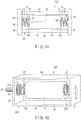
- FIG. 15 shows a damping device 15E according to a sixth embodiment.
- a main body portion 30 of a base member 20E of this embodiment is constituted of a pair of lateral plates 90 and 91.
- the base member 20E and the support portions 31 and 32 can be manufactured by a metal member such as a metal plate.
- common reference numbers are assigned to common parts in the two, and explanation of such parts is omitted.
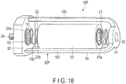
- FIG. 16 shows a damping device 15F according to a seventh embodiment.
- a main body portion 30 of a base member 20F of this embodiment is constituted of a plurality of (for example, three) rod portions 100. These rod portions 100 are arranged at predetermined intervals (regular intervals, for example) in a circumferential direction of a weight member 23. Consequently, the outer shape of the base member 20F can be formed relatively small.
- common reference numbers are assigned to common parts in the two, and explanation of such parts is omitted.
- a damping device is not limited to those of the above embodiments.
- the damping device in its broader aspect can be arranged in a vibration suppression target other than a vehicle seat.
- the orientation of the damping device to be arranged is determined in accordance with a direction in which vibration which should be suppressed is input.
- the first coil spring 21 of the damping device is deflected in the longitudinal direction along the axis of the base member 20, and the transverse direction along a plane perpendicular to the axis.
- the second coil spring 22 is also deflected in the longitudinal direction along the axis of the base member 20, and the transverse direction along a plane perpendicular to the axis.
- the weight member 23 moves in the longitudinal direction and the transverse direction.
- a spring constant in the longitudinal direction (direction along the axis) of the coil springs 21 and 22 is set such that a characteristic frequency in the longitudinal direction of the weight member 23 corresponds to a resonance frequency in the longitudinal direction of the vibration suppression target.
- a spring constant in the transverse direction (direction perpendicular to the axis) of the coil springs 21 and 22 is set such that a characteristic frequency in the transverse direction of the weight member 23 corresponds to a resonance frequency in the transverse direction of the vibration suppression target.
- the effective portion 41 of the first coil spring 21 should preferably include the end-turn adjoining portion 41a, on one side, whose contact with the first fixed-side end turn portion 40 is controlled, and the end-turn adjoining portion 41b, on the other side, whose contact with the first movable-side end turn portion 42 is controlled, so that the number of turns in a state where the first coil spring 21 is deflected in the second transverse direction becomes greater than the number of turns in a state where the fist coil spring 21 is deflected in the first transverse direction.
- the effective portion 51 of the second coil spring 22 should also include the end-turn adjoining portion 51a, on one side, whose contact with the second fixed-side end turn portion 50 is controlled, and the end-turn adjoining portion 51b, on the other side, whose contact with the second movable-side end turn portion 52 is controlled, so that the number of turns in a state where the second coil spring 22 is deflected in the second transverse direction becomes greater than the number of turns in a state where the second coil spring 22 is deflected in the first transverse direction.
- each member which constitutes the damping device such as the base member, the first coil spring, the second coil spring, and the weight member of the damping device, can be modified as needed in implementing the invention.
- the damping device may be arranged in a vibration suppression target other than the vehicle seat.
Abstract
Description
- The present invention relates to a damping device arranged in a vibration suppression target.
- In a vibration suppression target for which suppressing vibration is desired such as a member which constitutes a vehicle, a damping device may be arranged. A damping device described in, for example,
US 4,925,198 B (Patent Literature 1) orJP H01-309886 A Patent Literatures - When the inertial mass moves along the rod, friction is produced between the inertial mass and the rod. When the inertial mass moves along the housing, friction is produced between the inertial mass and the housing. Accordingly, in either case, in a low acceleration area, due to the friction, the inertial mass may not be operated. If a friction reduction member is used to minimize the friction, problems that the cost is increased, and the number of components is increased arise. Moreover, since the inertial mass moves in only one direction (axial direction), a damping effect can be exhibited only for the vibration applied in one direction. In order to suppress vibration in multiple directions, multiple damping devices are required.
- An object of the present invention is to provide a damping device capable of operating also in a low acceleration area, and suppressing vibration in multiple directions.
- The damping device of the present invention can be applied to various devices for which suppressing vibration is desired. While the damping device is suitable for suppressing vibration of a vehicle seat, for example, the purpose is not necessarily limited to this. The orientation of the damping device to be arranged is set in accordance with the specifications of the vibration suppression target, and is not limited to the embodiments described below.
- An embodiment of the present invention relates to a damping device, which is arranged in a vibration suppression target, including a base member fixed to the vibration suppression target, a first coil spring formed of a first wire, a second coil spring formed of a second wire, and a weight member arranged between the first coil spring and the second coil spring.
- The base member includes a main body portion including an axis, a first support portion provided on one end portion of the main body portion in an axial direction thereof, a second support portion provided on the other end portion in the axial direction of the main body portion. The first coil spring includes a first fixed-side end turn portion supported on the first support portion, a first effective portion extending in a direction toward the second support portion helically from the first fixed-side end turn portion, and a first movable-side end turn portion formed at a distal end of the first effective portion. The first coil spring is deflected in a longitudinal direction along the axis, and a transverse direction perpendicular to the axis.
- The second coil spring includes a second fixed-side end turn portion supported on the second support portion, a second effective portion extending in a direction toward the first support portion helically from the second fixed-side end turn portion, and a second movable-side end turn portion formed at a distal end of the second effective portion. The second coil spring is also deflected in the longitudinal direction along the axis, and the transverse direction perpendicular to the axis.
- The weight member is arranged in a state of compressing the first coil spring and the second coil spring. The weight member includes a first end portion supported on the first movable-side end turn portion, and a second end portion supported on the second movable-side end turn portion, and moves in the longitudinal direction and the transverse direction.
- According to the damping device of the present embodiment, the weight member can be moved in the longitudinal direction along the axis and the transverse direction perpendicular to the axis, without being substantially affected by the friction, and can be operated even in a low acceleration area. The weight member can also be moved in at least a first transverse direction and a second transverse direction within a plane perpendicular to the axis. Accordingly, a vibration suppression function can be exhibited effectively also for vibration to be applied in multiple directions. Also, since members such as a rod and a housing for guiding the weight member are unnecessary, and a friction reduction member is also unnecessary, there is also an advantage that the number of components can be reduced.
- In the damping device of the present embodiment, at least one of the effective portion of the first coil spring (first effective portion) and the effective portion of the second coil spring (second effective portion) may be controlled such that a spring constant derived in a state where the spring is deflected in the second transverse direction is smaller than a spring constant derived in a state where the spring is deflected in the first transverse direction.
- Transverse stiffness of the coil spring (i.e., the spring constant in the transverse direction) depends on a coil diameter, a free length of the coil spring (the length when no load is applied), and a compression length (the length when the coil spring is compressed to a predetermined length). By optimizing these three elements according to the specifications required for the damping device, the spring constants in the first transverse direction and the second transverse direction can be adjusted. However, depending on the specifications of the coil spring, relying on only these three elements may be insufficient to adjust the spring constants in the first transverse direction and the second transverse direction. In such a case, the effective portion (first effective portion) of the first coil spring should preferably include one end-turn adjoining portion whose contact with the first fixed-side end turn portion is controlled, and the other end-turn adjoining portion whose contact with the first movable-side end turn portion is controlled, so that the number of turns in a state where the first coil spring is deflected in the second transverse direction becomes greater than the number of turns in a state where the fist coil spring is deflected in the first transverse direction.
- The effective portion (second effective portion) of the second coil spring should preferably include one end-turn adjoining portion whose contact with the second fixed-side end turn portion is controlled, and the other end-turn adjoining portion whose contact with the second movable-side end turn portion is controlled, so that the number of turns in a state where the second coil spring is deflected in the second transverse direction becomes greater than the number of turns in a state where the second coil spring is deflected in the first transverse direction.
- An example of the first coil spring is slant shaped such that the first movable-side end turn portion becomes higher than the first fixed-side end turn portion in a free state of not supporting the weight member. The second coil spring is also slant shaped such that the second movable-side end turn portion becomes higher than the second fixed-side end turn portion in a state of not supporting the weight member. Further, in a state in which the weight of the weight member is applied to the first coil spring and the second coil spring, a central axis of the first coil spring and a central axis of the second coil spring may be made to be along the axis.
- The first support portion may include a groove for inserting the first fixed-side end turn portion, and the second support portion may include a groove for inserting the second fixed-side end turn portion. Further, the first end portion of the weight member may include a groove for inserting the first movable-side end turn portion, and the second end portion of the weight member may include a groove for inserting the second movable-side end turn portion. Further, a rotation stopping portion for preventing the weight member from rotating about the axis may be provided.
- A preferred embodiment may comprise a first through-hole which is formed in the first support portion, and penetrates in a direction along the axis, a second through-hole which is formed in the weight member, and extends in the direction along the axis, and a fixing bolt which is provided on the second support portion, and includes an operation portion arranged on the extension of the through-holes.
- The damping device according to one embodiment is arranged in a vehicle seat comprising a seat cushion and a seat back. The base member of the damping device of this embodiment is arranged in a seat back such that the axis is parallel to a width direction of the seat back. The effective portion (first effective portion) of the first coil spring includes one end-turn adjoining portion whose contact with the first fixed-side end turn portion is controlled, and the other end-turn adjoining portion whose contact with the first movable-side end turn portion is controlled, so that the number of turns in a state where the first coil spring is deflected in a front-to-back direction of the seat back becomes greater than the number of turns in a state where the first coil spring is deflected in a vertical direction of the seat back. Further, the effective portion (second effective portion) of the second coil spring includes one end-turn adjoining portion whose contact with the second fixed-side end turn portion is controlled, and the other end-turn adjoining portion whose contact with the second movable-side end turn portion is controlled, so that the number of turns in a state where the second coil spring is deflected in the front-to-back direction becomes greater than the number of turns in a state where the second coil spring is deflected in the vertical direction of the seat back. The weight member moves at least in the width direction, the front-to-back direction, and the vertical direction of the seat back. The spring constants of the first coil spring and the second coil spring when the weight member moves in the front-to-back direction are smaller than those when the weight member moves in the width direction and the vertical direction of the seat back. In this embodiment, a dimension of the weight member in the front-to-back direction may be smaller than a dimension of the same in the vertical direction. Further, a rotation stopping portion for preventing the weight member from
- The invention can be more fully understood from the following detailed description when taken in conjunction with the accompanying drawings, in which:
-
FIG. 1 is a perspective view of a vehicle seat comprising a damping device according to a first embodiment. -
FIG. 2 is a front view of the damping device shown inFIG. 1 . -
FIG. 3 is a perspective view of the damping device. -
FIG. 4 is a cross-sectional view of one end portion of the damping device. -
FIG. 5 is a cross-sectional view of the other end portion of the damping device. -
FIG. 6 is a side view of a first coil spring of the damping device. -
FIG. 7A is a front view of a state in which the coil spring is deflected to one side in a first transverse direction. -
FIG. 7B is a front view of a state in which the coil spring is deflected to the other side in the first transverse direction. -
FIG. 8A is a side view of a state in which the coil spring is deflected to one side in a second transverse direction. -
FIG. 8B is a side view of a state in which the coil spring is deflected to the other side in the second transverse direction. -
FIG. 9 is a graph showing the relationship between deflection and a load of the coil spring. -
FIG. 10 is a perspective view of a damping device according to a second embodiment. -
FIG. 11 is a front view of a part of the damping device shown inFIG. 10 . -
FIG. 12 is a front view of a damping device according to a third embodiment. -
FIG. 13 is a front view of a state before a weight member is mounted in a damping device according to a fourth embodiment. -
FIG. 14 is a front view of a damping device according to a fifth embodiment. -
FIG. 15 is a perspective view of a damping device according to a sixth embodiment. -
FIG. 16 is a perspective view of a damping device according to a seventh embodiment. - A damping device according to a first embodiment will be described with reference to
FIGS. 1 to 9 . -
FIG. 1 shows avehicle seat 10. Theseat 10 comprises aseat cushion 11 and a seat back 12. The seat back 12, which is an example of a vibration suppression target, includes aframe 13, and apad member 14 covering theframe 13. A dampingdevice 15 is arranged in the seat back 12. Arrow X inFIG. 1 represents a vertical direction of the seat back 12, and arrow Y represents a front-to-back direction of the same. Arrow Z indicates a width direction of the seat back 12. -
FIG. 2 is a front view of the dampingdevice 15, andFIG. 3 is a perspective view of the dampingdevice 15. The dampingdevice 15 includes abase member 20, afirst coil spring 21, asecond coil spring 22, aweight member 23, and a fixingbolt 24. Although thebase member 20 is made of metal in one example, thebase member 20 may be made of resin if the strength is sufficient. Thebase member 20 includes amain body portion 30 including an axis Z0, afirst support portion 31, and asecond support portion 32. Themain body portion 30 is constituted of a plurality ofrods 33. In this specification, a direction along the axis Z0 is referred to as an axial direction Z1. - The
first support portion 31 of thebase member 20 is provided on one end portion of themain body portion 30 in the axial direction thereof. Thesecond support portion 32 is provided on the other end portion of themain body portion 30 in the axial direction thereof. Thebase member 20 is fixed to theframe 13 of the seat back 12 (FIG. 1 ) by thebolt 24 such that the axis Z0 is parallel to the width direction of the seat back 12. -
FIG. 4 is a cross-sectional view of one end portion of the dampingdevice 15. A first through-hole 35 is formed in thefirst support portion 31 of thebase member 20. The first through-hole 35 extends in the axial direction Z1. In theweight member 23, a second through-hole 36 extending in the axial direction Z1 is formed. -
FIG. 5 is a cross-sectional view of the other end portion of the dampingdevice 15. In thesecond support portion 32, ahole 37 into which the fixingbolt 24 is inserted is formed. Anoperation portion 24a provided at a head portion of thebolt 24 is arranged on the extension of the through-holes FIG. 4 ) for rotating thebolt 24 is a rod-shaped wrench. By inserting thistool 38 into the first through-hole 35 and the second through-hole 36, a distal end of thetool 38 is fitted into theoperation portion 24a of thebolt 24. In this way, thebolt 24 is rotated. -
FIG. 6 is a side view of thefirst coil spring 21. Thefirst coil spring 21 is formed by shaping a first wire W1 made of spring steel helically. Thecoil spring 21 includes a first fixed-sideend turn portion 40, a firsteffective portion 41, and a first movable-sideend turn portion 42. In a state in which the first fixed-sideend turn portion 40 is supported on thefirst support portion 31, the firsteffective portion 41 extends in a direction toward thesecond support portion 32 helically from the first fixed-sideend turn portion 40. The first movable-sideend turn portion 42 is formed at a distal end of the firsteffective portion 41. - The first
effective portion 41 is a portion where adjacent winding portions of the wire W1 do not contact each other, and which functions effectively as a spring, in a state in which thefirst coil spring 21 is compressed to the maximum. The firsteffective portion 41 includes an end-turn adjoining portion 41a, on one side, whose position of contact with the first fixed-sideend turn portion 40 is varied, and an end-turn adjoining portion 41b, on the other side, whose position of contact with the first movable-sideend turn portion 42 is varied. The operation of these end-turn adjoining portions - The
second coil spring 22 is formed by shaping a second wire W2 made of spring steel helically. Thecoil spring 22 includes a second fixed-sideend turn portion 50, a secondeffective portion 51, and a second movable-sideend turn portion 52. In a state in which the second fixed-sideend turn portion 50 is supported on thesecond support portion 32, the secondeffective portion 51 extends in a direction toward thefirst support portion 31 helically from the second fixed-sideend turn portion 50. The second movable-sideend turn portion 52 is formed at a distal end of the secondeffective portion 51. - The second
effective portion 51 is a portion where adjacent winding portions of the wire W2 do not contact each other, and which functions effectively as a spring, in a state in which thesecond coil spring 22 is compressed to the maximum. As shown inFIG. 5 , the secondeffective portion 51 also includes an end-turn adjoining portion 51a, on one side, whose position of contact with the second fixed-sideend turn portion 50 is varied, and an end-turn adjoining portion 51b, on the other side, whose position of contact with the second movable-sideend turn portion 52 is varied. - In this specification, the direction along the axis Z0 (i.e., axial direction Z1) is referred to as a longitudinal direction. The axial direction Z1 is also a width direction of the seat back 12. Further, a direction along a plane perpendicular to the axial direction Z1 is referred to as a transverse direction. In other words, the transverse direction is a radial direction of the coil springs 21 and 22. Each of the
first coil spring 21 and thesecond coil spring 22 can be deflected in the longitudinal direction and the transverse direction. The transverse direction includes a first transverse direction X1 (FIG. 3 ) extending in the vertical direction of the seat back 12, and a second transverse direction Y1 along the front-to-back direction of the seat back 12. - In the damping
device 15 of the present embodiment, at least one of the firsteffective portion 41 and the secondeffective portion 51 may be controlled such that a spring constant derived when the spring is deflected in the second transverse direction Y1 is smaller than a spring constant derived when the spring is deflected in the first transverse direction X1. Since the shapes and functions of thefirst coil spring 21 and thesecond coil spring 22 are common to each other, thefirst coil spring 21 will be described as a typical example of the coil springs. -
FIG. 7A shows the state in which the movable-sideend turn portion 42 moves relatively to one side in the first transverse direction (i.e., a direction indicated by arrow X2). More specifically, the figure shows the state in which thecoil spring 21 is deflected to one side in the first transverse direction. At this time, the number of turns from point P1 where the fixed-sideend turn portion 40 is in contact with theeffective portion 41 to point P2 where the movable-sideend turn portion 42 is in contact with theeffective portion 41, in other words, the number of effective turns, is approximately 2.5 turns. -
FIG. 7B shows the state in which the movable-sideend turn portion 42 moves relatively to the other side in the first transverse direction (i.e., a direction indicated by arrow X3). More specifically, the figure shows the state in which thecoil spring 21 is deflected to the other side in the first transverse direction. At this time, the number of turns from point P3 where the fixed-sideend turn portion 40 is in contact with theeffective portion 41 to point P4 where the movable-sideend turn portion 42 is in contact with theeffective portion 41, in other words, the number of effective turns, is approximately 2.5 turns. -
FIG. 8A shows the state in which the movable-sideend turn portion 42 moves relatively to one side in the second transverse direction (i.e., a direction indicated by arrow Y2). More specifically, the figure shows the state in which thecoil spring 21 is deflected to one side in the second transverse direction. At this time, the number of turns from point P5 where the fixed-sideend turn portion 40 is in contact with the end-turn adjoining portions 41a, on one side, to point P6 where the movable-sideend turn portion 42 is in contact with the other end-turn adjoining portion 41b, in other words, the number of effective turns, is approximately 2.5 turns. -
FIG. 8B shows the state in which the movable-sideend turn portion 42 moves relatively to the other side in the second transverse direction (i.e., a direction indicated by arrow Y3). More specifically, the figure shows the state in which thecoil spring 21 is deflected to the other side in the second transverse direction. At this time, as the end-turn adjoining portions 41a, on one side, is separated from the fixed-sideend turn portion 40, the other end-turn adjoining portion 41b is separated from the movable-sideend turn portion 42. Accordingly, the number of turns from point P7 where the fixed-sideend turn portion 40 is in contact with theeffective portion 41 to point P8 where the movable-sideend turn portion 42 is in contact with theeffective portion 41, in other words, the number of effective turns, is approximately 3.0 turns. Here, since the number of effective turns takes on different values depending on the conditions such as the shapes of theend turn portions turn adjoining portions - Because contact between the end-
turn adjoining portions end turn portions effective portion 41 in a state where thecoil spring 21 is deflected in the second transverse direction (front-to-back direction of the seat back 12) becomes greater than the number of turns in a state where thecoil spring 21 is deflected in the first transverse direction (vertical direction). Accordingly, the spring constant derived when thecoil spring 21 is deflected in the second transverse direction becomes smaller than the spring constant derived when thecoil spring 21 is deflected in the first transverse direction. - As shown in
FIG. 5 , theeffective portion 51 of thesecond coil spring 22 also includes the end-turn adjoining portion 51a, on one side, and the end-turn adjoining portion 51b, on the other side, likewise thefirst coil spring 21. The operation of these end-turn adjoining portions turn adjoining portions first coil spring 21. In other words, thesecond coil spring 22 includes the end-turn adjoining portions effective portion 51 in a state where thesecond coil spring 22 is deflected in the second transverse direction (front-to-back direction of the seat back 12) is increased as compared to the number of turns in a state where thesecond coil spring 22 is deflected in the first transverse direction (vertical direction). - A spring constant in the longitudinal direction (axial direction Z1) of the coil springs 21 and 22 is set such that a characteristic frequency in a longitudinal direction of the
weight member 23 corresponds to a resonance frequency in the width direction of the seat back 12. A spring constant in the first transverse direction of the coil springs 21 and 22 is set such that a characteristic frequency in a vertical direction of theweight member 23 corresponds to a resonance frequency in the vertical direction of the seat back 12. A spring constant in the second transverse direction of the coil springs 21 and 22 is set such that a characteristic frequency in a front-to-back direction of theweight member 23 corresponds to a resonance frequency in the front-to-back direction of the seat back 12. - The
weight member 23 is arranged between thefirst coil spring 21 and thesecond coil spring 22 in such a state that it compresses thesecoil springs weight member 23 is made of metal, and has a cylindrical shape. Afirst end portion 23a of theweight member 23 is supported by the movable-sideend turn portion 42 of thefirst coil spring 21. Asecond end portion 23b of theweight member 23 is supported by the movable-sideend turn portion 52 of thesecond coil spring 22. Accordingly, theweight member 23 can be moved in at least the width direction, the front-to-back direction, and the vertical direction of the seat back 12. - As shown in
FIG. 4 , on thefirst support portion 31 of the dampingdevice 15 of the present embodiment, agroove 60 for inserting the first fixed-sideend turn portion 40 is formed. On thefirst end portion 23a of theweight member 23, agroove 61 for inserting the first movable-sideend turn portion 42 is formed. As shown inFIG. 5 , on thesecond support portion 32, agroove 62 for inserting the second fixed-sideend turn portion 50 is formed. On thesecond end portion 23b of theweight member 23, agroove 63 for inserting the second movable-sideend turn portion 52 is formed. - As described above, the number of turns of the
effective portions weight member 23 moves in the front-to-back direction is smaller than the spring constant of the same when theweight member 23 moves in the vertical direction. -
FIG. 9 is a graph showing the relationship between deflection and a load of thefirst coil spring 21. Thesecond coil spring 22 also has the relationship between deflection and a load similar to that of thefirst coil spring 21. A one-dot chain line L1 inFIG. 9 represents the relationship between the deflection and the load of thecoil spring 21 when theweight member 23 moves in the axial direction Z1 thereof (i.e., in the width direction of the seat back 12). A broken line L2 represents the relationship between the deflection and the load of thecoil spring 21 when theweight member 23 moves in the first transverse direction (vertical direction). A solid line L3 represents the relationship between the deflection and the load of thecoil spring 21 when theweight member 23 moves in the second transverse direction (front-to-back direction). - As described above, the number of turns of the
effective portion 41 when thecoil spring 21 moves in the front-to-back direction of the seat back 12 is greater than the number of turns of theeffective portion 41 when thecoil spring 21 moves in the vertical direction of the seat back 12. Accordingly, as shown inFIG. 9 , the spring constant of the coil springs 21 and 22 when theweight member 23 moves in the second transverse direction (front-to-back direction of the seat back 12) is smaller than the spring constant of the same when theweight member 23 moves in the first transverse direction (vertical direction of the seat back 12). - In terms of the structure of the
seat 10, the resonance frequency in the front-to-back direction of the seat back 12 is lower than each of the resonance frequencies in the width direction and the vertical direction. Accordingly, the dampingdevice 15 of the present embodiment is arranged such that the axis Z0 is parallel to the width direction of the seat back 12, and the first transverse direction corresponds to the vertical direction of the seat back 12. The second transverse direction corresponds to the front-to-back direction of the seat back 12. Consequently, by a single dampingdevice 15, vibrations in multiple directions which occur in the seat back 12 can be effectively suppressed, and in particular, the vibration in the front-to-back direction of the seat back 12 can be suppressed. -
FIG. 10 shows a dampingdevice 15A according to a second embodiment.FIG. 11 is a front view of a part of the dampingdevice 15A shown inFIG. 10 . Aweight member 23A of this embodiment has a flat rectangular shape, and a dimension T1 in the front-to-back direction is smaller than a dimension T2 in the vertical direction. Accordingly, this embodiment is advantageous in securing a space for accommodating the dampingdevice 15A in the case of a seat back having a restriction on the thickness in the front-to-back direction. Also, the dampingdevice 15A includesrotation stopping portions weight member 23A from rotating about an axis Z0, as shown inFIG. 11 . - As shown in
FIG. 10 , amain body portion 30 of abase member 20A of the dampingdevice 15A is provided on only one side of thebase member 20A. By this feature, not only is the structure of thebase member 20A simplified, but assembly of the dampingdevice 15A is also facilitated. In the dampingdevice 15A of the present embodiment, since the other structures and functions have commonalities with those of the dampingdevice 15 of the first embodiment, common reference numbers are assigned to common parts in the two, and explanation of such parts is omitted. -
FIG. 12 shows a dampingdevice 15B according to a third embodiment. On afirst support portion 31 and afirst end portion 23a of aweight member 23,rotation stopping portions weight member 23 from rotating about an axis Z0 are provided, respectively. Also on asecond support portion 32 and asecond end portion 23b of theweight member 23,rotation stopping portions weight member 23 from rotating about the axis Z0 are provided, respectively. In the dampingdevice 15B of the present embodiment, since the other structures and functions have commonalities with those of the dampingdevice 15 of the first embodiment, common reference numbers are assigned to common parts in the two, and explanation of such parts is omitted. -
FIG. 13 shows the state before a weight member is mounted in a dampingdevice 15C according to a fourth embodiment. Afirst coil spring 21 of this embodiment is shaped to have a coil central axis C1 inclined in such a way that a first movable-sideend turn portion 42 becomes higher than a first fixed-sideend turn portion 40 in a free state of not supporting the weight member. Asecond coil spring 22 is also shaped to have a coil central axis C2 inclined in such a way that a second movable-sideend turn portion 52 becomes higher than a second fixed-sideend turn portion 50 in a free state of not supporting the weight member. - In a state in which the weight of the
weight member 23 is applied to thefirst coil spring 21 and thesecond coil spring 22, the central axis C1 of thefirst coil spring 21 and the central axis C2 of thesecond coil spring 22 are along an axis Z0. In the dampingdevice 15C of the present embodiment, since the other structures and functions have commonalities with those of the dampingdevice 15 of the first embodiment, common reference numbers are assigned to common parts in the two, and explanation of such parts is omitted. -
FIG. 14 shows a dampingdevice 15D according to a fifth embodiment. On afirst support portion 31, a conicalconvex portion 80 which supports a first fixed-sideend turn portion 40 is provided. On afirst end portion 23a of aweight member 23, a conicalconvex portion 81 which supports a first movable-sideend turn portion 42 is provided. On asecond support portion 32, a conicalconvex portion 82 which supports a second fixed-sideend turn portion 50 is provided. On asecond end portion 23b of theweight member 23, a conicalconvex portion 83 which supports a second movable-sideend turn portion 52 is provided. Theweight member 23 is formed of solid metal. In the dampingdevice 15D of the present embodiment, since the other structures and functions have commonalities with those of the dampingdevice 15 of the first embodiment, common reference numbers are assigned to common parts in the two, and explanation of such parts is omitted. -
FIG. 15 shows a dampingdevice 15E according to a sixth embodiment. Amain body portion 30 of abase member 20E of this embodiment is constituted of a pair oflateral plates base member 20E and thesupport portions device 15E of the present embodiment, since the other structures and functions have commonalities with those of the dampingdevice 15 of the first embodiment, common reference numbers are assigned to common parts in the two, and explanation of such parts is omitted. -
FIG. 16 shows a dampingdevice 15F according to a seventh embodiment. Amain body portion 30 of abase member 20F of this embodiment is constituted of a plurality of (for example, three)rod portions 100. Theserod portions 100 are arranged at predetermined intervals (regular intervals, for example) in a circumferential direction of aweight member 23. Consequently, the outer shape of thebase member 20F can be formed relatively small. In the dampingdevice 15F of the present embodiment, since the other structures and functions have commonalities with those of the dampingdevice 15 of the first embodiment, common reference numbers are assigned to common parts in the two, and explanation of such parts is omitted. - A damping device according to the present invention is not limited to those of the above embodiments. The damping device in its broader aspect can be arranged in a vibration suppression target other than a vehicle seat. The orientation of the damping device to be arranged is determined in accordance with a direction in which vibration which should be suppressed is input. The
first coil spring 21 of the damping device is deflected in the longitudinal direction along the axis of thebase member 20, and the transverse direction along a plane perpendicular to the axis. Thesecond coil spring 22 is also deflected in the longitudinal direction along the axis of thebase member 20, and the transverse direction along a plane perpendicular to the axis. Theweight member 23 moves in the longitudinal direction and the transverse direction. - A spring constant in the longitudinal direction (direction along the axis) of the coil springs 21 and 22 is set such that a characteristic frequency in the longitudinal direction of the
weight member 23 corresponds to a resonance frequency in the longitudinal direction of the vibration suppression target. A spring constant in the transverse direction (direction perpendicular to the axis) of the coil springs 21 and 22 is set such that a characteristic frequency in the transverse direction of theweight member 23 corresponds to a resonance frequency in the transverse direction of the vibration suppression target. - The
effective portion 41 of thefirst coil spring 21 should preferably include the end-turn adjoining portion 41a, on one side, whose contact with the first fixed-sideend turn portion 40 is controlled, and the end-turn adjoining portion 41b, on the other side, whose contact with the first movable-sideend turn portion 42 is controlled, so that the number of turns in a state where thefirst coil spring 21 is deflected in the second transverse direction becomes greater than the number of turns in a state where thefist coil spring 21 is deflected in the first transverse direction. Preferably, theeffective portion 51 of thesecond coil spring 22 should also include the end-turn adjoining portion 51a, on one side, whose contact with the second fixed-sideend turn portion 50 is controlled, and the end-turn adjoining portion 51b, on the other side, whose contact with the second movable-sideend turn portion 52 is controlled, so that the number of turns in a state where thesecond coil spring 22 is deflected in the second transverse direction becomes greater than the number of turns in a state where thesecond coil spring 22 is deflected in the first transverse direction. - Needless to say, the quality of the material, shape, and arrangement of each member which constitutes the damping device, such as the base member, the first coil spring, the second coil spring, and the weight member of the damping device, can be modified as needed in implementing the invention. Also, the damping device may be arranged in a vibration suppression target other than the vehicle seat.
Claims (14)
- A damping device arranged in a vibration suppression target, the damping device comprising:a base member (20) (20A) (20E) (20F) including a main body portion (30) including an axis (Z0), a first support portion (31) provided on one side of the main body portion (30) in an axial direction (Z1) thereof, and a second support portion (32) provided on the other side of the main body portion (30) in the axial direction (Z1), the base member (20) (20A) (20E) (20F) being fixed to the vibration suppression target;characterized by further comprising:a first coil spring (21) which is formed of a first wire (W1), and includes a first fixed-side end turn portion (40) supported on the first support portion (31), a first effective portion (41) extending in a direction toward the second support portion (32) helically from the first fixed-side end turn portion (40), and a first movable-side end turn portion (42) formed at a distal end of the first effective portion (41), the first coil spring (21) being deflected in a longitudinal direction along the axis (Z0), and a transverse direction perpendicular to the axis (Z0);a second coil spring (22) which is formed of a second wire (W2), and includes a second fixed-side end turn portion (50) supported on the second support portion (32), a second effective portion (51) extending in a direction toward the first support portion (31) helically from the second fixed-side end turn portion (50), and a second movable-side end turn portion (52) formed at a distal end of the second effective portion (51), the second coil spring (22) being deflected in the longitudinal direction along the axis (Z0), and the transverse direction perpendicular to the axis (Z0); anda weight member (23) arranged between the first coil spring (21) and the second coil spring (22) in a state of compressing the first coil spring (21) and the second coil spring (22), the weight member (23) including a first end portion (23a) supported on the first movable-side end turn portion (42), and a second end portion (23b) supported on the second movable-side end turn portion (52), and being moved in the longitudinal direction and the transverse direction.
- The damping device of Claim 1, characterized in that the first effective portion (41) is controlled such that a spring constant derived when deflection occurs in a second transverse direction is smaller than a spring constant derived when deflection occurs in a first transverse direction.
- The damping device of Claim 1, characterized in that the second effective portion (51) is controlled such that a spring constant derived when deflection occurs in a second transverse direction is smaller than a spring constant derived when deflection occurs in a first transverse direction.
- The damping device of Claim 1, characterized in that each of the first effective portion (41) and the second effective portion (51) is controlled such that a spring constant derived when deflection occurs in a second transverse direction is smaller than a spring constant derived when deflection occurs in a first transverse direction.
- The damping device of Claim 1, characterized in that the first effective portion (41) includes one end-turn adjoining portion (41a) whose contact with the first fixed-side end turn portion (40) is controlled, and the other end-turn adjoining portion (41b) whose contact with the first movable-side end turn portion (42) is controlled, such that the number of turns in a state where deflection occurs in a second transverse direction becomes greater than the number of turns in a state where deflection occurs in a first transverse direction.
- The damping device of Claim 1, characterized in that the second effective portion (51) includes one end-turn adjoining portion (51a) whose contact with the second fixed-side end turn portion (50) is controlled, and the other end-turn adjoining portion (51b) whose contact with the second movable-side end turn portion (52) is controlled, such that the number of turns in a state where deflection occurs in a second transverse direction becomes greater than the number of turns in a state where deflection occurs in a first transverse direction.
- The damping device of Claim 5, characterized in that the second effective portion (51) includes one end-turn adjoining portion (51a) whose contact with the second fixed-side end turn portion (50) is controlled, and the other end-turn adjoining portion (51b) whose contact with the second movable-side end turn portion (52) is controlled, such that the number of turns in a state where deflection occurs in the second transverse direction becomes greater than the number of turns in a state where deflection occurs in the first transverse direction.
- The damping device of Claim 1, characterized in that:the first coil spring (21) is slant shaped such that the first movable-side end turn portion (42) becomes higher than the first fixed-side end turn portion (40) in a free state of not supporting the weight member (23);the second coil spring (22) is slant shaped such that the second movable-side end turn portion (52) becomes higher than the second fixed-side end turn portion (50) in the free state of not supporting the weight member (23); anda central axis (C1) of the first coil spring (21) and a central axis (C2) of the second coil spring (22) are along the axis (Z0) in a state in which weight of the weight member (23) is applied to the first coil spring (21) and the second coil spring (22).
- The damping device of Claim 1, characterized in that:the first support portion (31) includes a groove (60) for inserting the first fixed-side end turn portion (40);the second support portion (32) includes a groove (61) for inserting the second fixed-side end turn portion (50);the first end portion (23a) of the weight member (23) includes a groove (61) for inserting the first movable-side end turn portion (42); andthe second end portion (23b) of the weight member (23) includes a groove (63) for inserting the second movable-side end turn portion (52).
- The damping device of Claim 1, characterized by further comprising a rotation stopping portion (70) (71) (72) (73) for preventing the weight member (23) from rotating about the axis (Z0).
- The damping device of Claim 1, characterized in that the damping device comprises:a first through-hole (35) which is formed in the first support portion (31), and penetrates in a direction along the axis (Z0);a second through-hole (36) which is formed in the weight member (23), and penetrates in the direction along the axis (Z0); anda fixing bolt (24) which is provided on the second support portion (32), and includes an operation portion (24a) arranged on an extension of the second through-hole (36).
- A damping device arranged in a vehicle seat (10) comprising a seat cushion (11) and a seat back (12), the damping device comprising:a base member (20) (20A) (20E) (20F) including a main body portion (30) including an axis (Z0), a first support portion (31) provided on one side of the main body portion (30) in an axial direction (Z1) thereof, and a second support portion (32) provided on the other side of the main body portion (30) in the axial direction (Z1), the base member (20) (20A) (20E) (20F) being fixed to the seat back (12) such that the axis (Z0) is parallel to a width direction (Z) of the seat back (12);characterized by further comprising:a first coil spring (21) which is formed of a first wire (W1), and includes a first fixed-side end turn portion (40) supported on the first support portion (31), a first effective portion (41) extending in a direction toward the second support portion (32) helically from the first fixed-side end turn portion (40), and a first movable-side end turn portion (42) formed at a distal end of the first effective portion (41), the first effective portion (41) including one end-turn adjoining portion (41a) whose contact with the first fixed-side end turn portion (40) is controlled, and the other end-turn adjoining portion (41b) whose contact with the first movable-side end turn portion (42) is controlled, such that the number of turns in a state where deflection occurs in a front-to-back direction (Y) of the seat back (12) becomes greater than the number of turns in a state where deflection occurs in a vertical direction (X) of the seat back (12) ;a second coil spring (22) which is formed of a second wire (W2), and includes a second fixed-side end turn portion (50) supported on the second support portion (32), a second effective portion (51) extending in a direction toward the first support portion (31) helically from the second fixed-side end turn portion (50), and a second movable-side end turn portion (52) formed at a distal end of the second effective portion (51), the second effective portion (51) including one end-turn adjoining portion (51a) whose contact with the second fixed-side end turn portion (50) is controlled, and the other end-turn adjoining portion (51b) whose contact with the second movable-side end turn portion (52) is controlled, such that the number of turns in a state where deflection occurs in the front-to-back direction (Y) becomes greater than the number of turns in a state where deflection occurs in the vertical direction (X) of the seat back (12); anda weight member (23) arranged between the first coil spring (21) and the second coil spring (22) in a state of compressing the first coil spring (21) and the second coil spring (22), the weight member (23) including a first end portion (23a) supported on the first movable-side end turn portion (42), and a second end portion (23b) supported on the second movable-side end turn portion (52), and being moved in at least the width direction (Z), the front-to-back direction (Y), and the vertical direction (X) of the seat back (12),a spring constant of each of the first coil spring (21) and the second coil spring (22) when the weight member (23) moves in the front-to-back direction (Y) of the seat back (12) being smaller than a spring constant derived when the weight member (23) moves in the width direction (Z) and the vertical direction (X) of the seat back (12).
- The damping device of Claim 12, characterized in that a dimension (T1) of the weight member (23) in the front-to-back direction is smaller than a dimension of the weight member (23) in the vertical direction.
- The damping device of Claim 13, characterized by further comprising a rotation stopping portion (70) (71) (72) (73) for preventing the weight member (23) from rotating about the axis (Z0).
Applications Claiming Priority (1)
| Application Number | Priority Date | Filing Date | Title |
|---|---|---|---|
| US15/911,609 US10443670B2 (en) | 2018-03-05 | 2018-03-05 | Damping device |
Publications (1)
| Publication Number | Publication Date |
|---|---|
| EP3536550A1 true EP3536550A1 (en) | 2019-09-11 |
Family
ID=65628666
Family Applications (1)
| Application Number | Title | Priority Date | Filing Date |
|---|---|---|---|
| EP19159704.6A Withdrawn EP3536550A1 (en) | 2018-03-05 | 2019-02-27 | Damping device |
Country Status (3)
| Country | Link |
|---|---|
| US (1) | US10443670B2 (en) |
| EP (1) | EP3536550A1 (en) |
| JP (1) | JP2019152332A (en) |
Families Citing this family (4)
| Publication number | Priority date | Publication date | Assignee | Title |
|---|---|---|---|---|
| JP6370723B2 (en) * | 2015-01-30 | 2018-08-08 | ニチアス株式会社 | Connector and shield |
| US11590870B2 (en) * | 2017-08-31 | 2023-02-28 | Pioneer Corporation | Seat |
| US11125295B2 (en) * | 2019-08-30 | 2021-09-21 | Nhk International Corporation | Damping device |
| CN111993965B (en) * | 2020-08-31 | 2021-12-28 | 盐城市华悦汽车部件有限公司 | Car seat spring shock-absorbing structure convenient to dismantle and change |
Citations (5)
| Publication number | Priority date | Publication date | Assignee | Title |
|---|---|---|---|---|
| JPH01309886A (en) | 1988-02-12 | 1989-12-14 | Yamaha Motor Co Ltd | Steering gear of motorcycle |
| US4925198A (en) | 1988-02-12 | 1990-05-15 | Yamaha Hatsudoki Kabushiki Kaisha | Shimmy damping system for steerable vehicles |
| JPH109337A (en) * | 1996-06-20 | 1998-01-13 | Nippon Steel Corp | Damping device |
| US5816373A (en) * | 1997-03-21 | 1998-10-06 | Honeywell Inc. | Pneumatic tuned mass damper |
| DE29908839U1 (en) * | 1999-05-12 | 1999-08-05 | Technip Germany Gmbh | Device for damping vibrations |
Family Cites Families (18)
| Publication number | Priority date | Publication date | Assignee | Title |
|---|---|---|---|---|
| US2960189A (en) * | 1956-11-19 | 1960-11-15 | Kearney & Trecker Corp | Vibration dampener |
| US3774730A (en) * | 1972-04-19 | 1973-11-27 | Nl Industries Inc | Tool holder |
| US4550812A (en) * | 1978-08-04 | 1985-11-05 | United Technologies Corporation | Fixed position, fixed frequency pendular-type vibration absorber with frequency linearization |
| US4238104A (en) * | 1978-08-14 | 1980-12-09 | Rex Hamilton | Energy absorbing motor mount assembly |
| JPS63111337U (en) | 1987-01-14 | 1988-07-18 | ||
| JPH06119770A (en) * | 1992-08-18 | 1994-04-28 | Sony Corp | Vibration proof mechanism |
| US6009985A (en) * | 1997-02-10 | 2000-01-04 | Lord Corporation | Efficient multi-directional active vibration absorber assembly |
| TW408314B (en) * | 1997-08-22 | 2000-10-11 | Kenwood Corp | Supporting structure of floating chassis of disc apparatus |
| US6481701B2 (en) * | 2001-03-09 | 2002-11-19 | Delphi Technologies, Inc. | Spring having coils of varying diameters |
| US6634472B1 (en) * | 2002-04-03 | 2003-10-21 | Toren S. Davis | Tuned mass damper with translational axis damping |
| DE102005019323B3 (en) * | 2005-04-26 | 2006-07-13 | SGF Süddeutsche Gelenkscheibenfabrik GmbH & Co KG | Vibration damper for attaching to seat of motor vehicle, has support frame constructed in one piece for attaching to seat of vehicle, and two elastic connecting elements formed integrally on support frame and oscillating weight |
| US7586236B2 (en) * | 2005-10-07 | 2009-09-08 | The United States Of America As Represented By The Secretary Of The Navy | Tri-axial hybrid vibration isolator |
| JP2007298067A (en) | 2006-04-28 | 2007-11-15 | Asahi Kasei Homes Kk | Dynamic damper and its adjusting method |
| FR2924191B1 (en) * | 2007-11-22 | 2009-12-11 | Astrium Sas | MODULAR DEVICE FOR MULTI-AXIS ISOLATION OF VIBRATION AND SHOCK, BASED ON ELASTOMER. |
| US9457635B2 (en) * | 2010-09-23 | 2016-10-04 | Renton Coil Spring Company | Magnetic damper |
| CN103343496B (en) * | 2013-07-10 | 2016-06-08 | 铁道第三勘察设计院集团有限公司 | A kind of track bump leveller |
| US9541149B2 (en) * | 2014-09-04 | 2017-01-10 | The Boeing Company | Translational tuned mass damper with continuously adjustable damping characteristics for application to high speed wind tunnel testing |
| JP6539732B2 (en) * | 2015-05-28 | 2019-07-03 | アディエント ルクセンブルク ホールディング エス.エー アール.エル. | Dynamic damper, vehicle seat, and vehicle equipment |
-
2018
- 2018-03-05 US US15/911,609 patent/US10443670B2/en not_active Expired - Fee Related
-
2019
- 2019-02-12 JP JP2019022748A patent/JP2019152332A/en active Pending
- 2019-02-27 EP EP19159704.6A patent/EP3536550A1/en not_active Withdrawn
Patent Citations (5)
| Publication number | Priority date | Publication date | Assignee | Title |
|---|---|---|---|---|
| JPH01309886A (en) | 1988-02-12 | 1989-12-14 | Yamaha Motor Co Ltd | Steering gear of motorcycle |
| US4925198A (en) | 1988-02-12 | 1990-05-15 | Yamaha Hatsudoki Kabushiki Kaisha | Shimmy damping system for steerable vehicles |
| JPH109337A (en) * | 1996-06-20 | 1998-01-13 | Nippon Steel Corp | Damping device |
| US5816373A (en) * | 1997-03-21 | 1998-10-06 | Honeywell Inc. | Pneumatic tuned mass damper |
| DE29908839U1 (en) * | 1999-05-12 | 1999-08-05 | Technip Germany Gmbh | Device for damping vibrations |
Also Published As
| Publication number | Publication date |
|---|---|
| US20190271370A1 (en) | 2019-09-05 |
| US10443670B2 (en) | 2019-10-15 |
| JP2019152332A (en) | 2019-09-12 |
Similar Documents
| Publication | Publication Date | Title |
|---|---|---|
| EP3536550A1 (en) | Damping device | |
| US9694638B2 (en) | Spring rubber seat and strut-type suspension | |
| US6193225B1 (en) | Non-linear non-circular coiled spring | |
| EP3004682B1 (en) | Self-tuned mass damper and system comprising the same | |
| CN107850066B (en) | Refrigerant compressor | |
| US11333216B2 (en) | Connector | |
| US2680284A (en) | Method of making dampers for vibration isolators | |
| EP3312055A1 (en) | Vehicle attachment component | |
| US1988295A (en) | Yieldable supporting structure | |
| KR102435143B1 (en) | shock absorber and metal cover | |
| JP5804252B2 (en) | Grommet | |
| US11125295B2 (en) | Damping device | |
| US9528548B2 (en) | Center bearing support | |
| US8523153B2 (en) | Spring | |
| US11754141B2 (en) | Spring element | |
| EP4180688A1 (en) | Vibration damping device intended to damp the vibrations between two mechanical pieces | |
| JP5112226B2 (en) | Fastening mechanism and vibration isolator using the same | |
| JPH07259907A (en) | Coil compression spring device | |
| CN209767302U (en) | Motor assembly | |
| KR101362927B1 (en) | Wire rope isolator and vibration isolation system using the same | |
| JP3392202B2 (en) | Dynamic damper | |
| JP2023119363A (en) | Vibration reduction device and vehicle seat | |
| JP6905456B2 (en) | Upper mount for active damper | |
| JP2021162143A (en) | Vibration control mount | |
| WO2011129208A1 (en) | Spring |
Legal Events
| Date | Code | Title | Description |
|---|---|---|---|
| PUAI | Public reference made under article 153(3) epc to a published international application that has entered the european phase |
Free format text: ORIGINAL CODE: 0009012 |
|
| STAA | Information on the status of an ep patent application or granted ep patent |
Free format text: STATUS: THE APPLICATION HAS BEEN PUBLISHED |
|
| AK | Designated contracting states |
Kind code of ref document: A1 Designated state(s): AL AT BE BG CH CY CZ DE DK EE ES FI FR GB GR HR HU IE IS IT LI LT LU LV MC MK MT NL NO PL PT RO RS SE SI SK SM TR |
|
| AX | Request for extension of the european patent |
Extension state: BA ME |
|
| STAA | Information on the status of an ep patent application or granted ep patent |
Free format text: STATUS: REQUEST FOR EXAMINATION WAS MADE |
|
| 17P | Request for examination filed |
Effective date: 20200213 |
|
| RBV | Designated contracting states (corrected) |
Designated state(s): AL AT BE BG CH CY CZ DE DK EE ES FI FR GB GR HR HU IE IS IT LI LT LU LV MC MK MT NL NO PL PT RO RS SE SI SK SM TR |
|
| STAA | Information on the status of an ep patent application or granted ep patent |
Free format text: STATUS: THE APPLICATION HAS BEEN WITHDRAWN |
|
| 18W | Application withdrawn |
Effective date: 20220210 |