EP3536526A1 - Air conditioning unit for vehicle - Google Patents
Air conditioning unit for vehicle Download PDFInfo
- Publication number
- EP3536526A1 EP3536526A1 EP17867798.5A EP17867798A EP3536526A1 EP 3536526 A1 EP3536526 A1 EP 3536526A1 EP 17867798 A EP17867798 A EP 17867798A EP 3536526 A1 EP3536526 A1 EP 3536526A1
- Authority
- EP
- European Patent Office
- Prior art keywords
- air
- blower
- heater
- air conditioning
- bypass passage
- Prior art date
- Legal status (The legal status is an assumption and is not a legal conclusion. Google has not performed a legal analysis and makes no representation as to the accuracy of the status listed.)
- Granted
Links
Images



Classifications
-
- B—PERFORMING OPERATIONS; TRANSPORTING
- B60—VEHICLES IN GENERAL
- B60H—ARRANGEMENTS OF HEATING, COOLING, VENTILATING OR OTHER AIR-TREATING DEVICES SPECIALLY ADAPTED FOR PASSENGER OR GOODS SPACES OF VEHICLES
- B60H1/00—Heating, cooling or ventilating devices
- B60H1/00007—Combined heating, ventilating, or cooling devices
- B60H1/00021—Air flow details of HVAC devices
- B60H1/00064—Air flow details of HVAC devices for sending air streams of different temperatures into the passenger compartment
-
- B—PERFORMING OPERATIONS; TRANSPORTING
- B60—VEHICLES IN GENERAL
- B60H—ARRANGEMENTS OF HEATING, COOLING, VENTILATING OR OTHER AIR-TREATING DEVICES SPECIALLY ADAPTED FOR PASSENGER OR GOODS SPACES OF VEHICLES
- B60H1/00—Heating, cooling or ventilating devices
- B60H1/00007—Combined heating, ventilating, or cooling devices
- B60H1/00021—Air flow details of HVAC devices
- B60H2001/0015—Temperature regulation
- B60H2001/00164—Temperature regulation with more than one by-pass
-
- B—PERFORMING OPERATIONS; TRANSPORTING
- B60—VEHICLES IN GENERAL
- B60H—ARRANGEMENTS OF HEATING, COOLING, VENTILATING OR OTHER AIR-TREATING DEVICES SPECIALLY ADAPTED FOR PASSENGER OR GOODS SPACES OF VEHICLES
- B60H1/00—Heating, cooling or ventilating devices
- B60H1/00007—Combined heating, ventilating, or cooling devices
- B60H1/00021—Air flow details of HVAC devices
- B60H2001/00185—Distribution of conditionned air
Definitions
- the present disclosure relates to an air conditioning unit for a vehicle.
- the air conditioning unit for a vehicle includes a casing, a first centrifugal multi-blade fan that blows air into an upper air passage formed on an upper side in the casing, and a second centrifugal multi-blade fan that blows air into a lower air passage formed on a lower side in the casing.
- the air conditioning unit for a vehicle further includes a cooling heat exchanger disposed to extend across the upper air passage and the lower air passage, and a heating heat exchanger that is disposed on a downstream side of the cooling heat exchanger in an air flow direction. Bypass passages that bypass the heating heat exchanger are formed above and below the heating heat exchanger.
- Patent Literature 1 JP 2015-080959 A
- the upper and lower bypass passages in the air conditioning unit for a vehicle described in Patent Literature 1 have substantially the same passage areas and therefore it is difficult to increase a difference between a volume of air flowing through the upper bypass passage and a volume of air flowing through the lower bypass passage. Therefore, it is impossible to blow a sufficient flow rate of air from the upper bypass passage through a blow outlet toward a face of an occupant in a vehicle interior, for example.
- the first and second centrifugal multi-blade fans blow the air to the cooling heat exchanger like the air conditioning unit for a vehicle described in Patent Literature 1
- the first and second centrifugal multi-blade fans are disposed so that rotation axes of the first and second centrifugal multi-blade fans are substantially parallel to an air inflow face of the cooling heat exchanger.
- fans having large radial dimensions are used in order to increase volumes of blown air.
- a length of the cooling heat exchanger in a direction orthogonal to the air inflow face in the air conditioning unit becomes long, which increases a size of the air conditioning case.
- an air conditioning unit for a vehicle includes: an air conditioning case; a blower disposed in the air conditioning case and configured to draw air from an opening provided on one end side of the blower in a rotation axis of the blower and blow the air radially outward from the rotation axis; a cooler disposed upstream of the blower in an air flow direction and configured to cool the air flowing in the air conditioning case; and a heater disposed downstream of the blower in the air flow direction and configured to heat the air which has been cooled in the cooler.
- the air conditioning case includes an upper bypass passage through which the air blown out of the blower bypasses the heater on an upper side of the heater, a lower bypass passage through which the air bypasses the heater on a lower side of the heater, a first opening provided downstream of the upper bypass passage in the air flow direction, and a second opening provided downstream of the lower bypass passage in the air flow direction.
- the opening of the blower faces an air outflow face of the cooler.
- the heater is disposed in the air conditioning case such that a passage area of the upper bypass passage is larger than a passage area of the lower bypass passage.
- the air conditioning unit for a vehicle includes the blower that draws from the opening provided on the one end side of the blower in the rotation axis and blows the air radially outward from the rotation axis. Further, the opening of the blower faces the air outflow face of the cooler. Therefore, it is possible to reduce a length of the cooler in a direction orthogonal to the air outflow face in the air conditioning unit, and thereby the air conditioning case can be miniaturized. Moreover, the heater is disposed in the air conditioning case so that the passage area of the upper bypass passage is larger than the passage area of the lower bypass passage. Therefore, it is possible to increase the flow rate of air blown out of the air conditioning case through the upper bypass passage.
- FIGS. 1 to 3 An air conditioning unit for a vehicle according to a first embodiment will be described with reference to FIGS. 1 to 3 .
- Respective arrows indicating "up”, “down”, “left”, “right”, “front”, and “rear” in the drawings show an up-down direction, a left-right direction, and a front-rear direction when the air conditioning unit for a vehicle is mounted on a vehicle.
- the air conditioning unit for a vehicle includes an air conditioning case 12 that adjusts air to be blown into a vehicle interior to a desired temperature.
- the air conditioning case 12 is disposed inside an instrument panel 9 provided in a forefront part in the vehicle interior.
- the air conditioning case 12 is connected to a defroster blow outlet 91, face blow outlets 92a to 92d, and foot blow outlets 93a, 93b via ducts (not shown).
- the air conditioning case 12 can blow out the air adjusted to the desired temperature into the vehicle interior through the defroster blow outlet 91, the face blow outlets 92a to 92d, and the foot blow outlets 93a, 93b.
- the defroster blow outlet 91 is a blow outlet that blows out the air, adjusted to the temperature in the air conditioning case 12, toward a vehicle windshield (not shown).
- the defroster blow outlet 91 is provided in a forefront part of the instrument panel 9.
- the face blow outlets 92a to 92d are blow outlets that blow the air, adjusted to the temperature in the air conditioning case 12, toward faces of occupants sitting in front seats SEr, SEI in the vehicle interior.
- the face blow outlets 92a to 92d are provided behind the defroster blow outlet 91 on the instrument panel 9.
- the foot blow outlets 93a, 93b are blow outlets that blow the air, adjusted to the temperature in the air conditioning case 12, toward lower bodies of the occupants sitting in the front seats SEr, SEI in the vehicle interior.
- the foot blow outlets 93a, 93b are open inside the instrument panel 9.
- the foot blow outlets 93a, 93b in the present embodiment are a right foot blow outlet 93a that blows out the air mainly into a right space SPr in the vehicle interior and a left foot blow outlet 93b that blows out the air mainly into a left space SPI in the vehicle interior.
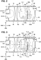
- FIG. 2 is a sectional view of a main structure of the air conditioning unit for a vehicle in the present embodiment.
- the air conditioning case 12 is a member that is made of resin and forms an outer shell of the air conditioning unit for a vehicle.
- FIG. 1 shows a main part of the entire air conditioning case 12.
- the air conditioning case 12 has a partition wall 123 that separates an outside air introducing port 121 for introducing outside air which is air outside the vehicle interior and an inside air introducing port 122 for introducing inside air which is air inside the vehicle interior from each other.
- the outside air which is the air outside the vehicle interior or the inside air which is the air inside the vehicle interior is introduced by a blower 20 into the air conditioning case 12.
- the outside air or the inside air introduced into the air conditioning case 12 flows into an evaporator 16.
- the evaporator 16 is a cooling heat exchanger, i.e., a cooler that cools the air flowing through the air conditioning case 12.
- the evaporator 16 is housed in the air conditioning case 12 and disposed so that the outside air or the inside air introduced into the air conditioning case 12 flows into the evaporator 16.
- the evaporator 16 forms a known refrigeration cycle device, through which refrigerant circulates, together with a compressor, a condenser, and an expansion valve (not shown). The evaporator 16 cools the air passing through the evaporator 16 by evaporation of the refrigerant.
- the blower 20 is a centrifugal blower that draws in the air, introduced into the inside air introducing port 122 or the outside air introducing port 121, from an opening 201 provided on one end side of a rotation axis CL1 and blows the air outward in a radial direction of the rotation axis CL1.
- the blower 20 is disposed on a downstream side of the evaporator 16 in an air flow direction, which is what is called a suction layout.
- the blower 20 draws in the air from the opening 201 as shown by arrows FL1 in FIG. 3 and blows the air outward in the radial direction of the rotation axis CL1 as shown by arrows FL2, FL3.
- the blower 20 is disposed so that the opening 201 of the blower 20 faces an air outflow face 16b of the evaporator 16.
- the blower 20 is disposed so that the rotation axis CL1 of the blower 20 is substantially orthogonal to the air outflow face 16b of the evaporator 16.
- the heater core 18 is disposed on a downstream side of the evaporator 16 in the air flow direction in the air conditioning case 12.
- the heater core 18 is disposed at a center in the up-down direction in the air conditioning case 12.
- the heater core 18 is in such a size as to be concealed in the up-down direction by a projection of the blower 20 in a direction from the air outflow face 16b of the evaporator 16 toward the heater core 18.
- the heater core 18 is for heating the air flowing out of the evaporator 16 with engine cooling water which is warm water, i.e., a heater.
- An upper bypass passage 125a is formed above the heater core 18 and a lower bypass passage 125b is formed below the heater core 18.
- the air conditioning case 12 has the upper bypass passage 125a that allows the air flowing out of the evaporator 16 to detour over the heater core 18 and the lower bypass passage 125b that allows the air to detour under the heater core 18.
- a first air mix door 24a and a second air mix door 24b are provided.
- the first air mix door 24a is disposed in the upper bypass passage 125a.
- the first air mix door 24a is a sliding door mechanism and slid by an electric actuator (not shown).
- the first air mix door 24 adjusts a ratio between a volume of air passing through the heater core 18 and a volume of air passing through the upper bypass passage 125a detouring over the heater core 18 in the air conditioning case 12 with its sliding position.
- the second air mix door 24b is disposed in the lower bypass passage 125b.
- the second air mix door 24b is a sliding door mechanism and slid by an electric actuator (not shown).
- the second air mix door 24b adjusts a ratio between a volume of air passing through the heater core 18 and a volume of air passing through the lower bypass passage 125b detouring under the heater core 18 in the air conditioning case 12 with its sliding position.
- the second air mix door 24b is disposed in the lower bypass passage 125b.
- the second air mix door 24b is the sliding door mechanism similar to the first air mix door 24a and slid by the electric actuator (not shown).
- the second air mix door 24b adjusts the ratio between the volume of air passing through the heater core 18 and the volume of air passing through the lower bypass passage 125b detouring under the heater core 18 in the air conditioning case 12 with its sliding position.
- the air cooled in the evaporator 16 is drawn into the opening 201 of the blower 20 and blown outward in the radial direction of the rotation axis CL1 of the blower 20.
- the air blown out of the blower 20 passes through the heater core 18, the upper bypass passage 125a, and the lower bypass passage 125b, respectively, and the flows of air are mixed on the downstream side of the heater core 18 in the air flow direction.
- the ratio between the volume of air passing through the heater core 18 and the volume of air passing through the upper bypass passage 125a detouring over the heater core 18 in the air conditioning case 12 is adjusted.
- the air at the adjusted air volume ratio is blown out into the vehicle interior mainly from the face opening 126 through the face blow outlets 92a to 92d and introduced into the vehicle interior from the defroster opening 127 through the defroster blow outlet 91.
- the ratio between the volume of air passing through the heater core 18 and the volume of air passing through the lower bypass passage 125b detouring under the heater core 18 in the air conditioning case 12 is adjusted. Then, the air at the adjusted air volume ratio is introduced into the vehicle interior mainly from the foot opening 128 through the foot blow outlets 93a, 93b.
- the heater core 18 is disposed in the air conditioning case 12 so that the upper bypass passage 125a has a larger passage area than the lower bypass passage 125b. Therefore, a larger volume of air is blown out of the air conditioning case through the upper bypass passage 125a than in the case where the upper bypass passage 125a has an equal passage area to the lower bypass passage 125b. In this way, it is possible to blow a sufficient flow rate of air toward the faces of the occupants in the vehicle interior.
- the present air conditioning unit for a vehicle includes the air conditioning case 12 and the blower 20 that is disposed in the air conditioning case 12 and blows the air, drawn from the opening 201 provided on the one end side of the rotation axis CL1, outward in the radial direction of the rotation axis CL1.
- the air conditioning unit for a vehicle further includes the evaporator 16 that is disposed on an upstream side of the blower 20 in the air flow direction and cools the air flowing through the air conditioning case 12 and the heater core 18 that is disposed on the downstream side of the blower 20 in the air flow direction and heats the air cooled in the evaporator 16.
- the air conditioning case 12 has the upper bypass passage 125a that allows the air blown out of the blower 20 to detour over the heater core 18 and the lower bypass passage 125b that allows the air to detour under the heater core 18.
- the air conditioning case 12 further includes the first opening 126 that is formed on a downstream side of the upper bypass passage 125a in the air flow direction and the second opening 128 that is formed on a downstream side of the lower bypass passage 125b in the air flow direction.
- the blower 20 is disposed so that the opening 201 faces the air outflow face 16b of the evaporator 16 and the heater core 18 is disposed in the air conditioning case so that the upper bypass passage 125a has the larger passage area than the lower bypass passage 125b.
- the air conditioning unit for a vehicle includes the blower 20 that blows the air, drawn from the opening 201 provided on the one end side of the rotation axis CL1, outward in the radial direction of the rotation axis CL1 and the blower 20 is disposed so that the opening 201 faces the air outflow face 16b of the evaporator 16. Therefore, it is possible to reduce a length of the cooler in a direction orthogonal to the air outflow face in the air conditioning unit to thereby miniaturize the air conditioning case. It is possible to achieve what is called a centered layout in which the air conditioning unit for a vehicle is disposed at a center in the left-right direction of the vehicle.
- the heater core 18 is disposed in the air conditioning case 12 so that the upper bypass passage 125a has the larger passage area than the lower bypass passage 125b, it is possible to increase the volume of air blown out of the air conditioning case 12 through the upper bypass passage 125a.
- the evaporator 16 creates a ventilation resistance.
- the blower 20 is disposed on the downstream side of the evaporator 16 in the air flow direction. In this way, it is possible to introduce the air blown out of the blower 20 as it is into the face opening 126 through the upper bypass passage 125a. Therefore, it is possible to further increase the volume of air blown out of the air conditioning case 12 through the upper bypass passage 125a.
- the heater core 18 is disposed so that a center of an air inflow face 18a into which the air flows is at a position lower than a center of the air outflow face 16b of the evaporator 16.
- the heater core 18 is disposed so that the center of the air inflow face 18b of the heater core 18 is at the position lower than the rotation axis CL1 of the blower 20.
- the center of the air inflow face 18b of the heater core 18 is at the position lower than the rotation axis CL1 of the blower 20, it is possible to make the passage area of the upper bypass passage 125a larger than the passage area of the lower bypass passage 125b.
- the face opening 126 communicating with the face blow outlets 92a to 92d that blow the air toward the faces of the occupants in the vehicle interior can serve as the first opening.
- the foot opening 128 communicating with the foot blow outlets 93a, 93b that blow the air toward the feet of the occupants in the vehicle interior can serve as the second opening.
- the blower 20 in the present embodiment blows the air, drawn from the opening 201 provided on the one end side of the rotation axis CL1, outward in the radial direction of the rotation axis CL1. If the opening 201 of the blower 20 is disposed to face the air outflow face 16b of the cooler as in the present embodiment, the air blown out of the blower 20 hits an inner wall of the air conditioning case 12 as shown in FIG. 3 . Then, the air turns in an axial direction of the rotation axis CL1 of the blower 20 and is blown out into the vehicle interior from the first and second openings 126, 128.
- a flow rate of the air flowing through the air conditioning case 12 is high on the upper side on the downstream side of the blower 20 in the air flow direction, i.e., at a position of the upper bypass passage 125a and on the lower side on the downstream side of the blower 20 in the air flow direction, i.e., at a position of the lower bypass passage 125b in a section taken along line A-A in FIG. 3 .
- the flow rate of the air is low at a center on the downstream side of the blower 20 in the air flow direction.
- the heater core 18 in the present embodiment is disposed at the center of the air conditioning case 12 in the up-down direction where the flow rate of the air flowing through the air conditioning case 12 is relatively low, it is possible to suppress a pressure loss in the flow path. Therefore, it is possible to blow out a large volume of air into the vehicle interior in maximum cooling that requires a largest volume of air, for example.
- the heater core 18 is in such a size as to be concealed in the up-down direction by the projection of the blower 20 in the direction from the air outflow face 16b of the evaporator 16 toward the heater core 18. Therefore, it is possible to suppress a pressure loss in the flow path as compared with the case where the heater core 18 is in such a size as not to be concealed by the projection of the blower 20.
- the heater core 18 is disposed so that the center of the air inflow face 18a of the heater core 18 is at the position lower than the center of the air outflow face 16b of the evaporator 16 and the rotation axis CL1 of the blower 20.
- a heater core 18 is disposed so that a center of an air inflow face 18a of a heater core 18 and a rotation axis CL1 of a blower 20 are at positions lower than a center of an air outflow face 16b of an evaporator 16.
- first and second air mix doors 24a, 24b are formed by the sliding door mechanisms.
- first and second air mix doors 24a, 24b are formed by rotary doors. In this manner, the first and second air mix doors 24a, 24b may be formed by the rotary doors.
- the air conditioning unit for a vehicle in the present embodiment is different from the air conditioning unit for a vehicle in the above-described first embodiment in that the air conditioning unit for a vehicle in the present embodiment further includes a dividing member 13.
- the dividing member 13 is disposed on a downstream side of a blower 20 in an air flow direction and on an upstream side of a heater core 18 in the air flow direction.
- the dividing member 13 divides an upper bypass passage 125a and a lower bypass passage 125b from each other and supports the blower 20 from the downstream side of the blower 20 in the air flow direction.
- the dividing member 13 is formed by a member having a plate shape.
- An upper end of the dividing member 13 in the present embodiment protrudes upward from an upper end of the blower 20 and a lower end of the dividing member 13 protrudes downward from a lower end of the blower 20.
- the heater core 18 is disposed within a predetermined area Ar between the upper end and the lower end of the dividing member 13.
- the air conditioning unit for a vehicle in the present embodiment includes the dividing member 13 that divides the upper bypass passage 125a and the lower bypass passage 125b from each other.
- the heater core 18 is positioned within the predetermined area Ar between the upper end and the lower end of the dividing member 13.
- the heater core 18 is positioned within the predetermined area Ar between the upper end and the lower end of the dividing member 13 where a flow rate of air flowing through an air conditioning case 12 is relatively low, it is possible to suppress a pressure loss in the air conditioning case 12.
- the present disclosure is not limited to the above-described embodiments and may be changed where necessary.
- the above-described respective embodiments are not unrelated to each other and may be suitably combined with each other unless the combination is obviously impossible.
- the components forming the embodiment are not necessarily essential unless the components are especially and clearly described as essential or obviously considered to be essential in principle.
- the numerical values are not unchangeable unless the numerical values are especially and clearly described as essential or the specific numerical values are obviously unchangeable in principle.
- the air conditioning unit includes the air conditioning case 12 and the blower 20 disposed in the air conditioning case 12.
- the blower 20 draws air from the opening 201 provided on one end side of the blower 20 in the rotation axis CL1 of the blower and blows the air radially outward from the rotation axis CL1.
- the air conditioning unit further includes the evaporator 16 that is disposed upstream of the blower 20 in an air flow direction and cools the air flowing in the air conditioning case 12, and the heater core 18 that is disposed downstream of the blower 20 in the air flow direction and heats the air which has been cooled in the evaporator 16.
- the air conditioning case 12 includes the upper bypass passage 125a through which the air blown out of the blower 20 bypasses the heater core 18 on the upper side of the heater core 18, and the lower bypass passage 125b through which the air bypasses the heater core 18 on the lower side of the heater core 18.
- the air conditioning case 12 further includes the first opening 126 provided downstream of the upper bypass passage 125a in the air flow direction, and the second opening 128 provided downstream of the lower bypass passage 125b in the air flow direction.
- the opening 201 of the blower 20 faces the air outflow face 16b of the evaporator 16, and the heater core 18 is disposed in the air conditioning case such that a passage area of the upper bypass passage 125a is larger than a passage area of the lower bypass passage 125b.
- the center of the air inflow face 18a of the heater core 18 through which the air flows into the heater core 18 is lower than the center of the air outflow face 16b of the evaporator 16.
- the center of the air inflow face 18b of the heater core 18 is lower than the rotation axis CL1 of the blower 20.
- the blower 20 is a centrifugal blower or a mixed flow blower.
- the air conditioning unit includes the dividing member that is disposed downstream of the blower in the air flow direction and upstream of the heater in the air flow direction and divides the upper bypass passage and the lower bypass passage.
- the heater is disposed within the predetermined area between the upper end and the lower end of the dividing member.
- the heater is disposed to be positioned in the predetermined area between the upper end and the lower end of the dividing member where the flow rate of air flowing through the air conditioning case is relatively low, it is possible to reduce the pressure loss in the air conditioning case.
- the heater has a size in an up-down direction to be concealed by the blower when the heater is viewed from the air outflow face of the cooler. Therefore, it is possible to reduce the pressure loss in the flow path as compared with the case where the heater has a size not to be concealed by the blower.
- the first opening is a face opening 126 that communicates with a face blow outlet 92a, 92b, 92c, 92d through which the air is blown toward a face of an occupant in a vehicle interior.
- the first opening can be the face opening 126.
- the second opening is a foot opening 128 that communicates with a foot blow outlet 93a, 93b through which the air is blown toward a foot of an occupant in a vehicle interior.
- the second blow outlet can be the foot opening 128.
Landscapes
- Physics & Mathematics (AREA)
- Thermal Sciences (AREA)
- Engineering & Computer Science (AREA)
- Mechanical Engineering (AREA)
- Air-Conditioning For Vehicles (AREA)
Abstract
Description
- This application is based on and incorporates herein by reference Japanese Patent Application No.
2016-217470 filed on November 7, 2016 2017-181306 filed on September 21, 2017 - The present disclosure relates to an air conditioning unit for a vehicle.
- Conventionally, there is an air conditioning unit for a vehicle described in
Patent Literature 1. The air conditioning unit for a vehicle includes a casing, a first centrifugal multi-blade fan that blows air into an upper air passage formed on an upper side in the casing, and a second centrifugal multi-blade fan that blows air into a lower air passage formed on a lower side in the casing. - The air conditioning unit for a vehicle further includes a cooling heat exchanger disposed to extend across the upper air passage and the lower air passage, and a heating heat exchanger that is disposed on a downstream side of the cooling heat exchanger in an air flow direction. Bypass passages that bypass the heating heat exchanger are formed above and below the heating heat exchanger.
- Patent Literature 1:
JP 2015-080959 A - However, according to study by the inventor, the upper and lower bypass passages in the air conditioning unit for a vehicle described in
Patent Literature 1 have substantially the same passage areas and therefore it is difficult to increase a difference between a volume of air flowing through the upper bypass passage and a volume of air flowing through the lower bypass passage. Therefore, it is impossible to blow a sufficient flow rate of air from the upper bypass passage through a blow outlet toward a face of an occupant in a vehicle interior, for example. - Moreover, in the air conditioning unit in which the first and second centrifugal multi-blade fans blow the air to the cooling heat exchanger like the air conditioning unit for a vehicle described in
Patent Literature 1, the first and second centrifugal multi-blade fans are disposed so that rotation axes of the first and second centrifugal multi-blade fans are substantially parallel to an air inflow face of the cooling heat exchanger. In this air conditioning unit for a vehicle, fans having large radial dimensions are used in order to increase volumes of blown air. - Therefore, according to the study by the inventor, a length of the cooling heat exchanger in a direction orthogonal to the air inflow face in the air conditioning unit becomes long, which increases a size of the air conditioning case.
- It is an object of the present disclosure to miniaturize an air conditioning case and increase a flow rate of air blown out of an air conditioning case through an upper bypass passage.
- According to an aspect of the present disclosure, an air conditioning unit for a vehicle includes: an air conditioning case; a blower disposed in the air conditioning case and configured to draw air from an opening provided on one end side of the blower in a rotation axis of the blower and blow the air radially outward from the rotation axis; a cooler disposed upstream of the blower in an air flow direction and configured to cool the air flowing in the air conditioning case; and a heater disposed downstream of the blower in the air flow direction and configured to heat the air which has been cooled in the cooler. The air conditioning case includes an upper bypass passage through which the air blown out of the blower bypasses the heater on an upper side of the heater, a lower bypass passage through which the air bypasses the heater on a lower side of the heater, a first opening provided downstream of the upper bypass passage in the air flow direction, and a second opening provided downstream of the lower bypass passage in the air flow direction. The opening of the blower faces an air outflow face of the cooler. The heater is disposed in the air conditioning case such that a passage area of the upper bypass passage is larger than a passage area of the lower bypass passage.
- In this structure, the air conditioning unit for a vehicle includes the blower that draws from the opening provided on the one end side of the blower in the rotation axis and blows the air radially outward from the rotation axis. Further, the opening of the blower faces the air outflow face of the cooler. Therefore, it is possible to reduce a length of the cooler in a direction orthogonal to the air outflow face in the air conditioning unit, and thereby the air conditioning case can be miniaturized. Moreover, the heater is disposed in the air conditioning case so that the passage area of the upper bypass passage is larger than the passage area of the lower bypass passage. Therefore, it is possible to increase the flow rate of air blown out of the air conditioning case through the upper bypass passage.
-
-
FIG. 1 is a schematic view illustrating an example of installing an air conditioning unit for a vehicle on a vehicle, according to a first embodiment. -
FIG. 2 is a sectional diagram illustrating a main structure of the air conditioning unit for a vehicle, according to the first embodiment. -
FIG. 3 is a diagram illustrating air flows in the air conditioning unit for a vehicle, according to the first embodiment. -
FIG. 4 is a sectional diagram illustrating a main structure of an air conditioning unit for a vehicle, according to a second embodiment. -
FIG. 5 is a sectional diagram illustrating a main structure of an air conditioning unit for a vehicle, according to a third embodiment. -
FIG. 6 is a sectional diagram illustrating a main structure of an air conditioning unit for a vehicle, according to a fourth embodiment. - Embodiments of the present disclosure will be described below based on the drawings. The same or equivalent parts in the following respective embodiments are provided with the same reference signs in the drawings.
- An air conditioning unit for a vehicle according to a first embodiment will be described with reference to
FIGS. 1 to 3 . Respective arrows indicating "up", "down", "left", "right", "front", and "rear" in the drawings show an up-down direction, a left-right direction, and a front-rear direction when the air conditioning unit for a vehicle is mounted on a vehicle. - As shown in
FIG. 1 , the air conditioning unit for a vehicle includes anair conditioning case 12 that adjusts air to be blown into a vehicle interior to a desired temperature. Theair conditioning case 12 is disposed inside aninstrument panel 9 provided in a forefront part in the vehicle interior. - The
air conditioning case 12 is connected to adefroster blow outlet 91,face blow outlets 92a to 92d, andfoot blow outlets air conditioning case 12 can blow out the air adjusted to the desired temperature into the vehicle interior through thedefroster blow outlet 91, theface blow outlets 92a to 92d, and thefoot blow outlets - The
defroster blow outlet 91 is a blow outlet that blows out the air, adjusted to the temperature in theair conditioning case 12, toward a vehicle windshield (not shown). Thedefroster blow outlet 91 is provided in a forefront part of theinstrument panel 9. - The
face blow outlets 92a to 92d are blow outlets that blow the air, adjusted to the temperature in theair conditioning case 12, toward faces of occupants sitting in front seats SEr, SEI in the vehicle interior. Theface blow outlets 92a to 92d are provided behind thedefroster blow outlet 91 on theinstrument panel 9. - The
foot blow outlets air conditioning case 12, toward lower bodies of the occupants sitting in the front seats SEr, SEI in the vehicle interior. Thefoot blow outlets instrument panel 9. - The
foot blow outlets foot blow outlet 93a that blows out the air mainly into a right space SPr in the vehicle interior and a leftfoot blow outlet 93b that blows out the air mainly into a left space SPI in the vehicle interior. -
FIG. 2 is a sectional view of a main structure of the air conditioning unit for a vehicle in the present embodiment. Theair conditioning case 12 is a member that is made of resin and forms an outer shell of the air conditioning unit for a vehicle.FIG. 1 shows a main part of the entireair conditioning case 12. - The
air conditioning case 12 has apartition wall 123 that separates an outsideair introducing port 121 for introducing outside air which is air outside the vehicle interior and an insideair introducing port 122 for introducing inside air which is air inside the vehicle interior from each other. The outside air which is the air outside the vehicle interior or the inside air which is the air inside the vehicle interior is introduced by ablower 20 into theair conditioning case 12. The outside air or the inside air introduced into theair conditioning case 12 flows into anevaporator 16. - The
evaporator 16 is a cooling heat exchanger, i.e., a cooler that cools the air flowing through theair conditioning case 12. Theevaporator 16 is housed in theair conditioning case 12 and disposed so that the outside air or the inside air introduced into theair conditioning case 12 flows into theevaporator 16. Theevaporator 16 forms a known refrigeration cycle device, through which refrigerant circulates, together with a compressor, a condenser, and an expansion valve (not shown). Theevaporator 16 cools the air passing through theevaporator 16 by evaporation of the refrigerant. - The
blower 20 is a centrifugal blower that draws in the air, introduced into the insideair introducing port 122 or the outsideair introducing port 121, from anopening 201 provided on one end side of a rotation axis CL1 and blows the air outward in a radial direction of the rotation axis CL1. Theblower 20 is disposed on a downstream side of theevaporator 16 in an air flow direction, which is what is called a suction layout. Theblower 20 draws in the air from theopening 201 as shown by arrows FL1 inFIG. 3 and blows the air outward in the radial direction of the rotation axis CL1 as shown by arrows FL2, FL3. - The
blower 20 is disposed so that theopening 201 of theblower 20 faces anair outflow face 16b of theevaporator 16. Theblower 20 is disposed so that the rotation axis CL1 of theblower 20 is substantially orthogonal to theair outflow face 16b of theevaporator 16. - The
heater core 18 is disposed on a downstream side of theevaporator 16 in the air flow direction in theair conditioning case 12. Theheater core 18 is disposed at a center in the up-down direction in theair conditioning case 12. Theheater core 18 is in such a size as to be concealed in the up-down direction by a projection of theblower 20 in a direction from theair outflow face 16b of theevaporator 16 toward theheater core 18. Theheater core 18 is for heating the air flowing out of theevaporator 16 with engine cooling water which is warm water, i.e., a heater. Anupper bypass passage 125a is formed above theheater core 18 and alower bypass passage 125b is formed below theheater core 18. In other words, theair conditioning case 12 has theupper bypass passage 125a that allows the air flowing out of theevaporator 16 to detour over theheater core 18 and thelower bypass passage 125b that allows the air to detour under theheater core 18. - Between the
heater core 18 and theevaporator 16, a firstair mix door 24a and a secondair mix door 24b are provided. - The first
air mix door 24a is disposed in theupper bypass passage 125a. The firstair mix door 24a is a sliding door mechanism and slid by an electric actuator (not shown). - The first air mix door 24 adjusts a ratio between a volume of air passing through the
heater core 18 and a volume of air passing through theupper bypass passage 125a detouring over theheater core 18 in theair conditioning case 12 with its sliding position. - The second
air mix door 24b is disposed in thelower bypass passage 125b. The secondair mix door 24b is a sliding door mechanism and slid by an electric actuator (not shown). - The second
air mix door 24b adjusts a ratio between a volume of air passing through theheater core 18 and a volume of air passing through thelower bypass passage 125b detouring under theheater core 18 in theair conditioning case 12 with its sliding position. - On a downstream side of the
heater core 18 in the air flow direction, warm air passing through theheater core 18 and cold air passing through theupper bypass passage 125a are mixed. When aface switching door 21 is open and therefore aface opening 126 is open, the mixed air is introduced into the vehicle interior mainly from theface opening 126 through theface blow outlets 92a to 92d. When adefroster switching door 22 is open and therefore adefroster opening 127 is open, the mixed air is introduced into the vehicle interior mainly from thedefroster opening 127 through thedefroster blow outlet 91. Therefore, the air flowing on the downstream side of theheater core 18 in the air flow direction has its temperature adjusted according to the sliding position of the firstair mix door 24a and is blown out into the vehicle interior. - The second
air mix door 24b is disposed in thelower bypass passage 125b. The secondair mix door 24b is the sliding door mechanism similar to the firstair mix door 24a and slid by the electric actuator (not shown). - The second
air mix door 24b adjusts the ratio between the volume of air passing through theheater core 18 and the volume of air passing through thelower bypass passage 125b detouring under theheater core 18 in theair conditioning case 12 with its sliding position. - On the downstream side of the
heater core 18 in the air flow direction, warm air passing through theheater core 18 and cold air passing through thelower bypass passage 125b are mixed. When afoot switching door 23 is open and therefore afoot opening 128 is open, the mixed air is introduced into the vehicle interior mainly from thefoot opening 128 through thefoot blow outlet 93a. Therefore, the air flowing on the downstream side of theheater core 18 in the air flow direction has its temperature adjusted according to the sliding position of the secondair mix door 24b and is blown out into the vehicle interior. - Next, operation of the present air conditioning unit for a vehicle will be described. If the
blower 20 starts operating, air is introduced into theair conditioning case 12 through the outsideair introducing port 121 or the insideair introducing port 122. The air introduced into theair conditioning case 12 passes through theevaporator 16 and exchanges heat with theevaporator 16 to thereby be cooled. - The air cooled in the
evaporator 16 is drawn into theopening 201 of theblower 20 and blown outward in the radial direction of the rotation axis CL1 of theblower 20. - The air blown out of the
blower 20 passes through theheater core 18, theupper bypass passage 125a, and thelower bypass passage 125b, respectively, and the flows of air are mixed on the downstream side of theheater core 18 in the air flow direction. - According to the sliding position of the first air mix door 24, the ratio between the volume of air passing through the
heater core 18 and the volume of air passing through theupper bypass passage 125a detouring over theheater core 18 in theair conditioning case 12 is adjusted. - Then, the air at the adjusted air volume ratio is blown out into the vehicle interior mainly from the
face opening 126 through theface blow outlets 92a to 92d and introduced into the vehicle interior from thedefroster opening 127 through thedefroster blow outlet 91. - According to the sliding position of the second
air mix door 24b, the ratio between the volume of air passing through theheater core 18 and the volume of air passing through thelower bypass passage 125b detouring under theheater core 18 in theair conditioning case 12 is adjusted. Then, the air at the adjusted air volume ratio is introduced into the vehicle interior mainly from thefoot opening 128 through thefoot blow outlets - The
heater core 18 is disposed in theair conditioning case 12 so that theupper bypass passage 125a has a larger passage area than thelower bypass passage 125b. Therefore, a larger volume of air is blown out of the air conditioning case through theupper bypass passage 125a than in the case where theupper bypass passage 125a has an equal passage area to thelower bypass passage 125b. In this way, it is possible to blow a sufficient flow rate of air toward the faces of the occupants in the vehicle interior. - Then, parts of the air passing through the
lower bypass passage 125b are blown out into the vehicle interior from theface opening 126 through theface blow outlets 92a to 92d and blown out into the vehicle interior from thedefroster opening 127 through thedefroster blow outlet 91. - As described above, the present air conditioning unit for a vehicle includes the
air conditioning case 12 and theblower 20 that is disposed in theair conditioning case 12 and blows the air, drawn from theopening 201 provided on the one end side of the rotation axis CL1, outward in the radial direction of the rotation axis CL1. - The air conditioning unit for a vehicle further includes the
evaporator 16 that is disposed on an upstream side of theblower 20 in the air flow direction and cools the air flowing through theair conditioning case 12 and theheater core 18 that is disposed on the downstream side of theblower 20 in the air flow direction and heats the air cooled in theevaporator 16. - The
air conditioning case 12 has theupper bypass passage 125a that allows the air blown out of theblower 20 to detour over theheater core 18 and thelower bypass passage 125b that allows the air to detour under theheater core 18. Theair conditioning case 12 further includes thefirst opening 126 that is formed on a downstream side of theupper bypass passage 125a in the air flow direction and thesecond opening 128 that is formed on a downstream side of thelower bypass passage 125b in the air flow direction. - The
blower 20 is disposed so that theopening 201 faces theair outflow face 16b of theevaporator 16 and theheater core 18 is disposed in the air conditioning case so that theupper bypass passage 125a has the larger passage area than thelower bypass passage 125b. - The air conditioning unit for a vehicle includes the
blower 20 that blows the air, drawn from theopening 201 provided on the one end side of the rotation axis CL1, outward in the radial direction of the rotation axis CL1 and theblower 20 is disposed so that theopening 201 faces theair outflow face 16b of theevaporator 16. Therefore, it is possible to reduce a length of the cooler in a direction orthogonal to the air outflow face in the air conditioning unit to thereby miniaturize the air conditioning case. It is possible to achieve what is called a centered layout in which the air conditioning unit for a vehicle is disposed at a center in the left-right direction of the vehicle. - Moreover, since the
heater core 18 is disposed in theair conditioning case 12 so that theupper bypass passage 125a has the larger passage area than thelower bypass passage 125b, it is possible to increase the volume of air blown out of theair conditioning case 12 through theupper bypass passage 125a. - In a structure with an
evaporator 16 disposed on a downstream side of ablower 20 in an air flow direction, theevaporator 16 creates a ventilation resistance. However, in the present embodiment, theblower 20 is disposed on the downstream side of theevaporator 16 in the air flow direction. In this way, it is possible to introduce the air blown out of theblower 20 as it is into theface opening 126 through theupper bypass passage 125a. Therefore, it is possible to further increase the volume of air blown out of theair conditioning case 12 through theupper bypass passage 125a. - The
heater core 18 is disposed so that a center of anair inflow face 18a into which the air flows is at a position lower than a center of theair outflow face 16b of theevaporator 16. By disposing the center of theair inflow face 18a of theheater core 18 at the position lower than the center of theair outflow face 16b of theevaporator 16, it is possible to make the passage area of theupper bypass passage 125a larger than the passage area of thelower bypass passage 125b. - The
heater core 18 is disposed so that the center of the air inflow face 18b of theheater core 18 is at the position lower than the rotation axis CL1 of theblower 20. By disposing the center of the air inflow face 18b of theheater core 18 at the position lower than the rotation axis CL1 of theblower 20, it is possible to make the passage area of theupper bypass passage 125a larger than the passage area of thelower bypass passage 125b. - The
face opening 126 communicating with theface blow outlets 92a to 92d that blow the air toward the faces of the occupants in the vehicle interior can serve as the first opening. Thefoot opening 128 communicating with thefoot blow outlets - The
blower 20 in the present embodiment blows the air, drawn from theopening 201 provided on the one end side of the rotation axis CL1, outward in the radial direction of the rotation axis CL1. If theopening 201 of theblower 20 is disposed to face theair outflow face 16b of the cooler as in the present embodiment, the air blown out of theblower 20 hits an inner wall of theair conditioning case 12 as shown inFIG. 3 . Then, the air turns in an axial direction of the rotation axis CL1 of theblower 20 and is blown out into the vehicle interior from the first andsecond openings - Therefore, a flow rate of the air flowing through the
air conditioning case 12 is high on the upper side on the downstream side of theblower 20 in the air flow direction, i.e., at a position of theupper bypass passage 125a and on the lower side on the downstream side of theblower 20 in the air flow direction, i.e., at a position of thelower bypass passage 125b in a section taken along line A-A inFIG. 3 . The flow rate of the air is low at a center on the downstream side of theblower 20 in the air flow direction. - Since the
heater core 18 in the present embodiment is disposed at the center of theair conditioning case 12 in the up-down direction where the flow rate of the air flowing through theair conditioning case 12 is relatively low, it is possible to suppress a pressure loss in the flow path. Therefore, it is possible to blow out a large volume of air into the vehicle interior in maximum cooling that requires a largest volume of air, for example. - In the present embodiment, the
heater core 18 is in such a size as to be concealed in the up-down direction by the projection of theblower 20 in the direction from theair outflow face 16b of theevaporator 16 toward theheater core 18. Therefore, it is possible to suppress a pressure loss in the flow path as compared with the case where theheater core 18 is in such a size as not to be concealed by the projection of theblower 20. - An air conditioning unit for a vehicle according to a second embodiment will be described with reference to
FIG. 4 . In the air conditioning unit for a vehicle in the above-described first embodiment, theheater core 18 is disposed so that the center of theair inflow face 18a of theheater core 18 is at the position lower than the center of theair outflow face 16b of theevaporator 16 and the rotation axis CL1 of theblower 20. On the other hand, in the air conditioning unit for a vehicle in the present embodiment, aheater core 18 is disposed so that a center of anair inflow face 18a of aheater core 18 and a rotation axis CL1 of ablower 20 are at positions lower than a center of anair outflow face 16b of anevaporator 16. - Therefore, it is possible to make a passage area of an
upper bypass passage 125a larger than a passage area of alower bypass passage 125b. - With this structure, it is possible to make a volume of air flowing through the
upper bypass passage 125a larger than in a case where the rotation axis CL1 of theblower 20 is aligned with the center of theair outflow face 16b of theevaporator 16. - In the present embodiment, as in the above-described first embodiment, it is possible to obtain effects exerted by the same structures as those in the first embodiment.
- An air conditioning unit for a vehicle according to a third embodiment will be described with reference to
FIG. 5 . In the air conditioning unit for a vehicle in the above-described first embodiment, the first and secondair mix doors air mix doors air mix doors - In the present embodiment, as in the above-described first embodiment, it is possible to obtain effects exerted by the same structures as those in the first embodiment.
- An air conditioning unit for a vehicle according to a fourth embodiment will be described with reference to
FIG. 6 . The air conditioning unit for a vehicle in the present embodiment is different from the air conditioning unit for a vehicle in the above-described first embodiment in that the air conditioning unit for a vehicle in the present embodiment further includes a dividingmember 13. - The dividing
member 13 is disposed on a downstream side of ablower 20 in an air flow direction and on an upstream side of aheater core 18 in the air flow direction. The dividingmember 13 divides anupper bypass passage 125a and alower bypass passage 125b from each other and supports theblower 20 from the downstream side of theblower 20 in the air flow direction. The dividingmember 13 is formed by a member having a plate shape. - An upper end of the dividing
member 13 in the present embodiment protrudes upward from an upper end of theblower 20 and a lower end of the dividingmember 13 protrudes downward from a lower end of theblower 20. - The
heater core 18 is disposed within a predetermined area Ar between the upper end and the lower end of the dividingmember 13. - In this manner, the air conditioning unit for a vehicle in the present embodiment includes the dividing
member 13 that divides theupper bypass passage 125a and thelower bypass passage 125b from each other. Theheater core 18 is positioned within the predetermined area Ar between the upper end and the lower end of the dividingmember 13. - Since the
heater core 18 is positioned within the predetermined area Ar between the upper end and the lower end of the dividingmember 13 where a flow rate of air flowing through anair conditioning case 12 is relatively low, it is possible to suppress a pressure loss in theair conditioning case 12. -
- (1) Although the
blower 20 is disposed so that the rotation axis CL of theblower 20 is substantially orthogonal to theair outflow face 16b of theevaporator 16 in each of the above-described respective embodiments, ablower 20 may be disposed obliquely so that a rotation axis CL of theblower 20 crosses anair outflow face 16b of anevaporator 16. - (2) In each of the above-described embodiments, the centrifugal blower that blows the air, drawn from the one end side of the axial direction of the rotation axis CL1, outward in the radial direction of the rotation axis CL1 is employed. However, it is also possible to employ a mixed flow blower that blows air, drawn from one end side in an axial direction of a rotation axis CL1, in oblique directions with respect to the rotation axis CL1.
- The present disclosure is not limited to the above-described embodiments and may be changed where necessary. The above-described respective embodiments are not unrelated to each other and may be suitably combined with each other unless the combination is obviously impossible. In each of the above-described embodiments, it is needless to say that the components forming the embodiment are not necessarily essential unless the components are especially and clearly described as essential or obviously considered to be essential in principle. In each of the above-described embodiments, if numerical values such as the numbers of components forming the embodiment, numerical values, amounts, and ranges are mentioned, the numerical values are not unchangeable unless the numerical values are especially and clearly described as essential or the specific numerical values are obviously unchangeable in principle. In each of the above-described embodiments, if materials, shapes, positional relationships, and the like of the components and the like are mentioned, the materials, the shapes, the positional relationships, and the like are not unchangeable unless otherwise specified or the specific materials, shapes, positional relationships, and the like are obviously unchangeable in principle.
- According to first to third aspects shown in a part or whole of the above-described respective embodiments, the air conditioning unit includes the
air conditioning case 12 and theblower 20 disposed in theair conditioning case 12. Theblower 20 draws air from theopening 201 provided on one end side of theblower 20 in the rotation axis CL1 of the blower and blows the air radially outward from the rotation axis CL1. - The air conditioning unit further includes the
evaporator 16 that is disposed upstream of theblower 20 in an air flow direction and cools the air flowing in theair conditioning case 12, and theheater core 18 that is disposed downstream of theblower 20 in the air flow direction and heats the air which has been cooled in theevaporator 16. - The
air conditioning case 12 includes theupper bypass passage 125a through which the air blown out of theblower 20 bypasses theheater core 18 on the upper side of theheater core 18, and thelower bypass passage 125b through which the air bypasses theheater core 18 on the lower side of theheater core 18. Theair conditioning case 12 further includes thefirst opening 126 provided downstream of theupper bypass passage 125a in the air flow direction, and thesecond opening 128 provided downstream of thelower bypass passage 125b in the air flow direction. - The
opening 201 of theblower 20 faces theair outflow face 16b of theevaporator 16, and theheater core 18 is disposed in the air conditioning case such that a passage area of theupper bypass passage 125a is larger than a passage area of thelower bypass passage 125b. - According to second and fourth aspects, the center of the
air inflow face 18a of theheater core 18 through which the air flows into theheater core 18 is lower than the center of theair outflow face 16b of theevaporator 16. By disposing the center of theair inflow face 18a of theheater core 18 at the position lower than the center of theair outflow face 16b of theevaporator 16, it is possible to make the passage area of theupper bypass passage 125a larger than the passage area of thelower bypass passage 125b. - According to a third aspect, the center of the air inflow face 18b of the
heater core 18 is lower than the rotation axis CL1 of theblower 20. By disposing the center of the air inflow face 18b of theheater core 18 at the position lower than the rotation axis CL1 of theblower 20, it is possible to make the passage area of theupper bypass passage 125a larger than the passage area of thelower bypass passage 125b. - According to a fifth aspect, the
blower 20 is a centrifugal blower or a mixed flow blower. - According to a sixth aspect, the air conditioning unit includes the dividing member that is disposed downstream of the blower in the air flow direction and upstream of the heater in the air flow direction and divides the upper bypass passage and the lower bypass passage. The heater is disposed within the predetermined area between the upper end and the lower end of the dividing member.
- Since the heater is disposed to be positioned in the predetermined area between the upper end and the lower end of the dividing member where the flow rate of air flowing through the air conditioning case is relatively low, it is possible to reduce the pressure loss in the air conditioning case.
- According to a seventh aspect, the heater has a size in an up-down direction to be concealed by the blower when the heater is viewed from the air outflow face of the cooler. Therefore, it is possible to reduce the pressure loss in the flow path as compared with the case where the heater has a size not to be concealed by the blower.
- According to an eighth aspect, the first opening is a
face opening 126 that communicates with aface blow outlet face opening 126. - According to ninth aspect, the second opening is a
foot opening 128 that communicates with afoot blow outlet foot opening 128.
Claims (9)
- An air conditioning unit for a vehicle, comprising:an air conditioning case (12);a blower (20) disposed in the air conditioning case and configured to draw air from an opening (201) provided on one end side of the blower in a rotation axis (CL1) of the blower and blow the air radially outward from the rotation axis;a cooler (16) disposed upstream of the blower in an air flow direction and configured to cool the air flowing in the air conditioning case; anda heater (18) disposed downstream of the blower in the air flow direction and configured to heat the air which has been cooled in the cooler,wherein:the air conditioning case includes an upper bypass passage (125a) through which the air blown out of the blower bypasses the heater on an upper side of the heater, a lower bypass passage (125b) through which the air bypasses the heater on a lower side of the heater, a first opening (126) provided downstream of the upper bypass passage in the air flow direction, and a second opening (128) provided downstream of the lower bypass passage in the air flow direction;the opening of the blower faces an air outflow face (16b) of the cooler; andthe heater is disposed in the air conditioning case such that a passage area of the upper bypass passage is larger than a passage area of the lower bypass passage.
- An air conditioning unit for a vehicle, comprising:an air conditioning case (12);a blower (20) disposed in the air conditioning case and configured to draw air from an opening (201) provided on one end side of the blower in a rotation axis (CL1) of the blower and blow air radially outward from the rotation axis;a cooler (16) disposed upstream of the blower in an air flow direction and configured to cool the air flowing in the air conditioning case; anda heater (18) disposed downstream of the blower in the air flow direction and configured to heat the air which has been cooled in the cooler,wherein:the air conditioning case includes an upper bypass passage (125a) through which the air blown out of the blower bypasses the heater on an upper side of the heater, a lower bypass passage (125b) through which the air bypasses the heater on a lower side of the heater, a first opening (126) provided downstream of the upper bypass passage in the air flow direction, and a second opening (128) provided downstream of the lower bypass passage in the air flow direction;the opening of the blower faces an air outflow face (16b) of the cooler;the heater is disposed in the air conditioning case such that a passage area of the upper bypass passage is larger than a passage area of the lower bypass passage; anda center of an air inflow face (18a) of the heater through which the air flows into the heater is lower than a center of the air outflow face (16b) of the cooler.
- An air conditioning unit for a vehicle, comprising:an air conditioning case (12);a blower (20) disposed in the air conditioning case and configured to draw air from an opening (201) provided on one end side of the blower in a rotation axis (CL1) of the blower and blow the air radially outward from the rotation axis;a cooler (16) disposed upstream of the blower in an air flow direction and configured to cool the air flowing in the air conditioning case; anda heater (18) disposed downstream of the blower in the air flow direction and configured to heat the air which has been cooled in the cooler,wherein:the air conditioning case includes an upper bypass passage (125a) through which the air blown out of the blower bypasses the heater on an upper side of the heater, a lower bypass passage (125b) through which the air bypasses the heater on a lower side of the heater, a first opening (126) provided downstream of the upper bypass passage in the air flow direction, and a second opening (128) provided downstream of the lower bypass passage in the air flow direction;the opening of the blower faces an air outflow face (16b) of the cooler;the heater is disposed in the air conditioning case such that a passage area of the upper bypass passage is larger than a passage area of the lower bypass passage; anda center of an air inflow face of the heater is lower than the rotation axis of the blower.
- The air conditioning unit for a vehicle, according to claim 3, the center of the air inflow face (18a) of the heater through which the air flows into the heater is lower than a center of the air outflow face (16b) of the cooler.
- The air conditioning unit for a vehicle, according to any one of claims 1 to 4, wherein the blower is a centrifugal blower or a mixed flow blower.
- The air conditioning unit for a vehicle, according to any one of claims 1 to 5, further comprising a dividing member (13) disposed downstream of the blower in the air flow direction and upstream of the heater in the air flow direction and configured to divide the upper bypass passage and the lower bypass passage,
wherein the heater is disposed within a predetermined area (Ar) between an upper end and a lower end of the dividing member. - The air conditioning unit for a vehicle, according to any one of claims 1 to 6, wherein the heater has a size in an up-down direction to be concealed by the blower when the heater is viewed from the air outflow face of the cooler.
- The air conditioning unit for a vehicle, according to any one of claims 1 to 7, wherein the first opening is a face opening (126) that communicates with a face blow outlet (92a, 92b, 92c, 92d) through which the air is blown toward a face of an occupant in a vehicle interior.
- The air conditioning unit for a vehicle, according to any one of claims 1 to 8, wherein the second opening is a foot opening (128) that communicates with a foot blow outlet (93a, 93b) through which the air is blown toward a foot of an occupant in a vehicle interior.
Applications Claiming Priority (3)
| Application Number | Priority Date | Filing Date | Title |
|---|---|---|---|
| JP2016217470 | 2016-11-07 | ||
| JP2017181306A JP6583378B2 (en) | 2016-11-07 | 2017-09-21 | Air conditioning unit for vehicles |
| PCT/JP2017/036357 WO2018083940A1 (en) | 2016-11-07 | 2017-10-05 | Air conditioning unit for vehicle |
Publications (3)
| Publication Number | Publication Date |
|---|---|
| EP3536526A1 true EP3536526A1 (en) | 2019-09-11 |
| EP3536526A4 EP3536526A4 (en) | 2019-11-27 |
| EP3536526B1 EP3536526B1 (en) | 2021-12-01 |
Family
ID=62198114
Family Applications (1)
| Application Number | Title | Priority Date | Filing Date |
|---|---|---|---|
| EP17867798.5A Not-in-force EP3536526B1 (en) | 2016-11-07 | 2017-10-05 | Air conditioning unit for vehicle |
Country Status (3)
| Country | Link |
|---|---|
| US (1) | US10987991B2 (en) |
| EP (1) | EP3536526B1 (en) |
| JP (1) | JP6583378B2 (en) |
Cited By (1)
| Publication number | Priority date | Publication date | Assignee | Title |
|---|---|---|---|---|
| CN113276619A (en) * | 2020-02-19 | 2021-08-20 | 本田技研工业株式会社 | Air conditioner for vehicle |
Families Citing this family (8)
| Publication number | Priority date | Publication date | Assignee | Title |
|---|---|---|---|---|
| JP6747469B2 (en) * | 2017-07-25 | 2020-08-26 | 株式会社デンソー | Vehicle air conditioning unit |
| JP7035904B2 (en) | 2017-10-05 | 2022-03-15 | 株式会社デンソー | Vehicle air conditioning unit |
| JP6958221B2 (en) * | 2017-10-20 | 2021-11-02 | 株式会社デンソー | Vehicle air conditioner |
| US11104202B2 (en) | 2018-10-18 | 2021-08-31 | Denso International America, Inc. | Vehicle HVAC airflow system |
| JP7074086B2 (en) * | 2019-01-24 | 2022-05-24 | 株式会社デンソー | Vehicle air conditioner |
| JP7400629B2 (en) * | 2020-05-29 | 2023-12-19 | 株式会社デンソー | Air blowing equipment |
| JP7601072B2 (en) * | 2022-09-28 | 2024-12-17 | トヨタ自動車株式会社 | Vehicle Air Conditioning Systems |
| US12496870B2 (en) * | 2022-11-30 | 2025-12-16 | Valeo Systemes Thermiques | Defrost airflow assembly for a heating, ventilation, and air-conditioning (HVAC) case |
Family Cites Families (13)
| Publication number | Priority date | Publication date | Assignee | Title |
|---|---|---|---|---|
| FR2437312A1 (en) * | 1978-09-29 | 1980-04-25 | Renault | AIR CONDITIONING DEVICE FOR A MOTOR VEHICLE INTERIOR |
| JPS61152509U (en) * | 1985-03-15 | 1986-09-20 | ||
| JPH0698887B2 (en) * | 1985-12-27 | 1994-12-07 | 日本電装株式会社 | Air conditioner for vehicle |
| JP3500231B2 (en) * | 1995-07-04 | 2004-02-23 | 株式会社日本クライメイトシステムズ | Vehicle air conditioner |
| US6003593A (en) * | 1995-10-31 | 1999-12-21 | Denso International America, Inc. | Automotive vehicle climate control system |
| FR2789629B1 (en) * | 1999-02-16 | 2001-07-06 | Valeo Climatisation | AIR MIXING HEATING AND / OR AIR CONDITIONING SYSTEM FOR A MOTOR VEHICLE |
| US6827141B2 (en) * | 2001-02-23 | 2004-12-07 | International Truck Intellectual Property Company, Llc | Vehicle heating and air conditioning modules |
| JP5012758B2 (en) | 2008-10-22 | 2012-08-29 | 株式会社デンソー | Air conditioner for vehicles |
| JP2010100140A (en) * | 2008-10-22 | 2010-05-06 | Denso Corp | Vehicular air-conditioner |
| JP5040897B2 (en) * | 2008-11-26 | 2012-10-03 | 株式会社デンソー | Air conditioner for vehicles |
| JP6201621B2 (en) | 2013-10-21 | 2017-09-27 | 株式会社デンソー | Air conditioning unit for vehicles |
| JP6447067B2 (en) * | 2013-12-25 | 2019-01-09 | 株式会社デンソー | Air conditioning unit for vehicles |
| JP6442961B2 (en) * | 2014-10-01 | 2018-12-26 | 株式会社デンソー | Air conditioner for vehicles |
-
2017
- 2017-09-21 JP JP2017181306A patent/JP6583378B2/en active Active
- 2017-10-05 EP EP17867798.5A patent/EP3536526B1/en not_active Not-in-force
-
2019
- 2019-05-02 US US16/401,701 patent/US10987991B2/en active Active
Cited By (1)
| Publication number | Priority date | Publication date | Assignee | Title |
|---|---|---|---|---|
| CN113276619A (en) * | 2020-02-19 | 2021-08-20 | 本田技研工业株式会社 | Air conditioner for vehicle |
Also Published As
| Publication number | Publication date |
|---|---|
| EP3536526B1 (en) | 2021-12-01 |
| JP6583378B2 (en) | 2019-10-02 |
| JP2018079918A (en) | 2018-05-24 |
| US20190255905A1 (en) | 2019-08-22 |
| EP3536526A4 (en) | 2019-11-27 |
| US10987991B2 (en) | 2021-04-27 |
Similar Documents
| Publication | Publication Date | Title |
|---|---|---|
| EP3536526B1 (en) | Air conditioning unit for vehicle | |
| US11511594B2 (en) | Air-conditioning unit for vehicle | |
| JP6512368B2 (en) | Vehicle air conditioning unit | |
| US10926604B2 (en) | Air conditioner | |
| US20240410598A1 (en) | Air conditioning device | |
| US11654745B2 (en) | Air conditioning unit for vehicle | |
| CN109906160B (en) | Air conditioning unit for vehicle | |
| JP2016203667A (en) | Air conditioning unit for vehicles | |
| WO2019230554A1 (en) | Vehicular air conditioning device | |
| US20210276397A1 (en) | Air-conditioning unit for vehicle | |
| JP2008265447A (en) | Air conditioner for vehicles | |
| JP2016173223A (en) | Air conditioner | |
| CN111565947B (en) | Air conditioning unit for vehicle | |
| JP2005059654A (en) | Air conditioner for vehicles | |
| JP2006137303A (en) | Air conditioner for vehicles | |
| JP2022177627A (en) | Air-conditioning unit for vehicle | |
| WO2020170753A1 (en) | Vehicle air-conditioning unit | |
| WO2015029395A1 (en) | Back seat air conditioning unit | |
| JP2016137761A (en) | Rear seat air conditioning unit | |
| JP2016047678A (en) | Air conditioning unit for vehicles | |
| JP2019171897A (en) | Vehicle air conditioner | |
| JP2009023591A (en) | Air conditioner |
Legal Events
| Date | Code | Title | Description |
|---|---|---|---|
| STAA | Information on the status of an ep patent application or granted ep patent |
Free format text: STATUS: THE INTERNATIONAL PUBLICATION HAS BEEN MADE |
|
| PUAI | Public reference made under article 153(3) epc to a published international application that has entered the european phase |
Free format text: ORIGINAL CODE: 0009012 |
|
| STAA | Information on the status of an ep patent application or granted ep patent |
Free format text: STATUS: REQUEST FOR EXAMINATION WAS MADE |
|
| 17P | Request for examination filed |
Effective date: 20190503 |
|
| AK | Designated contracting states |
Kind code of ref document: A1 Designated state(s): AL AT BE BG CH CY CZ DE DK EE ES FI FR GB GR HR HU IE IS IT LI LT LU LV MC MK MT NL NO PL PT RO RS SE SI SK SM TR |
|
| AX | Request for extension of the european patent |
Extension state: BA ME |
|
| STAA | Information on the status of an ep patent application or granted ep patent |
Free format text: STATUS: EXAMINATION IS IN PROGRESS |
|
| A4 | Supplementary search report drawn up and despatched |
Effective date: 20191029 |
|
| RIC1 | Information provided on ipc code assigned before grant |
Ipc: B60H 1/00 20060101AFI20191023BHEP |
|
| 17Q | First examination report despatched |
Effective date: 20191111 |
|
| DAV | Request for validation of the european patent (deleted) | ||
| DAX | Request for extension of the european patent (deleted) | ||
| GRAP | Despatch of communication of intention to grant a patent |
Free format text: ORIGINAL CODE: EPIDOSNIGR1 |
|
| STAA | Information on the status of an ep patent application or granted ep patent |
Free format text: STATUS: GRANT OF PATENT IS INTENDED |
|
| INTG | Intention to grant announced |
Effective date: 20210610 |
|
| GRAS | Grant fee paid |
Free format text: ORIGINAL CODE: EPIDOSNIGR3 |
|
| GRAA | (expected) grant |
Free format text: ORIGINAL CODE: 0009210 |
|
| STAA | Information on the status of an ep patent application or granted ep patent |
Free format text: STATUS: THE PATENT HAS BEEN GRANTED |
|
| AK | Designated contracting states |
Kind code of ref document: B1 Designated state(s): AL AT BE BG CH CY CZ DE DK EE ES FI FR GB GR HR HU IE IS IT LI LT LU LV MC MK MT NL NO PL PT RO RS SE SI SK SM TR |
|
| REG | Reference to a national code |
Ref country code: GB Ref legal event code: FG4D |
|
| REG | Reference to a national code |
Ref country code: AT Ref legal event code: REF Ref document number: 1451428 Country of ref document: AT Kind code of ref document: T Effective date: 20211215 Ref country code: CH Ref legal event code: EP |
|
| REG | Reference to a national code |
Ref country code: IE Ref legal event code: FG4D |
|
| REG | Reference to a national code |
Ref country code: DE Ref legal event code: R096 Ref document number: 602017050402 Country of ref document: DE |
|
| REG | Reference to a national code |
Ref country code: LT Ref legal event code: MG9D |
|
| REG | Reference to a national code |
Ref country code: NL Ref legal event code: MP Effective date: 20211201 |
|
| REG | Reference to a national code |
Ref country code: AT Ref legal event code: MK05 Ref document number: 1451428 Country of ref document: AT Kind code of ref document: T Effective date: 20211201 |
|
| PG25 | Lapsed in a contracting state [announced via postgrant information from national office to epo] |
Ref country code: RS Free format text: LAPSE BECAUSE OF FAILURE TO SUBMIT A TRANSLATION OF THE DESCRIPTION OR TO PAY THE FEE WITHIN THE PRESCRIBED TIME-LIMIT Effective date: 20211201 Ref country code: LT Free format text: LAPSE BECAUSE OF FAILURE TO SUBMIT A TRANSLATION OF THE DESCRIPTION OR TO PAY THE FEE WITHIN THE PRESCRIBED TIME-LIMIT Effective date: 20211201 Ref country code: FI Free format text: LAPSE BECAUSE OF FAILURE TO SUBMIT A TRANSLATION OF THE DESCRIPTION OR TO PAY THE FEE WITHIN THE PRESCRIBED TIME-LIMIT Effective date: 20211201 Ref country code: BG Free format text: LAPSE BECAUSE OF FAILURE TO SUBMIT A TRANSLATION OF THE DESCRIPTION OR TO PAY THE FEE WITHIN THE PRESCRIBED TIME-LIMIT Effective date: 20220301 Ref country code: AT Free format text: LAPSE BECAUSE OF FAILURE TO SUBMIT A TRANSLATION OF THE DESCRIPTION OR TO PAY THE FEE WITHIN THE PRESCRIBED TIME-LIMIT Effective date: 20211201 |
|
| PG25 | Lapsed in a contracting state [announced via postgrant information from national office to epo] |
Ref country code: SE Free format text: LAPSE BECAUSE OF FAILURE TO SUBMIT A TRANSLATION OF THE DESCRIPTION OR TO PAY THE FEE WITHIN THE PRESCRIBED TIME-LIMIT Effective date: 20211201 Ref country code: PL Free format text: LAPSE BECAUSE OF FAILURE TO SUBMIT A TRANSLATION OF THE DESCRIPTION OR TO PAY THE FEE WITHIN THE PRESCRIBED TIME-LIMIT Effective date: 20211201 Ref country code: NO Free format text: LAPSE BECAUSE OF FAILURE TO SUBMIT A TRANSLATION OF THE DESCRIPTION OR TO PAY THE FEE WITHIN THE PRESCRIBED TIME-LIMIT Effective date: 20220301 Ref country code: LV Free format text: LAPSE BECAUSE OF FAILURE TO SUBMIT A TRANSLATION OF THE DESCRIPTION OR TO PAY THE FEE WITHIN THE PRESCRIBED TIME-LIMIT Effective date: 20211201 Ref country code: HR Free format text: LAPSE BECAUSE OF FAILURE TO SUBMIT A TRANSLATION OF THE DESCRIPTION OR TO PAY THE FEE WITHIN THE PRESCRIBED TIME-LIMIT Effective date: 20211201 Ref country code: GR Free format text: LAPSE BECAUSE OF FAILURE TO SUBMIT A TRANSLATION OF THE DESCRIPTION OR TO PAY THE FEE WITHIN THE PRESCRIBED TIME-LIMIT Effective date: 20220302 Ref country code: ES Free format text: LAPSE BECAUSE OF FAILURE TO SUBMIT A TRANSLATION OF THE DESCRIPTION OR TO PAY THE FEE WITHIN THE PRESCRIBED TIME-LIMIT Effective date: 20211201 |
|
| PG25 | Lapsed in a contracting state [announced via postgrant information from national office to epo] |
Ref country code: NL Free format text: LAPSE BECAUSE OF FAILURE TO SUBMIT A TRANSLATION OF THE DESCRIPTION OR TO PAY THE FEE WITHIN THE PRESCRIBED TIME-LIMIT Effective date: 20211201 |
|
| PG25 | Lapsed in a contracting state [announced via postgrant information from national office to epo] |
Ref country code: SM Free format text: LAPSE BECAUSE OF FAILURE TO SUBMIT A TRANSLATION OF THE DESCRIPTION OR TO PAY THE FEE WITHIN THE PRESCRIBED TIME-LIMIT Effective date: 20211201 Ref country code: SK Free format text: LAPSE BECAUSE OF FAILURE TO SUBMIT A TRANSLATION OF THE DESCRIPTION OR TO PAY THE FEE WITHIN THE PRESCRIBED TIME-LIMIT Effective date: 20211201 Ref country code: RO Free format text: LAPSE BECAUSE OF FAILURE TO SUBMIT A TRANSLATION OF THE DESCRIPTION OR TO PAY THE FEE WITHIN THE PRESCRIBED TIME-LIMIT Effective date: 20211201 Ref country code: PT Free format text: LAPSE BECAUSE OF FAILURE TO SUBMIT A TRANSLATION OF THE DESCRIPTION OR TO PAY THE FEE WITHIN THE PRESCRIBED TIME-LIMIT Effective date: 20220401 Ref country code: EE Free format text: LAPSE BECAUSE OF FAILURE TO SUBMIT A TRANSLATION OF THE DESCRIPTION OR TO PAY THE FEE WITHIN THE PRESCRIBED TIME-LIMIT Effective date: 20211201 Ref country code: CZ Free format text: LAPSE BECAUSE OF FAILURE TO SUBMIT A TRANSLATION OF THE DESCRIPTION OR TO PAY THE FEE WITHIN THE PRESCRIBED TIME-LIMIT Effective date: 20211201 |
|
| REG | Reference to a national code |
Ref country code: DE Ref legal event code: R097 Ref document number: 602017050402 Country of ref document: DE |
|
| PG25 | Lapsed in a contracting state [announced via postgrant information from national office to epo] |
Ref country code: IS Free format text: LAPSE BECAUSE OF FAILURE TO SUBMIT A TRANSLATION OF THE DESCRIPTION OR TO PAY THE FEE WITHIN THE PRESCRIBED TIME-LIMIT Effective date: 20220401 |
|
| PLBE | No opposition filed within time limit |
Free format text: ORIGINAL CODE: 0009261 |
|
| STAA | Information on the status of an ep patent application or granted ep patent |
Free format text: STATUS: NO OPPOSITION FILED WITHIN TIME LIMIT |
|
| PG25 | Lapsed in a contracting state [announced via postgrant information from national office to epo] |
Ref country code: DK Free format text: LAPSE BECAUSE OF FAILURE TO SUBMIT A TRANSLATION OF THE DESCRIPTION OR TO PAY THE FEE WITHIN THE PRESCRIBED TIME-LIMIT Effective date: 20211201 Ref country code: AL Free format text: LAPSE BECAUSE OF FAILURE TO SUBMIT A TRANSLATION OF THE DESCRIPTION OR TO PAY THE FEE WITHIN THE PRESCRIBED TIME-LIMIT Effective date: 20211201 |
|
| 26N | No opposition filed |
Effective date: 20220902 |
|
| PG25 | Lapsed in a contracting state [announced via postgrant information from national office to epo] |
Ref country code: SI Free format text: LAPSE BECAUSE OF FAILURE TO SUBMIT A TRANSLATION OF THE DESCRIPTION OR TO PAY THE FEE WITHIN THE PRESCRIBED TIME-LIMIT Effective date: 20211201 |
|
| PGFP | Annual fee paid to national office [announced via postgrant information from national office to epo] |
Ref country code: DE Payment date: 20221019 Year of fee payment: 6 |
|
| PG25 | Lapsed in a contracting state [announced via postgrant information from national office to epo] |
Ref country code: MC Free format text: LAPSE BECAUSE OF FAILURE TO SUBMIT A TRANSLATION OF THE DESCRIPTION OR TO PAY THE FEE WITHIN THE PRESCRIBED TIME-LIMIT Effective date: 20211201 Ref country code: IT Free format text: LAPSE BECAUSE OF FAILURE TO SUBMIT A TRANSLATION OF THE DESCRIPTION OR TO PAY THE FEE WITHIN THE PRESCRIBED TIME-LIMIT Effective date: 20211201 |
|
| REG | Reference to a national code |
Ref country code: CH Ref legal event code: PL |
|
| REG | Reference to a national code |
Ref country code: BE Ref legal event code: MM Effective date: 20221031 |
|
| GBPC | Gb: european patent ceased through non-payment of renewal fee |
Effective date: 20221005 |
|
| PG25 | Lapsed in a contracting state [announced via postgrant information from national office to epo] |
Ref country code: LU Free format text: LAPSE BECAUSE OF NON-PAYMENT OF DUE FEES Effective date: 20221005 |
|
| PG25 | Lapsed in a contracting state [announced via postgrant information from national office to epo] |
Ref country code: LI Free format text: LAPSE BECAUSE OF NON-PAYMENT OF DUE FEES Effective date: 20221031 Ref country code: FR Free format text: LAPSE BECAUSE OF NON-PAYMENT OF DUE FEES Effective date: 20221031 Ref country code: CH Free format text: LAPSE BECAUSE OF NON-PAYMENT OF DUE FEES Effective date: 20221031 |
|
| PG25 | Lapsed in a contracting state [announced via postgrant information from national office to epo] |
Ref country code: BE Free format text: LAPSE BECAUSE OF NON-PAYMENT OF DUE FEES Effective date: 20221031 |
|
| PG25 | Lapsed in a contracting state [announced via postgrant information from national office to epo] |
Ref country code: IE Free format text: LAPSE BECAUSE OF NON-PAYMENT OF DUE FEES Effective date: 20221005 Ref country code: GB Free format text: LAPSE BECAUSE OF NON-PAYMENT OF DUE FEES Effective date: 20221005 |
|
| PG25 | Lapsed in a contracting state [announced via postgrant information from national office to epo] |
Ref country code: HU Free format text: LAPSE BECAUSE OF FAILURE TO SUBMIT A TRANSLATION OF THE DESCRIPTION OR TO PAY THE FEE WITHIN THE PRESCRIBED TIME-LIMIT; INVALID AB INITIO Effective date: 20171005 |
|
| PG25 | Lapsed in a contracting state [announced via postgrant information from national office to epo] |
Ref country code: CY Free format text: LAPSE BECAUSE OF FAILURE TO SUBMIT A TRANSLATION OF THE DESCRIPTION OR TO PAY THE FEE WITHIN THE PRESCRIBED TIME-LIMIT Effective date: 20211201 |
|
| REG | Reference to a national code |
Ref country code: DE Ref legal event code: R119 Ref document number: 602017050402 Country of ref document: DE |
|
| PG25 | Lapsed in a contracting state [announced via postgrant information from national office to epo] |
Ref country code: MK Free format text: LAPSE BECAUSE OF FAILURE TO SUBMIT A TRANSLATION OF THE DESCRIPTION OR TO PAY THE FEE WITHIN THE PRESCRIBED TIME-LIMIT Effective date: 20211201 |
|
| PG25 | Lapsed in a contracting state [announced via postgrant information from national office to epo] |
Ref country code: TR Free format text: LAPSE BECAUSE OF FAILURE TO SUBMIT A TRANSLATION OF THE DESCRIPTION OR TO PAY THE FEE WITHIN THE PRESCRIBED TIME-LIMIT Effective date: 20211201 |
|
| PG25 | Lapsed in a contracting state [announced via postgrant information from national office to epo] |
Ref country code: DE Free format text: LAPSE BECAUSE OF NON-PAYMENT OF DUE FEES Effective date: 20240501 |
|
| PG25 | Lapsed in a contracting state [announced via postgrant information from national office to epo] |
Ref country code: MT Free format text: LAPSE BECAUSE OF FAILURE TO SUBMIT A TRANSLATION OF THE DESCRIPTION OR TO PAY THE FEE WITHIN THE PRESCRIBED TIME-LIMIT Effective date: 20211201 |