EP3536525A1 - Stabilizer link and stabilizer with stabilizer link - Google Patents
Stabilizer link and stabilizer with stabilizer link Download PDFInfo
- Publication number
- EP3536525A1 EP3536525A1 EP17867661.5A EP17867661A EP3536525A1 EP 3536525 A1 EP3536525 A1 EP 3536525A1 EP 17867661 A EP17867661 A EP 17867661A EP 3536525 A1 EP3536525 A1 EP 3536525A1
- Authority
- EP
- European Patent Office
- Prior art keywords
- stabilizer
- link
- ball
- support bar
- protector
- Prior art date
- Legal status (The legal status is an assumption and is not a legal conclusion. Google has not performed a legal analysis and makes no representation as to the accuracy of the status listed.)
- Withdrawn
Links
- 239000003381 stabilizer Substances 0.000 title claims abstract description 101
- 230000001012 protector Effects 0.000 claims abstract description 108
- XLYOFNOQVPJJNP-UHFFFAOYSA-N water Substances O XLYOFNOQVPJJNP-UHFFFAOYSA-N 0.000 claims abstract description 26
- 238000007599 discharging Methods 0.000 claims abstract description 12
- 239000000725 suspension Substances 0.000 claims abstract description 11
- 239000000428 dust Substances 0.000 claims description 21
- 230000002787 reinforcement Effects 0.000 claims description 8
- 238000004891 communication Methods 0.000 claims description 5
- 230000006870 function Effects 0.000 description 14
- 229920005989 resin Polymers 0.000 description 12
- 239000011347 resin Substances 0.000 description 12
- 238000012986 modification Methods 0.000 description 11
- 230000004048 modification Effects 0.000 description 11
- 230000008407 joint function Effects 0.000 description 8
- 239000002184 metal Substances 0.000 description 7
- 238000000034 method Methods 0.000 description 7
- 229910000831 Steel Inorganic materials 0.000 description 6
- 230000035939 shock Effects 0.000 description 6
- 239000010959 steel Substances 0.000 description 6
- 239000006096 absorbing agent Substances 0.000 description 4
- 238000005452 bending Methods 0.000 description 4
- 230000000694 effects Effects 0.000 description 4
- 239000000463 material Substances 0.000 description 4
- 229920002302 Nylon 6,6 Polymers 0.000 description 3
- 238000003466 welding Methods 0.000 description 3
- 229920002430 Fibre-reinforced plastic Polymers 0.000 description 2
- 229920009788 PA66 GF30 Polymers 0.000 description 2
- 229920006497 PA66-GF30 Polymers 0.000 description 2
- 229930040373 Paraformaldehyde Natural products 0.000 description 2
- 239000004696 Poly ether ether ketone Substances 0.000 description 2
- 239000004734 Polyphenylene sulfide Substances 0.000 description 2
- 239000004918 carbon fiber reinforced polymer Substances 0.000 description 2
- 229920006351 engineering plastic Polymers 0.000 description 2
- 239000011151 fibre-reinforced plastic Substances 0.000 description 2
- 239000011152 fibreglass Substances 0.000 description 2
- 230000002093 peripheral effect Effects 0.000 description 2
- 229920002530 polyetherether ketone Polymers 0.000 description 2
- 229920006324 polyoxymethylene Polymers 0.000 description 2
- 229920000069 polyphenylene sulfide Polymers 0.000 description 2
- 229910000639 Spring steel Inorganic materials 0.000 description 1
- 238000013459 approach Methods 0.000 description 1
- 230000004323 axial length Effects 0.000 description 1
- 230000007423 decrease Effects 0.000 description 1
- 230000000994 depressogenic effect Effects 0.000 description 1
- 239000013013 elastic material Substances 0.000 description 1
- 239000003365 glass fiber Substances 0.000 description 1
- 238000001746 injection moulding Methods 0.000 description 1
- 238000002844 melting Methods 0.000 description 1
- 230000008018 melting Effects 0.000 description 1
- 230000000149 penetrating effect Effects 0.000 description 1
- -1 polyoxymethylene Polymers 0.000 description 1
- 238000005096 rolling process Methods 0.000 description 1
- 239000005060 rubber Substances 0.000 description 1
- 238000000926 separation method Methods 0.000 description 1
- 239000000243 solution Substances 0.000 description 1
- 229920003002 synthetic resin Polymers 0.000 description 1
- 239000000057 synthetic resin Substances 0.000 description 1
- 238000013519 translation Methods 0.000 description 1
Images




Classifications
-
- B—PERFORMING OPERATIONS; TRANSPORTING
- B60—VEHICLES IN GENERAL
- B60G—VEHICLE SUSPENSION ARRANGEMENTS
- B60G7/00—Pivoted suspension arms; Accessories thereof
- B60G7/005—Ball joints
-
- B—PERFORMING OPERATIONS; TRANSPORTING
- B60—VEHICLES IN GENERAL
- B60G—VEHICLE SUSPENSION ARRANGEMENTS
- B60G21/00—Interconnection systems for two or more resiliently-suspended wheels, e.g. for stabilising a vehicle body with respect to acceleration, deceleration or centrifugal forces
- B60G21/02—Interconnection systems for two or more resiliently-suspended wheels, e.g. for stabilising a vehicle body with respect to acceleration, deceleration or centrifugal forces permanently interconnected
- B60G21/04—Interconnection systems for two or more resiliently-suspended wheels, e.g. for stabilising a vehicle body with respect to acceleration, deceleration or centrifugal forces permanently interconnected mechanically
- B60G21/05—Interconnection systems for two or more resiliently-suspended wheels, e.g. for stabilising a vehicle body with respect to acceleration, deceleration or centrifugal forces permanently interconnected mechanically between wheels on the same axle but on different sides of the vehicle, i.e. the left and right wheel suspensions being interconnected
- B60G21/055—Stabiliser bars
-
- F—MECHANICAL ENGINEERING; LIGHTING; HEATING; WEAPONS; BLASTING
- F16—ENGINEERING ELEMENTS AND UNITS; GENERAL MEASURES FOR PRODUCING AND MAINTAINING EFFECTIVE FUNCTIONING OF MACHINES OR INSTALLATIONS; THERMAL INSULATION IN GENERAL
- F16C—SHAFTS; FLEXIBLE SHAFTS; ELEMENTS OR CRANKSHAFT MECHANISMS; ROTARY BODIES OTHER THAN GEARING ELEMENTS; BEARINGS
- F16C11/00—Pivots; Pivotal connections
- F16C11/04—Pivotal connections
- F16C11/06—Ball-joints; Other joints having more than one degree of angular freedom, i.e. universal joints
-
- B—PERFORMING OPERATIONS; TRANSPORTING
- B60—VEHICLES IN GENERAL
- B60G—VEHICLE SUSPENSION ARRANGEMENTS
- B60G2204/00—Indexing codes related to suspensions per se or to auxiliary parts
- B60G2204/10—Mounting of suspension elements
- B60G2204/12—Mounting of springs or dampers
- B60G2204/122—Mounting of torsion springs
- B60G2204/1224—End mounts of stabiliser on wheel suspension
-
- B—PERFORMING OPERATIONS; TRANSPORTING
- B60—VEHICLES IN GENERAL
- B60G—VEHICLE SUSPENSION ARRANGEMENTS
- B60G2204/00—Indexing codes related to suspensions per se or to auxiliary parts
- B60G2204/40—Auxiliary suspension parts; Adjustment of suspensions
- B60G2204/416—Ball or spherical joints
-
- B—PERFORMING OPERATIONS; TRANSPORTING
- B60—VEHICLES IN GENERAL
- B60G—VEHICLE SUSPENSION ARRANGEMENTS
- B60G2204/00—Indexing codes related to suspensions per se or to auxiliary parts
- B60G2204/40—Auxiliary suspension parts; Adjustment of suspensions
- B60G2204/422—Links for mounting suspension elements
-
- B—PERFORMING OPERATIONS; TRANSPORTING
- B60—VEHICLES IN GENERAL
- B60G—VEHICLE SUSPENSION ARRANGEMENTS
- B60G2206/00—Indexing codes related to the manufacturing of suspensions: constructional features, the materials used, procedures or tools
- B60G2206/01—Constructional features of suspension elements, e.g. arms, dampers, springs
- B60G2206/40—Constructional features of dampers and/or springs
- B60G2206/42—Springs
- B60G2206/427—Stabiliser bars or tubes
Definitions
- the present invention relates to a stabilizer link for linking a suspension and a stabilizer provided in a vehicle, and the stabilizer with the stabilizer link.
- a vehicle is provided with a suspension that absorbs and reduces shocks and vibrations transmitted to a vehicle body from the road surface via wheels, and a stabilizer for increasing the roll rigidity of the vehicle body.
- a rod-shaped member called stabilizer link is used for the vehicle.
- the stabilizer link is configured including a support bar and ball joints provided at both ends of the support bar.
- the ball joint of Patent Document 1 is configured of a ball stud including a stud portion and a ball portion, a ball seat provided at each of ends of the support bar and made of resin rotatably accommodating the ball portion of the ball stud, and a housing made of steel and provided so as to cover the outer surface of the ball seat.
- the ball seat made of resin is fixed by heat caulking to the housing made of steel.
- the ball joint is configured of the ball stud and the ball seat.
- Patent Document 2 discloses a stabilizer link provided with a protection cap that protects a ball stud.
- bosses integrally formed so as to protrude from the ball seat made of resin are penetrated through through-holes provided in the housing made of steel, and the penetrated ends of the bosses are subjected to the heat caulking, whereby the ball seat is fixed to the housing.
- the penetrated ends of the bosses are exposed outward from the through-holes of the housing.
- the present invention has been made in view of the above circumstances, and an object thereof is to provide a stabilizer link and a stabilizer with a stabilizer link, which can limit the ball joint function from being disturbed due to disturbance such as collision of the flying objects.
- one aspect of the present invention is a stabilizer link for linking a suspension and a stabilizer provided in a vehicle, the stabilizer link including: a support bar; and a pair of ball joints provided at both ends of the support bar, wherein each of the pair of ball joints includes: a ball stud including a stud portion and a ball portion, and a support member which rotatably supports the ball portion of the ball stud and to which the support bar is connected, at least one end of the support bar is provided with a link protector, and the link protector includes: a main portion having a cylindrical shape with a bottom and covering the support member, a drainage mechanism for discharging water that has entered a gap between the support member and the link protector, and a holding portion holding the support bar.
- the link protector of the stabilizer link of the above aspect of the present invention is provided with the main portion having a cylindrical shape with a bottom and covering at least one of the pair of the support members.
- the link protector further includes the drainage mechanism for discharging water that has entered the gap between the support member and the link protector, and the holding portion that holds the support bar.
- the holding portion holds the support bar, whereby the main portion of the link protector is attached to cover the support member.
- the link protector of the stabilizer link is provided with the main portion having a cylindrical shape with a bottom and covering at least one of the pair of the support members, and the main portion covering the support member protects the support member from collisions of the flying objects.
- the stabilizer link that limits the ball joint function from being disturbed due to disturbances such as the collisions of the flying objects can be obtained.
- the link protector is provided with the drainage mechanism for discharging water that has entered the gap between the support member and the link protector, a situation where the entered water intrudes inside the support member can be prevented in advance.
- FIG. 1 is a perspective view showing how the stabilizer link 11 of the embodiment of the present invention is mounted on the vehicle.
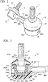
- FIG. 2 is a perspective view of the stabilizer link 11 of the embodiment of the present invention viewed obliquely from above.
- FIG. 3 is a front view including a partial cross-sectional view of a ball joint 13 of a pair of ball joints 13 that are components of the stabilizer link 11 of the embodiment of the present invention, to which a link protector 29 is attached.
- FIG. 4 is a front view of a ball joint 13 of the ball joints 13 that are components of the stabilizer link 11 of the embodiment of the present invention, to which the link protector 29 is not attached.
- wheels W are mounted on a vehicle body (not shown) of the vehicle via suspensions 15.
- the suspension 15 includes, for example, a coil spring 15a and a shock absorber 15b in order to absorb and reduce shocks and vibrations transmitted to the vehicle body from the road surface via the wheel W.
- the left and right suspensions 15 are linked via a stabilizer 17 configured of a substantially U-shaped spring steel rod or the like.
- the stabilizer 17 includes a torsion bar 17a extending between the left and right wheels W, and a pair of arms 17b extending in a bent manner from both ends of the torsion bar 17a.
- a stabilizer with a stabilizer link is configured of the stabilizer 17 and the stabilizer link 11.
- one ball joint 13 of the pair of ball joints 13 is fastened and fixed to a bracket 15c of the shock absorber 15b through screw connection or the like.
- the other ball joint 13 thereof is fastened and fixed to an attachment portion 17c included in the arm 17b of the stabilizer 17 through screw connection or the like.
- the linking structure between the stabilizer 17 and the shock absorber 15b via the stabilizer link 11 is the same as each other with respect to the left and right wheels W.
- the stabilizer link 11 is configured by providing the ball joint 13 at each of two ends of a substantially columnar (rod-shaped) support bar 12 made of metal such as steel.
- each ball joint 13 is configured including a ball stud 21 made of metal such as steel, a ball seat 23 (a support member) made of resin, and a substantially bowl-shaped (a cylindrical shape with a bottom) housing 25 (a support member) made of metal such as steel.
- the side of the stabilizer link 11 on which the ball stud 21 is provided is referred to as the upper side of the stabilizer link 11, and the side of the stabilizer link 11 on which the housing 25 is provided is referred to as the lower side of the stabilizer link 11.
- the attitude of the stabilizer link 11 provided in the vehicle is different from the attitude thereof shown in FIGS. 3 and 4 , and as shown in FIG. 1 , the stabilizer link 11 is provided in the vehicle in an attitude such that the support bar 12 extends substantially in a vertical direction.
- the ball stud 21 is configured including a columnar stud portion 21a at one end thereof, and a substantially spherical ball portion 21b at the other end thereof. That is, the stud portion 21a is arranged to extend in an up-down direction, and the ball portion 21b is connected to the lower end of the stud portion 21a.
- the stud portion 21a and the ball portion 21b are connected together through welding.
- the stud portion 21a and the ball portion 21b may be integrally formed.
- the stud portion 21a of the ball stud 21 includes a flange 21a1 at a position between its ends.
- the flange 21a1 protrudes from the outer circumferential surface of the stud portion 21a.
- An annular dust cover 27 made of an elastic material such as rubber is attached to a gap in the up-down direction between the flange 21a1 of the stud portion 21a and a flange-shaped upper annular end 25a (an engagement portion) included in the housing 25, so as to cover the gap.
- the upper end of the dust cover 27 is disposed below the flange 21al on the outer circumferential surface of the stud portion 21a, and the lower end of the dust cover 27 is disposed on the upper surface of the upper annular end 25a.
- an annular bulged attachment portion 27a is integrally formed at the lower end side of the dust cover 27. That is, the attachment portion 27a slightly protruding upward is provided at the radially inner end of the lower end portion of the dust cover 27 on the entire circumference of the dust cover 27.
- the attachment portion 27a of the dust cover 27 is sandwiched and fixed between a flange-shaped annular end 23b included in the ball seat 23 and the upper annular end 25a included in the housing 25.
- the fixing structure on the lower end side of the dust cover 27 is equivalent to the structure shown in Japanese Unexamined Patent Application, First Publication No. 2016-151303 (refer to, for example, FIG. 3 ).
- the dust cover 27 has functions of preventing the intrusion of rainwater, dust and the like into the ball joint 13 (in particular, the connection portion between the ball portion 21b of the ball stud 21 and the ball seat 23).
- the ball seat 23 has functions of rotatably accommodating and supporting the outer circumferential side surface of the ball portion 21b of the ball stud 21.
- the ball seat 23 of this embodiment is formed in a cylindrical shape (for example, a circular-cylindrical shape) with a bottom whose central axis extends in the up-down direction, and the annular end 23b protrudes outward in a radial direction from the upper end of the side wall of the ball seat 23.
- four bosses 23a extending downward are integrally formed in the bottom portion of the ball seat 23 such that the number of the bosses 23a corresponds to the number of four through-holes 25c of the housing 25 described later.
- the housing 25 is formed in a cylindrical shape (for example, circular-cylindrical shape) with a bottom whose central axis extends in the up-down direction and is provided to cover the outer circumferential side surface (the outer circumferential surface of the side wall) and the bottom surface of the ball seat 23 made of resin.
- the upper annular end 25a protrudes outward in the radial direction from the upper end of the side wall of the housing 25.
- the housing 25 made of metal has functions of protecting the ball joint 13 including the ball seat 23 made of resin.
- the combination of the ball seat 23 and the housing 25 corresponds to the "support member" of the present invention.
- the four through-holes 25c are opened at equal intervals in a bottom portion 25b of the housing 25. That is, the four through-holes 25c penetrating the bottom portion 25b in the thickness direction thereof are provided at equivalent intervals in a direction around the axis of the stud portion 21a.
- These four through-holes 25c are used to fix the ball seat 23 to the housing 25. That is, in a state where the bosses 23a of the ball seat 23 are penetrated through the through-holes 25c of the housing 25, the heat caulking is applied to penetrated ends 23a1 (lower ends) of the bosses 23a.
- the ball seat 23 is fixed to the housing 25 through this heat caulking.
- One end 12a of the support bar 12 is connected to a circumferential side portion 25d (the side wall) of the housing 25 through welding. Not limited to the welding connection, the one end 12a of the support bar 12 may be connected to the side wall of the housing 25 using, for example, a fastening member (a bolt or the like).
- the penetrated ends 23a1 of the bosses 23a of the ball seat 23 are exposed outward (downward in FIGS. 3 and 4 ) from the through-holes 25c of the housing 25. Therefore, depending on the mounting state such as the orientation of the housing 25, a case is assumed that flying objects such as stones collide with the penetrated ends 23a1 of the bosses 23a. If the flying objects collide with the penetrated ends 23a1 of the bosses 23a, there is a concern that the ball joint function will be disturbed.
- the housing 25 of the ball joint 13 is attached with the link protector 29 of this embodiment.
- the link protector 29 of this embodiment corresponds to the "cover member" of the present invention.
- FIG. 5 is a perspective view of the link protector 29 of this embodiment viewed obliquely from above.
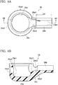
- FIG. 6A is a top view of the link protector 29 of this embodiment.
- FIG. 6B is a cross-sectional view taken along line 6B-6B shown in FIG. 6A .
- FIG. 6C is a front view of the link protector 29.
- FIG. 6D is a cross-sectional view taken along line 6D-6D shown in FIG. 6C .
- FIG. 6E is a side view of the link protector 29 viewed from the position of a holding portion.
- FIG. 7 is a perspective view of the ball joint 13 attached with the link protector 29 of this embodiment, viewed obliquely from above.
- the link protector 29 of this embodiment is configured including a main portion 29a having a substantially bowl shape (a cylindrical shape with a bottom), and a substantially gutter-shaped holding portion 29b.
- the "cylindrical shape with a bottom” of this embodiment includes a "bowl shape”.
- the link protector 29 is integrally formed through injection molding or the like of a synthetic resin.
- a synthetic resin for example, PA66-GF30 (PA66 with 30% to 50% by weight glass fiber / melting point: about 270°C) is preferably used in consideration of having thermoplasticity, satisfying predetermined strength requirements and the like.
- the link protector 29 may be suitably used for the resin material of the link protector 29, materials such as engineering plastics such as PEEK (polyetheretherketone), PA66 (Polyamide 66), PPS (Poly Phenylene Sulfide Resin) and POM (polyoxymethylene), super engineering plastics, FRP (Fiber Reinforced Plastics), GRP (glass reinforced plastic) and CFRP (Carbon Fiber Reinforced Plastics), other than PA66-GF30, may be suitably used. Further, the link protector 29 may be made of a material other than resin (for example, metal) as long as the link protector 29 can be appropriately elastically deformed.
- engineering plastics such as PEEK (polyetheretherketone), PA66 (Polyamide 66), PPS (Poly Phenylene Sulfide Resin) and POM (polyoxymethylene
- FRP Fiber Reinforced Plastics
- GRP glass reinforced plastic
- CFRP Carbon Fiber Reinforced Plastics
- the substantially bowl-shaped main portion 29a of the link protector 29 includes a housing portion 29a1 having an inner diameter slightly greater than the outer diameter of the housing 25.
- the housing portion 29a1 is configured such that substantially the whole of the housing 25 is accommodated therein.
- a slight gap is provided between the housing 25 and the link protector 29. That is, a slight gap is provided between the outer circumferential surface of the side wall of the housing 25 and the inner circumferential surface of the side wall of the link protector 29, and a slight gap is provided between the outer surface (the lower surface) of the bottom portion of the housing 25 and the inner surface (the upper surface) of the bottom portion of the link protector 29.
- the gap in the up-down direction at the bottom portion is greater than the gap in the radial direction at the side wall.
- a reason for providing a slight gap between the housing 25 and the link protector 29 is to smoothly discharge water, which has entered the gap, outward of the link protector 29 in cooperation with a conical-shaped portion 29a3 and a through-hole 29a4 described later.
- a receiving portion 29a2 (a side wall-upper portion) configured of an annular step is formed in the side wall-upper portion of the main portion 29a of the link protector 29. That is, the receiving portion 29a2 is configured by the opening peripheral edge portion of the top surface of the cylindrical side wall of the link protector 29 being depressed downward.
- the upper annular end 25a included in the housing 25 is configured to right fit into the receiving portion 29a2. That is, the upward facing surface of the receiving portion 29a2 of the link protector 29 is engaged with the lower surface of the upper annular end 25a of the housing 25.
- the receiving portion 29a2 is not an essential component of this embodiment, but the upper portion of the side wall of the link protector 29 in which the receiving portion 29a2 is not formed may be engaged with the lower surface of the upper annular end 25a of the housing 25.
- the ball portion 21b of the ball stud 21 and the ball seat 23 that realize the ball joint function can be firmly protected by the double structure of the housing 25 and the link protector 29.
- the receiving portion 29a2 provided in the annular side wall-upper portion of the substantially bowl-shaped link protector 29 (refer to FIG. 5 ) is positioned to face, in the up-down direction, the annular lower end portion of the dust cover 27 as shown in FIG. 3 .
- the outer diameter of the main portion 29a of the link protector 29 is set to substantially the same dimension as the outer diameter of the dust cover 27. Therefore, according to the link protector 29, the effect of protecting the lower end portion of the dust cover 27 can be expected.
- the annular side wall-upper portion of the main portion 29a may be in contact with or be close to the annular lower end portion of the dust cover 27.
- the conical-shaped portion 29a3 (a communication portion) whose diameter gradually decreases as it goes from the main portion 29a-side to the holding portion 29b-side thereof is formed in the joint portion between the main portion 29a and the holding portion 29b of the link protector 29.
- the angle defined by the cone of the conical-shaped portion 29a3 is not particularly limited, but an appropriate angle of, for example, 30° to 60° is set therefor.
- the conical-shaped portion 29a3 has functions of smoothly discharging the water outward of the link protector 29.
- the conical-shaped portion 29a3 has functions of securing the rigidity of the joint portion between the main portion 29a and the holding portion 29b of the link protector 29.
- the circular through-hole 29a4 is opened at a portion of the main portion 29a of the link protector 29 facing the conical-shaped portion 29a3. That is, the through-hole 29a4 is provided in the side wall of the main portion 29a opposite to the conical-shaped portion 29a3 in the radial direction of the main portion 29a.
- the inner diameter of the through-hole 29a4 is not particularly limited, but an appropriate dimension of, for example, 0.3 to 0.4 times the outer diameter of the main portion 29a is set therefor.
- the stabilizer link 11 of this embodiment is provided in the vehicle in an attitude in which the support bar 12 extends in substantially the vertical direction (refer to FIG. 1 ).
- the link protector 29 of this embodiment is provided on the lower end side of the support bar 12, the through-hole 29a4 may be provided in a portion of the side wall of the main portion 29a facing downward in a state where the stabilizer link 11 is provided in the vehicle. In this case, the water that has entered the inside of the main portion 29a can be easily discharged through the through-hole 29a4.
- the substantially gutter-shaped holding portion 29b of the link protector 29 is connected to the side wall of the main portion 29a in which the conical-shaped portion 29a3 is formed, and radially extends from the main portion 29a.
- the holding portion 29b has a substantially gutter shape obtained by cutting out and removing a part of a cylinder extending in the axial direction thereof from the cylinder.
- the inner diameter Dgr of the holding portion 29b (refer to FIG. 6E ) is set to be equal to or slightly less than the outer diameter Dsb of the support bar 12 (refer to FIG. 7 ).
- the inner diameter Dgr of the holding portion 29b refers to the distance between inner surfaces of the holding portion 29b facing each other in the opposing direction (the left-right direction in FIG. 6E ) of a pair of cutout ends 29b1 of the holding portion 29b.
- the holding portion 29b is formed in a C-shape opening upward when viewed in the axial direction thereof.
- a gap D1 between the pair of cutout ends 29b1 of the substantially gutter-shaped holding portion 29b of the link protector 29 is set to be slightly less than the inner diameter Dgr of the holding portion 29b.
- the gap D1 is set in consideration of that the angle ⁇ (refer to FIG. 6E ) defined by the pointing directions (the projecting directions) of the pair of cutout ends 29b1 with respect to tangent of the outer circumferential surface of the support bar 12 exceeds about 90° (preferably 120°) when the outer circumferential surface of the support bar 12 is in contact with the pair of cutout ends 29b1.
- the holding portion 29b is configured to be elastically deformable such that the distance between the pair of cutout ends 29b1 can be increased.
- the gap D1 is set to be less than the inner diameter Dgr of the holding portion 29b, when the support bar 12 is pushed and fitted into the holding portion 29b, it is necessary to extend the gap D1 of the pair of cutout ends 29b1 to about the outer diameter Dsb of the support bar 12.
- each of the pair of cutout ends 29b1 has a tapered shape in the transverse cross-section thereof.
- the thickness of the pair of cutout ends 29b1 is less than the thickness of the general portion of the holding portion 29b other than the cutout ends 29b1.
- the tips of the pair of the cutout ends 29b1 are subjected to rounding work for eliminating corners.
- the tips of the pair of cutout ends 29b1 are portions that contact the outer circumferential surface of the support bar 12 when the support bar 12 is pushed and fitted into the holding portion 29b.
- the holding portion 29b is elastically deformable, when the pair of cutout ends 29b1 of the holding portion 29b is pushed toward the outer circumferential surface of the support bar 12, the distance between the pair of cutout ends 29b1 is increased, and the support bar 12 is inserted into the inside of the holding portion 29b. Then, since the pair of cutout ends 29b1 approach each other through the restoration deformation of the holding portion 29b, the holding portion 29b can properly hold the support bar 12, and the link protector 29 is arranged on one end side of the support bar 12.
- the axial length Lgr (refer to FIG. 6A ) of the holding portion 29b is set to about 2 to 3 times the outer diameter Dsb (refer to FIG. 7 ) of the support bar 12.
- a diameter-expanded portion 29b2 is provided at a portion of the holding portion 29b adjacent to the conical-shaped portion 29a3 of the main portion 29a.
- the diameter-expanded portion 29b2 is set to be slightly greater than the inner diameter Dgr (refer to FIG. 6E ) of the holding portion 29b. Since the diameter-expanded portion 29b2 is formed, a gap is provided between the holding portion 29b and the support bar 12.
- the diameter-expanded portion 29b2 has functions of smoothly discharging the water outward of the link protector 29 in cooperation with the conical-shaped portion 29a3, the through-hole 29a4, and a cutout 29b3 described below.
- the cutout 29b3 is provided in the vicinity of the diameter-expanded portion 29b2 of the holding portion 29b.
- the cutout 29b3 is formed by cutting out and removing a part in the vicinity of the diameter-expanded portion 29b2 from the holding portion 29b in an arc shape.
- the dimension in the depth direction of the cutout 29b3 is set to be shallower than the center of the support bar 12. That is, the lower end of the cutout 29b3 is positioned above the central axis of the support bar 12 in the up-down direction.
- a strong bending stress may occur in the joint portion (corresponding to "the connection portion connecting the side wall of the main portion and the holding portion" of the present invention) between the main portion 29a and the holding portion 29b of the link protector 29.
- the cutout 29b3 has functions of alleviating the bending stress generated in the process of pushing and fitting the support bar 12 into the holding portion 29b.
- the cutout 29b3 has functions of smoothly discharging this water outward of the link protector 29 in cooperation with the conical-shaped portion 29a3, the through-hole 29a4 and the diameter-expanded portion 29b2.
- the conical-shaped portion 29a3, the through-hole 29a4, the diameter-expanded portion 29b2 and the cutout 29b3 correspond to the "drainage mechanism" of the present invention. Further, the cutout 29b3 may not be formed.
- a beam-shaped reinforcement portion 29c that increases the mechanical strength of the joint portion between the main portion 29a and the holding portion 29b of the link protector 29 is provided on the back side (the lower side) of the diameter-expanded portion 29b2 of the holding portion 29b.
- the angle and the thickness dimension of the reinforcement portion 29c may be set to appropriate values depending on the strength required for the joint portion between the main portion 29a and the holding portion 29b.
- the reinforcement portion 29c has functions of bearing an external force applied to the joint portion in the process of pushing and fitting the support bar 12 into the holding portion 29b.
- the cutout 29b3 and the reinforcement portion 29c together receive the bending stress generated in the process of pushing and fitting the support bar 12 into the holding portion 29b, whereby the required load capacity for the joint portion between the main portion 29a and the holding portion 29b of the link protector 29 can be secured.
- FIG. 8 is a perspective view of the link protector 31 of the modification viewed obliquely from above.
- FIG. 9A is a top view of the link protector 31 of the modification.
- FIG. 9B is a cross-sectional view taken along line 9B-9B shown in FIG. 9A .
- the configuration of the link protector 29 of the above-described embodiment and the configuration of the link protector 31 of the modification have common parts. Accordingly, in order to avoid duplication of description, the common parts are attached with the same reference signs, the description thereof is omitted, and the description will be made focusing on differences between the above-described embodiment and the modification.
- the first difference is that in the link protector 31 of the modification, as shown in FIGS. 8 , 9A and 9B , a protection wall 33 is provided in the side wall-upper portion of the main portion 29a.
- the protection wall 33 includes a flat portion 33a extending in a substantially arc shape continuously with the side wall-upper portion of the main portion 29a, and a straight wall 33b vertically erecting from the outer peripheral edge of the flat portion 33a.
- the circumferential side surface of the dust cover 27 on the side thereof in which the protection wall 33 is positioned can be protected from disturbances such as collision of flying objects.
- a recess 35 configured of curved surfaces is provided in a portion of the side wall of the main portion 29a adjacent to the conical-shaped portion 29a3.
- the recess 35 is formed at an inner portion of the conical-shaped portion 29a3 in the inner surface of the side wall of the main portion 29a in the radial direction of the main portion 29a and is recessed outward in the radial direction.
- a first aspect of the present invention is the stabilizer link 11 for linking the suspension 15 and the stabilizer 17 provided in the vehicle, the stabilizer link 11 including: the support bar 12; and the pair of ball joints 13 provided at two ends of the support bar 12.
- Each of the pair of ball joints 13 includes: the ball stud 21 including the stud portion 21a and the ball portion 21b, and the ball seat 23 and the housing 25 (the support member) which rotatably supports the ball portion 21b of the ball stud 21 and to which the support bar 12 is connected.
- the link protector 29 or 31 includes: the main portion 29a having a cylindrical shape with a bottom and covering the ball seat 23 and the housing 25, the drainage mechanism (the conical-shaped portion 29a3, the through-hole 29a4, the diameter-expanded portion 29b2, and the cutout 29b3) for discharging water that has entered the gap between the housing 25 and the link protector 29 or 31, and the holding portion 29b holding the support bar 12.
- the holding portion 29b holds the support bar 12, whereby the main portion 29a of the link protector 29 or 31 is attached to cover the ball seat 23 and the housing 25.
- the link protector 29 of the stabilizer link 11 is provided with the main portion 29a having a cylindrical shape with a bottom and covering at least one of a pair of support members (the combinations of the ball seat 23 and the housing 25), and thus the main portion 29a covering the support member can protect the support member (including the heat caulked portion applied to the penetrated end 23a1 of the boss 23a of the ball seat 23) from collision of flying objects.
- the stabilizer link 11 that limits the ball joint function from being disturbed due to disturbance such as collision of the flying objects.
- the link protector 29 or 31 is provided with the drainage mechanism (the conical-shaped portion 29a3, the through-hole 29a4, the diameter-expanded portion 29b2, and the cutout 29b3) for discharging water that has entered the gap between the housing 25 and the link protector 29 or 31, a situation where the entered water intrudes inside the ball seat 23 or into a gap between the ball seat 23 and the housing 25 can be prevented in advance.
- a second aspect of the present invention is that in the stabilizer link 11 of the first aspect, as shown in FIG. 5 , the drainage mechanism includes: the through-hole 29a4 provided in the side wall of the main portion 29a of the link protector 29 or 31, the diameter-expanded portion 29b2 provided on the inner side wall of the holding portion 29b and allowing a gap to be provided between the holding portion 29b and the support bar 12, and the conical-shaped portion 29a3 (a communication portion) provided to allow the inside of the main portion 29a and the gap to communicate with each other.
- the conical-shaped portion 29a3, the through-hole 29a4 and the diameter-expanded portion 29b2 can cooperate to smoothly discharge the water outward of the link protector 29 or 31.
- a third aspect of the present invention is that in the stabilizer link 11 of the second aspect, the through-hole 29a4 is provided in the side wall of the main portion 29a facing the conical-shaped portion 29a3.
- the through-hole 29a4 and the conical-shaped portion 29a3 face each other, water that has entered the inside of the main portion 29a through, for example, the conical-shaped portion 29a3 can be smoothly discharged outward of the link protector 29 through the through-hole 29a4.
- a fourth aspect of the present invention is that in the stabilizer link 11 of the second or third aspect, the cutout 29b3 obtained by cutting out a part of the inner side wall of the holding portion 29b is provided in the vicinity of the diameter-expanded portion 29b2 of the holding portion 29b.
- the cutout 29b3 relieves the bending stress generated in the process of pushing and fitting the support bar 12 into the holding portion 29b, and when water enters the gap between the housing 25 and the link protector 29, the cutout 29b3 can smoothly discharge the water outward of the link protector 29 in cooperation with the conical-shaped portion 29a3, the through-hole 29a4 and the diameter-expanded portion 29b2.
- a fifth aspect of the present invention is that in the stabilizer link 11 of one of the first to fourth aspects, a joint portion (a connection portion) between the side wall of the main portion 29a and the holding portion 29b of the link protector 29 or 31 is provided with the reinforcement portion 29c that increases the mechanical strength of the joint portion (the connection portion).
- the reinforcement portion 29c receives the external force applied to the joint portion (the connection portion) in the process of pushing and fitting the support bar 12 into the holding portion 29b, and thus the required load capacity for the joint portion (the connection portion) between the main portion 29a and the holding portion 29b of the link protector 29 can be secured.
- a sixth aspect of the present invention is that in the stabilizer link 11 of one of the first to fifth aspects, the ball joint 13 is attached with the dust cover 27 for isolating the ball portion 21b from external environment, and the annular side wall-upper portion of the main portion 29a is in contact with or close to the annular lower end of the dust cover 27.
- the lower end portion of the dust cover 27 can be protected by the main portion 29a of the link protector 29 or 31.
- a seventh aspect of the present invention is that in the stabilizer link 11 of one of the first to sixth aspects, the housing 25 (the support member) is provided with the upper annular end 25a (the engagement portion) engaged with the annular receiving portion 29a2 (the side wall-upper portion) of the main portion 29a.
- the main portion 29a can be prevented from moving upward relative to the housing 25, and the gap between the lower surface of the bottom portion of the housing 25 and the upper surface of the bottom portion of the main portion 29a can be appropriately maintained. Therefore, it is possible to prevent the heat caulked portion of the penetrated end 23a1 from breaking or to prevent that the housing 25 cannot properly hold the ball seat 23, due to collision of the upper surface of the bottom portion of the main portion 29a with the lower surface of the bottom portion of the housing 25.
- An eighth aspect of the present invention is a stabilizer with a stabilizer link, including: the stabilizer 17; and the stabilizer link 11 of one of the first to seventh aspects, which is connected to the stabilizer 17.
- the stabilizer 17 with the stabilizer link 11 can be obtained, which can limit the ball joint function from being disturbed by the collision or the like of the flying objects.
- the stabilizer link 11 of the embodiment of the present invention an example is described in which the four through-holes 25c are opened in the bottom portion of the housing 25, and the four bosses 23a whose number corresponds to the number of the through-holes 25c of the housing 25 are integrally formed in the bottom portion of the ball seat 23, but the present invention is not limited to this example.
- the number of the through-holes 25c and the number of the bosses 23a may be any numbers as long as the numbers correspond to each other.
- the present invention is not limited to this example.
- the housing 25 made of metal as a member constituting the support member may be omitted.
- the shape of the ball seat 23 made of resin may be configured to serve as a housing.
- the ball seat 23 and the support bar 12 may be connected to each other using a fastening member such as a bolt or a bracket.
- the link protector 29 or 31 is provided in one of the pair of the support members (composed of the combinations of the ball seat 23 and the housing 25), but the present invention is not limited to this example.
- Either one of the link protectors 29 and 31 may be provided in each of the pair of support members, or a configuration in which the link protectors 29 and 31 are provided in the pair of support members, respectively, may be adopted.
- At least one end of the support bar may be provided with the link protector of the present invention.
- the holding portion 29b of the above-described embodiment has a gutter shape in which a part of a cylinder is cut out in the axial direction of the cylinder, but the present invention is not limited to this.
- the holding portion may be composed of a plurality of C-ring-shaped members disposed at intervals in the axial direction of the support bar 12.
- the holding portion 29b of the above-described embodiment has a gutter shape that opens upward, but in order to prevent detachment of the holding portion 29b from the support bar 12, a configuration may be adopted in which a cover member covering the opening of the gutter shape or a member preventing an increase of the separation of the pair of cutout ends 29b1 is provided after the holding portion 29b holds the support bar 12.
- the cover member or the like may be pivotably connected to the holding portion 29b using a hinge or the like.
Landscapes
- Engineering & Computer Science (AREA)
- Mechanical Engineering (AREA)
- General Engineering & Computer Science (AREA)
- Vehicle Body Suspensions (AREA)
- Pivots And Pivotal Connections (AREA)
Abstract
Description
- The present invention relates to a stabilizer link for linking a suspension and a stabilizer provided in a vehicle, and the stabilizer with the stabilizer link.
- Priority is claimed on Japanese Patent Application No.
2016-215636, filed November 2, 2016 - A vehicle is provided with a suspension that absorbs and reduces shocks and vibrations transmitted to a vehicle body from the road surface via wheels, and a stabilizer for increasing the roll rigidity of the vehicle body. In order to link the suspension and the stabilizer, a rod-shaped member called stabilizer link is used for the vehicle. As shown in, for example, Patent Document 1, the stabilizer link is configured including a support bar and ball joints provided at both ends of the support bar.
- The ball joint of Patent Document 1 is configured of a ball stud including a stud portion and a ball portion, a ball seat provided at each of ends of the support bar and made of resin rotatably accommodating the ball portion of the ball stud, and a housing made of steel and provided so as to cover the outer surface of the ball seat. The ball seat made of resin is fixed by heat caulking to the housing made of steel. The ball joint is configured of the ball stud and the ball seat.
- Further, Patent Document 2 discloses a stabilizer link provided with a protection cap that protects a ball stud.
-
- [Patent Document 1] Japanese Unexamined Patent Application, First Publication No.
2016-151303 - [Patent Document 2] Published Japanese Translation No.
2008-504495 of the PCT - Specifically, in the stabilizer link of Patent Document 1, bosses integrally formed so as to protrude from the ball seat made of resin are penetrated through through-holes provided in the housing made of steel, and the penetrated ends of the bosses are subjected to the heat caulking, whereby the ball seat is fixed to the housing. The penetrated ends of the bosses are exposed outward from the through-holes of the housing.
- A case is assumed that flying objects such as stones collide with the housing of the stabilizer link of Patent Document 1 depending on the mounting state thereof. If the flying objects collide with the penetrated ends of the bosses, there is a concern that the ball joint function will be disturbed.
- The present invention has been made in view of the above circumstances, and an object thereof is to provide a stabilizer link and a stabilizer with a stabilizer link, which can limit the ball joint function from being disturbed due to disturbance such as collision of the flying objects.
- In order to solve the above problems, one aspect of the present invention is a stabilizer link for linking a suspension and a stabilizer provided in a vehicle, the stabilizer link including: a support bar; and a pair of ball joints provided at both ends of the support bar, wherein each of the pair of ball joints includes: a ball stud including a stud portion and a ball portion, and a support member which rotatably supports the ball portion of the ball stud and to which the support bar is connected, at least one end of the support bar is provided with a link protector, and the link protector includes: a main portion having a cylindrical shape with a bottom and covering the support member, a drainage mechanism for discharging water that has entered a gap between the support member and the link protector, and a holding portion holding the support bar.
- The link protector of the stabilizer link of the above aspect of the present invention is provided with the main portion having a cylindrical shape with a bottom and covering at least one of the pair of the support members. The link protector further includes the drainage mechanism for discharging water that has entered the gap between the support member and the link protector, and the holding portion that holds the support bar. The holding portion holds the support bar, whereby the main portion of the link protector is attached to cover the support member.
- According to the above aspect of the present invention, the link protector of the stabilizer link is provided with the main portion having a cylindrical shape with a bottom and covering at least one of the pair of the support members, and the main portion covering the support member protects the support member from collisions of the flying objects. As a result, the stabilizer link that limits the ball joint function from being disturbed due to disturbances such as the collisions of the flying objects can be obtained. Also, since the link protector is provided with the drainage mechanism for discharging water that has entered the gap between the support member and the link protector, a situation where the entered water intrudes inside the support member can be prevented in advance.
- According to the above aspect of the present invention, it is possible to obtain a stabilizer link and a stabilizer with a stabilizer link, which can limit the ball joint function from being disturbed due to disturbance such as collision of the flying objects.
-
-
FIG. 1 is a perspective view showing how a stabilizer link is mounted on a vehicle. -
FIG. 2 is a perspective view of a stabilizer link of an embodiment of the present invention viewed obliquely from above. -
FIG. 3 is a front view including a partial cross-sectional view of a ball joint of ball joints that are components of the stabilizer link of the embodiment of the present invention, to which a link protector is attached. -
FIG. 4 is a front view of a ball joint of the ball joints that are components of the stabilizer link of the embodiment of the present invention, to which no link protector is attached. -
FIG. 5 is a perspective view of the link protector of the embodiment of the present invention viewed obliquely from above. -
FIG. 6A is a top view of the link protector of the embodiment of the present invention. -
FIG. 6B is a cross-sectional view taken alongline 6B-6B shown inFIG. 6A . -
FIG. 6C is a front view of the link protector of the embodiment of the present invention. -
FIG. 6D is a cross-sectional view taken alongline 6D-6D shown inFIG. 6C . -
FIG. 6E is a side view of the link protector viewed from the position of a holding portion. -
FIG. 7 is a perspective view of the ball joint attached with the link protector of the embodiment of the present invention, viewed obliquely from above. -
FIG. 8 is a perspective view of a link protector of a modification viewed obliquely from above. -
FIG. 9A is a top view of the link protector of the modification. -
FIG. 9B is a cross-sectional view taken alongline 9B-9B shown inFIG. 9A . - Hereinafter, a stabilizer link of an embodiment of the present invention will be described in detail with reference to the drawings as appropriate.
- Note that, in the drawings described below, in principle, the same reference signs are attached to members having the same functions or to members having functions corresponding to each other. Further, for convenience of description, the size and shape of members may be schematically shown through deformation or enlargement.
- First, the configuration of a
stabilizer link 11 and the surroundings thereof of the embodiment of the present invention will be described using an example in which thestabilizer link 11 is mounted on a vehicle (not shown).FIG. 1 is a perspective view showing how thestabilizer link 11 of the embodiment of the present invention is mounted on the vehicle.FIG. 2 is a perspective view of thestabilizer link 11 of the embodiment of the present invention viewed obliquely from above.FIG. 3 is a front view including a partial cross-sectional view of aball joint 13 of a pair ofball joints 13 that are components of thestabilizer link 11 of the embodiment of the present invention, to which alink protector 29 is attached.FIG. 4 is a front view of aball joint 13 of theball joints 13 that are components of thestabilizer link 11 of the embodiment of the present invention, to which thelink protector 29 is not attached. - As shown in
FIG. 1 , wheels W are mounted on a vehicle body (not shown) of the vehicle viasuspensions 15. Thesuspension 15 includes, for example, acoil spring 15a and ashock absorber 15b in order to absorb and reduce shocks and vibrations transmitted to the vehicle body from the road surface via the wheel W. - As shown in
FIG. 1 , the left andright suspensions 15 are linked via a stabilizer 17 configured of a substantially U-shaped spring steel rod or the like. In order to increase the roll rigidity (resistance to torsional deformation) of the vehicle body and to limit the rolling of the vehicle, the stabilizer 17 includes atorsion bar 17a extending between the left and right wheels W, and a pair ofarms 17b extending in a bent manner from both ends of thetorsion bar 17a. - The stabilizer 17 and the
shock absorber 15b supporting the wheel W are linked via thestabilizer link 11. A stabilizer with a stabilizer link is configured of the stabilizer 17 and thestabilizer link 11. Specifically, as shown inFIG. 1 , one ball joint 13 of the pair of ball joints 13 is fastened and fixed to abracket 15c of theshock absorber 15b through screw connection or the like. Further, as shown inFIG. 1 , the other ball joint 13 thereof is fastened and fixed to anattachment portion 17c included in thearm 17b of the stabilizer 17 through screw connection or the like. - As shown in
FIG. 1 , the linking structure between the stabilizer 17 and theshock absorber 15b via thestabilizer link 11 is the same as each other with respect to the left and right wheels W. - As shown in
FIGS. 1 and2 , thestabilizer link 11 is configured by providing the ball joint 13 at each of two ends of a substantially columnar (rod-shaped)support bar 12 made of metal such as steel. - As shown in
FIG. 3 , each ball joint 13 is configured including aball stud 21 made of metal such as steel, a ball seat 23 (a support member) made of resin, and a substantially bowl-shaped (a cylindrical shape with a bottom) housing 25 (a support member) made of metal such as steel. - Hereinafter, for convenience, in
FIGS. 3 and4 , the side of thestabilizer link 11 on which theball stud 21 is provided is referred to as the upper side of thestabilizer link 11, and the side of thestabilizer link 11 on which thehousing 25 is provided is referred to as the lower side of thestabilizer link 11. The attitude of thestabilizer link 11 provided in the vehicle is different from the attitude thereof shown inFIGS. 3 and4 , and as shown inFIG. 1 , thestabilizer link 11 is provided in the vehicle in an attitude such that thesupport bar 12 extends substantially in a vertical direction. - As shown in
FIG. 3 , theball stud 21 is configured including acolumnar stud portion 21a at one end thereof, and a substantiallyspherical ball portion 21b at the other end thereof. That is, thestud portion 21a is arranged to extend in an up-down direction, and theball portion 21b is connected to the lower end of thestud portion 21a. Thestud portion 21a and theball portion 21b are connected together through welding. Thestud portion 21a and theball portion 21b may be integrally formed. - As shown in
FIG. 3 , thestud portion 21a of theball stud 21 includes a flange 21a1 at a position between its ends. The flange 21a1 protrudes from the outer circumferential surface of thestud portion 21a. Anannular dust cover 27 made of an elastic material such as rubber is attached to a gap in the up-down direction between the flange 21a1 of thestud portion 21a and a flange-shaped upperannular end 25a (an engagement portion) included in thehousing 25, so as to cover the gap. The upper end of thedust cover 27 is disposed below the flange 21al on the outer circumferential surface of thestud portion 21a, and the lower end of thedust cover 27 is disposed on the upper surface of the upperannular end 25a. - As shown in
FIG. 3 , an annular bulgedattachment portion 27a is integrally formed at the lower end side of thedust cover 27. That is, theattachment portion 27a slightly protruding upward is provided at the radially inner end of the lower end portion of thedust cover 27 on the entire circumference of thedust cover 27. Theattachment portion 27a of thedust cover 27 is sandwiched and fixed between a flange-shapedannular end 23b included in theball seat 23 and the upperannular end 25a included in thehousing 25. The fixing structure on the lower end side of thedust cover 27 is equivalent to the structure shown in Japanese Unexamined Patent Application, First Publication No.2016-151303 FIG. 3 ). Thedust cover 27 has functions of preventing the intrusion of rainwater, dust and the like into the ball joint 13 (in particular, the connection portion between theball portion 21b of theball stud 21 and the ball seat 23). - As shown in
FIG. 3 , theball seat 23 has functions of rotatably accommodating and supporting the outer circumferential side surface of theball portion 21b of theball stud 21. Theball seat 23 of this embodiment is formed in a cylindrical shape (for example, a circular-cylindrical shape) with a bottom whose central axis extends in the up-down direction, and theannular end 23b protrudes outward in a radial direction from the upper end of the side wall of theball seat 23. As shown inFIG. 3 , four bosses 23a extending downward are integrally formed in the bottom portion of theball seat 23 such that the number of the bosses 23a corresponds to the number of four through-holes 25c of thehousing 25 described later. - As shown in
FIG. 3 , thehousing 25 is formed in a cylindrical shape (for example, circular-cylindrical shape) with a bottom whose central axis extends in the up-down direction and is provided to cover the outer circumferential side surface (the outer circumferential surface of the side wall) and the bottom surface of theball seat 23 made of resin. The upperannular end 25a protrudes outward in the radial direction from the upper end of the side wall of thehousing 25. Thehousing 25 made of metal has functions of protecting the ball joint 13 including theball seat 23 made of resin. The combination of theball seat 23 and thehousing 25 corresponds to the "support member" of the present invention. - As shown in
FIG. 3 , the four through-holes 25c are opened at equal intervals in abottom portion 25b of thehousing 25. That is, the four through-holes 25c penetrating thebottom portion 25b in the thickness direction thereof are provided at equivalent intervals in a direction around the axis of thestud portion 21a. These four through-holes 25c are used to fix theball seat 23 to thehousing 25. That is, in a state where the bosses 23a of theball seat 23 are penetrated through the through-holes 25c of thehousing 25, the heat caulking is applied to penetrated ends 23a1 (lower ends) of the bosses 23a. Theball seat 23 is fixed to thehousing 25 through this heat caulking. Oneend 12a of thesupport bar 12 is connected to acircumferential side portion 25d (the side wall) of thehousing 25 through welding. Not limited to the welding connection, the oneend 12a of thesupport bar 12 may be connected to the side wall of thehousing 25 using, for example, a fastening member (a bolt or the like). - As shown in
FIGS. 3 and4 , the penetrated ends 23a1 of the bosses 23a of theball seat 23 are exposed outward (downward inFIGS. 3 and4 ) from the through-holes 25c of thehousing 25. Therefore, depending on the mounting state such as the orientation of thehousing 25, a case is assumed that flying objects such as stones collide with the penetrated ends 23a1 of the bosses 23a. If the flying objects collide with the penetrated ends 23a1 of the bosses 23a, there is a concern that the ball joint function will be disturbed. For example, there may be a case where the heat caulked portion of the penetrated end 23a1 is broken and thehousing 25 cannot properly hold theball seat 23, or a case where thehousing 25 or theball seat 23 is deformed and the smooth rotation of theball portion 21b of theball stud 21 is disturbed. - Accordingly, in order to protect the penetrated ends 23a1 of the bosses 23a from the collision of the flying objects such as stones, as shown in
FIGS. 2 and 3 , thehousing 25 of the ball joint 13 is attached with thelink protector 29 of this embodiment. Thelink protector 29 of this embodiment corresponds to the "cover member" of the present invention. - Next, the
link protector 29 of this embodiment will be described with reference toFIGS. 3 ,5 ,6A to 6D and7 .FIG. 5 is a perspective view of thelink protector 29 of this embodiment viewed obliquely from above.FIG. 6A is a top view of thelink protector 29 of this embodiment.FIG. 6B is a cross-sectional view taken alongline 6B-6B shown inFIG. 6A .FIG. 6C is a front view of thelink protector 29.FIG. 6D is a cross-sectional view taken alongline 6D-6D shown inFIG. 6C .FIG. 6E is a side view of thelink protector 29 viewed from the position of a holding portion.FIG. 7 is a perspective view of the ball joint 13 attached with thelink protector 29 of this embodiment, viewed obliquely from above. - As shown in
FIG. 5 , thelink protector 29 of this embodiment is configured including amain portion 29a having a substantially bowl shape (a cylindrical shape with a bottom), and a substantially gutter-shapedholding portion 29b. In addition, the "cylindrical shape with a bottom" of this embodiment includes a "bowl shape". - The
link protector 29 is integrally formed through injection molding or the like of a synthetic resin. For the resin material of thelink protector 29, for example, PA66-GF30 (PA66 with 30% to 50% by weight glass fiber / melting point: about 270°C) is preferably used in consideration of having thermoplasticity, satisfying predetermined strength requirements and the like. However, for the resin material of thelink protector 29, materials such as engineering plastics such as PEEK (polyetheretherketone), PA66 (Polyamide 66), PPS (Poly Phenylene Sulfide Resin) and POM (polyoxymethylene), super engineering plastics, FRP (Fiber Reinforced Plastics), GRP (glass reinforced plastic) and CFRP (Carbon Fiber Reinforced Plastics), other than PA66-GF30, may be suitably used. Further, thelink protector 29 may be made of a material other than resin (for example, metal) as long as thelink protector 29 can be appropriately elastically deformed. - As shown in
FIGS. 3 and5 , the substantially bowl-shapedmain portion 29a of thelink protector 29 includes a housing portion 29a1 having an inner diameter slightly greater than the outer diameter of thehousing 25. The housing portion 29a1 is configured such that substantially the whole of thehousing 25 is accommodated therein. A slight gap is provided between thehousing 25 and thelink protector 29. That is, a slight gap is provided between the outer circumferential surface of the side wall of thehousing 25 and the inner circumferential surface of the side wall of thelink protector 29, and a slight gap is provided between the outer surface (the lower surface) of the bottom portion of thehousing 25 and the inner surface (the upper surface) of the bottom portion of thelink protector 29. The gap in the up-down direction at the bottom portion is greater than the gap in the radial direction at the side wall. A reason for providing a slight gap between thehousing 25 and thelink protector 29 is to smoothly discharge water, which has entered the gap, outward of thelink protector 29 in cooperation with a conical-shaped portion 29a3 and a through-hole 29a4 described later. - As shown in
FIGS. 3 ,5 ,6A and 6B , a receiving portion 29a2 (a side wall-upper portion) configured of an annular step is formed in the side wall-upper portion of themain portion 29a of thelink protector 29. That is, the receiving portion 29a2 is configured by the opening peripheral edge portion of the top surface of the cylindrical side wall of thelink protector 29 being depressed downward. As shown inFIG. 3 , the upperannular end 25a included in thehousing 25 is configured to right fit into the receiving portion 29a2. That is, the upward facing surface of the receiving portion 29a2 of thelink protector 29 is engaged with the lower surface of the upperannular end 25a of thehousing 25. In addition, the receiving portion 29a2 is not an essential component of this embodiment, but the upper portion of the side wall of thelink protector 29 in which the receiving portion 29a2 is not formed may be engaged with the lower surface of the upperannular end 25a of thehousing 25. - As a result, the
ball portion 21b of theball stud 21 and theball seat 23 that realize the ball joint function can be firmly protected by the double structure of thehousing 25 and thelink protector 29. - The receiving portion 29a2 provided in the annular side wall-upper portion of the substantially bowl-shaped link protector 29 (refer to
FIG. 5 ) is positioned to face, in the up-down direction, the annular lower end portion of thedust cover 27 as shown inFIG. 3 . Further, as shown inFIG. 3 , the outer diameter of themain portion 29a of thelink protector 29 is set to substantially the same dimension as the outer diameter of thedust cover 27. Therefore, according to thelink protector 29, the effect of protecting the lower end portion of thedust cover 27 can be expected. In addition, the annular side wall-upper portion of themain portion 29a may be in contact with or be close to the annular lower end portion of thedust cover 27. - As shown in
FIGS. 5 ,6A and 6B , the conical-shaped portion 29a3 (a communication portion) whose diameter gradually decreases as it goes from themain portion 29a-side to the holdingportion 29b-side thereof is formed in the joint portion between themain portion 29a and the holdingportion 29b of thelink protector 29. The angle defined by the cone of the conical-shaped portion 29a3 is not particularly limited, but an appropriate angle of, for example, 30° to 60° is set therefor. When water enters the gap between thehousing 25 and thelink protector 29, the conical-shaped portion 29a3 has functions of smoothly discharging the water outward of thelink protector 29. In addition, the conical-shaped portion 29a3 has functions of securing the rigidity of the joint portion between themain portion 29a and the holdingportion 29b of thelink protector 29. - As shown in
FIGS. 5 ,6A and 6B , the circular through-hole 29a4 is opened at a portion of themain portion 29a of thelink protector 29 facing the conical-shaped portion 29a3. That is, the through-hole 29a4 is provided in the side wall of themain portion 29a opposite to the conical-shaped portion 29a3 in the radial direction of themain portion 29a. The inner diameter of the through-hole 29a4 is not particularly limited, but an appropriate dimension of, for example, 0.3 to 0.4 times the outer diameter of themain portion 29a is set therefor. When water enters the gap between thehousing 25 and thelink protector 29, the through-hole 29a4 has functions of smoothly discharging the water outward of thelink protector 29 in cooperation with the conical-shaped portion 29a3. - As described above, the
stabilizer link 11 of this embodiment is provided in the vehicle in an attitude in which thesupport bar 12 extends in substantially the vertical direction (refer toFIG. 1 ). If thelink protector 29 of this embodiment is provided on the lower end side of thesupport bar 12, the through-hole 29a4 may be provided in a portion of the side wall of themain portion 29a facing downward in a state where thestabilizer link 11 is provided in the vehicle. In this case, the water that has entered the inside of themain portion 29a can be easily discharged through the through-hole 29a4. - As shown in
FIG. 5 , the substantially gutter-shapedholding portion 29b of thelink protector 29 is connected to the side wall of themain portion 29a in which the conical-shaped portion 29a3 is formed, and radially extends from themain portion 29a. As shown inFIG. 5 , the holdingportion 29b has a substantially gutter shape obtained by cutting out and removing a part of a cylinder extending in the axial direction thereof from the cylinder. The inner diameter Dgr of the holdingportion 29b (refer toFIG. 6E ) is set to be equal to or slightly less than the outer diameter Dsb of the support bar 12 (refer toFIG. 7 ). The inner diameter Dgr of the holdingportion 29b refers to the distance between inner surfaces of the holdingportion 29b facing each other in the opposing direction (the left-right direction inFIG. 6E ) of a pair of cutout ends 29b1 of the holdingportion 29b. - The holding
portion 29b is formed in a C-shape opening upward when viewed in the axial direction thereof. - As shown in
FIG. 6E , a gap D1 between the pair of cutout ends 29b1 of the substantially gutter-shapedholding portion 29b of thelink protector 29 is set to be slightly less than the inner diameter Dgr of the holdingportion 29b. The gap D1 is set in consideration of that the angle θ (refer toFIG. 6E ) defined by the pointing directions (the projecting directions) of the pair of cutout ends 29b1 with respect to tangent of the outer circumferential surface of thesupport bar 12 exceeds about 90° (preferably 120°) when the outer circumferential surface of thesupport bar 12 is in contact with the pair of cutout ends 29b1. The holdingportion 29b is configured to be elastically deformable such that the distance between the pair of cutout ends 29b1 can be increased. - Since the gap D1 is set to be less than the inner diameter Dgr of the holding
portion 29b, when thesupport bar 12 is pushed and fitted into the holdingportion 29b, it is necessary to extend the gap D1 of the pair of cutout ends 29b1 to about the outer diameter Dsb of thesupport bar 12. - Accordingly, as shown in
FIG. 6E , each of the pair of cutout ends 29b1 has a tapered shape in the transverse cross-section thereof. In other words, the thickness of the pair of cutout ends 29b1 is less than the thickness of the general portion of the holdingportion 29b other than the cutout ends 29b1. Further, the tips of the pair of the cutout ends 29b1 are subjected to rounding work for eliminating corners. The tips of the pair of cutout ends 29b1 are portions that contact the outer circumferential surface of thesupport bar 12 when thesupport bar 12 is pushed and fitted into the holdingportion 29b. - Since the holding
portion 29b is elastically deformable, when the pair of cutout ends 29b1 of the holdingportion 29b is pushed toward the outer circumferential surface of thesupport bar 12, the distance between the pair of cutout ends 29b1 is increased, and thesupport bar 12 is inserted into the inside of the holdingportion 29b. Then, since the pair of cutout ends 29b1 approach each other through the restoration deformation of the holdingportion 29b, the holdingportion 29b can properly hold thesupport bar 12, and thelink protector 29 is arranged on one end side of thesupport bar 12. - According to the above configuration, the process of pushing and fitting the
support bar 12 into the holdingportion 29b can be smoothly and properly carried out. - The axial length Lgr (refer to
FIG. 6A ) of the holdingportion 29b is set to about 2 to 3 times the outer diameter Dsb (refer toFIG. 7 ) of thesupport bar 12. By setting in this manner, necessary and sufficient sizes of the holding force and the frictional force generated between the holdingportion 29b and thesupport bar 12 when the holdingportion 29b holds thesupport bar 12 can be secured. As a result, thelink protector 29 can be firmly attached to the ball joint 13 using the holding force and the frictional force generated by the holdingportion 29b firmly holding thesupport bar 12. - As shown in
FIGS. 5 ,6A and 6B , a diameter-expanded portion 29b2 is provided at a portion of the holdingportion 29b adjacent to the conical-shaped portion 29a3 of themain portion 29a. The diameter-expanded portion 29b2 is set to be slightly greater than the inner diameter Dgr (refer toFIG. 6E ) of the holdingportion 29b. Since the diameter-expanded portion 29b2 is formed, a gap is provided between the holdingportion 29b and thesupport bar 12. When water enters the gap between thehousing 25 and thelink protector 29, the diameter-expanded portion 29b2 has functions of smoothly discharging the water outward of thelink protector 29 in cooperation with the conical-shaped portion 29a3, the through-hole 29a4, and a cutout 29b3 described below. - As shown in
FIGS. 5 ,6B and6C , the cutout 29b3 is provided in the vicinity of the diameter-expanded portion 29b2 of the holdingportion 29b. The cutout 29b3 is formed by cutting out and removing a part in the vicinity of the diameter-expanded portion 29b2 from the holdingportion 29b in an arc shape. The dimension in the depth direction of the cutout 29b3 is set to be shallower than the center of thesupport bar 12. That is, the lower end of the cutout 29b3 is positioned above the central axis of thesupport bar 12 in the up-down direction. - Here, in the process of pushing and fitting the
support bar 12 into the holdingportion 29b, a strong bending stress may occur in the joint portion (corresponding to "the connection portion connecting the side wall of the main portion and the holding portion" of the present invention) between themain portion 29a and the holdingportion 29b of thelink protector 29. - Accordingly, the cutout 29b3 has functions of alleviating the bending stress generated in the process of pushing and fitting the
support bar 12 into the holdingportion 29b. In addition, when water enters the gap between thehousing 25 and thelink protector 29, the cutout 29b3 has functions of smoothly discharging this water outward of thelink protector 29 in cooperation with the conical-shaped portion 29a3, the through-hole 29a4 and the diameter-expanded portion 29b2. The conical-shaped portion 29a3, the through-hole 29a4, the diameter-expanded portion 29b2 and the cutout 29b3 correspond to the "drainage mechanism" of the present invention. Further, the cutout 29b3 may not be formed. - As shown in
FIGS. 6B ,6C and6E , a beam-shapedreinforcement portion 29c that increases the mechanical strength of the joint portion between themain portion 29a and the holdingportion 29b of thelink protector 29 is provided on the back side (the lower side) of the diameter-expanded portion 29b2 of the holdingportion 29b. The angle and the thickness dimension of thereinforcement portion 29c may be set to appropriate values depending on the strength required for the joint portion between themain portion 29a and the holdingportion 29b. Thereinforcement portion 29c has functions of bearing an external force applied to the joint portion in the process of pushing and fitting thesupport bar 12 into the holdingportion 29b. - In short, the cutout 29b3 and the
reinforcement portion 29c together receive the bending stress generated in the process of pushing and fitting thesupport bar 12 into the holdingportion 29b, whereby the required load capacity for the joint portion between themain portion 29a and the holdingportion 29b of thelink protector 29 can be secured. - Next, the configuration of a
link protector 31 of a modification of this embodiment will be described with reference toFIGS. 8 ,9A and9B .FIG. 8 is a perspective view of thelink protector 31 of the modification viewed obliquely from above.FIG. 9A is a top view of thelink protector 31 of the modification.FIG. 9B is a cross-sectional view taken alongline 9B-9B shown inFIG. 9A . - The configuration of the
link protector 29 of the above-described embodiment and the configuration of thelink protector 31 of the modification have common parts. Accordingly, in order to avoid duplication of description, the common parts are attached with the same reference signs, the description thereof is omitted, and the description will be made focusing on differences between the above-described embodiment and the modification. - There are two main differences between the configuration of the
link protector 29 of the above-described embodiment and the configuration of thelink protector 31 of the modification. - The first difference is that in the
link protector 31 of the modification, as shown inFIGS. 8 ,9A and 9B , aprotection wall 33 is provided in the side wall-upper portion of themain portion 29a. Theprotection wall 33 includes aflat portion 33a extending in a substantially arc shape continuously with the side wall-upper portion of themain portion 29a, and astraight wall 33b vertically erecting from the outer peripheral edge of theflat portion 33a. - According to the
protection wall 33 having such a configuration, the circumferential side surface of thedust cover 27 on the side thereof in which theprotection wall 33 is positioned can be protected from disturbances such as collision of flying objects. - The second difference is that in the
link protector 31 of the modification, as shown inFIG. 8 ,9A and 9B , arecess 35 configured of curved surfaces is provided in a portion of the side wall of themain portion 29a adjacent to the conical-shaped portion 29a3. Therecess 35 is formed at an inner portion of the conical-shaped portion 29a3 in the inner surface of the side wall of themain portion 29a in the radial direction of themain portion 29a and is recessed outward in the radial direction. - According to the
recess 35 having such a configuration, when water enters the gap between thehousing 25 and thelink protector 31, a space for temporarily containing the water and smoothly discharging it can be secured. - Next, the function and effect obtained by the
stabilizer link 11 of the embodiment of the present invention will be described. - A first aspect of the present invention is the
stabilizer link 11 for linking thesuspension 15 and the stabilizer 17 provided in the vehicle, thestabilizer link 11 including: thesupport bar 12; and the pair of ball joints 13 provided at two ends of thesupport bar 12. Each of the pair of ball joints 13 includes: theball stud 21 including thestud portion 21a and theball portion 21b, and theball seat 23 and the housing 25 (the support member) which rotatably supports theball portion 21b of theball stud 21 and to which thesupport bar 12 is connected. - In the
stabilizer link 11 of the first aspect of the present invention, at least one end of thesupport bar 12 is provided with thelink protector link protector main portion 29a having a cylindrical shape with a bottom and covering theball seat 23 and thehousing 25, the drainage mechanism (the conical-shaped portion 29a3, the through-hole 29a4, the diameter-expanded portion 29b2, and the cutout 29b3) for discharging water that has entered the gap between thehousing 25 and thelink protector portion 29b holding thesupport bar 12. - In the
stabilizer link 11 of the first aspect of the present invention, the holdingportion 29b holds thesupport bar 12, whereby themain portion 29a of thelink protector ball seat 23 and thehousing 25. - According to the first aspect of the present invention, the
link protector 29 of thestabilizer link 11 is provided with themain portion 29a having a cylindrical shape with a bottom and covering at least one of a pair of support members (the combinations of theball seat 23 and the housing 25), and thus themain portion 29a covering the support member can protect the support member (including the heat caulked portion applied to the penetrated end 23a1 of the boss 23a of the ball seat 23) from collision of flying objects. As result, it is possible to obtain thestabilizer link 11 that limits the ball joint function from being disturbed due to disturbance such as collision of the flying objects. - In addition, since the
link protector housing 25 and thelink protector ball seat 23 or into a gap between theball seat 23 and thehousing 25 can be prevented in advance. - A second aspect of the present invention is that in the
stabilizer link 11 of the first aspect, as shown inFIG. 5 , the drainage mechanism includes: the through-hole 29a4 provided in the side wall of themain portion 29a of thelink protector portion 29b and allowing a gap to be provided between the holdingportion 29b and thesupport bar 12, and the conical-shaped portion 29a3 (a communication portion) provided to allow the inside of themain portion 29a and the gap to communicate with each other. - According to the second aspect of the present invention, when water enters the gap between the
housing 25 and thelink protector link protector - A third aspect of the present invention is that in the
stabilizer link 11 of the second aspect, the through-hole 29a4 is provided in the side wall of themain portion 29a facing the conical-shaped portion 29a3. - According to the third aspect of the present invention, since the through-hole 29a4 and the conical-shaped portion 29a3 face each other, water that has entered the inside of the
main portion 29a through, for example, the conical-shaped portion 29a3 can be smoothly discharged outward of thelink protector 29 through the through-hole 29a4. - A fourth aspect of the present invention is that in the
stabilizer link 11 of the second or third aspect, the cutout 29b3 obtained by cutting out a part of the inner side wall of the holdingportion 29b is provided in the vicinity of the diameter-expanded portion 29b2 of the holdingportion 29b. - According to the fourth aspect of the present invention, the cutout 29b3 relieves the bending stress generated in the process of pushing and fitting the
support bar 12 into the holdingportion 29b, and when water enters the gap between thehousing 25 and thelink protector 29, the cutout 29b3 can smoothly discharge the water outward of thelink protector 29 in cooperation with the conical-shaped portion 29a3, the through-hole 29a4 and the diameter-expanded portion 29b2. - A fifth aspect of the present invention is that in the
stabilizer link 11 of one of the first to fourth aspects, a joint portion (a connection portion) between the side wall of themain portion 29a and the holdingportion 29b of thelink protector reinforcement portion 29c that increases the mechanical strength of the joint portion (the connection portion). - According to the fifth aspect of the present invention, the
reinforcement portion 29c receives the external force applied to the joint portion (the connection portion) in the process of pushing and fitting thesupport bar 12 into the holdingportion 29b, and thus the required load capacity for the joint portion (the connection portion) between themain portion 29a and the holdingportion 29b of thelink protector 29 can be secured. - A sixth aspect of the present invention is that in the
stabilizer link 11 of one of the first to fifth aspects, the ball joint 13 is attached with thedust cover 27 for isolating theball portion 21b from external environment, and the annular side wall-upper portion of themain portion 29a is in contact with or close to the annular lower end of thedust cover 27. - According to the sixth aspect of the present invention, the lower end portion of the
dust cover 27 can be protected by themain portion 29a of thelink protector - A seventh aspect of the present invention is that in the
stabilizer link 11 of one of the first to sixth aspects, the housing 25 (the support member) is provided with the upperannular end 25a (the engagement portion) engaged with the annular receiving portion 29a2 (the side wall-upper portion) of themain portion 29a. - According to the seventh aspect of the present invention, even when an upward force is applied to the
main portion 29a due to collision or the like of flying objects, themain portion 29a can be prevented from moving upward relative to thehousing 25, and the gap between the lower surface of the bottom portion of thehousing 25 and the upper surface of the bottom portion of themain portion 29a can be appropriately maintained. Therefore, it is possible to prevent the heat caulked portion of the penetrated end 23a1 from breaking or to prevent that thehousing 25 cannot properly hold theball seat 23, due to collision of the upper surface of the bottom portion of themain portion 29a with the lower surface of the bottom portion of thehousing 25. - An eighth aspect of the present invention is a stabilizer with a stabilizer link, including: the stabilizer 17; and the
stabilizer link 11 of one of the first to seventh aspects, which is connected to the stabilizer 17. - According to the eighth aspect of the present invention, the stabilizer 17 with the
stabilizer link 11 can be obtained, which can limit the ball joint function from being disturbed by the collision or the like of the flying objects. - The above-described embodiments denote examples of the realization of the present invention. Therefore, the technical scope of the present invention is not interpreted to be limited to these embodiments. The present invention can be implemented in various forms without departing from the subject matter or the main features of the present invention.
- For example, in the description of the
stabilizer link 11 of the embodiment of the present invention, an example is described in which the four through-holes 25c are opened in the bottom portion of thehousing 25, and the four bosses 23a whose number corresponds to the number of the through-holes 25c of thehousing 25 are integrally formed in the bottom portion of theball seat 23, but the present invention is not limited to this example. The number of the through-holes 25c and the number of the bosses 23a may be any numbers as long as the numbers correspond to each other. - Also, in the description of the
stabilizer link 11 of the embodiment of the present invention, an example is described in which the combination of theball seat 23 made of resin and thehousing 25 made of metal as members constituting the support member, but the present invention is not limited to this example. Thehousing 25 made of metal as a member constituting the support member may be omitted. In this case, the shape of theball seat 23 made of resin may be configured to serve as a housing. Theball seat 23 and thesupport bar 12 may be connected to each other using a fastening member such as a bolt or a bracket. - Further, in the description of the
stabilizer link 11 of the embodiment of the present invention, an example is described in which thelink protector ball seat 23 and the housing 25), but the present invention is not limited to this example. Either one of thelink protectors link protectors - That is, at least one end of the support bar may be provided with the link protector of the present invention.
- The holding
portion 29b of the above-described embodiment has a gutter shape in which a part of a cylinder is cut out in the axial direction of the cylinder, but the present invention is not limited to this. For example, the holding portion may be composed of a plurality of C-ring-shaped members disposed at intervals in the axial direction of thesupport bar 12. - The holding
portion 29b of the above-described embodiment has a gutter shape that opens upward, but in order to prevent detachment of the holdingportion 29b from thesupport bar 12, a configuration may be adopted in which a cover member covering the opening of the gutter shape or a member preventing an increase of the separation of the pair of cutout ends 29b1 is provided after the holdingportion 29b holds thesupport bar 12. The cover member or the like may be pivotably connected to the holdingportion 29b using a hinge or the like. -
- 11
- stabilizer link
- 12
- support bar
- 13
- ball joint
- 15
- suspension
- 17
- stabilizer
- 21
- ball stud
- 21a
- stud portion
- 21b
- ball portion
- 23
- ball seat (support member)
- 25
- housing (support member)
- 27
- dust cover
- 29
- link protector
- 29a
- main portion
- 29a3
- conical-shaped portion (drainage mechanism, communication portion)
- 29a4
- through-hole (drainage mechanism)
- 29b
- holding portion
- 29b2
- diameter-expanded portion (drainage mechanism)
- 29b3
- cutout (drainage mechanism)
- 29c
- reinforcement portion
- 31
- link protector
Claims (8)
- A stabilizer link for linking a suspension and a stabilizer provided in a vehicle, the stabilizer link comprising:a support bar; anda pair of ball joints provided at two ends of the support bar, whereineach of the pair of ball joints includes:a ball stud including a stud portion and a ball portion, anda support member which rotatably supports the ball portion of the ball stud and to which the support bar is connected,at least one end of the support bar is provided with a link protector, andthe link protector includes:a main portion having a cylindrical shape with a bottom and covering the support member,a drainage mechanism for discharging water that has entered a gap between the support member and the link protector, anda holding portion holding the support bar.
- The stabilizer link according to claim 1, wherein
the drainage mechanism includes:a through-hole provided in a side wall of the main portion,a diameter-expanded portion provided on an inner side wall of the holding portion and allowing a gap to be provided between the holding portion and the support bar, anda communication portion provided to allow an inside of the main portion and the gap to communicate with each other. - The stabilizer link according to claim 2, wherein
the through-hole is provided in the side wall of the main portion facing the communication portion. - The stabilizer link according to claim 2 or 3, wherein
a cutout obtained by cutting out a part of the inner side wall of the holding portion is provided in the vicinity of the diameter-expanded portion of the holding portion. - The stabilizer link according to any one of claims 1 to 4, wherein
a connection portion connecting a side wall of the main portion and the holding portion to each other is provided with a reinforcement portion that increases a mechanical strength of the connection portion. - The stabilizer link according to any one of claims 1 to 5, wherein
a ball joint of the ball joints is attached with a dust cover for isolating the ball portion from external environment, and
an annular side wall-upper portion of the main portion is in contact with or close to an annular lower end of the dust cover. - The stabilizer link according to any one of claims 1 to 6, wherein
the support member is provided with an engagement portion engaged with an annular side wall-upper portion of the main portion. - A stabilizer with a stabilizer link, comprising:a stabilizer; andthe stabilizer link according to any one of claims 1 to 7, which is connected to the stabilizer.
Applications Claiming Priority (2)
| Application Number | Priority Date | Filing Date | Title |
|---|---|---|---|
| JP2016215636A JP6648001B2 (en) | 2016-11-02 | 2016-11-02 | Stabilizer link |
| PCT/JP2017/037815 WO2018083995A1 (en) | 2016-11-02 | 2017-10-19 | Stabilizer link and stabilizer with stabilizer link |
Publications (2)
| Publication Number | Publication Date |
|---|---|
| EP3536525A1 true EP3536525A1 (en) | 2019-09-11 |
| EP3536525A4 EP3536525A4 (en) | 2020-07-08 |
Family
ID=62075520
Family Applications (1)
| Application Number | Title | Priority Date | Filing Date |
|---|---|---|---|
| EP17867661.5A Withdrawn EP3536525A4 (en) | 2016-11-02 | 2017-10-19 | STABILIZER CONNECTION AND STABILIZER WITH STABILIZER CONNECTION |
Country Status (7)
| Country | Link |
|---|---|
| US (1) | US20190291526A1 (en) |
| EP (1) | EP3536525A4 (en) |
| JP (1) | JP6648001B2 (en) |
| KR (1) | KR102175866B1 (en) |
| CN (1) | CN109952217B (en) |
| MX (1) | MX2019004773A (en) |
| WO (1) | WO2018083995A1 (en) |
Cited By (1)
| Publication number | Priority date | Publication date | Assignee | Title |
|---|---|---|---|---|
| WO2025081248A1 (en) * | 2023-10-20 | 2025-04-24 | Viemar Industria E Comércio Ltda | Stabiliser bar tie rod and method for assembling and disassembling a stabiliser bar tie rod |
Families Citing this family (7)
| Publication number | Priority date | Publication date | Assignee | Title |
|---|---|---|---|---|
| JP6762176B2 (en) * | 2016-09-05 | 2020-09-30 | 日本発條株式会社 | Stabilizer device and how to assemble it |
| JP6524402B1 (en) * | 2019-01-28 | 2019-06-05 | 株式会社Fast | Back door support device for vehicle |
| JP7162573B2 (en) * | 2019-07-02 | 2022-10-28 | 日本発條株式会社 | stabilizer |
| USD936190S1 (en) | 2020-02-27 | 2021-11-16 | Caterpillar Inc. | Ripple seal |
| US11261973B2 (en) * | 2020-02-27 | 2022-03-01 | Caterpillar Inc. | Seal having undulating seal component and systems, assemblies, and methods thereof |
| JP6984853B1 (en) * | 2021-10-13 | 2021-12-22 | 株式会社Fast | Vehicle backdoor support |
| US12434531B2 (en) * | 2023-05-18 | 2025-10-07 | Hyundai Mobis Co., Ltd. | Stabilizer bar link |
Family Cites Families (14)
| Publication number | Priority date | Publication date | Assignee | Title |
|---|---|---|---|---|
| JPS60108818U (en) * | 1983-12-27 | 1985-07-24 | トヨタ自動車株式会社 | ball joint protector |
| JPS6111018U (en) * | 1984-06-25 | 1986-01-22 | トヨタ自動車株式会社 | Heat insulator for ball joint connection |
| JPH10331837A (en) * | 1997-05-28 | 1998-12-15 | Nok Corp | Dust cover |
| JP2000108632A (en) * | 1998-09-30 | 2000-04-18 | Rhythm Corp | Stabilizer connecting rod |
| JP2004251410A (en) * | 2003-02-21 | 2004-09-09 | Nippon Thompson Co Ltd | Shaft coupling |
| US7520691B2 (en) * | 2004-06-24 | 2009-04-21 | ZF Lemförder Metallwaren AG | Protected stabilizer link or tie rod and ball race protecting cap |
| JP4683421B2 (en) * | 2005-12-09 | 2011-05-18 | 本田技研工業株式会社 | Ball joint protector |
| US8485539B2 (en) * | 2007-11-30 | 2013-07-16 | Illinois Tool Works Inc. | Enclosed decoupling stabilizer |
| KR20100112846A (en) * | 2009-04-10 | 2010-10-20 | 주식회사 일진 | Stabilizer link and method for manufacturing the same |
| CN101890890B (en) * | 2010-07-14 | 2014-07-02 | 奇瑞汽车股份有限公司 | Stabilizer bar device |
| JP5923189B1 (en) | 2015-02-17 | 2016-05-24 | 日本発條株式会社 | Stabillink |
| CN104648070A (en) * | 2015-02-25 | 2015-05-27 | 浙江雅博汽配有限公司 | V-shaped thrusting rod assembly for rear suspension of heavy truck |
| US9757900B2 (en) | 2015-05-20 | 2017-09-12 | Xerox Corporation | Pin-actuated printhead |
| CN205417647U (en) * | 2015-12-28 | 2016-08-03 | 中车北京二七机车有限公司 | Dust guard mount pad and locomotive |
-
2016
- 2016-11-02 JP JP2016215636A patent/JP6648001B2/en active Active
-
2017
- 2017-10-19 CN CN201780065751.3A patent/CN109952217B/en active Active
- 2017-10-19 US US16/344,539 patent/US20190291526A1/en not_active Abandoned
- 2017-10-19 MX MX2019004773A patent/MX2019004773A/en unknown
- 2017-10-19 WO PCT/JP2017/037815 patent/WO2018083995A1/en not_active Ceased
- 2017-10-19 KR KR1020197015340A patent/KR102175866B1/en active Active
- 2017-10-19 EP EP17867661.5A patent/EP3536525A4/en not_active Withdrawn
Cited By (1)
| Publication number | Priority date | Publication date | Assignee | Title |
|---|---|---|---|---|
| WO2025081248A1 (en) * | 2023-10-20 | 2025-04-24 | Viemar Industria E Comércio Ltda | Stabiliser bar tie rod and method for assembling and disassembling a stabiliser bar tie rod |
Also Published As
| Publication number | Publication date |
|---|---|
| CN109952217B (en) | 2022-05-06 |
| MX2019004773A (en) | 2019-08-16 |
| US20190291526A1 (en) | 2019-09-26 |
| KR20190073508A (en) | 2019-06-26 |
| WO2018083995A1 (en) | 2018-05-11 |
| JP2018070078A (en) | 2018-05-10 |
| KR102175866B1 (en) | 2020-11-06 |
| EP3536525A4 (en) | 2020-07-08 |
| JP6648001B2 (en) | 2020-02-14 |
| CN109952217A (en) | 2019-06-28 |
Similar Documents
| Publication | Publication Date | Title |
|---|---|---|
| US20190291526A1 (en) | Stabilizer link and stabilizer with stabilizer link | |
| EP2465713B1 (en) | Ball joint structure and manufacturing method thereof | |
| US6513801B1 (en) | Hinged/split reinforced clam shell bushing | |
| US20120038254A1 (en) | Overhead luggage compartment | |
| US20170101003A1 (en) | Apparatuses for Mounting Tanks to Vehicles and Related Methods | |
| CN107614900A (en) | ball joint | |
| EP3070364B1 (en) | Shock absorber assembly of a suspension of a vehicle and suspension system | |
| CN108700106A (en) | Ball-and-socket joint and use its stabilizer connecting rod | |
| US20130287478A1 (en) | Ball joint | |
| CN112513490B (en) | Hinged parts and hinged devices for filtering and damping vibrations | |
| KR101471758B1 (en) | Mounting device for propeller shaft | |
| KR101450755B1 (en) | Mounting bracket for suspension of automotive | |
| CN107919638B (en) | Fixed structure and electrical junction box | |
| EP1286845A1 (en) | Self-locking plug-in stabilizer bar link mechanism | |
| MXPA06014740A (en) | Protected stabilizer link or tie rod and ball race protecting cap. | |
| US20170120708A1 (en) | Vehicle spring assembly | |
| KR102187630B1 (en) | Suspension apparatus for vehicle and manufacturing method thereof | |
| KR102336393B1 (en) | Knuckle apparatus of suspension device for vehicle | |
| JP4367835B2 (en) | Suspension spring support structure for hydraulic shock absorber | |
| EP3604837B1 (en) | Ball joint, stabilizer link using ball joint, and stabilizer with stabilizer link | |
| US10772392B2 (en) | Fastening element and system with a fastening element | |
| US20220105765A1 (en) | Suspension mount | |
| US20170050680A1 (en) | Shock Absorber Mount | |
| KR102609625B1 (en) | Ball joint | |
| CN106394152A (en) | A suspension system and a vehicle |
Legal Events
| Date | Code | Title | Description |
|---|---|---|---|
| STAA | Information on the status of an ep patent application or granted ep patent |
Free format text: STATUS: THE INTERNATIONAL PUBLICATION HAS BEEN MADE |
|
| PUAI | Public reference made under article 153(3) epc to a published international application that has entered the european phase |
Free format text: ORIGINAL CODE: 0009012 |
|
| STAA | Information on the status of an ep patent application or granted ep patent |
Free format text: STATUS: REQUEST FOR EXAMINATION WAS MADE |
|
| 17P | Request for examination filed |
Effective date: 20190522 |
|
| AK | Designated contracting states |
Kind code of ref document: A1 Designated state(s): AL AT BE BG CH CY CZ DE DK EE ES FI FR GB GR HR HU IE IS IT LI LT LU LV MC MK MT NL NO PL PT RO RS SE SI SK SM TR |
|
| AX | Request for extension of the european patent |
Extension state: BA ME |
|
| DAV | Request for validation of the european patent (deleted) | ||
| DAX | Request for extension of the european patent (deleted) | ||
| A4 | Supplementary search report drawn up and despatched |
Effective date: 20200609 |
|
| RIC1 | Information provided on ipc code assigned before grant |
Ipc: B60G 21/055 20060101AFI20200604BHEP Ipc: F16C 11/06 20060101ALI20200604BHEP Ipc: B60G 7/00 20060101ALI20200604BHEP |
|
| STAA | Information on the status of an ep patent application or granted ep patent |
Free format text: STATUS: THE APPLICATION IS DEEMED TO BE WITHDRAWN |
|
| 18D | Application deemed to be withdrawn |
Effective date: 20210112 |