EP3536509A1 - Printer - Google Patents
Printer Download PDFInfo
- Publication number
- EP3536509A1 EP3536509A1 EP19161392.6A EP19161392A EP3536509A1 EP 3536509 A1 EP3536509 A1 EP 3536509A1 EP 19161392 A EP19161392 A EP 19161392A EP 3536509 A1 EP3536509 A1 EP 3536509A1
- Authority
- EP
- European Patent Office
- Prior art keywords
- clip
- printer
- battery
- coupling
- joint portion
- Prior art date
- Legal status (The legal status is an assumption and is not a legal conclusion. Google has not performed a legal analysis and makes no representation as to the accuracy of the status listed.)
- Granted
Links
Images






Classifications
-
- B—PERFORMING OPERATIONS; TRANSPORTING
- B41—PRINTING; LINING MACHINES; TYPEWRITERS; STAMPS
- B41J—TYPEWRITERS; SELECTIVE PRINTING MECHANISMS, i.e. MECHANISMS PRINTING OTHERWISE THAN FROM A FORME; CORRECTION OF TYPOGRAPHICAL ERRORS
- B41J29/00—Details of, or accessories for, typewriters or selective printing mechanisms not otherwise provided for
- B41J29/02—Framework
- B41J29/023—Framework with reduced dimensions
-
- B—PERFORMING OPERATIONS; TRANSPORTING
- B41—PRINTING; LINING MACHINES; TYPEWRITERS; STAMPS
- B41J—TYPEWRITERS; SELECTIVE PRINTING MECHANISMS, i.e. MECHANISMS PRINTING OTHERWISE THAN FROM A FORME; CORRECTION OF TYPOGRAPHICAL ERRORS
- B41J29/00—Details of, or accessories for, typewriters or selective printing mechanisms not otherwise provided for
- B41J29/02—Framework
-
- B—PERFORMING OPERATIONS; TRANSPORTING
- B41—PRINTING; LINING MACHINES; TYPEWRITERS; STAMPS
- B41J—TYPEWRITERS; SELECTIVE PRINTING MECHANISMS, i.e. MECHANISMS PRINTING OTHERWISE THAN FROM A FORME; CORRECTION OF TYPOGRAPHICAL ERRORS
- B41J2/00—Typewriters or selective printing mechanisms characterised by the printing or marking process for which they are designed
- B41J2/315—Typewriters or selective printing mechanisms characterised by the printing or marking process for which they are designed characterised by selective application of heat to a heat sensitive printing or impression-transfer material
- B41J2/32—Typewriters or selective printing mechanisms characterised by the printing or marking process for which they are designed characterised by selective application of heat to a heat sensitive printing or impression-transfer material using thermal heads
-
- B—PERFORMING OPERATIONS; TRANSPORTING
- B41—PRINTING; LINING MACHINES; TYPEWRITERS; STAMPS
- B41J—TYPEWRITERS; SELECTIVE PRINTING MECHANISMS, i.e. MECHANISMS PRINTING OTHERWISE THAN FROM A FORME; CORRECTION OF TYPOGRAPHICAL ERRORS
- B41J29/00—Details of, or accessories for, typewriters or selective printing mechanisms not otherwise provided for
- B41J29/12—Guards, shields or dust excluders
- B41J29/13—Cases or covers
-
- B—PERFORMING OPERATIONS; TRANSPORTING
- B41—PRINTING; LINING MACHINES; TYPEWRITERS; STAMPS
- B41J—TYPEWRITERS; SELECTIVE PRINTING MECHANISMS, i.e. MECHANISMS PRINTING OTHERWISE THAN FROM A FORME; CORRECTION OF TYPOGRAPHICAL ERRORS
- B41J3/00—Typewriters or selective printing or marking mechanisms characterised by the purpose for which they are constructed
- B41J3/407—Typewriters or selective printing or marking mechanisms characterised by the purpose for which they are constructed for marking on special material
- B41J3/4075—Tape printers; Label printers
-
- F—MECHANICAL ENGINEERING; LIGHTING; HEATING; WEAPONS; BLASTING
- F16—ENGINEERING ELEMENTS AND UNITS; GENERAL MEASURES FOR PRODUCING AND MAINTAINING EFFECTIVE FUNCTIONING OF MACHINES OR INSTALLATIONS; THERMAL INSULATION IN GENERAL
- F16B—DEVICES FOR FASTENING OR SECURING CONSTRUCTIONAL ELEMENTS OR MACHINE PARTS TOGETHER, e.g. NAILS, BOLTS, CIRCLIPS, CLAMPS, CLIPS OR WEDGES; JOINTS OR JOINTING
- F16B2/00—Friction-grip releasable fastenings
- F16B2/02—Clamps, i.e. with gripping action effected by positive means other than the inherent resistance to deformation of the material of the fastening
- F16B2/06—Clamps, i.e. with gripping action effected by positive means other than the inherent resistance to deformation of the material of the fastening external, i.e. with contracting action
- F16B2/10—Clamps, i.e. with gripping action effected by positive means other than the inherent resistance to deformation of the material of the fastening external, i.e. with contracting action using pivoting jaws
-
- F—MECHANICAL ENGINEERING; LIGHTING; HEATING; WEAPONS; BLASTING
- F16—ENGINEERING ELEMENTS AND UNITS; GENERAL MEASURES FOR PRODUCING AND MAINTAINING EFFECTIVE FUNCTIONING OF MACHINES OR INSTALLATIONS; THERMAL INSULATION IN GENERAL
- F16B—DEVICES FOR FASTENING OR SECURING CONSTRUCTIONAL ELEMENTS OR MACHINE PARTS TOGETHER, e.g. NAILS, BOLTS, CIRCLIPS, CLAMPS, CLIPS OR WEDGES; JOINTS OR JOINTING
- F16B2/00—Friction-grip releasable fastenings
- F16B2/20—Clips, i.e. with gripping action effected solely by the inherent resistance to deformation of the material of the fastening
- F16B2/22—Clips, i.e. with gripping action effected solely by the inherent resistance to deformation of the material of the fastening of resilient material, e.g. rubbery material
-
- F—MECHANICAL ENGINEERING; LIGHTING; HEATING; WEAPONS; BLASTING
- F16—ENGINEERING ELEMENTS AND UNITS; GENERAL MEASURES FOR PRODUCING AND MAINTAINING EFFECTIVE FUNCTIONING OF MACHINES OR INSTALLATIONS; THERMAL INSULATION IN GENERAL
- F16B—DEVICES FOR FASTENING OR SECURING CONSTRUCTIONAL ELEMENTS OR MACHINE PARTS TOGETHER, e.g. NAILS, BOLTS, CIRCLIPS, CLAMPS, CLIPS OR WEDGES; JOINTS OR JOINTING
- F16B21/00—Means for preventing relative axial movement of a pin, spigot, shaft or the like and a member surrounding it; Stud-and-socket releasable fastenings
- F16B21/06—Releasable fastening devices with snap-action
- F16B21/08—Releasable fastening devices with snap-action in which the stud, pin, or spigot has a resilient part
- F16B21/088—Releasable fastening devices with snap-action in which the stud, pin, or spigot has a resilient part the stud, pin or spigot being integrally formed with the component to be fastened, e.g. forming part of the sheet, plate or strip
-
- F—MECHANICAL ENGINEERING; LIGHTING; HEATING; WEAPONS; BLASTING
- F16—ENGINEERING ELEMENTS AND UNITS; GENERAL MEASURES FOR PRODUCING AND MAINTAINING EFFECTIVE FUNCTIONING OF MACHINES OR INSTALLATIONS; THERMAL INSULATION IN GENERAL
- F16B—DEVICES FOR FASTENING OR SECURING CONSTRUCTIONAL ELEMENTS OR MACHINE PARTS TOGETHER, e.g. NAILS, BOLTS, CIRCLIPS, CLAMPS, CLIPS OR WEDGES; JOINTS OR JOINTING
- F16B21/00—Means for preventing relative axial movement of a pin, spigot, shaft or the like and a member surrounding it; Stud-and-socket releasable fastenings
- F16B21/09—Releasable fastening devices with a stud engaging a keyhole slot
Definitions
- the present invention relates to a printer.
- portable devices such as a mobile printer, which may be readily carried by a person.
- portable device includes a battery that is to be removably mounted to a housing so as to enable the portable device to be used under a cordless state.
- the portable device includes a belt clip (hereinafter, referred to as "clip") in order to enable a user to use the portable device while wearing the portable device on a belt or the like.
- the clip in order to prevent falling off of the battery mounted to a rear surface of the housing, the clip is provided on the rear surface of the housing so as to cover a part of the battery.
- the clip obstructs mounting and removal of the battery, and hence such a trouble as temporarily removing the clip is required.
- the number of parts is increased, resulting in uneconomical effects.
- a printer including: a housing configured to accommodate a recording sheet and a printing portion; a battery to be removably mounted to the housing; and a clip pivotably mounted to the housing, wherein the clip includes a joint portion, which is elastically deformable so that a coupling portion of the housing is pivotably fitted to the joint portion, wherein each of the joint portion and the coupling portion includes an engagement portion configured to restrain the clip from pivoting at a mounting position at which the clip covers at least a part of the battery, and wherein, when a predetermined external force is applied to the housing in a pivoting direction of the clip, restraining of the clip by the engagement portions is canceled so that the clip is movable from the mounting position.
- the printer further includes: a battery accommodation portion, which is formed in the housing such that the battery is to be removably mounted therein, wherein the coupling portion is a recessed portion having an opening portion, which is formed in a side wall of the battery accommodation portion such that the joint portion is to be removably fitted therethrough.
- the engagement portion of the joint portion and the coupling portion comprise at least two engagement portions formed along the pivoting direction of the clip at a given interval.
- the joint portion comprises a plurality of groove portions formed along the pivoting direction of the clip so that deformation of the joint portion is allowed when the clip is pivoted.
- the plurality of groove portions of the joint portion are formed so as to be opposed to one another across a pivot center of the joint portion.
- FIG. 1 is a perspective view for illustrating a printer 1 as seen from a front surface side thereof when a paper cover 20 is positioned at a closed position.
- FIG. 2 is a perspective view for illustrating the printer 1 as seen from the front surface side when the paper cover 20 is positioned at an open position.
- illustration is made of the printer 1 to be used under a state of being placed on an installation surface.
- a direction indicated by the arrows X, a direction indicated by the arrows Y, and a direction indicated by the arrows Z are defined as a length direction, a width direction, and an up-and-down direction, respectively.
- the printer 1 is configured to be capable of performing printing on a recording sheet P1.
- a thermal printer is given as an example of the printer 1, but the printer 1 is not limited to the thermal printer.
- the recording sheet P1 is a heat-sensitive sheet that develops color through application of heat, and is suitably used for printing, for example, a variety of labels, receipts, and tickets.
- the recording sheet P1 is set in the printer 1 under a state of a roll sheet PR having a hollow hole 5, which is obtained by winding the recording sheet P1.
- a printing portion 6 is configured to perform printing on a part drawn out from the roll sheet PR.
- the printer 1 includes a casing (housing) 3 having an opening portion 3a, the paper cover 20 configured to open and close the opening portion 3a of the casing 3, a battery 40 for charging, and a belt clip (clip) 50 (see FIG. 3 ) for carrying. Further, a printer module 30 is mounted inside the printer 1.
- the casing 3 is made of plastic such as polycarbonate or a metal material.
- the casing 3 is formed into such a box shape that a region on one side in the X direction is formed into a substantially rectangular parallelepiped shape having a front wall 10, and that a region on another side in the X direction is opened to one side in the Z direction (to the front wall 10 side).
- a rib (not shown) is formed on an inner surface of the casing 3, thereby reinforcing mechanical strength of the casing 3.
- An operation unit 14 is arranged on the front wall 10 of the casing 3, and is configured to perform various operations of the printer 1.
- Various function switches 15 such as a power switch and a FEED switch are arranged in the operation unit 14.
- various indicators 16 are arranged in the operation unit 14 to be adjacent to the various function switches 15. Examples of the indicators 16 include a POWER indicator configured to indicate information of an ON/OFF state of the power switch, and an ERROR indicator configured to indicate, for example, an error of the printer 1.
- an open button 18 for the paper cover 20 is provided between the front wall 10 and a side wall 12 of the casing 3.
- a first cutting blade 26 configured to cut the recording sheet P1 is formed at an edge of the front wall 10 of the casing 3 on the another side in the X direction.
- the paper cover 20 is made of plastic such as polycarbonate. A proximal end portion of the paper cover 20 on the another side in the X direction is supported by a hinge shaft so that the paper cover 20 is rotatable with respect to a main body frame 31 of the printer module 30. Further, a distal end portion of the paper cover 20 is configured to be capable of being locked to the main body frame 31 by a platen roller 51 mounted to the distal end portion of the paper cover 20. Through pressing of the open button 18 of the casing 3, locking between the paper cover 20 and the casing 3, in which the main body frame 31 is mounted, is cancelled so that the paper cover 20 may be opened from the closed position (see FIG. 1 ) to the open position (see FIG. 2 ).
- a gap is defined along the width direction of the recording sheet P1 between a distal edge of the paper cover 20 and the edge of the front wall 10 of the casing 3 on the another side in the X direction.
- the gap forms a delivery slot 19 through which the recording sheet P1 subjected to printing is delivered.
- a second cutting blade 27 (see FIG. 2 ) configured to cut the recording sheet P1 is formed at the distal end portion of the paper cover 20. Printing is performed on the recording sheet P1 in the printing portion 6, and the recording sheet P1 subjected to printing is delivered through the delivery slot 19.
- the recording sheet P1 delivered through the delivery slot 19 is cut by being pulled down in a contact state with the first cutting blade 26 or the second cutting blade 27.
- FIG. 3 is a perspective view for illustrating the printer 1 as seen from a back wall 33 side.
- the battery 40 and the belt clip 50 are mounted to the back wall 33 of the casing 3.
- a battery accommodation portion 35 is formed on the back wall 33 of the casing 3.
- the battery 40 is removably mounted to the battery accommodation portion 35.
- the battery 40 is formed into a rectangular shape.
- the battery 40 may be used as a power source for the printer 1.
- the printer 1 may be used as a portable terminal in a cordless state.
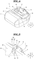
- FIG. 4 is a perspective view for illustrating the printer 1 from which the belt clip 50 and the battery 40 are removed.
- the battery accommodation portion 35 includes an accommodation bottom portion 52 and an accommodation opening portion 57.
- the accommodation opening portion 57 is formed into a rectangular recessed shape by first to fourth side walls 53 to 56 to be opened in the back wall 33.
- the accommodation bottom portion 52 is formed into a rectangular shape.
- the first to fourth side walls 53 to 56 extend upright from four sides of the accommodation bottom portion 52 toward the back wall 33, and thus form a rectangular frame shape.
- the first side wall (side wall) 53 and the second side wall 54 are formed with an interval in the X direction.
- the first side wall 53 is formed at an end portion of the back wall 33 of the casing 3 on the one side in the X direction.
- the second side wall 54 is formed at a center region of the back wall 33 of the casing 3 in the X direction.
- the third side wall 55 and the fourth side wall 56 are formed with an interval in the Y direction.
- the battery 40 is freely removably accommodated in the battery accommodation portion 35 through the accommodation opening portion 57 formed in the back wall 33 of the casing 3.
- FIG. 5 is a perspective view for illustrating a coupling portion 61 of the casing 3.
- FIG. 6 is a front view for illustrating a state in which the coupling portion 61 of the casing 3 is seen from the battery accommodation portion 35 side.
- the coupling portion 61 is formed in the back wall 33 of the casing 3.
- the coupling portion 61 is formed so as to communicate with the battery accommodation portion 35.
- the coupling portion 61 includes a first opening portion 62, a second opening portion (opening portion) 63, and a spherical receiving portion 64.
- the coupling portion 61 is formed into a recessed portion by the first opening portion 62, the second opening portion 63, and the spherical receiving portion 64.
- the first opening portion 62 is formed at a vicinity of the first side wall 53 and at a center in the Y direction in the back wall 33 of the casing 3, and has an arc shape with a diameter D1.
- the first opening portion 62 is formed so as to communicate with the spherical receiving portion 64 in the Z direction.
- the second opening portion 63 is formed at a center in the Y direction in the first side wall 53 of the battery accommodation portion 35.
- the second opening portion 63 includes a circular opening portion 66 and a connecting opening portion 67.
- the circular opening portion 66 is formed into a circular shape with a diameter D2, and is formed so as to allow the battery accommodation portion 35 to communicate with the spherical receiving portion 64 in the X direction.
- the connecting opening portion 67 is formed so as to allow the battery accommodation portion 35 to communicate with the first opening portion 62 in the X direction.
- An opening width W1 of the connecting opening portion 67 in the Y direction is set to be smaller than the diameter D1 of the first opening portion 62 and the diameter D2 of the circular opening portion 66.
- the spherical receiving portion 64 is formed so as to communicate with the circular opening portion 66 and the first opening portion 62.
- the spherical receiving portion 64 is formed into a spherical shape having a dimension of a diameter D3.
- the diameter D3 of the spherical receiving portion 64 is set to be equal to the diameter D2 of the circular opening portion 66 and larger than the diameter D1 of the first opening portion 62.
- a pair of chamfered portions 71 and 72 is formed to be flat.
- the pair of chamfered portions 71 and 72 is referred to as the first chamfered portion 71 and the second chamfered portion 72.
- a chamfer width W2 between the first chamfered portion 71 and the second chamfered portion 72 is set to be smaller than the diameter D3 of the spherical receiving portion 64 and the diameter D2 of the circular opening portion 66.
- a guide groove portion 74 is formed at a center in the Y direction of a region containing the spherical receiving portion 64, the first opening portion 62, and the circular opening portion 66. Specifically, the guide groove portion 74 extends from the first opening portion 62 via the spherical receiving portion 64 to a midway of the circular opening portion 66.
- a ball joint portion 77 (see FIG. 7 ) of the belt clip 50 is coupled to the coupling portion 61 formed as described above. When the ball joint portion 77 is coupled to the coupling portion 61, the belt clip 50 is mounted to the back wall 33 of the casing 3 (see FIG. 3 ).
- FIG. 7 is a front view for illustrating a state in which the belt clip 50 is fitted to the coupling portion 61 of the casing 3.
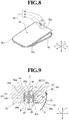
- FIG. 8 is a perspective view for illustrating the belt clip 50.
- the belt clip 50 is integrally formed of a resin material, and includes a clip main body 76 and the ball joint portion (joint portion) 77.
- the clip main body 76 includes a first clip portion 78 and a second clip portion 79.
- the first clip portion 78 is formed into a rectangular shape, and the second clip portion 79 is formed integrally with a proximal portion 78a of the first clip portion 78.
- a belt on a user for the printer 1 may be fitted into a space between the first clip portion 78 and the second clip portion 79.
- the belt clip 50 may be mounted to the belt on the user.
- the ball joint portion 77 is formed integrally with the proximal portion 78a of the first clip portion 78.
- the ball joint portion 77 is protruded from the proximal portion 78a of the first clip portion 78 to a side opposite to the second clip portion 79.
- the ball joint portion 77 includes a joint neck portion 81, a joint spherical body 82, and a joint shank portion 83.
- the joint neck portion 81, the joint spherical body 82, and the joint shank portion 83 are integrally formed of a resin material to be coaxial with each other.
- FIG. 9 is a sectional view for illustrating the printer 1 taken along the line IV-IV of FIG. 7 .
- the joint neck portion 81 is formed into a columnar shape having a diameter D4, and is fitted to the first opening portion 62 of the coupling portion 61 so as to be freely pivotable.
- the joint spherical body 82 is formed into a spherical shape having a diameter D5, and is fitted to the spherical receiving portion 64 (see FIG. 5 ) of the coupling portion 61 so as to be freely pivotable. Under this state, a contact state of the joint spherical body 82 with, for example, the spherical receiving portion 64 of the coupling portion 61 is kept.
- the joint spherical body 82 has a spherical surface, and includes a pair of spherical chamfered portions 84 and 85 and a plurality of groove portions 86 to 89.
- the plurality of groove portions 86 to 89 are referred to as first to fourth groove portions 86 to 89.
- the pair of spherical chamfered portions 84 and 85 are referred to as a first spherical chamfered portion 84 and a second spherical chamfered portion 85, respectively.
- the first spherical chamfered portion 84 and the second spherical chamfered portion 85 are formed to be flat on both side portions of the joint spherical body 82, which are opposed to each other in the Y direction under a state in which the belt clip 50 is mounted at a mounting position in the back wall 33 of the casing 3.
- the mounting position refers to a position at which the belt clip 50 is arranged along the X direction so as to cover the battery 40 as illustrated in FIG. 3 .
- a spherical chamfer width W3 between the first spherical chamfered portion 84 and the second spherical chamfered portion 85 is set to be smaller than the diameter D5 of the joint spherical body 82.
- the first spherical chamfered portion 84 and the second spherical chamfered portion 85 are arranged at positions of being opposed to a first chamfered portion 71 and a second chamfered portion 72 of the coupling portion 61, respectively.
- a contact state of the first spherical chamfered portion 84 with, for example, the first chamfered portion 71 and a contact state of the second spherical chamfered portion 85 with, for example, the second chamfered portion 72 are kept.
- a first engagement portion (engagement portion) 92 is formed under a state in which the first spherical chamfered portion 84 is opposed to the first chamfered portion 71. Further, under a state in which the second spherical chamfered portion 85 is opposed to the second chamfered portion 72, a second engagement portion (engagement portion) 93 is formed.
- the first engagement portion 92 and the second engagement portion 93 are formed along a pivoting direction of the belt clip 50 in at least two locations at a given interval.
- the first to fourth groove portions 86 to 89 are formed in a region between the first spherical chamfered portion 84 and the second spherical chamfered portion 85 in the spherical surface of the joint spherical body 82 at positions avoiding the first spherical chamfered portion 84 and the second spherical chamfered portion 85.
- the first groove portion 86 is formed on one end 84a side of the first spherical chamfered portion 84.
- the second groove portion 87 is formed on another end 84b side of the first spherical chamfered portion 84.
- the third groove portion 88 is formed on one end 85a side of the second spherical chamfered portion 85.
- the fourth groove portion 89 is formed on another end 85b side of the second spherical chamfered portion 85.
- the joint spherical body 82 may be elastically deformed further suitably. Further, owing to formation of the first to fourth groove portions 86 to 89 in the joint spherical body 82, when the belt clip 50 is molded from a resin material, formation of shrink marks on the joint spherical body 82 may be prevented. Accordingly, the joint spherical body 82 may be molded with high accuracy.
- first groove portion 86 and the fourth groove portion 89 are formed so as to be opposed to each other across a pivot center O1 of the ball joint portion 77.
- a groove width dimension between the first groove portion 86 and the fourth groove portion 89 is represented by W4.
- the third groove portion 88 and the second groove portion 87 are formed so as to be opposed to each other across the pivot center O1 of the ball joint portion 77.
- a groove width dimension between the third groove portion 88 and the second groove portion 87 is represented by W4.
- the groove width dimension W4 is set to be smaller than the diameter D5 of the joint spherical body 82.
- FIG. 10 is a sectional view for illustrating a state in which the battery 40 is covered with the belt clip 50.
- the joint shank portion 83 is formed into a columnar shape having a diameter D6 smaller than that of the joint neck portion 81, and is fitted to a groove portion 74a of the guide groove portion 74 of the coupling portion 61, which is formed in the spherical receiving portion 64, so as to be freely pivotable. Under this state, a contact state of the joint shank portion 83 with, for example, an end portion 74b of the guide groove portion 74 is kept.
- the belt clip 50 may be prevented from moving with the joint spherical body 82 as a center in a direction of separating away from the back wall 33 of the casing 3. With this, the belt clip 50 is held in a stable state along the back wall 33 of the casing 3 (in a state of being mounted at a use position in FIG. 3 and FIG. 10 ).
- the battery 40 Under a state in which the ball joint portion 77 is coupled to the coupling portion 61, the battery 40 is accommodated in the battery accommodation portion 35. The second opening portion 63 of the coupling portion 61 is closed by the accommodated battery 40. Accordingly, the ball joint portion 77 is held under a state of being fitted to the coupling portion 61. That is, the battery 40 may be also used as a member configured to hold the ball joint portion 77 in the coupling portion 61. Thus, the number of components may be reduced, and simplification of the configuration may be achieved.
- FIG. 11 is a back view for illustrating a state in which the belt clip 50 of the printer 1 is arranged at the mounting position.
- the first engagement portion 92 is formed under a state in which the first spherical chamfered portion 84 is opposed to the first chamfered portion 71.
- the second engagement portion 93 is formed under a state in which the second spherical chamfered portion 85 is opposed to the second chamfered portion 72.
- the first engagement portion 92 and the second engagement portion 93 may restrain the belt clip 50 from shifting from the mounting position. Accordingly, with a simple configuration having the ball joint portion 77 of the belt clip 50 and the coupling portion 61, the belt clip 50 may be fitted to the coupling portion 61 so as to be pivotable, and may be restrained from shifting from the mounting position. Thus, the number of parts of the printer 1 may be reduced.
- the belt clip 50 (or the ball joint portion 77) may be stably held at the mounting position. Accordingly, for example, when the printer 1 is mounted to the belt through intermediation of the belt clip 50, the belt clip 50 may be stabilized. With this structure, such a trouble as mounting the printer 1 to the belt on the user is facilitated, thereby being capable of enhancing operability of the printer 1. Moreover, under a state in which the first engagement portion 92 and the second engagement portion 93 restrain the belt clip 50 from shifting from the mounting position, the battery 40 is covered with the belt clip 50. With this structure, the belt clip 50 may prevent the battery 40 from falling off the battery accommodation portion 35 of the casing 3.
- the belt clip 50 is pivoted about the ball joint portion 77 along the back wall 33 of the casing 3 in a counterclockwise direction as indicated by the arrow A.
- the first to fourth groove portions 86 to 89 are formed in the joint spherical body 82.
- the belt clip 50 (that is, the joint spherical body 82) is formed of a resin material so as to be elastically deformable. Specifically, when the belt clip 50 is pivoted about the ball joint portion 77 in the direction indicated by the arrow A, a relatively large load is applied.
- spherical portions 82a and 82b of the joint spherical body 82 which are on a side having the first groove portion 86 and the third groove portion 88, may be elastically deformed along the first chamfered portion 71.
- spherical portions 82c and 82d of the joint spherical body 82 which are on a side having the fourth groove portion 89 and the second groove portion 87, may be elastically deformed along the second chamfered portion 72.
- the belt clip 50 may be pivoted about the ball joint portion 77 along the back wall 33 of the casing 3 in the direction indicated by the arrow A.
- the groove width dimension W4 between the first groove portion 86 and the fourth groove portion 89 is set to be smaller than the diameter D5 of the joint spherical body 82. Further, the groove width dimension W4 between the third groove portion 88 and the second groove portion 87 is set to be smaller than the diameter D5 of the joint spherical body 82.
- the first groove portion 86 and the third groove portion 88 reach the first chamfered portion 71.
- the fourth groove portion 89 and the second groove portion 87 reach the second chamfered portion 72. At this time, the load acting on the belt clip 50 may be reduced.
- first groove portion 86 and the fourth groove portion 89 are formed so as to be opposed to each other across the pivot center O1 of the ball joint portion 77.
- the second groove portion 87 and the third groove portion 88 are formed so as to be opposed to each other across the pivot center O1 of the ball joint portion 77. Accordingly, for example, when the belt clip 50 is turned in a clockwise direction opposite to the counterclockwise direction, similarly to the first groove portion 86 and the fourth groove portion 89, which are opposed to each other, the second groove portion 87 and the fourth groove portion 88, which are opposed to each other may be elastically deformed. With this structure, when the belt clip 50 is pivoted in the clockwise direction, the same click feeling as that in the case of turning the belt clip 50 in the counterclockwise direction may be obtained.
- FIG. 12 is a back view for illustrating a state in which the belt clip 50 of the printer 1 is arranged at a removable position.
- the removable position refers to a position at which the belt clip 50 is arranged away from the battery 40 along the X direction.
- a contact state of the first spherical chamfered portion 84 with the second chamfered portion 72 is kept.
- a contact state of the second spherical chamfered portion 85 with the first chamfered portion 71 is kept.
- the belt clip 50 is arranged at the removable position so that the belt clip 50 is arranged at a position of avoiding the battery 40. Accordingly, the battery 40 may be removed from the battery accommodation portion 35.
- the battery 40 is removed from the battery accommodation portion 35, fitting of the ball joint portion 77 of the belt clip 50 to the coupling portion 61 may easily be performed, or the fitting of the ball joint portion 77 of the belt clip 50 to the coupling portion 61 may easily be canceled.
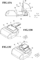
- FIG. 13A is a sectional view for illustrating an example in which the ball joint portion 77 of the belt clip 50 is fitted to the coupling portion 61 of the casing 3.
- FIG. 13B is a perspective view for illustrating an example in which the battery 40 is accommodated in the battery accommodation portion 35 of the casing 3.
- FIG. 13C is a perspective view for illustrating an example in which the battery 40 is covered with the belt clip 50.
- the belt clip 50 is arranged so as to intersect the back wall 33 of the casing 3.
- the ball joint portion 77 of the belt clip 50 is fitted to the coupling portion 61 through the second opening portion 63 of the coupling portion 61 in a direction indicated by the arrow B.
- the belt clip 50 may be rocked in a direction indicated by the arrow C.
- the belt clip 50 is arranged at the position avoiding the battery accommodation portion 35. Under this state, the battery 40 is accommodated in the battery accommodation portion 35 in a direction indicated by the arrow D.
- the second opening portion 63 (see FIG. 13A ) of the coupling portion 61 is closed by the accommodated battery 40. Accordingly, the ball joint portion 77 is held in a state of being fitted to the coupling portion 61.
- the belt clip 50 is turned about the ball joint portion 77 ( FIG. 13A ) in a direction indicated by the arrow E.
- the battery 40 is covered with the belt clip 50.
- the belt clip 50 may prevent the battery 40 from falling off the battery accommodation portion 35 of the casing 3.
- printer 100 Next, description is made of a printer 100 according to a second embodiment of the present invention with reference to FIG. 14 to FIG. 16 .
- components that are the same as or similar to those of the printer 1 according to the first embodiment are denoted by the same reference symbols, and detailed description thereof is omitted.
- FIG. 14 is a perspective view for illustrating the printer 100 as seen from a back wall side thereof.
- an attachment member 102 for a strap is used in place of the belt clip 50 of the printer 1 according to the first embodiment, and the remaining configuration is the same as that of the printer 1 according to the first embodiment.
- the attachment member 102 is mounted to the back wall 33 of the casing 3.
- the attachment member 102 is freely removably mounted to an end portion 33a of the back wall 33 of the casing 3 in the X direction so as to avoid the battery accommodation portion 35 and the battery 40.
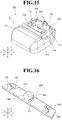
- FIG. 15 is a perspective view for illustrating the printer 100 from which the attachment member 102 and the battery 40 are removed.
- the casing 3 includes a coupling recessed portion 104 and a pair of insertion recessed portions 105 and 106 formed in the back wall 33 of the casing 3 at vicinities of the battery accommodation portion 35.
- the coupling recessed portion 104 is formed at an end portion of the casing 3 in the X direction and at a center thereof in the Y direction.
- the coupling recessed portion 104 includes a coupling opening portion 112, a first chamfered portion 113, and a second chamfered portion 114.
- the first chamfered portion 113 and the second chamfered portion 114 are formed to be flat.
- the coupling opening portion 112 is opened in the first side wall 53 of the battery accommodation portion 35.
- the first chamfered portion 113 and the second chamfered portion 114 are formed on portions opposed to each other in the Y direction.
- the pair of insertion recessed portions 105 and 106 are formed on both sides of the coupling recessed portion 104 in the Y direction, respectively.
- the pair of insertion recessed portions 105 and 106 include insertion opening portions 116 and 117, respectively, which are opened in the first side wall 53 of the battery accommodation portion 35.
- the attachment member 102 (see FIG. 16 ) is freely removably mounted to the coupling recessed portion 104 and the pair of insertion recessed portions 105 and 106.
- FIG. 16 is a perspective view for illustrating the attachment member 102.
- the attachment member 102 includes a support bracket 121, a coupling projecting portion (joint portion) 122, and a pair of ribs 124 and 125.
- the support bracket 121 is formed into a flat plate-like shape, and has a pair of hook holes 128 in both end portions thereof in the Y direction.
- the pair of hook holes 128 is formed to enable a strap to be coupled to the attachment member 102 through insertion of the strap.
- the coupling projecting portion 122 is formed at a center of the support bracket 121 in the Y direction.
- the coupling projecting portion 122 is formed so as to extend toward the X direction in a columnar shape.
- the coupling projecting portion 122 includes a first coupling chamfered portion 131 and a second coupling chamfered portion 132 at both ends thereof in the Y direction.
- the first coupling chamfered portion 131 and the second coupling chamfered portion 132 are formed to be flat.
- the coupling projecting portion 122 is freely removably coupled to the coupling recessed portion 104 through the coupling opening portion 112. Under a state in which the coupling projecting portion 122 is coupled to the coupling recessed portion 104, the first coupling chamfered portion 131 and the first chamfered portion 113 are arranged so as to be held in contact with each other in an opposed state. Under this state, the first coupling chamfered portion 131 and the first chamfered portion 113 form a first pivot restraining portion. Further, the second coupling chamfered portion 132 and the second chamfered portion 114 are arranged so as to be held in contact with each other in an opposed state.
- the second coupling chamfered portion 132 and the second chamfered portion 114 form a second pivot restraining portion.
- the coupling projecting portion 122 is formed into a columnar shape, and the first pivot restraining portion and the second pivot restraining portion are formed.
- the attachment member 102 is restrained from pivoting.
- the pair of ribs 124 and 125 are freely removably coupled to the insertion recessed portions 105 and 106, respectively, through the pair of insertion opening portions 116 and 117.
- pivoting of the attachment member 102 is further satisfactorily restrained.
- the battery 40 Under a state in which the attachment member 102 is mounted to the back wall 33 of the casing 3, the battery 40 is accommodated in the battery accommodation portion 35. Accordingly, the coupling opening portion 112 of the coupling recessed portion and the insertion opening portions of the insertion recessed portions are closed by the battery 40. With this, the attachment member 102 may be prevented from being removed from the back wall 33 of the casing 3. Meanwhile, when the attachment member is removed from the back wall 33 of the casing 3, the battery 40 is removed from the battery accommodation portion 35 so that the coupling projecting portion 122 may be removed from the coupling opening portion 112 of the coupling recessed portion 104.
- the pair of ribs 124 and 125 may be removed from the pair of insertion opening portions 116 and 117, respectively, of the insertion recessed portions 105 and 106.
- the attachment member 102 may easily be mounted to and removed from the back wall 33 of the casing 3.
- the attachment member 102 is removably mounted to the casing 3, and the pair of hook holes 128 is formed in the attachment member 102.
- a strap may be mounted to the pair of hook holes 128. Accordingly, the strap may be removably mounted to the attachment member 102.
- the attachment member 102 is mounted to the casing 3 so that the strap may be mounted to the printer 100 through intermediation of the attachment member 102.
- the printer 100 may be used in a carried state of being suspended from a shoulder or a neck.
- the attachment member 102 is removed from the casing 3 so that the attachment member 102 and the strap may be removed from the printer 100.
- the printer 100 when the printer 100 is used under a state of being put at the predetermined position, it is not required to consider an installation space for installing the attachment member 102 and the strap, and thus an installation position for the printer 100 may easily be secured. Further, when the printer 100 is used under a state of being put at the predetermined position without being carried, the attachment member 102 and the strap may be omitted. Thus, cost of the printer 100 may be reduced.
- the printer 100 when the printer 100 is in the carried state of being suspended from a shoulder or a neck through use of the strap, the printer 100 may be kept in a stable state when the recording sheet P1 is cut through use of the first cutting blade 26 or the second cutting blade 27 (that is, a manual cutter) illustrated in FIG. 2 .
- the recording sheet P1 may be unforcedly and satisfactorily cut by the first cutting blade 26 or the second cutting blade 27, and hence operability of the printer 100 may be enhanced.
- the technical scope of the present invention is not limited to the above-mentioned embodiments, but various modifications may be made without departing from the gist of the present invention.
- the mounting position of the belt clip 50 is the position at which the belt clip 50 is arranged along the X direction so as to cover the battery 40, but the present invention is not limited thereto.
- the mounting position of the belt clip 50 may be a position at which the belt clip 50 is arranged obliquely to the X direction so as to cover at least a part of the battery 40.
- first engagement portion 92 and the second engagement portion 93 are provided as the engagement portion, but the present invention is not limited thereto. As another example, for example, three or more engagement portions may be provided.
- the belt clip 50 to be mounted to a belt on a user is exemplified as a clip, but the present invention is not limited thereto.
- a clip may be mounted to a different portion.
Landscapes
- Engineering & Computer Science (AREA)
- General Engineering & Computer Science (AREA)
- Mechanical Engineering (AREA)
- Printers Characterized By Their Purpose (AREA)
- Accessory Devices And Overall Control Thereof (AREA)
Abstract
Description
- The present invention relates to a printer.
- Hitherto, there have been widely used portable devices such as a mobile printer, which may be readily carried by a person. In general, such portable device includes a battery that is to be removably mounted to a housing so as to enable the portable device to be used under a cordless state. Further, in many cases, the portable device includes a belt clip (hereinafter, referred to as "clip") in order to enable a user to use the portable device while wearing the portable device on a belt or the like.
- In the portable device of this type, in order to prevent falling off of the battery mounted to a rear surface of the housing, the clip is provided on the rear surface of the housing so as to cover a part of the battery. However, in a case of employing such a structure that the clip covers the battery, the clip obstructs mounting and removal of the battery, and hence such a trouble as temporarily removing the clip is required. Meanwhile, in order to remove the battery, when employing such a configuration that the clip is pivotable about a support portion formed in the rear surface of the housing, the number of parts is increased, resulting in uneconomical effects.
- In view of this, in the portable device of this type, it has been required that prevention of falling off of the battery and reduction in number of parts may be achieved.
- According to one embodiment of the present invention, there is provided a printer, including: a housing configured to accommodate a recording sheet and a printing portion; a battery to be removably mounted to the housing; and a clip pivotably mounted to the housing, wherein the clip includes a joint portion, which is elastically deformable so that a coupling portion of the housing is pivotably fitted to the joint portion, wherein each of the joint portion and the coupling portion includes an engagement portion configured to restrain the clip from pivoting at a mounting position at which the clip covers at least a part of the battery, and wherein, when a predetermined external force is applied to the housing in a pivoting direction of the clip, restraining of the clip by the engagement portions is canceled so that the clip is movable from the mounting position.
- In the above-mentioned printer according to one embodiment of the present invention, the printer further includes: a battery accommodation portion, which is formed in the housing such that the battery is to be removably mounted therein, wherein the coupling portion is a recessed portion having an opening portion, which is formed in a side wall of the battery accommodation portion such that the joint portion is to be removably fitted therethrough.
- In the above-mentioned printer according to one embodiment of the present invention, the engagement portion of the joint portion and the coupling portion comprise at least two engagement portions formed along the pivoting direction of the clip at a given interval.
- In the above-mentioned printer according to one embodiment of the present invention, the joint portion comprises a plurality of groove portions formed along the pivoting direction of the clip so that deformation of the joint portion is allowed when the clip is pivoted.
- In the above-mentioned printer according to one embodiment of the present invention, the plurality of groove portions of the joint portion are formed so as to be opposed to one another across a pivot center of the joint portion.
- Embodiments of the present invention will now be described by way of further example only and with reference to the accompanying drawings, in which:
-
FIG. 1 is a perspective view for illustrating a printer according to a first embodiment of the present invention when a paper cover is positioned at a closed position. -
FIG. 2 is a perspective view for illustrating the printer according to the first embodiment of the present invention when the paper cover is positioned at an open position. -
FIG. 3 is a perspective view for illustrating the printer according to the first embodiment of the present invention as seen from a back wall side thereof. -
FIG. 4 is a perspective view for illustrating the printer according to the first embodiment of the present invention from which a belt clip and a battery are removed. -
FIG. 5 is a perspective view for illustrating a coupling portion of a casing in the first embodiment of the present invention. -
FIG. 6 is a front view for illustrating a state in which the coupling portion of the casing in the first embodiment of the present invention is seen from a battery accommodation portion side. -
FIG. 7 is a front view for illustrating a state in which a belt clip is fitted to the coupling portion of the casing in the first embodiment of the present invention. -
FIG. 8 is a perspective view for illustrating the belt clip in the first embodiment of the present invention. -
FIG. 9 is a sectional view for illustrating the printer according to the first embodiment of the present invention taken along the line IV-IV ofFIG. 7 . -
FIG. 10 is a sectional view for illustrating a state in which the battery in the first embodiment of the present invention is covered with the belt clip. -
FIG. 11 is a back view for illustrating a state in which the belt clip of the printer according to the first embodiment of the present invention is arranged at a mounting position. -
FIG. 12 a back view for illustrating a state in which the belt clip of the printer according to the first embodiment of the present invention is arranged at a removable position. -
FIG. 13A is a sectional view for illustrating an example in which a ball joint portion of the belt clip is fitted to the coupling portion of the casing in the first embodiment of the present invention. -
FIG. 13B is a perspective view for illustrating an example in which the battery is accommodated in the battery accommodation portion of the casing. -
FIG. 13C is a perspective view for illustrating an example in which the battery is covered with the belt clip. -
FIG. 14 is a perspective view for illustrating a printer according to a second embodiment of the present invention as seen from a back wall side thereof. -
FIG. 15 is a perspective view for illustrating the printer according to the second embodiment of the present invention from which an attachment member and the battery are removed. -
FIG. 16 a perspective view for illustrating the attachment member in the second embodiment of the present invention. -
FIG. 1 is a perspective view for illustrating aprinter 1 as seen from a front surface side thereof when apaper cover 20 is positioned at a closed position.FIG. 2 is a perspective view for illustrating theprinter 1 as seen from the front surface side when thepaper cover 20 is positioned at an open position. InFIG. 1 andFIG. 2 , illustration is made of theprinter 1 to be used under a state of being placed on an installation surface. In the following description, in the drawings, a direction indicated by the arrows X, a direction indicated by the arrows Y, and a direction indicated by the arrows Z are defined as a length direction, a width direction, and an up-and-down direction, respectively. - As illustrated in
FIG. 1 , theprinter 1 is configured to be capable of performing printing on a recording sheet P1. In a first embodiment of the present invention, a thermal printer is given as an example of theprinter 1, but theprinter 1 is not limited to the thermal printer. The recording sheet P1 is a heat-sensitive sheet that develops color through application of heat, and is suitably used for printing, for example, a variety of labels, receipts, and tickets. As illustrated inFIG. 2 , the recording sheet P1 is set in theprinter 1 under a state of a roll sheet PR having ahollow hole 5, which is obtained by winding the recording sheet P1. Aprinting portion 6 is configured to perform printing on a part drawn out from the roll sheet PR. - The
printer 1 includes a casing (housing) 3 having anopening portion 3a, thepaper cover 20 configured to open and close theopening portion 3a of thecasing 3, abattery 40 for charging, and a belt clip (clip) 50 (seeFIG. 3 ) for carrying. Further, aprinter module 30 is mounted inside theprinter 1. - The
casing 3 is made of plastic such as polycarbonate or a metal material. Thecasing 3 is formed into such a box shape that a region on one side in the X direction is formed into a substantially rectangular parallelepiped shape having afront wall 10, and that a region on another side in the X direction is opened to one side in the Z direction (to thefront wall 10 side). For example, a rib (not shown) is formed on an inner surface of thecasing 3, thereby reinforcing mechanical strength of thecasing 3. Anoperation unit 14 is arranged on thefront wall 10 of thecasing 3, and is configured to perform various operations of theprinter 1. - Various function switches 15 such as a power switch and a FEED switch are arranged in the
operation unit 14. Moreover,various indicators 16 are arranged in theoperation unit 14 to be adjacent to thevarious function switches 15. Examples of theindicators 16 include a POWER indicator configured to indicate information of an ON/OFF state of the power switch, and an ERROR indicator configured to indicate, for example, an error of theprinter 1. Further, anopen button 18 for thepaper cover 20 is provided between thefront wall 10 and aside wall 12 of thecasing 3. Moreover, afirst cutting blade 26 configured to cut the recording sheet P1 is formed at an edge of thefront wall 10 of thecasing 3 on the another side in the X direction. - The
paper cover 20 is made of plastic such as polycarbonate. A proximal end portion of thepaper cover 20 on the another side in the X direction is supported by a hinge shaft so that thepaper cover 20 is rotatable with respect to amain body frame 31 of theprinter module 30. Further, a distal end portion of thepaper cover 20 is configured to be capable of being locked to themain body frame 31 by aplaten roller 51 mounted to the distal end portion of thepaper cover 20. Through pressing of theopen button 18 of thecasing 3, locking between thepaper cover 20 and thecasing 3, in which themain body frame 31 is mounted, is cancelled so that thepaper cover 20 may be opened from the closed position (seeFIG. 1 ) to the open position (seeFIG. 2 ). - Further, as illustrated in
FIG. 1 , when thepaper cover 20 is positioned at the closed position, a gap is defined along the width direction of the recording sheet P1 between a distal edge of thepaper cover 20 and the edge of thefront wall 10 of thecasing 3 on the another side in the X direction. The gap forms adelivery slot 19 through which the recording sheet P1 subjected to printing is delivered. Moreover, a second cutting blade 27 (seeFIG. 2 ) configured to cut the recording sheet P1 is formed at the distal end portion of thepaper cover 20. Printing is performed on the recording sheet P1 in theprinting portion 6, and the recording sheet P1 subjected to printing is delivered through thedelivery slot 19. The recording sheet P1 delivered through thedelivery slot 19 is cut by being pulled down in a contact state with thefirst cutting blade 26 or thesecond cutting blade 27. -
FIG. 3 is a perspective view for illustrating theprinter 1 as seen from aback wall 33 side. As illustrated inFIG. 3 , thebattery 40 and thebelt clip 50 are mounted to theback wall 33 of thecasing 3. Abattery accommodation portion 35 is formed on theback wall 33 of thecasing 3. Thebattery 40 is removably mounted to thebattery accommodation portion 35. Thebattery 40 is formed into a rectangular shape. When thebattery 40 is accommodated in thebattery accommodation portion 35, thebattery 40 may be used as a power source for theprinter 1. Thus, theprinter 1 may be used as a portable terminal in a cordless state. -
FIG. 4 is a perspective view for illustrating theprinter 1 from which thebelt clip 50 and thebattery 40 are removed. As illustrated inFIG. 4 , thebattery accommodation portion 35 includes anaccommodation bottom portion 52 and anaccommodation opening portion 57. Theaccommodation opening portion 57 is formed into a rectangular recessed shape by first tofourth side walls 53 to 56 to be opened in theback wall 33. Theaccommodation bottom portion 52 is formed into a rectangular shape. The first tofourth side walls 53 to 56 extend upright from four sides of theaccommodation bottom portion 52 toward theback wall 33, and thus form a rectangular frame shape. The first side wall (side wall) 53 and thesecond side wall 54 are formed with an interval in the X direction. Thefirst side wall 53 is formed at an end portion of theback wall 33 of thecasing 3 on the one side in the X direction. Thesecond side wall 54 is formed at a center region of theback wall 33 of thecasing 3 in the X direction. Thethird side wall 55 and thefourth side wall 56 are formed with an interval in the Y direction. Thebattery 40 is freely removably accommodated in thebattery accommodation portion 35 through theaccommodation opening portion 57 formed in theback wall 33 of thecasing 3. -
FIG. 5 is a perspective view for illustrating acoupling portion 61 of thecasing 3.FIG. 6 is a front view for illustrating a state in which thecoupling portion 61 of thecasing 3 is seen from thebattery accommodation portion 35 side. As illustrated inFIG. 5 andFIG. 6 , thecoupling portion 61 is formed in theback wall 33 of thecasing 3. Thecoupling portion 61 is formed so as to communicate with thebattery accommodation portion 35. Thecoupling portion 61 includes afirst opening portion 62, a second opening portion (opening portion) 63, and aspherical receiving portion 64. Thecoupling portion 61 is formed into a recessed portion by thefirst opening portion 62, thesecond opening portion 63, and thespherical receiving portion 64. Thefirst opening portion 62 is formed at a vicinity of thefirst side wall 53 and at a center in the Y direction in theback wall 33 of thecasing 3, and has an arc shape with a diameter D1. Thefirst opening portion 62 is formed so as to communicate with thespherical receiving portion 64 in the Z direction. Thesecond opening portion 63 is formed at a center in the Y direction in thefirst side wall 53 of thebattery accommodation portion 35. - The
second opening portion 63 includes acircular opening portion 66 and a connectingopening portion 67. Thecircular opening portion 66 is formed into a circular shape with a diameter D2, and is formed so as to allow thebattery accommodation portion 35 to communicate with thespherical receiving portion 64 in the X direction. The connectingopening portion 67 is formed so as to allow thebattery accommodation portion 35 to communicate with thefirst opening portion 62 in the X direction. An opening width W1 of the connectingopening portion 67 in the Y direction is set to be smaller than the diameter D1 of thefirst opening portion 62 and the diameter D2 of thecircular opening portion 66. - The
spherical receiving portion 64 is formed so as to communicate with thecircular opening portion 66 and thefirst opening portion 62. Thespherical receiving portion 64 is formed into a spherical shape having a dimension of a diameter D3. The diameter D3 of thespherical receiving portion 64 is set to be equal to the diameter D2 of thecircular opening portion 66 and larger than the diameter D1 of thefirst opening portion 62. On both side regions of thespherical receiving portion 64 and thecircular opening portion 66, which are opposed to each other in the Y direction, a pair ofchamfered portions chamfered portions portion 71 and the second chamferedportion 72. A chamfer width W2 between the first chamferedportion 71 and the second chamferedportion 72 is set to be smaller than the diameter D3 of thespherical receiving portion 64 and the diameter D2 of thecircular opening portion 66. - A
guide groove portion 74 is formed at a center in the Y direction of a region containing thespherical receiving portion 64, thefirst opening portion 62, and thecircular opening portion 66. Specifically, theguide groove portion 74 extends from thefirst opening portion 62 via thespherical receiving portion 64 to a midway of thecircular opening portion 66. A ball joint portion 77 (seeFIG. 7 ) of thebelt clip 50 is coupled to thecoupling portion 61 formed as described above. When the balljoint portion 77 is coupled to thecoupling portion 61, thebelt clip 50 is mounted to theback wall 33 of the casing 3 (seeFIG. 3 ). -
FIG. 7 is a front view for illustrating a state in which thebelt clip 50 is fitted to thecoupling portion 61 of thecasing 3.FIG. 8 is a perspective view for illustrating thebelt clip 50. As illustrated inFIG. 7 andFIG. 8 , thebelt clip 50 is integrally formed of a resin material, and includes a clipmain body 76 and the ball joint portion (joint portion) 77. The clipmain body 76 includes afirst clip portion 78 and asecond clip portion 79. Thefirst clip portion 78 is formed into a rectangular shape, and thesecond clip portion 79 is formed integrally with aproximal portion 78a of thefirst clip portion 78. By elastically deforming thesecond clip portion 79 to separate adistal end portion 79a of thesecond clip portion 79 away from thefirst clip portion 78, a belt on a user for theprinter 1 may be fitted into a space between thefirst clip portion 78 and thesecond clip portion 79. In this manner, thebelt clip 50 may be mounted to the belt on the user. The balljoint portion 77 is formed integrally with theproximal portion 78a of thefirst clip portion 78. - The ball
joint portion 77 is protruded from theproximal portion 78a of thefirst clip portion 78 to a side opposite to thesecond clip portion 79. The balljoint portion 77 includes ajoint neck portion 81, a jointspherical body 82, and ajoint shank portion 83. Thejoint neck portion 81, the jointspherical body 82, and thejoint shank portion 83 are integrally formed of a resin material to be coaxial with each other. -
FIG. 9 is a sectional view for illustrating theprinter 1 taken along the line IV-IV ofFIG. 7 . As illustrated inFIG. 7 andFIG. 9 , thejoint neck portion 81 is formed into a columnar shape having a diameter D4, and is fitted to thefirst opening portion 62 of thecoupling portion 61 so as to be freely pivotable. The jointspherical body 82 is formed into a spherical shape having a diameter D5, and is fitted to the spherical receiving portion 64 (seeFIG. 5 ) of thecoupling portion 61 so as to be freely pivotable. Under this state, a contact state of the jointspherical body 82 with, for example, thespherical receiving portion 64 of thecoupling portion 61 is kept. The jointspherical body 82 has a spherical surface, and includes a pair of sphericalchamfered portions groove portions 86 to 89. In the following description, the plurality ofgroove portions 86 to 89 are referred to as first tofourth groove portions 86 to 89. Further, the pair of sphericalchamfered portions portion 84 and a second spherical chamferedportion 85, respectively. - The first spherical chamfered
portion 84 and the second spherical chamferedportion 85 are formed to be flat on both side portions of the jointspherical body 82, which are opposed to each other in the Y direction under a state in which thebelt clip 50 is mounted at a mounting position in theback wall 33 of thecasing 3. Herein, the mounting position refers to a position at which thebelt clip 50 is arranged along the X direction so as to cover thebattery 40 as illustrated inFIG. 3 . A spherical chamfer width W3 between the first spherical chamferedportion 84 and the second spherical chamferedportion 85 is set to be smaller than the diameter D5 of the jointspherical body 82. - Under a state in which the
belt clip 50 is mounted at the mounting position in theback wall 33 of thecasing 3, the first spherical chamferedportion 84 and the second spherical chamferedportion 85 are arranged at positions of being opposed to a first chamferedportion 71 and a second chamferedportion 72 of thecoupling portion 61, respectively. Under this state, a contact state of the first spherical chamferedportion 84 with, for example, the first chamferedportion 71 and a contact state of the second spherical chamferedportion 85 with, for example, the second chamferedportion 72 are kept. In this case, for example, under a state in which the first spherical chamferedportion 84 is opposed to the first chamferedportion 71, a first engagement portion (engagement portion) 92 is formed. Further, under a state in which the second spherical chamferedportion 85 is opposed to the second chamferedportion 72, a second engagement portion (engagement portion) 93 is formed. Thefirst engagement portion 92 and thesecond engagement portion 93 are formed along a pivoting direction of thebelt clip 50 in at least two locations at a given interval. - The first to
fourth groove portions 86 to 89 are formed in a region between the first spherical chamferedportion 84 and the second spherical chamferedportion 85 in the spherical surface of the jointspherical body 82 at positions avoiding the first spherical chamferedportion 84 and the second spherical chamferedportion 85. Thefirst groove portion 86 is formed on oneend 84a side of the first spherical chamferedportion 84. Thesecond groove portion 87 is formed on anotherend 84b side of the first spherical chamferedportion 84. Thethird groove portion 88 is formed on oneend 85a side of the second spherical chamferedportion 85. Thefourth groove portion 89 is formed on anotherend 85b side of the second spherical chamferedportion 85. - Owing to formation of the first to
fourth groove portions 86 to 89 in the jointspherical body 82, the jointspherical body 82 may be elastically deformed further suitably. Further, owing to formation of the first tofourth groove portions 86 to 89 in the jointspherical body 82, when thebelt clip 50 is molded from a resin material, formation of shrink marks on the jointspherical body 82 may be prevented. Accordingly, the jointspherical body 82 may be molded with high accuracy. - Further, the
first groove portion 86 and thefourth groove portion 89 are formed so as to be opposed to each other across a pivot center O1 of the balljoint portion 77. A groove width dimension between thefirst groove portion 86 and thefourth groove portion 89 is represented by W4. Thethird groove portion 88 and thesecond groove portion 87 are formed so as to be opposed to each other across the pivot center O1 of the balljoint portion 77. A groove width dimension between thethird groove portion 88 and thesecond groove portion 87 is represented by W4. The groove width dimension W4 is set to be smaller than the diameter D5 of the jointspherical body 82. -
FIG. 10 is a sectional view for illustrating a state in which thebattery 40 is covered with thebelt clip 50. As illustrated inFIG. 10 , thejoint shank portion 83 is formed into a columnar shape having a diameter D6 smaller than that of thejoint neck portion 81, and is fitted to agroove portion 74a of theguide groove portion 74 of thecoupling portion 61, which is formed in thespherical receiving portion 64, so as to be freely pivotable. Under this state, a contact state of thejoint shank portion 83 with, for example, anend portion 74b of theguide groove portion 74 is kept. Accordingly, thebelt clip 50 may be prevented from moving with the jointspherical body 82 as a center in a direction of separating away from theback wall 33 of thecasing 3. With this, thebelt clip 50 is held in a stable state along theback wall 33 of the casing 3 (in a state of being mounted at a use position inFIG. 3 andFIG. 10 ). - Under a state in which the ball
joint portion 77 is coupled to thecoupling portion 61, thebattery 40 is accommodated in thebattery accommodation portion 35. Thesecond opening portion 63 of thecoupling portion 61 is closed by the accommodatedbattery 40. Accordingly, the balljoint portion 77 is held under a state of being fitted to thecoupling portion 61. That is, thebattery 40 may be also used as a member configured to hold the balljoint portion 77 in thecoupling portion 61. Thus, the number of components may be reduced, and simplification of the configuration may be achieved. -
FIG. 11 is a back view for illustrating a state in which thebelt clip 50 of theprinter 1 is arranged at the mounting position. As illustrated inFIG. 9 andFIG. 11 , under a state in which thebelt clip 50 is mounted at a use position in theback wall 33 of thecasing 3, thefirst engagement portion 92 is formed under a state in which the first spherical chamferedportion 84 is opposed to the first chamferedportion 71. Further, thesecond engagement portion 93 is formed under a state in which the second spherical chamferedportion 85 is opposed to the second chamferedportion 72. - With this structure, under a state in which the
belt clip 50 is arranged at the mounting position along theback wall 33 of thecasing 3, thefirst engagement portion 92 and thesecond engagement portion 93 may restrain thebelt clip 50 from shifting from the mounting position. Accordingly, with a simple configuration having the balljoint portion 77 of thebelt clip 50 and thecoupling portion 61, thebelt clip 50 may be fitted to thecoupling portion 61 so as to be pivotable, and may be restrained from shifting from the mounting position. Thus, the number of parts of theprinter 1 may be reduced. - Further, the belt clip 50 (or the ball joint portion 77) may be stably held at the mounting position. Accordingly, for example, when the
printer 1 is mounted to the belt through intermediation of thebelt clip 50, thebelt clip 50 may be stabilized. With this structure, such a trouble as mounting theprinter 1 to the belt on the user is facilitated, thereby being capable of enhancing operability of theprinter 1. Moreover, under a state in which thefirst engagement portion 92 and thesecond engagement portion 93 restrain thebelt clip 50 from shifting from the mounting position, thebattery 40 is covered with thebelt clip 50. With this structure, thebelt clip 50 may prevent thebattery 40 from falling off thebattery accommodation portion 35 of thecasing 3. - From this state, the
belt clip 50 is pivoted about the balljoint portion 77 along theback wall 33 of thecasing 3 in a counterclockwise direction as indicated by the arrow A. The first tofourth groove portions 86 to 89 are formed in the jointspherical body 82. Moreover, the belt clip 50 (that is, the joint spherical body 82) is formed of a resin material so as to be elastically deformable. Specifically, when thebelt clip 50 is pivoted about the balljoint portion 77 in the direction indicated by the arrow A, a relatively large load is applied. Thus,spherical portions spherical body 82, which are on a side having thefirst groove portion 86 and thethird groove portion 88, may be elastically deformed along the first chamferedportion 71. Similarly,spherical portions spherical body 82, which are on a side having thefourth groove portion 89 and thesecond groove portion 87, may be elastically deformed along the second chamferedportion 72. Thus, thebelt clip 50 may be pivoted about the balljoint portion 77 along theback wall 33 of thecasing 3 in the direction indicated by the arrow A. - Specifically, when a predetermined external force is applied to the
casing 3 in the direction indicated by the arrow A (pivoting direction) of thebelt clip 50, restraining performed by thefirst engagement portion 92 and thesecond engagement portion 93 is canceled so that thebelt clip 50 may be moved from the mounting position. - In this case, the groove width dimension W4 between the
first groove portion 86 and thefourth groove portion 89 is set to be smaller than the diameter D5 of the jointspherical body 82. Further, the groove width dimension W4 between thethird groove portion 88 and thesecond groove portion 87 is set to be smaller than the diameter D5 of the jointspherical body 82. Thefirst groove portion 86 and thethird groove portion 88 reach the first chamferedportion 71. Similarly, thefourth groove portion 89 and thesecond groove portion 87 reach the second chamferedportion 72. At this time, the load acting on thebelt clip 50 may be reduced. As described above, when thebelt clip 50 is pivoted, magnitudes of loads generated on the first tofourth groove portions 86 to 89 and thespherical portions 82a to 82d may be varied. Thus, when the balljoint portion 77 is pivoted, satisfactory click feeling may be obtained. - Further, the
first groove portion 86 and thefourth groove portion 89 are formed so as to be opposed to each other across the pivot center O1 of the balljoint portion 77. Thesecond groove portion 87 and thethird groove portion 88 are formed so as to be opposed to each other across the pivot center O1 of the balljoint portion 77. Accordingly, for example, when thebelt clip 50 is turned in a clockwise direction opposite to the counterclockwise direction, similarly to thefirst groove portion 86 and thefourth groove portion 89, which are opposed to each other, thesecond groove portion 87 and thefourth groove portion 88, which are opposed to each other may be elastically deformed. With this structure, when thebelt clip 50 is pivoted in the clockwise direction, the same click feeling as that in the case of turning thebelt clip 50 in the counterclockwise direction may be obtained. -
FIG. 12 is a back view for illustrating a state in which thebelt clip 50 of theprinter 1 is arranged at a removable position. As illustrated inFIG. 9 andFIG. 12 , when thebelt clip 50 is pivoted in the direction indicated by the arrow A, thebelt clip 50 is arranged at the removable position. Herein, the removable position refers to a position at which thebelt clip 50 is arranged away from thebattery 40 along the X direction. A contact state of the first spherical chamferedportion 84 with the second chamferedportion 72 is kept. A contact state of the second spherical chamferedportion 85 with the first chamferedportion 71 is kept. With this structure, thebelt clip 50 is stably held at the removable position. - The
belt clip 50 is arranged at the removable position so that thebelt clip 50 is arranged at a position of avoiding thebattery 40. Accordingly, thebattery 40 may be removed from thebattery accommodation portion 35. When thebattery 40 is removed from thebattery accommodation portion 35, fitting of the balljoint portion 77 of thebelt clip 50 to thecoupling portion 61 may easily be performed, or the fitting of the balljoint portion 77 of thebelt clip 50 to thecoupling portion 61 may easily be canceled. - Next, with reference to
FIG. 13A to FIG. 13C , description is made of an example in which the balljoint portion 77 of thebelt clip 50 is fitted to thecoupling portion 61 to mount thebelt clip 50 to thecasing 3.FIG. 13A is a sectional view for illustrating an example in which the balljoint portion 77 of thebelt clip 50 is fitted to thecoupling portion 61 of thecasing 3.FIG. 13B is a perspective view for illustrating an example in which thebattery 40 is accommodated in thebattery accommodation portion 35 of thecasing 3.FIG. 13C is a perspective view for illustrating an example in which thebattery 40 is covered with thebelt clip 50. - As illustrated in
FIG. 13A , under a state in which the battery 40 (seeFIG. 12 ) is removed from thebattery accommodation portion 35, thebelt clip 50 is arranged so as to intersect theback wall 33 of thecasing 3. Under this state, the balljoint portion 77 of thebelt clip 50 is fitted to thecoupling portion 61 through thesecond opening portion 63 of thecoupling portion 61 in a direction indicated by the arrow B. Through use of the balljoint portion 77 fitted to thecoupling portion 61 as a fulcrum, thebelt clip 50 may be rocked in a direction indicated by the arrow C. - As illustrated in
FIG. 13B , thebelt clip 50 is arranged at the position avoiding thebattery accommodation portion 35. Under this state, thebattery 40 is accommodated in thebattery accommodation portion 35 in a direction indicated by the arrow D. The second opening portion 63 (seeFIG. 13A ) of thecoupling portion 61 is closed by the accommodatedbattery 40. Accordingly, the balljoint portion 77 is held in a state of being fitted to thecoupling portion 61. - As illustrated in
FIG. 13C , thebelt clip 50 is turned about the ball joint portion 77 (FIG. 13A ) in a direction indicated by the arrow E. Thebattery 40 is covered with thebelt clip 50. Thus, thebelt clip 50 may prevent thebattery 40 from falling off thebattery accommodation portion 35 of thecasing 3. - Next, description is made of a
printer 100 according to a second embodiment of the present invention with reference toFIG. 14 to FIG. 16 . In theprinter 100 according to the second embodiment, components that are the same as or similar to those of theprinter 1 according to the first embodiment are denoted by the same reference symbols, and detailed description thereof is omitted. -
FIG. 14 is a perspective view for illustrating theprinter 100 as seen from a back wall side thereof. As illustrated inFIG. 14 , in theprinter 100, anattachment member 102 for a strap is used in place of thebelt clip 50 of theprinter 1 according to the first embodiment, and the remaining configuration is the same as that of theprinter 1 according to the first embodiment. In theprinter 100, theattachment member 102 is mounted to theback wall 33 of thecasing 3. Theattachment member 102 is freely removably mounted to anend portion 33a of theback wall 33 of thecasing 3 in the X direction so as to avoid thebattery accommodation portion 35 and thebattery 40. -
FIG. 15 is a perspective view for illustrating theprinter 100 from which theattachment member 102 and thebattery 40 are removed. As illustrated inFIG. 15 , thecasing 3 includes a coupling recessedportion 104 and a pair of insertion recessedportions back wall 33 of thecasing 3 at vicinities of thebattery accommodation portion 35. The coupling recessedportion 104 is formed at an end portion of thecasing 3 in the X direction and at a center thereof in the Y direction. The coupling recessedportion 104 includes acoupling opening portion 112, a first chamferedportion 113, and a second chamferedportion 114. The firstchamfered portion 113 and the second chamferedportion 114 are formed to be flat. - The
coupling opening portion 112 is opened in thefirst side wall 53 of thebattery accommodation portion 35. The firstchamfered portion 113 and the second chamferedportion 114 are formed on portions opposed to each other in the Y direction. The pair of insertion recessedportions portion 104 in the Y direction, respectively. The pair of insertion recessedportions insertion opening portions first side wall 53 of thebattery accommodation portion 35. The attachment member 102 (seeFIG. 16 ) is freely removably mounted to the coupling recessedportion 104 and the pair of insertion recessedportions -
FIG. 16 is a perspective view for illustrating theattachment member 102. As illustrated inFIG. 15 and FIG. 16 , theattachment member 102 includes asupport bracket 121, a coupling projecting portion (joint portion) 122, and a pair ofribs support bracket 121 is formed into a flat plate-like shape, and has a pair of hook holes 128 in both end portions thereof in the Y direction. The pair of hook holes 128 is formed to enable a strap to be coupled to theattachment member 102 through insertion of the strap. Thecoupling projecting portion 122 is formed at a center of thesupport bracket 121 in the Y direction. Thecoupling projecting portion 122 is formed so as to extend toward the X direction in a columnar shape. Thecoupling projecting portion 122 includes a first coupling chamferedportion 131 and a second coupling chamferedportion 132 at both ends thereof in the Y direction. The first coupling chamferedportion 131 and the second coupling chamferedportion 132 are formed to be flat. - The
coupling projecting portion 122 is freely removably coupled to the coupling recessedportion 104 through thecoupling opening portion 112. Under a state in which thecoupling projecting portion 122 is coupled to the coupling recessedportion 104, the first coupling chamferedportion 131 and the first chamferedportion 113 are arranged so as to be held in contact with each other in an opposed state. Under this state, the first coupling chamferedportion 131 and the first chamferedportion 113 form a first pivot restraining portion. Further, the second coupling chamferedportion 132 and the second chamferedportion 114 are arranged so as to be held in contact with each other in an opposed state. Under this state, the second coupling chamferedportion 132 and the second chamferedportion 114 form a second pivot restraining portion. Thecoupling projecting portion 122 is formed into a columnar shape, and the first pivot restraining portion and the second pivot restraining portion are formed. With this, theattachment member 102 is restrained from pivoting. Further, the pair ofribs portions insertion opening portions attachment member 102 is further satisfactorily restrained. - Under a state in which the
attachment member 102 is mounted to theback wall 33 of thecasing 3, thebattery 40 is accommodated in thebattery accommodation portion 35. Accordingly, thecoupling opening portion 112 of the coupling recessed portion and the insertion opening portions of the insertion recessed portions are closed by thebattery 40. With this, theattachment member 102 may be prevented from being removed from theback wall 33 of thecasing 3. Meanwhile, when the attachment member is removed from theback wall 33 of thecasing 3, thebattery 40 is removed from thebattery accommodation portion 35 so that thecoupling projecting portion 122 may be removed from thecoupling opening portion 112 of the coupling recessedportion 104. Further, the pair ofribs insertion opening portions portions attachment member 102 may easily be mounted to and removed from theback wall 33 of thecasing 3. - In the
printer 100 according to the second embodiment, theattachment member 102 is removably mounted to thecasing 3, and the pair of hook holes 128 is formed in theattachment member 102. A strap may be mounted to the pair of hook holes 128. Accordingly, the strap may be removably mounted to theattachment member 102. With this, when theprinter 100 is used in a carried state, theattachment member 102 is mounted to thecasing 3 so that the strap may be mounted to theprinter 100 through intermediation of theattachment member 102. Through use of the strap, theprinter 100 may be used in a carried state of being suspended from a shoulder or a neck. - Meanwhile, when the
printer 100 is used under a state of being put at a predetermined position without being carried, theattachment member 102 is removed from thecasing 3 so that theattachment member 102 and the strap may be removed from theprinter 100. With this structure, when theprinter 100 is used under a state of being put at the predetermined position, it is not required to consider an installation space for installing theattachment member 102 and the strap, and thus an installation position for theprinter 100 may easily be secured. Further, when theprinter 100 is used under a state of being put at the predetermined position without being carried, theattachment member 102 and the strap may be omitted. Thus, cost of theprinter 100 may be reduced. - Further, pivoting of the
attachment member 102 is restrained by the first pivot restraining portion and the second pivot restraining portion. Accordingly, when theprinter 100 is in the carried state of being suspended from a shoulder or a neck through use of the strap, theprinter 100 may be kept in a stable state when the recording sheet P1 is cut through use of thefirst cutting blade 26 or the second cutting blade 27 (that is, a manual cutter) illustrated inFIG. 2 . Thus, the recording sheet P1 may be unforcedly and satisfactorily cut by thefirst cutting blade 26 or thesecond cutting blade 27, and hence operability of theprinter 100 may be enhanced. - Note that, the technical scope of the present invention is not limited to the above-mentioned embodiments, but various modifications may be made without departing from the gist of the present invention. For example, in the first embodiment, description is made of the example in which the mounting position of the
belt clip 50 is the position at which thebelt clip 50 is arranged along the X direction so as to cover thebattery 40, but the present invention is not limited thereto. As another example, for example, the mounting position of thebelt clip 50 may be a position at which thebelt clip 50 is arranged obliquely to the X direction so as to cover at least a part of thebattery 40. - Further, in the first embodiment, description is made of the example in which two engagement portions, namely, the
first engagement portion 92 and thesecond engagement portion 93 are provided as the engagement portion, but the present invention is not limited thereto. As another example, for example, three or more engagement portions may be provided. - Moreover, in the first embodiment, the
belt clip 50 to be mounted to a belt on a user is exemplified as a clip, but the present invention is not limited thereto. As another example, a clip may be mounted to a different portion.
The foregoing description has been given by way of example only and it will be appreciated by a person skilled in the art that modifications can be made without departing from the scope of the present invention as defined by the claims.
Claims (8)
- A printer (1), comprising:a housing (3) configured to accommodate a recording sheet (PI) and a printing portion (6);a battery (40) to be removably mounted to the housing (3); anda clip (50) pivotably mounted to the housing (3),wherein the clip (50) includes a joint portion (77), which is elastically deformable so that a coupling portion (61) of the housing (3) is pivotably fitted to the joint portion (77),wherein each of the joint portion (77) and the coupling portion (61) includes an engagement portion (92, 93) configured to restrain the clip (50) from pivoting at a mounting position at which the clip (50) covers at least a part of the battery (40), andwherein, when a predetermined external force is applied to the housing (3) in a pivoting direction of the clip (50), restraining of the clip (50) by the engagement portions (92, 93) is canceled so that the clip (50) is movable from the mounting position.
- The printer (1) according to claim 1, further comprising a battery accommodation portion (35), which is formed in the housing (3) such that the battery (40) is to be removably mounted therein,
wherein the coupling portion (61) is a recessed portion having an opening portion (62), which is formed in a side wall of the battery accommodation portion (35) such that the joint portion (77) is to be removably fitted therethrough. - The printer (1) according to claim 2, wherein the engagement portion (92, 93) of the joint portion (77) and the coupling portion (61) comprises at least two engagement portions (92, 93) formed along the pivoting direction of the clip (50) at a given interval.
- The printer (1) according to claim 2 or claim 3, wherein the joint portion (77) comprises a plurality of groove portions (86-89) formed along the pivoting direction of the clip (50) so that deformation of the joint portion (77) is allowed when the clip (50) is pivoted.
- The printer (1) according to claim 4, wherein the plurality of groove portions (86-89) of the joint portion (77) are formed so as to be opposed to one another across a pivot center of the joint portion (77).
- The printer (1) according to claim 1, wherein the engagement portion (92, 93) of the joint portion (77) and the coupling portion (61) comprises at least two engagement portions (92, 93) formed along the pivoting direction of the clip (50) at a given interval.
- The printer (1) according to claim 1 or claim 6, wherein the joint portion (77) comprises a plurality of groove portions (86-89) formed along the pivoting direction of the clip (50) so that deformation of the joint portion (77) is allowed when the clip (50) is pivoted.
- The printer (1) according to claim 7, wherein the plurality of groove portions (86-89) of the joint portion (77) are formed so as to be opposed to one another across a pivot center of the joint portion (77).
Applications Claiming Priority (1)
| Application Number | Priority Date | Filing Date | Title |
|---|---|---|---|
| JP2018041616A JP7044592B2 (en) | 2018-03-08 | 2018-03-08 | Printer |
Publications (2)
| Publication Number | Publication Date |
|---|---|
| EP3536509A1 true EP3536509A1 (en) | 2019-09-11 |
| EP3536509B1 EP3536509B1 (en) | 2023-06-21 |
Family
ID=65724306
Family Applications (1)
| Application Number | Title | Priority Date | Filing Date |
|---|---|---|---|
| EP19161392.6A Active EP3536509B1 (en) | 2018-03-08 | 2019-03-07 | Printer |
Country Status (4)
| Country | Link |
|---|---|
| US (1) | US10737517B2 (en) |
| EP (1) | EP3536509B1 (en) |
| JP (1) | JP7044592B2 (en) |
| CN (1) | CN110239227B (en) |
Families Citing this family (2)
| Publication number | Priority date | Publication date | Assignee | Title |
|---|---|---|---|---|
| JP7476664B2 (en) * | 2020-05-21 | 2024-05-01 | セイコーエプソン株式会社 | Printing device |
| CN116278416A (en) * | 2022-12-30 | 2023-06-23 | 容大合众(厦门)科技集团股份公司 | A damping type belt buckle rotation mechanism of a printer |
Citations (6)
| Publication number | Priority date | Publication date | Assignee | Title |
|---|---|---|---|---|
| WO2002009054A2 (en) * | 2000-07-25 | 2002-01-31 | Khyber Technologies Corporation | Wearable point-of-sale device having a detachable handheld unit and a printing holster |
| US6540122B1 (en) * | 2000-08-04 | 2003-04-01 | Zih Corp. | Belt clip for a portable printer |
| WO2011130330A2 (en) * | 2010-04-12 | 2011-10-20 | Zih Corp. | Printer mobility and scalability |
| US20120050448A1 (en) * | 2010-08-26 | 2012-03-01 | Citizen Systems Japan Co., Ltd. | Portable printer |
| JP2015160427A (en) * | 2014-02-28 | 2015-09-07 | ブラザー工業株式会社 | Belt clip and printer |
| JP2018001438A (en) * | 2016-06-27 | 2018-01-11 | ブラザー工業株式会社 | Mounting clip and printing device |
Family Cites Families (11)
| Publication number | Priority date | Publication date | Assignee | Title |
|---|---|---|---|---|
| JP2878444B2 (en) * | 1990-11-21 | 1999-04-05 | 東洋通信機株式会社 | Mounting clips for portable equipment, etc. |
| JPH10246208A (en) * | 1997-03-03 | 1998-09-14 | Nifco Inc | Clip device for mounting portable goods |
| US6188881B1 (en) * | 1997-11-12 | 2001-02-13 | Motorola, Inc. | Belt clip and device using the same |
| JP2002353840A (en) | 2001-05-24 | 2002-12-06 | Kenwood Corp | Belt hook mounting structure for portable radio |
| JP5290803B2 (en) * | 2009-02-20 | 2013-09-18 | サトーホールディングス株式会社 | Portable printer |
| CN201803124U (en) * | 2010-07-22 | 2011-04-20 | 马国富 | Portable multi-functional LED lighting lamp |
| US20150201723A1 (en) * | 2013-02-01 | 2015-07-23 | Treefrog Developments, Inc. | Encasements for an electronic device having a biometric scanner |
| US8979398B2 (en) * | 2013-04-16 | 2015-03-17 | Microsoft Technology Licensing, Llc | Wearable camera |
| JP2016005888A (en) * | 2014-05-30 | 2016-01-14 | セイコーエプソン株式会社 | Electronic apparatus and printer |
| CN204774102U (en) * | 2014-05-30 | 2015-11-18 | 精工爱普生株式会社 | Electronic equipment and printing device |
| JP6658336B2 (en) * | 2016-06-27 | 2020-03-04 | ブラザー工業株式会社 | Wearing loop member and printing device |
-
2018
- 2018-03-08 JP JP2018041616A patent/JP7044592B2/en active Active
-
2019
- 2019-03-05 US US16/292,453 patent/US10737517B2/en active Active
- 2019-03-07 CN CN201910171840.7A patent/CN110239227B/en active Active
- 2019-03-07 EP EP19161392.6A patent/EP3536509B1/en active Active
Patent Citations (6)
| Publication number | Priority date | Publication date | Assignee | Title |
|---|---|---|---|---|
| WO2002009054A2 (en) * | 2000-07-25 | 2002-01-31 | Khyber Technologies Corporation | Wearable point-of-sale device having a detachable handheld unit and a printing holster |
| US6540122B1 (en) * | 2000-08-04 | 2003-04-01 | Zih Corp. | Belt clip for a portable printer |
| WO2011130330A2 (en) * | 2010-04-12 | 2011-10-20 | Zih Corp. | Printer mobility and scalability |
| US20120050448A1 (en) * | 2010-08-26 | 2012-03-01 | Citizen Systems Japan Co., Ltd. | Portable printer |
| JP2015160427A (en) * | 2014-02-28 | 2015-09-07 | ブラザー工業株式会社 | Belt clip and printer |
| JP2018001438A (en) * | 2016-06-27 | 2018-01-11 | ブラザー工業株式会社 | Mounting clip and printing device |
Also Published As
| Publication number | Publication date |
|---|---|
| JP2019155627A (en) | 2019-09-19 |
| JP7044592B2 (en) | 2022-03-30 |
| US10737517B2 (en) | 2020-08-11 |
| US20190275815A1 (en) | 2019-09-12 |
| CN110239227B (en) | 2022-09-16 |
| EP3536509B1 (en) | 2023-06-21 |
| CN110239227A (en) | 2019-09-17 |
Similar Documents
| Publication | Publication Date | Title |
|---|---|---|
| JP3990519B2 (en) | Fan unit | |
| EP0635963A2 (en) | Portable telephone set for use with IC card | |
| WO2000032401A1 (en) | Tape cartridge holding mechanism and tape printer having the same | |
| EP3536509B1 (en) | Printer | |
| EP3075557A2 (en) | Print device | |
| US7151555B2 (en) | Cassette for a thermal transfer sheet | |
| WO2012165009A1 (en) | Electronic device | |
| EP3263349A1 (en) | Tape printing apparatus and tape printing system | |
| US10688818B2 (en) | Printer | |
| US7036925B2 (en) | Printer | |
| JP4967897B2 (en) | Tape printer | |
| US12214587B2 (en) | Cartridge | |
| JP2009028978A (en) | Printing device | |
| JP2001253601A (en) | Label loading device | |
| US12325233B2 (en) | Cartridge | |
| JP4461561B2 (en) | Hinge mechanism for the lid of office equipment | |
| EP4242006A1 (en) | Cartridge | |
| KR102429616B1 (en) | Container and tape ribbon set | |
| JPH08164014A (en) | Equipment handle device | |
| US5295752A (en) | Printer using double sheets of pressure sensitive paper | |
| JP2555160B2 (en) | How to install the ink sheet roll | |
| JP3890797B2 (en) | Paper cassette | |
| JP4049066B2 (en) | Tape printer | |
| JP2004085847A (en) | Electronic equipment | |
| JP2924901B1 (en) | Packing equipment |
Legal Events
| Date | Code | Title | Description |
|---|---|---|---|
| PUAI | Public reference made under article 153(3) epc to a published international application that has entered the european phase |
Free format text: ORIGINAL CODE: 0009012 |
|
| STAA | Information on the status of an ep patent application or granted ep patent |
Free format text: STATUS: THE APPLICATION HAS BEEN PUBLISHED |
|
| AK | Designated contracting states |
Kind code of ref document: A1 Designated state(s): AL AT BE BG CH CY CZ DE DK EE ES FI FR GB GR HR HU IE IS IT LI LT LU LV MC MK MT NL NO PL PT RO RS SE SI SK SM TR |
|
| AX | Request for extension of the european patent |
Extension state: BA ME |
|
| STAA | Information on the status of an ep patent application or granted ep patent |
Free format text: STATUS: REQUEST FOR EXAMINATION WAS MADE |
|
| 17P | Request for examination filed |
Effective date: 20200311 |
|
| RBV | Designated contracting states (corrected) |
Designated state(s): AL AT BE BG CH CY CZ DE DK EE ES FI FR GB GR HR HU IE IS IT LI LT LU LV MC MK MT NL NO PL PT RO RS SE SI SK SM TR |
|
| STAA | Information on the status of an ep patent application or granted ep patent |
Free format text: STATUS: EXAMINATION IS IN PROGRESS |
|
| 17Q | First examination report despatched |
Effective date: 20201013 |
|
| GRAP | Despatch of communication of intention to grant a patent |
Free format text: ORIGINAL CODE: EPIDOSNIGR1 |
|
| STAA | Information on the status of an ep patent application or granted ep patent |
Free format text: STATUS: GRANT OF PATENT IS INTENDED |
|
| INTG | Intention to grant announced |
Effective date: 20230119 |
|
| GRAS | Grant fee paid |
Free format text: ORIGINAL CODE: EPIDOSNIGR3 |
|
| GRAA | (expected) grant |
Free format text: ORIGINAL CODE: 0009210 |
|
| STAA | Information on the status of an ep patent application or granted ep patent |
Free format text: STATUS: THE PATENT HAS BEEN GRANTED |
|
| AK | Designated contracting states |
Kind code of ref document: B1 Designated state(s): AL AT BE BG CH CY CZ DE DK EE ES FI FR GB GR HR HU IE IS IT LI LT LU LV MC MK MT NL NO PL PT RO RS SE SI SK SM TR |
|
| REG | Reference to a national code |
Ref country code: CH Ref legal event code: EP |
|
| REG | Reference to a national code |
Ref country code: DE Ref legal event code: R096 Ref document number: 602019031232 Country of ref document: DE |
|
| REG | Reference to a national code |
Ref country code: AT Ref legal event code: REF Ref document number: 1580663 Country of ref document: AT Kind code of ref document: T Effective date: 20230715 |
|
| REG | Reference to a national code |
Ref country code: IE Ref legal event code: FG4D |
|
| P01 | Opt-out of the competence of the unified patent court (upc) registered |
Effective date: 20230710 |
|
| REG | Reference to a national code |
Ref country code: LT Ref legal event code: MG9D |
|
| REG | Reference to a national code |
Ref country code: NL Ref legal event code: MP Effective date: 20230621 |
|
| PG25 | Lapsed in a contracting state [announced via postgrant information from national office to epo] |
Ref country code: SE Free format text: LAPSE BECAUSE OF FAILURE TO SUBMIT A TRANSLATION OF THE DESCRIPTION OR TO PAY THE FEE WITHIN THE PRESCRIBED TIME-LIMIT Effective date: 20230621 Ref country code: NO Free format text: LAPSE BECAUSE OF FAILURE TO SUBMIT A TRANSLATION OF THE DESCRIPTION OR TO PAY THE FEE WITHIN THE PRESCRIBED TIME-LIMIT Effective date: 20230921 |
|
| REG | Reference to a national code |
Ref country code: AT Ref legal event code: MK05 Ref document number: 1580663 Country of ref document: AT Kind code of ref document: T Effective date: 20230621 |
|
| PG25 | Lapsed in a contracting state [announced via postgrant information from national office to epo] |
Ref country code: RS Free format text: LAPSE BECAUSE OF FAILURE TO SUBMIT A TRANSLATION OF THE DESCRIPTION OR TO PAY THE FEE WITHIN THE PRESCRIBED TIME-LIMIT Effective date: 20230621 Ref country code: NL Free format text: LAPSE BECAUSE OF FAILURE TO SUBMIT A TRANSLATION OF THE DESCRIPTION OR TO PAY THE FEE WITHIN THE PRESCRIBED TIME-LIMIT Effective date: 20230621 Ref country code: LV Free format text: LAPSE BECAUSE OF FAILURE TO SUBMIT A TRANSLATION OF THE DESCRIPTION OR TO PAY THE FEE WITHIN THE PRESCRIBED TIME-LIMIT Effective date: 20230621 Ref country code: LT Free format text: LAPSE BECAUSE OF FAILURE TO SUBMIT A TRANSLATION OF THE DESCRIPTION OR TO PAY THE FEE WITHIN THE PRESCRIBED TIME-LIMIT Effective date: 20230621 Ref country code: HR Free format text: LAPSE BECAUSE OF FAILURE TO SUBMIT A TRANSLATION OF THE DESCRIPTION OR TO PAY THE FEE WITHIN THE PRESCRIBED TIME-LIMIT Effective date: 20230621 Ref country code: GR Free format text: LAPSE BECAUSE OF FAILURE TO SUBMIT A TRANSLATION OF THE DESCRIPTION OR TO PAY THE FEE WITHIN THE PRESCRIBED TIME-LIMIT Effective date: 20230922 |
|
| PG25 | Lapsed in a contracting state [announced via postgrant information from national office to epo] |
Ref country code: FI Free format text: LAPSE BECAUSE OF FAILURE TO SUBMIT A TRANSLATION OF THE DESCRIPTION OR TO PAY THE FEE WITHIN THE PRESCRIBED TIME-LIMIT Effective date: 20230621 |
|
| PG25 | Lapsed in a contracting state [announced via postgrant information from national office to epo] |
Ref country code: SK Free format text: LAPSE BECAUSE OF FAILURE TO SUBMIT A TRANSLATION OF THE DESCRIPTION OR TO PAY THE FEE WITHIN THE PRESCRIBED TIME-LIMIT Effective date: 20230621 |
|
| PG25 | Lapsed in a contracting state [announced via postgrant information from national office to epo] |
Ref country code: ES Free format text: LAPSE BECAUSE OF FAILURE TO SUBMIT A TRANSLATION OF THE DESCRIPTION OR TO PAY THE FEE WITHIN THE PRESCRIBED TIME-LIMIT Effective date: 20230621 |
|
| PG25 | Lapsed in a contracting state [announced via postgrant information from national office to epo] |
Ref country code: IS Free format text: LAPSE BECAUSE OF FAILURE TO SUBMIT A TRANSLATION OF THE DESCRIPTION OR TO PAY THE FEE WITHIN THE PRESCRIBED TIME-LIMIT Effective date: 20231021 |
|
| PG25 | Lapsed in a contracting state [announced via postgrant information from national office to epo] |
Ref country code: SM Free format text: LAPSE BECAUSE OF FAILURE TO SUBMIT A TRANSLATION OF THE DESCRIPTION OR TO PAY THE FEE WITHIN THE PRESCRIBED TIME-LIMIT Effective date: 20230621 Ref country code: SK Free format text: LAPSE BECAUSE OF FAILURE TO SUBMIT A TRANSLATION OF THE DESCRIPTION OR TO PAY THE FEE WITHIN THE PRESCRIBED TIME-LIMIT Effective date: 20230621 Ref country code: RO Free format text: LAPSE BECAUSE OF FAILURE TO SUBMIT A TRANSLATION OF THE DESCRIPTION OR TO PAY THE FEE WITHIN THE PRESCRIBED TIME-LIMIT Effective date: 20230621 Ref country code: PT Free format text: LAPSE BECAUSE OF FAILURE TO SUBMIT A TRANSLATION OF THE DESCRIPTION OR TO PAY THE FEE WITHIN THE PRESCRIBED TIME-LIMIT Effective date: 20231023 Ref country code: IS Free format text: LAPSE BECAUSE OF FAILURE TO SUBMIT A TRANSLATION OF THE DESCRIPTION OR TO PAY THE FEE WITHIN THE PRESCRIBED TIME-LIMIT Effective date: 20231021 Ref country code: ES Free format text: LAPSE BECAUSE OF FAILURE TO SUBMIT A TRANSLATION OF THE DESCRIPTION OR TO PAY THE FEE WITHIN THE PRESCRIBED TIME-LIMIT Effective date: 20230621 Ref country code: EE Free format text: LAPSE BECAUSE OF FAILURE TO SUBMIT A TRANSLATION OF THE DESCRIPTION OR TO PAY THE FEE WITHIN THE PRESCRIBED TIME-LIMIT Effective date: 20230621 Ref country code: CZ Free format text: LAPSE BECAUSE OF FAILURE TO SUBMIT A TRANSLATION OF THE DESCRIPTION OR TO PAY THE FEE WITHIN THE PRESCRIBED TIME-LIMIT Effective date: 20230621 Ref country code: AT Free format text: LAPSE BECAUSE OF FAILURE TO SUBMIT A TRANSLATION OF THE DESCRIPTION OR TO PAY THE FEE WITHIN THE PRESCRIBED TIME-LIMIT Effective date: 20230621 |
|
| PG25 | Lapsed in a contracting state [announced via postgrant information from national office to epo] |
Ref country code: PL Free format text: LAPSE BECAUSE OF FAILURE TO SUBMIT A TRANSLATION OF THE DESCRIPTION OR TO PAY THE FEE WITHIN THE PRESCRIBED TIME-LIMIT Effective date: 20230621 |
|
| REG | Reference to a national code |
Ref country code: DE Ref legal event code: R097 Ref document number: 602019031232 Country of ref document: DE |
|
| PLBE | No opposition filed within time limit |
Free format text: ORIGINAL CODE: 0009261 |
|
| STAA | Information on the status of an ep patent application or granted ep patent |
Free format text: STATUS: NO OPPOSITION FILED WITHIN TIME LIMIT |
|
| PG25 | Lapsed in a contracting state [announced via postgrant information from national office to epo] |
Ref country code: DK Free format text: LAPSE BECAUSE OF FAILURE TO SUBMIT A TRANSLATION OF THE DESCRIPTION OR TO PAY THE FEE WITHIN THE PRESCRIBED TIME-LIMIT Effective date: 20230621 |
|
| PG25 | Lapsed in a contracting state [announced via postgrant information from national office to epo] |
Ref country code: SI Free format text: LAPSE BECAUSE OF FAILURE TO SUBMIT A TRANSLATION OF THE DESCRIPTION OR TO PAY THE FEE WITHIN THE PRESCRIBED TIME-LIMIT Effective date: 20230621 |
|
| 26N | No opposition filed |
Effective date: 20240322 |
|
| PG25 | Lapsed in a contracting state [announced via postgrant information from national office to epo] |
Ref country code: SI Free format text: LAPSE BECAUSE OF FAILURE TO SUBMIT A TRANSLATION OF THE DESCRIPTION OR TO PAY THE FEE WITHIN THE PRESCRIBED TIME-LIMIT Effective date: 20230621 Ref country code: IT Free format text: LAPSE BECAUSE OF FAILURE TO SUBMIT A TRANSLATION OF THE DESCRIPTION OR TO PAY THE FEE WITHIN THE PRESCRIBED TIME-LIMIT Effective date: 20230621 |
|
| REG | Reference to a national code |
Ref country code: CH Ref legal event code: PL |
|
| PG25 | Lapsed in a contracting state [announced via postgrant information from national office to epo] |
Ref country code: BG Free format text: LAPSE BECAUSE OF FAILURE TO SUBMIT A TRANSLATION OF THE DESCRIPTION OR TO PAY THE FEE WITHIN THE PRESCRIBED TIME-LIMIT Effective date: 20230621 |
|
| PG25 | Lapsed in a contracting state [announced via postgrant information from national office to epo] |
Ref country code: LU Free format text: LAPSE BECAUSE OF NON-PAYMENT OF DUE FEES Effective date: 20240307 |
|
| PG25 | Lapsed in a contracting state [announced via postgrant information from national office to epo] |
Ref country code: MC Free format text: LAPSE BECAUSE OF FAILURE TO SUBMIT A TRANSLATION OF THE DESCRIPTION OR TO PAY THE FEE WITHIN THE PRESCRIBED TIME-LIMIT Effective date: 20230621 |
|
| PG25 | Lapsed in a contracting state [announced via postgrant information from national office to epo] |
Ref country code: MC Free format text: LAPSE BECAUSE OF FAILURE TO SUBMIT A TRANSLATION OF THE DESCRIPTION OR TO PAY THE FEE WITHIN THE PRESCRIBED TIME-LIMIT Effective date: 20230621 Ref country code: LU Free format text: LAPSE BECAUSE OF NON-PAYMENT OF DUE FEES Effective date: 20240307 Ref country code: BG Free format text: LAPSE BECAUSE OF FAILURE TO SUBMIT A TRANSLATION OF THE DESCRIPTION OR TO PAY THE FEE WITHIN THE PRESCRIBED TIME-LIMIT Effective date: 20230621 |
|
| REG | Reference to a national code |
Ref country code: BE Ref legal event code: MM Effective date: 20240331 |
|
| PG25 | Lapsed in a contracting state [announced via postgrant information from national office to epo] |
Ref country code: BE Free format text: LAPSE BECAUSE OF NON-PAYMENT OF DUE FEES Effective date: 20240331 |
|
| PG25 | Lapsed in a contracting state [announced via postgrant information from national office to epo] |
Ref country code: FR Free format text: LAPSE BECAUSE OF NON-PAYMENT OF DUE FEES Effective date: 20240331 |
|
| PG25 | Lapsed in a contracting state [announced via postgrant information from national office to epo] |
Ref country code: IE Free format text: LAPSE BECAUSE OF NON-PAYMENT OF DUE FEES Effective date: 20240307 |
|
| PG25 | Lapsed in a contracting state [announced via postgrant information from national office to epo] |
Ref country code: IE Free format text: LAPSE BECAUSE OF NON-PAYMENT OF DUE FEES Effective date: 20240307 Ref country code: FR Free format text: LAPSE BECAUSE OF NON-PAYMENT OF DUE FEES Effective date: 20240331 Ref country code: BE Free format text: LAPSE BECAUSE OF NON-PAYMENT OF DUE FEES Effective date: 20240331 Ref country code: CH Free format text: LAPSE BECAUSE OF NON-PAYMENT OF DUE FEES Effective date: 20240331 |
|
| PG25 | Lapsed in a contracting state [announced via postgrant information from national office to epo] |
Ref country code: CY Free format text: LAPSE BECAUSE OF FAILURE TO SUBMIT A TRANSLATION OF THE DESCRIPTION OR TO PAY THE FEE WITHIN THE PRESCRIBED TIME-LIMIT; INVALID AB INITIO Effective date: 20190307 |
|
| PG25 | Lapsed in a contracting state [announced via postgrant information from national office to epo] |
Ref country code: HU Free format text: LAPSE BECAUSE OF FAILURE TO SUBMIT A TRANSLATION OF THE DESCRIPTION OR TO PAY THE FEE WITHIN THE PRESCRIBED TIME-LIMIT; INVALID AB INITIO Effective date: 20190307 |
|
| PG25 | Lapsed in a contracting state [announced via postgrant information from national office to epo] |
Ref country code: TR Free format text: LAPSE BECAUSE OF FAILURE TO SUBMIT A TRANSLATION OF THE DESCRIPTION OR TO PAY THE FEE WITHIN THE PRESCRIBED TIME-LIMIT Effective date: 20230621 |
|
| PGFP | Annual fee paid to national office [announced via postgrant information from national office to epo] |
Ref country code: GB Payment date: 20260202 Year of fee payment: 8 |
|
| PGFP | Annual fee paid to national office [announced via postgrant information from national office to epo] |
Ref country code: DE Payment date: 20260128 Year of fee payment: 8 |