EP3536498A1 - Multifunctional compound machine and compound method thereof - Google Patents
Multifunctional compound machine and compound method thereof Download PDFInfo
- Publication number
- EP3536498A1 EP3536498A1 EP18803519.0A EP18803519A EP3536498A1 EP 3536498 A1 EP3536498 A1 EP 3536498A1 EP 18803519 A EP18803519 A EP 18803519A EP 3536498 A1 EP3536498 A1 EP 3536498A1
- Authority
- EP
- European Patent Office
- Prior art keywords
- compositing
- roller
- swing arm
- pressing
- unwinding
- Prior art date
- Legal status (The legal status is an assumption and is not a legal conclusion. Google has not performed a legal analysis and makes no representation as to the accuracy of the status listed.)
- Granted
Links
Images


Classifications
-
- B—PERFORMING OPERATIONS; TRANSPORTING
- B32—LAYERED PRODUCTS
- B32B—LAYERED PRODUCTS, i.e. PRODUCTS BUILT-UP OF STRATA OF FLAT OR NON-FLAT, e.g. CELLULAR OR HONEYCOMB, FORM
- B32B37/00—Methods or apparatus for laminating, e.g. by curing or by ultrasonic bonding
- B32B37/14—Methods or apparatus for laminating, e.g. by curing or by ultrasonic bonding characterised by the properties of the layers
- B32B37/16—Methods or apparatus for laminating, e.g. by curing or by ultrasonic bonding characterised by the properties of the layers with all layers existing as coherent layers before laminating
- B32B37/20—Methods or apparatus for laminating, e.g. by curing or by ultrasonic bonding characterised by the properties of the layers with all layers existing as coherent layers before laminating involving the assembly of continuous webs only
- B32B37/203—One or more of the layers being plastic
-
- B—PERFORMING OPERATIONS; TRANSPORTING
- B32—LAYERED PRODUCTS
- B32B—LAYERED PRODUCTS, i.e. PRODUCTS BUILT-UP OF STRATA OF FLAT OR NON-FLAT, e.g. CELLULAR OR HONEYCOMB, FORM
- B32B37/00—Methods or apparatus for laminating, e.g. by curing or by ultrasonic bonding
- B32B37/0046—Methods or apparatus for laminating, e.g. by curing or by ultrasonic bonding characterised by constructional aspects of the apparatus
- B32B37/0053—Constructional details of laminating machines comprising rollers; Constructional features of the rollers
-
- B—PERFORMING OPERATIONS; TRANSPORTING
- B32—LAYERED PRODUCTS
- B32B—LAYERED PRODUCTS, i.e. PRODUCTS BUILT-UP OF STRATA OF FLAT OR NON-FLAT, e.g. CELLULAR OR HONEYCOMB, FORM
- B32B37/00—Methods or apparatus for laminating, e.g. by curing or by ultrasonic bonding
- B32B37/10—Methods or apparatus for laminating, e.g. by curing or by ultrasonic bonding characterised by the pressing technique, e.g. using action of vacuum or fluid pressure
-
- B—PERFORMING OPERATIONS; TRANSPORTING
- B32—LAYERED PRODUCTS
- B32B—LAYERED PRODUCTS, i.e. PRODUCTS BUILT-UP OF STRATA OF FLAT OR NON-FLAT, e.g. CELLULAR OR HONEYCOMB, FORM
- B32B38/00—Ancillary operations in connection with laminating processes
- B32B38/18—Handling of layers or the laminate
- B32B38/1825—Handling of layers or the laminate characterised by the control or constructional features of devices for tensioning, stretching or registration
-
- B—PERFORMING OPERATIONS; TRANSPORTING
- B32—LAYERED PRODUCTS
- B32B—LAYERED PRODUCTS, i.e. PRODUCTS BUILT-UP OF STRATA OF FLAT OR NON-FLAT, e.g. CELLULAR OR HONEYCOMB, FORM
- B32B41/00—Arrangements for controlling or monitoring lamination processes; Safety arrangements
-
- B—PERFORMING OPERATIONS; TRANSPORTING
- B32—LAYERED PRODUCTS
- B32B—LAYERED PRODUCTS, i.e. PRODUCTS BUILT-UP OF STRATA OF FLAT OR NON-FLAT, e.g. CELLULAR OR HONEYCOMB, FORM
- B32B2311/00—Metals, their alloys or their compounds
- B32B2311/24—Aluminium
-
- B—PERFORMING OPERATIONS; TRANSPORTING
- B32—LAYERED PRODUCTS
- B32B—LAYERED PRODUCTS, i.e. PRODUCTS BUILT-UP OF STRATA OF FLAT OR NON-FLAT, e.g. CELLULAR OR HONEYCOMB, FORM
- B32B37/00—Methods or apparatus for laminating, e.g. by curing or by ultrasonic bonding
- B32B37/12—Methods or apparatus for laminating, e.g. by curing or by ultrasonic bonding characterised by using adhesives
-
- B—PERFORMING OPERATIONS; TRANSPORTING
- B32—LAYERED PRODUCTS
- B32B—LAYERED PRODUCTS, i.e. PRODUCTS BUILT-UP OF STRATA OF FLAT OR NON-FLAT, e.g. CELLULAR OR HONEYCOMB, FORM
- B32B38/00—Ancillary operations in connection with laminating processes
- B32B38/18—Handling of layers or the laminate
- B32B38/1875—Tensioning
Definitions
- the present invention relates to a multifunctional compositing machine and compositing method thereof.
- the technical problem to be solved by the present invention is to provide a multifunctional compositing machine with a reasonable structural design, which could fulfill various compounding requirements.
- the present invention comprises a frame, the frame comprising a first composite frame side, a second composite frame side and a frame top arranged on the top of the first frame side and the second composite frame side; a first unwinding mechanism, a first unwinding tension device, a first coating channel tension-control pendulum roller device and a coating mechanism being arranged on the first composite frame side; a second unwinding mechanism, a rewinding mechanism, a material-pressing device, a second unwinding tension device and a compositing device being arranged on the second composite frame side; the compositing device comprising a compositing steel roller, a first pressing rubber roller, a rubber roller bracer, a first rubber roller swing arm, a fixing fulcrum shaft, a first back pressure steel roller, a second pressing rubber roller, a back pressure steel roller bracer, a first back pressure steel roller swing arm, a second rubber roller swing arm, a return tension spring, a first cylinder and a second
- the compositing device further comprises a positioning flat pin, a rotary sleeve and a positioning screw, the rotary sleeve being mounted on the first rubber roller swing arm, the positioning flat pin being mounted within the rotary sleeve, more than two positioning grooves being arranged on the rotary sleeve, the positioning crew being arranged on the first rubber roller swing arm and engaged with the positioning grooves.
- the material-pressing device comprises a material-pressing holder and a material-pressing rod, a material-pressing roller being arranged on one end of the material-pressing rod, the other end of the material-pressing rod being hinged with the second composite frame side, the material-pressing holder being connected with the second composite frame side, a material-pressing cylinder being hinged on the material-pressing holder, a number of positioning holes being arranged on the material-pressing rod, the driving end of the material-pressing cylinder being connected with one of the positioning hole.
- a number of wide slot two-way partial guide roller are arranged on the first composite frame side, the second composite frame side and the frame top.
- the advantageous effects of the present invention lie in that a forward single compositing process, a forward double compositing process and an inverse single compositing process could be realized with the multifunctional compositing machine, thereby meeting different demands in use.
- the present invention further comprises a compositing method of the multifunctional compositing machine, comprising a forward single compositing process, a forward double compositing process and an inverse single compositing process; the forward single compositing process comprising the following steps:
- the present invention includes a frame.
- the frame includes a first composite frame side 1, a second composite frame side 2 and a frame top 3 arranged on the top of the first frame side 1 and the second composite frame side 2.
- a first unwinding mechanism 4, a first unwinding tension device 5, a first coating channel tension-control pendulum roller device 6 and a coating mechanism 7 are arranged on the first composite frame side 1.
- a second unwinding mechanism 8, a rewinding mechanism 9, a material-pressing device 10, a second unwinding tension device 11 and a compositing device 12 are arranged on the second composite frame side 2.
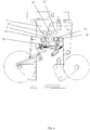
- the compositing device 12 includes a compositing steel roller 13, a first pressing rubber roller 14, a rubber roller bracer 15, a first rubber roller swing arm 16, a fixing fulcrum shaft 17, a back pressure steel roller 18, a second pressing rubber roller 19, a back pressure steel roller bracer 20, a first back pressure steel roller swing arm 21, a second rubber roller swing arm 22, a return tension spring, a first cylinder 23, a second cylinder 24, a positioning flat pin, a rotary sleeve 35 and a positioning screw.
- the compositing steel roller 13 is connected with the second composite frame side 2.
- the first rubber roller swing arm 16 is fixed on both ends of the rubber roller bracer 15.
- the first pressing rubber roller 14 is mounted on the first rubber roller swing arm 16.
- the first back pressure steel roller swing arm 21 is fixed on both ends of the back pressure steel roller bracer 20.
- the first back pressure steel roller 18 is mounted on the first back pressure steel roller swing arm 21.
- the fixing fulcrum shaft 17 is connected with the first back pressure steel roller swing arm 21 through the first rubber roller swing arm 16.
- the ends of the first fixing fulcrum shaft 17 are fixed on the second composite frame side 2.
- the first rubber roller swing arm 16 and the first back pressure steel roller swing arm 21 are rotatable on the fixing fulcrum shaft 17.
- the first rubber roller swing arm 16 is connected with the first back pressure steel roller swing arm 21 by the return tension spring.
- One end of the first cylinder 23 is fixed on the second composite frame side 2.
- the other end of the first cylinder 23 is connected with the first back pressure steel roller swing arm 21.
- the second cylinder 24 is fixed on the second composite frame side 2.
- the other end of the second cylinder 24 is connected with the second rubber roller swing arm 22.
- the second pressing rubber roller 19 is mounted on the second rubber roller swing arm 22.
- the said second pressing rubber roller 19 is at the left end of the compositing steel roller 13.
- the said first back pressure steel roller 18 and the first pressing rubber roller 14 are at the right end of the compositing steel roller 13.
- the rotary sleeve 35 is mounted on the first rubber roller swing arm 16.
- the positioning flat pin is mounted within the rotary sleeve 35.
- the positioning screw is arranged on the first rubber roller swing arm 16 and engaged with the positioning grooves.
- a first guide roller 25, a second guide roller 26 and a third guide roller 27 are arranged above the first back pressure steel roller 18, the compositing steel roller 13, the first pressing rubber roller 14 and the second pressing rubber roller 19 in order from left to right.
- a fourth guide roller 28 is arranged below the compositing steel roller 13.
- the said material-pressing device 10 includes a material-pressing holder 29 and a material-pressing rod 30.
- a material-pressing roller 31 is arranged on one end of the material-pressing rod 30.
- the other end of the material-pressing rod 30 is hinged with the second composite frame side 2.
- the material-pressing holder 29 is connected with the second composite frame side 2.
- a material-pressing cylinder 32 is hinged on the material-pressing holder 29.
- positioning holes 33 arranged on the material-pressing rod 30.
- the driving end of the material-pressing cylinder 32 is connected with one of the positioning holes 33.
- a forward single compositing process, a forward double compositing process and an inverse single compositing process could be realized with the multifunctional compositing machine, thereby meeting different demands in use.
- a first base material on a first unwinding device passes through a first pendulum roller device, the first unwinding tension device 5, the coating mechanism 7, the first coating channel tension-control pendulum roller device 6 and the second guide roller 26 in turn, and then it enters the right side of the composite steal roller 13 of the compositing device 12;
- a second base material on a second unwinding device passes through the second unwinding tension device 11 and the third guide roller 27 in turn, and then it enters the right side of the compositing steel roller 13 of the compositing device 12.
- the first base material and the second base material are composited at the compositing device 12, and then a rewinding is accomplished at a rewinding device.
- a first base material on a first unwinding device passes through a first pendulum roller device, the first unwinding tension device 5, the coating mechanism 7, the first coating channel tension-control pendulum roller device 6 and the second guide roller 26 in turn, and then it enters the right side of the compositing steel roller 13 of the compositing device 12.
- a second base material on a second unwinding device passes through the second unwinding tension device 11 and the third guide roller 27 in turn, and then it enters the right side of the compositing steel roller 13 of the compositing device 12.
- the first base material and the second base material are composited at the right side of the compositing device 12 for the first time, and they are composited at the left side of the compositing device 12 for the second time. Then a rewinding is accomplished at a rewinding device after they pass through the first guide roller 25.
- the problem of a non-uniform glue layer caused by a non-uniform printing film, by an insufficient leveling of the glue or by some defects existing on the first pressing rubber roller 14 could be solved through two compositing processes with the first pressing rubber roller 14 and the second pressing rubber roller 19. As a result, a double insurance effect could be realized.
- a first base material on a first unwinding device passes through a first pendulum roller device, the first unwinding tension device 5, the coating mechanism 7, the first coating channel tension-control pendulum roller device 6 and the second guide roller 26 in turn, and then it enters the left side of the compositing steel roller 13 of the compositing device 12.
- a second base material on a second unwinding device passes through the second unwinding tension device 11 and the third guide roller 27 in turn, and then it enters the left side of the compositing steel roller 13 of the compositing device 12. Make the compositing steel roller 13 and the second pressing rubber roller 19 rotate in opposite direction.
- the first base material and the second base material are composited at the left side of the compositing device 12 and pass through the fourth guide roller 28, and then a rewinding is accomplished at a rewinding device.
- the base material on the second unwinding mechanism 8 is aluminum foil
- the unevenness existing on the film of the first unwinding mechanism 4 can be passed to the aluminum foil by contacting with the compositing steel roller 13.
- this unevenness on the aluminum foil could be solved by the inverse single compositing process.
- the present invention further comprises a compositing method of the multifunctional compositing machine comprising: a forward single compositing process, a forward double compositing process and an inverse single compositing process.
- the forward single compositing process comprising the following steps:
- the forward double compositing process comprising the following steps:
- the inverse single compositing process comprising the following steps:
Landscapes
- Physics & Mathematics (AREA)
- Fluid Mechanics (AREA)
- Lining Or Joining Of Plastics Or The Like (AREA)
- Coating Apparatus (AREA)
- Application Of Or Painting With Fluid Materials (AREA)
Abstract
Description
- The present invention relates to a multifunctional compositing machine and compositing method thereof.
- At present when base material is composited via a compositing machine, there may be an uneven glue layer if much roughness exists on the base material. If the glue couldn't be leveled sufficiently, or some defects exist on the compositing rubber roller, the non-uniform glue layer occurs as well.
- The technical problem to be solved by the present invention is to provide a multifunctional compositing machine with a reasonable structural design, which could fulfill various compounding requirements.
- To solve the above mentioned technical problems, the present invention comprises a frame, the frame comprising a first composite frame side, a second composite frame side and a frame top arranged on the top of the first frame side and the second composite frame side;
a first unwinding mechanism, a first unwinding tension device, a first coating channel tension-control pendulum roller device and a coating mechanism being arranged on the first composite frame side;
a second unwinding mechanism, a rewinding mechanism, a material-pressing device, a second unwinding tension device and a compositing device being arranged on the second composite frame side;
the compositing device comprising a compositing steel roller, a first pressing rubber roller, a rubber roller bracer, a first rubber roller swing arm, a fixing fulcrum shaft, a first back pressure steel roller, a second pressing rubber roller, a back pressure steel roller bracer, a first back pressure steel roller swing arm, a second rubber roller swing arm, a return tension spring, a first cylinder and a second cylinder,
the compositing steel roller being connected with the second composite frame side, the first rubber roller swing arm being fixed on both ends of the rubber roller bracer, the first pressing rubber roller being mounted on the first rubber roller swing arm, the first back pressure steel roller swing arm being fixed on both ends of the back pressure steel roller bracer, the first back pressure steel roller being mounted on the first back pressure steel roller swing arm, the fixing fulcrum shaft being connected with the first back pressure steel roller swing arm through the first rubber roller swing arm, the ends of the first fixing fulcrum shaft being fixed on the second composite frame side, the first rubber roller swing arm and the first back pressure steel roller swing arm being rotatable on the fixing fulcrum shaft, the first rubber roller swing arm being connected with the first back steel roller swing arm by the return tension spring, one end of the first cylinder being fixed on the second composite frame side, the other end of the first cylinder being connected with the first back pressure steel roller swing arm, one end of the second cylinder being fixed on the second composite frame side, the other end of the second cylinder being connected with the second rubber roller swing arm, the second pressing rubber roller being mounted on the second rubber roller swing arm, the second pressing rubber roller being at the left end of the compositing steel roller, the first back pressure steel roller and the first pressing rubber roller being at the right end of the compositing steel roller;
a first guide roller, a second guide roller and a third guide roller being arranged above the first back pressure steel roller, the compositing steel roller, the first pressing rubber roller and the second pressing rubber roller in order from left to right, a fourth guide roller being arranged below the compositing steel roller. - As a further improvement of the present invention, the compositing device further comprises a positioning flat pin, a rotary sleeve and a positioning screw,
the rotary sleeve being mounted on the first rubber roller swing arm, the positioning flat pin being mounted within the rotary sleeve, more than two positioning grooves being arranged on the rotary sleeve, the positioning crew being arranged on the first rubber roller swing arm and engaged with the positioning grooves. - As a further improvement of the present invention, the material-pressing device comprises a material-pressing holder and a material-pressing rod,
a material-pressing roller being arranged on one end of the material-pressing rod, the other end of the material-pressing rod being hinged with the second composite frame side, the material-pressing holder being connected with the second composite frame side, a material-pressing cylinder being hinged on the material-pressing holder, a number of positioning holes being arranged on the material-pressing rod, the driving end of the material-pressing cylinder being connected with one of the positioning hole. - As a further improvement of the present invention, a number of wide slot two-way partial guide roller are arranged on the first composite frame side, the second composite frame side and the frame top.
- The advantageous effects of the present invention lie in that a forward single compositing process, a forward double compositing process and an inverse single compositing process could be realized with the multifunctional compositing machine, thereby meeting different demands in use.
- The present invention further comprises a compositing method of the multifunctional compositing machine, comprising a forward single compositing process, a forward double compositing process and an inverse single compositing process;
the forward single compositing process comprising the following steps: - A1. making a first base material on a first unwinding device pass through a first pendulum roller device, a first unwinding tension device, a coating mechanism, a first coating channel tension-control pendulum roller device and a second guide roller in turn, and then making it enter the right side of a compositing steel roller of a compositing device;
- B1. making a second base material on a second unwinding device pass through a second unwinding tension device and a third guide roller in turn, and then making it enter the right side of the compositing steel roller of the compositing device;
- C1. accomplishing a rewinding at a rewinding device after the first base material and the second base material are composited at the compositing device;
- A2. making a first base material on a first unwinding device pass through a first pendulum roller device, a first unwinding tension device, a coating mechanism, a first coating channel tension-control pendulum roller device, and a second guide roller in turn, and then making it enter the right side of a compositing steel roller of a compositing device;
- B2. making a second base material on a second unwinding device pass through a second unwinding tension device and a third guide roller in turn, and then making it enter the right side of the compositing steel roller of the compositing device;
- C2. compositing the first base material and the second base material for the first time at the left side of the compositing device and compositing them for the second time at the right side of the compositing device, and then accomplishing a rewinding at a rewinding device after they pass through a first guide roller;
- A3. making a first base material on a first unwinding device pass through a first pendulum roller device, a first unwinding tension device, a coating mechanism, a first coating channel tension-control pendulum roller device, and a second guide roller in turn, and then making it enter the left side of a compositing steel roller of a compositing device;
- B3. making a second base material on a second unwinding device pass through a second unwinding tension device and a third guide roller in turn, and then making it enter the left side of the compositing steel roller of the compositing device;
- C3. making the compositing steel roller and the second pressing rubber roller to rotate in opposite direction, compositing the first base material and the second base material at the left side of the compositing device, and then accomplishing a rewinding at a rewinding device after they pass through a fourth guide roller.
-
-
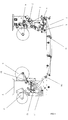
Fig.1 is a schematic diagram of the present invention. -
Fig.2 is a layout of a first base material and a second base material on a second composite frame side if performing a forward single compositing process in the present invention. -
Fig.3 is a layout of a first base material and a second base material on a second composite frame side if performing a forward double compositing process in the present invention. -
Fig. 4 is a layout of a first base material and a second base material on a second composite frame side if performing an inverse single compositing process in the present invention. - Further illustration on the present invention will be given in the following in conjunction with drawings
- As shown in
Fig. 1 to Fig. 4 , the present invention includes a frame. The frame includes a first composite frame side 1, a secondcomposite frame side 2 and aframe top 3 arranged on the top of the first frame side 1 and the secondcomposite frame side 2. Afirst unwinding mechanism 4, a firstunwinding tension device 5, a first coating channel tension-controlpendulum roller device 6 and acoating mechanism 7 are arranged on the first composite frame side 1. Asecond unwinding mechanism 8, arewinding mechanism 9, a material-pressing device 10, a secondunwinding tension device 11 and a compositingdevice 12 are arranged on the secondcomposite frame side 2. The compositingdevice 12 includes a compositingsteel roller 13, a first pressingrubber roller 14, arubber roller bracer 15, a first rubberroller swing arm 16, afixing fulcrum shaft 17, a backpressure steel roller 18, a second pressingrubber roller 19, a back pressuresteel roller bracer 20, a first back pressure steelroller swing arm 21, a second rubberroller swing arm 22, a return tension spring, afirst cylinder 23, asecond cylinder 24, a positioning flat pin, arotary sleeve 35 and a positioning screw. The compositingsteel roller 13 is connected with the secondcomposite frame side 2. The first rubberroller swing arm 16 is fixed on both ends of therubber roller bracer 15. The first pressingrubber roller 14 is mounted on the first rubberroller swing arm 16. The first back pressure steelroller swing arm 21 is fixed on both ends of the back pressuresteel roller bracer 20. The first backpressure steel roller 18 is mounted on the first back pressure steelroller swing arm 21. Thefixing fulcrum shaft 17 is connected with the first back pressure steelroller swing arm 21 through the first rubberroller swing arm 16. The ends of the firstfixing fulcrum shaft 17 are fixed on the secondcomposite frame side 2. The first rubberroller swing arm 16 and the first back pressure steelroller swing arm 21 are rotatable on the fixingfulcrum shaft 17. The first rubberroller swing arm 16 is connected with the first back pressure steelroller swing arm 21 by the return tension spring. One end of thefirst cylinder 23 is fixed on the secondcomposite frame side 2. The other end of thefirst cylinder 23 is connected with the first back pressure steelroller swing arm 21. One end of thesecond cylinder 24 is fixed on the secondcomposite frame side 2. The other end of thesecond cylinder 24 is connected with the second rubberroller swing arm 22. The secondpressing rubber roller 19 is mounted on the second rubberroller swing arm 22. The said secondpressing rubber roller 19 is at the left end of the compositingsteel roller 13. The said first backpressure steel roller 18 and the firstpressing rubber roller 14 are at the right end of the compositingsteel roller 13. Therotary sleeve 35 is mounted on the first rubberroller swing arm 16. The positioning flat pin is mounted within therotary sleeve 35. There are more than two positioning grooves arranged on therotary sleeve 35. The positioning screw is arranged on the first rubberroller swing arm 16 and engaged with the positioning grooves. Afirst guide roller 25, asecond guide roller 26 and athird guide roller 27 are arranged above the first backpressure steel roller 18, the compositingsteel roller 13, the firstpressing rubber roller 14 and the secondpressing rubber roller 19 in order from left to right. Afourth guide roller 28 is arranged below the compositingsteel roller 13. The said material-pressingdevice 10 includes a material-pressingholder 29 and a material-pressingrod 30. A material-pressingroller 31 is arranged on one end of the material-pressingrod 30. The other end of the material-pressingrod 30 is hinged with the secondcomposite frame side 2. The material-pressingholder 29 is connected with the secondcomposite frame side 2. A material-pressingcylinder 32 is hinged on the material-pressingholder 29. There are a number of positioning holes 33 arranged on the material-pressingrod 30. The driving end of the material-pressingcylinder 32 is connected with one of the positioning holes 33. There are a number of wide slot two-waypartial guide roller 34 arranged on the first composite frame side 1, the secondcomposite frame side 2 and theframe top 3. - A forward single compositing process, a forward double compositing process and an inverse single compositing process could be realized with the multifunctional compositing machine, thereby meeting different demands in use. In the forward single compositing process, a first base material on a first unwinding device passes through a first pendulum roller device, the first
unwinding tension device 5, thecoating mechanism 7, the first coating channel tension-controlpendulum roller device 6 and thesecond guide roller 26 in turn, and then it enters the right side of thecomposite steal roller 13 of thecompositing device 12; a second base material on a second unwinding device passes through the secondunwinding tension device 11 and thethird guide roller 27 in turn, and then it enters the right side of the compositingsteel roller 13 of thecompositing device 12. The first base material and the second base material are composited at thecompositing device 12, and then a rewinding is accomplished at a rewinding device. In a forward double compositing process, a first base material on a first unwinding device passes through a first pendulum roller device, the firstunwinding tension device 5, thecoating mechanism 7, the first coating channel tension-controlpendulum roller device 6 and thesecond guide roller 26 in turn, and then it enters the right side of the compositingsteel roller 13 of thecompositing device 12. A second base material on a second unwinding device passes through the secondunwinding tension device 11 and thethird guide roller 27 in turn, and then it enters the right side of the compositingsteel roller 13 of thecompositing device 12. The first base material and the second base material are composited at the right side of thecompositing device 12 for the first time, and they are composited at the left side of thecompositing device 12 for the second time. Then a rewinding is accomplished at a rewinding device after they pass through thefirst guide roller 25. In the forward double compositing process, the problem of a non-uniform glue layer caused by a non-uniform printing film, by an insufficient leveling of the glue or by some defects existing on the firstpressing rubber roller 14 could be solved through two compositing processes with the firstpressing rubber roller 14 and the secondpressing rubber roller 19. As a result, a double insurance effect could be realized. In an inverse single compositing process, a first base material on a first unwinding device passes through a first pendulum roller device, the firstunwinding tension device 5, thecoating mechanism 7, the first coating channel tension-controlpendulum roller device 6 and thesecond guide roller 26 in turn, and then it enters the left side of the compositingsteel roller 13 of thecompositing device 12. A second base material on a second unwinding device passes through the secondunwinding tension device 11 and thethird guide roller 27 in turn, and then it enters the left side of the compositingsteel roller 13 of the compositing device 12. Make the compositingsteel roller 13 and the secondpressing rubber roller 19 rotate in opposite direction. The first base material and the second base material are composited at the left side of thecompositing device 12 and pass through thefourth guide roller 28, and then a rewinding is accomplished at a rewinding device. If the base material on thesecond unwinding mechanism 8 is aluminum foil, the unevenness existing on the film of thefirst unwinding mechanism 4 can be passed to the aluminum foil by contacting with the compositingsteel roller 13. However this unevenness on the aluminum foil could be solved by the inverse single compositing process. - The present invention further comprises a compositing method of the multifunctional compositing machine comprising: a forward single compositing process, a forward double compositing process and an inverse single compositing process.
- The forward single compositing process comprising the following steps:
- A1. making a first base material on a first unwinding device pass through a first pendulum roller device, a first unwinding tension device, a coating mechanism, a first coating channel tension-control pendulum roller device and a second guide roller in turn, and then making it enter the right side of a compositing steel roller of a compositing device;
- B1. making a second base material on a second unwinding device pass through a second unwinding tension device and a third guide roller in turn, and then making it enter the right side of the compositing steel roller of the compositing device;
- C1. accomplishing a rewinding at a rewinding device after the first base material and the second base material are composited at the compositing device.
- The forward double compositing process comprising the following steps:
- A2. making a first base material on a first unwinding device pass through a first pendulum roller device, a first unwinding tension device, a coating mechanism, a first coating channel tension-control pendulum roller device, and a second guide roller in turn, and then making it enter the right side of a compositing steel roller of a compositing device;
- B2. making a second base material on a second unwinding device pass through a second unwinding tension device and a third guide roller in turn, and then making it enter the right side of the compositing steel roller of the compositing device;
- C2. compositing the first base material and the second base material for the first time at the left side of the compositing device and compositing them for the second time at the right side of the compositing device, and then accomplishing a rewinding at a rewinding device after they pass through a first guide roller.
- The inverse single compositing process comprising the following steps:
- A3. making a first base material on a first unwinding device pass through a first pendulum roller device, a first unwinding tension device, a coating mechanism, a first coating channel tension-control pendulum roller device, and a second guide roller in turn, and then making it enter the left side of a compositing steel roller of a compositing device;
- B3. making a second base material on a second unwinding device pass through a second unwinding tension device and a third guide roller in turn, and then making it enter the left side of the compositing steel roller of the compositing device;
- C3. making the compositing steel roller and the second pressing rubber roller to rotate in opposite direction, compositing the first base material and the second base material at the left side of the compositing device, and then accomplishing a rewinding at a rewinding device after they pass through a fourth guide roller.
Claims (5)
- A multifunctional compositing machine, characterized by comprising a frame, the frame comprising a first composite frame side, a second composite frame side and a frame top arranged on the top of the first frame side and the second composite frame side;
a first unwinding mechanism, a first unwinding tension device, a first coating channel tension-control pendulum roller device and a coating mechanism being arranged on the first composite frame side;
a second unwinding mechanism, a rewinding mechanism, a material-pressing device, a second unwinding tension device and a compositing device being arranged on the second composite frame side;
the compositing device comprising a compositing steel roller, a first pressing rubber roller, a rubber roller bracer, a first rubber roller swing arm, a fixing fulcrum shaft, a first back pressure steel roller, a second pressing rubber roller, a back pressure steel roller bracer, a first back pressure steel roller swing arm, a second rubber roller swing arm, a return tension spring, a first cylinder and a second cylinder,
the compositing steel roller being connected with the second composite frame side, the first rubber roller swing arm being fixed on both ends of the rubber roller bracer, the first pressing rubber roller being mounted on the first rubber roller swing arm, the first back pressure steel roller swing arm being fixed on both ends of the back pressure steel roller bracer, the first back pressure steel roller being mounted on the first back pressure steel roller swing arm, the fixing fulcrum shaft being connected with the first back pressure steel roller swing arm through the first rubber roller swing arm, the ends of the first fixing fulcrum shaft being fixed on the second composite frame side, the first rubber roller swing arm and the first back pressure steel roller swing arm being rotatable on the fixing fulcrum shaft, the first rubber roller swing arm being connected with the first back steel roller swing arm by the return tension spring, one end of the first cylinder being fixed on the second composite frame side, the other end of the first cylinder being connected with the first back pressure steel roller swing arm, one end of the second cylinder being fixed on the second composite frame side, the other end of the second cylinder being connected with the second rubber roller swing arm, the second pressing rubber roller being mounted on the second rubber roller swing arm, the second pressing rubber roller being at the left end of the compositing steel roller, the first back pressure steel roller and the first pressing rubber roller being at the right end of the compositing steel roller;
a first guide roller, a second guide roller and a third guide roller being arranged above the first back pressure steel roller, the compositing steel roller, the first pressing rubber roller and the second pressing rubber roller in order from left to right, a fourth guide roller being arranged below the compositing steel roller. - The multifunctional compositing machine as recited in claim 1, characterized in that the compositing device further comprises a positioning flat pin, a rotary sleeve and a positioning screw,
the rotary sleeve being mounted on the first rubber roller swing arm, the positioning flat pin being mounted within the rotary sleeve, more than two positioning grooves being arranged on the rotary sleeve, the positioning crew being arranged on the first rubber roller swing arm and engaged with the positioning grooves. - The multifunctional compositing machine as recited in claim 1, characterized in that the material-pressing device comprises a material-pressing holder and a material-pressing rod,
a material-pressing roller being arranged on one end of the material-pressing rod, the other end of the material-pressing rod being hinged with the second composite frame side, the material-pressing holder being connected with the second composite frame side, a material-pressing cylinder being hinged on the material-pressing holder, a number of positioning holes being arranged on the material-pressing rod, the driving end of the material-pressing cylinder being connected with one of the positioning hole. - The multifunctional compositing machine as recited in claim 1, characterized in that a number of wide slot two-way partial guide roller are arranged on the first composite frame side, the second composite frame side and the frame top.
- A compositing method of the multifunctional of a compositing machine characterized in that the method comprises a forward single compositing process, a forward double compositing process and an inverse single compositing process;
the forward single compositing process comprising the following steps:A1. making a first base material on a first unwinding device pass through a first pendulum roller device, a first unwinding tension device, a coating mechanism, a first coating channel tension-control pendulum roller device and a second guide roller in turn, and then making it enter the right side of a compositing steel roller of a compositing device;B1. making a second base material on a second unwinding device pass through a second unwinding tension device and a third guide roller in turn, and then making it enter the right side of the compositing steel roller of the compositing device;C1. accomplishing a rewinding at a rewinding device after the first base material and the second base material are composited at the compositing device;the forward double compositing process comprising the following steps:A2. making a first base material on a first unwinding device pass through a first pendulum roller device, a first unwinding tension device, a coating mechanism, a first coating channel tension-control pendulum roller device, and a second guide roller in turn, and then making it enter the right side of a compositing steel roller of a compositing device;B2. making a second base material on a second unwinding device pass through a second unwinding tension device and a third guide roller in turn, and then making it enter the right side of the compositing steel roller of the compositing device;C2. compositing the first base material and the second base material for the first time at the left side of the compositing device and compositing them for the second time at the right side of the compositing device, and then accomplishing a rewinding at a rewinding device after they pass through a first guide roller;the inverse single compositing process comprising the following steps:A3. making a first base material on a first unwinding device pass through a first pendulum roller device, a first unwinding tension device, a coating mechanism, a first coating channel tension-control pendulum roller device, and a second guide roller in turn, and then making it enter the left side of a compositing steel roller of a compositing device;B3. making a second base material on a second unwinding device pass through a second unwinding tension device and a third guide roller in turn, and then making it enter the left side of the compositing steel roller of the compositing device;C3. making the compositing steel roller and the second pressing rubber roller to rotate in opposite direction, compositing the first base material and the second base material at the left side of the compositing device, and then accomplishing a rewinding at a rewinding device after they pass through a fourth guide roller.
Priority Applications (1)
| Application Number | Priority Date | Filing Date | Title |
|---|---|---|---|
| PL18803519T PL3536498T3 (en) | 2018-01-19 | 2018-03-12 | Multifunctional laminating machine and laminating method |
Applications Claiming Priority (2)
| Application Number | Priority Date | Filing Date | Title |
|---|---|---|---|
| CN201810053573.9A CN108099352A (en) | 2018-01-19 | 2018-01-19 | A kind of multi-function peripheral and its complex method |
| PCT/CN2018/078694 WO2019140766A1 (en) | 2018-01-19 | 2018-03-12 | Multifunctional compound machine and compound method thereof |
Publications (3)
| Publication Number | Publication Date |
|---|---|
| EP3536498A1 true EP3536498A1 (en) | 2019-09-11 |
| EP3536498A4 EP3536498A4 (en) | 2020-02-26 |
| EP3536498B1 EP3536498B1 (en) | 2021-09-22 |
Family
ID=62220043
Family Applications (1)
| Application Number | Title | Priority Date | Filing Date |
|---|---|---|---|
| EP18803519.0A Active EP3536498B1 (en) | 2018-01-19 | 2018-03-12 | Multifunctional laminating machine and laminating method |
Country Status (5)
| Country | Link |
|---|---|
| EP (1) | EP3536498B1 (en) |
| CN (1) | CN108099352A (en) |
| ES (1) | ES2901472T3 (en) |
| PL (1) | PL3536498T3 (en) |
| WO (1) | WO2019140766A1 (en) |
Families Citing this family (6)
| Publication number | Priority date | Publication date | Assignee | Title |
|---|---|---|---|---|
| CN109334210B (en) * | 2018-11-21 | 2024-07-30 | 广州通泽机械有限公司 | Composite technology and composite unit with variable path, reference and driving relation |
| CN110901213A (en) * | 2019-12-18 | 2020-03-24 | 辛格顿(常州)新材料科技有限公司 | Pressure-sensitive adhesive laminating device and laminating method |
| CN111331997B (en) * | 2020-04-16 | 2022-05-27 | 广州通泽机械有限公司 | Three-in-one solvent-free compound machine and compound method |
| CN114043806A (en) * | 2021-10-27 | 2022-02-15 | 洛阳帝然特医药包装材料有限公司 | Production device for medical packaging aluminum foil |
| CN114030265A (en) * | 2021-12-03 | 2022-02-11 | 广东厚海环保新材料有限公司 | Three-in-one gluing compound machine for non-woven fabric |
| CN119952959B (en) * | 2023-11-08 | 2025-11-28 | 厦门文仪电脑材料有限公司 | A membrane composite mechanism |
Family Cites Families (8)
| Publication number | Priority date | Publication date | Assignee | Title |
|---|---|---|---|---|
| US6912040B2 (en) * | 2003-04-30 | 2005-06-28 | Hewlett-Packard Development Company, Lp. | Photofinishers |
| CN101259772B (en) * | 2008-04-29 | 2010-06-09 | 广州通泽机械有限公司 | Solvent-free composite machine |
| CN205522870U (en) * | 2016-04-08 | 2016-08-31 | 浙江绿净环保科技有限公司 | High -efficient polytetrafluoroethylene lamination set composite |
| CN106183349B (en) * | 2016-08-30 | 2018-11-02 | 广州通泽机械有限公司 | A kind of double mode coating solvent-free composite machine and double mode are coated with solvent-free recombiner unit |
| CN206456063U (en) * | 2016-10-21 | 2017-09-01 | 广东恒生彩印有限公司机械分公司 | A kind of flexible package quick-dry type cuts solvent-free equipment complex automatically |
| CN107244131A (en) * | 2017-06-06 | 2017-10-13 | 上海大城包装材料有限公司 | A kind of dual-purpose compounding machine of novel solvent-free |
| CN107283997A (en) * | 2017-08-04 | 2017-10-24 | 广州通泽机械有限公司 | A kind of four layers of compounding machine |
| CN107498980B (en) * | 2017-09-18 | 2020-02-28 | 广州通泽机械有限公司 | Double-coating solvent-free compound machine and compound method thereof |
-
2018
- 2018-01-19 CN CN201810053573.9A patent/CN108099352A/en active Pending
- 2018-03-12 WO PCT/CN2018/078694 patent/WO2019140766A1/en not_active Ceased
- 2018-03-12 PL PL18803519T patent/PL3536498T3/en unknown
- 2018-03-12 EP EP18803519.0A patent/EP3536498B1/en active Active
- 2018-03-12 ES ES18803519T patent/ES2901472T3/en active Active
Also Published As
| Publication number | Publication date |
|---|---|
| EP3536498A4 (en) | 2020-02-26 |
| WO2019140766A1 (en) | 2019-07-25 |
| PL3536498T3 (en) | 2022-04-04 |
| ES2901472T3 (en) | 2022-03-22 |
| CN108099352A (en) | 2018-06-01 |
| EP3536498B1 (en) | 2021-09-22 |
Similar Documents
| Publication | Publication Date | Title |
|---|---|---|
| EP3536498A1 (en) | Multifunctional compound machine and compound method thereof | |
| CN101522548A (en) | Automatic film winding device, slitting and winding system, and method of producing rolled film | |
| CN109955311A (en) | A copper foil cutting machine | |
| CN219303722U (en) | Coating tool | |
| CN205892298U (en) | Gravure press receive and releases a roll book footpath measuring device | |
| CN101367477B (en) | Winding and material-pressing mechanism of grade checking machine | |
| CN105151862A (en) | Device for reeling super-thin paper | |
| CN111392473B (en) | Automatic roll changing continuous film laminating equipment of flexo printing machine | |
| CN110254875A (en) | Efficient cardboard labeling equipment | |
| CN109516266B (en) | Membrane material smoothing device | |
| CN204822304U (en) | Automatic tension control system is rolled up to label of rubberizing machine | |
| CN209701917U (en) | A kind of pressure roller automatic retracted regulating mechanism of winder | |
| CN211756602U (en) | Coating structure of coating machine | |
| CN110303762A (en) | A fabric printing device capable of precise positioning and its working method | |
| CN207758182U (en) | Shielding film with double adhesive tape fixed mechanism winds glue plastering machine | |
| CN205294388U (en) | Receipts material compression roller device on printing machine | |
| CN103708256B (en) | A kind of a homogeneous example showing an inverse connection between the middle term and the major term volume equipment | |
| CN207643693U (en) | The adjustable ventilated membrane in gap stretches roller arrangement | |
| CN211165760U (en) | Solvent-free laminating machine for windowed kraft paper | |
| CN201566207U (en) | Upper and lower plate transmission mechanism of direct plate making machine | |
| CN206763283U (en) | A kind of coating machine double spread apparatus for fast switching | |
| CN117184599B (en) | Winding device and labeling device of winding machine | |
| CN223303810U (en) | Prevent loose protection film coiling mechanism | |
| CN217021428U (en) | Transfer type hard backboard roller pasting film covering equipment integrated with consumable quick-change mechanism | |
| CN110561886A (en) | Solvent-free laminating machine for windowed kraft paper |
Legal Events
| Date | Code | Title | Description |
|---|---|---|---|
| STAA | Information on the status of an ep patent application or granted ep patent |
Free format text: STATUS: UNKNOWN |
|
| STAA | Information on the status of an ep patent application or granted ep patent |
Free format text: STATUS: THE INTERNATIONAL PUBLICATION HAS BEEN MADE |
|
| PUAI | Public reference made under article 153(3) epc to a published international application that has entered the european phase |
Free format text: ORIGINAL CODE: 0009012 |
|
| STAA | Information on the status of an ep patent application or granted ep patent |
Free format text: STATUS: REQUEST FOR EXAMINATION WAS MADE |
|
| 17P | Request for examination filed |
Effective date: 20181127 |
|
| AK | Designated contracting states |
Kind code of ref document: A1 Designated state(s): AL AT BE BG CH CY CZ DE DK EE ES FI FR GB GR HR HU IE IS IT LI LT LU LV MC MK MT NL NO PL PT RO RS SE SI SK SM TR |
|
| AX | Request for extension of the european patent |
Extension state: BA ME |
|
| A4 | Supplementary search report drawn up and despatched |
Effective date: 20200127 |
|
| RIC1 | Information provided on ipc code assigned before grant |
Ipc: B32B 37/10 20060101AFI20200121BHEP Ipc: B32B 37/20 20060101ALN20200121BHEP Ipc: B32B 41/00 20060101ALI20200121BHEP |
|
| RIC1 | Information provided on ipc code assigned before grant |
Ipc: B32B 37/10 20060101AFI20210202BHEP Ipc: B32B 37/20 20060101ALN20210202BHEP Ipc: B32B 41/00 20060101ALI20210202BHEP |
|
| GRAP | Despatch of communication of intention to grant a patent |
Free format text: ORIGINAL CODE: EPIDOSNIGR1 |
|
| STAA | Information on the status of an ep patent application or granted ep patent |
Free format text: STATUS: GRANT OF PATENT IS INTENDED |
|
| DAV | Request for validation of the european patent (deleted) | ||
| DAX | Request for extension of the european patent (deleted) | ||
| INTG | Intention to grant announced |
Effective date: 20210315 |
|
| RIC1 | Information provided on ipc code assigned before grant |
Ipc: B32B 37/10 20060101AFI20210301BHEP Ipc: B32B 37/20 20060101ALN20210301BHEP Ipc: B32B 41/00 20060101ALI20210301BHEP |
|
| GRAJ | Information related to disapproval of communication of intention to grant by the applicant or resumption of examination proceedings by the epo deleted |
Free format text: ORIGINAL CODE: EPIDOSDIGR1 |
|
| STAA | Information on the status of an ep patent application or granted ep patent |
Free format text: STATUS: REQUEST FOR EXAMINATION WAS MADE |
|
| RIN1 | Information on inventor provided before grant (corrected) |
Inventor name: LI, JUNHONG |
|
| GRAP | Despatch of communication of intention to grant a patent |
Free format text: ORIGINAL CODE: EPIDOSNIGR1 |
|
| STAA | Information on the status of an ep patent application or granted ep patent |
Free format text: STATUS: GRANT OF PATENT IS INTENDED |
|
| INTC | Intention to grant announced (deleted) | ||
| RIC1 | Information provided on ipc code assigned before grant |
Ipc: B32B 37/20 20060101ALN20210527BHEP Ipc: B32B 41/00 20060101ALI20210527BHEP Ipc: B32B 37/10 20060101AFI20210527BHEP |
|
| INTG | Intention to grant announced |
Effective date: 20210610 |
|
| GRAS | Grant fee paid |
Free format text: ORIGINAL CODE: EPIDOSNIGR3 |
|
| GRAA | (expected) grant |
Free format text: ORIGINAL CODE: 0009210 |
|
| STAA | Information on the status of an ep patent application or granted ep patent |
Free format text: STATUS: THE PATENT HAS BEEN GRANTED |
|
| AK | Designated contracting states |
Kind code of ref document: B1 Designated state(s): AL AT BE BG CH CY CZ DE DK EE ES FI FR GB GR HR HU IE IS IT LI LT LU LV MC MK MT NL NO PL PT RO RS SE SI SK SM TR |
|
| REG | Reference to a national code |
Ref country code: GB Ref legal event code: FG4D |
|
| REG | Reference to a national code |
Ref country code: IE Ref legal event code: FG4D |
|
| REG | Reference to a national code |
Ref country code: DE Ref legal event code: R096 Ref document number: 602018024040 Country of ref document: DE |
|
| REG | Reference to a national code |
Ref country code: CH Ref legal event code: EP Ref country code: AT Ref legal event code: REF Ref document number: 1432002 Country of ref document: AT Kind code of ref document: T Effective date: 20211015 |
|
| REG | Reference to a national code |
Ref country code: LT Ref legal event code: MG9D |
|
| REG | Reference to a national code |
Ref country code: NL Ref legal event code: MP Effective date: 20210922 |
|
| PG25 | Lapsed in a contracting state [announced via postgrant information from national office to epo] |
Ref country code: RS Free format text: LAPSE BECAUSE OF FAILURE TO SUBMIT A TRANSLATION OF THE DESCRIPTION OR TO PAY THE FEE WITHIN THE PRESCRIBED TIME-LIMIT Effective date: 20210922 Ref country code: SE Free format text: LAPSE BECAUSE OF FAILURE TO SUBMIT A TRANSLATION OF THE DESCRIPTION OR TO PAY THE FEE WITHIN THE PRESCRIBED TIME-LIMIT Effective date: 20210922 Ref country code: HR Free format text: LAPSE BECAUSE OF FAILURE TO SUBMIT A TRANSLATION OF THE DESCRIPTION OR TO PAY THE FEE WITHIN THE PRESCRIBED TIME-LIMIT Effective date: 20210922 Ref country code: FI Free format text: LAPSE BECAUSE OF FAILURE TO SUBMIT A TRANSLATION OF THE DESCRIPTION OR TO PAY THE FEE WITHIN THE PRESCRIBED TIME-LIMIT Effective date: 20210922 Ref country code: LT Free format text: LAPSE BECAUSE OF FAILURE TO SUBMIT A TRANSLATION OF THE DESCRIPTION OR TO PAY THE FEE WITHIN THE PRESCRIBED TIME-LIMIT Effective date: 20210922 Ref country code: BG Free format text: LAPSE BECAUSE OF FAILURE TO SUBMIT A TRANSLATION OF THE DESCRIPTION OR TO PAY THE FEE WITHIN THE PRESCRIBED TIME-LIMIT Effective date: 20211222 Ref country code: NO Free format text: LAPSE BECAUSE OF FAILURE TO SUBMIT A TRANSLATION OF THE DESCRIPTION OR TO PAY THE FEE WITHIN THE PRESCRIBED TIME-LIMIT Effective date: 20211222 |
|
| REG | Reference to a national code |
Ref country code: AT Ref legal event code: MK05 Ref document number: 1432002 Country of ref document: AT Kind code of ref document: T Effective date: 20210922 |
|
| PG25 | Lapsed in a contracting state [announced via postgrant information from national office to epo] |
Ref country code: LV Free format text: LAPSE BECAUSE OF FAILURE TO SUBMIT A TRANSLATION OF THE DESCRIPTION OR TO PAY THE FEE WITHIN THE PRESCRIBED TIME-LIMIT Effective date: 20210922 Ref country code: GR Free format text: LAPSE BECAUSE OF FAILURE TO SUBMIT A TRANSLATION OF THE DESCRIPTION OR TO PAY THE FEE WITHIN THE PRESCRIBED TIME-LIMIT Effective date: 20211223 |
|
| REG | Reference to a national code |
Ref country code: ES Ref legal event code: FG2A Ref document number: 2901472 Country of ref document: ES Kind code of ref document: T3 Effective date: 20220322 |
|
| PG25 | Lapsed in a contracting state [announced via postgrant information from national office to epo] |
Ref country code: AT Free format text: LAPSE BECAUSE OF FAILURE TO SUBMIT A TRANSLATION OF THE DESCRIPTION OR TO PAY THE FEE WITHIN THE PRESCRIBED TIME-LIMIT Effective date: 20210922 |
|
| PG25 | Lapsed in a contracting state [announced via postgrant information from national office to epo] |
Ref country code: IS Free format text: LAPSE BECAUSE OF FAILURE TO SUBMIT A TRANSLATION OF THE DESCRIPTION OR TO PAY THE FEE WITHIN THE PRESCRIBED TIME-LIMIT Effective date: 20220122 Ref country code: SK Free format text: LAPSE BECAUSE OF FAILURE TO SUBMIT A TRANSLATION OF THE DESCRIPTION OR TO PAY THE FEE WITHIN THE PRESCRIBED TIME-LIMIT Effective date: 20210922 Ref country code: RO Free format text: LAPSE BECAUSE OF FAILURE TO SUBMIT A TRANSLATION OF THE DESCRIPTION OR TO PAY THE FEE WITHIN THE PRESCRIBED TIME-LIMIT Effective date: 20210922 Ref country code: PT Free format text: LAPSE BECAUSE OF FAILURE TO SUBMIT A TRANSLATION OF THE DESCRIPTION OR TO PAY THE FEE WITHIN THE PRESCRIBED TIME-LIMIT Effective date: 20220124 Ref country code: NL Free format text: LAPSE BECAUSE OF FAILURE TO SUBMIT A TRANSLATION OF THE DESCRIPTION OR TO PAY THE FEE WITHIN THE PRESCRIBED TIME-LIMIT Effective date: 20210922 Ref country code: EE Free format text: LAPSE BECAUSE OF FAILURE TO SUBMIT A TRANSLATION OF THE DESCRIPTION OR TO PAY THE FEE WITHIN THE PRESCRIBED TIME-LIMIT Effective date: 20210922 Ref country code: CZ Free format text: LAPSE BECAUSE OF FAILURE TO SUBMIT A TRANSLATION OF THE DESCRIPTION OR TO PAY THE FEE WITHIN THE PRESCRIBED TIME-LIMIT Effective date: 20210922 Ref country code: AL Free format text: LAPSE BECAUSE OF FAILURE TO SUBMIT A TRANSLATION OF THE DESCRIPTION OR TO PAY THE FEE WITHIN THE PRESCRIBED TIME-LIMIT Effective date: 20210922 |
|
| REG | Reference to a national code |
Ref country code: DE Ref legal event code: R097 Ref document number: 602018024040 Country of ref document: DE |
|
| PG25 | Lapsed in a contracting state [announced via postgrant information from national office to epo] |
Ref country code: DK Free format text: LAPSE BECAUSE OF FAILURE TO SUBMIT A TRANSLATION OF THE DESCRIPTION OR TO PAY THE FEE WITHIN THE PRESCRIBED TIME-LIMIT Effective date: 20210922 |
|
| PLBE | No opposition filed within time limit |
Free format text: ORIGINAL CODE: 0009261 |
|
| STAA | Information on the status of an ep patent application or granted ep patent |
Free format text: STATUS: NO OPPOSITION FILED WITHIN TIME LIMIT |
|
| 26N | No opposition filed |
Effective date: 20220623 |
|
| PG25 | Lapsed in a contracting state [announced via postgrant information from national office to epo] |
Ref country code: MC Free format text: LAPSE BECAUSE OF FAILURE TO SUBMIT A TRANSLATION OF THE DESCRIPTION OR TO PAY THE FEE WITHIN THE PRESCRIBED TIME-LIMIT Effective date: 20210922 |
|
| REG | Reference to a national code |
Ref country code: CH Ref legal event code: PL |
|
| GBPC | Gb: european patent ceased through non-payment of renewal fee |
Effective date: 20220312 |
|
| PG25 | Lapsed in a contracting state [announced via postgrant information from national office to epo] |
Ref country code: SI Free format text: LAPSE BECAUSE OF FAILURE TO SUBMIT A TRANSLATION OF THE DESCRIPTION OR TO PAY THE FEE WITHIN THE PRESCRIBED TIME-LIMIT Effective date: 20210922 |
|
| REG | Reference to a national code |
Ref country code: BE Ref legal event code: MM Effective date: 20220331 |
|
| PG25 | Lapsed in a contracting state [announced via postgrant information from national office to epo] |
Ref country code: LU Free format text: LAPSE BECAUSE OF NON-PAYMENT OF DUE FEES Effective date: 20220312 Ref country code: LI Free format text: LAPSE BECAUSE OF NON-PAYMENT OF DUE FEES Effective date: 20220331 Ref country code: IE Free format text: LAPSE BECAUSE OF NON-PAYMENT OF DUE FEES Effective date: 20220312 Ref country code: GB Free format text: LAPSE BECAUSE OF NON-PAYMENT OF DUE FEES Effective date: 20220312 Ref country code: FR Free format text: LAPSE BECAUSE OF NON-PAYMENT OF DUE FEES Effective date: 20220331 Ref country code: CH Free format text: LAPSE BECAUSE OF NON-PAYMENT OF DUE FEES Effective date: 20220331 |
|
| PG25 | Lapsed in a contracting state [announced via postgrant information from national office to epo] |
Ref country code: BE Free format text: LAPSE BECAUSE OF NON-PAYMENT OF DUE FEES Effective date: 20220331 |
|
| PG25 | Lapsed in a contracting state [announced via postgrant information from national office to epo] |
Ref country code: SM Free format text: LAPSE BECAUSE OF FAILURE TO SUBMIT A TRANSLATION OF THE DESCRIPTION OR TO PAY THE FEE WITHIN THE PRESCRIBED TIME-LIMIT Effective date: 20210922 Ref country code: MK Free format text: LAPSE BECAUSE OF FAILURE TO SUBMIT A TRANSLATION OF THE DESCRIPTION OR TO PAY THE FEE WITHIN THE PRESCRIBED TIME-LIMIT Effective date: 20210922 Ref country code: CY Free format text: LAPSE BECAUSE OF FAILURE TO SUBMIT A TRANSLATION OF THE DESCRIPTION OR TO PAY THE FEE WITHIN THE PRESCRIBED TIME-LIMIT Effective date: 20210922 |
|
| PG25 | Lapsed in a contracting state [announced via postgrant information from national office to epo] |
Ref country code: HU Free format text: LAPSE BECAUSE OF FAILURE TO SUBMIT A TRANSLATION OF THE DESCRIPTION OR TO PAY THE FEE WITHIN THE PRESCRIBED TIME-LIMIT; INVALID AB INITIO Effective date: 20180312 |
|
| PG25 | Lapsed in a contracting state [announced via postgrant information from national office to epo] |
Ref country code: TR Free format text: LAPSE BECAUSE OF FAILURE TO SUBMIT A TRANSLATION OF THE DESCRIPTION OR TO PAY THE FEE WITHIN THE PRESCRIBED TIME-LIMIT Effective date: 20210922 |
|
| PG25 | Lapsed in a contracting state [announced via postgrant information from national office to epo] |
Ref country code: MT Free format text: LAPSE BECAUSE OF FAILURE TO SUBMIT A TRANSLATION OF THE DESCRIPTION OR TO PAY THE FEE WITHIN THE PRESCRIBED TIME-LIMIT Effective date: 20210922 |
|
| PGFP | Annual fee paid to national office [announced via postgrant information from national office to epo] |
Ref country code: DE Payment date: 20250318 Year of fee payment: 8 |
|
| PGFP | Annual fee paid to national office [announced via postgrant information from national office to epo] |
Ref country code: IT Payment date: 20250314 Year of fee payment: 8 |
|
| PGFP | Annual fee paid to national office [announced via postgrant information from national office to epo] |
Ref country code: ES Payment date: 20250409 Year of fee payment: 8 |
|
| PGFP | Annual fee paid to national office [announced via postgrant information from national office to epo] |
Ref country code: PL Payment date: 20260305 Year of fee payment: 9 |