EP3536469A2 - Concrete mixer stand - Google Patents
Concrete mixer stand Download PDFInfo
- Publication number
- EP3536469A2 EP3536469A2 EP18214824.7A EP18214824A EP3536469A2 EP 3536469 A2 EP3536469 A2 EP 3536469A2 EP 18214824 A EP18214824 A EP 18214824A EP 3536469 A2 EP3536469 A2 EP 3536469A2
- Authority
- EP
- European Patent Office
- Prior art keywords
- main frame
- concrete mixer
- mixing tub
- base frame
- frame
- Prior art date
- Legal status (The legal status is an assumption and is not a legal conclusion. Google has not performed a legal analysis and makes no representation as to the accuracy of the status listed.)
- Withdrawn
Links
Images






Classifications
-
- B—PERFORMING OPERATIONS; TRANSPORTING
- B28—WORKING CEMENT, CLAY, OR STONE
- B28C—PREPARING CLAY; PRODUCING MIXTURES CONTAINING CLAY OR CEMENTITIOUS MATERIAL, e.g. PLASTER
- B28C5/00—Apparatus or methods for producing mixtures of cement with other substances, e.g. slurries, mortars, porous or fibrous compositions
- B28C5/08—Apparatus or methods for producing mixtures of cement with other substances, e.g. slurries, mortars, porous or fibrous compositions using driven mechanical means affecting the mixing
- B28C5/18—Mixing in containers to which motion is imparted to effect the mixing
- B28C5/1825—Mixers of the tilted-drum type, e.g. mixers pivotable about an axis perpendicular to the axis of rotation for emptying
- B28C5/1856—Details or parts, e.g. drums
-
- B—PERFORMING OPERATIONS; TRANSPORTING
- B01—PHYSICAL OR CHEMICAL PROCESSES OR APPARATUS IN GENERAL
- B01F—MIXING, e.g. DISSOLVING, EMULSIFYING OR DISPERSING
- B01F35/00—Accessories for mixers; Auxiliary operations or auxiliary devices; Parts or details of general application
- B01F35/40—Mounting or supporting mixing devices or receptacles; Clamping or holding arrangements therefor
- B01F35/43—Supporting receptacles on frames or stands
-
- B—PERFORMING OPERATIONS; TRANSPORTING
- B28—WORKING CEMENT, CLAY, OR STONE
- B28C—PREPARING CLAY; PRODUCING MIXTURES CONTAINING CLAY OR CEMENTITIOUS MATERIAL, e.g. PLASTER
- B28C5/00—Apparatus or methods for producing mixtures of cement with other substances, e.g. slurries, mortars, porous or fibrous compositions
- B28C5/08—Apparatus or methods for producing mixtures of cement with other substances, e.g. slurries, mortars, porous or fibrous compositions using driven mechanical means affecting the mixing
- B28C5/0806—Details; Accessories
- B28C5/0856—Supporting frames or structures, e.g. supporting wheels
-
- B—PERFORMING OPERATIONS; TRANSPORTING
- B28—WORKING CEMENT, CLAY, OR STONE
- B28C—PREPARING CLAY; PRODUCING MIXTURES CONTAINING CLAY OR CEMENTITIOUS MATERIAL, e.g. PLASTER
- B28C5/00—Apparatus or methods for producing mixtures of cement with other substances, e.g. slurries, mortars, porous or fibrous compositions
- B28C5/08—Apparatus or methods for producing mixtures of cement with other substances, e.g. slurries, mortars, porous or fibrous compositions using driven mechanical means affecting the mixing
- B28C5/18—Mixing in containers to which motion is imparted to effect the mixing
- B28C5/1825—Mixers of the tilted-drum type, e.g. mixers pivotable about an axis perpendicular to the axis of rotation for emptying
- B28C5/1887—Mobile or portable devices, e.g. for use by do-it-yourself enthousiasts
-
- B—PERFORMING OPERATIONS; TRANSPORTING
- B28—WORKING CEMENT, CLAY, OR STONE
- B28C—PREPARING CLAY; PRODUCING MIXTURES CONTAINING CLAY OR CEMENTITIOUS MATERIAL, e.g. PLASTER
- B28C5/00—Apparatus or methods for producing mixtures of cement with other substances, e.g. slurries, mortars, porous or fibrous compositions
- B28C5/08—Apparatus or methods for producing mixtures of cement with other substances, e.g. slurries, mortars, porous or fibrous compositions using driven mechanical means affecting the mixing
- B28C5/18—Mixing in containers to which motion is imparted to effect the mixing
- B28C5/20—Mixing in containers to which motion is imparted to effect the mixing rotating about a horizontal or substantially horizontal axis during mixing, e.g. without independent stirrers
- B28C5/2018—Transportable containers, e.g. on a wheelbarrow, to be fixed totally or partly in a mixer, e.g. for rotation therewith
-
- F—MECHANICAL ENGINEERING; LIGHTING; HEATING; WEAPONS; BLASTING
- F16—ENGINEERING ELEMENTS AND UNITS; GENERAL MEASURES FOR PRODUCING AND MAINTAINING EFFECTIVE FUNCTIONING OF MACHINES OR INSTALLATIONS; THERMAL INSULATION IN GENERAL
- F16M—FRAMES, CASINGS OR BEDS OF ENGINES, MACHINES OR APPARATUS, NOT SPECIFIC TO ENGINES, MACHINES OR APPARATUS PROVIDED FOR ELSEWHERE; STANDS; SUPPORTS
- F16M11/00—Stands or trestles as supports for apparatus or articles placed thereon ; Stands for scientific apparatus such as gravitational force meters
- F16M11/20—Undercarriages with or without wheels
- F16M11/24—Undercarriages with or without wheels changeable in height or length of legs, also for transport only, e.g. by means of tubes screwed into each other
- F16M11/26—Undercarriages with or without wheels changeable in height or length of legs, also for transport only, e.g. by means of tubes screwed into each other by telescoping, with or without folding
- F16M11/28—Undercarriages for supports with one single telescoping pillar
-
- B—PERFORMING OPERATIONS; TRANSPORTING
- B62—LAND VEHICLES FOR TRAVELLING OTHERWISE THAN ON RAILS
- B62B—HAND-PROPELLED VEHICLES, e.g. HAND CARTS OR PERAMBULATORS; SLEDGES
- B62B1/00—Hand carts having only one axis carrying one or more transport wheels; Equipment therefor
- B62B1/18—Hand carts having only one axis carrying one or more transport wheels; Equipment therefor in which the load is disposed between the wheel axis and the handles, e.g. wheelbarrows
- B62B1/20—Hand carts having only one axis carrying one or more transport wheels; Equipment therefor in which the load is disposed between the wheel axis and the handles, e.g. wheelbarrows involving parts being collapsible, attachable, detachable or convertible
-
- B—PERFORMING OPERATIONS; TRANSPORTING
- B62—LAND VEHICLES FOR TRAVELLING OTHERWISE THAN ON RAILS
- B62B—HAND-PROPELLED VEHICLES, e.g. HAND CARTS OR PERAMBULATORS; SLEDGES
- B62B1/00—Hand carts having only one axis carrying one or more transport wheels; Equipment therefor
- B62B1/18—Hand carts having only one axis carrying one or more transport wheels; Equipment therefor in which the load is disposed between the wheel axis and the handles, e.g. wheelbarrows
- B62B1/22—Hand carts having only one axis carrying one or more transport wheels; Equipment therefor in which the load is disposed between the wheel axis and the handles, e.g. wheelbarrows involving means for grappling or securing in place objects to be carried; Loading or unloading equipment
-
- B—PERFORMING OPERATIONS; TRANSPORTING
- B62—LAND VEHICLES FOR TRAVELLING OTHERWISE THAN ON RAILS
- B62B—HAND-PROPELLED VEHICLES, e.g. HAND CARTS OR PERAMBULATORS; SLEDGES
- B62B1/00—Hand carts having only one axis carrying one or more transport wheels; Equipment therefor
- B62B1/26—Hand carts having only one axis carrying one or more transport wheels; Equipment therefor characterised by supports specially adapted to objects of definite shape
- B62B1/264—Hand carts having only one axis carrying one or more transport wheels; Equipment therefor characterised by supports specially adapted to objects of definite shape the objects being of cylindrical shape, e.g. barrels, buckets, dustbins
Definitions
- the present invention relates to concrete mixers, and in particular concrete mixer stands and carts.
- Concrete mixers are used to continuously mix concrete to prevent the concrete from settling and drying or hardening. By keeping the concrete in motion, the concrete will maintain a more fluid form before and during the construction period. This enables a user to pour the concrete and work with it before it settles and solidifies.
- the concrete mixer disclosed herein includes a mixing tub and a stand (or cart) to help transport the mixing tub and support the mixing tub above a concrete pour location.
- the stand can also be used to adjust the height or orientation of the mixing tub relative to the pour location.
- the stand is equipped with a means for detaching the mixing tub when not in use.
- the invention provides a concrete mixer including a mixing tub having an annular side wall and a bottom wall, a main frame configured to rotatably support the mixing tub, where the main frame includes a telescoping member that is capable of extending between a first length and a second length, and a base frame supporting the main frame.
- the base frame includes a first leg having a first wheel to enable transport of the concrete mixer, and a second leg having a foot to prevent the concrete mixer from rolling away.
- the main frame may further include a handle.
- the mixing tub may be coupled to the main frame by a detachable connection for removably coupling the mixing tub to the main frame.
- the detachable connection may include a male part and a female part for receiving the male part.
- the male part may be located on one of the main frame and the bottom wall of the mixing tub and the female part may be located on the other one of the main frame and the bottom wall of the mixing tub.
- the detachable connection may further include a locking pin, the locking pin being removably engagable with the male part and the female part.
- the first leg may have a triangular shape and include a second wheel.
- the first leg and the second leg may each extend outwardly from the main frame in opposing directions.
- the foot may be formed by an elongated tubular member.
- the invention provides a concrete mixer including a mixing tub having an annular side wall and a bottom wall, a main frame configured to rotatably support the mixing tub, and a base frame coupled to the main frame, where the base frame is movable relative to the main frame between an open configuration corresponding to a first height of the mixing tub relative to a support surface and a closed configuration corresponding to a second height of the mixing tub relative to a support surface.
- the main frame and the base frame may form a C-shape when in the open configuration.
- the main frame and the base frame may form a square shape when in the closed configuration.
- the main frame may include two L-shaped supports each formed by a first arm and a second arm.
- the base frame may include two L-shaped supports each formed by a first leg and a second leg.
- the first arms and the first legs may be oriented generally parallel to one another when in the open configuration.
- the first arms and the first legs may be oriented generally perpendicular to one another when in the closed configuration.
- the concrete mixer may further comprise a secondary frame rotatably coupling the mixing tub to the main frame.
- the secondary frame may include a handle to help rotate the mixing tub relative to the main frame.
- the base frame may include a locking member to selectively prevent movement of the base frame relative to the main frame.
- the concrete mixer may further include wheels coupled to the main frame to assist in transport of the concrete mixer.
- the concrete mixer may further include a bracket coupled to the base frame, the bracket configured to limited rotation of the base frame relative to the main frame.
- the bracket may be configured to engage the ground to prevent the concrete mixer from unintentionally rolling when the concrete mixer is in the closed configuration.
- the invention provides a concrete mixer including a mixing tub having an annular side wall and a bottom wall, a main frame configured to rotatably support the mixing tub, and a base frame supporting the main frame, where at least one of the main frame and the base frame is adjustable to move the mixing tub from a first height relative to a support surface to a second height relative to a support surface.
- FIGS. 1-13 illustrate one embodiment of a concrete mixer 10.
- the concrete mixer 10 is convertible between an open configuration and a closed configuration.
- FIGS. 1-6 illustrate the concrete mixer 10 in an open configuration
- FIGS. 8-13 illustrate the concrete mixer 10 in a closed configuration.
- the concrete mixer 10 includes a mixing tub 14 and a stand 18.
- the mixing tub 14 is generally cylindrical in shape and includes an annular side wall 22 extending between a closed end 26 and an open end 30.
- the closed end 26 is formed by a bottom wall 34.
- the mixing tub 14 can be other shapes and sizes suitable to hold concrete.
- the stand 18 includes a main frame 46, a secondary frame 50, and base frame 54.
- the secondary frame 50 and the base frame 54 are movable relative to the main frame 46.
- one or both of the secondary frame 50 and the base frame 54 are fixed relative to the main frame 46.
- the main frame 46 supports the mixing tub 14.
- the main frame 46 includes two generally L-shaped supports 58 that are positioned on opposite sides of the mixing tub 14.
- Each L-shaped support 58 has a first arm 62 extending in a first direction 66 (e.g., a vertical direction as shown in FIG. 2 ) and a second arm 70 extending in a second direction 74 (e.g., a horizontal direction as shown in FIG. 2 ).
- the L-shaped supports 58 are oriented such that the first arms 62 of each L-shaped support 58 are aligned and the second arms 70 of each L-shaped supports 58 are aligned.
- each L-shaped support 58 includes a wheel 78 rotatably coupled to the first arm 62 of the L-shaped support. As will be discussed in greater detail below, the wheels 78 help to transport the concrete mixer 10 when the stand 18 is in the closed configuration.
- the L-shaped supports 58 are spaced apart from one another and are connected to one another by first and second cross bars 82, 86, respectively.
- the first cross bar 82 extends between the first arms 62 of the L-shaped supports 58 and the second cross bar 86 extends between the second arms 70 of the L-shaped supports 58.
- a brace 90 extends between the first arm 62 and the second arm 70 of each L-shaped support.
- the main frame 46 supports the mixing tub 14 via the braces 90. However, in other embodiments, the mixing tub 14 is supported by other parts of the main frame 46.
- the secondary frame 50 rotatably couples the mixing tub 14 to the main frame 46.
- the secondary frame 50 includes a hub 94 coupled to the mixing tub 14, and a pair of linkages 98 coupled to the main frame 46.
- the secondary frame 50 has a generally U-shaped body that wraps around the bottom wall 34 of the mixing tub 14 and extends along opposite sides of the mixing tub 14.
- the hub 94 is coupled to the bottom wall 34 of the mixing tub 14, while the linkages 98 extend from the hub 94, around the bottom of the mixing tub 14, and at least partially along opposite sides of the mixing tub 14.
- the linkages 98 are rotatably coupled to the braces 90 on the main frame 46 at a distal end 102 of the linkages 98.
- This connection allows the mixing tub 14 to pivot relative to the main frame 46 about a first axis 106.
- the mixing tub 14 can be pivoted downward to pour concrete out of the mixing tub 14.
- the mixing tub 14 can also pivot relative to the main frame 46 in order to maintain an upwards position to prevent concrete from spilling when the stand 18 is converted between the open configuration and the closed configuration.
- the linkages 98 can be coupled to other parts of the main frame 46 or may be fixedly coupled to the main frame 46 such that the mixing tub 14 cannot rotate.
- the mixing tub 14 is also rotatably coupled to the hub 94 such that the mixing tub 14 is capable of spinning about a second axis 110 ( FIG. 3 ).
- the secondary frame 50 also includes handles 114 extending outwardly from the hub 94. The handles 114 enable a user to pivot the mixing tub 14 about the first axis 106 to pour the concrete.
- the base frame 54 is rotatably coupled to the main frame 46 via the first arms 62 of the L-shaped supports 58.
- the base frame 54 also includes two generally L-shaped supports 118 that are positioned on opposite sides of the mixing tub 14.
- Each L-shaped support 118 has a first leg 122 extending in the first direction 66 (e.g., a vertical direction as shown in FIG. 2 ) and a second leg 126 extending in the second direction 74 (e.g., a horizontal direction as shown in FIG. 2 ).
- the L-shaped supports 58 are oriented such that the first legs 122 of each L-shaped support 118 are aligned and the second legs 126 of each L-shaped support 118 are aligned.
- the L-shaped supports 118 of the base frame 54 are spaced apart from one another and are connected to one another by a third cross bar 130.
- the third cross bar 130 extends between the second legs 126 of the L-shaped supports 118.
- Each L-shaped support 118 of the base frame 54 corresponds to an L-shaped support 58 of the main frame 46.
- the base frame 54 is connected to the main frame 46 by hinges 134 that rotatably couple L-shaped supports 118 of the base frame 54 to corresponding L-shaped supports 58 of the main frame 46.
- Each hinge 134 connects the first arm 62 to the first leg 122 of corresponding L-shaped supports 58, 118.
- Each hinge 134 includes a pivot member 138, a locking member 142, and a bracket 146.
- the pivot member 138 is a shaft extending through the first arm 62 and the first leg 122 of each pair of corresponding L-shaped supports 58, 118. The pivot member 138 allows the first leg 122 to pivot relative to the first arm 62, which therefore, enables the entire base frame 54 to pivot relative to the main frame 46.
- the locking member 142 is a locking pin that extends through the first arm 62 and the first leg 122 of each pair of corresponding L-shaped supports 58, 118.
- the locking member 142 can be selectively removed from the stand 18.
- the base frame 54 and the main frame 46 are rotatably fixed.
- the base frame 54 and the main frame 46 are rotatable relative to one another.
- the bracket 146 functions as a rotation limiter 150 when the stand 18 is in the open configuration and functions as a support foot 154 when the stand 18 is in the closed configuration.
- the bracket 146 is capable of limiting the degree of rotation of the base frame 54 relative to the main frame 46.
- the bracket 146 is coupled to and rotates with the first leg 122.
- the bracket 146 includes a rotation limiter 150 that extends across both the first arm 62 and the first leg 122 in order to stop rotation of the first leg 122 relative to the first arm 62.
- the bracket 146 functions as a foot 154 to support the concrete mixer 10.
- the brackets 146 and the wheels 78 engage a ground surface to support the concrete mixer 10 when in the closed configuration.
- the concrete mixer 10 can convert between an open configuration and a closed configuration by rotating the base frame 54 relative to the main frame 46.
- the base frame 54 When in the open configuration ( FIGS. 1-6 ), the base frame 54 is rotated in first rotational direction 158 relative to the main frame 46 (e.g., counterclockwise in FIGS. 2 and 9 ).
- first rotational direction 158 relative to the main frame 46 (e.g., counterclockwise in FIGS. 2 and 9 ).
- the main frame 46 and the base frame 54 form a C-shape when viewed from the side, as shown in FIG. 2 .
- the corresponding first arms 62 and the first legs 122 are oriented parallel to one another.
- the second legs 126 and the third cross bar 130 engage a ground surface to support the main frame 46 above the ground.
- the second arms 70 support the mixing tub 14 above a pouring location, such as the ground or a wheel barrow, as shown in FIG. 1 .
- a pouring location such as the ground or a wheel barrow
- the first arms 62 and first legs 122 extend in the first direction 66
- the second arms 70 and second legs 126 extend in the second direction 74.
- the open configuration is often used during operation in order to pour the concrete.
- the base frame 54 When in the closed configuration ( FIGS. 8-13 ), the base frame 54 is rotated in a second rotational direction 162 (e.g., clockwise in FIGS. 2 and 9 ).
- the main frame 46 and the base frame 54 form a square shape.
- the first arms 62 and first legs 122 are oriented perpendicular to one another.
- the second arms 70 and the first legs 122 extend in the second direction 66, while the first arms 62 and the second legs 126 extend in the first direction 74.
- the first arms 62 are positioned generally parallel to the ground surface in order to enable the wheels 78 to engage the ground surface.
- the brackets 146 engage the ground and function as support feet, which cooperate with the wheels 78 to support the concrete mixer 10.
- the brackets 146 When the brackets 146 engage the ground surface, the brackets 146 prevent the concrete mixer 10 from unintentionally rolling away.
- the stand 18 can be pivoted such that the brackets 146 disengage the ground and the concrete mixer 10 is supported by only the wheels 78.
- the wheels 78 can then be used to help transport the concrete mixer 10.
- the second cross bar 86 can be grasped by a user to help tip the concrete mixer 10 onto the wheels 78.
- the closed configuration is often used to transport the concrete mixer 10. However, the closed configuration can also be used during operation to pour the concrete.
- the mixing tub 14 When in the closed configuration, the mixing tub 14 is supported at a lower height above the ground surface (i.e., relative to a support surface) than when in the open configuration. Accordingly, the open configuration and closed configuration can also be used to support the mixing tub 14 at different heights above the ground surface.
- FIGS. 14-18 illustrate another embodiment of a concrete mixer 310.
- the concrete mixer 310 includes a mixing tub 314 and a stand 318.
- the mixing tub 314 is generally cylindrical in shape and includes an annular side wall 322 extending between a closed end 326 and an open end 330.
- the closed end 326 is formed by a bottom wall 334.
- the mixing tub 314 can be other shapes and sizes suitable to hold concrete.
- the stand 318 includes a main frame 346 and a base frame 354.
- the main frame 346 includes a column 338 that supports the mixing tub 314 at different heights relative to the ground surface (i.e., relative to a support surface).
- the column 338 is a telescoping column 338 that is capable of extending between at least a first length and a second length.
- the main frame 346 also includes a pair of handles 342 extending outwardly from the column 338 to allow a user to maneuver and control the concrete mixer 310.
- the mixing tub 314 is removably coupled to the main frame 346 by detachable connection 358.
- the concrete mixing tub 314 is removably attached to the stand 318 by a locking pin connection 362.
- the locking pin connection 362 includes a male part 366 extending from the main frame 346, which is inserted into a female part 370 extending from the bottom wall 334 of the mixing tub 314.
- the male part 366 may extend from the bottom wall 334 of the mixing tub 314 and the female part may extend from the main frame 346.
- a locking pin 374 extends transversely through holes 382 in both the male and female parts 366, 370 to couple the mixing tub 314 to the main frame 346.
- the mixing tub 314 can be detached from the stand 318 by removing the locking pin 374 and disengaging the male part 366 from the female part 370.
- the base frame 354 includes a transport leg 386 and a stationary leg 390.
- the transport leg 386 and the stationary leg 390 extend outwardly from the column 338 and away from one another.
- the transport leg 386 has a triangular shape and includes a set of wheels 378 to help transport the concrete mixer 310.
- the stationary leg 390 has a triangular shape and includes a foot 394 to prevent the concrete mixer 310 from rolling away when the concrete mixer 310 is not being transported.
- the foot 394 is formed by an elongated tubular member, however, in other embodiments, the foot 394 can be other shapes and sizes.
- the user can tilt the stand 318 towards the transport leg 386 to transfer the weight of the concrete mixer 310 over the wheels 378 and begin to roll the concrete mixer 310 to the work location. Once the work location is reached, the foot 394 can be lowered to engage the ground and prevent unwanted movement of the concrete mixer 310. In the illustrated embodiment, the foot 394 extends in a direction perpendicular to the direction of travel to further prevent unwanted movement of the concrete mixer 310.
- the concrete mixers disclosed herein provide a user with adjustability to position the mixing tub in different orientations and heights.
- the concrete mixers also provide a user with mobility to transport the concrete easily and efficiently. Additionally, the mixing tub can be removed entirely from the stand through a simple detachment mechanism, which does not require additional tools.
Landscapes
- Engineering & Computer Science (AREA)
- Mechanical Engineering (AREA)
- Structural Engineering (AREA)
- General Engineering & Computer Science (AREA)
- Chemical & Material Sciences (AREA)
- Chemical Kinetics & Catalysis (AREA)
- Preparation Of Clay, And Manufacture Of Mixtures Containing Clay Or Cement (AREA)
Abstract
Description
- The present application claims priority to
U.S. Provisional Patent Application No. 62/608,851, filed December 21, 2017 - The present invention relates to concrete mixers, and in particular concrete mixer stands and carts.
- Concrete mixers are used to continuously mix concrete to prevent the concrete from settling and drying or hardening. By keeping the concrete in motion, the concrete will maintain a more fluid form before and during the construction period. This enables a user to pour the concrete and work with it before it settles and solidifies.
- The concrete mixer disclosed herein includes a mixing tub and a stand (or cart) to help transport the mixing tub and support the mixing tub above a concrete pour location. The stand can also be used to adjust the height or orientation of the mixing tub relative to the pour location. In addition, the stand is equipped with a means for detaching the mixing tub when not in use.
- In one embodiment, the invention provides a concrete mixer including a mixing tub having an annular side wall and a bottom wall, a main frame configured to rotatably support the mixing tub, where the main frame includes a telescoping member that is capable of extending between a first length and a second length, and a base frame supporting the main frame. The base frame includes a first leg having a first wheel to enable transport of the concrete mixer, and a second leg having a foot to prevent the concrete mixer from rolling away.
- The main frame may further include a handle.
- The mixing tub may be coupled to the main frame by a detachable connection for removably coupling the mixing tub to the main frame.
- The detachable connection may include a male part and a female part for receiving the male part. The male part may be located on one of the main frame and the bottom wall of the mixing tub and the female part may be located on the other one of the main frame and the bottom wall of the mixing tub.
- The detachable connection may further include a locking pin, the locking pin being removably engagable with the male part and the female part.
- The first leg may have a triangular shape and include a second wheel.
- The first leg and the second leg may each extend outwardly from the main frame in opposing directions.
- The foot may be formed by an elongated tubular member.
- In another embodiment, the invention provides a concrete mixer including a mixing tub having an annular side wall and a bottom wall, a main frame configured to rotatably support the mixing tub, and a base frame coupled to the main frame, where the base frame is movable relative to the main frame between an open configuration corresponding to a first height of the mixing tub relative to a support surface and a closed configuration corresponding to a second height of the mixing tub relative to a support surface.
- The main frame and the base frame may form a C-shape when in the open configuration.
- The main frame and the base frame may form a square shape when in the closed configuration.
- The main frame may include two L-shaped supports each formed by a first arm and a second arm. The base frame may include two L-shaped supports each formed by a first leg and a second leg.
- The first arms and the first legs may be oriented generally parallel to one another when in the open configuration. The first arms and the first legs may be oriented generally perpendicular to one another when in the closed configuration.
- The concrete mixer may further comprise a secondary frame rotatably coupling the mixing tub to the main frame.
- The secondary frame may include a handle to help rotate the mixing tub relative to the main frame.
- The base frame may include a locking member to selectively prevent movement of the base frame relative to the main frame.
- The concrete mixer may further include wheels coupled to the main frame to assist in transport of the concrete mixer.
- The concrete mixer may further include a bracket coupled to the base frame, the bracket configured to limited rotation of the base frame relative to the main frame.
- The bracket may be configured to engage the ground to prevent the concrete mixer from unintentionally rolling when the concrete mixer is in the closed configuration.
- In yet another embodiment, the invention provides a concrete mixer including a mixing tub having an annular side wall and a bottom wall, a main frame configured to rotatably support the mixing tub, and a base frame supporting the main frame, where at least one of the main frame and the base frame is adjustable to move the mixing tub from a first height relative to a support surface to a second height relative to a support surface.
- Other aspects of the invention will become apparent by consideration of the detailed description and accompanying drawings.
- Where appropriate, any of the optional features discussed above in relation to one of the embodiments may equally be applied to any of the other embodiments.
-
-
FIG. 1 is a perspective view of a concrete mixer according to one embodiment, with the concrete mixer in an open configuration. -
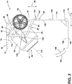
FIG. 2 is a side view of the concrete mixer ofFIG. 1 in the open configuration. -
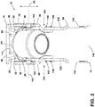
FIG. 3 is a front view of the concrete mixer ofFIG. 1 in the open configuration. -
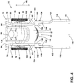
FIG. 4 is a rear view of the concrete mixer ofFIG. 1 in the open configuration. -
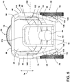
FIG. 5 is a top view of the concrete mixer ofFIG. 1 in the open configuration. -
FIG. 6 is a bottom view of the concrete mixer ofFIG. 1 in the open configuration. -
FIG. 7 is a detailed view of a linkage. -
FIG. 8 is a perspective view of the concrete mixer ofFIG. 1 in a closed configuration. -
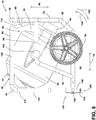
FIG. 9 is a side view of the concrete mixer ofFIG. 1 in the closed configuration. -
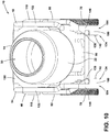
FIG. 10 is a front view of the concrete mixer ofFIG. 1 in the closed configuration. -
FIG. 11 is a rear view of the concrete mixer ofFIG. 1 in the closed configuration. -
FIG. 12 is a top view of the concrete mixer ofFIG. 1 in the closed configuration. -
FIG. 13 is a bottom view of the concrete mixer ofFIG. 1 in the closed configuration. -
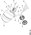
FIG. 14 is a perspective view of a concrete mixer according to another embodiment. -
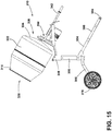
FIG. 15 is a side view of the concrete mixer ofFIG. 14 . -
FIG. 16 is a front view of the concrete mixer ofFIG. 14 . -
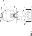
FIG. 17 is a rear view of the concrete mixer ofFIG. 14 . -
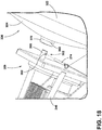
FIG. 18 is a detailed view of a detachable connection ofFIG. 14 . - Before any embodiments of the invention are explained in detail, it is to be understood that the invention is not limited in its application to the details of construction and the arrangement of components set forth in the following description or illustrated in the following drawings. The invention is capable of other embodiments and of being practiced or of being carried out in various ways. Also, it is to be understood that the phraseology and terminology used herein is for the purpose of description and should not be regarded as limiting.
-
FIGS. 1-13 illustrate one embodiment of aconcrete mixer 10. As will be discussed in greater detail below, theconcrete mixer 10 is convertible between an open configuration and a closed configuration.FIGS. 1-6 illustrate theconcrete mixer 10 in an open configuration andFIGS. 8-13 illustrate theconcrete mixer 10 in a closed configuration. - The
concrete mixer 10 includes amixing tub 14 and astand 18. The mixingtub 14 is generally cylindrical in shape and includes anannular side wall 22 extending between aclosed end 26 and anopen end 30. Theclosed end 26 is formed by abottom wall 34. In other embodiments, the mixingtub 14 can be other shapes and sizes suitable to hold concrete. - The
stand 18 includes amain frame 46, asecondary frame 50, andbase frame 54. In the illustrated embodiment, thesecondary frame 50 and thebase frame 54 are movable relative to themain frame 46. In other embodiments, one or both of thesecondary frame 50 and thebase frame 54 are fixed relative to themain frame 46. - The
main frame 46 supports the mixingtub 14. Themain frame 46 includes two generally L-shapedsupports 58 that are positioned on opposite sides of the mixingtub 14. Each L-shapedsupport 58 has afirst arm 62 extending in a first direction 66 (e.g., a vertical direction as shown inFIG. 2 ) and asecond arm 70 extending in a second direction 74 (e.g., a horizontal direction as shown inFIG. 2 ). The L-shapedsupports 58 are oriented such that thefirst arms 62 of each L-shapedsupport 58 are aligned and thesecond arms 70 of each L-shapedsupports 58 are aligned. Additionally, each L-shapedsupport 58 includes awheel 78 rotatably coupled to thefirst arm 62 of the L-shaped support. As will be discussed in greater detail below, thewheels 78 help to transport theconcrete mixer 10 when thestand 18 is in the closed configuration. - The L-shaped
supports 58 are spaced apart from one another and are connected to one another by first and second cross bars 82, 86, respectively. Thefirst cross bar 82 extends between thefirst arms 62 of the L-shapedsupports 58 and thesecond cross bar 86 extends between thesecond arms 70 of the L-shaped supports 58. In addition, abrace 90 extends between thefirst arm 62 and thesecond arm 70 of each L-shaped support. Themain frame 46 supports the mixingtub 14 via thebraces 90. However, in other embodiments, the mixingtub 14 is supported by other parts of themain frame 46. - In the illustrated embodiment, the
secondary frame 50 rotatably couples the mixingtub 14 to themain frame 46. Specifically, thesecondary frame 50 includes ahub 94 coupled to the mixingtub 14, and a pair oflinkages 98 coupled to themain frame 46. Thesecondary frame 50 has a generally U-shaped body that wraps around thebottom wall 34 of the mixingtub 14 and extends along opposite sides of the mixingtub 14. Thehub 94 is coupled to thebottom wall 34 of the mixingtub 14, while thelinkages 98 extend from thehub 94, around the bottom of the mixingtub 14, and at least partially along opposite sides of the mixingtub 14. - The
linkages 98 are rotatably coupled to thebraces 90 on themain frame 46 at adistal end 102 of thelinkages 98. This connection allows the mixingtub 14 to pivot relative to themain frame 46 about afirst axis 106. For example, the mixingtub 14 can be pivoted downward to pour concrete out of the mixingtub 14. Similarly, the mixingtub 14 can also pivot relative to themain frame 46 in order to maintain an upwards position to prevent concrete from spilling when thestand 18 is converted between the open configuration and the closed configuration. In other embodiments, thelinkages 98 can be coupled to other parts of themain frame 46 or may be fixedly coupled to themain frame 46 such that the mixingtub 14 cannot rotate. - In some embodiments, the mixing
tub 14 is also rotatably coupled to thehub 94 such that the mixingtub 14 is capable of spinning about a second axis 110 (FIG. 3 ). In the illustrated embodiment, thesecondary frame 50 also includeshandles 114 extending outwardly from thehub 94. Thehandles 114 enable a user to pivot the mixingtub 14 about thefirst axis 106 to pour the concrete. - The
base frame 54 is rotatably coupled to themain frame 46 via thefirst arms 62 of the L-shaped supports 58. Thebase frame 54 also includes two generally L-shapedsupports 118 that are positioned on opposite sides of the mixingtub 14. Each L-shapedsupport 118 has afirst leg 122 extending in the first direction 66 (e.g., a vertical direction as shown inFIG. 2 ) and asecond leg 126 extending in the second direction 74 (e.g., a horizontal direction as shown inFIG. 2 ). The L-shapedsupports 58 are oriented such that thefirst legs 122 of each L-shapedsupport 118 are aligned and thesecond legs 126 of each L-shapedsupport 118 are aligned. The L-shapedsupports 118 of thebase frame 54 are spaced apart from one another and are connected to one another by athird cross bar 130. Thethird cross bar 130 extends between thesecond legs 126 of the L-shapedsupports 118. Each L-shapedsupport 118 of thebase frame 54 corresponds to an L-shapedsupport 58 of themain frame 46. - The
base frame 54 is connected to themain frame 46 byhinges 134 that rotatably couple L-shapedsupports 118 of thebase frame 54 to corresponding L-shapedsupports 58 of themain frame 46. Eachhinge 134 connects thefirst arm 62 to thefirst leg 122 of corresponding L-shapedsupports hinge 134 includes apivot member 138, a lockingmember 142, and abracket 146. In the illustrated embodiment, thepivot member 138 is a shaft extending through thefirst arm 62 and thefirst leg 122 of each pair of corresponding L-shapedsupports pivot member 138 allows thefirst leg 122 to pivot relative to thefirst arm 62, which therefore, enables theentire base frame 54 to pivot relative to themain frame 46. - In the illustrated embodiment, the locking
member 142 is a locking pin that extends through thefirst arm 62 and thefirst leg 122 of each pair of corresponding L-shapedsupports member 142 can be selectively removed from thestand 18. When the lockingmember 142 is inserted through thefirst arm 62 and thefirst leg 122, thebase frame 54 and themain frame 46 are rotatably fixed. When the lockingmember 142 is removed from thefirst arm 62 andfirst leg 122, thebase frame 54 and themain frame 46 are rotatable relative to one another. - In the illustrated embodiment, the
bracket 146 functions as arotation limiter 150 when thestand 18 is in the open configuration and functions as asupport foot 154 when thestand 18 is in the closed configuration. As shown inFIG. 7 , thebracket 146 is capable of limiting the degree of rotation of thebase frame 54 relative to themain frame 46. Thebracket 146 is coupled to and rotates with thefirst leg 122. Thebracket 146 includes arotation limiter 150 that extends across both thefirst arm 62 and thefirst leg 122 in order to stop rotation of thefirst leg 122 relative to thefirst arm 62. Additionally, as shown inFIG. 9 , thebracket 146 functions as afoot 154 to support theconcrete mixer 10. Specifically, thebrackets 146 and thewheels 78 engage a ground surface to support theconcrete mixer 10 when in the closed configuration. - The
concrete mixer 10 can convert between an open configuration and a closed configuration by rotating thebase frame 54 relative to themain frame 46. When in the open configuration (FIGS. 1-6 ), thebase frame 54 is rotated in firstrotational direction 158 relative to the main frame 46 (e.g., counterclockwise inFIGS. 2 and9 ). When in the open configuration themain frame 46 and thebase frame 54 form a C-shape when viewed from the side, as shown inFIG. 2 . In this configuration, the correspondingfirst arms 62 and thefirst legs 122 are oriented parallel to one another. Thesecond legs 126 and thethird cross bar 130 engage a ground surface to support themain frame 46 above the ground. Thesecond arms 70 support the mixingtub 14 above a pouring location, such as the ground or a wheel barrow, as shown inFIG. 1 . In other words, thefirst arms 62 andfirst legs 122 extend in thefirst direction 66, while thesecond arms 70 andsecond legs 126 extend in thesecond direction 74. The open configuration is often used during operation in order to pour the concrete. - When in the closed configuration (
FIGS. 8-13 ), thebase frame 54 is rotated in a second rotational direction 162 (e.g., clockwise inFIGS. 2 and9 ). When in the closed configuration, themain frame 46 and thebase frame 54 form a square shape. In this configuration, thefirst arms 62 andfirst legs 122 are oriented perpendicular to one another. Thesecond arms 70 and thefirst legs 122 extend in thesecond direction 66, while thefirst arms 62 and thesecond legs 126 extend in thefirst direction 74. Thefirst arms 62 are positioned generally parallel to the ground surface in order to enable thewheels 78 to engage the ground surface. In addition, thebrackets 146 engage the ground and function as support feet, which cooperate with thewheels 78 to support theconcrete mixer 10. - When the
brackets 146 engage the ground surface, thebrackets 146 prevent theconcrete mixer 10 from unintentionally rolling away. To transport theconcrete mixer 10, thestand 18 can be pivoted such that thebrackets 146 disengage the ground and theconcrete mixer 10 is supported by only thewheels 78. Thewheels 78 can then be used to help transport theconcrete mixer 10. Thesecond cross bar 86 can be grasped by a user to help tip theconcrete mixer 10 onto thewheels 78. The closed configuration is often used to transport theconcrete mixer 10. However, the closed configuration can also be used during operation to pour the concrete. When in the closed configuration, the mixingtub 14 is supported at a lower height above the ground surface (i.e., relative to a support surface) than when in the open configuration. Accordingly, the open configuration and closed configuration can also be used to support the mixingtub 14 at different heights above the ground surface. -
FIGS. 14-18 illustrate another embodiment of aconcrete mixer 310. Theconcrete mixer 310 includes a mixingtub 314 and astand 318. The mixingtub 314 is generally cylindrical in shape and includes anannular side wall 322 extending between aclosed end 326 and anopen end 330. Theclosed end 326 is formed by abottom wall 334. In other embodiments, the mixingtub 314 can be other shapes and sizes suitable to hold concrete. - The
stand 318 includes amain frame 346 and abase frame 354. Themain frame 346 includes acolumn 338 that supports the mixingtub 314 at different heights relative to the ground surface (i.e., relative to a support surface). In some embodiments, thecolumn 338 is atelescoping column 338 that is capable of extending between at least a first length and a second length. Themain frame 346 also includes a pair ofhandles 342 extending outwardly from thecolumn 338 to allow a user to maneuver and control theconcrete mixer 310. - With reference to
FIG. 18 , the mixingtub 314 is removably coupled to themain frame 346 bydetachable connection 358. In the illustrated embodiment, theconcrete mixing tub 314 is removably attached to thestand 318 by a lockingpin connection 362. The lockingpin connection 362 includes amale part 366 extending from themain frame 346, which is inserted into afemale part 370 extending from thebottom wall 334 of the mixingtub 314. In other embodiments, themale part 366 may extend from thebottom wall 334 of the mixingtub 314 and the female part may extend from themain frame 346. Once themale part 366 and thefemale part 370 are engaged, alocking pin 374 extends transversely throughholes 382 in both the male andfemale parts tub 314 to themain frame 346. The mixingtub 314 can be detached from thestand 318 by removing thelocking pin 374 and disengaging themale part 366 from thefemale part 370. - The
base frame 354 includes atransport leg 386 and astationary leg 390. Thetransport leg 386 and thestationary leg 390 extend outwardly from thecolumn 338 and away from one another. Thetransport leg 386 has a triangular shape and includes a set ofwheels 378 to help transport theconcrete mixer 310. Thestationary leg 390 has a triangular shape and includes afoot 394 to prevent theconcrete mixer 310 from rolling away when theconcrete mixer 310 is not being transported. In the illustrated embodiment, thefoot 394 is formed by an elongated tubular member, however, in other embodiments, thefoot 394 can be other shapes and sizes. To transport theconcrete mixer 310, a user can pull upward on thehandles 342 to lift thefoot 394. Once thefoot 394 is disengaged from the ground surface the user can tilt thestand 318 towards thetransport leg 386 to transfer the weight of theconcrete mixer 310 over thewheels 378 and begin to roll theconcrete mixer 310 to the work location. Once the work location is reached, thefoot 394 can be lowered to engage the ground and prevent unwanted movement of theconcrete mixer 310. In the illustrated embodiment, thefoot 394 extends in a direction perpendicular to the direction of travel to further prevent unwanted movement of theconcrete mixer 310. - The concrete mixers disclosed herein provide a user with adjustability to position the mixing tub in different orientations and heights. The concrete mixers also provide a user with mobility to transport the concrete easily and efficiently. Additionally, the mixing tub can be removed entirely from the stand through a simple detachment mechanism, which does not require additional tools.
- Various features and advantages of the invention are set forth in the following claims.
Claims (15)
- A concrete mixer, comprising:a mixing tub including an annular side wall and a bottom wall;a main frame configured to rotatably support the mixing tub, the main frame including a telescoping member that is capable of extending between a first length and a second length; anda base frame supporting the main frame, the base frame including a first leg having a first wheel to enable transport of the concrete mixer, and a second leg having a foot to prevent the concrete mixer from rolling away.
- The concrete mixer of claim 1, wherein the main frame further includes a handle.
- The concrete mixer of claim 1, wherein the mixing tub is coupled to the main frame by a detachable connection for removably coupling the mixing tub to the main frame.
- The concrete mixer of claim 3, wherein the detachable connection includes a male part and a female part for receiving the male part, wherein the male part is located on one of the main frame and the bottom wall of the mixing tub and the female part is located on the other one of the main frame and the bottom wall of the mixing tub, and, optionally,
the detachable connection further includes a locking pin, the locking pin being removably engagable with the male part and the female part. - The concrete mixer of any one of claims 1 to 4,
wherein the first leg has a triangular shape and includes a second wheel;
and/or
wherein the first leg and the second leg each extend outwardly from the main frame in opposing directions;
and/or
wherein the foot is formed by an elongated tubular member. - A concrete mixer, comprising:a mixing tub including an annular side wall and a bottom wall;a main frame configured to rotatably support the mixing tub; anda base frame coupled to the main frame, wherein the base frame is movable relative to the main frame between an open configuration corresponding to a first height of the mixing tub relative to a support surface and a closed configuration corresponding to a second height of the mixing tub relative to a support surface.
- The concrete mixer of claim 6, wherein the main frame and the base frame form a C-shape when in the open configuration.
- The concrete mixer of claim 6 or 7, wherein the main frame and the base frame form a square shape when in the closed configuration.
- The concrete mixer of any one of claims 6 to 8, wherein the main frame includes two L-shaped supports each formed by a first arm and a second arm, and wherein the base frame includes two L-shaped supports each formed by a first leg and a second leg.
- The concrete mixer of claim 9, wherein the first arms and the first legs are oriented generally parallel to one another when in the open configuration, and wherein the first arms and the first legs are oriented generally perpendicular to one another when in the closed configuration.
- The concrete mixer of any one of claims 6 to 10, further comprising a secondary frame rotatably coupling the mixing tub to the main frame, and, optionally,
the secondary frame includes a handle to help rotate the mixing tub relative to the main frame. - The concrete mixer of any one of claims 6 to 11, wherein the base frame includes a locking member to selectively prevent movement of the base frame relative to the main frame.
- The concrete mixer of any one of claims 6 to 12, further including wheels coupled to the main frame to assist in transport of the concrete mixer.
- The concrete mixer of any one of claims 6 to 13, further including a bracket coupled to the base frame, the bracket configured to limited rotation of the base frame relative to the main frame, and, optionally,
the bracket is configured to engage the ground to prevent the concrete mixer from unintentionally rolling when the concrete mixer is in the closed configuration. - A concrete mixer, comprising:a mixing tub including an annular side wall and a bottom wall;a main frame configured to rotatably support the mixing tub; anda base frame supporting the main frame;wherein at least one of the main frame and the base frame is adjustable to move the mixing tub from a first height relative to a support surface to a second height relative to a support surface.
Applications Claiming Priority (1)
| Application Number | Priority Date | Filing Date | Title |
|---|---|---|---|
| US201762608851P | 2017-12-21 | 2017-12-21 |
Publications (2)
| Publication Number | Publication Date |
|---|---|
| EP3536469A2 true EP3536469A2 (en) | 2019-09-11 |
| EP3536469A3 EP3536469A3 (en) | 2020-01-15 |
Family
ID=64870346
Family Applications (1)
| Application Number | Title | Priority Date | Filing Date |
|---|---|---|---|
| EP18214824.7A Withdrawn EP3536469A3 (en) | 2017-12-21 | 2018-12-20 | Concrete mixer stand |
Country Status (5)
| Country | Link |
|---|---|
| US (1) | US20190193299A1 (en) |
| EP (1) | EP3536469A3 (en) |
| CN (1) | CN210082082U (en) |
| CA (1) | CA3028061A1 (en) |
| MX (1) | MX2019000237A (en) |
Cited By (3)
| Publication number | Priority date | Publication date | Assignee | Title |
|---|---|---|---|---|
| CN110666964A (en) * | 2019-10-11 | 2020-01-10 | 长乐智睿恒创节能科技有限责任公司 | Concrete mixing equipment is used in hydraulic engineering construction |
| CN112060330A (en) * | 2020-09-16 | 2020-12-11 | 马鞍山司匹诺机械科技有限公司 | Cement production mixing device and use method thereof |
| CN114259901A (en) * | 2021-11-30 | 2022-04-01 | 镇江华瑞伪装防护技术有限公司 | Camouflage paint transportation trolley with stirring function and use method thereof |
Families Citing this family (4)
| Publication number | Priority date | Publication date | Assignee | Title |
|---|---|---|---|---|
| CN110228133B (en) * | 2019-07-18 | 2024-08-09 | 中交路桥建设有限公司 | Prefabricated part form removing device and construction method thereof |
| CN111422228A (en) * | 2020-04-10 | 2020-07-17 | 刘恩春 | Chinese-medicinal material transport vechicle and mechanism is beaten to chinese-medicinal material hammer thereof |
| CN114590305B (en) * | 2022-03-19 | 2024-01-02 | 河南宏钦建设工程有限公司 | Material conveying device |
| CN115045260B (en) * | 2022-06-29 | 2024-07-23 | 中建三局集团有限公司 | A mixing backfilling method for solidified soil |
Family Cites Families (10)
| Publication number | Priority date | Publication date | Assignee | Title |
|---|---|---|---|---|
| US2664276A (en) * | 1951-02-16 | 1953-12-29 | Wagner Iron Works | Concrete mixer with lifting and tilting mechanism |
| US2706623A (en) * | 1952-06-11 | 1955-04-19 | Fred J Styes | Concrete mixing, carrying and pouring attachment for a tractor |
| US3317194A (en) * | 1966-06-23 | 1967-05-02 | Robert E Heltzel | Concrete mixer |
| GB1223417A (en) * | 1967-06-01 | 1971-02-24 | William Thomas Teagle | Improvements in and relating to portable mixing machines |
| AU542065B2 (en) * | 1980-04-09 | 1985-02-07 | Isaacson, N.D. | Concrete mixer mounting on front end loader |
| GB2093410B (en) * | 1981-01-17 | 1984-04-18 | York Forge & Welding Co Ltd | Mixers for concrete and other materials |
| AU2041683A (en) * | 1982-10-19 | 1984-05-03 | Lightburn & Co. Ltd. | Concrete mixer with raisable bowl |
| US5474379A (en) * | 1995-03-31 | 1995-12-12 | Perry; L. F. | Portable high volume cement mixer |
| CN201012522Y (en) * | 2007-03-21 | 2008-01-30 | 任哲珠 | Multifunctional miniature stirring machine |
| MX2015008420A (en) * | 2012-12-28 | 2016-02-18 | Ryon Brown | A mobile cart convertible among a plurality of operational modes. |
-
2018
- 2018-12-18 US US16/224,348 patent/US20190193299A1/en not_active Abandoned
- 2018-12-19 CA CA3028061A patent/CA3028061A1/en not_active Abandoned
- 2018-12-20 CN CN201822149746.5U patent/CN210082082U/en not_active Expired - Fee Related
- 2018-12-20 EP EP18214824.7A patent/EP3536469A3/en not_active Withdrawn
-
2019
- 2019-01-07 MX MX2019000237A patent/MX2019000237A/en unknown
Non-Patent Citations (1)
| Title |
|---|
| None |
Cited By (3)
| Publication number | Priority date | Publication date | Assignee | Title |
|---|---|---|---|---|
| CN110666964A (en) * | 2019-10-11 | 2020-01-10 | 长乐智睿恒创节能科技有限责任公司 | Concrete mixing equipment is used in hydraulic engineering construction |
| CN112060330A (en) * | 2020-09-16 | 2020-12-11 | 马鞍山司匹诺机械科技有限公司 | Cement production mixing device and use method thereof |
| CN114259901A (en) * | 2021-11-30 | 2022-04-01 | 镇江华瑞伪装防护技术有限公司 | Camouflage paint transportation trolley with stirring function and use method thereof |
Also Published As
| Publication number | Publication date |
|---|---|
| CN210082082U (en) | 2020-02-18 |
| EP3536469A3 (en) | 2020-01-15 |
| CA3028061A1 (en) | 2019-06-21 |
| MX2019000237A (en) | 2019-09-04 |
| US20190193299A1 (en) | 2019-06-27 |
Similar Documents
| Publication | Publication Date | Title |
|---|---|---|
| US20190193299A1 (en) | Concrete mixer stand | |
| US10485724B2 (en) | Rollator-trolley with adjustable handle position depending on use | |
| US7066866B1 (en) | Chin up bar assembly with sliding and swiveling handles | |
| US20120091674A1 (en) | Self-balancing multifunctional wheelbarrow | |
| US2914336A (en) | Collapsible golf bag cart | |
| JP2012505806A (en) | Lifting vehicle | |
| US9204587B2 (en) | Manual shovel accessory and shovel apparatus with rear end fulcrum and front and rear upright handles | |
| US11931303B1 (en) | Foldable tiltable wheelchair and frame therefor | |
| US6446989B1 (en) | Pin drive wheelbarrow | |
| US3893687A (en) | Hand truck with safety stand | |
| US2800336A (en) | Hand truck | |
| KR20150085879A (en) | Safety Ladders | |
| WO2005060784A1 (en) | Fold-out wheeled support for long wheeled travel case | |
| US20160288478A1 (en) | Apparatus for removal of flooring | |
| WO2005073048A1 (en) | Foldable wheelbarrow and hand cart | |
| US7011485B2 (en) | Tiltable hand truck | |
| JP2010100185A (en) | Operation handle in simplified spraying vehicle | |
| EP1747136A1 (en) | Transportation cart primarily for use in an animal barn | |
| US20120187272A1 (en) | Wheeled Collapsible Stand for a Power Driven Machine | |
| JPS62117557A (en) | Moving truck | |
| US1128856A (en) | Spraying-machine. | |
| EP2559412B1 (en) | Appareil de levage de personnes avec fonctions supplémentaires | |
| US20220315085A1 (en) | Portable load lift device | |
| CN214775951U (en) | A rollover-proof construction trolley | |
| JP5087125B2 (en) | Care shifter |
Legal Events
| Date | Code | Title | Description |
|---|---|---|---|
| PUAI | Public reference made under article 153(3) epc to a published international application that has entered the european phase |
Free format text: ORIGINAL CODE: 0009012 |
|
| STAA | Information on the status of an ep patent application or granted ep patent |
Free format text: STATUS: THE APPLICATION HAS BEEN PUBLISHED |
|
| AK | Designated contracting states |
Kind code of ref document: A2 Designated state(s): AL AT BE BG CH CY CZ DE DK EE ES FI FR GB GR HR HU IE IS IT LI LT LU LV MC MK MT NL NO PL PT RO RS SE SI SK SM TR |
|
| AX | Request for extension of the european patent |
Extension state: BA ME |
|
| PUAL | Search report despatched |
Free format text: ORIGINAL CODE: 0009013 |
|
| RIC1 | Information provided on ipc code assigned before grant |
Ipc: B62B 1/20 20060101ALI20191205BHEP Ipc: F16M 11/28 20060101ALI20191205BHEP Ipc: B28C 5/18 20060101AFI20191205BHEP Ipc: B28C 5/08 20060101ALI20191205BHEP Ipc: B01F 15/00 20060101ALI20191205BHEP Ipc: B62B 1/18 20060101ALI20191205BHEP |
|
| AK | Designated contracting states |
Kind code of ref document: A3 Designated state(s): AL AT BE BG CH CY CZ DE DK EE ES FI FR GB GR HR HU IE IS IT LI LT LU LV MC MK MT NL NO PL PT RO RS SE SI SK SM TR |
|
| AX | Request for extension of the european patent |
Extension state: BA ME |
|
| RIC1 | Information provided on ipc code assigned before grant |
Ipc: B01F 15/00 20060101ALI20191210BHEP Ipc: F16M 11/28 20060101ALI20191210BHEP Ipc: B62B 1/20 20060101ALI20191210BHEP Ipc: B28C 5/08 20060101ALI20191210BHEP Ipc: B62B 1/18 20060101ALI20191210BHEP Ipc: B28C 5/18 20060101AFI20191210BHEP |
|
| STAA | Information on the status of an ep patent application or granted ep patent |
Free format text: STATUS: REQUEST FOR EXAMINATION WAS MADE |
|
| 17P | Request for examination filed |
Effective date: 20200220 |
|
| RBV | Designated contracting states (corrected) |
Designated state(s): AL AT BE BG CH CY CZ DE DK EE ES FI FR GB GR HR HU IE IS IT LI LT LU LV MC MK MT NL NO PL PT RO RS SE SI SK SM TR |
|
| RAP1 | Party data changed (applicant data changed or rights of an application transferred) |
Owner name: TTI (MACAO COMMERCIAL OFFSHORE) LIMITED |
|
| STAA | Information on the status of an ep patent application or granted ep patent |
Free format text: STATUS: EXAMINATION IS IN PROGRESS |
|
| 17Q | First examination report despatched |
Effective date: 20210422 |
|
| RAP1 | Party data changed (applicant data changed or rights of an application transferred) |
Owner name: TECHTRONIC CORDLESS GP |
|
| REG | Reference to a national code |
Ref country code: DE Ref legal event code: R079 Free format text: PREVIOUS MAIN CLASS: B28C0005180000 Ipc: B28C0005080000 |
|
| GRAP | Despatch of communication of intention to grant a patent |
Free format text: ORIGINAL CODE: EPIDOSNIGR1 |
|
| RIC1 | Information provided on ipc code assigned before grant |
Ipc: B62B 1/26 20060101ALI20221129BHEP Ipc: B62B 1/22 20060101ALI20221129BHEP Ipc: B62B 1/20 20060101ALI20221129BHEP Ipc: B01F 35/43 20220101ALI20221129BHEP Ipc: B28C 5/18 20060101ALI20221129BHEP Ipc: B28C 5/08 20060101AFI20221129BHEP |
|
| STAA | Information on the status of an ep patent application or granted ep patent |
Free format text: STATUS: GRANT OF PATENT IS INTENDED |
|
| INTG | Intention to grant announced |
Effective date: 20230105 |
|
| STAA | Information on the status of an ep patent application or granted ep patent |
Free format text: STATUS: THE APPLICATION IS DEEMED TO BE WITHDRAWN |
|
| 18D | Application deemed to be withdrawn |
Effective date: 20230516 |