EP3536391A1 - Filter - Google Patents
Filter Download PDFInfo
- Publication number
- EP3536391A1 EP3536391A1 EP19157905.1A EP19157905A EP3536391A1 EP 3536391 A1 EP3536391 A1 EP 3536391A1 EP 19157905 A EP19157905 A EP 19157905A EP 3536391 A1 EP3536391 A1 EP 3536391A1
- Authority
- EP
- European Patent Office
- Prior art keywords
- filter
- folds
- support housing
- end cap
- pack
- Prior art date
- Legal status (The legal status is an assumption and is not a legal conclusion. Google has not performed a legal analysis and makes no representation as to the accuracy of the status listed.)
- Granted
Links
Images

Classifications
-
- B—PERFORMING OPERATIONS; TRANSPORTING
- B01—PHYSICAL OR CHEMICAL PROCESSES OR APPARATUS IN GENERAL
- B01D—SEPARATION
- B01D35/00—Filtering devices having features not specifically covered by groups B01D24/00 - B01D33/00, or for applications not specifically covered by groups B01D24/00 - B01D33/00; Auxiliary devices for filtration; Filter housing constructions
- B01D35/02—Filters adapted for location in special places, e.g. pipe-lines, pumps, stop-cocks
- B01D35/027—Filters adapted for location in special places, e.g. pipe-lines, pumps, stop-cocks rigidly mounted in or on tanks or reservoirs
- B01D35/0273—Filtering elements with a horizontal or inclined rotation or symmetry axis submerged in tanks or reservoirs
-
- B—PERFORMING OPERATIONS; TRANSPORTING
- B01—PHYSICAL OR CHEMICAL PROCESSES OR APPARATUS IN GENERAL
- B01D—SEPARATION
- B01D29/00—Filters with filtering elements stationary during filtration, e.g. pressure or suction filters, not covered by groups B01D24/00 - B01D27/00; Filtering elements therefor
- B01D29/01—Filters with filtering elements stationary during filtration, e.g. pressure or suction filters, not covered by groups B01D24/00 - B01D27/00; Filtering elements therefor with flat filtering elements
- B01D29/05—Filters with filtering elements stationary during filtration, e.g. pressure or suction filters, not covered by groups B01D24/00 - B01D27/00; Filtering elements therefor with flat filtering elements supported
- B01D29/07—Filters with filtering elements stationary during filtration, e.g. pressure or suction filters, not covered by groups B01D24/00 - B01D27/00; Filtering elements therefor with flat filtering elements supported with corrugated, folded or wound filtering sheets
-
- B—PERFORMING OPERATIONS; TRANSPORTING
- B01—PHYSICAL OR CHEMICAL PROCESSES OR APPARATUS IN GENERAL
- B01D—SEPARATION
- B01D2201/00—Details relating to filtering apparatus
- B01D2201/04—Supports for the filtering elements
- B01D2201/0415—Details of supporting structures
- B01D2201/0423—Details of supporting structures not in the inner side of the cylindrical filtering elements
-
- B—PERFORMING OPERATIONS; TRANSPORTING
- B01—PHYSICAL OR CHEMICAL PROCESSES OR APPARATUS IN GENERAL
- B01D—SEPARATION
- B01D2201/00—Details relating to filtering apparatus
- B01D2201/29—Filter cartridge constructions
- B01D2201/291—End caps
Definitions
- the invention relates to a filter, in particular transmission oil filter, and a filter device for receiving such a filter.
- a filter device for the transmission oil cf. DE 10 2007 023 641 B4 in which a filter device for transmission oil is disclosed, which operates as a suction filter.
- the design as a suction filter is characterized by a much lower need for installation space compared to a pressure oil filter device, so that they, unlike pressure oil filter devices, which usually works in a side stream and are mounted externally within the gear housing or on the gear housing without difficulty directly into the Oil sump oil pan of the relevant transmission can be installed.
- the invention has the object to provide a filter that is characterized both by a particularly compact design and by a particularly large compared to the size effective filter surface.
- the invention provides for solving this problem in front of a received in an at least partially fluid-permeable support housing filter pack whose filter material is placed in folds of the same height and length.
- a filter package formed from such a folding arrangement a particularly large effective filter area can be realized in comparison to the overall dimension of the filter.
- the arrangement can be made such that the support housing comprises the filter pack and that the folds of the filter pack with their two opposite, free end faces in each case in abutment with a length of the folds predetermining, closed end cap of the support housing.
- the individual filter pleats of the filter pack on a arrival and a downstream side, which correspond to the unfiltrate or filtrate side, wherein the inflow side of all filter pleats to a central supply point for fluid is connected, which is part of a foot-side end cap of the support housing.
- the arrangement may be such that the support housing with its fluid-permeable jacket part, consisting essentially of longitudinal and transverse struts, extends arcuately between its two end caps and the end cap.
- the shell part with its struts, as well as end caps and end cap can be made with advantage of a plastic material, such as PA6, as an injection molded part.
- the longitudinal struts of the shell part can extend parallel to the filter pleats between the two end caps, while the transverse struts are arranged to extend transversely thereto.
- the support housing can serve to form a kind of protective hood of the at least partial outer support of the filter material with its filter folds.
- the two free longitudinal sides of the two outermost folds which limit the folded filter material in the longitudinal direction parallel to the filter folds, can advantageously be wrapped around a respective longitudinal edge of the end cap and fixed on this longitudinal edge to form a fixed strip.
- the locating strips thereby form, in cooperation with the closed end caps of the support housing, the separation between the supply point on the end cap and the outside of the filter pack and thus the separation between the unfiltrate side and the outer filtrate side on the filter pack.
- the respective fixing strip is received at its respective free end on an adjacent end cap of the support housing.
- the filter pack has 5 to 25, preferably 8 to 20, pleated filter pleats in a zig-zag arrangement, which are accommodated in the support housing.
- the filter material may be two or more layers and be formed by its filter fineness as a coarse filter, which is guaranteed by a wire or plastic mesh, which at least partially covers the filter sides, their inherent stability.
- the invention is according to claim 11 and a filter device for receiving a filter according to one of the claims 1 to 10, which is interchangeable housed in a filter housing having a suction port on the downstream side of the filter and a supply port on the non-filtrate side of the filter.
- the supply connection of the filter housing form a connection piece, on which a supply connection of the supply point of the filter can be pushed.
- the filter medium to be flowed through by the transmission oil of the filter according to the invention is formed by a filter pack 2, which has the shape of a cube on the whole.
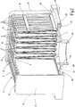
- the package 2 is formed of a filter material 4 in the form of a flat web which is laid in folds. As the figures show, the fold is formed so that uniform folds 6 are formed, which have the same height (measured in the vertical direction of the figures) and the same length (measured perpendicular to the plane of the drawing Fig. 1 ). In the illustrated embodiment, nine nine folds 6 are provided to form the filter pack.
- the filter material 4 consists, as is usual with folded or pleated filter materials, of several layers, wherein a wire mesh or plastic mesh, which at least partially comprises the folds 6, a kind of mesh-pack is formed, which gives the folds 6 an inherent stability.
- the filter package 2 thus formed is designed as a coarse filter, with a filter fineness in the range of 50 to 100 ⁇ m.
- a support housing 8 and two end caps 10 are provided as outer casing for the filter pack 2.
- the latter are the same design and have a flat, closed top surface 12 (s. Fig. 2 ), which limit the axial length of the folds 6, which abut with their free end faces on the cover plates 12.
- the support housing 8 has the form of a fluid-permeable jacket, which forms a partially outer support of the filter pack 2 in the manner of a protective hood.
- the shell is formed like a cage from two groups of struts, of which, as most clearly the Fig.
- longitudinal struts 14 group at a small distance from each other in arcuate course along the two vertical side edges and the horizontal upper side edge of the end caps 10 extends.
- a second group are provided as a connector of the longitudinal struts 14 to these perpendicular transverse struts 16, which are arranged at a greater distance from each other than the longitudinal struts 14, and extend over the entire series of longitudinal struts 14 from cover plate 12 to cover plate 12 of the end caps 10.
- Die both front ends of the formed from the struts 14, 16 shell of the support housing 8 are overlapped by an angled bordering wheel 18 of the end caps 10 (s. Fig. 2 ).
- the foot-side termination of the filter pack 2 is formed by an end cap 20, which merges from a horizontal, outer longitudinal edge 22 via a funnel-like bottom portion 24 into an opening 26 which forms the supply point for the inflow of unfiltered material to the inside of the filter pack 2.
- outer Filtratseite the two free longitudinal sides 28 are extended at the two outermost folds 6 so that they can be placed around the associated longitudinal edge 22 of the end cap 20 and below Formation of a Festlegestsammlungs are definable.
- Fig. 2 shows the edging edges 18 of the end caps 10 with a laterally projecting end portion 30 a the longitudinal sides 28 of the last folds 6 comprehensive recording for the formed on the longitudinal edge 22 of the end cap 20 FestlegestLite.
- the Fig. 1 shows by way of example the filter device according to the invention receiving the filter.
- the filter device has a filter housing 34, which is formed in two parts with a suction connection 36 having an upper housing part 38 and a bottom part 40 which are detachably connected to one another at a connection point 42.
- the upper part 38 has, like the filter pack 2 with the support housing 8, on the whole the shape of a cube, the support housing. 8 forming a lateral clearance 44 forming the filtrate side communicating with the suction port 36.
- the bottom part 40 has the shape of a shallow trough with a centrally located, inwardly projecting connecting piece 46, in which a supply pipe 48 can be inserted, which forms the supply point as an inlet for the unfiltered at the opening 26 of the end cap 20.
- An annular groove 50 formed on the connection piece 46 forms the seat for a sealing element forming the seal on the connection piece 46, 48.
- the support housing 8 surrounding the filter pack 2 as well as the end caps 10 and the end plate 20 may be formed as injection-molded parts of a plastic material such as PA6, wherein the connections between these components may be formed by gluing or welding.
- receiving filter device may also be provided depending on the particular application, a plastic material or optionally a metallic material.
- a pleated flat filter realized with two end caps 10 and an integrated intake in the foot end cap 20.
- the flat filter according to the invention in cube shape is extremely small in terms of its high filter performance and is so far for the tight installation conditions, as they by way of example present in dual-clutch transmissions, particularly suitable.
- the first and last fold of the filter fold arrangement can best be connected to the end cap 20 by means of ultrasonic welding methods.
- the free longitudinal sides 28 of the two outermost folds 6 can also hang from above on the respective longitudinal edge 22 of the end cap 20, then firmly connected by means of said ultrasonic welding process with the associated longitudinal edge 22 to become.
- the two end caps 10 on the bottom or bottom box-shaped bulges which limit a corresponding channel cross-section for the recording.
- the rectangular-shaped end caps 10 can be connected at their adjacent end faces in each case with the filter fold ends (open mesh-pack ends), for example in the context of a welding process, such as a laser transmission welding process, as exemplified in DE 10 2007 013 178 A1 is shown.
- a welding process such as a laser transmission welding process
- an adhesive bonding process may also occur, for example using one- or two-component adhesives.
- the supply port 48 which is integrated into the filter element or filter pack 2, thus stands with its free flow opening transverse to the individual filter folds 6.
- the fluid or oil flow thus meets so far directly on the filter pack 2 without further deflection.
- the cap 20 is tapered in the direction of the supply connection 48, which favors a homogenization of the fluid flow.
- a supporting geometry may be arranged, for example in the form of supporting webs which intervene between the distances of the individual filter folds 6 in order dergestalt in the frame To stabilize flow.
- the support geometry (not shown) can either be glued into the adhesive bed for the filter folds 6 of an end cap 10 and / or be welded together with the filter folds 6 of the filter pack 2 to the remaining other end cap 10.
- wrinkle heights of the pleats 6 can be realized from 6mm to 70mm.
- the required for a meaningful flow gap spacing between adjacent filter pleats 6 can be realized by drainage layers both on the arrival and on the downstream side, so that the fluid or oil flow with as little suction pressure loss through the filter pack 2 can flow.
- the flow of oil on the input side of the filter pack 2 can be distributed over such a large area that each filter fold 6 is flowed through uniformly from bottom to top and with equal volumes ,
- Each individual filter fold 6 is conically widened to the end cap 20 and so far forms a conically upwardly tapered inflow space. After flowing through the individual filter fold 6 from the inside to the outside, starting from this Anströmraum, then passes the filtered fluid on the downstream side with a discharge space between two adjacent folds 6, which widens conically towards the support housing 8 upwards.
- the filter pack 2 can also be formed from individual, superimposed filter webs (not shown) for the filter folds 6, with different filter finenesses, so that a parallel connection of coarse and fine filter material and / or superfine filter material results.
- the flat, pleated suction filter according to the invention is in any case an optional filter concept for cylindrical or oval filter elements and can easily replace them under certain installation space conditions.
- a parallel circuit of coarse and fine filter in a filter pack 2 is possible, the bulk of the volume flow should be coarse filtered and a residual volume flow is finely filtered and ensures over the operating time for a very good Purity level in the range of nearly 100% finely filtered fluid or oil.
- the volumetric flow ratio between coarse and fine filter fraction depends on the selected filter surfaces and the filter fineness ratios. Particularly low differential pressures are achieved in filter operation by the coaxial arrangement of the structures 46, 48 with the nozzle 36 of the suction port in the filter housing 34 based on their common center axis.
Landscapes
- Chemical & Material Sciences (AREA)
- Chemical Kinetics & Catalysis (AREA)
- General Details Of Gearings (AREA)
- Filtration Of Liquid (AREA)
Abstract
Description
- Die Erfindung betrifft ein Filter, insbesondere Getriebeölfilter, sowie eine Filtervorrichtung zur Aufnahme eines solchen Filters.
- Um über lange Betriebszeiträume hinweg einen sicheren und störungsfreien Betrieb von Getrieben sicherzustellen, ist es Stand der Technik, für das Getriebeöl eine Filtervorrichtung vorzusehen, vergleiche
DE 10 2007 023 641 B4 , in der eine Filtervorrichtung für Getriebeöl offenbart ist, die als Saugfilter arbeitet. Die Auslegung als Saugfilter zeichnet sich im Vergleich zu einer Druckölfiltervorrichtung durch einen wesentlich geringeren Bedarf an Einbauraum aus, so dass sie, anders als Druckölfiltervorrichtungen, die üblicherweise in einem Nebenstrom arbeitet und innerhalb des Getriebegehäuses oder am Getriebegehäuse außen angebracht sind, ohne Schwierigkeiten unmittelbar in den Ölsumpf der Ölwanne des betreffenden Getriebes einbaubar sind. - Bei der erwähnten Lösung des Standes der Technik sind in dem Bestreben, eine geringe Bauhöhe zu realisieren, die einen Einbau in den sehr begrenzten, in einem Getriebegehäuse zur Verfügung stehenden Freiraum ermöglicht, als Filterelemente zwei flache Bahnen aus einem Filtervlies vorgesehen. Diese Bahnen sind in Vertikalrichtung, d.h. in Richtung des vom Boden des Getriebegehäuses her einströmenden Saugstromes, zueinander versetzt, wobei die Bahnen durch zwischen ihnen befindliche Abstandhalter in vertikalem Abstand voneinander gehalten sind. Zwar lässt sich dadurch eine verhältnismäßig geringe Bauhöhe realisieren, jedoch steht mit den flachen Bahnen aus Filtervlies nur eine geringe wirksame Filterfläche zur Verfügung, so dass die Effizienz der Abreinigung sich als zumindest für bestimmte Anwendungen als unzureichend erweisen mag.
- Ausgehend von diesem Stand der Technik stellt sich die Erfindung die Aufgabe, ein Filter zur Verfügung zu stellen, das sich sowohl durch eine besonders kompakte Bauweise als auch durch eine im Vergleich zur Baugröße besonders große wirksame Filterfläche auszeichnet.
- Erfindungsgemäß ist diese Aufgabe durch ein Filter mit den im Patentanspruch 1 angegebenen Merkmalen gelöst.
- Demgemäß sieht die Erfindung zur Lösung dieser Aufgabe ein in einem zumindest teilweise fluiddurchlässigen Stützgehäuse aufgenommenes Filterpaket vor, dessen Filtermaterial in Falten gleicher Bauhöhe und Baulänge gelegt ist. Mit einem aus einer solchen Faltenanordnung gebildeten Filterpaket ist eine besonders große wirksame Filterfläche im Vergleich zur Gesamtabmessung des Filters realisierbar.
- Mit Vorteil kann die Anordnung so getroffen sein, dass das Stützgehäuse das Filterpaket umfasst und dass die Falten des Filterpaketes mit ihren beiden einander gegenüberliegenden, freien Stirnseiten jeweils in Anlage sind mit einer die Baulänge der Falten vorgebenden, geschlossenen Endkappe des Stützgehäuses.
- Bei vorteilhaften Ausführungsbeispielen weisen die einzelnen Filterfalten des Filterpaketes eine An- und eine Abströmseite auf, die der Unfiltrat- bzw. Filtratseite entsprechen, wobei die Anströmseite aller Filterfalten an eine zentrale Versorgungsstelle für Fluid angeschlossen ist, die Bestandteil einer fußseitigen Abschlusskappe des Stützgehäuses ist.
- Mit besonderem Vorteil kann die Anordnung so getroffen sein, dass das Stützgehäuse mit seinem fluiddurchlässigen Mantelteil, im Wesentlichen bestehend aus Längs- und Querstreben, sich bogenförmig zwischen seinen beiden Endkappen und der Abschlusskappe erstreckt. Das Mantelteil mit seinen Streben, wie auch Endkappen und Abschlusskappe können mit Vorteil aus einem Kunststoffwerkstoff, wie aus PA6, als Spritzgussteil hergestellt sein.
- Mit Vorteil können die Längsstreben des Mantelteils parallel zu den Filterfalten zwischen den beiden Endkappen verlaufen, während die Querstreben quer dazu verlaufend angeordnet sind.
- Das Stützgehäuse kann unter Bildung einer Art Schutzhaube der zumindest teilweisen äußeren Abstützung des Filtermaterials mit seinen Filterfalten dienen.
- Die beiden freien Längsseiten der beiden äußersten Falten, die das gefaltete Filtermaterial in Längsrichtung parallel zu den Filterfalten begrenzen, können mit Vorteil jeweils um einen Längsrand der Abschlusskappe herumgelegt und an diesem Längsrand unter Bildung eines Festlegestreifens festgelegt sein. Die Festlegestreifen bilden dadurch in Zusammenwirkung mit den geschlossenen Endkappen des Stützgehäuses die Trennung zwischen der Versorgungsstelle an der Abschlusskappe und der Außenseite des Filterpakets und damit die Trennung zwischen der Unfiltratseite und der äußeren Filtratseite am Filterpaket.
- Zur Vervollständigung dieser Trennung ist der jeweilige Festlegestreifen an seinem jeweils freien Ende an einer benachbarten Endkappe des Stützgehäuses aufgenommen.
- Bei bevorzugten Ausführungsbeispielen weist das Filterpaket 5 bis 25, vorzugsweise 8 bis 20, Filterfalten in Zick-Zack-Anordnung gefaltet auf, die in dem Stützgehäuse aufgenommen sind.
- Mit Vorteil kann das Filtermaterial zwei- oder mehrlagig und von seiner Filterfeinheit als Grobfilter ausgebildet sein, wobei über ein Draht- oder Kunststoffgitter, das die Filterseiten zumindest teilweise umfasst, deren Eigenstabilität gewährleistet ist.
- Gegenstand der Erfindung ist gemäß dem Patentanspruch 11 auch eine Filtervorrichtung zur Aufnahme eines Filters nach einem der Patentansprüche 1 bis 10, der tauschbar in einem Filtergehäuse aufgenommen ist, das einen Sauganschluss auf der Abströmseite des Filters und einen Versorgungsanschluss auf der Unfiltratseite des Filters aufweist.
- Mit Vorteil kann hierbei der Versorgungsanschluss des Filtergehäuses einen Anschlussstutzen ausbilden, auf den ein Versorgungsstutzen der Versorgungsstelle des Filters aufschiebbar ist.
- Nachstehend ist die Erfindung anhand eines in der Zeichnung dargestellten Ausführungsbeispiels im Einzelnen erläutert.
Es zeigen: - Fig. 1
- einen Längsschnitt des Ausführungsbeispiels des erfindungsgemäßem Filters, aufgenommen in einem ebenfalls im Schnitt dargestellten Filtergehäuse; und
- Fig. 2
- eine perspektivische Schrägansicht des Ausführungsbeispiels, die teils in Längsrichtung und teils in Querrichtung aufgeschnitten gezeichnet ist.
- Das vom Getriebeöl zu durchströmende Filtermedium des erfindungsgemäßen Filters ist durch ein Filterpaket 2 gebildet, das im großen Ganzen die Form eines Würfels besitzt. Das Paket 2 ist aus einem Filtermaterial 4 in Form einer flachen Bahn gebildet, die in Falten gelegt ist. Wie die Figuren zeigen, ist die Faltung derart ausgebildet, dass gleichförmige Falten 6 gebildet sind, die die gleiche Bauhöhe (gemessen in Vertikalrichtung der Figuren) und die gleiche Baulänge (gemessen senkrecht zur Zeichnungsebene der
Fig. 1 ) besitzen. Beim gezeigten Ausführungsbeispiel sind zur Bildung des Filterpakets 2 neun Falten 6 vorgesehen. Das Filtermaterial 4 besteht, wie bei gefalteten oder plissierten Filtermaterialien üblich, aus mehreren Lagen, wobei über ein Draht- oder Kunststoffgitter, das die Falten 6 zumindest teilweise umfasst, eine Art Mesh-Pack gebildet ist, das den Falten 6 eine Eigenstabilität verleiht. - Das so gebildete Filterpaket 2 ist als Grobfilter ausgelegt, mit einer Filterfeinheit im Bereich von 50 bis 100 µm. Als äußere Einfassung für das Filterpaket 2 sind ein Stützgehäuse 8 sowie zwei Endkappen 10 vorgesehen. Die letzteren sind gleich ausgebildet und weisen eine ebene, geschlossene Deckfläche 12 (s.
Fig. 2 ) auf, die die axiale Baulänge der Falten 6 begrenzen, die mit ihren freien Stirnseiten an den Deckplatten 12 anliegen. Das Stützgehäuse 8 hat die Form einer fluiddurchlässigen Ummantelung, die in der Art einer Schutzhaube eine teilweise äußere Abstützung des Filterpakets 2 bildet. Die Ummantelung ist käfigartig aus zwei Gruppen von Streben gebildet, von denen, wie am deutlichsten derFig. 2 entnehmbar ist, eine als Längsstreben 14 bezeichnete Gruppe sich in geringem Abstand voneinander in bogenförmigem Verlauf entlang der beiden vertikalen Seitenränder und des horizontalen oberen Seitenrandes der Endkappen 10 erstreckt. Als zweite Gruppe sind als Verbinder der Längsstreben 14 zu diesen senkrecht verlaufende Querstreben 16, die in größerem Abstand voneinander angeordnet sind als die Längsstreben 14, vorgesehen und erstrecken sich über die gesamte Reihe der Längsstreben 14 von Deckplatte 12 zu Deckplatte 12 der Endkappen 10. Die beiden stirnseitigen Enden des aus den Streben 14, 16 gebildeten Mantels des Stützgehäuses 8 sind von einem abgewinkelten Einfassungsrad 18 der Endkappen 10 übergriffen (s.Fig. 2 ). - Der fußseitige Abschluss des Filterpakets 2 ist durch eine Abschlusskappe 20 gebildet, die von einem horizontalen, außenliegenden Längsrand 22 her über ein trichterartiges Bodenteil 24 in eine Öffnung 26 übergeht, die die Versorgungsstelle für den Zustrom von Unfiltrat zur Innenseite des Filterpakets 2 bildet. Für die Bildung der Trennstelle zwischen der inneren Unfiltratseite des Filterpakets 2 und der vom Stützgehäuse 8 umgebenen, äußeren Filtratseite sind bei den beiden äußersten Falten 6 die beiden freien Längsseiten 28 derart verlängert, dass sie um den zugeordneten Längsrand 22 der Abschlusskappe 20 herumlegbar und daran unter Bildung eines Festlegestreifens festlegbar sind. Wie am deutlichsten die
Fig. 2 zeigt, bilden die Einfassungsränder 18 der Endkappen 10 mit einem seitlich vorstehenden Endteil 30 eine die Längsseiten 28 der letzten Falten 6 umfassende Aufnahme für den am Längsrand 22 der Abschlusskappe 20 gebildeten Festlegestreifen. - Die
Fig. 1 zeigt beispielhaft die das erfindungsgemäße Filter aufnehmende Filtervorrichtung. Für die tauschbare Aufnahme des Filters weist die Filtervorrichtung ein Filtergehäuse 34 auf, das zweiteilig mit einem einen Sauganschluss 36 aufweisenden Gehäuseoberteil 38 und einem Bodenteil 40, die an einer Verbindungsstelle 42 lösbar miteinander verbunden sind, ausgebildet ist. Das Oberteil 38 hat, wie das Filterpaket 2 mit dem Stützgehäuse 8, im großen Ganzen die Form eines Würfels, der das Stützgehäuse 8 unter Bildung eines seitlichen Freiraumes 44 umgibt, der die Filtratseite bildet, die mit dem Sauganschluss 36 in Verbindung ist. Das Bodenteil 40 besitzt die Form einer flachen Wanne mit einem zentral gelegenen, nach innen vorstehenden Anschlussstutzen 46, in den ein Versorgungsstutzen 48 einsteckbar ist, der an der Öffnung 26 der Abschlusskappe 20 die Versorgungsstelle als Eingang für das Unfiltrat bildet. Eine am Anschlussstutzen 46 ausgebildete Ringnut 50 bildet den Sitz für ein die Abdichtung an den Stutzen 46, 48 bildendes Dichtelement. Das das Filterpaket 2 umgebende Stützgehäuse 8 sowie die Endkappen 10 und die Abschlussplatte 20 können als Spritzgussteile aus einem Kunststoffmaterial wie PA6 gebildet sein, wobei die Verbindungen zwischen diesen Bauteilen durch Kleben oder Schweißen gebildet sein können. Für das Filtergehäuse 34 der das erfindungsgemäße Filter aufnehmenden Filtervorrichtung kann, abhängig vom jeweiligen Einsatzzweck, ebenfalls ein Kunststoffwerkstoff oder gegebenenfalls ein metallischer Werkstoff vorgesehen sein. - Zusammenfassend ist mit der erfindungsgemäßen Lösung ein plissierter Flachfilter verwirklicht mit zwei stirnseitigen Endkappen 10 und einem integrierten Ansaugstutzen in der fußseitigen Abschlusskappe 20. Der erfindungsgemäße Flachfilter in Kubusform baut im Hinblick auf seine hohe Filterleistung ausgesprochen klein auf und ist insoweit für die engen Einbauverhältnisse, wie sie beispielhaft in Doppelkupplungsgetrieben vorliegen, besonders geeignet. Die jeweils erste und letzte Falte der Filterfaltenanordnung lassen sich am besten mittels Ultraschall-Schweißverfahren mit der Abschlusskappe 20 verbinden. Neben dem beschriebenen Herumlegen um einen Längsrand 22 der Abschlusskappe 20 lassen sich die freien Längsseiten 28 der beiden äußersten Falten 6 auch von oben auf den jeweiligen Längsrand 22 der Abschlusskappe 20 auflegen, um dann mittels des genannten Ultraschall-Schweißverfahrens mit dem zugeordneten Längsrand 22 fest verbunden zu werden. Zur Aufnahme des jeweiligen Längsrandes 22 mit der zugeordneten Längsseite 28 weisen die beiden Endkappen 10 fuß- oder bodenseitig kastenförmige Ausbuchtungen auf, die einen entsprechenden Kanalquerschnitt für die Aufnahme begrenzen.
- Die rechteckförmig ausgebildeten Endkappen 10 lassen sich an ihren einander benachbarten Stirnseiten jeweils mit den Filterfaltenenden (offene Mesh-Pack-Enden) verbinden, beispielsweise im Rahmen eines Schweißverfahrens, wie eines Laser-Durchstrahlschweißverfahrens, wie es beispielhaft in der
DE 10 2007 013 178 A1 aufgezeigt ist. Zusätzlich oder anstelle eines solchen Laserschweißverfahrens kann auch ein Klebe-Verbindungsprozess treten, beispielsweise unter Einsatz von Ein- oder Zwei-Komponenten-Klebern. Insgesamt ist mit der beschriebenen Filterfaltenanordnung erreicht, dass das Filterpaket 2 zwar als Ganzes quer zur Anströmrichtung orientiert ist; jedoch die einzelnen Filterfalten 6 im Wesentlichen parallel zur Anströmrichtung verlaufen. - Der Versorgungsanschluss 48, der in das Filterelement respektive Filterpaket 2 integriert ist, steht somit mit seiner freien Durchflussöffnung quer zu den einzelnen Filterfalten 6. Der Fluid- oder Ölstrom trifft also insoweit direkt auf das Filterpaket 2 ohne weitere Umlenkung. Zwischen dem Versorgungsanschluss 48 und dem eben verlaufenden Plateauteil mit den beiden Längsrändern 22 der Abschlusskappe 20 ist in Richtung des Versorgungsstutzens 48 die Kappe 20 konisch zulaufend ausgeführt, was eine Homogenisierung der Fluidströmung begünstigt. Am dahingehend konischen Zulauftrichter sind Stege, insbesondere vier sternförmig angeordnete Stege angebracht, die zur fußseitigen Abstützung des Filterpakets 2 oder Mesh-Packs dienen.
- Ferner kann auf mindestens einer Innenseite einer seitlich angeordneten Endkappe 10 eine nicht näher dargestellte Stützgeometrie angeordnet sein, beispielsweise in Form von Stützstegen, die zwischen die Abstände der einzelnen Filterfalten 6 eingreifen, um diese dergestalt im Rahmen der Durchströmung zu stabilisieren. Die nicht näher dargestellte Stützgeometrie kann dabei je nach Fügeverfahren entweder in das Klebebett für die Filterfalten 6 einer Endkappe 10 mit eingeklebt sein und/oder zusammen mit den Filterfalten 6 des Filterpaketes 2 an die verbleibende andere Endkappe 10 angeschweißt werden.
- Je nach Einsatzfall können Faltenhöhen der Falten 6 von 6mm bis 70mm realisiert werden. Die für eine sinnvolle Durchströmung benötigten Faltenabstände zwischen einander benachbarten Filterfalten 6 lassen sich durch Drainagelagen sowohl auf der An- als auch auf der Abströmseite realisieren, so dass der Fluid- oder Ölstrom mit möglichst wenig Saugdruckverlust durch das Filterpaket 2 strömen kann. Durch eine im freien Durchmesserquerschnitt großzügig bemessene Öffnung 26 sowie durch einen im Durchmesser groß gewählten Konusverlauf für die Abschlusskappe 20 lässt sich der Ölstrom auf der Eingangsseite des Filterpaketes 2 derart großflächig verteilen, dass jede Filterfalte 6 von unten nach oben gleichförmig und mit gleichen Volumina durchströmt wird. Jede einzelne Filterfalte 6 ist zur Abschlusskappe 20 konisch erweitert und bildet insoweit einen konisch nach oben hin zulaufenden Anströmraum aus. Nach Durchströmen der einzelnen Filterfalte 6 von innen nach außen ausgehend von diesem Anströmraum, gelangt dann das gefilterte Fluid auf die Abströmseite mit einem Abströmraum zwischen zwei einander benachbarten Falten 6, der sich in Richtung des Stützgehäuses 8 nach oben hin konisch erweitert.
- Das Filterpaket 2 kann im Sinne einer partiellen Überdeckung auch aus einzelnen, übereinanderliegenden Filterbahnen (nicht dargestellt) für die Filterfalten 6 gebildet sein, mit unterschiedlichen Filterfeinheiten, so dass sich eine Parallelschaltung aus Grob- und Feinfiltermaterial und/oder Feinstfiltermaterial ergibt.
- Der erfindungsgemäße flache, plissierte Saugfilter ist in jedem Fall ein optionales Filterkonzept zu zylindrischen oder ovalen Filterelementen und kann diese unter bestimmten Bauraumbedingungen ohne Weiteres ersetzen. Bei Lösungen mit partieller Überdeckung des Filterelementmaterials 4 ist, wie ausgeführt, eine Parallelschaltung von Grob- und Feinfilter in einem Filterpaket 2 möglich, wobei der Großteil des Volumenstroms grobfiltriert werden soll und ein restlicher Volumenstrom wird feinfiltriert und sorgt über die Betriebszeit hinweg für ein sehr gutes Reinheitsniveau im Bereich von nahezu 100 % feinfiltriertem Fluid oder Öl. Das Volumenstromverhältnis zwischen Grob- und Feinfilteranteil ist dabei abhängig von den gewählten Filterflächen und den Filterfeinheitsverhältnissen. Besonders geringe Differenzdrücke sind im Filterbetrieb auch durch die koaxiale Anordnung der Strukturen 46, 48 mit dem Stutzen 36 des Sauganschlusses im Filtergehäuse 34 bezogen auf deren gemeinsame Mittenachse erreicht.
Claims (12)
- Filter, insbesondere Getriebeölfilter, mit in einem zumindest teilweise fluiddurchlässigen Stützgehäuse (8) aufgenommenen Filterpaket (2), dessen Filtermaterial (4) in Falten (6) gleicher Bauhöhe und Baulänge gelegt ist.
- Filter nach Anspruch 1, dadurch gekennzeichnet, dass das Stützgehäuse (8) das Filterpaket (2) umfasst und dass die Falten (6) des Filterpaketes (2) mit ihren beiden einander gegenüberliegenden, freien Stirnseiten jeweils in Anlage sind mit einer die Baulänge der Falten (6) vorgebenden, geschlossenen Endkappe (10) des Stützgehäuses (8).
- Filter nach Anspruch 1 oder 2, dadurch gekennzeichnet, dass die einzelnen Filterfalten (6) des Filterpaketes (2) eine An- und eine Abströmseite aufweisen, die der Unfiltrat- bzw. Filtratseite entsprechen, und dass die Anströmseite aller Filterfalten (6) an eine zentrale Versorgungsstelle (26) für Fluid angeschlossen ist, die Bestandteil einer fußseitigen Abschlusskappe (20) des Stützgehäuses (8) ist.
- Filter nach einem der vorstehenden Ansprüche, dadurch gekennzeichnet, dass das Stützgehäuse (8) mit seinem fluiddurchlässigen Mantelteil, im Wesentlichen bestehend aus Längs (14)- und Querstreben (16), sich bogenförmig zwischen seinen beiden Endkappen (10) und der Abschlusskappe (20) erstreckt.
- Filter nach einem der vorstehenden Ansprüche, dadurch gekennzeichnet, dass die Längsstreben (14) des Mantelteils parallel zu den Filterfalten (6) zwischen den beiden Endkappen (10) verlaufen und die Querstreben (16) quer dazu verlaufend angeordnet sind.
- Filter nach einem der vorstehenden Ansprüche, dadurch gekennzeichnet, dass das Stützgehäuse (8) unter Bildung einer Art Schutzhaube der zumindest teilweisen äußeren Abstützung des Filtermaterials (4) mit seinen Filterfalten (6) dient.
- Filter nach einem der vorstehenden Ansprüche, dadurch gekennzeichnet, dass die beiden freien Längsseiten (28) der beiden äußersten Falten (6), die das gefaltete Filtermaterial (4) in Längsrichtung parallel zu den Filterfalten (6) begrenzen, jeweils um einen Längsrand (22) der Abschlusskappe (20) herumgelegt und an diesem Längsrand (22) unter Bildung eines Festlegestreifens (22, 28) festgelegt sind.
- Filter nach einem der vorstehenden Ansprüche, dadurch gekennzeichnet, dass der jeweilige Festlegestreifen (22, 28) an seinem jeweils freien Ende in einer benachbarten Endkappe (10) des Stützgehäuses (8) aufgenommen ist.
- Filter nach einem der vorstehenden Ansprüche, dadurch gekennzeichnet, dass das Filterpaket (2) 5 bis 25, vorzugsweise 8 bis 20, Filterfalten (6) in Zick-Zack-Anordnung gefaltet aufweist, die in dem Stützgehäuse (8) aufgenommen sind.
- Filter nach einem der vorstehenden Ansprüche, dadurch gekennzeichnet, dass das Filtermaterial (4) zwei- oder mehrlagig und von seiner Filterfeinheit als Grobfilter ausgebildet ist und dass über ein Draht- oder Kunststoffgitter, das die Filterfalten (6) zumindest teilweise umfasst, deren Eigenstabilität gewährleistet ist.
- Filtervorrichtung zur Aufnahme eines Filters nach einem der vorstehenden Ansprüche, der tauschbar in einem Filtergehäuse (34) aufgenommen ist, das einen Sauganschluss (36) auf der Abströmseite des Filters und einen Versorgungsanschluss (48) auf der Unfiltratseite des Filters aufweist.
- Filtervorrichtung nach Anspruch 11, dadurch gekennzeichnet, dass der Versorgungsanschluss des Filtergehäuses (34) einen Anschlussstutzen (46) ausbildet, auf den ein Versorgungsstutzen (48) der Versorgungsstelle (26) des Filters aufschiebbar ist.
Applications Claiming Priority (1)
| Application Number | Priority Date | Filing Date | Title |
|---|---|---|---|
| DE102018001945.5A DE102018001945A1 (de) | 2018-03-08 | 2018-03-08 | Filter |
Publications (2)
| Publication Number | Publication Date |
|---|---|
| EP3536391A1 true EP3536391A1 (de) | 2019-09-11 |
| EP3536391B1 EP3536391B1 (de) | 2021-01-13 |
Family
ID=65493980
Family Applications (1)
| Application Number | Title | Priority Date | Filing Date |
|---|---|---|---|
| EP19157905.1A Active EP3536391B1 (de) | 2018-03-08 | 2019-02-19 | Filter |
Country Status (2)
| Country | Link |
|---|---|
| EP (1) | EP3536391B1 (de) |
| DE (1) | DE102018001945A1 (de) |
Families Citing this family (1)
| Publication number | Priority date | Publication date | Assignee | Title |
|---|---|---|---|---|
| DE102019129958A1 (de) * | 2019-11-06 | 2021-05-06 | Hengst Se | Getriebeölfilter und Getriebe mit einem Getriebeölfilter |
Citations (4)
| Publication number | Priority date | Publication date | Assignee | Title |
|---|---|---|---|---|
| GB401287A (en) * | 1932-04-28 | 1933-10-30 | Cecil Gordon Vokes | Improvements relating to filters |
| DE7930682U1 (de) * | 1979-10-26 | 1980-01-31 | Delbag-Luftfilter Gmbh, 1000 Berlin | Randeinfassung fuer luftfilter- elemente |
| EP0517410A1 (de) * | 1991-06-04 | 1992-12-09 | Lucas Industries Public Limited Company | Filter |
| US20060169632A1 (en) * | 2005-01-31 | 2006-08-03 | Toyo Roki Seizo Kabushiki Kaisha | Filter element |
Family Cites Families (4)
| Publication number | Priority date | Publication date | Assignee | Title |
|---|---|---|---|---|
| US6616836B1 (en) * | 1997-07-29 | 2003-09-09 | Dana Corporation | Filter element for oil pans and filter element/oil pan combination |
| DE102007013178A1 (de) | 2007-03-20 | 2008-09-25 | Hydac Filtertechnik Gmbh | Verfahren zum Herstellen eines Filterelementes und nach dem Verfahren hergestelltes Filterelement |
| DE102007023641B4 (de) | 2007-05-22 | 2015-04-02 | Ibs Filtran Kunststoff-/ Metallerzeugnisse Gmbh | Ölfiltervorrichtung |
| DE102016005157A1 (de) * | 2015-05-22 | 2016-11-24 | Mann + Hummel Gmbh | Filtereinsatz für ein Fluid, insbesondere Getriebeöl |
-
2018
- 2018-03-08 DE DE102018001945.5A patent/DE102018001945A1/de not_active Withdrawn
-
2019
- 2019-02-19 EP EP19157905.1A patent/EP3536391B1/de active Active
Patent Citations (4)
| Publication number | Priority date | Publication date | Assignee | Title |
|---|---|---|---|---|
| GB401287A (en) * | 1932-04-28 | 1933-10-30 | Cecil Gordon Vokes | Improvements relating to filters |
| DE7930682U1 (de) * | 1979-10-26 | 1980-01-31 | Delbag-Luftfilter Gmbh, 1000 Berlin | Randeinfassung fuer luftfilter- elemente |
| EP0517410A1 (de) * | 1991-06-04 | 1992-12-09 | Lucas Industries Public Limited Company | Filter |
| US20060169632A1 (en) * | 2005-01-31 | 2006-08-03 | Toyo Roki Seizo Kabushiki Kaisha | Filter element |
Also Published As
| Publication number | Publication date |
|---|---|
| DE102018001945A1 (de) | 2019-09-12 |
| EP3536391B1 (de) | 2021-01-13 |
Similar Documents
| Publication | Publication Date | Title |
|---|---|---|
| EP3370851B1 (de) | Filterelement und filteranordnung | |
| WO2009106587A1 (de) | Filtereinrichtung, insbesondere luftfilter für eine brennkraftmaschine | |
| WO2015074806A1 (de) | Filterelement mit filterbalg | |
| EP2683459B1 (de) | Filtervorrichtung | |
| DE102014007373B4 (de) | Faltenförmiges Filterelement | |
| EP4094819A1 (de) | Filterelement | |
| WO2014202358A1 (de) | Hohlfilterelement, filtergehäuse und filter | |
| EP1862209A1 (de) | Axial durchströmbares Filterelement | |
| DE19704465A1 (de) | Filtrationseinheit mit einem plissierten Filterelement | |
| EP3145619A1 (de) | Filtereinsatzteil mit einem gefalteten filterelement | |
| EP3684494B1 (de) | Filtervorrichtung | |
| WO2007028828A2 (de) | Abscheider zur reinigung eines fluidstromes | |
| DE69206891T2 (de) | Filter | |
| EP3536391B1 (de) | Filter | |
| DE102004063346A1 (de) | Konzentrisches Filterelement | |
| DE10002118A1 (de) | Ausgleichsbehälter eines Hydrauliksystems | |
| DE102013004865B4 (de) | Filtereinrichtung mit einem ringförmigen Filterelement | |
| DE202007011100U1 (de) | Filterelement | |
| DE19856723B4 (de) | Filtereinsatz für ein einen Einlaß und einen Auslaß aufweisendes Kraftstoffilter | |
| WO2000062909A1 (de) | Rohrförmiges filtermodul und verfahren zu seiner herstellung | |
| DE102012007627A1 (de) | Filterelement | |
| DE102005021660B4 (de) | Filtervorrichtung und Filtermodul | |
| WO2016058778A1 (de) | Filterelement, insbesondere zur gasfiltration | |
| DE29718949U1 (de) | Filter, insbesondere Regenwasserfilter | |
| DE102005014818A1 (de) | Filtermodul |
Legal Events
| Date | Code | Title | Description |
|---|---|---|---|
| PUAI | Public reference made under article 153(3) epc to a published international application that has entered the european phase |
Free format text: ORIGINAL CODE: 0009012 |
|
| STAA | Information on the status of an ep patent application or granted ep patent |
Free format text: STATUS: THE APPLICATION HAS BEEN PUBLISHED |
|
| AK | Designated contracting states |
Kind code of ref document: A1 Designated state(s): AL AT BE BG CH CY CZ DE DK EE ES FI FR GB GR HR HU IE IS IT LI LT LU LV MC MK MT NL NO PL PT RO RS SE SI SK SM TR |
|
| AX | Request for extension of the european patent |
Extension state: BA ME |
|
| STAA | Information on the status of an ep patent application or granted ep patent |
Free format text: STATUS: REQUEST FOR EXAMINATION WAS MADE |
|
| 17P | Request for examination filed |
Effective date: 20200311 |
|
| RBV | Designated contracting states (corrected) |
Designated state(s): AL AT BE BG CH CY CZ DE DK EE ES FI FR GB GR HR HU IE IS IT LI LT LU LV MC MK MT NL NO PL PT RO RS SE SI SK SM TR |
|
| GRAP | Despatch of communication of intention to grant a patent |
Free format text: ORIGINAL CODE: EPIDOSNIGR1 |
|
| STAA | Information on the status of an ep patent application or granted ep patent |
Free format text: STATUS: GRANT OF PATENT IS INTENDED |
|
| INTG | Intention to grant announced |
Effective date: 20200911 |
|
| GRAS | Grant fee paid |
Free format text: ORIGINAL CODE: EPIDOSNIGR3 |
|
| GRAA | (expected) grant |
Free format text: ORIGINAL CODE: 0009210 |
|
| STAA | Information on the status of an ep patent application or granted ep patent |
Free format text: STATUS: THE PATENT HAS BEEN GRANTED |
|
| AK | Designated contracting states |
Kind code of ref document: B1 Designated state(s): AL AT BE BG CH CY CZ DE DK EE ES FI FR GB GR HR HU IE IS IT LI LT LU LV MC MK MT NL NO PL PT RO RS SE SI SK SM TR |
|
| REG | Reference to a national code |
Ref country code: GB Ref legal event code: FG4D Free format text: NOT ENGLISH |
|
| REG | Reference to a national code |
Ref country code: CH Ref legal event code: EP |
|
| REG | Reference to a national code |
Ref country code: IE Ref legal event code: FG4D Free format text: LANGUAGE OF EP DOCUMENT: GERMAN |
|
| REG | Reference to a national code |
Ref country code: DE Ref legal event code: R096 Ref document number: 502019000662 Country of ref document: DE |
|
| REG | Reference to a national code |
Ref country code: AT Ref legal event code: REF Ref document number: 1354125 Country of ref document: AT Kind code of ref document: T Effective date: 20210215 |
|
| REG | Reference to a national code |
Ref country code: NL Ref legal event code: MP Effective date: 20210113 |
|
| REG | Reference to a national code |
Ref country code: LT Ref legal event code: MG9D |
|
| PG25 | Lapsed in a contracting state [announced via postgrant information from national office to epo] |
Ref country code: LT Free format text: LAPSE BECAUSE OF FAILURE TO SUBMIT A TRANSLATION OF THE DESCRIPTION OR TO PAY THE FEE WITHIN THE PRESCRIBED TIME-LIMIT Effective date: 20210113 Ref country code: NO Free format text: LAPSE BECAUSE OF FAILURE TO SUBMIT A TRANSLATION OF THE DESCRIPTION OR TO PAY THE FEE WITHIN THE PRESCRIBED TIME-LIMIT Effective date: 20210413 Ref country code: PT Free format text: LAPSE BECAUSE OF FAILURE TO SUBMIT A TRANSLATION OF THE DESCRIPTION OR TO PAY THE FEE WITHIN THE PRESCRIBED TIME-LIMIT Effective date: 20210513 Ref country code: HR Free format text: LAPSE BECAUSE OF FAILURE TO SUBMIT A TRANSLATION OF THE DESCRIPTION OR TO PAY THE FEE WITHIN THE PRESCRIBED TIME-LIMIT Effective date: 20210113 Ref country code: GR Free format text: LAPSE BECAUSE OF FAILURE TO SUBMIT A TRANSLATION OF THE DESCRIPTION OR TO PAY THE FEE WITHIN THE PRESCRIBED TIME-LIMIT Effective date: 20210414 Ref country code: FI Free format text: LAPSE BECAUSE OF FAILURE TO SUBMIT A TRANSLATION OF THE DESCRIPTION OR TO PAY THE FEE WITHIN THE PRESCRIBED TIME-LIMIT Effective date: 20210113 Ref country code: BG Free format text: LAPSE BECAUSE OF FAILURE TO SUBMIT A TRANSLATION OF THE DESCRIPTION OR TO PAY THE FEE WITHIN THE PRESCRIBED TIME-LIMIT Effective date: 20210413 |
|
| PG25 | Lapsed in a contracting state [announced via postgrant information from national office to epo] |
Ref country code: RS Free format text: LAPSE BECAUSE OF FAILURE TO SUBMIT A TRANSLATION OF THE DESCRIPTION OR TO PAY THE FEE WITHIN THE PRESCRIBED TIME-LIMIT Effective date: 20210113 Ref country code: LV Free format text: LAPSE BECAUSE OF FAILURE TO SUBMIT A TRANSLATION OF THE DESCRIPTION OR TO PAY THE FEE WITHIN THE PRESCRIBED TIME-LIMIT Effective date: 20210113 Ref country code: PL Free format text: LAPSE BECAUSE OF FAILURE TO SUBMIT A TRANSLATION OF THE DESCRIPTION OR TO PAY THE FEE WITHIN THE PRESCRIBED TIME-LIMIT Effective date: 20210113 Ref country code: SE Free format text: LAPSE BECAUSE OF FAILURE TO SUBMIT A TRANSLATION OF THE DESCRIPTION OR TO PAY THE FEE WITHIN THE PRESCRIBED TIME-LIMIT Effective date: 20210113 |
|
| PG25 | Lapsed in a contracting state [announced via postgrant information from national office to epo] |
Ref country code: IS Free format text: LAPSE BECAUSE OF FAILURE TO SUBMIT A TRANSLATION OF THE DESCRIPTION OR TO PAY THE FEE WITHIN THE PRESCRIBED TIME-LIMIT Effective date: 20210513 |
|
| RAP4 | Party data changed (patent owner data changed or rights of a patent transferred) |
Owner name: HYDAC FILTERTECHNIK GMBH |
|
| REG | Reference to a national code |
Ref country code: DE Ref legal event code: R097 Ref document number: 502019000662 Country of ref document: DE |
|
| REG | Reference to a national code |
Ref country code: BE Ref legal event code: MM Effective date: 20210228 |
|
| PG25 | Lapsed in a contracting state [announced via postgrant information from national office to epo] |
Ref country code: SM Free format text: LAPSE BECAUSE OF FAILURE TO SUBMIT A TRANSLATION OF THE DESCRIPTION OR TO PAY THE FEE WITHIN THE PRESCRIBED TIME-LIMIT Effective date: 20210113 Ref country code: CZ Free format text: LAPSE BECAUSE OF FAILURE TO SUBMIT A TRANSLATION OF THE DESCRIPTION OR TO PAY THE FEE WITHIN THE PRESCRIBED TIME-LIMIT Effective date: 20210113 Ref country code: EE Free format text: LAPSE BECAUSE OF FAILURE TO SUBMIT A TRANSLATION OF THE DESCRIPTION OR TO PAY THE FEE WITHIN THE PRESCRIBED TIME-LIMIT Effective date: 20210113 Ref country code: LU Free format text: LAPSE BECAUSE OF NON-PAYMENT OF DUE FEES Effective date: 20210219 Ref country code: MC Free format text: LAPSE BECAUSE OF FAILURE TO SUBMIT A TRANSLATION OF THE DESCRIPTION OR TO PAY THE FEE WITHIN THE PRESCRIBED TIME-LIMIT Effective date: 20210113 |
|
| PLBE | No opposition filed within time limit |
Free format text: ORIGINAL CODE: 0009261 |
|
| STAA | Information on the status of an ep patent application or granted ep patent |
Free format text: STATUS: NO OPPOSITION FILED WITHIN TIME LIMIT |
|
| PG25 | Lapsed in a contracting state [announced via postgrant information from national office to epo] |
Ref country code: DK Free format text: LAPSE BECAUSE OF FAILURE TO SUBMIT A TRANSLATION OF THE DESCRIPTION OR TO PAY THE FEE WITHIN THE PRESCRIBED TIME-LIMIT Effective date: 20210113 Ref country code: RO Free format text: LAPSE BECAUSE OF FAILURE TO SUBMIT A TRANSLATION OF THE DESCRIPTION OR TO PAY THE FEE WITHIN THE PRESCRIBED TIME-LIMIT Effective date: 20210113 Ref country code: SK Free format text: LAPSE BECAUSE OF FAILURE TO SUBMIT A TRANSLATION OF THE DESCRIPTION OR TO PAY THE FEE WITHIN THE PRESCRIBED TIME-LIMIT Effective date: 20210113 |
|
| 26N | No opposition filed |
Effective date: 20211014 |
|
| PG25 | Lapsed in a contracting state [announced via postgrant information from national office to epo] |
Ref country code: ES Free format text: LAPSE BECAUSE OF FAILURE TO SUBMIT A TRANSLATION OF THE DESCRIPTION OR TO PAY THE FEE WITHIN THE PRESCRIBED TIME-LIMIT Effective date: 20210113 Ref country code: AL Free format text: LAPSE BECAUSE OF FAILURE TO SUBMIT A TRANSLATION OF THE DESCRIPTION OR TO PAY THE FEE WITHIN THE PRESCRIBED TIME-LIMIT Effective date: 20210113 Ref country code: IE Free format text: LAPSE BECAUSE OF NON-PAYMENT OF DUE FEES Effective date: 20210219 |
|
| PG25 | Lapsed in a contracting state [announced via postgrant information from national office to epo] |
Ref country code: SI Free format text: LAPSE BECAUSE OF FAILURE TO SUBMIT A TRANSLATION OF THE DESCRIPTION OR TO PAY THE FEE WITHIN THE PRESCRIBED TIME-LIMIT Effective date: 20210113 |
|
| PG25 | Lapsed in a contracting state [announced via postgrant information from national office to epo] |
Ref country code: IT Free format text: LAPSE BECAUSE OF FAILURE TO SUBMIT A TRANSLATION OF THE DESCRIPTION OR TO PAY THE FEE WITHIN THE PRESCRIBED TIME-LIMIT Effective date: 20210113 |
|
| PG25 | Lapsed in a contracting state [announced via postgrant information from national office to epo] |
Ref country code: IS Free format text: LAPSE BECAUSE OF FAILURE TO SUBMIT A TRANSLATION OF THE DESCRIPTION OR TO PAY THE FEE WITHIN THE PRESCRIBED TIME-LIMIT Effective date: 20210513 |
|
| PG25 | Lapsed in a contracting state [announced via postgrant information from national office to epo] |
Ref country code: BE Free format text: LAPSE BECAUSE OF NON-PAYMENT OF DUE FEES Effective date: 20210228 |
|
| REG | Reference to a national code |
Ref country code: CH Ref legal event code: PL |
|
| PG25 | Lapsed in a contracting state [announced via postgrant information from national office to epo] |
Ref country code: LI Free format text: LAPSE BECAUSE OF NON-PAYMENT OF DUE FEES Effective date: 20220228 Ref country code: CH Free format text: LAPSE BECAUSE OF NON-PAYMENT OF DUE FEES Effective date: 20220228 |
|
| PG25 | Lapsed in a contracting state [announced via postgrant information from national office to epo] |
Ref country code: NL Free format text: LAPSE BECAUSE OF NON-PAYMENT OF DUE FEES Effective date: 20210113 Ref country code: CY Free format text: LAPSE BECAUSE OF FAILURE TO SUBMIT A TRANSLATION OF THE DESCRIPTION OR TO PAY THE FEE WITHIN THE PRESCRIBED TIME-LIMIT Effective date: 20210113 |
|
| PG25 | Lapsed in a contracting state [announced via postgrant information from national office to epo] |
Ref country code: HU Free format text: LAPSE BECAUSE OF FAILURE TO SUBMIT A TRANSLATION OF THE DESCRIPTION OR TO PAY THE FEE WITHIN THE PRESCRIBED TIME-LIMIT; INVALID AB INITIO Effective date: 20190219 |
|
| PG25 | Lapsed in a contracting state [announced via postgrant information from national office to epo] |
Ref country code: MK Free format text: LAPSE BECAUSE OF FAILURE TO SUBMIT A TRANSLATION OF THE DESCRIPTION OR TO PAY THE FEE WITHIN THE PRESCRIBED TIME-LIMIT Effective date: 20210113 |
|
| PG25 | Lapsed in a contracting state [announced via postgrant information from national office to epo] |
Ref country code: TR Free format text: LAPSE BECAUSE OF FAILURE TO SUBMIT A TRANSLATION OF THE DESCRIPTION OR TO PAY THE FEE WITHIN THE PRESCRIBED TIME-LIMIT Effective date: 20210113 |
|
| PG25 | Lapsed in a contracting state [announced via postgrant information from national office to epo] |
Ref country code: MT Free format text: LAPSE BECAUSE OF FAILURE TO SUBMIT A TRANSLATION OF THE DESCRIPTION OR TO PAY THE FEE WITHIN THE PRESCRIBED TIME-LIMIT Effective date: 20210113 |
|
| REG | Reference to a national code |
Ref country code: AT Ref legal event code: MM01 Ref document number: 1354125 Country of ref document: AT Kind code of ref document: T Effective date: 20240219 |
|
| PG25 | Lapsed in a contracting state [announced via postgrant information from national office to epo] |
Ref country code: AT Free format text: LAPSE BECAUSE OF NON-PAYMENT OF DUE FEES Effective date: 20240219 |
|
| PGFP | Annual fee paid to national office [announced via postgrant information from national office to epo] |
Ref country code: GB Payment date: 20251216 Year of fee payment: 8 |
|
| PGFP | Annual fee paid to national office [announced via postgrant information from national office to epo] |
Ref country code: DE Payment date: 20260228 Year of fee payment: 8 |
|
| PGFP | Annual fee paid to national office [announced via postgrant information from national office to epo] |
Ref country code: AT Payment date: 20260410 Year of fee payment: 5 |
|
| PGFP | Annual fee paid to national office [announced via postgrant information from national office to epo] |
Ref country code: FR Payment date: 20260213 Year of fee payment: 8 |