EP3536387A1 - Flexible golf grip with full thickness rib section and method of making same - Google Patents
Flexible golf grip with full thickness rib section and method of making same Download PDFInfo
- Publication number
- EP3536387A1 EP3536387A1 EP19161764.6A EP19161764A EP3536387A1 EP 3536387 A1 EP3536387 A1 EP 3536387A1 EP 19161764 A EP19161764 A EP 19161764A EP 3536387 A1 EP3536387 A1 EP 3536387A1
- Authority
- EP
- European Patent Office
- Prior art keywords
- grip
- insert
- elastomeric material
- tubular member
- rib
- Prior art date
- Legal status (The legal status is an assumption and is not a legal conclusion. Google has not performed a legal analysis and makes no representation as to the accuracy of the status listed.)
- Granted
Links
Images

Classifications
-
- B—PERFORMING OPERATIONS; TRANSPORTING
- B29—WORKING OF PLASTICS; WORKING OF SUBSTANCES IN A PLASTIC STATE IN GENERAL
- B29C—SHAPING OR JOINING OF PLASTICS; SHAPING OF MATERIAL IN A PLASTIC STATE, NOT OTHERWISE PROVIDED FOR; AFTER-TREATMENT OF THE SHAPED PRODUCTS, e.g. REPAIRING
- B29C45/00—Injection moulding, i.e. forcing the required volume of moulding material through a nozzle into a closed mould; Apparatus therefor
- B29C45/14—Injection moulding, i.e. forcing the required volume of moulding material through a nozzle into a closed mould; Apparatus therefor incorporating preformed parts or layers, e.g. injection moulding around inserts or for coating articles
- B29C45/14598—Coating tubular articles
-
- A—HUMAN NECESSITIES
- A63—SPORTS; GAMES; AMUSEMENTS
- A63B—APPARATUS FOR PHYSICAL TRAINING, GYMNASTICS, SWIMMING, CLIMBING, OR FENCING; BALL GAMES; TRAINING EQUIPMENT
- A63B60/00—Details or accessories of golf clubs, bats, rackets or the like
- A63B60/06—Handles
- A63B60/08—Handles characterised by the material
-
- A—HUMAN NECESSITIES
- A63—SPORTS; GAMES; AMUSEMENTS
- A63B—APPARATUS FOR PHYSICAL TRAINING, GYMNASTICS, SWIMMING, CLIMBING, OR FENCING; BALL GAMES; TRAINING EQUIPMENT
- A63B53/00—Golf clubs
- A63B53/002—Clubs made of composite, plastics or rubber materials, with integral head and shaft
-
- A—HUMAN NECESSITIES
- A63—SPORTS; GAMES; AMUSEMENTS
- A63B—APPARATUS FOR PHYSICAL TRAINING, GYMNASTICS, SWIMMING, CLIMBING, OR FENCING; BALL GAMES; TRAINING EQUIPMENT
- A63B53/00—Golf clubs
- A63B53/14—Handles
-
- A—HUMAN NECESSITIES
- A63—SPORTS; GAMES; AMUSEMENTS
- A63B—APPARATUS FOR PHYSICAL TRAINING, GYMNASTICS, SWIMMING, CLIMBING, OR FENCING; BALL GAMES; TRAINING EQUIPMENT
- A63B60/00—Details or accessories of golf clubs, bats, rackets or the like
- A63B60/06—Handles
- A63B60/10—Handles with means for indicating correct holding positions
-
- A—HUMAN NECESSITIES
- A63—SPORTS; GAMES; AMUSEMENTS
- A63B—APPARATUS FOR PHYSICAL TRAINING, GYMNASTICS, SWIMMING, CLIMBING, OR FENCING; BALL GAMES; TRAINING EQUIPMENT
- A63B60/00—Details or accessories of golf clubs, bats, rackets or the like
- A63B60/06—Handles
- A63B60/14—Coverings specially adapted for handles, e.g. sleeves or ribbons
-
- B—PERFORMING OPERATIONS; TRANSPORTING
- B29—WORKING OF PLASTICS; WORKING OF SUBSTANCES IN A PLASTIC STATE IN GENERAL
- B29C—SHAPING OR JOINING OF PLASTICS; SHAPING OF MATERIAL IN A PLASTIC STATE, NOT OTHERWISE PROVIDED FOR; AFTER-TREATMENT OF THE SHAPED PRODUCTS, e.g. REPAIRING
- B29C45/00—Injection moulding, i.e. forcing the required volume of moulding material through a nozzle into a closed mould; Apparatus therefor
- B29C45/14—Injection moulding, i.e. forcing the required volume of moulding material through a nozzle into a closed mould; Apparatus therefor incorporating preformed parts or layers, e.g. injection moulding around inserts or for coating articles
- B29C45/14065—Positioning or centering articles in the mould
-
- B—PERFORMING OPERATIONS; TRANSPORTING
- B29—WORKING OF PLASTICS; WORKING OF SUBSTANCES IN A PLASTIC STATE IN GENERAL
- B29C—SHAPING OR JOINING OF PLASTICS; SHAPING OF MATERIAL IN A PLASTIC STATE, NOT OTHERWISE PROVIDED FOR; AFTER-TREATMENT OF THE SHAPED PRODUCTS, e.g. REPAIRING
- B29C45/00—Injection moulding, i.e. forcing the required volume of moulding material through a nozzle into a closed mould; Apparatus therefor
- B29C45/14—Injection moulding, i.e. forcing the required volume of moulding material through a nozzle into a closed mould; Apparatus therefor incorporating preformed parts or layers, e.g. injection moulding around inserts or for coating articles
- B29C45/14549—Coating rod-like, wire-like or belt-like articles
-
- B—PERFORMING OPERATIONS; TRANSPORTING
- B29—WORKING OF PLASTICS; WORKING OF SUBSTANCES IN A PLASTIC STATE IN GENERAL
- B29C—SHAPING OR JOINING OF PLASTICS; SHAPING OF MATERIAL IN A PLASTIC STATE, NOT OTHERWISE PROVIDED FOR; AFTER-TREATMENT OF THE SHAPED PRODUCTS, e.g. REPAIRING
- B29C45/00—Injection moulding, i.e. forcing the required volume of moulding material through a nozzle into a closed mould; Apparatus therefor
- B29C45/17—Component parts, details or accessories; Auxiliary operations
- B29C45/26—Moulds
- B29C45/261—Moulds having tubular mould cavities
-
- B—PERFORMING OPERATIONS; TRANSPORTING
- B29—WORKING OF PLASTICS; WORKING OF SUBSTANCES IN A PLASTIC STATE IN GENERAL
- B29C—SHAPING OR JOINING OF PLASTICS; SHAPING OF MATERIAL IN A PLASTIC STATE, NOT OTHERWISE PROVIDED FOR; AFTER-TREATMENT OF THE SHAPED PRODUCTS, e.g. REPAIRING
- B29C45/00—Injection moulding, i.e. forcing the required volume of moulding material through a nozzle into a closed mould; Apparatus therefor
- B29C45/17—Component parts, details or accessories; Auxiliary operations
- B29C45/26—Moulds
- B29C45/37—Mould cavity walls, i.e. the inner surface forming the mould cavity, e.g. linings
Definitions
- the present disclosure relates to flexible grips for golf clubs.
- grips are compression molded of elastomeric material and may have an elongated raised rib embedded on the exterior of the grip to facilitate visual and tactile orientation of the grip in the user's hands and to enhance the alignment of the club.
- the rib has been formed by designing a protruding ridge on the inner diameter surface of the grip and adding a corresponding exterior strip of elastomer on the exterior surface.
- the interior ridge is formed as part of the grip body material.
- the exterior strip of elastomer is formed of a different elastomer than the body and may have a different hardness, texture, and color to distinguish it from the grip body.
- the inner ridge compresses and deforms the elastomer and forms a raised "reminder rib" on the exterior of the grip.
- Forming the exterior strip on the grip body requires a compression molding process whereby body material parts are placed in the mold over which is placed the exterior rib strip.
- the placement of the exterior rib strip must be carefully and precisely controlled as well as the volume of body materials so that when the compression molding sequence occurs, the elevated temperatures and pressures in molding do not displace the exterior rib strip. In this process, it has been found difficult to maintain and control the positioning of the material for the rib during the compression molding. Where the rib is formed of material of a different color than the surrounding material of the grip, movement of the rib material during molding produces an unwanted and distorted configuration of the rib and thus, an unacceptable appearance to the product.
- FIGURE 5 the cross-section of a prior art flexible grip of the compression molded type employing a rib is illustrated generally at 1 and has an annular body 2 formed having an exterior rib strip 3 of elastomer disposed in a recess 4 provided in the surrounding elastomeric material which is formed by compression molding for simultaneously curing the exterior rib strip 3 and the elastomeric material of the body 2.
- the grip 1 is shown assembled on a club shaft 5.
- the present disclosure describes a flexible grip for a golf club of the type having an exterior elongated rib on the outer surface which facilitates orientation in the user's hand and enhances gripability and which is less costly and simpler to manufacture than the compression molded ribbed golf club grips currently produced.
- the grip of the present disclosure employs an insert formed of elastomer extending through the full wall thickness of the tubular grip and comprised of a material having greater stiffness than that of the surrounding grip material.
- the insert is preferably formed separately and placed between a core bar with a groove corresponding with the interior geometry of the insert, and a surrounding mold cavity which has ridges surrounding the insert on the exterior surface of the mold cavity. The insert is secured in place by the groove in the corebar and the ridges in the mold cavity.
- the mold is designed with injection sprues located and oriented to direct the flow of elastomeric material injected into the mold to fill the molding cavity surrounding the core bar with elastomeric material which, upon molding, bonds to the opposite sides of the insert, thus forming an integral unitary flexible grip upon removal from the mold and removal of the core bar.
- the insert has its inner surface designed with a raised ridge such that upon assembly onto a club shaft, the elastomer is deformed such that the exterior surface of the insert is raised slightly from the exterior surface of the surrounding material of the grip to form a raised rib.
- the outer surface of the rib may have formed thereon grooves on either side of the exterior rib to further identify the rib and provide isolation from the grip body, which further enhances the presence of the rib.
- the exterior surface of the rib may have a different textured surface than the grip body for further enhancing presence and gripability.
- the elastomeric insert has a durometer hardness in the range of 65 to 80 on the Shore "A” scale; and, the elastomer of the body of the tubular grip has a hardness in the range of 30-60 on the Shore "A” scale.
- portions of the insert may extend outwardly from the surface of the surrounding grip material by an amount not greater than 1 mm, which is the current limit specified by the United States Golf Association and the Royal And Ancient Golf Club.
- a raised rib height greater than 1 mm may be employed if the applicable rules of the golf game allow such.
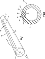
- FIGURE 1 a perspective view of a finished flexible grip for a golf club is illustrated generally at 10 and has a tubular body 14 with a substantially closed end 12 and an open end 16 indicated by dashed line which has received therein the end of a club shaft 17.
- An elongated insert indicated generally at 18 is formed in the grip during molding as will hereinafter be described in greater detail.
- FIGURE 4 one version of the golf grip of the present disclosure is shown in cross section as assembled onto a club shaft, with the insert 18 shown as extending completely through the wall thickness of the tubular grip body 14 from the interior thereof to the exterior.
- the exterior surface of the insert has been slightly deformed to provide a raised rib configuration.
- the exterior surface 20 of the rib 18 may extend outwardly from the exterior surface of the tubular body 14 by about 1 mm. This is effected by deflection or deformation of the inner surface of the insert upon assembly over the club shaft 17.
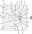
- an upper section of a compression mold 30 is shown assembled on a lower section 32 along a parting line indicated "PL" in FIGURE 3 .
- the upper section 30 of the mold has a molding cavity 34 formed therein which may have the surface thereof configured to provide graphic design or texture to the exterior surface of the grip body 14.
- the lower section of the mold 32 has a corresponding mold cavity 36, which may also be configured to provide graphic design or texture to the exterior surface of the grip body 14; and, cavity 36 has formed therein spaced ridges 38, 39 formed at the bottom thereof which have disposed therebetween the outer surface 20 of the elastomeric insert 18.
- a core bar 40 is disposed centrally in the cavities 34, 36; and, the core bar 40 has a groove 41 formed on the lower portion thereof which has received therein the inner surface 22 of the insert 18 for aiding in positioning and maintaining the insert in place during molding.
- the upper mold section 30 has a pair of downwardly extending molding sprues 42, 44 formed therein disposed respectively on opposite sides of the insert 18.
- Each the sprues 42, 44 communicates respectively with a cross passage 46, 48 respectively, which cross passages 46, 48 communicate with opposite sides of the molding cavities 34, 36.
- elastomeric material (not shown) is injected downwardly through sprues 42, 44 and passages 46, 48 into the molding cavities 34, 36 and fills these cavities and the elastomeric material (not shown) contacts and bonds to the sides 50, 52 of the insert 18 upon molding.
- a single central molding sprue 54 may be provided in the upper mold section 30 to permit injection molding of elastomer downwardly into the upper surface of cavity 34 such that the elastomer flows about the core bar and onto the sides 50, 52 of the insert 18.
- the cured grip with the insert 18 integrally molded therein is shown as it appears upon removal from the mold and removal of the core bar with the lower surface of the rib 22 shown extending slightly into the inner periphery of the body 14.
- the upper surface 20 of the rib has a groove 56, 58, respectively, adjacent each of the sides 50, 52 as formed by the ridges 38, 39 in the lower mold section 32.
- the present disclosure thus describes a unique flexible grip for a golf club having an integrated full thickness rib formed of elastomeric material having greater stiffness than the grip body.
- the insert extends fully through the wall thickness of the grip and has the upper or outer surface of the insert exposed to the exterior of the tubular grip for facilitating orientation of the grip in the user's hands and enhancing gripability.
- portions of the upper surface of the insert may extend outwardly an amount of about 1 mm.
- the increased stiffness may also be accomplished by fiber reinforcement locally or generally.
- the insert 18 may also be formed of elastomeric material having a different feel or tactile perception upon being gripped. This may be accomplished by incorporating particulate matter such as glass or sand in the material to give the surface a different discernable roughness for enhanced gripability.
- the elastomeric rib has a durometer hardness in the range of 65 to 80 on the Shore "A” scale; and, the material of the body of the tubular grip has a hardness in the range of 30-60 on the Shore "A” scale.
- the insert is assembled into a mold with the core bar; and, elastomeric material is injected into the mold cavity surrounding the core bar wherein the injected elastomer is bonded to the sides of the insert during molding.
- the insert 18 may be formed of pre-cured elastomer, may be of different elastomeric material than that of the body of the tubular grip; and, the insert may be of a different color, and of a different texture.
Landscapes
- Health & Medical Sciences (AREA)
- General Health & Medical Sciences (AREA)
- Physical Education & Sports Medicine (AREA)
- Engineering & Computer Science (AREA)
- Manufacturing & Machinery (AREA)
- Mechanical Engineering (AREA)
- Golf Clubs (AREA)
- Injection Moulding Of Plastics Or The Like (AREA)
Abstract
Description
- The present disclosure relates to flexible grips for golf clubs. Currently such grips are compression molded of elastomeric material and may have an elongated raised rib embedded on the exterior of the grip to facilitate visual and tactile orientation of the grip in the user's hands and to enhance the alignment of the club. Heretofore, the rib has been formed by designing a protruding ridge on the inner diameter surface of the grip and adding a corresponding exterior strip of elastomer on the exterior surface. The interior ridge is formed as part of the grip body material. The exterior strip of elastomer is formed of a different elastomer than the body and may have a different hardness, texture, and color to distinguish it from the grip body. When installed over a golf shaft the inner ridge compresses and deforms the elastomer and forms a raised "reminder rib" on the exterior of the grip.
- Forming the exterior strip on the grip body requires a compression molding process whereby body material parts are placed in the mold over which is placed the exterior rib strip. The placement of the exterior rib strip must be carefully and precisely controlled as well as the volume of body materials so that when the compression molding sequence occurs, the elevated temperatures and pressures in molding do not displace the exterior rib strip. In this process, it has been found difficult to maintain and control the positioning of the material for the rib during the compression molding. Where the rib is formed of material of a different color than the surrounding material of the grip, movement of the rib material during molding produces an unwanted and distorted configuration of the rib and thus, an unacceptable appearance to the product.
- Referring to
FIGURE 5 , the cross-section of a prior art flexible grip of the compression molded type employing a rib is illustrated generally at 1 and has anannular body 2 formed having anexterior rib strip 3 of elastomer disposed in arecess 4 provided in the surrounding elastomeric material which is formed by compression molding for simultaneously curing theexterior rib strip 3 and the elastomeric material of thebody 2. Thegrip 1 is shown assembled on aclub shaft 5. - It has thus been desired to find a way or means of providing a rib structure in a flexible golf grip that is more pronounced and less costly and more easily manufactured.
- The present disclosure describes a flexible grip for a golf club of the type having an exterior elongated rib on the outer surface which facilitates orientation in the user's hand and enhances gripability and which is less costly and simpler to manufacture than the compression molded ribbed golf club grips currently produced. The grip of the present disclosure employs an insert formed of elastomer extending through the full wall thickness of the tubular grip and comprised of a material having greater stiffness than that of the surrounding grip material. The insert is preferably formed separately and placed between a core bar with a groove corresponding with the interior geometry of the insert, and a surrounding mold cavity which has ridges surrounding the insert on the exterior surface of the mold cavity. The insert is secured in place by the groove in the corebar and the ridges in the mold cavity. The mold is designed with injection sprues located and oriented to direct the flow of elastomeric material injected into the mold to fill the molding cavity surrounding the core bar with elastomeric material which, upon molding, bonds to the opposite sides of the insert, thus forming an integral unitary flexible grip upon removal from the mold and removal of the core bar.
- In one version, the insert has its inner surface designed with a raised ridge such that upon assembly onto a club shaft, the elastomer is deformed such that the exterior surface of the insert is raised slightly from the exterior surface of the surrounding material of the grip to form a raised rib. If desired, the outer surface of the rib may have formed thereon grooves on either side of the exterior rib to further identify the rib and provide isolation from the grip body, which further enhances the presence of the rib. The exterior surface of the rib may have a different textured surface than the grip body for further enhancing presence and gripability. In one version of the grip of the present disclosure, the elastomeric insert has a durometer hardness in the range of 65 to 80 on the Shore "A" scale; and, the elastomer of the body of the tubular grip has a hardness in the range of 30-60 on the Shore "A" scale. Upon assembly onto a club shaft, portions of the insert may extend outwardly from the surface of the surrounding grip material by an amount not greater than 1 mm, which is the current limit specified by the United States Golf Association and the Royal And Ancient Golf Club. However, it will be understood that a raised rib height greater than 1 mm may be employed if the applicable rules of the golf game allow such.
-
-
FIGURE 1 is a perspective view of a finished flexible grip in accordance with the present disclosure as installed on the shaft of a golf club; -
FIGURE 2 is a cross-section of the grip of the present disclosure as it appears upon removal from the mold; -
FIGURE 3 is a cross-section of the mold with the insert and core bar in place before injection molding; -
FIGURE 4 is a cross-section taken along section indicating lines 4-4 ofFIGURE 1 ; and, -
FIGURE 5 is a cross-section of a prior art grip with an inlaid rib assembled onto a club shaft. - Referring to
FIGURE 1 , a perspective view of a finished flexible grip for a golf club is illustrated generally at 10 and has atubular body 14 with a substantially closedend 12 and anopen end 16 indicated by dashed line which has received therein the end of aclub shaft 17. An elongated insert indicated generally at 18 is formed in the grip during molding as will hereinafter be described in greater detail. - Referring to
FIGURE 4 , one version of the golf grip of the present disclosure is shown in cross section as assembled onto a club shaft, with theinsert 18 shown as extending completely through the wall thickness of thetubular grip body 14 from the interior thereof to the exterior. The exterior surface of the insert has been slightly deformed to provide a raised rib configuration. In the present practice, theexterior surface 20 of therib 18 may extend outwardly from the exterior surface of thetubular body 14 by about 1 mm. This is effected by deflection or deformation of the inner surface of the insert upon assembly over theclub shaft 17. - Referring to
FIGURES 2 and3 , an upper section of acompression mold 30 is shown assembled on alower section 32 along a parting line indicated "PL" inFIGURE 3 . Theupper section 30 of the mold has amolding cavity 34 formed therein which may have the surface thereof configured to provide graphic design or texture to the exterior surface of thegrip body 14. The lower section of themold 32 has acorresponding mold cavity 36, which may also be configured to provide graphic design or texture to the exterior surface of thegrip body 14; and,cavity 36 has formed therein spacedridges outer surface 20 of theelastomeric insert 18. - A
core bar 40 is disposed centrally in thecavities core bar 40 has agroove 41 formed on the lower portion thereof which has received therein theinner surface 22 of theinsert 18 for aiding in positioning and maintaining the insert in place during molding. - The
upper mold section 30 has a pair of downwardly extendingmolding sprues insert 18. Each thesprues cross passage passages molding cavities core bar 40 and insert 18 in place, elastomeric material (not shown) is injected downwardly throughsprues passages molding cavities sides insert 18 upon molding. Alternatively, a single central molding sprue 54, shown in dashed outline, may be provided in theupper mold section 30 to permit injection molding of elastomer downwardly into the upper surface ofcavity 34 such that the elastomer flows about the core bar and onto thesides insert 18. - Referring to
FIGURE 2 , the cured grip with theinsert 18 integrally molded therein is shown as it appears upon removal from the mold and removal of the core bar with the lower surface of therib 22 shown extending slightly into the inner periphery of thebody 14. Theupper surface 20 of the rib has agroove sides ridges lower mold section 32. - The present disclosure thus describes a unique flexible grip for a golf club having an integrated full thickness rib formed of elastomeric material having greater stiffness than the grip body. The insert extends fully through the wall thickness of the grip and has the upper or outer surface of the insert exposed to the exterior of the tubular grip for facilitating orientation of the grip in the user's hands and enhancing gripability. Upon assembly of the cured grip onto a club shaft, portions of the upper surface of the insert may extend outwardly an amount of about 1 mm. In the present practice, it has been found satisfactory to form the
insert 18 of elastomeric material having a stiffness at least ten percent (10%) greater than that of material of thetubular body 14. The increased stiffness may also be accomplished by fiber reinforcement locally or generally. Theinsert 18 may also be formed of elastomeric material having a different feel or tactile perception upon being gripped. This may be accomplished by incorporating particulate matter such as glass or sand in the material to give the surface a different discernable roughness for enhanced gripability. In the present practice, the elastomeric rib has a durometer hardness in the range of 65 to 80 on the Shore "A" scale; and, the material of the body of the tubular grip has a hardness in the range of 30-60 on the Shore "A" scale. In the practice of the method of the present disclosure, the insert is assembled into a mold with the core bar; and, elastomeric material is injected into the mold cavity surrounding the core bar wherein the injected elastomer is bonded to the sides of the insert during molding. In the present practice, theinsert 18 may be formed of pre-cured elastomer, may be of different elastomeric material than that of the body of the tubular grip; and, the insert may be of a different color, and of a different texture. - The exemplary embodiment has been described and illustrated with reference to the drawings. Obviously, modifications and alterations will occur to others upon reading and understanding the preceding detailed description. It is intended that the exemplary embodiment be construed as including all such modifications and alterations insofar as they come within the scope of the appended claims or the equivalents thereof.
Parts list 10 grip G/ T 1 Prior Art grip G/ T 12 closed end of tubular body 2 tubular body 14 tubular body 3 rib insert 16 open end of tubular body 4 groove in body OD 17 club shaft 5 club shaft 18 insert G/ T 20 insert outer surface 22 insert inner surface 24 not used 26 " " " 28 " " " 30 upper mold section 32 lower mold section 34 upper mold cavity 36 lower mold cavity 38 ridges in 36 39 " " " " 40 core bar 41 core bar groove 42 sprues 44 " " 46 cross passages 48 " " " " 50 sides of insert 52 " " " " 54 single central sprue 56 grooves adjacent insert 58 " " " " " "
Claims (9)
- A flexible tubular grip for being received over the shaft of a golf club comprising:(a) a tubular member formed of elastomeric material having a substantially closed end and an open end;(b) an elongated insert disposed in the tubular member and having a first surface exposed to the outer surface of the tubular member with the insert extending inwardly completely through the wall of the tubular member to have a second surface opposite the first surface exposed to the inner periphery of the tubular member.
- The grip of claim 1, wherein the insert is formed of pre-cured elastomeric material.
- The grip of claim 2, wherein the insert is formed of elastomeric material having a durometer hardness in range of 65 to 80 on the Shore "A" scale.
- The grip of claim 1, wherein the insert is formed of elastomeric material of one of (i) a different color than the elastomeric material of the tubular member, and (ii) elastomeric material having at least 10 percent (10%) greater stiffness from that of the tubular body.
- The grip of claim 1, wherein the insert is formed of elastomeric material of one of (i) a different texture than the elastomeric material of the tubular member, and (ii) a material having a greater hardness.
- The grip of claim 1, wherein the insert first surface extends outwardly of the outer surface of the tubular member.
- The grip of claim 6, wherein the insert first surface extends outwardly of the outer surface of the tubular member by an amount not greater than 1 mm.
- The grip of claim 1, wherein the insert is formed of flexible material.
- The grip of claim 1, wherein the insert is formed of elastomeric material.
Applications Claiming Priority (1)
| Application Number | Priority Date | Filing Date | Title |
|---|---|---|---|
| US15/916,401 US10293230B1 (en) | 2018-03-09 | 2018-03-09 | Flexible golf grip with full thickness rib section and method of making same |
Publications (2)
| Publication Number | Publication Date |
|---|---|
| EP3536387A1 true EP3536387A1 (en) | 2019-09-11 |
| EP3536387B1 EP3536387B1 (en) | 2020-09-16 |
Family
ID=65817735
Family Applications (1)
| Application Number | Title | Priority Date | Filing Date |
|---|---|---|---|
| EP19161764.6A Active EP3536387B1 (en) | 2018-03-09 | 2019-03-08 | Flexible golf grip with full thickness rib section and method of making same |
Country Status (4)
| Country | Link |
|---|---|
| US (2) | US10293230B1 (en) |
| EP (1) | EP3536387B1 (en) |
| JP (1) | JP7541433B2 (en) |
| KR (1) | KR102629317B1 (en) |
Families Citing this family (5)
| Publication number | Priority date | Publication date | Assignee | Title |
|---|---|---|---|---|
| US10052538B2 (en) | 2016-09-20 | 2018-08-21 | Eaton Intelligent Power, Ltd. | Golf grip with reminder rib |
| KR102071332B1 (en) * | 2016-10-20 | 2020-01-30 | 김경호 | Grip for golf club |
| WO2021261732A1 (en) * | 2020-06-22 | 2021-12-30 | 김상훈 | Golf swing aiding mechanism |
| US11752410B2 (en) | 2021-09-28 | 2023-09-12 | Bradley R. Mason | Force sensor for alerting golfer when club held too tightly |
| US20230191212A1 (en) * | 2021-12-22 | 2023-06-22 | Eaton Intelligent Power Limited | Golf club grip with reminder rib |
Citations (5)
| Publication number | Priority date | Publication date | Assignee | Title |
|---|---|---|---|---|
| US3028283A (en) * | 1956-03-14 | 1962-04-03 | Macgregor Sport Products Inc | Method of making golf club grip |
| US3706453A (en) * | 1970-11-02 | 1972-12-19 | Northwestern Golf Co | Golf club with finger orienting grip |
| US5322290A (en) * | 1990-12-30 | 1994-06-21 | Maruman Golf Kabushiki Kaisha | Golf club grip |
| JP2000176061A (en) * | 1998-12-15 | 2000-06-27 | Sumitomo Rubber Ind Ltd | Golf club grip |
| US6666777B1 (en) * | 2002-08-28 | 2003-12-23 | Lamkin Corp. | Partial cord golf grip and method of making same |
Family Cites Families (18)
| Publication number | Priority date | Publication date | Assignee | Title |
|---|---|---|---|---|
| JPH03112576A (en) * | 1989-09-28 | 1991-05-14 | Kinugawa Rubber Ind Co Ltd | Golf grip made of synthetic resin |
| US5261665A (en) * | 1992-02-11 | 1993-11-16 | Robert A. Paley, Inc. | Golf club grip formed of a plurality of materials and method of manufacture thereof |
| US5897440A (en) * | 1997-09-05 | 1999-04-27 | Graman U.S.A., Inc. | Nodule golf shaft grip |
| JP3567098B2 (en) * | 1999-03-19 | 2004-09-15 | 丸五ゴム工業株式会社 | Method of forming grip for golf club |
| JP2003180892A (en) | 2001-10-10 | 2003-07-02 | Yuji Yoshiyasu | Golf club grip |
| US20030228929A1 (en) * | 2002-06-11 | 2003-12-11 | Hiroshi Miyasu | Grip for golf club |
| TW588669U (en) * | 2002-08-07 | 2004-05-21 | Hong-Sung Chu | Handle of golf club with easily foldable structure |
| US7749094B2 (en) | 2003-12-29 | 2010-07-06 | Chen Yung Hsiang | Golf club grip and manufacturing method thereof |
| US7435186B1 (en) * | 2004-02-23 | 2008-10-14 | Miller R Lee | Golf club grip |
| JP4153924B2 (en) * | 2005-04-28 | 2008-09-24 | 株式会社ホンダアクセス | grip |
| US20060287123A1 (en) * | 2005-06-21 | 2006-12-21 | Jack Wang | Grip |
| US7458903B2 (en) | 2006-06-08 | 2008-12-02 | Eaton Corporation | Hand grip and method of making same |
| US7458902B2 (en) | 2007-03-14 | 2008-12-02 | Eaton Corporation | Changeable golf grip |
| US20110172024A1 (en) * | 2009-03-25 | 2011-07-14 | Lu Clive S | Grip for sporting equipment |
| US8296907B2 (en) | 2009-05-15 | 2012-10-30 | Eaton Corporation | Light weight grip and method of making same |
| US8485916B2 (en) | 2009-05-22 | 2013-07-16 | Eaton | Apparatus and method for forming a reminder rib in a grip |
| JP3155820U (en) | 2009-09-18 | 2009-12-03 | チェン ユンシャンChen, Yung−Hsiang | Golf club grip with three-dimensional decoration design and molding die thereof |
| US20160271467A1 (en) * | 2015-01-19 | 2016-09-22 | Jbd Holdings Inc. | Texturized golf grip surfaces |
-
2018
- 2018-03-09 US US15/916,401 patent/US10293230B1/en active Active
-
2019
- 2019-03-07 KR KR1020190026520A patent/KR102629317B1/en active Active
- 2019-03-08 EP EP19161764.6A patent/EP3536387B1/en active Active
- 2019-03-08 JP JP2019042262A patent/JP7541433B2/en active Active
- 2019-03-18 US US16/356,065 patent/US10543411B2/en active Active
Patent Citations (5)
| Publication number | Priority date | Publication date | Assignee | Title |
|---|---|---|---|---|
| US3028283A (en) * | 1956-03-14 | 1962-04-03 | Macgregor Sport Products Inc | Method of making golf club grip |
| US3706453A (en) * | 1970-11-02 | 1972-12-19 | Northwestern Golf Co | Golf club with finger orienting grip |
| US5322290A (en) * | 1990-12-30 | 1994-06-21 | Maruman Golf Kabushiki Kaisha | Golf club grip |
| JP2000176061A (en) * | 1998-12-15 | 2000-06-27 | Sumitomo Rubber Ind Ltd | Golf club grip |
| US6666777B1 (en) * | 2002-08-28 | 2003-12-23 | Lamkin Corp. | Partial cord golf grip and method of making same |
Also Published As
| Publication number | Publication date |
|---|---|
| KR20190106797A (en) | 2019-09-18 |
| US20190275395A1 (en) | 2019-09-12 |
| EP3536387B1 (en) | 2020-09-16 |
| US10293230B1 (en) | 2019-05-21 |
| US10543411B2 (en) | 2020-01-28 |
| JP7541433B2 (en) | 2024-08-28 |
| JP2019155098A (en) | 2019-09-19 |
| KR102629317B1 (en) | 2024-01-24 |
Similar Documents
| Publication | Publication Date | Title |
|---|---|---|
| EP3536387B1 (en) | Flexible golf grip with full thickness rib section and method of making same | |
| AU2022259805B2 (en) | Golf grip with reminder rib | |
| US2604660A (en) | Mold and method for forming grips for golf clubs and the like | |
| US3211455A (en) | Supple striking face for golf putters | |
| EP2253356B1 (en) | Appartus and method for forming a reminder rib in a grip | |
| US20090174116A1 (en) | Flexible grip and method of making same | |
| US4186924A (en) | Arthritic golf club grip | |
| KR102499567B1 (en) | Double Injection Moulding Golf Club Grip | |
| US10143902B1 (en) | Flexible grip for a golf club and method of making same | |
| US20200406113A1 (en) | Flexible grip with intermediate member | |
| JP3892571B2 (en) | Manufacturing method of rubber crawler | |
| JPH06285190A (en) | Manufacture of golf club head | |
| CN212888722U (en) | Breathing mask mold mechanism | |
| JP3663580B2 (en) | Golf ball core manufacturing method | |
| KR102802228B1 (en) | Manufacturing Method Grip For Golf Club and The Grip | |
| JP4899847B2 (en) | Golf club grip | |
| JPH06305460A (en) | Structure and manufacture of rubber crawler | |
| JPH0651003B2 (en) | Molding method for multicolor soles with different colored tapes | |
| JPH0824727B2 (en) | Manufacturing method of golf club head | |
| EP3028833A1 (en) | Handle and method, system and apparatus for manufacturing same | |
| JPS6167108U (en) | ||
| JPH0442864U (en) | ||
| JPH08285082A (en) | Laminated o-ring and manufacture thereof | |
| JPH04283142A (en) | Steering wheel pad |
Legal Events
| Date | Code | Title | Description |
|---|---|---|---|
| PUAI | Public reference made under article 153(3) epc to a published international application that has entered the european phase |
Free format text: ORIGINAL CODE: 0009012 |
|
| STAA | Information on the status of an ep patent application or granted ep patent |
Free format text: STATUS: REQUEST FOR EXAMINATION WAS MADE |
|
| 17P | Request for examination filed |
Effective date: 20190308 |
|
| AK | Designated contracting states |
Kind code of ref document: A1 Designated state(s): AL AT BE BG CH CY CZ DE DK EE ES FI FR GB GR HR HU IE IS IT LI LT LU LV MC MK MT NL NO PL PT RO RS SE SI SK SM TR |
|
| AX | Request for extension of the european patent |
Extension state: BA ME |
|
| GRAP | Despatch of communication of intention to grant a patent |
Free format text: ORIGINAL CODE: EPIDOSNIGR1 |
|
| STAA | Information on the status of an ep patent application or granted ep patent |
Free format text: STATUS: GRANT OF PATENT IS INTENDED |
|
| RIC1 | Information provided on ipc code assigned before grant |
Ipc: B29C 45/37 20060101ALI20200325BHEP Ipc: A63B 53/14 20150101ALI20200325BHEP Ipc: B29C 45/14 20060101ALI20200325BHEP Ipc: A63B 60/08 20150101ALI20200325BHEP Ipc: A63B 60/14 20150101AFI20200325BHEP Ipc: B29C 33/42 20060101ALI20200325BHEP Ipc: A63B 60/10 20150101ALI20200325BHEP Ipc: B29C 45/26 20060101ALI20200325BHEP |
|
| RAP1 | Party data changed (applicant data changed or rights of an application transferred) |
Owner name: EATON INTELLIGENT POWER LIMITED |
|
| INTG | Intention to grant announced |
Effective date: 20200415 |
|
| GRAS | Grant fee paid |
Free format text: ORIGINAL CODE: EPIDOSNIGR3 |
|
| GRAA | (expected) grant |
Free format text: ORIGINAL CODE: 0009210 |
|
| STAA | Information on the status of an ep patent application or granted ep patent |
Free format text: STATUS: THE PATENT HAS BEEN GRANTED |
|
| AK | Designated contracting states |
Kind code of ref document: B1 Designated state(s): AL AT BE BG CH CY CZ DE DK EE ES FI FR GB GR HR HU IE IS IT LI LT LU LV MC MK MT NL NO PL PT RO RS SE SI SK SM TR |
|
| REG | Reference to a national code |
Ref country code: GB Ref legal event code: FG4D |
|
| REG | Reference to a national code |
Ref country code: CH Ref legal event code: EP |
|
| REG | Reference to a national code |
Ref country code: DE Ref legal event code: R096 Ref document number: 602019000674 Country of ref document: DE |
|
| REG | Reference to a national code |
Ref country code: IE Ref legal event code: FG4D |
|
| REG | Reference to a national code |
Ref country code: AT Ref legal event code: REF Ref document number: 1313632 Country of ref document: AT Kind code of ref document: T Effective date: 20201015 |
|
| PG25 | Lapsed in a contracting state [announced via postgrant information from national office to epo] |
Ref country code: SE Free format text: LAPSE BECAUSE OF FAILURE TO SUBMIT A TRANSLATION OF THE DESCRIPTION OR TO PAY THE FEE WITHIN THE PRESCRIBED TIME-LIMIT Effective date: 20200916 Ref country code: GR Free format text: LAPSE BECAUSE OF FAILURE TO SUBMIT A TRANSLATION OF THE DESCRIPTION OR TO PAY THE FEE WITHIN THE PRESCRIBED TIME-LIMIT Effective date: 20201217 Ref country code: HR Free format text: LAPSE BECAUSE OF FAILURE TO SUBMIT A TRANSLATION OF THE DESCRIPTION OR TO PAY THE FEE WITHIN THE PRESCRIBED TIME-LIMIT Effective date: 20200916 Ref country code: NO Free format text: LAPSE BECAUSE OF FAILURE TO SUBMIT A TRANSLATION OF THE DESCRIPTION OR TO PAY THE FEE WITHIN THE PRESCRIBED TIME-LIMIT Effective date: 20201216 Ref country code: FI Free format text: LAPSE BECAUSE OF FAILURE TO SUBMIT A TRANSLATION OF THE DESCRIPTION OR TO PAY THE FEE WITHIN THE PRESCRIBED TIME-LIMIT Effective date: 20200916 Ref country code: BG Free format text: LAPSE BECAUSE OF FAILURE TO SUBMIT A TRANSLATION OF THE DESCRIPTION OR TO PAY THE FEE WITHIN THE PRESCRIBED TIME-LIMIT Effective date: 20201216 |
|
| REG | Reference to a national code |
Ref country code: AT Ref legal event code: MK05 Ref document number: 1313632 Country of ref document: AT Kind code of ref document: T Effective date: 20200916 |
|
| REG | Reference to a national code |
Ref country code: NL Ref legal event code: MP Effective date: 20200916 |
|
| PG25 | Lapsed in a contracting state [announced via postgrant information from national office to epo] |
Ref country code: LV Free format text: LAPSE BECAUSE OF FAILURE TO SUBMIT A TRANSLATION OF THE DESCRIPTION OR TO PAY THE FEE WITHIN THE PRESCRIBED TIME-LIMIT Effective date: 20200916 Ref country code: RS Free format text: LAPSE BECAUSE OF FAILURE TO SUBMIT A TRANSLATION OF THE DESCRIPTION OR TO PAY THE FEE WITHIN THE PRESCRIBED TIME-LIMIT Effective date: 20200916 |
|
| REG | Reference to a national code |
Ref country code: LT Ref legal event code: MG4D |
|
| PG25 | Lapsed in a contracting state [announced via postgrant information from national office to epo] |
Ref country code: SM Free format text: LAPSE BECAUSE OF FAILURE TO SUBMIT A TRANSLATION OF THE DESCRIPTION OR TO PAY THE FEE WITHIN THE PRESCRIBED TIME-LIMIT Effective date: 20200916 Ref country code: LT Free format text: LAPSE BECAUSE OF FAILURE TO SUBMIT A TRANSLATION OF THE DESCRIPTION OR TO PAY THE FEE WITHIN THE PRESCRIBED TIME-LIMIT Effective date: 20200916 Ref country code: EE Free format text: LAPSE BECAUSE OF FAILURE TO SUBMIT A TRANSLATION OF THE DESCRIPTION OR TO PAY THE FEE WITHIN THE PRESCRIBED TIME-LIMIT Effective date: 20200916 Ref country code: RO Free format text: LAPSE BECAUSE OF FAILURE TO SUBMIT A TRANSLATION OF THE DESCRIPTION OR TO PAY THE FEE WITHIN THE PRESCRIBED TIME-LIMIT Effective date: 20200916 Ref country code: PT Free format text: LAPSE BECAUSE OF FAILURE TO SUBMIT A TRANSLATION OF THE DESCRIPTION OR TO PAY THE FEE WITHIN THE PRESCRIBED TIME-LIMIT Effective date: 20210118 Ref country code: CZ Free format text: LAPSE BECAUSE OF FAILURE TO SUBMIT A TRANSLATION OF THE DESCRIPTION OR TO PAY THE FEE WITHIN THE PRESCRIBED TIME-LIMIT Effective date: 20200916 |
|
| PG25 | Lapsed in a contracting state [announced via postgrant information from national office to epo] |
Ref country code: PL Free format text: LAPSE BECAUSE OF FAILURE TO SUBMIT A TRANSLATION OF THE DESCRIPTION OR TO PAY THE FEE WITHIN THE PRESCRIBED TIME-LIMIT Effective date: 20200916 Ref country code: IS Free format text: LAPSE BECAUSE OF FAILURE TO SUBMIT A TRANSLATION OF THE DESCRIPTION OR TO PAY THE FEE WITHIN THE PRESCRIBED TIME-LIMIT Effective date: 20210116 Ref country code: ES Free format text: LAPSE BECAUSE OF FAILURE TO SUBMIT A TRANSLATION OF THE DESCRIPTION OR TO PAY THE FEE WITHIN THE PRESCRIBED TIME-LIMIT Effective date: 20200916 Ref country code: AT Free format text: LAPSE BECAUSE OF FAILURE TO SUBMIT A TRANSLATION OF THE DESCRIPTION OR TO PAY THE FEE WITHIN THE PRESCRIBED TIME-LIMIT Effective date: 20200916 Ref country code: AL Free format text: LAPSE BECAUSE OF FAILURE TO SUBMIT A TRANSLATION OF THE DESCRIPTION OR TO PAY THE FEE WITHIN THE PRESCRIBED TIME-LIMIT Effective date: 20200916 |
|
| REG | Reference to a national code |
Ref country code: DE Ref legal event code: R097 Ref document number: 602019000674 Country of ref document: DE |
|
| PG25 | Lapsed in a contracting state [announced via postgrant information from national office to epo] |
Ref country code: SK Free format text: LAPSE BECAUSE OF FAILURE TO SUBMIT A TRANSLATION OF THE DESCRIPTION OR TO PAY THE FEE WITHIN THE PRESCRIBED TIME-LIMIT Effective date: 20200916 |
|
| PLBE | No opposition filed within time limit |
Free format text: ORIGINAL CODE: 0009261 |
|
| STAA | Information on the status of an ep patent application or granted ep patent |
Free format text: STATUS: NO OPPOSITION FILED WITHIN TIME LIMIT |
|
| 26N | No opposition filed |
Effective date: 20210617 |
|
| PG25 | Lapsed in a contracting state [announced via postgrant information from national office to epo] |
Ref country code: DK Free format text: LAPSE BECAUSE OF FAILURE TO SUBMIT A TRANSLATION OF THE DESCRIPTION OR TO PAY THE FEE WITHIN THE PRESCRIBED TIME-LIMIT Effective date: 20200916 Ref country code: SI Free format text: LAPSE BECAUSE OF FAILURE TO SUBMIT A TRANSLATION OF THE DESCRIPTION OR TO PAY THE FEE WITHIN THE PRESCRIBED TIME-LIMIT Effective date: 20200916 |
|
| REG | Reference to a national code |
Ref country code: DE Ref legal event code: R119 Ref document number: 602019000674 Country of ref document: DE |
|
| PG25 | Lapsed in a contracting state [announced via postgrant information from national office to epo] |
Ref country code: MC Free format text: LAPSE BECAUSE OF FAILURE TO SUBMIT A TRANSLATION OF THE DESCRIPTION OR TO PAY THE FEE WITHIN THE PRESCRIBED TIME-LIMIT Effective date: 20200916 Ref country code: IT Free format text: LAPSE BECAUSE OF FAILURE TO SUBMIT A TRANSLATION OF THE DESCRIPTION OR TO PAY THE FEE WITHIN THE PRESCRIBED TIME-LIMIT Effective date: 20200916 |
|
| REG | Reference to a national code |
Ref country code: BE Ref legal event code: MM Effective date: 20210331 |
|
| PG25 | Lapsed in a contracting state [announced via postgrant information from national office to epo] |
Ref country code: FR Free format text: LAPSE BECAUSE OF NON-PAYMENT OF DUE FEES Effective date: 20210331 Ref country code: DE Free format text: LAPSE BECAUSE OF NON-PAYMENT OF DUE FEES Effective date: 20211001 Ref country code: LU Free format text: LAPSE BECAUSE OF NON-PAYMENT OF DUE FEES Effective date: 20210308 |
|
| PG25 | Lapsed in a contracting state [announced via postgrant information from national office to epo] |
Ref country code: BE Free format text: LAPSE BECAUSE OF NON-PAYMENT OF DUE FEES Effective date: 20210331 |
|
| REG | Reference to a national code |
Ref country code: CH Ref legal event code: PL |
|
| PG25 | Lapsed in a contracting state [announced via postgrant information from national office to epo] |
Ref country code: LI Free format text: LAPSE BECAUSE OF NON-PAYMENT OF DUE FEES Effective date: 20220331 Ref country code: CH Free format text: LAPSE BECAUSE OF NON-PAYMENT OF DUE FEES Effective date: 20220331 |
|
| P01 | Opt-out of the competence of the unified patent court (upc) registered |
Effective date: 20230521 |
|
| PG25 | Lapsed in a contracting state [announced via postgrant information from national office to epo] |
Ref country code: NL Free format text: LAPSE BECAUSE OF NON-PAYMENT OF DUE FEES Effective date: 20200923 Ref country code: CY Free format text: LAPSE BECAUSE OF FAILURE TO SUBMIT A TRANSLATION OF THE DESCRIPTION OR TO PAY THE FEE WITHIN THE PRESCRIBED TIME-LIMIT Effective date: 20200916 |
|
| PG25 | Lapsed in a contracting state [announced via postgrant information from national office to epo] |
Ref country code: HU Free format text: LAPSE BECAUSE OF FAILURE TO SUBMIT A TRANSLATION OF THE DESCRIPTION OR TO PAY THE FEE WITHIN THE PRESCRIBED TIME-LIMIT; INVALID AB INITIO Effective date: 20190308 |
|
| PG25 | Lapsed in a contracting state [announced via postgrant information from national office to epo] |
Ref country code: MK Free format text: LAPSE BECAUSE OF FAILURE TO SUBMIT A TRANSLATION OF THE DESCRIPTION OR TO PAY THE FEE WITHIN THE PRESCRIBED TIME-LIMIT Effective date: 20200916 |
|
| PG25 | Lapsed in a contracting state [announced via postgrant information from national office to epo] |
Ref country code: TR Free format text: LAPSE BECAUSE OF FAILURE TO SUBMIT A TRANSLATION OF THE DESCRIPTION OR TO PAY THE FEE WITHIN THE PRESCRIBED TIME-LIMIT Effective date: 20200916 |
|
| PG25 | Lapsed in a contracting state [announced via postgrant information from national office to epo] |
Ref country code: MT Free format text: LAPSE BECAUSE OF FAILURE TO SUBMIT A TRANSLATION OF THE DESCRIPTION OR TO PAY THE FEE WITHIN THE PRESCRIBED TIME-LIMIT Effective date: 20200916 |
|
| PGFP | Annual fee paid to national office [announced via postgrant information from national office to epo] |
Ref country code: GB Payment date: 20260220 Year of fee payment: 8 |
|
| PGFP | Annual fee paid to national office [announced via postgrant information from national office to epo] |
Ref country code: IE Payment date: 20260223 Year of fee payment: 8 |