EP3536295B1 - Electric wheel chair - Google Patents
Electric wheel chair Download PDFInfo
- Publication number
- EP3536295B1 EP3536295B1 EP19159714.5A EP19159714A EP3536295B1 EP 3536295 B1 EP3536295 B1 EP 3536295B1 EP 19159714 A EP19159714 A EP 19159714A EP 3536295 B1 EP3536295 B1 EP 3536295B1
- Authority
- EP
- European Patent Office
- Prior art keywords
- frame portion
- vehicle body
- caregiver
- electric wheelchair
- rotors
- Prior art date
- Legal status (The legal status is an assumption and is not a legal conclusion. Google has not performed a legal analysis and makes no representation as to the accuracy of the status listed.)
- Not-in-force
Links
Images




Classifications
-
- A—HUMAN NECESSITIES
- A61—MEDICAL OR VETERINARY SCIENCE; HYGIENE
- A61G—TRANSPORT, PERSONAL CONVEYANCES, OR ACCOMMODATION SPECIALLY ADAPTED FOR PATIENTS OR DISABLED PERSONS; OPERATING TABLES OR CHAIRS; CHAIRS FOR DENTISTRY; FUNERAL DEVICES
- A61G5/00—Chairs or personal conveyances specially adapted for patients or disabled persons, e.g. wheelchairs
- A61G5/04—Chairs or personal conveyances specially adapted for patients or disabled persons, e.g. wheelchairs motor-driven
-
- A—HUMAN NECESSITIES
- A61—MEDICAL OR VETERINARY SCIENCE; HYGIENE
- A61G—TRANSPORT, PERSONAL CONVEYANCES, OR ACCOMMODATION SPECIALLY ADAPTED FOR PATIENTS OR DISABLED PERSONS; OPERATING TABLES OR CHAIRS; CHAIRS FOR DENTISTRY; FUNERAL DEVICES
- A61G5/00—Chairs or personal conveyances specially adapted for patients or disabled persons, e.g. wheelchairs
- A61G5/04—Chairs or personal conveyances specially adapted for patients or disabled persons, e.g. wheelchairs motor-driven
- A61G5/041—Chairs or personal conveyances specially adapted for patients or disabled persons, e.g. wheelchairs motor-driven having a specific drive-type
- A61G5/042—Front wheel drive
-
- A—HUMAN NECESSITIES
- A61—MEDICAL OR VETERINARY SCIENCE; HYGIENE
- A61G—TRANSPORT, PERSONAL CONVEYANCES, OR ACCOMMODATION SPECIALLY ADAPTED FOR PATIENTS OR DISABLED PERSONS; OPERATING TABLES OR CHAIRS; CHAIRS FOR DENTISTRY; FUNERAL DEVICES
- A61G5/00—Chairs or personal conveyances specially adapted for patients or disabled persons, e.g. wheelchairs
- A61G5/10—Parts, details or accessories
-
- A—HUMAN NECESSITIES
- A61—MEDICAL OR VETERINARY SCIENCE; HYGIENE
- A61G—TRANSPORT, PERSONAL CONVEYANCES, OR ACCOMMODATION SPECIALLY ADAPTED FOR PATIENTS OR DISABLED PERSONS; OPERATING TABLES OR CHAIRS; CHAIRS FOR DENTISTRY; FUNERAL DEVICES
- A61G5/00—Chairs or personal conveyances specially adapted for patients or disabled persons, e.g. wheelchairs
- A61G5/10—Parts, details or accessories
- A61G5/1089—Anti-tip devices
-
- B—PERFORMING OPERATIONS; TRANSPORTING
- B62—LAND VEHICLES FOR TRAVELLING OTHERWISE THAN ON RAILS
- B62B—HAND-PROPELLED VEHICLES, e.g. HAND CARTS OR PERAMBULATORS; SLEDGES
- B62B5/00—Accessories or details specially adapted for hand carts
- B62B5/08—Children's seats ; Seats or supports for other persons
- B62B5/087—Platforms to stand upon
-
- A—HUMAN NECESSITIES
- A61—MEDICAL OR VETERINARY SCIENCE; HYGIENE
- A61G—TRANSPORT, PERSONAL CONVEYANCES, OR ACCOMMODATION SPECIALLY ADAPTED FOR PATIENTS OR DISABLED PERSONS; OPERATING TABLES OR CHAIRS; CHAIRS FOR DENTISTRY; FUNERAL DEVICES
- A61G2203/00—General characteristics of devices
- A61G2203/10—General characteristics of devices characterised by specific control means, e.g. for adjustment or steering
-
- A—HUMAN NECESSITIES
- A61—MEDICAL OR VETERINARY SCIENCE; HYGIENE
- A61G—TRANSPORT, PERSONAL CONVEYANCES, OR ACCOMMODATION SPECIALLY ADAPTED FOR PATIENTS OR DISABLED PERSONS; OPERATING TABLES OR CHAIRS; CHAIRS FOR DENTISTRY; FUNERAL DEVICES
- A61G2203/00—General characteristics of devices
- A61G2203/10—General characteristics of devices characterised by specific control means, e.g. for adjustment or steering
- A61G2203/14—Joysticks
-
- A—HUMAN NECESSITIES
- A61—MEDICAL OR VETERINARY SCIENCE; HYGIENE
- A61G—TRANSPORT, PERSONAL CONVEYANCES, OR ACCOMMODATION SPECIALLY ADAPTED FOR PATIENTS OR DISABLED PERSONS; OPERATING TABLES OR CHAIRS; CHAIRS FOR DENTISTRY; FUNERAL DEVICES
- A61G2203/00—General characteristics of devices
- A61G2203/30—General characteristics of devices characterised by sensor means
- A61G2203/36—General characteristics of devices characterised by sensor means for motion
-
- A—HUMAN NECESSITIES
- A61—MEDICAL OR VETERINARY SCIENCE; HYGIENE
- A61G—TRANSPORT, PERSONAL CONVEYANCES, OR ACCOMMODATION SPECIALLY ADAPTED FOR PATIENTS OR DISABLED PERSONS; OPERATING TABLES OR CHAIRS; CHAIRS FOR DENTISTRY; FUNERAL DEVICES
- A61G2203/00—General characteristics of devices
- A61G2203/70—General characteristics of devices with special adaptations, e.g. for safety or comfort
-
- B—PERFORMING OPERATIONS; TRANSPORTING
- B60—VEHICLES IN GENERAL
- B60Y—INDEXING SCHEME RELATING TO ASPECTS CROSS-CUTTING VEHICLE TECHNOLOGY
- B60Y2200/00—Type of vehicle
- B60Y2200/80—Other vehicles not covered by groups B60Y2200/10 - B60Y2200/60
- B60Y2200/84—Wheelchairs
-
- B—PERFORMING OPERATIONS; TRANSPORTING
- B62—LAND VEHICLES FOR TRAVELLING OTHERWISE THAN ON RAILS
- B62B—HAND-PROPELLED VEHICLES, e.g. HAND CARTS OR PERAMBULATORS; SLEDGES
- B62B2202/00—Indexing codes relating to type or characteristics of transported articles
- B62B2202/42—Persons or animals, dead or alive
-
- B—PERFORMING OPERATIONS; TRANSPORTING
- B62—LAND VEHICLES FOR TRAVELLING OTHERWISE THAN ON RAILS
- B62B—HAND-PROPELLED VEHICLES, e.g. HAND CARTS OR PERAMBULATORS; SLEDGES
- B62B3/00—Hand carts having more than one axis carrying transport wheels; Steering devices therefor; Equipment therefor
- B62B3/001—Steering devices
-
- B—PERFORMING OPERATIONS; TRANSPORTING
- B62—LAND VEHICLES FOR TRAVELLING OTHERWISE THAN ON RAILS
- B62B—HAND-PROPELLED VEHICLES, e.g. HAND CARTS OR PERAMBULATORS; SLEDGES
- B62B5/00—Accessories or details specially adapted for hand carts
- B62B5/0026—Propulsion aids
- B62B5/0033—Electric motors
-
- B—PERFORMING OPERATIONS; TRANSPORTING
- B62—LAND VEHICLES FOR TRAVELLING OTHERWISE THAN ON RAILS
- B62B—HAND-PROPELLED VEHICLES, e.g. HAND CARTS OR PERAMBULATORS; SLEDGES
- B62B5/00—Accessories or details specially adapted for hand carts
- B62B5/0026—Propulsion aids
- B62B5/0069—Control
-
- B—PERFORMING OPERATIONS; TRANSPORTING
- B62—LAND VEHICLES FOR TRAVELLING OTHERWISE THAN ON RAILS
- B62B—HAND-PROPELLED VEHICLES, e.g. HAND CARTS OR PERAMBULATORS; SLEDGES
- B62B5/00—Accessories or details specially adapted for hand carts
- B62B5/08—Children's seats ; Seats or supports for other persons
- B62B5/085—Resting seats
Definitions
- the present invention relates to an electric wheel chair, particularly to an electric wheel chair that enables a caregiver to ride thereon and is capable of being actuated by a prime mover.
- WO 2017/143454 A1 discloses a manual wheelchair having an upper frame in form of a seat portion enabling a user to ride on and a lower frame with drive wheels and guiding wheels, wherein the seat portion can be tilted relative to the lower frame around a horizontal central axis coincident with the rotation axis of the drive wheels. This enables that the pivot center of the seat portion is coincident at any moment and any position with the rotation axis of the drive wheel allowing to maintain a constant distance between a user's and each pushrim of each drive wheel. Thus, it is easier for the user to push the drive wheels in any tilted position.
- the riding portion for the caregiver is provided as an additional component to the vehicle body. This leaves concern that increase in size of the well-known electric wheelchairs is inevitable. Moreover, in the well-known electric wheelchairs, change in balance of the center of gravity occurs between a condition that the caregiver rides on the riding portion and a condition that the caregiver gets off the riding portion. Hence, it is difficult to stably actuate the well-known electric wheelchairs.
- the present invention is made in view of the aforementioned drawbacks. It is an object of the present invention to provide an electric wheelchair realized in compact size. Besides, it is another object of the present invention to provide an electric wheelchair capable of being stably actuated.
- a moving device in the form of an electric wheelchair is an electric wheelchair that is enabled to be actuated by a prime mover including a motor and enables a caregiver to ride thereon.
- the moving device includes a vehicle body and a plurality of rotors (a plurality of rolling elements).
- the vehicle body includes a first frame portion and a second frame portion.
- the second frame portion enables the caregiver to ride thereon.
- the first frame portion enables a care receiver taken care of by the caregiver to ride thereon.
- the plurality of rotors are provided on the second frame portion, and are rotatable in movement of the vehicle body.
- a wheel base defined by a distance between axes of the plurality of rotors is constant.
- the first frame portion is provided on the second frame portion so as to be movable in accordance with a motion of the caregiver riding on and getting off the first frame portion.
- the first frame portion is movable between a first position and a second position with respect to the second frame portion.
- the first position enables both the caregiver and the care receiver to ride on the vehicle body.
- the second position enables only the care receiver to ride on the vehicle body.
- the present electric wheelchair enables both the caregiver and the care receiver to ride thereon or enables only the care receiver to ride thereon by moving the first frame portion with respect to the second frame portion.
- the present electric wheelchair is not required to be provided with a riding portion for the caregiver as an additional portion.
- the present electric wheelchair can be realized in compact size.
- the present electric wheelchair enables not only the care receiver but also the caregiver to ride thereon only by moving the first frame portion with respect to the second frame portion. This makes it possible to stably actuate the electric wheelchair.
- the vehicle body preferably further includes a support portion.
- the support portion is capable of supporting the caregiver and is provided on the second frame portion. With this configuration, the electric wheelchair can be stably actuated.
- the support portion is preferably attached to an upper part of the second frame portion so as to be detachable therefrom.
- the support portion is detached from and storable in the vehicle body when the caregiver gets off the vehicle body.
- the support portion is preferably foldable when the caregiver gets off the vehicle body. With this configuration, the electric wheelchair can be realized in compact size.
- the vehicle body preferably further includes a restriction portion.
- the restriction portion restricts the first frame portion from moving with respect to the second frame portion.
- the plurality of rotors are preferably formed by at least three rotors. With this configuration, the electric wheelchair can be stably actuated.
- the plurality of rotors include a first rotor and a second rotor.
- the first rotor is provided on the second frame portion so as to be rotatable about a first rotational axis.
- the second rotor is provided on the second frame portion so as to be rotatable about a second rotational axis disposed at a predetermined interval from the first rotational axis.
- the prime mover drives at least one of the first rotor and the second rotor.
- the vehicle body is preferably configured such that a center of gravity of the caregiver and a center of gravity of the care receiver are disposed within the wheel base when the caregiver and the care receiver ride on the vehicle body. With this configuration, the electric wheelchair can be stably actuated.
- An electric wheelchair according to another aspect of the present invention preferably further includes a control device capable of controlling at least one of the plurality of rotors. With this configuration, the electric wheelchair can be stably actuated.
- An electric wheelchair preferably further includes a first sensor.
- the first sensor is provided for detecting an object related to derailing of at least one of the plurality of rotors.
- the control device herein includes a first controller.
- the first controller controls the at least one of the plurality of rotors so as to avoid the derailing when the first sensor detects the object related to the derailing.
- An electric wheelchair according to another aspect of the present invention preferably further includes a second sensor.
- the second sensor is provided for detecting an object related to contact of the vehicle body.
- the control device herein includes a second controller.
- the second controller controls the at least one of the plurality of rotors so as to avoid the contact when the second sensor detects the obj ect related to the contact. With this configuration, the electric wheelchair can be more stably actuated.
- An electric wheelchair according to another aspect of the present invention preferably further includes a third sensor.
- the third sensor is provided for detecting a position of the caregiver with respect to the vehicle body.
- the control device herein includes a third controller.
- the third controller stops the prime mover when a distance between the caregiver and the vehicle body becomes greater than or equal to a predetermined distance. In this case, the prime mover is stopped when the caregiver separates from the vehicle body at the predetermined distance or greater.
- An electric wheelchair according to another aspect of the present invention preferably further includes a switch portion for operating turning on and off the prime mover. With this configuration, safety of the electric wheelchair can be reliably ensured.
- an electric wheelchair can be realized in compact size and can be stably actuated.
- an electric wheelchair 1 (exemplary moving device), employing a preferred embodiment of the present invention, is configured to enable a caregiver M1 to get thereon and is also configured to be capable of being actuated by a prime mover 11. Additionally, the electric wheelchair 1 is configured to be movable forward and backward. Furthermore, the electric wheelchair 1 is configured to be changeable in traveling direction and speed by an operating device 13 (to be described).
- the electric wheelchair 1 includes a vehicle body 3, a pair of front wheels 5 (exemplary first rotor) and a rear wheel 7 (exemplary second rotor). It should be noted that the front wheels 5 and the rear wheel 7 are exemplary plural rotors, and are preferably composed of at least three rotors.
- the electric wheelchair 1 further includes the prime mover 11 (exemplary prime mover). Moreover, the electric wheelchair 1 further includes the operating device 13. Furthermore, the electric wheelchair 1 further includes a switch portion 16.
- the electric wheelchair 1 further includes at least one vehicle speed detection sensor 14. Moreover, the electric wheelchair 1 includes at least one object sensor 15 (exemplary second sensor), at least one step sensor 17 (exemplary first sensor) and a position recognition sensor 19 (exemplary third sensor). Furthermore, the electric wheelchair 1 further includes a control device 21.
- the vehicle body 3 is configured to enable a care receiver M2 and the caregiver M1 who takes care of the care receiver M2 to ride thereon.
- the posture of the vehicle body 3 is changeable between a first posture and a second posture.
- the first posture enables both the caregiver M1 and the care receiver M2 to ride on the vehicle body 3.
- the second posture enables only the care receiver M2 to ride on the vehicle body 3.
- a wheel base C1 of the vehicle body 3 is constant.
- the wheel base C1 of the vehicle body 3 is set to a predetermined length.
- the wheel base C1 is defined as an interval between a first rotational axis J1 of the front wheels 5 and a second rotational axis J2 of the rear wheel 7.
- the vehicle body 3 is configured to locate both a center of gravity G1 of the caregiver M1 and a center of gravity G2 of the care receiver M2 within the wheel base C1 when the caregiver M1 and the care receiver M2 ride on the vehicle body 3 (see FIG. 2A ).
- the vehicle body 3 is configured to locate a point of action S1 within the wheel base C1.
- the point of action S1 is a point at which the mass of the caregiver M1 acts on the vehicle body 3 in the vertical direction.
- the vehicle body 3 is also configured to locate a point of action S2 within the wheel base C1.
- the point of action S2 is a point at which the mass of the care receiver M2 acts on the vehicle body 3 in the vertical direction.
- the points of actions S1 and S2 can be interpreted as points at which straight lines, extending from the centers of gravity G1 and G2 in the vertical direction, intersect with a plane arranged in parallel to a traveling surface S in a range between the first rotational axis J1 and the second rotational axis J2.
- the vehicle body 3 includes a first frame portion 3a (exemplary second frame portion in appended claims) and a second frame portion 3b (exemplary first frame portion in appended claims).
- the vehicle body 3 further includes a lock portion 3f (exemplary restriction portion).
- the first frame portion 3a is configured to enable the care receiver M2 who is taken care of by the caregiver M1 to ride thereon.
- the first frame portion 3a is provided with a seat portion 3c enabling the care receiver M2 to be seated thereon.
- the first frame portion 3a is provided on the second frame portion 3b so as to be movable in accordance with the motion of the caregiver M1 riding on and getting off the second frame portion 3b.
- the first frame portion 3a is movable between a first position (see FIG. 2A ) and a second position (see FIG. 2B ) with respect to the second frame portion 3b.
- the first position enables both the caregiver M1 and the care receiver M2 to ride on the vehicle body 3.
- the second position enables only the care receiver M2 to ride on the vehicle body 3.
- the vehicle body 3 takes the first posture described above.
- the vehicle body 3 takes the second posture described above.
- At least one rolling element e.g., a plurality of rollers 4 is attached to either the first frame portion 3a or the second frame portion 3b.
- the plural rollers 4 are attached to the first frame portion 3a.
- the plural rollers 4 roll on the second frame portion 3b, whereby the first frame portion 3a becomes movable between the first and second positions described above with respect to the second frame portion 3b.
- the present preferred embodiment has exemplified the configuration that the first frame portion 3a is moved with respect to the second frame portion 3b through the plural rollers 4. It should be noted, however, that the first frame portion 3a can be directly moved with respect to the second frame portion 3b without using such rolling elements as the rollers 4 so long as the first frame portion 3a is movable with respect to the second frame portion 3b.
- the center of gravity G1 (the point of action S1) of the caregiver M1 and the center of gravity G2 (the point of action S2) of the care receiver M2 are located within the wheel base C1.
- a center of gravity G0 (a point of action S0) of the caregiver M1 and the care receiver M2 is located in substantially the middle of the wheel base C1.
- the center of gravity G2 (the point of action S2) of the care receiver M2 is located within the wheel base C1.
- the center of gravity G2 (the point of action S2) of the care receiver M2 is located in substantially the middle of the wheel base C1.
- the second frame portion 3b is configured to enable the caregiver M1 to ride thereon.
- the second frame portion 3b is provided with the riding portion 3d that enables the caregiver M1 to ride thereon.
- the riding portion 3d is provided on the second frame portion 3b so as to be disposed between the pair of front wheels 5 and the rear wheel 7. Detailedly, when the first frame portion 3a is disposed in the second position, the riding portion 3d is provided on the second frame portion 3b so as to be disposed between the first frame portion 3a and the rear wheel 7 (the second rotational axis J2).
- the lock portion 3f restricts the first frame portion 3a from moving with respect to the second frame portion 3b. Specifically, the lock portion 3f restricts the first frame portion 3a from moving with respect to the second frame portion 3b in the first position and the second position. In other words, the posture of the vehicle body 3 is kept in either the first posture or the second posture by the lock portion 3f.
- the lock portion 3f is provided between the first frame portion 3a and the second frame portion 3b.
- the lock portion 3f is a member elongated in one direction.
- the lock portion 3f is pivotably attached at one end thereof to one of the first and second frame portions 3a and 3b.
- the lock portion 3f is configured to be capable of being engaged at the other end thereof with the other of the first and second frame portions 3a and 3b.
- the lock portion 3f is pivotably attached at one end thereof to the first frame portion 3a through a coupling member such as a pin member.
- the lock portion 3f is configured to be capable of being engaged at the other end thereof with the second frame portion 3b.
- the lock portion 3f herein includes an engaging portion (not shown in the drawings) in the other end thereof, whereas the second frame portion 3b includes an engaged portion (not shown in the drawings).
- the engaging portion and the engaged portion can be arbitrarily configured as long as the both portions are capable of restricting the first frame portion 3a from moving with respect to the second frame portion 3b.
- the first frame portion 3a becomes movable with respect to the second frame portion 3b as described above.
- the posture of the vehicle body 3 becomes changeable between the first posture and the second posture.
- the pair of front wheels 5 is, for instance, vehicle wheels.
- the pair of front wheels 5 is provided on the vehicle body 3 so as to be rotatable in movement of the vehicle body 3.
- Each of the pair of front wheels 5 is herein rotatably attached to the second frame portion 3b.
- the pair of front wheels 5 makes contact with the ground while being attached to the second frame portion 3b.
- Each of the pair of front wheels 5 has the first rotational axis J1.
- the pair of front wheels 5 is disposed in opposition in the extending direction of the first rotational axis J1 (see FIG. 1 ).
- the pair of front wheels 5 is provided on the vehicle body 3 (e.g., the second frame portion 3b) so as to be rotatable about the first rotational axis J1.
- the pair of front wheels 5 is provided on the second frame portion 3b through a shaft portion so as to be rotatable about the first rotational axis J1. In this condition, the pair of front wheels 5 is rotatable while in contact with the traveling surface S.
- the rear wheel 7 is, for instance, a vehicle wheel.
- the rear wheel 7 is attached to the vehicle body 3 (e.g., the second frame portion 3b).
- the rear wheel 7 is herein disposed at an interval from the pair of front wheels 5.
- the rear wheel 7 is attached to the second frame portion 3b so as to be rotatable about the second rotational axis J2.
- the rear wheel 7 includes the second rotational axis J2.
- the second rotational axis J2 is disposed at an interval from the first rotational axis J1.
- the second rotational axis J2 is herein disposed at an interval from the first rotational axis J1 in an orthogonal direction orthogonal to the first rotational axis J1.
- the orthogonal direction is arranged substantially in parallel to the traveling surface S.
- the rear wheel 7 is provided on the vehicle body 3 (e.g., the second frame portion 3b) so as to be rotatable about the second rotational axis J2.
- the rear wheel 7 is attached to the second frame portion 3b through a shaft portion so as to be rotatable about the second rotational axis J2. In this condition, the rear wheel 7 is rotatable while in contact with the traveling surface S.
- the rear wheel 7 is attached to the second frame portion 3b so as to be turnable about an intersecting axis K1 intersecting with the second rotational axis J2.
- a wheel holding portion 3e is attached to the second frame portion 3b so as to be turnable about the intersecting axis K1.
- the wheel holding portion 3e supports the rear wheel 7 so as to make the rear wheel 7 rotatable about the second rotational axis J2.
- the rear wheel 7 is attached to the second frame portion 3b so as to be rotatable about the second rotational axis J2 with respect to the wheel holding portion 3e and be turnable about the intersecting axis K1 with respect to the second frame portion 3b.
- the wheel base C1 herein corresponds to the interval between the first rotational axis J1 of the front wheels 5 and the second rotational axis J2 of the rear wheel 7 in a condition that the first rotational axis J1 and the second rotational axis J2 are substantially in parallel to each other.
- the prime mover 11 drives at least one of the pair of front wheels 5 and the rear wheel 7.
- the prime mover 11 herein drives the pair of front wheels 5.
- the prime mover 11 is composed of, for instance, a pair of motors 12.
- the pair of motors 12 drives the pair of front wheels 5 on a one-to-one basis.
- Each of the pair of motors 12 is attached to the vehicle body 3 (e.g., the second frame portion 3b).
- Each of the pair of motors 12 receives electric supply from a power source (not shown in the drawings) and is thereby actuated. It should be noted that the power source is attached to the vehicle body 3 (e.g., the first frame portion 3a).
- the front wheels 5 are driven independently from each other by actuation of the respective motors 12.
- the electric wheelchair 1 employs front wheel drive.
- the traveling direction of the electric wheelchair 1 is herein determined by difference in rotational speed between the front wheels 5. Additionally, turn and neutral turn are performed by difference in rotational speed between the front wheels 5.
- the pair of front wheels 5 is driven independently from each other by the pair of motors 12, but alternatively, the pair of front wheels 5 can be driven by one motor 12.
- a differential gear is disposed between the motor 12 and the pair of front wheels 5.
- a steering device 18 for steering the rear wheel 7 is attached to the vehicle body 3 (e.g., the second frame portion 3b) whereby the traveling direction of the electric wheelchair 1 is determined by the rear wheel 7. Because of the above, the pair of front wheels 5 can be preferably and suitably driven by even one motor 12.
- the operating device 13 is used for maneuvering the electric wheelchair 1. As shown in FIGS. 2A and 2B , the operating device 13 is composed of, for instance, such a lever member as a joystick.
- the operating device 13 is provided on the vehicle body 3 (e.g., the second frame portion 3b).
- the operating device 13 is herein attached to the rear part of the second frame portion 3b.
- a signal corresponding to operating the operating device 13 is transmitted to the control device 21.
- the operating device 13 is operated by the caregiver M1, but alternatively, an operating device (not shown in the drawings) operable by the care receiver M2 can be provided on the vehicle body 3 (e.g., the first frame portion 3a) as an operating device intended for the care receiver M2 aside from the operating device 13 intended for the caregiver M1.
- the switch portion 16 is provided for operating turning on and off the prime mover 11. As shown in FIGS. 2A and 2B , the switch portion 16 is attached to the vehicle body 3 (e.g., the first frame portion 3a). The switch portion 16 is, for instance, a button switch. When the switch portion 16 is being turned on, the prime mover 11 receives electric supply from the power source and actuation thereof is enabled. When the switch portion 16 is being turned off, the prime mover 11 is blocked from receiving electric supply from the power source and actuation thereof is disabled.
- a plurality of (e.g., two) vehicle speed detection sensors 14 are provided for detecting the vehicle speed. As shown in FIG. 1 , the plural vehicle speed detection sensors 14 are attached to the vehicle body 3. The vehicle speed detection sensors 14 are herein attached to the first frame portion 3a so as to be opposed to the front wheels 5, respectively. Each vehicle speed detection sensor 14 receives electric supply from the power source and is thereby actuated. Each vehicle speed detection sensor 14 detects the rotational speed or angular velocity of each front wheel 5. A signal, corresponding to the rotational speed or angular velocity of each front wheel 5 is transmitted to the control device 21.
- a plurality of (e.g., four) object sensors 15 are provided for detecting an object related to contact with the vehicle body 3.
- the object sensors 15 are provided for detecting collision against a moving object and/or a stationary object.
- the plural object sensors 15 are attached to the vehicle body 3.
- Two of the object sensors 15 are herein attached to the both sides of the pair of front wheels 5, for instance, the both ends of the shaft portion by which the front wheels 5 are rotatably supported, respectively. Furthermore, other two of the object sensors 15 are attached to the both ends of the rear wheel 7, for instance, the both ends of the shaft portion by which the rear wheel 7 is rotatably supported, respectively.
- Each object sensor 15 receives electric supply from the power source and is thereby actuated. Each object sensor 15 detects the distance to a moving object and/or a stationary object. A signal corresponding to the distance to the moving object and/or the stationary object is transmitted to the control device 21.
- a plurality of (e.g., four) step sensors 17 are provided for detecting an object related to derailing of at least one of the front wheels 5 and the rear wheel 7.
- the plural step sensors 17 are attached to the vehicle body 3.
- Two of the step sensors 17 are herein attached to the both sides of the pair of front wheels 5, for instance, the both ends of the shaft portion by which the front wheels 5 are rotatably supported, respectively. Furthermore, other two of the step sensors 17 are attached to the both sides of the rear wheel 7, for instance, the both ends of the shaft portion by which the rear wheel 7 is rotatably supported, respectively.
- Each step sensor 17 receives electric supply from the power source and is thereby actuated. Each step sensor 17 detects information of the traveling surface S (e.g., the ground) located laterally to the front wheel 5 relevant thereto or information of the traveling surface S (e.g., the ground) located laterally to the rear wheel 7. A signal for identifying the information of the traveling surface S is transmitted to the control device 21.
- the traveling surface S e.g., the ground
- the position recognition sensor 19 is provided for detecting the position of the caregiver M1 with respect to the vehicle body 3.
- the position recognition sensor 19 is attached to the vehicle body 3.
- the position recognition sensor 19 is herein attached to the first frame portion 3a.
- the position recognition sensor 19 detects the position of the caregiver M1, for instance, the distance between the caregiver M1 and the first frame portion 3a.
- the position recognition sensor 19 receives electric supply from the power source and is thereby actuated.
- a signal corresponding to the distance between the caregiver M1 and the first frame portion 3a is transmitted to the control device 21.
- the control device 21 is attached to the vehicle body 3 (e.g., the first frame portion 3a).
- the control device 21 is configured to be capable of controlling at least one of the pair of front wheels 5 and the rear wheel 7.
- the control device 21 is herein configured to be capable of controlling the pair of front wheels 5.
- the control device 21 receives signals from the operating device 13, the vehicle speed detection sensors 14, the object sensors 15, the step sensors 17 and the position recognition sensor 19, respectively, and supplies driving electricity to the pair of motors 12. In response, the respective motors 12 are actuated based on the driving electricity, and the pair of front wheels 5 is driven by the motors 12, respectively.
- the control device 21 includes a drive controller 23, a vehicle speed controller 27, a collision avoidance controller 29 (exemplary second controller), a derailing avoidance controller 31 (exemplary first controller) and a motor stopper 32 (exemplary third controller).
- the drive controller 23 shown in FIG. 3 controls the pair of motors 12 based on the signal transmitted thereto from the operating device 13. For example, when the operating device 13 is tilted forward or obliquely forward by the caregiver M1, each of the pair of motors 12 is controlled by the drive controller 23 so as to forwardly move the electric wheelchair 1. On the other hand, when the operating device 13 is tilted backward or obliquely backward by the caregiver M1, each of the pair of motors 12 is controlled by the drive controller 23 so as to backwardly move the electric wheelchair 1.
- each of the pair of motors 12 is controlled by the drive controller 23 such that the electric wheelchair 1 performs neutral turn.
- each of the pair of motors 12 is controlled by the drive controller 23 in response to the direction that the operating device 13 is operated. Additionally, the pair of front wheels 5 is driven by the pair of motors 12 on a one-to-one basis.
- the drive controller 23 controls the rotational speed of each of the pair of motors 12 such that a maximum trail L1 of the pair of front wheels 5 about a predetermined point O1 becomes greater than a maximum trail L2 of the rear wheel 7 about the predetermined point O1.
- the drive controller 23 controls the rotational speed of each of the pair of motors 12 such that a first turn radius R1 of the outer one of the pair of front wheels 5 about a first turn center O1 becomes greater than a second turn radius R2 of the rear wheel 7 about the first turn center O1.
- the rotational speed of each of the pair of motors 12 is controlled by the drive controller 23, whereby the rotational speed of each of the pair of front wheels 5 is controlled.
- the drive controller 23 sets a difference in rotational speed between the rotational speed of one motor 12 driving the outer-side front wheel 5 and that of the other motor 12 driving the inner-side front wheel 5 such that the first turn radius R1 becomes greater than the second turn radius R2.
- the drive controller 23 sets the difference in rotational speed between the rotational speed of the outer-side front wheel 5 and that of the inner-side front wheel 5 through the respective motors 12. Accordingly, the rear wheel 7 is prevented from moving outside the trail of the outer-side front wheel 5 with reference to the first turn center O1.
- the electric wheelchair 1 is preferably and suitably enabled to travel in such a situation as a narrow traveling road.
- the drive controller 23 similarly sets the rotational speed of each of the pair of motors 12 so as to control the rotational speed of each of the pair of front wheels 5 such that a maximum trail L1 (R1) of the pair of front wheels 5 about the first turn center O1 becomes greater than a maximum trail L2 (R2) of the rear wheel 7 about the first turn center O1.
- the drive controller 23 controls the rotational speed of each of the pair of motors 12 such that a trail L3 of one front wheel 5 about a predetermined point O2 and that of the other front wheel 5 about the predetermined point O2 overlap with each other.
- the rotational speed of each of the pair of motors 12 is controlled by the drive controller 23, whereby the rotational speed of each of the pair of front wheels 5 is controlled.
- the drive controller 23 controls the pair of front wheels 5 such that the outer-side one and the inner-side one of the pair of front wheels 5 are turned about a second turn center O2 while being rotated in opposite directions at an equal rotational speed. Accordingly, the pair of front wheels 5 and the rear wheel 7 form the circular trails L3 and L4, respectively, about the second turn center O2, whereby the direction of the electric wheelchair 1 can be preferably and suitably changed.
- the vehicle speed controller 27 shown in FIG. 3 controls the pair of motors 12 based on the signals transmitted thereto from the vehicle speed detection sensors 14. For example, the vehicle speed controller 27 calculates the rotational speeds of the front wheels 5 based on those detected by the vehicle speed detection sensors 14, respectively. It should be noted that time information used in calculating the rotational speeds can be obtained from the vehicle speed detection sensors 14, or alternatively, can be measured in the vehicle speed controller 27.
- the vehicle speed controller 27 determines whether or not the rotational speeds are less than a predetermined speed. When the rotational speeds are greater than or equal to the predetermined speed, the vehicle speed controller 27 issues a command to the pair of motors 12 so as to cause the pair of motors 12 to regulate the rotational speeds less than the predetermined speed. Accordingly, the vehicle speed of the electric wheelchair 1 can be restricted from getting too high.
- the collision avoidance controller 29 shown in FIG. 3 controls at least one of the front wheels 5 and the rear wheel 7 so as to avoid the collision.
- the collision avoidance controller 29 controls the pair of motors 12 so as to avoid the collision.
- the collision avoidance controller 29 calculates objective distances/distance from the vehicle body 3 to a moving object and/or a stationary object based on the signals from the respective object sensors 15. Then, the collision avoidance controller 29 determines wither or not each of the objective distance/distances is less than a predetermined distance. When at least one of the objective distance/distances is less than the predetermined distance, the collision avoidance controller 29 issues a command to the pair of motors 12 so as to cause the pair of motors 12 to stop rotation of the pair of front wheels 5. Accordingly, the electric wheelchair 1 can be restricted from colliding with the moving object and/or the stationary object.
- the derailing avoidance controller 31 shown in FIG. 3 controls at least one of the front wheels 5 and the rear wheel 7 so as to avoid the derailing.
- the derailing avoidance controller 31 controls the pair of motors 12 so as to avoid the derailing.
- the derailing avoidance controller 31 recognizes information of the traveling surface S in the traveling direction of the vehicle body 3 based on the signals from the respective step sensors 17. Then, the derailing avoidance controller 31 determines whether or not the step of the traveling surface S has a predetermined height or greater. When it is herein determined that the step of the traveling surface S has the predetermined height or greater, the derailing avoidance controller 31 issues a command to the pair of motors 12 so as to cause the pair of motors 12 to stop rotation of the pair of front wheels 5. Accordingly, it is possible to avoid a situation that the electric wheelchair 1 derails due to the step or collides with the step.
- the derailing avoidance controller 31 does not issue the command to the pair of motors 12 so as to cause the pair of motors 12 to stop rotation of the pair of front wheels 5. Accordingly, traveling of the electric wheelchair 1 is continued.
- the motor stopper 32 stops actuation of the pair of motors 12 based on the signal transmitted thereto from the position recognition sensor 19.
- the motor stopper 32 determines whether or not the distance between the caregiver M1 and the vehicle body 3 becomes greater than or equal to a predetermined distance based on the signal transmitted thereto from the position recognition sensor 19. When it is herein determined that the distance between the caregiver M1 and the vehicle body 3 becomes greater than or equal to the predetermined distance, the motor stopper 32 issues a command to the pair of motors 12 so as to cause the pair of motors 12 to stop rotation of the pair of front wheels 5. Accordingly, even if the caregiver M1 forgets to turn off the switch portion 16 and separates from the electric wheelchair 1 while the switch portion 16 is being turned on, it is possible to avoid a situation that the electric wheelchair 1 is actuated against the intention of the caregiver M1.
- the control device 21 similarly executes, as does in response to operating the operating device 13 for the caregiver M1, the aforementioned control in response to operating the operating device intended for the care receiver M2.
- the first preferred embodiment has exemplified the configuration of the electric wheelchair 1 employing front wheel drive.
- an electric wheelchair 101 according to a second preferred embodiment employs rear wheel drive.
- the second preferred embodiment is different from the first preferred embodiment. Therefore, in the second preferred embodiment, only constituent elements, which are different from comparative ones in the first preferred embodiment, will be explained without explaining constituent elements that are substantially the same as comparative ones in the first preferred embodiment. It should be noted that when a given constituent element in the second preferred embodiment is the same as comparative one in the first preferred embodiment, a reference sign assigned to the comparative one will be assigned to the given constituent element.
- the prime mover 11 drives the rear wheel 7.
- the motor 12 is attached to the vehicle body 3 (e.g., a rear part of the second frame portion 3b) and is connected to the rear wheel 7.
- the electric wheelchair 101 employs rear wheel drive.
- the pair of front wheels 5 is rotatably attached to the second frame portion 3b without being driven by the motors 12.
- the electric wheelchair 101 further includes the steering device 18. Besides as shown in FIG. 7 , the control device 21 further includes a direction controller 25.
- the steering device 18 is provided for setting the steering angle of the rear wheel 7. As shown in FIGS. 6A and 6B , the steering device 18 sets the steering angle of the rear wheel 7 by turning the rear wheel 7 about the intersecting axis K1 described above. In other words, when the steering device 18 sets the steering angle of the rear wheel 7, the traveling direction of the electric wheelchair 101 is determined.
- the steering device 18 is attached to the vehicle body 3 (e.g., a rear part of the second frame portion 3b). For example, the steering device 18 turns the wheel holding portion 3e about the intersecting axis K1 with respect to the second frame portion 3b in accordance with a direction in which the operating device 13 is operated. Accordingly, the steering angle of the rear wheel 7 is set, and the traveling direction of the electric wheelchair 101 is determined.
- the control device 21 shown in FIG. 7 receives a signal transmitted thereto from the operating device 13, and transmits a control signal to the steering device 18. Accordingly, the steering device 18 is actuated based on the control signal, and the steering angle of the rear wheel 7 is set.
- the direction controller 25 controls the steering device 18 based on the signal transmitted thereto from the operating device 13. For example, when the operating device 13 is tilted forward or backward by the caregiver M1, the steering device 18 sets the steering angle of the rear wheel 7 (e.g., the wheel holding portion 3e) such that the second rotational axis J2 is arranged substantially in parallel to the first rotational axis J1. Specifically, the steering device 18 sets the rear wheel 7 (e.g., the wheel holding portion 3e) such that the second rotational axis J2 is arranged substantially in parallel to the first rotational axis J1 and is also arranged substantially in parallel to the traveling surface S.
- the steering angle of the rear wheel 7 e.g., the wheel holding portion 3e
- the steering device 18 sets the rear wheel 7 (e.g., the wheel holding portion 3e) such that the second rotational axis J2 is arranged substantially in parallel to the first rotational axis J1 and is also arranged substantially in parallel to the traveling surface S.
- the direction controller 25 controls the steering device 18 such that the electric wheelchair 101 travels obliquely forward or obliquely backward.
- the steering device 18 sets the rear wheel 7 (e.g., the wheel holding portion 3e) such that the second rotational axis J2 is arranged slantingly to the first rotational axis J1.
- the steering device 18 sets the rear wheel 7 (e.g., the wheel holding portion 3e) such that the second rotational axis J2 is arranged slantingly to the first rotational axis J1 while being arranged substantially in parallel to the traveling surface S.
- the direction controller 25 controls the steering angle of the rear wheel 7 such that the maximum trail L2 of the rear wheel 7 becomes less than the maximum trail L1 of the pair of front wheels 5.
- the direction controller 25 controls the steering device 18 such that the maximum trail L2 of the rear wheel 7 about the predetermined point O1 becomes less than the maximum trail L1 of the pair of front wheels 5 about the predetermined point O1.
- the direction controller 25 controls the steering device 18 such that the second turn radius R2 of the rear wheel 7 about the first turn center O1 becomes less than the first turn radius R1 of the outer-side one of the pair of front wheels 5 about the first turn center O1.
- the direction controller 25 controls the steering angle of the rear wheel 7 (the wheel holding portion 3e) through the steering device 18. Accordingly, the rear wheel 7 is prevented from moving outside the trail of the outer-side front wheel 5 with reference to the first turn center O1.
- the electric wheelchair 101 is preferably and suitably enabled to travel in such a situation as a narrow traveling road.
- the direction controller 25 controls the steering angle of the rear wheel 7 such that the electric wheelchair 101 performs neutral turn.
- the direction controller 25 controls the steering device 18 such that the trail L3 of one front wheel 5 about the predetermined point O2 and that of the other front wheel 5 about the predetermined point O2 overlap with each other.
- the direction controller 25 controls the steering device 18 such that the trail L3 of one front wheel 5 about the second turn center O2 and that of the other front wheel 5 about the second turn center O2 overlap with each other.
- the direction controller 25 controls the steering device 18 such that similarity is established between the trail L4 of the rear wheel 7 and the trail L3 of the pair of front wheels 5.
- the direction controller 25 controls the steering device 18 such that the second rotational axis J2 passes through the second turn center O2. Accordingly, the pair of front wheels 5 and the rear wheel 7 form the circular trails L3 and L4, respectively, about the second turn center O2, whereby the direction of the electric wheelchair 101 can be preferably and suitably changed.
- the second turn center O2 herein corresponds to a midpoint between the pair of front wheels 5 on the first rotational axis J1.
- Each of the first and second preferred embodiments described above has exemplified the configuration that the caregiver M1 rides on the electric wheel chair 1, 101 while standing on the second frame portion 3b (the riding portion 3d).
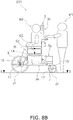
- a modification will describe a configuration that the caregiver M1 is capable of riding on the electric wheelchair 1, 101 while seated on a seat portion 3g.
- the vehicle body 3 of an electric wheelchair 201 further includes the seat portion 3g (exemplary support portion) capable of supporting the caregiver M1.
- the seat portion 3g exemplary support portion
- the seat portion 3g is attached to the second frame portion 3b so as to be detachable therefrom.
- the seat portion 3g is attached to the second frame portion 3b in the condition that the first frame portion 3a is disposed in the first position.
- the seat portion 3g is detached from the second frame portion 3b in the condition that the first frame portion 3a is disposed in the second position.
- the caregiver M1 is enabled to be seated on the seat portion 3g in the condition that the first frame portion 3a is disposed in the first position while the seat portion 3g is attached to the second frame portion 3b.
- both the caregiver M1 and the care receiver M2 are enabled to ride on the vehicle body 3, and the caregiver M1 is capable of operating the electric wheelchair 201.
- the seat portion 3g is stored by the vehicle body 3 in the condition that the first frame portion 3a is disposed in the second position while the seat portion 3g is detached from the second frame portion 3b. Part of the seat portion 3g is herein stored in the first frame portion 3a. The rest of the seat portion 3g is disposed on the second frame portion 3b.
- the care receiver M2 is enabled to ride on the vehicle body 3, whereas the caregiver M1 is disabled to ride on the vehicle body 3.
- the caregiver M1 is herein capable of operating the electric wheelchair 201 in the condition that only the care receiver M2 rides on the vehicle body 3.
- the seat portion 3g is stored in the first frame portion 3a, but alternatively, as with an electric wheelchair 301 shown in FIG. 9 , the seat portion 3g can be folded while attached to the second frame portion 3b. When the seat portion 3g is thus folded, the first frame portion 3a can be disposed in the second position.
- Each of the first and second preferred embodiments described above has exemplified the configuration that the number of front wheels 5 is two and the number of rear wheels 7 is one.
- the number of front wheels 5 and the number of rear wheels 7 can be arbitrarily set as long as the total number of front and rear wheels 5 and 7 is plural.
- Each of the first and second preferred embodiments described above has exemplified the configuration that the front wheels 5 and the rear wheel 7 are vehicle wheels.
- the front wheels 5 and the rear wheel 7 can be made in the form of at least any one of vehicle wheels, ball casters, crawlers and omni wheels.
- each or both of the first and second rotational axes J1 and J2 is/are defined by the center/centers of a ball/balls composing the ball caster/casters.
- each or both of the first and second rotational axes J1 and J2 is/are defined by the rotational center/centers of relevant one/two of a plurality of rotors composing each crawler.
- each or both of the first and second rotational axes J1 and J2 is/are defined by the center/centers of gravity in the omni wheel/wheels.
- Each of the first and second preferred embodiments described above has exemplified the configuration that the electric wheelchair 1, 101 includes the front wheels 5 and the rear wheel 7. However, at least one intermediate wheel can be further disposed between the front wheels 5 and the rear wheel 7. In this case, the number of intermediate wheels can be arbitrarily set as long as one or more intermediate wheels are provided.
- each of the first and second preferred embodiments described above has exemplified the configuration that the operating device 13 is composed of such a lever member as a joystick.
- the operating device 13 can be a contact input device including a touch screen.
- Each of the first and second preferred embodiments described above has exemplified the configuration that the second rotational axis J2 is displaced (set off) from the intersecting axis K1 as seen in a side view.
- the amount of displacement (offset) between the second rotational axis J2 and the intersecting axis K1 can be zero. In this case, for instance, when the motors 12 drive the front wheels 5 as with the first preferred embodiment, it is preferable to steer the rear wheel 7 by the steering device 18 described in the second preferred embodiment.
Landscapes
- Health & Medical Sciences (AREA)
- Life Sciences & Earth Sciences (AREA)
- Animal Behavior & Ethology (AREA)
- General Health & Medical Sciences (AREA)
- Public Health (AREA)
- Veterinary Medicine (AREA)
- Engineering & Computer Science (AREA)
- Chemical & Material Sciences (AREA)
- Combustion & Propulsion (AREA)
- Transportation (AREA)
- Mechanical Engineering (AREA)
- Electric Propulsion And Braking For Vehicles (AREA)
Description
- The present invention relates to an electric wheel chair, particularly to an electric wheel chair that enables a caregiver to ride thereon and is capable of being actuated by a prime mover.
-
WO 2017/143454 A1 discloses a manual wheelchair having an upper frame in form of a seat portion enabling a user to ride on and a lower frame with drive wheels and guiding wheels, wherein the seat portion can be tilted relative to the lower frame around a horizontal central axis coincident with the rotation axis of the drive wheels. This enables that the pivot center of the seat portion is coincident at any moment and any position with the rotation axis of the drive wheel allowing to maintain a constant distance between a user's and each pushrim of each drive wheel. Thus, it is easier for the user to push the drive wheels in any tilted position. A type of well-known electric wheelchairs proposed so far enables a caregiver and a care receiver to ride thereon (see Japan Laid-open Patent Application Publications Nos.2004-188076 2005-176980 US 7 971 893 B1 discloses also an electric wheel chair with a standing platform for a care giver. - In the well-known electric wheelchairs, the riding portion for the caregiver is provided as an additional component to the vehicle body. This leaves concern that increase in size of the well-known electric wheelchairs is inevitable. Moreover, in the well-known electric wheelchairs, change in balance of the center of gravity occurs between a condition that the caregiver rides on the riding portion and a condition that the caregiver gets off the riding portion. Hence, it is difficult to stably actuate the well-known electric wheelchairs.
- The present invention is made in view of the aforementioned drawbacks. It is an object of the present invention to provide an electric wheelchair realized in compact size. Besides, it is another object of the present invention to provide an electric wheelchair capable of being stably actuated.
- These objects are achieved by an electric wheelchair according to
claim 1. Advantageous embodiments of the invention are subject-matter of the dependent claims. - A moving device in the form of an electric wheelchair according to an aspect of the present invention is an electric wheelchair that is enabled to be actuated by a prime mover including a motor and enables a caregiver to ride thereon. The moving device includes a vehicle body and a plurality of rotors (a plurality of rolling elements). The vehicle body includes a first frame portion and a second frame portion. The second frame portion enables the caregiver to ride thereon. The first frame portion enables a care receiver taken care of by the caregiver to ride thereon. The plurality of rotors are provided on the second frame portion, and are rotatable in movement of the vehicle body. Here, a wheel base defined by a distance between axes of the plurality of rotors is constant. The first frame portion is provided on the second frame portion so as to be movable in accordance with a motion of the caregiver riding on and getting off the first frame portion. The first frame portion is movable between a first position and a second position with respect to the second frame portion. The first position enables both the caregiver and the care receiver to ride on the vehicle body. The second position enables only the care receiver to ride on the vehicle body.
- The present electric wheelchair enables both the caregiver and the care receiver to ride thereon or enables only the care receiver to ride thereon by moving the first frame portion with respect to the second frame portion. Thus, the present electric wheelchair is not required to be provided with a riding portion for the caregiver as an additional portion. Hence, the present electric wheelchair can be realized in compact size. Moreover, the present electric wheelchair enables not only the care receiver but also the caregiver to ride thereon only by moving the first frame portion with respect to the second frame portion. This makes it possible to stably actuate the electric wheelchair.
- In an electric wheelchair according to another aspect of the present invention, the vehicle body preferably further includes a support portion. The support portion is capable of supporting the caregiver and is provided on the second frame portion. With this configuration, the electric wheelchair can be stably actuated.
- In an electric wheelchair according to another aspect of the present invention, the support portion is preferably attached to an upper part of the second frame portion so as to be detachable therefrom. In this case, the support portion is detached from and storable in the vehicle body when the caregiver gets off the vehicle body. With this configuration, the moving device can be realized in compact size.
- In an electric wheelchair according to another aspect of the present invention, the support portion is preferably foldable when the caregiver gets off the vehicle body. With this configuration, the electric wheelchair can be realized in compact size.
- In an electric wheelchair according to another aspect of the present invention, the vehicle body preferably further includes a restriction portion. The restriction portion restricts the first frame portion from moving with respect to the second frame portion. With this configuration, the electric wheelchair can be stably actuated in both situations when both the caregiver and the care receiver ride thereon and when only the care receiver rides thereon.
- In an electric wheelchair according to another aspect of the present invention, the plurality of rotors are preferably formed by at least three rotors. With this configuration, the electric wheelchair can be stably actuated.
- In the electric wheelchair according to the present invention, the plurality of rotors include a first rotor and a second rotor. The first rotor is provided on the second frame portion so as to be rotatable about a first rotational axis. The second rotor is provided on the second frame portion so as to be rotatable about a second rotational axis disposed at a predetermined interval from the first rotational axis. The prime mover drives at least one of the first rotor and the second rotor. With this configuration, the electric wheelchair can be preferably and suitable actuated.
- In an electric wheelchair according to another aspect of the present invention, the vehicle body is preferably configured such that a center of gravity of the caregiver and a center of gravity of the care receiver are disposed within the wheel base when the caregiver and the care receiver ride on the vehicle body. With this configuration, the electric wheelchair can be stably actuated.
- An electric wheelchair according to another aspect of the present invention preferably further includes a control device capable of controlling at least one of the plurality of rotors. With this configuration, the electric wheelchair can be stably actuated.
- An electric wheelchair according to another aspect of the present invention preferably further includes a first sensor. The first sensor is provided for detecting an object related to derailing of at least one of the plurality of rotors. The control device herein includes a first controller. The first controller controls the at least one of the plurality of rotors so as to avoid the derailing when the first sensor detects the object related to the derailing. With this configuration, the electric wheelchair can be more stably actuated.
- An electric wheelchair according to another aspect of the present invention preferably further includes a second sensor. The second sensor is provided for detecting an object related to contact of the vehicle body. The control device herein includes a second controller. The second controller controls the at least one of the plurality of rotors so as to avoid the contact when the second sensor detects the obj ect related to the contact. With this configuration, the electric wheelchair can be more stably actuated.
- An electric wheelchair according to another aspect of the present invention preferably further includes a third sensor. The third sensor is provided for detecting a position of the caregiver with respect to the vehicle body. The control device herein includes a third controller. The third controller stops the prime mover when a distance between the caregiver and the vehicle body becomes greater than or equal to a predetermined distance. In this case, the prime mover is stopped when the caregiver separates from the vehicle body at the predetermined distance or greater. With this configuration, security of the electric wheelchair can be reliably ensured.
- An electric wheelchair according to another aspect of the present invention preferably further includes a switch portion for operating turning on and off the prime mover. With this configuration, safety of the electric wheelchair can be reliably ensured.
- Overall, according to the present invention, an electric wheelchair can be realized in compact size and can be stably actuated.
-
-
FIG. 1 is a front view of an electric wheelchair employing a first preferred embodiment of the present invention. -
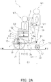
FIG. 2A is a side view of the electric wheelchair employing the first preferred embodiment of the present invention. -
FIG. 2B is a side view of the electric wheelchair employing the first preferred embodiment of the present invention. -
FIG. 3 is a functional block diagram of the electric wheelchair employing the first preferred embodiment of the present invention. -
FIG. 4 is a diagram for explaining control performed in movement (turn) of the electric wheelchair employing the first preferred embodiment of the present invention. -
FIG. 5 is a diagram for explaining control performed in movement (neutral turn) of the electric wheelchair employing the first preferred embodiment of the present invention. -
FIG. 6A is a side view of an electric wheelchair employing a second preferred embodiment of the present invention. -
FIG. 6B is a side view of the electric wheelchair employing the second preferred embodiment of the present invention. -
FIG. 7 is a functional block diagram of the electric wheelchair employing the second preferred embodiment of the present invention. -
FIG. 8A is a side view of an electric wheelchair exemplified as a modification of the first and second preferred embodiments of the present invention. -
FIG. 8B is a side view of the electric wheelchair exemplified as the modification of the first and second preferred embodiments of the present invention. -
FIG. 9 is a side view of an electric wheelchair exemplified as another modification of the first and second preferred embodiment of the present invention. - As shown in
FIG. 1 , an electric wheelchair 1 (exemplary moving device), employing a preferred embodiment of the present invention, is configured to enable a caregiver M1 to get thereon and is also configured to be capable of being actuated by aprime mover 11. Additionally, theelectric wheelchair 1 is configured to be movable forward and backward. Furthermore, theelectric wheelchair 1 is configured to be changeable in traveling direction and speed by an operating device 13 (to be described). - As shown in
FIGS. 1 ,2A and2B , theelectric wheelchair 1 includes avehicle body 3, a pair of front wheels 5 (exemplary first rotor) and a rear wheel 7 (exemplary second rotor). It should be noted that thefront wheels 5 and therear wheel 7 are exemplary plural rotors, and are preferably composed of at least three rotors. - Additionally, the
electric wheelchair 1 further includes the prime mover 11 (exemplary prime mover). Moreover, theelectric wheelchair 1 further includes the operatingdevice 13. Furthermore, theelectric wheelchair 1 further includes aswitch portion 16. - Besides, the
electric wheelchair 1 further includes at least one vehiclespeed detection sensor 14. Moreover, theelectric wheelchair 1 includes at least one object sensor 15 (exemplary second sensor), at least one step sensor 17 (exemplary first sensor) and a position recognition sensor 19 (exemplary third sensor). Furthermore, theelectric wheelchair 1 further includes acontrol device 21. - As shown in
FIGS. 1 ,2A and2B , thevehicle body 3 is configured to enable a care receiver M2 and the caregiver M1 who takes care of the care receiver M2 to ride thereon. The posture of thevehicle body 3 is changeable between a first posture and a second posture. The first posture enables both the caregiver M1 and the care receiver M2 to ride on thevehicle body 3. The second posture enables only the care receiver M2 to ride on thevehicle body 3. - A wheel base C1 of the
vehicle body 3 is constant. In other words, the wheel base C1 of thevehicle body 3 is set to a predetermined length. The wheel base C1 is defined as an interval between a first rotational axis J1 of thefront wheels 5 and a second rotational axis J2 of therear wheel 7. - The
vehicle body 3 is configured to locate both a center of gravity G1 of the caregiver M1 and a center of gravity G2 of the care receiver M2 within the wheel base C1 when the caregiver M1 and the care receiver M2 ride on the vehicle body 3 (seeFIG. 2A ). - Specifically, the
vehicle body 3 is configured to locate a point of action S1 within the wheel base C1. The point of action S1 is a point at which the mass of the caregiver M1 acts on thevehicle body 3 in the vertical direction. Thevehicle body 3 is also configured to locate a point of action S2 within the wheel base C1. The point of action S2 is a point at which the mass of the care receiver M2 acts on thevehicle body 3 in the vertical direction. It should be noted that the points of actions S1 and S2 can be interpreted as points at which straight lines, extending from the centers of gravity G1 and G2 in the vertical direction, intersect with a plane arranged in parallel to a traveling surface S in a range between the first rotational axis J1 and the second rotational axis J2. - The vehicle body configuration will be hereinafter explained. As shown in
FIGS. 1 ,2A and2B , thevehicle body 3 includes afirst frame portion 3a (exemplary second frame portion in appended claims) and asecond frame portion 3b (exemplary first frame portion in appended claims). Thevehicle body 3 further includes alock portion 3f (exemplary restriction portion). - As shown in
FIGS. 1 ,2A and2B , thefirst frame portion 3a is configured to enable the care receiver M2 who is taken care of by the caregiver M1 to ride thereon. Thefirst frame portion 3a is provided with aseat portion 3c enabling the care receiver M2 to be seated thereon. - The
first frame portion 3a is provided on thesecond frame portion 3b so as to be movable in accordance with the motion of the caregiver M1 riding on and getting off thesecond frame portion 3b. - The
first frame portion 3a is movable between a first position (seeFIG. 2A ) and a second position (seeFIG. 2B ) with respect to thesecond frame portion 3b. The first position enables both the caregiver M1 and the care receiver M2 to ride on thevehicle body 3. The second position enables only the care receiver M2 to ride on thevehicle body 3. When thefirst frame portion 3a is disposed in the first position, thevehicle body 3 takes the first posture described above. When thefirst frame portion 3a is disposed in the second position, thevehicle body 3 takes the second posture described above. - For example, at least one rolling element (e.g., a plurality of rollers 4) is attached to either the
first frame portion 3a or thesecond frame portion 3b. In the present preferred embodiment, theplural rollers 4 are attached to thefirst frame portion 3a. Theplural rollers 4 roll on thesecond frame portion 3b, whereby thefirst frame portion 3a becomes movable between the first and second positions described above with respect to thesecond frame portion 3b. - The present preferred embodiment has exemplified the configuration that the
first frame portion 3a is moved with respect to thesecond frame portion 3b through theplural rollers 4. It should be noted, however, that thefirst frame portion 3a can be directly moved with respect to thesecond frame portion 3b without using such rolling elements as therollers 4 so long as thefirst frame portion 3a is movable with respect to thesecond frame portion 3b. - Now, as shown in
FIG. 2A , when thefirst frame portion 3a is disposed in the first position and the caregiver M1 and the care receiver M2 ride on thesecond frame portion 3b (ariding portion 3d) and thefirst frame portion 3a (theseat portion 3c), respectively, the center of gravity G1 (the point of action S1) of the caregiver M1 and the center of gravity G2 (the point of action S2) of the care receiver M2 are located within the wheel base C1. Specifically in this case, a center of gravity G0 (a point of action S0) of the caregiver M1 and the care receiver M2 is located in substantially the middle of the wheel base C1. - By contrast, as shown in
FIG. 2B , when thefirst frame portion 3a is disposed in the second position and only the care receiver M2 rides on thefirst frame portion 3a (theseat portion 3c), the center of gravity G2 (the point of action S2) of the care receiver M2 is located within the wheel base C1. Specifically in this case, the center of gravity G2 (the point of action S2) of the care receiver M2 is located in substantially the middle of the wheel base C1. - As shown in
FIGS. 1 ,2A and2B , thesecond frame portion 3b is configured to enable the caregiver M1 to ride thereon. Thesecond frame portion 3b is provided with the ridingportion 3d that enables the caregiver M1 to ride thereon. - The riding
portion 3d is provided on thesecond frame portion 3b so as to be disposed between the pair offront wheels 5 and therear wheel 7. Detailedly, when thefirst frame portion 3a is disposed in the second position, the ridingportion 3d is provided on thesecond frame portion 3b so as to be disposed between thefirst frame portion 3a and the rear wheel 7 (the second rotational axis J2). - The
lock portion 3f restricts thefirst frame portion 3a from moving with respect to thesecond frame portion 3b. Detailedly, thelock portion 3f restricts thefirst frame portion 3a from moving with respect to thesecond frame portion 3b in the first position and the second position. In other words, the posture of thevehicle body 3 is kept in either the first posture or the second posture by thelock portion 3f. - The
lock portion 3f is provided between thefirst frame portion 3a and thesecond frame portion 3b. For example, thelock portion 3f is a member elongated in one direction. Thelock portion 3f is pivotably attached at one end thereof to one of the first andsecond frame portions lock portion 3f is configured to be capable of being engaged at the other end thereof with the other of the first andsecond frame portions - In the present preferred embodiment, the
lock portion 3f is pivotably attached at one end thereof to thefirst frame portion 3a through a coupling member such as a pin member. Thelock portion 3f is configured to be capable of being engaged at the other end thereof with thesecond frame portion 3b. Thelock portion 3f herein includes an engaging portion (not shown in the drawings) in the other end thereof, whereas thesecond frame portion 3b includes an engaged portion (not shown in the drawings). The engaging portion and the engaged portion can be arbitrarily configured as long as the both portions are capable of restricting thefirst frame portion 3a from moving with respect to thesecond frame portion 3b. - When the
lock portion 3f is herein disengaged, thefirst frame portion 3a becomes movable with respect to thesecond frame portion 3b as described above. In other words, when thelock portion 3f is disengaged, the posture of thevehicle body 3 becomes changeable between the first posture and the second posture. - As shown in
FIGS. 1 ,2A and2B , the pair offront wheels 5 is, for instance, vehicle wheels. The pair offront wheels 5 is provided on thevehicle body 3 so as to be rotatable in movement of thevehicle body 3. Each of the pair offront wheels 5 is herein rotatably attached to thesecond frame portion 3b. The pair offront wheels 5 makes contact with the ground while being attached to thesecond frame portion 3b. - Each of the pair of
front wheels 5 has the first rotational axis J1. The pair offront wheels 5 is disposed in opposition in the extending direction of the first rotational axis J1 (seeFIG. 1 ). The pair offront wheels 5 is provided on the vehicle body 3 (e.g., thesecond frame portion 3b) so as to be rotatable about the first rotational axis J1. Detailedly, the pair offront wheels 5 is provided on thesecond frame portion 3b through a shaft portion so as to be rotatable about the first rotational axis J1. In this condition, the pair offront wheels 5 is rotatable while in contact with the traveling surface S. - As shown in
FIGS. 1 ,2A and2B , therear wheel 7 is, for instance, a vehicle wheel. Therear wheel 7 is attached to the vehicle body 3 (e.g., thesecond frame portion 3b). Therear wheel 7 is herein disposed at an interval from the pair offront wheels 5. Therear wheel 7 is attached to thesecond frame portion 3b so as to be rotatable about the second rotational axis J2. - The
rear wheel 7 includes the second rotational axis J2. The second rotational axis J2 is disposed at an interval from the first rotational axis J1. The second rotational axis J2 is herein disposed at an interval from the first rotational axis J1 in an orthogonal direction orthogonal to the first rotational axis J1. The orthogonal direction is arranged substantially in parallel to the traveling surface S. Therear wheel 7 is provided on the vehicle body 3 (e.g., thesecond frame portion 3b) so as to be rotatable about the second rotational axis J2. Detailedly, therear wheel 7 is attached to thesecond frame portion 3b through a shaft portion so as to be rotatable about the second rotational axis J2. In this condition, therear wheel 7 is rotatable while in contact with the traveling surface S. - Additionally, as shown in
FIGS. 2A and2B , therear wheel 7 is attached to thesecond frame portion 3b so as to be turnable about an intersecting axis K1 intersecting with the second rotational axis J2. Detailedly, awheel holding portion 3e is attached to thesecond frame portion 3b so as to be turnable about the intersecting axis K1. Additionally, thewheel holding portion 3e supports therear wheel 7 so as to make therear wheel 7 rotatable about the second rotational axis J2. In other words, therear wheel 7 is attached to thesecond frame portion 3b so as to be rotatable about the second rotational axis J2 with respect to thewheel holding portion 3e and be turnable about the intersecting axis K1 with respect to thesecond frame portion 3b. - The wheel base C1 herein corresponds to the interval between the first rotational axis J1 of the
front wheels 5 and the second rotational axis J2 of therear wheel 7 in a condition that the first rotational axis J1 and the second rotational axis J2 are substantially in parallel to each other. - The
prime mover 11 drives at least one of the pair offront wheels 5 and therear wheel 7. Theprime mover 11 herein drives the pair offront wheels 5. Theprime mover 11 is composed of, for instance, a pair ofmotors 12. - As shown in
FIGS. 1 ,2A and2B , the pair ofmotors 12 drives the pair offront wheels 5 on a one-to-one basis. Each of the pair ofmotors 12 is attached to the vehicle body 3 (e.g., thesecond frame portion 3b). Each of the pair ofmotors 12 receives electric supply from a power source (not shown in the drawings) and is thereby actuated. It should be noted that the power source is attached to the vehicle body 3 (e.g., thefirst frame portion 3a). - The
front wheels 5 are driven independently from each other by actuation of therespective motors 12. In other words, in the present preferred embodiment, theelectric wheelchair 1 employs front wheel drive. With the configuration of thefront wheels 5 driven independently from each other by therespective motors 12, the traveling direction of theelectric wheelchair 1 is herein determined by difference in rotational speed between thefront wheels 5. Additionally, turn and neutral turn are performed by difference in rotational speed between thefront wheels 5. - It should be noted that in the example herein described, the pair of
front wheels 5 is driven independently from each other by the pair ofmotors 12, but alternatively, the pair offront wheels 5 can be driven by onemotor 12. In this case, for instance, it is preferable that a differential gear is disposed between themotor 12 and the pair offront wheels 5. Additionally, it is preferable that a steering device 18 (seeFIGS. 6A and6B ) for steering therear wheel 7 is attached to the vehicle body 3 (e.g., thesecond frame portion 3b) whereby the traveling direction of theelectric wheelchair 1 is determined by therear wheel 7. Because of the above, the pair offront wheels 5 can be preferably and suitably driven by even onemotor 12. - The operating
device 13 is used for maneuvering theelectric wheelchair 1. As shown inFIGS. 2A and2B , the operatingdevice 13 is composed of, for instance, such a lever member as a joystick. The operatingdevice 13 is provided on the vehicle body 3 (e.g., thesecond frame portion 3b). The operatingdevice 13 is herein attached to the rear part of thesecond frame portion 3b. When the operatingdevice 13 is operated by the caregiver M1, a signal corresponding to operating the operatingdevice 13 is transmitted to thecontrol device 21. - It should be noted that in the example herein described, the operating
device 13 is operated by the caregiver M1, but alternatively, an operating device (not shown in the drawings) operable by the care receiver M2 can be provided on the vehicle body 3 (e.g., thefirst frame portion 3a) as an operating device intended for the care receiver M2 aside from the operatingdevice 13 intended for the caregiver M1. - The
switch portion 16 is provided for operating turning on and off theprime mover 11. As shown inFIGS. 2A and2B , theswitch portion 16 is attached to the vehicle body 3 (e.g., thefirst frame portion 3a). Theswitch portion 16 is, for instance, a button switch. When theswitch portion 16 is being turned on, theprime mover 11 receives electric supply from the power source and actuation thereof is enabled. When theswitch portion 16 is being turned off, theprime mover 11 is blocked from receiving electric supply from the power source and actuation thereof is disabled. - A plurality of (e.g., two) vehicle
speed detection sensors 14 are provided for detecting the vehicle speed. As shown inFIG. 1 , the plural vehiclespeed detection sensors 14 are attached to thevehicle body 3. The vehiclespeed detection sensors 14 are herein attached to thefirst frame portion 3a so as to be opposed to thefront wheels 5, respectively. Each vehiclespeed detection sensor 14 receives electric supply from the power source and is thereby actuated. Each vehiclespeed detection sensor 14 detects the rotational speed or angular velocity of eachfront wheel 5. A signal, corresponding to the rotational speed or angular velocity of eachfront wheel 5 is transmitted to thecontrol device 21. - As shown in
FIGS. 1 ,2A and2B , a plurality of (e.g., four)object sensors 15 are provided for detecting an object related to contact with thevehicle body 3. Detailedly, theobject sensors 15 are provided for detecting collision against a moving object and/or a stationary object. Theplural object sensors 15 are attached to thevehicle body 3. - Two of the
object sensors 15 are herein attached to the both sides of the pair offront wheels 5, for instance, the both ends of the shaft portion by which thefront wheels 5 are rotatably supported, respectively. Furthermore, other two of theobject sensors 15 are attached to the both ends of therear wheel 7, for instance, the both ends of the shaft portion by which therear wheel 7 is rotatably supported, respectively. - Each
object sensor 15 receives electric supply from the power source and is thereby actuated. Eachobject sensor 15 detects the distance to a moving object and/or a stationary object. A signal corresponding to the distance to the moving object and/or the stationary object is transmitted to thecontrol device 21. - As shown in
FIGS. 1 ,2A and2B , a plurality of (e.g., four)step sensors 17 are provided for detecting an object related to derailing of at least one of thefront wheels 5 and therear wheel 7. Theplural step sensors 17 are attached to thevehicle body 3. - Two of the
step sensors 17 are herein attached to the both sides of the pair offront wheels 5, for instance, the both ends of the shaft portion by which thefront wheels 5 are rotatably supported, respectively. Furthermore, other two of thestep sensors 17 are attached to the both sides of therear wheel 7, for instance, the both ends of the shaft portion by which therear wheel 7 is rotatably supported, respectively. - Each
step sensor 17 receives electric supply from the power source and is thereby actuated. Eachstep sensor 17 detects information of the traveling surface S (e.g., the ground) located laterally to thefront wheel 5 relevant thereto or information of the traveling surface S (e.g., the ground) located laterally to therear wheel 7. A signal for identifying the information of the traveling surface S is transmitted to thecontrol device 21. - The
position recognition sensor 19 is provided for detecting the position of the caregiver M1 with respect to thevehicle body 3. Theposition recognition sensor 19 is attached to thevehicle body 3. - The
position recognition sensor 19 is herein attached to thefirst frame portion 3a. Theposition recognition sensor 19 detects the position of the caregiver M1, for instance, the distance between the caregiver M1 and thefirst frame portion 3a. Theposition recognition sensor 19 receives electric supply from the power source and is thereby actuated. A signal corresponding to the distance between the caregiver M1 and thefirst frame portion 3a is transmitted to thecontrol device 21. - As shown in
FIGS. 2A and2B , thecontrol device 21 is attached to the vehicle body 3 (e.g., thefirst frame portion 3a). Thecontrol device 21 is configured to be capable of controlling at least one of the pair offront wheels 5 and therear wheel 7. Thecontrol device 21 is herein configured to be capable of controlling the pair offront wheels 5. - The
control device 21 receives signals from the operatingdevice 13, the vehiclespeed detection sensors 14, theobject sensors 15, thestep sensors 17 and theposition recognition sensor 19, respectively, and supplies driving electricity to the pair ofmotors 12. In response, therespective motors 12 are actuated based on the driving electricity, and the pair offront wheels 5 is driven by themotors 12, respectively. - As shown in
FIG. 3 , thecontrol device 21 includes adrive controller 23, avehicle speed controller 27, a collision avoidance controller 29 (exemplary second controller), a derailing avoidance controller 31 (exemplary first controller) and a motor stopper 32 (exemplary third controller). - The
drive controller 23 shown inFIG. 3 controls the pair ofmotors 12 based on the signal transmitted thereto from the operatingdevice 13. For example, when the operatingdevice 13 is tilted forward or obliquely forward by the caregiver M1, each of the pair ofmotors 12 is controlled by thedrive controller 23 so as to forwardly move theelectric wheelchair 1. On the other hand, when the operatingdevice 13 is tilted backward or obliquely backward by the caregiver M1, each of the pair ofmotors 12 is controlled by thedrive controller 23 so as to backwardly move theelectric wheelchair 1. - Yet on the other hand, when the operating
device 13 is tilted sideward by the caregiver M1, each of the pair ofmotors 12 is controlled by thedrive controller 23 such that theelectric wheelchair 1 performs neutral turn. - Thus, each of the pair of
motors 12 is controlled by thedrive controller 23 in response to the direction that the operatingdevice 13 is operated. Additionally, the pair offront wheels 5 is driven by the pair ofmotors 12 on a one-to-one basis. - When the operating
device 13 is herein tilted obliquely forward by the caregiver M1 as described above, theelectric wheelchair 1 is moved in either a right front direction or a left front direction. In this case, as shown inFIG. 4 , thedrive controller 23 controls the rotational speed of each of the pair ofmotors 12 such that a maximum trail L1 of the pair offront wheels 5 about a predetermined point O1 becomes greater than a maximum trail L2 of therear wheel 7 about the predetermined point O1. - For example, when the
electric wheelchair 1 turns left on an L-shaped road S (seeFIG. 4 ), thedrive controller 23 controls the rotational speed of each of the pair ofmotors 12 such that a first turn radius R1 of the outer one of the pair offront wheels 5 about a first turn center O1 becomes greater than a second turn radius R2 of therear wheel 7 about the first turn center O1. Thus, the rotational speed of each of the pair ofmotors 12 is controlled by thedrive controller 23, whereby the rotational speed of each of the pair offront wheels 5 is controlled. - In this case, the
drive controller 23 sets a difference in rotational speed between the rotational speed of onemotor 12 driving the outer-side front wheel 5 and that of theother motor 12 driving the inner-side front wheel 5 such that the first turn radius R1 becomes greater than the second turn radius R2. In other words, thedrive controller 23 sets the difference in rotational speed between the rotational speed of the outer-side front wheel 5 and that of the inner-side front wheel 5 through therespective motors 12. Accordingly, therear wheel 7 is prevented from moving outside the trail of the outer-side front wheel 5 with reference to the first turn center O1. Hence, theelectric wheelchair 1 is preferably and suitably enabled to travel in such a situation as a narrow traveling road. - It should be noted that when the operating
device 13 is tilted obliquely backward, thedrive controller 23 similarly sets the rotational speed of each of the pair ofmotors 12 so as to control the rotational speed of each of the pair offront wheels 5 such that a maximum trail L1 (R1) of the pair offront wheels 5 about the first turn center O1 becomes greater than a maximum trail L2 (R2) of therear wheel 7 about the first turn center O1. - On the other hand, when the operating
device 13 is tilted sideward by the caregiver M1 as described above, theelectric wheelchair 1 performs neutral turn as shown inFIG. 5 . In this case, thedrive controller 23 controls the rotational speed of each of the pair ofmotors 12 such that a trail L3 of onefront wheel 5 about a predetermined point O2 and that of the otherfront wheel 5 about the predetermined point O2 overlap with each other. Thus, the rotational speed of each of the pair ofmotors 12 is controlled by thedrive controller 23, whereby the rotational speed of each of the pair offront wheels 5 is controlled. - For example, as shown in
FIG. 5 , when theelectric wheelchair 1 performs neutral turn, thedrive controller 23 controls the pair offront wheels 5 such that the outer-side one and the inner-side one of the pair offront wheels 5 are turned about a second turn center O2 while being rotated in opposite directions at an equal rotational speed. Accordingly, the pair offront wheels 5 and therear wheel 7 form the circular trails L3 and L4, respectively, about the second turn center O2, whereby the direction of theelectric wheelchair 1 can be preferably and suitably changed. - The
vehicle speed controller 27 shown inFIG. 3 controls the pair ofmotors 12 based on the signals transmitted thereto from the vehiclespeed detection sensors 14. For example, thevehicle speed controller 27 calculates the rotational speeds of thefront wheels 5 based on those detected by the vehiclespeed detection sensors 14, respectively. It should be noted that time information used in calculating the rotational speeds can be obtained from the vehiclespeed detection sensors 14, or alternatively, can be measured in thevehicle speed controller 27. - Then, the
vehicle speed controller 27 determines whether or not the rotational speeds are less than a predetermined speed. When the rotational speeds are greater than or equal to the predetermined speed, thevehicle speed controller 27 issues a command to the pair ofmotors 12 so as to cause the pair ofmotors 12 to regulate the rotational speeds less than the predetermined speed. Accordingly, the vehicle speed of theelectric wheelchair 1 can be restricted from getting too high. - When at least one of the
plural object sensors 15 detects an object related to collision, thecollision avoidance controller 29 shown inFIG. 3 controls at least one of thefront wheels 5 and therear wheel 7 so as to avoid the collision. Detailedly, when at least one of theplural object sensors 15 detects an object related to collision, thecollision avoidance controller 29 controls the pair ofmotors 12 so as to avoid the collision. - For example, the
collision avoidance controller 29 calculates objective distances/distance from thevehicle body 3 to a moving object and/or a stationary object based on the signals from therespective object sensors 15. Then, thecollision avoidance controller 29 determines wither or not each of the objective distance/distances is less than a predetermined distance. When at least one of the objective distance/distances is less than the predetermined distance, thecollision avoidance controller 29 issues a command to the pair ofmotors 12 so as to cause the pair ofmotors 12 to stop rotation of the pair offront wheels 5. Accordingly, theelectric wheelchair 1 can be restricted from colliding with the moving object and/or the stationary object. - When at least one of the
step sensors 17 detects an object related to derailing, the derailingavoidance controller 31 shown inFIG. 3 controls at least one of thefront wheels 5 and therear wheel 7 so as to avoid the derailing. Detailedly, when at least one of thestep sensors 17 detects an object related to derailing, the derailingavoidance controller 31 controls the pair ofmotors 12 so as to avoid the derailing. - For example, the derailing
avoidance controller 31 recognizes information of the traveling surface S in the traveling direction of thevehicle body 3 based on the signals from therespective step sensors 17. Then, the derailingavoidance controller 31 determines whether or not the step of the traveling surface S has a predetermined height or greater. When it is herein determined that the step of the traveling surface S has the predetermined height or greater, the derailingavoidance controller 31 issues a command to the pair ofmotors 12 so as to cause the pair ofmotors 12 to stop rotation of the pair offront wheels 5. Accordingly, it is possible to avoid a situation that theelectric wheelchair 1 derails due to the step or collides with the step. - It should be noted that when the height of the step on the traveling surface S is less than the predetermined height, the derailing
avoidance controller 31 does not issue the command to the pair ofmotors 12 so as to cause the pair ofmotors 12 to stop rotation of the pair offront wheels 5. Accordingly, traveling of theelectric wheelchair 1 is continued. - The
motor stopper 32 stops actuation of the pair ofmotors 12 based on the signal transmitted thereto from theposition recognition sensor 19. - For example, the
motor stopper 32 determines whether or not the distance between the caregiver M1 and thevehicle body 3 becomes greater than or equal to a predetermined distance based on the signal transmitted thereto from theposition recognition sensor 19. When it is herein determined that the distance between the caregiver M1 and thevehicle body 3 becomes greater than or equal to the predetermined distance, themotor stopper 32 issues a command to the pair ofmotors 12 so as to cause the pair ofmotors 12 to stop rotation of the pair offront wheels 5. Accordingly, even if the caregiver M1 forgets to turn off theswitch portion 16 and separates from theelectric wheelchair 1 while theswitch portion 16 is being turned on, it is possible to avoid a situation that theelectric wheelchair 1 is actuated against the intention of the caregiver M1. - It should be noted that as described above, when the vehicle body 3 (e.g., the
first frame portion 3a) is provided with the operating device intended for the care receiver M2 (not shown in the drawings) operable by the care receiver M2, thecontrol device 21 similarly executes, as does in response to operating the operatingdevice 13 for the caregiver M1, the aforementioned control in response to operating the operating device intended for the care receiver M2. - The first preferred embodiment has exemplified the configuration of the
electric wheelchair 1 employing front wheel drive. However, anelectric wheelchair 101 according to a second preferred embodiment employs rear wheel drive. In this regard, the second preferred embodiment is different from the first preferred embodiment. Therefore, in the second preferred embodiment, only constituent elements, which are different from comparative ones in the first preferred embodiment, will be explained without explaining constituent elements that are substantially the same as comparative ones in the first preferred embodiment. It should be noted that when a given constituent element in the second preferred embodiment is the same as comparative one in the first preferred embodiment, a reference sign assigned to the comparative one will be assigned to the given constituent element. - In the second preferred embodiment, as shown in
FIGS. 6A and6B , the prime mover 11 (e.g., the motor 12) drives therear wheel 7. Themotor 12 is attached to the vehicle body 3 (e.g., a rear part of thesecond frame portion 3b) and is connected to therear wheel 7. Theelectric wheelchair 101 according to the second preferred embodiment employs rear wheel drive. Hence, the pair offront wheels 5 is rotatably attached to thesecond frame portion 3b without being driven by themotors 12. - Additionally, the
electric wheelchair 101 further includes thesteering device 18. Besides as shown inFIG. 7 , thecontrol device 21 further includes adirection controller 25. - The
steering device 18 is provided for setting the steering angle of therear wheel 7. As shown inFIGS. 6A and6B , thesteering device 18 sets the steering angle of therear wheel 7 by turning therear wheel 7 about the intersecting axis K1 described above. In other words, when thesteering device 18 sets the steering angle of therear wheel 7, the traveling direction of theelectric wheelchair 101 is determined. - The
steering device 18 is attached to the vehicle body 3 (e.g., a rear part of thesecond frame portion 3b). For example, thesteering device 18 turns thewheel holding portion 3e about the intersecting axis K1 with respect to thesecond frame portion 3b in accordance with a direction in which theoperating device 13 is operated. Accordingly, the steering angle of therear wheel 7 is set, and the traveling direction of theelectric wheelchair 101 is determined. - The
control device 21 shown inFIG. 7 receives a signal transmitted thereto from the operatingdevice 13, and transmits a control signal to thesteering device 18. Accordingly, thesteering device 18 is actuated based on the control signal, and the steering angle of therear wheel 7 is set. - Specifically, the
direction controller 25 controls thesteering device 18 based on the signal transmitted thereto from the operatingdevice 13. For example, when the operatingdevice 13 is tilted forward or backward by the caregiver M1, thesteering device 18 sets the steering angle of the rear wheel 7 (e.g., thewheel holding portion 3e) such that the second rotational axis J2 is arranged substantially in parallel to the first rotational axis J1. Detailedly, thesteering device 18 sets the rear wheel 7 (e.g., thewheel holding portion 3e) such that the second rotational axis J2 is arranged substantially in parallel to the first rotational axis J1 and is also arranged substantially in parallel to the traveling surface S. - On the other hand, when the operating
device 13 is tilted obliquely forward or obliquely backward by the caregiver M1, thedirection controller 25 controls thesteering device 18 such that theelectric wheelchair 101 travels obliquely forward or obliquely backward. In this case, thesteering device 18 sets the rear wheel 7 (e.g., thewheel holding portion 3e) such that the second rotational axis J2 is arranged slantingly to the first rotational axis J1. Detailedly, thesteering device 18 sets the rear wheel 7 (e.g., thewheel holding portion 3e) such that the second rotational axis J2 is arranged slantingly to the first rotational axis J1 while being arranged substantially in parallel to the traveling surface S. - When the operating
device 13 is herein tilted obliquely forward or obliquely backward by the caregiver M1, similarly to the first preferred embodiment (seeFIG. 4 ), thedirection controller 25 controls the steering angle of therear wheel 7 such that the maximum trail L2 of therear wheel 7 becomes less than the maximum trail L1 of the pair offront wheels 5. - In this case, the
direction controller 25 controls thesteering device 18 such that the maximum trail L2 of therear wheel 7 about the predetermined point O1 becomes less than the maximum trail L1 of the pair offront wheels 5 about the predetermined point O1. For example, when theelectric wheelchair 101 turns left on an L-shaped road, thedirection controller 25 controls thesteering device 18 such that the second turn radius R2 of therear wheel 7 about the first turn center O1 becomes less than the first turn radius R1 of the outer-side one of the pair offront wheels 5 about the first turn center O1. - Thus, the
direction controller 25 controls the steering angle of the rear wheel 7 (thewheel holding portion 3e) through thesteering device 18. Accordingly, therear wheel 7 is prevented from moving outside the trail of the outer-side front wheel 5 with reference to the first turn center O1. Hence, theelectric wheelchair 101 is preferably and suitably enabled to travel in such a situation as a narrow traveling road. - Yet on the other hand, when the operating
device 13 is tilted sideward by the caregiver M1, similarly to the first preferred embodiment (seeFIG. 5 ), thedirection controller 25 controls the steering angle of therear wheel 7 such that theelectric wheelchair 101 performs neutral turn. Detailedly, thedirection controller 25 controls thesteering device 18 such that the trail L3 of onefront wheel 5 about the predetermined point O2 and that of the otherfront wheel 5 about the predetermined point O2 overlap with each other. - For example, when the
electric wheelchair 101 performs neutral turn, thedirection controller 25 controls thesteering device 18 such that the trail L3 of onefront wheel 5 about the second turn center O2 and that of the otherfront wheel 5 about the second turn center O2 overlap with each other. In this case, thedirection controller 25 controls thesteering device 18 such that similarity is established between the trail L4 of therear wheel 7 and the trail L3 of the pair offront wheels 5. - In other words, the
direction controller 25 controls thesteering device 18 such that the second rotational axis J2 passes through the second turn center O2. Accordingly, the pair offront wheels 5 and therear wheel 7 form the circular trails L3 and L4, respectively, about the second turn center O2, whereby the direction of theelectric wheelchair 101 can be preferably and suitably changed. The second turn center O2 herein corresponds to a midpoint between the pair offront wheels 5 on the first rotational axis J1. - Each of the first and second preferred embodiments described above has exemplified the configuration that the caregiver M1 rides on the
electric wheel chair second frame portion 3b (the ridingportion 3d). By contrast, a modification will describe a configuration that the caregiver M1 is capable of riding on theelectric wheelchair seat portion 3g. - In this configuration, as shown in
FIGS. 8A and8B , thevehicle body 3 of anelectric wheelchair 201 further includes theseat portion 3g (exemplary support portion) capable of supporting the caregiver M1. It should be noted that the configuration herein explained is applied to theelectric wheelchair 1 according to the first preferred embodiment, but is also applicable to theelectric wheelchair 101 according to the second preferred embodiment. - The
seat portion 3g is attached to thesecond frame portion 3b so as to be detachable therefrom. For example, as shown inFIG. 8A , theseat portion 3g is attached to thesecond frame portion 3b in the condition that thefirst frame portion 3a is disposed in the first position. On the other hand, as shown inFIG. 8B , theseat portion 3g is detached from thesecond frame portion 3b in the condition that thefirst frame portion 3a is disposed in the second position. - As shown in
FIG. 8A , the caregiver M1 is enabled to be seated on theseat portion 3g in the condition that thefirst frame portion 3a is disposed in the first position while theseat portion 3g is attached to thesecond frame portion 3b. In this condition, both the caregiver M1 and the care receiver M2 are enabled to ride on thevehicle body 3, and the caregiver M1 is capable of operating theelectric wheelchair 201. - On the other hand, as shown in
FIG. 8B , theseat portion 3g is stored by thevehicle body 3 in the condition that thefirst frame portion 3a is disposed in the second position while theseat portion 3g is detached from thesecond frame portion 3b. Part of theseat portion 3g is herein stored in thefirst frame portion 3a. The rest of theseat portion 3g is disposed on thesecond frame portion 3b. In this condition, the care receiver M2 is enabled to ride on thevehicle body 3, whereas the caregiver M1 is disabled to ride on thevehicle body 3. The caregiver M1 is herein capable of operating theelectric wheelchair 201 in the condition that only the care receiver M2 rides on thevehicle body 3. - It should be noted that in the configuration herein exemplified, the
seat portion 3g is stored in thefirst frame portion 3a, but alternatively, as with anelectric wheelchair 301 shown inFIG. 9 , theseat portion 3g can be folded while attached to thesecond frame portion 3b. When theseat portion 3g is thus folded, thefirst frame portion 3a can be disposed in the second position. - (a) Each of the first and second preferred embodiments described above has exemplified the configuration that the number of
front wheels 5 is two and the number ofrear wheels 7 is one. However, the number offront wheels 5 and the number ofrear wheels 7 can be arbitrarily set as long as the total number of front andrear wheels - (b) Each of the first and second preferred embodiments described above has exemplified the configuration that the
front wheels 5 and therear wheel 7 are vehicle wheels. However, thefront wheels 5 and therear wheel 7 can be made in the form of at least any one of vehicle wheels, ball casters, crawlers and omni wheels. - It should be noted that when the ball casters are employed, each or both of the first and second rotational axes J1 and J2 is/are defined by the center/centers of a ball/balls composing the ball caster/casters. Alternatively, when the crawlers are employed, each or both of the first and second rotational axes J1 and J2 is/are defined by the rotational center/centers of relevant one/two of a plurality of rotors composing each crawler. Yet alternatively, when the omni wheels are employed, each or both of the first and second rotational axes J1 and J2 is/are defined by the center/centers of gravity in the omni wheel/wheels.
- (c) Each of the first and second preferred embodiments described above has exemplified the configuration that the
electric wheelchair front wheels 5 and therear wheel 7. However, at least one intermediate wheel can be further disposed between thefront wheels 5 and therear wheel 7. In this case, the number of intermediate wheels can be arbitrarily set as long as one or more intermediate wheels are provided. - (d) Each of the first and second preferred embodiments described above has exemplified the configuration that the operating
device 13 is composed of such a lever member as a joystick. However, the operatingdevice 13 can be a contact input device including a touch screen. - (e) Each of the first and second preferred embodiments described above has exemplified the configuration that the second rotational axis J2 is displaced (set off) from the intersecting axis K1 as seen in a side view. However, the amount of displacement (offset) between the second rotational axis J2 and the intersecting axis K1 can be zero. In this case, for instance, when the
motors 12 drive thefront wheels 5 as with the first preferred embodiment, it is preferable to steer therear wheel 7 by thesteering device 18 described in the second preferred embodiment. -
- 1
- electric wheelchair
- 3
- vehicle body
- 3a
- first frame portion
- 3b
- second frame portion
- 3c
- seat portion
- 3e
- wheel holding portion
- 3f
- lock portion
- 3g
- seating portion
- 4
- roller
- 5
- pair of front wheels (exemplary first rotor)
- 7
- rear wheel
- 11
- prime mover
- 12
- motor
- 13
- operating device
- 14
- vehicle speed detection sensor
- 15
- object sensor
- 16
- switch portion
- 17
- step sensor
- 19
- position recognition sensor
- 21
- control device
- 23
- drive controller
- 27
- vehicle speed controller
- 29
- collision avoidance controller
- 31
- derailing avoidance controller
- 32
- motor stopper
- C1
- wheel base
- G1
- center of gravity caregiver
- G2
- center of gravity of care receiver
- J1
- first rotational axis
- J2
- second rotational axis
- K1
- intersecting axis
- L1
- maximum trail of front wheels
- L2
- maximum trail of rear wheel
- O1
- first predetermined point
- O2
- second predetermined point
- M1
- caregiver
- M2
- care receiver
- R1
- first turn radius
- R2
- second turn radius
- S
- traveling surface
- S1
- point of action
- S2
- point of action
Claims (13)
- Electric wheel chair (1) adapted to be actuated by a prime mover (11) and configured to enable a caregiver (M1) to get thereon and allowing the caregiver (M1) to ride thereon, the electric wheel chair (1) comprising:a vehicle body (3) including a first frame portion (3a) and a second frame portion (3b), the first frame portion (3a) for allowing the care receiver (M2) to ride thereon, the second frame portion (3b) provided with a riding portion (3d) allowing the caregiver (M1) to ride thereon; anda plurality of rotors rotatable in accordance with movement of the vehicle body (3), wherein the plurality of rotors include a first rotor and a second rotor, the first rotor being rotatable about a first rotational axis (J1), the second rotor being rotatable about a second rotational axis (J2), the second rotational axis disposed at a predetermined interval from the first rotational axis, so that a wheel base (C1) defined by a distance between the first and second axes (J1, J2) of the first and second rotors is constant, wherein the first and second rotors are in the form of at least any one of vehicle wheels (5, 7), ball casters, crawlers and omni wheels and wherein the prime mover (11) includes at least one motor (12) for driving at least one of the first rotor and the second rotor;characterized in thatthe plurality of rotors is provided on the second frame portion (3b) andthe first frame portion (3a) is provided on the second frame portion (3b) so as to be movable in accordance with a motion of the caregiver (M1) riding on and getting off the second frame portion (3b), and the first frame portion (3a) is movable between a first position and a second position with respect to the second frame portion (3b), wherein the first position enables both the caregiver (M1) and the care receiver (M2) to ride on the vehicle body (3) and the second position enables only the care receiver to ride on the vehicle body (3).
- Electric wheelchair (1) according to claim 1, wherein
the riding portion (3d) is a standing platform. - Electric wheelchair (1) according to claim 1 or 2, wherein
the vehicle body (3) further includes a seat portion (3g), the seat portion (3g) for supporting the caregiver (M1), the seat portion (3g) provided on the second frame portion (3b). - Electric wheelchair (1) according to claim 3, wherein
the seat portion (3g) is attached to an upper part of the second frame portion (3b) so as to be detachable therefrom, the seat portion (3g) detached from and storable in the vehicle body (3) when the caregiver (M1) gets off the vehicle body (3). - Electric wheelchair (1) according to claim 3, wherein
the seat portion (3g) is foldable when the caregiver (M1) gets off the vehicle body (3). - Electric wheelchair (1) according to any one of claims 1 to 5, wherein
the vehicle body (3) further includes a restriction portion, the restriction portion restricting the first frame portion (3a) from moving with respect to the second frame portion (3b). - Electric wheelchair (1) according to any one of claims 1 to 6, wherein
the plurality of rotors are formed by at least three rotors. - Electric wheelchair (1) according to any one of claims 1 to 7, wherein
the vehicle body (3) is configured such that a center of gravity (G1) of the caregiver (M1) and a center of gravity (G2) of the care receiver (M2) are disposed within the wheel base (C1) when the caregiver (M1) and the care receiver (M2) ride on the vehicle body (3). - Electric wheelchair (1) according to any one of claims 1 to 8, further comprising:
a control device (21) for controlling at least one of the plurality of rotors. - Electric wheelchair (1) according to claim 9, further comprising:a first sensor (17) for detecting an object related to derailing of at least one of the plurality of rotors, whereinthe control device (21) includes a first controller (31), the first controller (31) for controlling the at least one of the plurality of rotors so as to avoid the derailing when the first sensor (17) detects the object related to the derailing.
- Electric wheelchair (1) according to claim 9 or 10, further comprising:a second sensor (15) for detecting an object related to contact of the vehicle body (3), whereinthe control device (21) includes a second controller (29), the second controller (29) for controlling the at least one of the plurality of rotors so as to avoid the contact when the second sensor (15) detects the object related to the contact.
- Electric wheelchair (1) according to any one of claims 9 to 11, further comprising:a third sensor (19) for detecting a position of the caregiver (M1) with respect to the vehicle body (3), whereinthe control device (21) includes a third controller (32), the third controller (32) for stopping the prime mover (11) when a distance between the caregiver (M1) and the vehicle body (3) becomes greater than or equal to a predetermined distance.
- Electric wheelchair (1) according to any one of claims 9 to 12, further comprising:
a switch portion (16) for turning on and off the prime mover (11).
Applications Claiming Priority (1)
| Application Number | Priority Date | Filing Date | Title |
|---|---|---|---|
| JP2018038701A JP6687234B2 (en) | 2018-03-05 | 2018-03-05 | Mobile device |
Publications (2)
| Publication Number | Publication Date |
|---|---|
| EP3536295A1 EP3536295A1 (en) | 2019-09-11 |
| EP3536295B1 true EP3536295B1 (en) | 2021-03-24 |
Family
ID=65628672
Family Applications (1)
| Application Number | Title | Priority Date | Filing Date |
|---|---|---|---|
| EP19159714.5A Not-in-force EP3536295B1 (en) | 2018-03-05 | 2019-02-27 | Electric wheel chair |
Country Status (4)
| Country | Link |
|---|---|
| US (1) | US11000432B2 (en) |
| EP (1) | EP3536295B1 (en) |
| JP (1) | JP6687234B2 (en) |
| CN (1) | CN110227013A (en) |
Cited By (2)
| Publication number | Priority date | Publication date | Assignee | Title |
|---|---|---|---|---|
| EP4120985A1 (en) * | 2020-03-19 | 2023-01-25 | IFP Energies nouvelles | Removable electric propulsion system for a rolling object comprising a foldable seating device |
| TWI844272B (en) * | 2023-02-16 | 2024-06-01 | 南臺學校財團法人南臺科技大學 | Wheelchair accessible assisting locomotive |
Families Citing this family (8)
| Publication number | Priority date | Publication date | Assignee | Title |
|---|---|---|---|---|
| JP6687234B2 (en) * | 2018-03-05 | 2020-04-22 | 株式会社エクセディ | Mobile device |
| US12552439B2 (en) * | 2018-06-05 | 2026-02-17 | Eddy Cardentey | Motorized personal conveyance driver |
| US11285861B1 (en) * | 2018-10-24 | 2022-03-29 | Robert Fruechtenicht | Highly maneuverable steerable riding device for transporting loads |
| US11648972B2 (en) * | 2020-02-13 | 2023-05-16 | Kermit Mallette | Motorized scooter cart system |
| WO2021178425A1 (en) * | 2020-03-04 | 2021-09-10 | Can Mobilities, Inc. | Hybrid wheelchair |
| US12109892B2 (en) * | 2020-09-25 | 2024-10-08 | Rajeev Ramanath | Personal mobility vehicle |
| IT202200009701A1 (en) * | 2022-05-11 | 2023-11-11 | Mach 1 S R L | BACKPACK WITH LIGHT INDICATOR |
| KR102874619B1 (en) * | 2023-06-21 | 2025-10-22 | 이동현 | functional chair for exercise of lower part of the body |
Family Cites Families (37)
| Publication number | Priority date | Publication date | Assignee | Title |
|---|---|---|---|---|
| JPS61156409A (en) * | 1984-12-28 | 1986-07-16 | Toshiba Corp | Controller of trackless truck |
| DE3630687A1 (en) * | 1986-07-31 | 1988-03-17 | Siegfried Schramm | DISABLED VEHICLE |
| US4770431A (en) * | 1987-08-05 | 1988-09-13 | Helmut Kulik | Snap on wheel chair bicycle converter |
| US4830388A (en) * | 1987-10-27 | 1989-05-16 | Allen S. P. Wang | Ridable multi-functional wheelchair assembly |
| US5927730A (en) * | 1998-01-27 | 1999-07-27 | James F. Sattler | Scooter cart |
| US6105706A (en) | 1998-03-31 | 2000-08-22 | Hoveround Corporation | Personal mobility vehicle with movable seat |
| US6443252B1 (en) * | 1999-08-13 | 2002-09-03 | Royce C. Andes | Passenger standing platform on a powered wheelchair |
| JP2001346836A (en) * | 2000-06-07 | 2001-12-18 | Genzo Nishigori | Carer operating motor driven vehicle |
| US6341791B1 (en) * | 2000-07-21 | 2002-01-29 | Sammie L. Cannon, Sr. | Wheelchair and bicycle combination assembly |
| JP2004188076A (en) | 2002-12-13 | 2004-07-08 | Mitsubishi Automob Eng Co Ltd | Electric four-wheeled vehicle |
| US7004272B1 (en) * | 2003-05-19 | 2006-02-28 | Brown Tyrone A | Child and adult transporting stroller system |
| JP2005176980A (en) | 2003-12-17 | 2005-07-07 | Kanto Auto Works Ltd | Electric wheelchair |
| US7249779B2 (en) * | 2005-05-20 | 2007-07-31 | Soma Cycle, Inc. | Convertible stroller/tricycle |
| JP3131746U (en) * | 2006-12-20 | 2007-05-24 | 大典 工藤 | Assistant-operated two-seater electric wheelchair |
| JP4997477B2 (en) * | 2007-07-20 | 2012-08-08 | 株式会社ジェイテクト | Electric power steering device |
| US8113305B1 (en) * | 2008-05-22 | 2012-02-14 | Flowers Ip Llc | Powered patient transport vehicle |
| CN201235035Y (en) * | 2008-07-14 | 2009-05-13 | 白俊杰 | Multifunctional easy wheelchair |
| US8006786B1 (en) * | 2008-07-14 | 2011-08-30 | Judi Chapman | Personal standing platform for motorized wheel chair |
| US7971893B1 (en) * | 2008-09-11 | 2011-07-05 | Bobbie Dunn | Wheelchair |
| US8573625B2 (en) * | 2011-01-26 | 2013-11-05 | Ronald P. Gramme | Buddy tow and go |
| US8789638B2 (en) * | 2011-10-21 | 2014-07-29 | Ftr Systems, Inc. | Foldable cart with tracking arrangement |
| US9469323B2 (en) * | 2013-12-25 | 2016-10-18 | An Yi Lin | Cart capable of being combined to a bicycle |
| EP3105105B1 (en) * | 2014-02-12 | 2019-04-10 | TECNEVA S.r.l. | Control system of a self-moving cart, in particular a golf caddie |
| US20150327638A1 (en) * | 2014-05-15 | 2015-11-19 | Debashis Ghosh | Apparatus, system, and method of providing linkage between two or more objects such that they can passively track or follow one another |
| CN104161629A (en) * | 2014-06-27 | 2014-11-26 | 西安交通大学苏州研究院 | Intelligent wheelchair |
| US9150271B1 (en) * | 2014-10-20 | 2015-10-06 | Cheh-Kang Liu | Bike stroller |
| US9428239B1 (en) * | 2015-06-19 | 2016-08-30 | Pi Manufacturing Inc. | Bicycle convertible to a stroller |
| CA2997160C (en) * | 2015-10-16 | 2023-10-03 | Lemmings LLC | Robotic golf caddy |
| US10197999B2 (en) * | 2015-10-16 | 2019-02-05 | Lemmings, Llc | Robotic golf caddy |
| US11399995B2 (en) * | 2016-02-23 | 2022-08-02 | Deka Products Limited Partnership | Mobility device |
| WO2017143454A1 (en) * | 2016-02-24 | 2017-08-31 | Les Équipements Adaptés Physipro Inc. | Mid-wheel tilt-in-space manual wheelchair with constant shoulder position |
| US10183719B2 (en) * | 2016-03-28 | 2019-01-22 | David McManus | Passenger trailer apparatus |
| JP6278169B1 (en) * | 2016-06-24 | 2018-02-14 | パナソニック株式会社 | Electric wheelchair |
| US10689021B2 (en) * | 2016-08-27 | 2020-06-23 | Anup S. Deshpande | Automatic load mover |
| JP6740190B2 (en) * | 2017-08-03 | 2020-08-12 | 株式会社エクセディ | Mobile device |
| JP6687234B2 (en) * | 2018-03-05 | 2020-04-22 | 株式会社エクセディ | Mobile device |
| JP2019172100A (en) * | 2018-03-28 | 2019-10-10 | 株式会社エクセディ | Mobile device |
-
2018
- 2018-03-05 JP JP2018038701A patent/JP6687234B2/en active Active
-
2019
- 2019-02-27 EP EP19159714.5A patent/EP3536295B1/en not_active Not-in-force
- 2019-02-28 CN CN201910154773.8A patent/CN110227013A/en active Pending
- 2019-03-01 US US16/290,286 patent/US11000432B2/en not_active Expired - Fee Related
Non-Patent Citations (1)
| Title |
|---|
| None * |
Cited By (2)
| Publication number | Priority date | Publication date | Assignee | Title |
|---|---|---|---|---|
| EP4120985A1 (en) * | 2020-03-19 | 2023-01-25 | IFP Energies nouvelles | Removable electric propulsion system for a rolling object comprising a foldable seating device |
| TWI844272B (en) * | 2023-02-16 | 2024-06-01 | 南臺學校財團法人南臺科技大學 | Wheelchair accessible assisting locomotive |
Also Published As
| Publication number | Publication date |
|---|---|
| JP6687234B2 (en) | 2020-04-22 |
| US20190269566A1 (en) | 2019-09-05 |
| US11000432B2 (en) | 2021-05-11 |
| EP3536295A1 (en) | 2019-09-11 |
| JP2019150385A (en) | 2019-09-12 |
| CN110227013A (en) | 2019-09-13 |
Similar Documents
| Publication | Publication Date | Title |
|---|---|---|
| EP3536295B1 (en) | Electric wheel chair | |
| US9037347B2 (en) | Vehicle | |
| CN101687529B (en) | Inverted wheel type mobile body and method of controlling the same | |
| JP6812189B2 (en) | Electric vehicle and its control method | |
| JP2018062344A (en) | Control of personal transport equipment based on user location | |
| JP2014151721A (en) | Wheel walker | |
| US9317039B2 (en) | Inverted pendulum type vehicle | |
| JP6740190B2 (en) | Mobile device | |
| JP2022094589A (en) | Electrically-driven walking assisting vehicle | |
| KR20210065656A (en) | Variable wheeled vehicle | |
| JP6161023B2 (en) | Passenger motorcycle | |
| JP7565013B2 (en) | Small electric vehicle | |
| JP2011031762A (en) | Moving vehicle and control program thereof | |
| JP2004350724A (en) | Electric wheelchair | |
| KR20140078386A (en) | electrical scooter having rear wheel steering unit | |
| KR101393452B1 (en) | Boarding mobile apparatus for maintaining posture balance | |
| JP2014073317A (en) | Electric mobility | |
| KR20140078360A (en) | Electic scooter steering apparatus | |
| JP7602723B2 (en) | Small electric vehicle | |
| JP2001104390A (en) | Wheelchair, attachment therefor, and wheel for travel on step | |
| JP7567489B2 (en) | Electric walking aid | |
| JP7557700B2 (en) | Small electric vehicle | |
| JP5272952B2 (en) | Moving body | |
| JP5310410B2 (en) | Coaxial motorcycle and control method thereof | |
| JP2025145102A (en) | Front wheel control mechanism for four-wheel drive vehicle, and four-wheel drive vehicle |
Legal Events
| Date | Code | Title | Description |
|---|---|---|---|
| PUAI | Public reference made under article 153(3) epc to a published international application that has entered the european phase |
Free format text: ORIGINAL CODE: 0009012 |
|
| STAA | Information on the status of an ep patent application or granted ep patent |
Free format text: STATUS: THE APPLICATION HAS BEEN PUBLISHED |
|
| AK | Designated contracting states |
Kind code of ref document: A1 Designated state(s): AL AT BE BG CH CY CZ DE DK EE ES FI FR GB GR HR HU IE IS IT LI LT LU LV MC MK MT NL NO PL PT RO RS SE SI SK SM TR |
|
| AX | Request for extension of the european patent |
Extension state: BA ME |
|
| STAA | Information on the status of an ep patent application or granted ep patent |
Free format text: STATUS: REQUEST FOR EXAMINATION WAS MADE |
|
| 17P | Request for examination filed |
Effective date: 20200128 |
|
| RBV | Designated contracting states (corrected) |
Designated state(s): AL AT BE BG CH CY CZ DE DK EE ES FI FR GB GR HR HU IE IS IT LI LT LU LV MC MK MT NL NO PL PT RO RS SE SI SK SM TR |
|
| STAA | Information on the status of an ep patent application or granted ep patent |
Free format text: STATUS: EXAMINATION IS IN PROGRESS |
|
| 17Q | First examination report despatched |
Effective date: 20200325 |
|
| GRAP | Despatch of communication of intention to grant a patent |
Free format text: ORIGINAL CODE: EPIDOSNIGR1 |
|
| STAA | Information on the status of an ep patent application or granted ep patent |
Free format text: STATUS: GRANT OF PATENT IS INTENDED |
|
| INTG | Intention to grant announced |
Effective date: 20201109 |
|
| GRAS | Grant fee paid |
Free format text: ORIGINAL CODE: EPIDOSNIGR3 |
|
| GRAA | (expected) grant |
Free format text: ORIGINAL CODE: 0009210 |
|
| STAA | Information on the status of an ep patent application or granted ep patent |
Free format text: STATUS: THE PATENT HAS BEEN GRANTED |
|
| AK | Designated contracting states |
Kind code of ref document: B1 Designated state(s): AL AT BE BG CH CY CZ DE DK EE ES FI FR GB GR HR HU IE IS IT LI LT LU LV MC MK MT NL NO PL PT RO RS SE SI SK SM TR |
|
| REG | Reference to a national code |
Ref country code: GB Ref legal event code: FG4D |
|
| REG | Reference to a national code |
Ref country code: CH Ref legal event code: EP |
|
| REG | Reference to a national code |
Ref country code: IE Ref legal event code: FG4D |
|
| REG | Reference to a national code |
Ref country code: DE Ref legal event code: R096 Ref document number: 602019003316 Country of ref document: DE Ref country code: AT Ref legal event code: REF Ref document number: 1373734 Country of ref document: AT Kind code of ref document: T Effective date: 20210415 |
|
| REG | Reference to a national code |
Ref country code: LT Ref legal event code: MG9D |
|
| PG25 | Lapsed in a contracting state [announced via postgrant information from national office to epo] |
Ref country code: BG Free format text: LAPSE BECAUSE OF FAILURE TO SUBMIT A TRANSLATION OF THE DESCRIPTION OR TO PAY THE FEE WITHIN THE PRESCRIBED TIME-LIMIT Effective date: 20210624 Ref country code: FI Free format text: LAPSE BECAUSE OF FAILURE TO SUBMIT A TRANSLATION OF THE DESCRIPTION OR TO PAY THE FEE WITHIN THE PRESCRIBED TIME-LIMIT Effective date: 20210324 Ref country code: HR Free format text: LAPSE BECAUSE OF FAILURE TO SUBMIT A TRANSLATION OF THE DESCRIPTION OR TO PAY THE FEE WITHIN THE PRESCRIBED TIME-LIMIT Effective date: 20210324 Ref country code: GR Free format text: LAPSE BECAUSE OF FAILURE TO SUBMIT A TRANSLATION OF THE DESCRIPTION OR TO PAY THE FEE WITHIN THE PRESCRIBED TIME-LIMIT Effective date: 20210625 Ref country code: NO Free format text: LAPSE BECAUSE OF FAILURE TO SUBMIT A TRANSLATION OF THE DESCRIPTION OR TO PAY THE FEE WITHIN THE PRESCRIBED TIME-LIMIT Effective date: 20210624 |
|
| PG25 | Lapsed in a contracting state [announced via postgrant information from national office to epo] |
Ref country code: LV Free format text: LAPSE BECAUSE OF FAILURE TO SUBMIT A TRANSLATION OF THE DESCRIPTION OR TO PAY THE FEE WITHIN THE PRESCRIBED TIME-LIMIT Effective date: 20210324 Ref country code: RS Free format text: LAPSE BECAUSE OF FAILURE TO SUBMIT A TRANSLATION OF THE DESCRIPTION OR TO PAY THE FEE WITHIN THE PRESCRIBED TIME-LIMIT Effective date: 20210324 Ref country code: SE Free format text: LAPSE BECAUSE OF FAILURE TO SUBMIT A TRANSLATION OF THE DESCRIPTION OR TO PAY THE FEE WITHIN THE PRESCRIBED TIME-LIMIT Effective date: 20210324 |
|
| REG | Reference to a national code |
Ref country code: NL Ref legal event code: MP Effective date: 20210324 |
|
| REG | Reference to a national code |
Ref country code: AT Ref legal event code: MK05 Ref document number: 1373734 Country of ref document: AT Kind code of ref document: T Effective date: 20210324 |
|
| PG25 | Lapsed in a contracting state [announced via postgrant information from national office to epo] |
Ref country code: NL Free format text: LAPSE BECAUSE OF FAILURE TO SUBMIT A TRANSLATION OF THE DESCRIPTION OR TO PAY THE FEE WITHIN THE PRESCRIBED TIME-LIMIT Effective date: 20210324 |
|
| PG25 | Lapsed in a contracting state [announced via postgrant information from national office to epo] |
Ref country code: SM Free format text: LAPSE BECAUSE OF FAILURE TO SUBMIT A TRANSLATION OF THE DESCRIPTION OR TO PAY THE FEE WITHIN THE PRESCRIBED TIME-LIMIT Effective date: 20210324 Ref country code: AT Free format text: LAPSE BECAUSE OF FAILURE TO SUBMIT A TRANSLATION OF THE DESCRIPTION OR TO PAY THE FEE WITHIN THE PRESCRIBED TIME-LIMIT Effective date: 20210324 Ref country code: CZ Free format text: LAPSE BECAUSE OF FAILURE TO SUBMIT A TRANSLATION OF THE DESCRIPTION OR TO PAY THE FEE WITHIN THE PRESCRIBED TIME-LIMIT Effective date: 20210324 Ref country code: EE Free format text: LAPSE BECAUSE OF FAILURE TO SUBMIT A TRANSLATION OF THE DESCRIPTION OR TO PAY THE FEE WITHIN THE PRESCRIBED TIME-LIMIT Effective date: 20210324 Ref country code: LT Free format text: LAPSE BECAUSE OF FAILURE TO SUBMIT A TRANSLATION OF THE DESCRIPTION OR TO PAY THE FEE WITHIN THE PRESCRIBED TIME-LIMIT Effective date: 20210324 |
|
| PG25 | Lapsed in a contracting state [announced via postgrant information from national office to epo] |
Ref country code: IS Free format text: LAPSE BECAUSE OF FAILURE TO SUBMIT A TRANSLATION OF THE DESCRIPTION OR TO PAY THE FEE WITHIN THE PRESCRIBED TIME-LIMIT Effective date: 20210724 Ref country code: PL Free format text: LAPSE BECAUSE OF FAILURE TO SUBMIT A TRANSLATION OF THE DESCRIPTION OR TO PAY THE FEE WITHIN THE PRESCRIBED TIME-LIMIT Effective date: 20210324 Ref country code: SK Free format text: LAPSE BECAUSE OF FAILURE TO SUBMIT A TRANSLATION OF THE DESCRIPTION OR TO PAY THE FEE WITHIN THE PRESCRIBED TIME-LIMIT Effective date: 20210324 Ref country code: PT Free format text: LAPSE BECAUSE OF FAILURE TO SUBMIT A TRANSLATION OF THE DESCRIPTION OR TO PAY THE FEE WITHIN THE PRESCRIBED TIME-LIMIT Effective date: 20210726 Ref country code: RO Free format text: LAPSE BECAUSE OF FAILURE TO SUBMIT A TRANSLATION OF THE DESCRIPTION OR TO PAY THE FEE WITHIN THE PRESCRIBED TIME-LIMIT Effective date: 20210324 |
|
| REG | Reference to a national code |
Ref country code: DE Ref legal event code: R097 Ref document number: 602019003316 Country of ref document: DE |
|
| PG25 | Lapsed in a contracting state [announced via postgrant information from national office to epo] |
Ref country code: AL Free format text: LAPSE BECAUSE OF FAILURE TO SUBMIT A TRANSLATION OF THE DESCRIPTION OR TO PAY THE FEE WITHIN THE PRESCRIBED TIME-LIMIT Effective date: 20210324 Ref country code: DK Free format text: LAPSE BECAUSE OF FAILURE TO SUBMIT A TRANSLATION OF THE DESCRIPTION OR TO PAY THE FEE WITHIN THE PRESCRIBED TIME-LIMIT Effective date: 20210324 Ref country code: ES Free format text: LAPSE BECAUSE OF FAILURE TO SUBMIT A TRANSLATION OF THE DESCRIPTION OR TO PAY THE FEE WITHIN THE PRESCRIBED TIME-LIMIT Effective date: 20210324 |
|
| PLBE | No opposition filed within time limit |
Free format text: ORIGINAL CODE: 0009261 |
|
| STAA | Information on the status of an ep patent application or granted ep patent |
Free format text: STATUS: NO OPPOSITION FILED WITHIN TIME LIMIT |
|
| PG25 | Lapsed in a contracting state [announced via postgrant information from national office to epo] |
Ref country code: SI Free format text: LAPSE BECAUSE OF FAILURE TO SUBMIT A TRANSLATION OF THE DESCRIPTION OR TO PAY THE FEE WITHIN THE PRESCRIBED TIME-LIMIT Effective date: 20210324 |
|
| 26N | No opposition filed |
Effective date: 20220104 |
|
| PG25 | Lapsed in a contracting state [announced via postgrant information from national office to epo] |
Ref country code: IS Free format text: LAPSE BECAUSE OF FAILURE TO SUBMIT A TRANSLATION OF THE DESCRIPTION OR TO PAY THE FEE WITHIN THE PRESCRIBED TIME-LIMIT Effective date: 20210724 |
|
| PG25 | Lapsed in a contracting state [announced via postgrant information from national office to epo] |
Ref country code: MC Free format text: LAPSE BECAUSE OF FAILURE TO SUBMIT A TRANSLATION OF THE DESCRIPTION OR TO PAY THE FEE WITHIN THE PRESCRIBED TIME-LIMIT Effective date: 20210324 |
|
| REG | Reference to a national code |
Ref country code: CH Ref legal event code: PL |
|
| REG | Reference to a national code |
Ref country code: BE Ref legal event code: MM Effective date: 20220228 |
|
| PG25 | Lapsed in a contracting state [announced via postgrant information from national office to epo] |
Ref country code: LU Free format text: LAPSE BECAUSE OF NON-PAYMENT OF DUE FEES Effective date: 20220227 |
|
| PG25 | Lapsed in a contracting state [announced via postgrant information from national office to epo] |
Ref country code: FR Free format text: LAPSE BECAUSE OF NON-PAYMENT OF DUE FEES Effective date: 20220228 |
|
| PG25 | Lapsed in a contracting state [announced via postgrant information from national office to epo] |
Ref country code: LI Free format text: LAPSE BECAUSE OF NON-PAYMENT OF DUE FEES Effective date: 20220228 Ref country code: IT Free format text: LAPSE BECAUSE OF FAILURE TO SUBMIT A TRANSLATION OF THE DESCRIPTION OR TO PAY THE FEE WITHIN THE PRESCRIBED TIME-LIMIT Effective date: 20210324 Ref country code: IE Free format text: LAPSE BECAUSE OF NON-PAYMENT OF DUE FEES Effective date: 20220227 Ref country code: CH Free format text: LAPSE BECAUSE OF NON-PAYMENT OF DUE FEES Effective date: 20220228 |
|
| PG25 | Lapsed in a contracting state [announced via postgrant information from national office to epo] |
Ref country code: BE Free format text: LAPSE BECAUSE OF NON-PAYMENT OF DUE FEES Effective date: 20220228 |
|
| GBPC | Gb: european patent ceased through non-payment of renewal fee |
Effective date: 20230227 |
|
| PG25 | Lapsed in a contracting state [announced via postgrant information from national office to epo] |
Ref country code: GB Free format text: LAPSE BECAUSE OF NON-PAYMENT OF DUE FEES Effective date: 20230227 |
|
| PG25 | Lapsed in a contracting state [announced via postgrant information from national office to epo] |
Ref country code: GB Free format text: LAPSE BECAUSE OF NON-PAYMENT OF DUE FEES Effective date: 20230227 |
|
| PG25 | Lapsed in a contracting state [announced via postgrant information from national office to epo] |
Ref country code: MK Free format text: LAPSE BECAUSE OF FAILURE TO SUBMIT A TRANSLATION OF THE DESCRIPTION OR TO PAY THE FEE WITHIN THE PRESCRIBED TIME-LIMIT Effective date: 20210324 Ref country code: CY Free format text: LAPSE BECAUSE OF FAILURE TO SUBMIT A TRANSLATION OF THE DESCRIPTION OR TO PAY THE FEE WITHIN THE PRESCRIBED TIME-LIMIT Effective date: 20210324 |
|
| PGFP | Annual fee paid to national office [announced via postgrant information from national office to epo] |
Ref country code: DE Payment date: 20231229 Year of fee payment: 6 |
|
| PG25 | Lapsed in a contracting state [announced via postgrant information from national office to epo] |
Ref country code: HU Free format text: LAPSE BECAUSE OF FAILURE TO SUBMIT A TRANSLATION OF THE DESCRIPTION OR TO PAY THE FEE WITHIN THE PRESCRIBED TIME-LIMIT; INVALID AB INITIO Effective date: 20190227 |
|
| PG25 | Lapsed in a contracting state [announced via postgrant information from national office to epo] |
Ref country code: MT Free format text: LAPSE BECAUSE OF FAILURE TO SUBMIT A TRANSLATION OF THE DESCRIPTION OR TO PAY THE FEE WITHIN THE PRESCRIBED TIME-LIMIT Effective date: 20210324 |
|
| REG | Reference to a national code |
Ref country code: DE Ref legal event code: R119 Ref document number: 602019003316 Country of ref document: DE |
|
| PG25 | Lapsed in a contracting state [announced via postgrant information from national office to epo] |
Ref country code: TR Free format text: LAPSE BECAUSE OF FAILURE TO SUBMIT A TRANSLATION OF THE DESCRIPTION OR TO PAY THE FEE WITHIN THE PRESCRIBED TIME-LIMIT Effective date: 20210324 |
|
| PG25 | Lapsed in a contracting state [announced via postgrant information from national office to epo] |
Ref country code: DE Free format text: LAPSE BECAUSE OF NON-PAYMENT OF DUE FEES Effective date: 20250902 |