EP3536000B1 - Handhabung von funkverbindungsfehlern in der steuerungsebene eines schmalbandigen internet der dinge - Google Patents
Handhabung von funkverbindungsfehlern in der steuerungsebene eines schmalbandigen internet der dinge Download PDFInfo
- Publication number
- EP3536000B1 EP3536000B1 EP17804457.4A EP17804457A EP3536000B1 EP 3536000 B1 EP3536000 B1 EP 3536000B1 EP 17804457 A EP17804457 A EP 17804457A EP 3536000 B1 EP3536000 B1 EP 3536000B1
- Authority
- EP
- European Patent Office
- Prior art keywords
- base station
- rrc
- security
- network node
- integrity
- Prior art date
- Legal status (The legal status is an assumption and is not a legal conclusion. Google has not performed a legal analysis and makes no representation as to the accuracy of the status listed.)
- Active
Links
- 238000004422 calculation algorithm Methods 0.000 claims description 104
- 238000000034 method Methods 0.000 claims description 48
- 238000004891 communication Methods 0.000 claims description 33
- 230000004044 response Effects 0.000 claims description 17
- 230000001413 cellular effect Effects 0.000 claims description 7
- 238000012795 verification Methods 0.000 claims description 6
- 239000002585 base Substances 0.000 description 122
- 238000010586 diagram Methods 0.000 description 22
- 230000006870 function Effects 0.000 description 9
- 230000011664 signaling Effects 0.000 description 9
- 238000005457 optimization Methods 0.000 description 8
- 238000004364 calculation method Methods 0.000 description 7
- 238000004590 computer program Methods 0.000 description 5
- 230000007246 mechanism Effects 0.000 description 5
- 238000012545 processing Methods 0.000 description 5
- 239000000243 solution Substances 0.000 description 5
- 238000012986 modification Methods 0.000 description 4
- 230000004048 modification Effects 0.000 description 4
- 238000013459 approach Methods 0.000 description 3
- 230000010267 cellular communication Effects 0.000 description 3
- 238000007726 management method Methods 0.000 description 3
- 238000010295 mobile communication Methods 0.000 description 3
- 230000008569 process Effects 0.000 description 3
- 230000005540 biological transmission Effects 0.000 description 2
- 238000009795 derivation Methods 0.000 description 2
- 230000007774 longterm Effects 0.000 description 2
- 241001025261 Neoraja caerulea Species 0.000 description 1
- 239000003637 basic solution Substances 0.000 description 1
- 238000010276 construction Methods 0.000 description 1
- 238000013500 data storage Methods 0.000 description 1
- 239000000284 extract Substances 0.000 description 1
- 238000004519 manufacturing process Methods 0.000 description 1
- 230000003287 optical effect Effects 0.000 description 1
- 239000004065 semiconductor Substances 0.000 description 1
Images


Classifications
-
- H—ELECTRICITY
- H04—ELECTRIC COMMUNICATION TECHNIQUE
- H04L—TRANSMISSION OF DIGITAL INFORMATION, e.g. TELEGRAPHIC COMMUNICATION
- H04L63/00—Network architectures or network communication protocols for network security
- H04L63/20—Network architectures or network communication protocols for network security for managing network security; network security policies in general
- H04L63/205—Network architectures or network communication protocols for network security for managing network security; network security policies in general involving negotiation or determination of the one or more network security mechanisms to be used, e.g. by negotiation between the client and the server or between peers or by selection according to the capabilities of the entities involved
-
- H—ELECTRICITY
- H04—ELECTRIC COMMUNICATION TECHNIQUE
- H04W—WIRELESS COMMUNICATION NETWORKS
- H04W12/00—Security arrangements; Authentication; Protecting privacy or anonymity
- H04W12/04—Key management, e.g. using generic bootstrapping architecture [GBA]
- H04W12/041—Key generation or derivation
-
- H—ELECTRICITY
- H04—ELECTRIC COMMUNICATION TECHNIQUE
- H04W—WIRELESS COMMUNICATION NETWORKS
- H04W12/00—Security arrangements; Authentication; Protecting privacy or anonymity
- H04W12/10—Integrity
- H04W12/106—Packet or message integrity
-
- H—ELECTRICITY
- H04—ELECTRIC COMMUNICATION TECHNIQUE
- H04W—WIRELESS COMMUNICATION NETWORKS
- H04W12/00—Security arrangements; Authentication; Protecting privacy or anonymity
- H04W12/10—Integrity
- H04W12/108—Source integrity
-
- H—ELECTRICITY
- H04—ELECTRIC COMMUNICATION TECHNIQUE
- H04W—WIRELESS COMMUNICATION NETWORKS
- H04W4/00—Services specially adapted for wireless communication networks; Facilities therefor
- H04W4/70—Services for machine-to-machine communication [M2M] or machine type communication [MTC]
-
- H—ELECTRICITY
- H04—ELECTRIC COMMUNICATION TECHNIQUE
- H04W—WIRELESS COMMUNICATION NETWORKS
- H04W60/00—Affiliation to network, e.g. registration; Terminating affiliation with the network, e.g. de-registration
- H04W60/04—Affiliation to network, e.g. registration; Terminating affiliation with the network, e.g. de-registration using triggered events
Definitions
- the present disclosure relates to methods and operations by network nodes and user equipments in wireless communication networks.
- Control Plane Cellular Internet of Things (CloT) optimization (also called Data Over NAS, or DoNAS) is a solution for transporting data over the Non-access Stratum (NAS) as specified in 3GPP TS 23.401 clause 5.3.4B and other specifications, such as 3GPP TS 24.301.
- the security features for DoNAS are specified in TS 33.401 clause 8.2, which is brief, since the security impact of the basic solution is very limited.
- the purpose of the DoNAS feature is to enable sending of data over NAS signalling without establishing data radio bearers (DRBs) and without establishing Access Stratum (AS) security. The intention is to reduce the amount of signalling needed to transport data in a CloT environment.
- Figure 1 illustrates the principle.
- an idle UE 200 may establish a Radio Resource Control (RRC) connection with a base station 300, such as an eNodeB or eNB (block 1).
- the UE 200 may send an NAS Data Protocol Data Unit (PDU) to the base station 300 with an EPS Bearer Identity (EBI).
- EBI EPS Bearer Identity
- the base station 300 sends an Initial UE Message including the NAS Data PDU over the S1-AP signalling interface to a core network node 400, such as a Mobility Management Entity (MME) (arrow 2).
- MME Mobility Management Entity
- the core network node 400 checks the integrity of the Initial UE Message and decrypts the data (block 3) and sends a Modify Bearer Request through a signalling gateway (S-GW) 500A to a packet gateway (P-GW) 500B (arrows 4, 5).
- S-GW signalling gateway
- P-GW packet gateway
- the core network node 400 Upon receiving a response to the Modify Bearer Request (arrows 6, 7), the core network node 400 sends the uplink data to the P-GW 500B (arrow 8) and receives downlink data in response (arrow 9).
- the core network node 400 may encrypt and/or encode the data (block 10) and then transmit the data to the base station 300 in a downlink S1-AP message, followed by a S1-AP UE context release message (arrow 11). The base station 300 then transmits the data to the UE 200 in an RRC downlink (DL) message (block 12).
- a work item in RAN addresses mobility enhancements for CP-CloT. Handovers are not supported for CP-CloT. Thus, if the UE 200 moves away from its serving base station 300, a radio link failure (RLF) will occur when the UE 200 is in connected mode, i.e., when the UE 200 has a Radio Resource Control (RRC) connection with the base station. This has raised the issue of what to do in such case. Since AS security is not supported for the CP-CloT feature, the existing mechanisms for RLF cannot be used "as is.”
- EP 1 973265 A1 seems to disclose a key handling in mobile communication systems where first and second numbers are exchanged between entities of a mobile communication system and wherein the first and second numbers are respectively used only once with respect to the respective system parameters of the communication system.
- US 2013/014210 A1 seems to disclose a method of managing security for a connection between a user device and a communications network including a plurality of base stations and a core network, the method including receiving at the core network security capability information for the user device connecting to the communications network via a first base station, retrieving security capability information at the core network for the first base station from a database that stores security capability information for the plurality of base stations, processing in the core network the security capability information for the user device and the security capability information for the first base station to select a security policy for a connection between the user device and the first base station, and transmitting the selected security policy to the first base station.
- a method of operating a user equipment, UE includes establishing a radio resource control, RRC, connection with a base station, following establishment of the RRC connection, sending an indication of a security capability of the UE to the base station, receiving a non-access stratum, NAS, message, from the base station, wherein the NAS message identifies a selected security algorithm, and generating the access stratum security key to be used with the selected security algorithm.
- RRC radio resource control
- the method further comprises generating an RRC integrity token using the selected security algorithm and the access stratum security key, and in response to a link failure between the UE and the source base station, transmitting the RRC integrity token to a target base station.
- the selected security algorithm may be for protecting access stratum communications between the UE and base station.
- the method may further include using the access stratum security key and the selected security algorithm to protect access stratum communications with the base station.
- the NAS message may include a NAS security mode command.
- the base station may include an eNodeB.
- the selected security algorithm may include an integrity algorithm.
- the access stratum security key may include an RRC message integrity key, Krrc_int.
- Sending the indication of the security capability of the UE to the base station may include sending a request to the base station, the request including the indication of the security capability of the UE.
- the request may include an Attach request.
- the method may further include generating a base station key KeNB, and generating the access stratum security key may include generating the access stratum security key using the base station key KeNB and the selected integrity algorithm identifier.
- the base station key KeNB and the access stratum security key may be generated prior to the link failure.
- Transmitting the RRC integrity token to the target base station may include transmitting the integrity token in an RRC ConnRe-est Request message.
- the method may further include receiving an RRC ConnRe-est Setup message in response to the RRC ConnRe-est Request message, and in response to receiving the RRC ConnRe-est Setup message, transmitting an NAS Data protocol data unit (PDU) to the target base station.
- RRC ConnRe-est Setup message in response to the RRC ConnRe-est Request message, and in response to receiving the RRC ConnRe-est Setup message, transmitting an NAS Data protocol data unit (PDU) to the target base station.
- PDU NAS Data protocol data unit
- a UE includes a radio interface module for establishing a radio resource control, RRC, connection with a base station, following establishment of the RRC connection, sending an indication of a security capability of the UE to the base station, and receiving a non-access stratum, NAS, message, from the base station, wherein the NAS message identifies a selected security algorithm, and a security module for generating the access stratum security key to be used with the selected security algorithm, generating an RRC integrity token using the selected security algorithm and the access stratum security key, and in response to a link failure between the UE and the source base station, transmitting the RRC integrity token to a target base station.
- RRC radio resource control
- a method of operating a network node of a cellular radio access network, RAN, wherein the network node is a source base station for a user equipment, UE includes establishing a radio resource control, RRC, connection with the UE, following establishment of the RRC connection, receiving an indication of a security capability of the UE from the UE, generating a list of security algorithms supported by the network node, transmitting the list of supported security algorithms to a core network node, receiving, from the core network node, a selected security algorithm, and sending the selected security algorithm to the UE.
- RRC radio resource control
- the method also comprises - in response to a link failure between the UE and the source base station - receiving an RRC integrity token from a target base station for the UE, verifying the RRC integrity token using the selected security algorithm and an RRC message integrity key, and - responsive to verification of the RRC integrity token - sending a context of the UE to the target base station.
- a network node configured for operation in a cellular radio access network, RAN, wherein the network node is a source base station for a user equipment, UE, according to one aspect includes a radio interface module for establishing a radio resource control, RRC, connection with a user equipment, and receiving an indication of a security capability of the UE from the UE, and a security algorithm module for generating a list of security algorithms supported by the network node, wherein the radio interface module is further configured for transmitting the list of supported security algorithms to a core network node, receiving from the core network node a selected security algorithm, sending the selected security algorithm to the UE, and - in response to a link failure between the UE and the source base station - receiving an RRC integrity token from a target base station for the UE, verifying the RRC integrity token using the selected security algorithm and an RRC message integrity key, and - responsive to verification of the RRC integrity token - sending a context of the UE to the target base station.
- RRC radio resource control
- network node can correspond to any type of radio network node or any network node, which communicates with a UE and/or with another network node.
- network nodes are NodeB, MeNB, SeNB, a network node belonging to MCG or SCG, base station (BS), multi-standard radio (MSR) radio node such as MSR BS, eNodeB, network controller, radio network controller (RNC), base station controller (BSC), relay, donor node controlling relay, base transceiver station (BTS), access point (AP), transmission points, transmission nodes, RRU, RRH, nodes in distributed antenna system (DAS), core network node (e.g. MSC, MME, etc), O&M, OSS, SON, positioning node (e.g. E-SMLC), MDT, etc.
- MSC radio network controller
- BSC base station controller
- AP access point
- DAS distributed antenna system
- core network node e.g. MSC, MME, etc
- O&M
- UE user equipment
- D2D device to device
- M2M machine to machine
- PDA personal area network
- PAD machine to machine
- Tablet mobile terminals
- smart phone laptop embedded equipped (LEE)
- LME laptop mounted equipment
- USB dongles ProSe UE, V2V UE, V2X UE, etc.
- the non-limiting term WAN (wireless access network or RAN, radio access network) node is used.
- the WAN node can be a UE or a network node (e.g. access point, BS etc).
- the WAN node is also interchangeably called as cellular node, NW source node etc.
- time resource used herein may correspond to any type of physical resource or radio resource expressed in terms of length of time. Examples of time resources are: symbol, time slot, subframe, radio frame, TTI, interleaving time etc.
- LTE Long Term Evolution
- UE receives and/or transmit signals (e.g. data) e.g. LTE FDD/TDD, WCDMA/HSPA, GSM/GERAN, Wi Fi, WLAN, CDMA2000, 5G, NR, etc.
- RRC connection re-establishment and RRC connection suspend/resume are existing solutions that could be candidates for handling the radio link failure (RLF) in the case of CP-CloT optimization. Both of those existing solutions use an authentication token (called also short MAC-I) to show to the base station that a genuine UE wants to re-establish or resume an RRC connection.
- MAC-I authentication token
- Those solutions rely on the existence of AS security, and especially RRC security. However, AS security and RRC security do not exist or are not used for CP-CloT optimizations.
- Various embodiments of the present disclosure are directed to operations and methods by UEs and network nodes, including base stations and core network nodes, for performing communications.
- a base station provides a prioritized list of supported security algorithms, such as supported algorithms, to a core network node, such as an MME, using S1 signalling.
- the MME which knows the UE capabilities and the base station supported algorithms from the Attach message, chooses an integrity algorithm for the token calculation.
- the MME indicates this to the UE in an NAS SMC and to the base station in an S1 message.
- eNB Long Term Evolution
- eNodeB Long Term Evolution
- the MME sends an eNB key (KeNB) to the eNB in an S1 message.
- KeNB eNB key
- the eNB and the UE each calculate an RRC message integrity key (Krrc_int) using the chosen algorithm identifier as an input.
- the UE calculates, and the source eNB verifies, the token using the chosen integrity algorithm and Krrc_int.
- Some embodiments described herein may provide procedures for handling token calculation in the event of a radio link failure (RLF) during CP-CloT in similar way as RRC suspend/resume does.
- RLF radio link failure
- FIG. 2 is a block diagram illustrating elements of a UE 200 (also referred to as a wireless terminal, a wireless communication device, a wireless communication terminal, user equipment, a user equipment node/terminal/device, etc.) configured to provide operations according to embodiments of inventive concepts.
- the UE 200 may include an antenna 207, and a transceiver circuit 201 (also referred to as a transceiver) including a transmitter and a receiver configured to provide uplink and downlink radio communications with a base station of a radio access network, and to provide communications with other wireless communication devices.
- a transceiver circuit 201 also referred to as a transceiver
- the UE 200 may also include a processor circuit 203 (also referred to as a processor) coupled to the transceiver circuit, and a memory circuit 205 (also referred to as memory) coupled to the processor circuit.
- the memory circuit 205 may include computer readable program code that when executed by the processor circuit 203 causes the processor circuit to perform operations according to embodiments disclosed herein for a UE.
- processor circuit 203 may be defined to include memory so that a separate memory circuit is not required.
- the UE 200 may also include an interface (such as a user interface) coupled with processor 203, and/or the UE 200 may be incorporated in a vehicle.
- operations of the UE 200 may be performed by processor 203 and/or transceiver 201.
- processor 203 may control transceiver 201 to transmit communications through transceiver 201 over a radio interface to another node and/or to receive communications through transceiver 201 from another node over a radio interface.
- modules may be stored in memory 205, and these modules may provide instructions so that when instructions of a module are executed by processor 203, processor 203 performs respective operations (e.g., operations discussed below with respect to example embodiments).
- FIG. 3A is a block diagram illustrating elements of a base station 300 (also referred to as a node, base station, eNB, eNodeB, etc.) of a Radio Access Network (RAN) configured to provide cellular communication according to embodiments of inventive concepts.
- the base station 300 may include a transceiver circuit 301 (also referred to as a transceiver) including a transmitter and a receiver configured to provide uplink and downlink radio communications with UEs.
- the base station 300 may include a network interface circuit 307 (also referred to as a network interface) configured to provide communications with other nodes (e.g., with other base stations) of the RAN.
- the base station 300 may also include a processor circuit 303 (also referred to as a processor) coupled to the transceiver circuit, and a memory circuit 305 (also referred to as memory) coupled to the processor circuit.
- the memory circuit 305 may include computer readable program code that when executed by the processor circuit 303 causes the processor circuit to perform operations according to embodiments disclosed herein. According to other embodiments, processor circuit 303 may be defined to include memory so that a separate memory circuit is not required.
- operations of the base station 300 may be performed by processor 303, network interface 307, and/or transceiver 301.
- processor 303 may control transceiver 301 to transmit communications through transceiver 301 over a radio interface to one or more UEs and/or to receive communications through transceiver 301 from one or more UEs over a radio interface.
- processor 303 may control network interface 307 to transmit communications through network interface 307 to one or more other network nodes and/or to receive communications through network interface from one or more other network nodes.
- modules may be stored in memory 305, and these modules may provide instructions so that when instructions of a module are executed by processor 303, processor 303 performs respective operations (e.g., operations discussed below with respect to example embodiments of network nodes).
- FIG. 3B is a block diagram illustrating elements of a core network node 400 (also referred to as a node) of a Radio Access Network (RAN) configured to enable cellular communication according to embodiments of inventive concepts.
- the core network node 400 may include a transceiver circuit 401 (also referred to as a transceiver) including a transmitter and a receiver configured to provide uplink and downlink radio communications with UEs.
- the core network node 400 may include a network interface circuit 407 (also referred to as a network interface) configured to provide communications with other nodes (e.g., with other base stations) of the RAN.
- the network node may also include a processor circuit 403 (also referred to as a processor) coupled to the transceiver circuit, and a memory circuit 405 (also referred to as memory) coupled to the processor circuit.
- the memory circuit 405 may include computer readable program code that when executed by the processor circuit 403 causes the processor circuit to perform operations according to embodiments disclosed herein. According to other embodiments, processor circuit 403 may be defined to include memory so that a separate memory circuit is not required. As discussed herein, operations of the core network node 400 may be performed by processor 403, network interface 407, and/or transceiver 401.
- processor 403 may control transceiver 401 to transmit communications through transceiver 401 over a radio interface to one or more UEs and/or to receive communications through transceiver 401 from one or more UEs over a radio interface.
- processor 403 may control network interface 407 to transmit communications through network interface 407 to one or more other network nodes and/or to receive communications through network interface from one or more other network nodes.
- modules may be stored in memory 405, and these modules may provide instructions so that when instructions of a module are executed by processor 403, processor 403 performs respective operations (e.g., operations discussed below with respect to example embodiments of network nodes).
- Figure 4 shows an Attach procedure for CP-CloT according to some embodiments.
- the operations illustrated in Figure 4 are based on clause 5.3.2 of TS 23.401, with modifications shown as underlined italics text in the figure.
- the UE 200 sets up an RRC connection with the base station 300 and sends an Attach request to the source base station (S_BS) 300A.
- S_BS source base station
- the base station 300A forwards the Attach request to a core network node 400, such as a mobility management entity, MME, in an Initial UE message over the S1-AP signalling interface.
- a core network node 400 such as a mobility management entity, MME
- MME mobility management entity
- the base station 300 in addition to the Attach request, also includes a list of supported security algorithms, such as AS integrity algorithms. The list of supported integrity algorithms may be sorted in order of priority.
- the core network node 400 may already be aware of the algorithms supported by the base station 300, e.g. via configuration. In this case the base station 300 may not need to send the algorithm list to the core network node 400.
- Step 7 The core network node 400 authenticates the UE 200.
- Step 8 upon receiving the Initial UE message, the core network node 400 compares the integrity algorithms supported by the UE 200 (which were received in the Attach request as part of UE capabilities) to the list of integrity algorithms supported by the base station 300A. The core network node 400 selects a token integrity algorithm that is supported by both the base station 300 and the UE 200. In some embodiments, the core network node 400 may select the token integrity algorithm that has the highest priority in the base station list and that is supported by the UE 200.
- the core network node 400 sends the NAS SMC to the base station 300A in a DL NAS transport message.
- the core network node 400 includes the selected token integrity algorithm in the NAS SMC.
- the core network node 400 also includes the chosen token integrity algorithm in the S1 DL transport message, i.e. outside the NAS SMC, so that the base station 300A can receive it.
- Step 10 When the base station 300A receives the DL transport message, it sends the (new) NAS SMC message to the UE 200. The base station 300A also extracts the chosen token integrity algorithm and stores it for possible future radio link failure (RLF) handling.
- RLF radio link failure
- the UE 200 When the UE 200 receives the (new) NAS SMC from the base station 300A, it stores also the chosen token integrity algorithm for possible future RLF handling.
- Steps 11. - 17. The remainder of the process follows existing procedures.
- the algorithm negotiation mechanism described herein is a standalone mechanism and can be used with any token calculation mechanism needing an integrity algorithm. It should be noted that the same or similar mechanism could also be used to negotiate any algorithms, or other capabilities, to be used between the UE 200 and the base station 300.
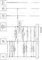
- Figure 5 illustrates an example of how RLF can be handled while sending NAS data in a CP-CloT environment.
- Figure 5 illustrates flows between a UE 200, a source eNB (S_BS) 300A, a core network node 400 (e.g., an MME), a target eNB (T_BS) 300B and signaling gateway/packet gateway (S-GW/P-GW) nodes 500.
- S_BS source eNB
- T_BS target eNB
- S-GW/P-GW signaling gateway/packet gateway
- Steps 1 to 8 are as defined in current specifications.
- the UE 200 sets up an RRC connection with the source base station 300A and sends data over NAS, which is forwarded from the core network node 400 to a S-GW/P-GW node 500.
- DL data to be delivered to the UE 200 by the S/P-GW 500 Step 9
- DL data to be delivered to the UE is encrypted to be sent in a NAS data PDU from the core network node 400 to the source base station 300A using DL NAS transport.
- Step 11 The core network node 400 derives an eNB key (KeNB) using the NAS UL count, that is, the NAS UL count of the NAS message that included the NAS data PDU.
- KeNB eNB key
- Step 12 The core network node 400 sends the KeNB to the source base station 300A in an DL NAS transport message.
- This can be the same DL NAS transport message in which the DL NAS data PDU is sent or some other S1 message from the core network node 400 to the source base station 300.
- the core network node 400 since the core network node 400 knows the chosen token integrity algorithm and the KeNB, the core network node 400 can derive the RRC message integrity key (Krrc_int) and send the RRC message integrity key Krrc_int to the source base station 300A.
- the core network node 400 since the core network node 400 knows the chosen token integrity algorithm and the KeNB, the core network node 400 can derive the RRC message integrity key (Krrc_int) and send the RRC message integrity key Krrc_int to the source base station 300A.
- Step 13 The source base station 300A stores the KeNB, and derives the RRC message integrity key Krrc_int using the integrity algorithm identifier which was indicated by the core network node 400 in step 9 of the Attach procedure of Figure 4 .
- Step 14 The source base station 300A sends the NAS data PDU to the UE 200.
- Step 15 a radio link failure (RLF) happens at this point.
- RLF radio link failure
- a RLF could also happen before the UE 200 has received the DL data.
- the UE 200 starts an RRC connection re-establishment procedure to the target base station (T_BS) 300B.
- the UE 200 derives the eNB key KeNB in a similar manner as the core network node 400 did, and derives the RRC message integrity key Krrc_int from the KeNB in a similar manner as the source base station 300A did.
- the key derivation can happen before this point. For example, the key derivation can happen any time after the UE 200 has received information on the selected integrity algorithm from the core network node 400 and sent the NAS data PDU.
- the UE 200 generates a token using the following inputs to the selected integrity algorithm: Cell-targetCell- ID, source PCI and source C_RNTI (similarly as in RRC resume) and Krrc_int as the key, with the new aspect here being the integrity algorithm.
- Step 19 The UE 200 sends the token to the target base station 300B in an RRC ConnRe-est request (or similar) message.
- Step 20 Upon receiving the token, the target base station 300B sends the token to the source base station 300A in an X2 message (e.g., an X2 context fetch).
- an X2 message e.g., an X2 context fetch
- Step 21 Upon receiving the token, the source base station 300A verifies the token using the RRC message integrity key Krrc_int and the previously stored integrity algorithm (in a procedure similar to an RRC resume). The source base station 300A also checks to see if the target base station 300B is authorized to use the indicated target Cell-ID.
- Step 22 If the checks are ok, the source base station 300A sends the UE context to the target base station 300B in a X2 message (e.g., an X2 context response message).
- a X2 message e.g., an X2 context response message
- Step 23 The target base station 300B stores the received UE context and sends RRC ConnRe-est setup message to the UE 200.
- Step 24 the UE 200 sends the RRC ConnRe-est Complete message to the target base station 300B.
- the RRC connection is now re-established, and an NAS data PDU may be sent in this message.
- the RRC messages may not be protected in the PDCP layer.
- the UE 200 can use a counter for replay protection of tokens.
- the counter can be reset when a new eNB key KeNB is derived.
- a UE 200 establishes an RRC connection with a source base station 300A (Block 602).
- the UE 200 sends an indication of the security capability of the UE 200 to the source base station 300A (Block 604).
- the UE 200 then receives a non-access stratum (NAS) security mode command (SMC) from the source base station 300A.
- the NAS SMC identifies a selected integrity algorithm that the UE 200 can use to generate an RRC message integrity key Krrc_int (Block 606).
- the UE 200 then generates the RRC message integrity key Krrc_int using the selected integrity algorithm (Block 608).
- the UE 200 can then generate an RRC integrity token using the RRC message integrity key Krrc_int (Block 610).
- the UE 200 may transmit the RRC integrity token to a target base station 300B in an RRC ConnRe-est Request message (Block 702) and subsequently receive an RRC ConnRe-est Setup message from the target base station 300B (Block 704).
- RLF radio link failure
- the source base station 300A may establish an RRC connection with a UE 200 (Block 802). Following establishment of the RRC connection, the source base station 300A may receive an indication of a security capability of the UE 200 from the UE 200 (Block 804). The source base station 300A may generate a list of integrity algorithms supported by the eNodeB (Block 806) and transmit the list of supported integrity algorithms to a core network node 400(Block 808).
- the source base station 300A may receive an NAS Transport message from the core network node 400, wherein the NAS Transport message identifies a selected integrity algorithm for generating an RRC message integrity key Krrc_int (Block 810), and send an NAS security mode command (SMC) to the UE 200, wherein the NAS SMC identifies the selected integrity algorithm (Block 812).
- the NAS Transport message identifies a selected integrity algorithm for generating an RRC message integrity key Krrc_int (Block 810)
- SMC NAS security mode command
- the eNodeB may provide the prioritized list of supported integrity algorithms to a core network node 400 during an Attach procedure using S1 signalling.
- the core network node 400 which knows the UE capabilities and the algorithms supported by the source base station 300A, selects an integrity algorithm for the token calculation, and the core network node 400 indicates the selected integrity algorithm to the UE 200 in an NAS SMC and to the source base station 300A in an S1 message.
- the core network node 400 may receive (Block 902), from the source base station 300A, a list of integrity algorithms supported by the eNodeB for generating an RRC message integrity key Krrc_int.
- the core network node 400 selects (Block 904) an integrity algorithm from the list of integrity algorithms, and transmits (Block 906) a message identifying the selected integrity algorithm to the source base station 300A.
- the core network node 400 may also send an eNB key KeNB to the source base station 300A in an S1 message.
- the source base station 300A and UE 200 calculate an RRC message integrity key Krrc_int using the selected algorithm.
- the UE 200 and the source base station 300A calculate and verify the token using the selected algorithm and Krrc_int.
- FIG. 10 is a block diagram illustrating various functional modules of an eNodeB network node 300 according to some embodiments.
- an eNodeB network node 300 may include a radio interface module 1002 for establishing a radio resource control, RRC, connection with a user equipment, and receiving an indication of a security capability of the UE 200 from the UE 200, and an integrity algorithm module 1004 for generating a list of integrity algorithms supported by the eNodeB.
- RRC radio resource control
- an integrity algorithm module 1004 for generating a list of integrity algorithms supported by the eNodeB.
- the radio interface module 1002 is further configured for transmitting the list of supported integrity algorithms to a core network node 400, such as a mobility management entity, MME, receiving from the core network node 400 a selected integrity algorithm for generating an RRC message integrity key Krrc_int, and sending the selected integrity algorithm to the UE 200.
- a core network node 400 such as a mobility management entity, MME
- MME mobility management entity
- FIG 11 is a block diagram illustrating various functional modules of a UE 200 according to some embodiments.
- a UE 200 may include a radio interface module 1102 and a security module 1104.
- the radio interface module 1102 is configured for establishing a radio resource control, RRC, connection with a source base station 300A, sending an indication of a security capability of the UE to the source base station 300A following establishment of the RRC connection, and receiving a non-access stratum, NAS, security mode command, SMC, from the source base station 300A, wherein the NAS SMC identifies a selected integrity algorithm for generating an RRC message integrity key Krrc_int.
- the security module 1104 is configured for generating the RRC message integrity key Krrc_int using the selected integrity algorithm and generating an RRC integrity token using the RRC message integrity key Krrc_int.
- FIG. 12 is a block diagram of a core network node 400 according to some embodiments.
- a core network node 400 may include a radio interface module 1202 for receiving, from an base station 300 that serves a user equipment, UE, a list of integrity algorithms supported by the base station 300 for generating an RRC message integrity key Krrc_int, and an algorithm selection module 1204 for selecting an integrity algorithm from the list of integrity algorithms.
- the radio interface module 1202 is further configured for transmitting a message identifying the selected integrity algorithm to the base station 300.
- the terms “comprise”, “comprising”, “comprises”, “include”, “including”, “includes”, “have”, “has”, “having”, or variants thereof are open-ended, and include one or more stated features, integers, elements, steps, components or functions but does not preclude the presence or addition of one or more other features, integers, elements, steps, components, functions or groups thereof.
- the common abbreviation “e.g.”, which derives from the Latin phrase “exempli gratia” may be used to introduce or specify a general example or examples of a previously mentioned item, and is not intended to be limiting of such item.
- the common abbreviation “i.e.”, which derives from the Latin phrase “id est,” may be used to specify a particular item from a more general recitation.
- Example embodiments are described herein with reference to block diagrams and/or flowchart illustrations of computer-implemented methods, apparatus (systems and/or devices) and/or computer program products. It is understood that a block of the block diagrams and/or flowchart illustrations, and combinations of blocks in the block diagrams and/or flowchart illustrations, can be implemented by computer program instructions that are performed by one or more computer circuits.
- These computer program instructions may be provided to a processor circuit of a general purpose computer circuit, special purpose computer circuit, and/or other programmable data processing circuit to produce a machine, such that the instructions, which execute via the processor of the computer and/or other programmable data processing apparatus, transform and control transistors, values stored in memory locations, and other hardware components within such circuitry to implement the functions/acts specified in the block diagrams and/or flowchart block or blocks, and thereby create means (functionality) and/or structure for implementing the functions/acts specified in the block diagrams and/or flowchart block(s).
- These computer program instructions may also be stored in a tangible computer-readable medium that can direct a computer or other programmable data processing apparatus to function in a particular manner, such that the instructions stored in the computer-readable medium produce an article of manufacture including instructions which implement the functions/acts specified in the block diagrams and/or flowchart block or blocks.
- a tangible, non-transitory computer-readable medium may include an electronic, magnetic, optical, electromagnetic, or semiconductor data storage system, apparatus, or device. More specific examples of the computer-readable medium would include the following: a portable computer diskette, a random access memory (RAM) circuit, a read-only memory (ROM) circuit, an erasable programmable read-only memory (EPROM or Flash memory) circuit, a portable compact disc read-only memory (CD-ROM), and a portable digital video disc read-only memory (DVD/BlueRay).
- RAM random access memory
- ROM read-only memory
- EPROM or Flash memory erasable programmable read-only memory
- CD-ROM compact disc read-only memory
- DVD/BlueRay portable digital video disc read-only memory
- the computer program instructions may also be loaded onto a computer and/or other programmable data processing apparatus to cause a series of operational steps to be performed on the computer and/or other programmable apparatus to produce a computer-implemented process such that the instructions which execute on the computer or other programmable apparatus provide steps for implementing the functions/acts specified in the block diagrams and/or flowchart block or blocks.
- embodiments of the present disclosure may be embodied in hardware and/or in software (including firmware, resident software, micro-code, etc.) that runs on a processor such as a digital signal processor, which may collectively be referred to as "circuitry," "a module” or variants thereof.
Landscapes
- Engineering & Computer Science (AREA)
- Computer Security & Cryptography (AREA)
- Computer Networks & Wireless Communication (AREA)
- Signal Processing (AREA)
- Computer Hardware Design (AREA)
- Computing Systems (AREA)
- General Engineering & Computer Science (AREA)
- Mobile Radio Communication Systems (AREA)
Claims (16)
- Verfahren des Betreibens eines Benutzergeräts (user equipment, UE), umfassend:Herstellen (602) einer Radio-Resource-Control (RRC) -Verbindung mit einer Quellbasisstation;folgend auf die Herstellung der RRC-Verbindung, Senden (604) einer Angabe einer Sicherheitsfähigkeit des UE an die Quellbasisstation;Empfangen (606) einer Non-Access-Stratum (NAS) -Nachricht von der Quellbasisstation, wobeidie NAS-Nachricht einen ausgewählten Sicherheitsalgorithmus identifiziert;Erzeugen (608) des Access-Stratum-Sicherheitsschlüssels, der mit dem ausgewählten Sicherheitsalgorithmus verwendet werden soll;Erzeugen (610) eines RRC-Integritätstokens unter Verwendung des ausgewählten Sicherheitsalgorithmus und des Access-Stratum-Sicherheitsschlüssels; undals Reaktion auf einen Verbindungsfehler zwischen dem UE und der Quellbasisstation, Übertragen des RRC-Integritätstokens an eine Zielbasisstation.
- Verfahren nach Anspruch 1, wobei der ausgewählte Sicherheitsalgorithmus zum Sichern von Access-Stratum-Kommunikationen zwischen dem UE und der Quellbasisstation dient.
- Verfahren nach Anspruch 2, ferner umfassend:
Verwenden des Access-Stratum-Sicherheitsschlüssels und des ausgewählten Sicherheitsalgorithmus, um Access-Stratum-Kommunikationen mit der Quellbasisstation zu schützen. - Verfahren nach einem der Ansprüche 1 bis 3, wobei die NAS-Nachricht einen NAS-Sicherheitsmodusbefehl umfasst.
- Verfahren nach einem der Ansprüche 1 bis 4, wobei die Quellbasisstation eine eNodeB umfasst.
- Verfahren nach einem der Ansprüche 1 bis 5, wobei der ausgewählte Sicherheitsalgorithmus einen Integritätsalgorithmus umfasst.
- Verfahren nach einem der Ansprüche 1 bis 6, wobei der Access-Stratum-Sicherheitsschlüssel einen RRC-Nachricht-Integritätsschlüssel, Krrc_int, umfasst.
- Verfahren nach einem der Ansprüche 1 bis 7, wobei das Senden der Angabe der Sicherheitsfähigkeit des UE an die Quellbasisstation das Senden einer Anfrage an die Quellbasisstation umfasst, wobei die Anfrage die Angabe der Sicherheitsfähigkeit des UE beinhaltet.
- Verfahren nach Anspruch 8, wobei die Anfrage eine Attach-Anfrage umfasst.
- Verfahren nach einem der Ansprüche 1 bis 9, ferner umfassend:Erzeugen eines Basisstationsschlüssels KeNB;wobei das Erzeugen des Access-Stratum-Sicherheitsschlüssels das Erzeugen des Access-Stratum-Sicherheitsschlüssels unter Verwendung des Basisstationsschlüssels KeNB und der ausgewählten Integritätsalgorithmuskennung umfasst.
- Verfahren nach Anspruch 10, wobei der Basisstationsschlüssel KeNB und der Access-Stratum-Sicherheitsschlüssel vor dem Verbindungsfehler erzeugt werden.
- Verfahren nach Anspruch 10, wobei das Übertragen des RRC-Integritätstokens an die Zielbasisstation das Übertragen des Integritätstokens in einer RRC-ConnRe-est-Request-Nachricht umfasst.
- Verfahren nach Anspruch 12, ferner umfassend:Empfangen einer RRC-ConnRe-est-Setup-Nachricht als Reaktion auf die RRC-ConnRe-est-Request-Nachricht; undals Reaktion auf das Empfangen der RRC-ConnRe-est-Setup-Nachricht, Übertragen einer NAS-Daten-Protokolldateneinheit (PDU) an die Zielbasisstation.
- UE (200), umfassend:ein Funkschnittstellenmodul zum Herstellen (602) einer Radio-Resource-Control (RRC) -Verbindung mit einer Quellbasisstation;folgend auf die Herstellung der RRC-Verbindung, Senden (604) einer Angabe einer Sicherheitsfähigkeit des UE an die Basisstation; undEmpfangen (606) einer Non-Access-Stratum (NAS) -Nachricht von der Quellbasisstation, wobeidie NAS-Nachricht einen ausgewählten Sicherheitsalgorithmus identifiziert; undein Sicherheitsmodul zum Erzeugen (608) des Access-Stratum-Sicherheitsschlüssels, der mit dem ausgewählten Sicherheitsalgorithmus verwendet werden soll, Erzeugen (610) eines RRC-Integritätstokens unter Verwendung des ausgewählten Sicherheitsalgorithmus und des Access-Stratum-Sicherheitsschlüssels; und als Reaktion auf einen Verbindungsfehler zwischen dem UE und der Quellbasisstation, Übertragen des RRC-Integritätstokens an eine Zielbasisstation.
- Verfahren des Betreibens eines Netzwerkknotens (300) eines zellularen Funkzugangsnetzes (radio access network, RAN), wobei der Netzwerkknoten eine Quellbasisstation für ein Benutzergerät (user equipment, UE) ist, wobei das Verfahren Folgendes umfasst:Herstellen (802) einer Radio-Resource-Control (RRC) -Verbindung mit dem UE;folgend auf die Herstellung der RRC-Verbindung Empfangen (804) einer Angabe einer Sicherheitsfähigkeit des UE von dem UE;Erzeugen (806) einer Liste von Sicherheitsalgorithmen, die durch den Netzwerkknoten (300) unterstützt werden;Übertragen (808) der Liste von unterstützten Sicherheitsalgorithmen an einen Kernnetzwerkknoten;Empfangen (810), von dem Netzwerkknoten, eines ausgewählten Sicherheitsalgorithmus;Senden (812) des ausgewählten Sicherheitsalgorithmus an das UE;als Reaktion auf einen Verbindungsfehler zwischen dem UE und der Quellbasisstation:Empfangen eines RRC-Integritätstokens von einer Zielbasisstation für das UE;Verifizieren des RRC-Integritätstokens unter Verwendung des ausgewählten Sicherheitsalgorithmus und eines RRC-Nachricht-Integritätsschlüssels; undals Reaktion auf die Verifikation des RRC-Integritätstokens, Senden eines Kontexts des UE an die Zielbasisstation.
- Netzwerkknoten (300), der konfiguriert ist für einen Betrieb in einem zellularen Funkzugangsnetz (radio access network, RAN), wobei der Netzwerkknoten eine Quellbasisstation für ein Benutzergerät (user equipment, UE) ist, umfassend:ein Funkschnittstellenmodul zum Herstellen (802) einer Radio-Resource-Control (RRC) -Verbindung mit einem Benutzergerät, und Empfangen (804) einer Angabe einer Sicherheitsfähigkeit des UE von dem UE; undein Sicherheitsalgorithmusmodul zum Erzeugen (806) einer Liste von Sicherheitsalgorithmen, die durch den Netzwerkknoten (300) unterstützt werden;wobei das Funkschnittstellenmodul ferner konfiguriert ist zum Übertragen (808) der Liste von unterstützten Sicherheitsalgorithmen an einen Kernnetzwerkknoten, Empfangen (810) von dem Kernnetzwerkknoten eines ausgewählten Sicherheitsalgorithmus, Senden (812) des ausgewählten Sicherheitsalgorithmus an das UE und - als Reaktion auf einen Verbindungsfehler zwischen dem UE und der Quellbasisstation - Empfangen eines RRC-Integritätstokens von einer Zielbasisstation für das UE, Verifizieren des RRC-Integritätstokens unter Verwendung des ausgewählten Sicherheitsalgorithmus und eines RRC-Nachricht-Integritätsschlüssels, und - als Reaktion auf die Verifizierung des RRC-Integritätstokens - Senden eines Kontexts des UE an die Zielbasisstation.
Applications Claiming Priority (2)
| Application Number | Priority Date | Filing Date | Title |
|---|---|---|---|
| US201662418487P | 2016-11-07 | 2016-11-07 | |
| PCT/EP2017/078012 WO2018083151A1 (en) | 2016-11-07 | 2017-11-02 | Handling radio link failure in a narrow bandwidth internet of things control plane |
Publications (2)
| Publication Number | Publication Date |
|---|---|
| EP3536000A1 EP3536000A1 (de) | 2019-09-11 |
| EP3536000B1 true EP3536000B1 (de) | 2021-07-21 |
Family
ID=60473478
Family Applications (1)
| Application Number | Title | Priority Date | Filing Date |
|---|---|---|---|
| EP17804457.4A Active EP3536000B1 (de) | 2016-11-07 | 2017-11-02 | Handhabung von funkverbindungsfehlern in der steuerungsebene eines schmalbandigen internet der dinge |
Country Status (3)
| Country | Link |
|---|---|
| US (1) | US11799916B2 (de) |
| EP (1) | EP3536000B1 (de) |
| WO (1) | WO2018083151A1 (de) |
Families Citing this family (7)
| Publication number | Priority date | Publication date | Assignee | Title |
|---|---|---|---|---|
| ES2845874T3 (es) | 2017-01-30 | 2021-07-28 | Ericsson Telefon Ab L M | Métodos y aparatos para restablecer una conexión de control de recurso de radio(RRC) |
| WO2019161538A1 (zh) * | 2018-02-23 | 2019-08-29 | Oppo广东移动通信有限公司 | 一种安全算法的确定方法及装置、计算机存储介质 |
| CN112889317A (zh) * | 2018-10-23 | 2021-06-01 | Oppo广东移动通信有限公司 | 一种安全算法的处理方法及装置、终端 |
| CN111212432B (zh) * | 2018-11-21 | 2023-04-28 | 中国移动通信集团江西有限公司 | 定位伪基站的方法、装置、设备和介质 |
| CN112087747A (zh) * | 2019-06-14 | 2020-12-15 | 苹果公司 | 改善的rrc过程安全性 |
| JP2023500194A (ja) * | 2019-11-11 | 2023-01-05 | テレフオンアクチーボラゲット エルエム エリクソン(パブル) | 無線リソース制御メッセージの完全性保護 |
| EP4104080A1 (de) * | 2020-02-14 | 2022-12-21 | Telefonaktiebolaget Lm Ericsson (Publ) | Schutz der übertragung von fähigkeitsinformationen in einem drahtlosen kommunikationsnetz |
Family Cites Families (7)
| Publication number | Priority date | Publication date | Assignee | Title |
|---|---|---|---|---|
| EP1973265A1 (de) * | 2007-03-21 | 2008-09-24 | Nokia Siemens Networks Gmbh & Co. Kg | Schlüssel auffrischung in einem SAE/LTE Sytem |
| GB2454204A (en) * | 2007-10-31 | 2009-05-06 | Nec Corp | Core network selecting security algorithms for use between a base station and a user device |
| US9276909B2 (en) * | 2008-08-27 | 2016-03-01 | Qualcomm Incorporated | Integrity protection and/or ciphering for UE registration with a wireless network |
| JP5164122B2 (ja) * | 2009-07-04 | 2013-03-13 | 株式会社エヌ・ティ・ティ・ドコモ | 移動通信方法及び移動通信システム |
| CN101925050B (zh) * | 2010-08-19 | 2014-12-03 | 华为技术有限公司 | 一种安全上下文的生成方法及装置 |
| US9155121B2 (en) * | 2012-03-27 | 2015-10-06 | Blackberry Limited | Re-establishment of suspended RRC connection at a different eNB |
| US9497673B2 (en) * | 2013-11-01 | 2016-11-15 | Blackberry Limited | Method and apparatus to enable multiple wireless connections |
-
2017
- 2017-11-02 WO PCT/EP2017/078012 patent/WO2018083151A1/en unknown
- 2017-11-02 US US16/347,660 patent/US11799916B2/en active Active
- 2017-11-02 EP EP17804457.4A patent/EP3536000B1/de active Active
Non-Patent Citations (1)
| Title |
|---|
| None * |
Also Published As
| Publication number | Publication date |
|---|---|
| US11799916B2 (en) | 2023-10-24 |
| EP3536000A1 (de) | 2019-09-11 |
| WO2018083151A1 (en) | 2018-05-11 |
| US20190320318A1 (en) | 2019-10-17 |
Similar Documents
| Publication | Publication Date | Title |
|---|---|---|
| EP3536000B1 (de) | Handhabung von funkverbindungsfehlern in der steuerungsebene eines schmalbandigen internet der dinge | |
| US11653199B2 (en) | Multi-RAT access stratum security | |
| US11589274B2 (en) | Security protection method, apparatus, and system | |
| EP3449608B1 (de) | Verbesserte sicherheit für non-access-stratum | |
| EP3278530B1 (de) | Authentifizierung und schlüsselvereinbarung mit perfekter vorwärtssicherheit | |
| JP6708626B2 (ja) | 無線アクセス・ネットワークからセキュリティを提供する方法およびシステム。 | |
| EP2910044B1 (de) | Verfahren und vorrichtung zur erzeugung eines schlüssels für d2d-kommunikation zwischen einem ersten benutzergerät und zweiten benutzergerät | |
| US20170359719A1 (en) | Key generation method, device, and system | |
| US20100172500A1 (en) | Method of handling inter-system handover security in wireless communications system and related communication device | |
| EP3061222B1 (de) | Gesteuerte bereitstellung von nachweisen zwischen benutzergeräten | |
| CN109906624B (zh) | 支持无线通信网络中的认证的方法以及相关网络节点和无线终端 | |
| CN107113608B (zh) | 使用密钥扩展乘数来生成多个共享密钥的方法和装置 | |
| CN110235459B (zh) | 用于重新建立无线电资源控制(rrc)连接的方法及装置 | |
| KR20190125487A (ko) | 통신 네트워크에서 사용하기 위한 네트워크 노드, 통신 디바이스 및 이를 동작시키는 방법들 | |
| CN116390179A (zh) | 无线网络中的安全小区重定向 | |
| WO2020056433A2 (en) | SECURE COMMUNICATION OF RADIO RESOURCE CONTROL (RRC) REQUEST OVER SIGNAL RADIO BEARER ZERO (SRBo) | |
| EP3610695B1 (de) | Handhabung einer rrc-verbindungslösung | |
| US11606768B2 (en) | Method and apparatus for registration | |
| CN109842881B (zh) | 通信方法、相关设备以及系统 | |
| CN113396637B (zh) | 一种通信的方法、装置及系统 | |
| CN112154682B (zh) | 密钥更新方法、设备和存储介质 | |
| CN115175181A (zh) | 一种通信的方法及装置 | |
| CN112771927A (zh) | 通过无线电接入网络寻呼的用户设备上下文转移 |
Legal Events
| Date | Code | Title | Description |
|---|---|---|---|
| STAA | Information on the status of an ep patent application or granted ep patent |
Free format text: STATUS: UNKNOWN |
|
| STAA | Information on the status of an ep patent application or granted ep patent |
Free format text: STATUS: THE INTERNATIONAL PUBLICATION HAS BEEN MADE |
|
| PUAI | Public reference made under article 153(3) epc to a published international application that has entered the european phase |
Free format text: ORIGINAL CODE: 0009012 |
|
| STAA | Information on the status of an ep patent application or granted ep patent |
Free format text: STATUS: REQUEST FOR EXAMINATION WAS MADE |
|
| 17P | Request for examination filed |
Effective date: 20190423 |
|
| AK | Designated contracting states |
Kind code of ref document: A1 Designated state(s): AL AT BE BG CH CY CZ DE DK EE ES FI FR GB GR HR HU IE IS IT LI LT LU LV MC MK MT NL NO PL PT RO RS SE SI SK SM TR |
|
| AX | Request for extension of the european patent |
Extension state: BA ME |
|
| DAV | Request for validation of the european patent (deleted) | ||
| DAX | Request for extension of the european patent (deleted) | ||
| STAA | Information on the status of an ep patent application or granted ep patent |
Free format text: STATUS: EXAMINATION IS IN PROGRESS |
|
| STAA | Information on the status of an ep patent application or granted ep patent |
Free format text: STATUS: EXAMINATION IS IN PROGRESS |
|
| 17Q | First examination report despatched |
Effective date: 20201103 |
|
| GRAP | Despatch of communication of intention to grant a patent |
Free format text: ORIGINAL CODE: EPIDOSNIGR1 |
|
| STAA | Information on the status of an ep patent application or granted ep patent |
Free format text: STATUS: GRANT OF PATENT IS INTENDED |
|
| RIC1 | Information provided on ipc code assigned before grant |
Ipc: H04W 12/108 20210101ALI20210303BHEP Ipc: H04W 12/106 20210101ALI20210303BHEP Ipc: H04W 4/70 20180101ALI20210303BHEP Ipc: H04W 12/041 20210101ALI20210303BHEP Ipc: H04W 60/04 20090101ALI20210303BHEP Ipc: H04L 29/06 20060101ALI20210303BHEP Ipc: H04W 12/04 20210101AFI20210303BHEP |
|
| INTG | Intention to grant announced |
Effective date: 20210319 |
|
| GRAS | Grant fee paid |
Free format text: ORIGINAL CODE: EPIDOSNIGR3 |
|
| GRAA | (expected) grant |
Free format text: ORIGINAL CODE: 0009210 |
|
| STAA | Information on the status of an ep patent application or granted ep patent |
Free format text: STATUS: THE PATENT HAS BEEN GRANTED |
|
| AK | Designated contracting states |
Kind code of ref document: B1 Designated state(s): AL AT BE BG CH CY CZ DE DK EE ES FI FR GB GR HR HU IE IS IT LI LT LU LV MC MK MT NL NO PL PT RO RS SE SI SK SM TR |
|
| REG | Reference to a national code |
Ref country code: GB Ref legal event code: FG4D |
|
| REG | Reference to a national code |
Ref country code: CH Ref legal event code: EP |
|
| REG | Reference to a national code |
Ref country code: DE Ref legal event code: R096 Ref document number: 602017042592 Country of ref document: DE |
|
| REG | Reference to a national code |
Ref country code: AT Ref legal event code: REF Ref document number: 1413763 Country of ref document: AT Kind code of ref document: T Effective date: 20210815 |
|
| REG | Reference to a national code |
Ref country code: IE Ref legal event code: FG4D |
|
| REG | Reference to a national code |
Ref country code: NL Ref legal event code: FP |
|
| REG | Reference to a national code |
Ref country code: LT Ref legal event code: MG9D |
|
| REG | Reference to a national code |
Ref country code: AT Ref legal event code: MK05 Ref document number: 1413763 Country of ref document: AT Kind code of ref document: T Effective date: 20210721 |
|
| PG25 | Lapsed in a contracting state [announced via postgrant information from national office to epo] |
Ref country code: RS Free format text: LAPSE BECAUSE OF FAILURE TO SUBMIT A TRANSLATION OF THE DESCRIPTION OR TO PAY THE FEE WITHIN THE PRESCRIBED TIME-LIMIT Effective date: 20210721 Ref country code: SE Free format text: LAPSE BECAUSE OF FAILURE TO SUBMIT A TRANSLATION OF THE DESCRIPTION OR TO PAY THE FEE WITHIN THE PRESCRIBED TIME-LIMIT Effective date: 20210721 Ref country code: HR Free format text: LAPSE BECAUSE OF FAILURE TO SUBMIT A TRANSLATION OF THE DESCRIPTION OR TO PAY THE FEE WITHIN THE PRESCRIBED TIME-LIMIT Effective date: 20210721 Ref country code: FI Free format text: LAPSE BECAUSE OF FAILURE TO SUBMIT A TRANSLATION OF THE DESCRIPTION OR TO PAY THE FEE WITHIN THE PRESCRIBED TIME-LIMIT Effective date: 20210721 Ref country code: ES Free format text: LAPSE BECAUSE OF FAILURE TO SUBMIT A TRANSLATION OF THE DESCRIPTION OR TO PAY THE FEE WITHIN THE PRESCRIBED TIME-LIMIT Effective date: 20210721 Ref country code: AT Free format text: LAPSE BECAUSE OF FAILURE TO SUBMIT A TRANSLATION OF THE DESCRIPTION OR TO PAY THE FEE WITHIN THE PRESCRIBED TIME-LIMIT Effective date: 20210721 Ref country code: BG Free format text: LAPSE BECAUSE OF FAILURE TO SUBMIT A TRANSLATION OF THE DESCRIPTION OR TO PAY THE FEE WITHIN THE PRESCRIBED TIME-LIMIT Effective date: 20211021 Ref country code: LT Free format text: LAPSE BECAUSE OF FAILURE TO SUBMIT A TRANSLATION OF THE DESCRIPTION OR TO PAY THE FEE WITHIN THE PRESCRIBED TIME-LIMIT Effective date: 20210721 Ref country code: PT Free format text: LAPSE BECAUSE OF FAILURE TO SUBMIT A TRANSLATION OF THE DESCRIPTION OR TO PAY THE FEE WITHIN THE PRESCRIBED TIME-LIMIT Effective date: 20211122 Ref country code: NO Free format text: LAPSE BECAUSE OF FAILURE TO SUBMIT A TRANSLATION OF THE DESCRIPTION OR TO PAY THE FEE WITHIN THE PRESCRIBED TIME-LIMIT Effective date: 20211021 |
|
| PG25 | Lapsed in a contracting state [announced via postgrant information from national office to epo] |
Ref country code: PL Free format text: LAPSE BECAUSE OF FAILURE TO SUBMIT A TRANSLATION OF THE DESCRIPTION OR TO PAY THE FEE WITHIN THE PRESCRIBED TIME-LIMIT Effective date: 20210721 Ref country code: LV Free format text: LAPSE BECAUSE OF FAILURE TO SUBMIT A TRANSLATION OF THE DESCRIPTION OR TO PAY THE FEE WITHIN THE PRESCRIBED TIME-LIMIT Effective date: 20210721 Ref country code: GR Free format text: LAPSE BECAUSE OF FAILURE TO SUBMIT A TRANSLATION OF THE DESCRIPTION OR TO PAY THE FEE WITHIN THE PRESCRIBED TIME-LIMIT Effective date: 20211022 |
|
| REG | Reference to a national code |
Ref country code: DE Ref legal event code: R097 Ref document number: 602017042592 Country of ref document: DE |
|
| PG25 | Lapsed in a contracting state [announced via postgrant information from national office to epo] |
Ref country code: DK Free format text: LAPSE BECAUSE OF FAILURE TO SUBMIT A TRANSLATION OF THE DESCRIPTION OR TO PAY THE FEE WITHIN THE PRESCRIBED TIME-LIMIT Effective date: 20210721 |
|
| PLBE | No opposition filed within time limit |
Free format text: ORIGINAL CODE: 0009261 |
|
| STAA | Information on the status of an ep patent application or granted ep patent |
Free format text: STATUS: NO OPPOSITION FILED WITHIN TIME LIMIT |
|
| PG25 | Lapsed in a contracting state [announced via postgrant information from national office to epo] |
Ref country code: SM Free format text: LAPSE BECAUSE OF FAILURE TO SUBMIT A TRANSLATION OF THE DESCRIPTION OR TO PAY THE FEE WITHIN THE PRESCRIBED TIME-LIMIT Effective date: 20210721 Ref country code: SK Free format text: LAPSE BECAUSE OF FAILURE TO SUBMIT A TRANSLATION OF THE DESCRIPTION OR TO PAY THE FEE WITHIN THE PRESCRIBED TIME-LIMIT Effective date: 20210721 Ref country code: RO Free format text: LAPSE BECAUSE OF FAILURE TO SUBMIT A TRANSLATION OF THE DESCRIPTION OR TO PAY THE FEE WITHIN THE PRESCRIBED TIME-LIMIT Effective date: 20210721 Ref country code: EE Free format text: LAPSE BECAUSE OF FAILURE TO SUBMIT A TRANSLATION OF THE DESCRIPTION OR TO PAY THE FEE WITHIN THE PRESCRIBED TIME-LIMIT Effective date: 20210721 Ref country code: CZ Free format text: LAPSE BECAUSE OF FAILURE TO SUBMIT A TRANSLATION OF THE DESCRIPTION OR TO PAY THE FEE WITHIN THE PRESCRIBED TIME-LIMIT Effective date: 20210721 Ref country code: AL Free format text: LAPSE BECAUSE OF FAILURE TO SUBMIT A TRANSLATION OF THE DESCRIPTION OR TO PAY THE FEE WITHIN THE PRESCRIBED TIME-LIMIT Effective date: 20210721 |
|
| 26N | No opposition filed |
Effective date: 20220422 |
|
| PG25 | Lapsed in a contracting state [announced via postgrant information from national office to epo] |
Ref country code: MC Free format text: LAPSE BECAUSE OF FAILURE TO SUBMIT A TRANSLATION OF THE DESCRIPTION OR TO PAY THE FEE WITHIN THE PRESCRIBED TIME-LIMIT Effective date: 20210721 |
|
| REG | Reference to a national code |
Ref country code: CH Ref legal event code: PL |
|
| PG25 | Lapsed in a contracting state [announced via postgrant information from national office to epo] |
Ref country code: LU Free format text: LAPSE BECAUSE OF NON-PAYMENT OF DUE FEES Effective date: 20211102 Ref country code: IT Free format text: LAPSE BECAUSE OF FAILURE TO SUBMIT A TRANSLATION OF THE DESCRIPTION OR TO PAY THE FEE WITHIN THE PRESCRIBED TIME-LIMIT Effective date: 20210721 Ref country code: BE Free format text: LAPSE BECAUSE OF NON-PAYMENT OF DUE FEES Effective date: 20211130 |
|
| REG | Reference to a national code |
Ref country code: BE Ref legal event code: MM Effective date: 20211130 |
|
| PG25 | Lapsed in a contracting state [announced via postgrant information from national office to epo] |
Ref country code: IE Free format text: LAPSE BECAUSE OF NON-PAYMENT OF DUE FEES Effective date: 20211102 |
|
| PG25 | Lapsed in a contracting state [announced via postgrant information from national office to epo] |
Ref country code: FR Free format text: LAPSE BECAUSE OF NON-PAYMENT OF DUE FEES Effective date: 20211130 |
|
| PG25 | Lapsed in a contracting state [announced via postgrant information from national office to epo] |
Ref country code: CY Free format text: LAPSE BECAUSE OF FAILURE TO SUBMIT A TRANSLATION OF THE DESCRIPTION OR TO PAY THE FEE WITHIN THE PRESCRIBED TIME-LIMIT Effective date: 20210721 |
|
| PG25 | Lapsed in a contracting state [announced via postgrant information from national office to epo] |
Ref country code: LI Free format text: LAPSE BECAUSE OF NON-PAYMENT OF DUE FEES Effective date: 20220630 Ref country code: HU Free format text: LAPSE BECAUSE OF FAILURE TO SUBMIT A TRANSLATION OF THE DESCRIPTION OR TO PAY THE FEE WITHIN THE PRESCRIBED TIME-LIMIT; INVALID AB INITIO Effective date: 20171102 Ref country code: CH Free format text: LAPSE BECAUSE OF NON-PAYMENT OF DUE FEES Effective date: 20220630 |
|
| PGFP | Annual fee paid to national office [announced via postgrant information from national office to epo] |
Ref country code: NL Payment date: 20231126 Year of fee payment: 7 |
|
| PGFP | Annual fee paid to national office [announced via postgrant information from national office to epo] |
Ref country code: GB Payment date: 20231127 Year of fee payment: 7 |
|
| PGFP | Annual fee paid to national office [announced via postgrant information from national office to epo] |
Ref country code: DE Payment date: 20231129 Year of fee payment: 7 |
|
| PG25 | Lapsed in a contracting state [announced via postgrant information from national office to epo] |
Ref country code: MK Free format text: LAPSE BECAUSE OF FAILURE TO SUBMIT A TRANSLATION OF THE DESCRIPTION OR TO PAY THE FEE WITHIN THE PRESCRIBED TIME-LIMIT Effective date: 20210721 |