EP3535914B1 - Decoupling of synchronization raster and channel raster - Google Patents
Decoupling of synchronization raster and channel raster Download PDFInfo
- Publication number
- EP3535914B1 EP3535914B1 EP17804025.9A EP17804025A EP3535914B1 EP 3535914 B1 EP3535914 B1 EP 3535914B1 EP 17804025 A EP17804025 A EP 17804025A EP 3535914 B1 EP3535914 B1 EP 3535914B1
- Authority
- EP
- European Patent Office
- Prior art keywords
- channel raster
- synchronization
- frequency
- synchronization channel
- raster
- Prior art date
- Legal status (The legal status is an assumption and is not a legal conclusion. Google has not performed a legal analysis and makes no representation as to the accuracy of the status listed.)
- Active
Links
- 238000004891 communication Methods 0.000 claims description 84
- 230000006854 communication Effects 0.000 claims description 84
- 238000000034 method Methods 0.000 claims description 39
- 238000004590 computer program Methods 0.000 claims description 2
- 238000005516 engineering process Methods 0.000 description 36
- 238000010586 diagram Methods 0.000 description 16
- 230000005540 biological transmission Effects 0.000 description 13
- 230000006870 function Effects 0.000 description 13
- 239000000969 carrier Substances 0.000 description 10
- 238000001228 spectrum Methods 0.000 description 9
- 238000005259 measurement Methods 0.000 description 8
- 238000001514 detection method Methods 0.000 description 6
- 230000002776 aggregation Effects 0.000 description 4
- 238000004220 aggregation Methods 0.000 description 4
- 238000013461 design Methods 0.000 description 4
- 230000007774 longterm Effects 0.000 description 4
- 230000003287 optical effect Effects 0.000 description 4
- 230000001413 cellular effect Effects 0.000 description 2
- 239000000835 fiber Substances 0.000 description 2
- 230000008520 organization Effects 0.000 description 2
- 239000002245 particle Substances 0.000 description 2
- 230000008569 process Effects 0.000 description 2
- 230000011664 signaling Effects 0.000 description 2
- 238000005766 Middleton reaction Methods 0.000 description 1
- 108010076504 Protein Sorting Signals Proteins 0.000 description 1
- 238000013475 authorization Methods 0.000 description 1
- 230000008901 benefit Effects 0.000 description 1
- 230000007175 bidirectional communication Effects 0.000 description 1
- 239000003795 chemical substances by application Substances 0.000 description 1
- 210000001520 comb Anatomy 0.000 description 1
- 230000001419 dependent effect Effects 0.000 description 1
- 238000012423 maintenance Methods 0.000 description 1
- 238000013507 mapping Methods 0.000 description 1
- 239000011159 matrix material Substances 0.000 description 1
- 238000010295 mobile communication Methods 0.000 description 1
- 230000011218 segmentation Effects 0.000 description 1
- 230000001360 synchronised effect Effects 0.000 description 1
- 238000012546 transfer Methods 0.000 description 1
Images

Classifications
-
- H—ELECTRICITY
- H04—ELECTRIC COMMUNICATION TECHNIQUE
- H04L—TRANSMISSION OF DIGITAL INFORMATION, e.g. TELEGRAPHIC COMMUNICATION
- H04L5/00—Arrangements affording multiple use of the transmission path
- H04L5/003—Arrangements for allocating sub-channels of the transmission path
- H04L5/0048—Allocation of pilot signals, i.e. of signals known to the receiver
-
- H—ELECTRICITY
- H04—ELECTRIC COMMUNICATION TECHNIQUE
- H04L—TRANSMISSION OF DIGITAL INFORMATION, e.g. TELEGRAPHIC COMMUNICATION
- H04L5/00—Arrangements affording multiple use of the transmission path
- H04L5/003—Arrangements for allocating sub-channels of the transmission path
- H04L5/0053—Allocation of signaling, i.e. of overhead other than pilot signals
-
- H—ELECTRICITY
- H04—ELECTRIC COMMUNICATION TECHNIQUE
- H04W—WIRELESS COMMUNICATION NETWORKS
- H04W56/00—Synchronisation arrangements
- H04W56/001—Synchronization between nodes
-
- H—ELECTRICITY
- H04—ELECTRIC COMMUNICATION TECHNIQUE
- H04W—WIRELESS COMMUNICATION NETWORKS
- H04W72/00—Local resource management
- H04W72/20—Control channels or signalling for resource management
- H04W72/23—Control channels or signalling for resource management in the downlink direction of a wireless link, i.e. towards a terminal
-
- H—ELECTRICITY
- H04—ELECTRIC COMMUNICATION TECHNIQUE
- H04L—TRANSMISSION OF DIGITAL INFORMATION, e.g. TELEGRAPHIC COMMUNICATION
- H04L5/00—Arrangements affording multiple use of the transmission path
- H04L5/0001—Arrangements for dividing the transmission path
- H04L5/0003—Two-dimensional division
- H04L5/0005—Time-frequency
- H04L5/0007—Time-frequency the frequencies being orthogonal, e.g. OFDM(A), DMT
- H04L5/001—Time-frequency the frequencies being orthogonal, e.g. OFDM(A), DMT the frequencies being arranged in component carriers
-
- H—ELECTRICITY
- H04—ELECTRIC COMMUNICATION TECHNIQUE
- H04L—TRANSMISSION OF DIGITAL INFORMATION, e.g. TELEGRAPHIC COMMUNICATION
- H04L5/00—Arrangements affording multiple use of the transmission path
- H04L5/003—Arrangements for allocating sub-channels of the transmission path
- H04L5/0048—Allocation of pilot signals, i.e. of signals known to the receiver
- H04L5/0051—Allocation of pilot signals, i.e. of signals known to the receiver of dedicated pilots, i.e. pilots destined for a single user or terminal
-
- H—ELECTRICITY
- H04—ELECTRIC COMMUNICATION TECHNIQUE
- H04L—TRANSMISSION OF DIGITAL INFORMATION, e.g. TELEGRAPHIC COMMUNICATION
- H04L5/00—Arrangements affording multiple use of the transmission path
- H04L5/003—Arrangements for allocating sub-channels of the transmission path
- H04L5/0053—Allocation of signaling, i.e. of overhead other than pilot signals
- H04L5/0055—Physical resource allocation for ACK/NACK
-
- H—ELECTRICITY
- H04—ELECTRIC COMMUNICATION TECHNIQUE
- H04L—TRANSMISSION OF DIGITAL INFORMATION, e.g. TELEGRAPHIC COMMUNICATION
- H04L5/00—Arrangements affording multiple use of the transmission path
- H04L5/003—Arrangements for allocating sub-channels of the transmission path
- H04L5/0053—Allocation of signaling, i.e. of overhead other than pilot signals
- H04L5/0057—Physical resource allocation for CQI
Definitions
- aspects of the present disclosure relates generally to communication systems, and more particularly, to decoupling of a synchronization (“sync”) channel raster and a channel raster in a wireless communication system.
- sync synchronization
- Wireless communication systems are widely deployed to provide various telecommunication services such as telephony, video, data, messaging, and broadcasts.
- Typical wireless communication systems may employ multiple-access technologies capable of supporting communication with multiple users by sharing available system resources (e.g., bandwidth, transmit power).
- multiple-access technologies include code division multiple access (CDMA) systems, wideband CDMA (W-CDMA) systems, time division multiple access (TDMA) systems, frequency division multiple access (FDMA) systems, orthogonal frequency division multiple access (OFDMA) systems, wide band single-carrier frequency division multiple access (SC-FDMA) systems, and time division synchronous code division multiple access (TD-SCDMA) systems.
- CDMA code division multiple access
- W-CDMA wideband CDMA
- TDMA time division multiple access
- FDMA frequency division multiple access
- OFDMA orthogonal frequency division multiple access
- SC-FDMA wide band single-carrier frequency division multiple access
- TD-SCDMA time division synchronous code division multiple access
- 5G NR new radio
- 5G communications technology includes enhanced mobile broadband addressing human-centric use cases for access to multimedia content, services and data; ultra-reliable-low latency communications (URLLC) with requirements, especially in terms of latency and reliability; and massive machine type communications for a very large number of connected devices, and typically transmitting a relatively low volume of non-delay-sensitive information.
- URLLC ultra-reliable-low latency communications
- massive machine type communications for a very large number of connected devices, and typically transmitting a relatively low volume of non-delay-sensitive information.
- these improvements should be applicable to other multi-access technologies and the telecommunication standards that employ these technologies.
- the UE During initial acquisition at a user equipment (LTE) in long term evolution (LTE) networks, the UE performs a frequency scan first.
- the UE searches for a carrier center frequency by scanning through configured frequency bands.
- a channel raster e.g., 100 kHz in LTE
- the UE may detect a set of center frequency candidates (e.g., by a downlink power spectrum measurement or waveform detection) over which the synchronization signals could be detected.
- a channel raster e.g. 100 kHz in LTE
- the UE may detect a set of center frequency candidates (e.g., by a downlink power spectrum measurement or waveform detection) over which the synchronization signals could be detected.
- a set of center frequency candidates e.g., by a downlink power spectrum measurement or waveform detection
- NR/LTE networks there may be confusion between NR/LTE networks, as both NR and LTE employ OFDM based waveforms in the downlink.
- "alien" waveform confusion may occur when some massive Machine Type Communications (mMTC) waveforms or some on-demand signals exist in the frequency band.
- mMTC massive Machine Type Communications
- a method for decoupling of a synchronization channel raster and a channel raster for wireless communications include determining, at a network entity, a synchronization channel raster corresponding to a set of frequencies.
- the described aspects further include transmitting, from the network entity, one or more synchronization signals and a physical broadcast channel (PBCH) in any frequency of the set of frequencies of the synchronization channel raster to at least one user equipment (UE).
- PBCH physical broadcast channel
- an apparatus such as a network entity, for decoupling of a synchronization channel raster and a channel raster for wireless communications may include a transceiver, a memory, and at least one processor coupled with the memory and configured to determine, at the network entity, a synchronization channel raster corresponding to a set of frequencies.
- the described aspects further transmit, from the network entity, one or more synchronization signals and a PBCH in any frequency of the set of frequencies of the synchronization channel raster to at least one UE.
- a computer-readable medium may store computer executable code for decoupling of a synchronization channel raster and a channel raster for wireless communications.
- the described aspects include code for determining, at a network entity, a synchronization channel raster corresponding to a set of frequencies.
- the described aspects further include code for transmitting, from the network entity, one or more synchronization signals and a PBCH in any frequency of the set of frequencies of the synchronization channel raster to at least one UE.
- an apparatus for decoupling of a synchronization channel raster and a channel raster for wireless communications includes means for determining, at a network entity, a synchronization channel raster corresponding to a set of frequencies.
- the described aspects further include means for transmitting, from the network entity, one or more synchronization signals and a PBCH in any frequency of the set of frequencies of the synchronization channel raster to at least one UE.
- a method for decoupling of a synchronization channel raster and a channel raster for wireless communications include detecting, at a UE, one or more synchronization signals for timing and frequency synchronization with a network entity and a physical cell identifier (ID) for each frequency of a synchronization channel raster.
- the described aspects further include retrieving, at the UE, a master information block (MIB) by decoding a PBCH transmitted from the network entity.
- MIB master information block
- the described aspects further include searching, by the UE, for a center frequency based at least on detecting the one or more synchronization signals and retrieving the MIB.
- the described aspects further retrieve, at the UE, a MIB by decoding a PBCH transmitted from the network entity.
- the described aspects further search, by the UE, for a center frequency based at least on detecting the one or more synchronization signals and retrieving the MIB.
- a computer-readable medium may store computer executable code for decoupling of a synchronization channel raster and a channel raster for wireless communications.
- the described aspects include code for detecting, at a UE, one or more synchronization signals for a timing and a frequency synchronization with a network entity and a physical cell ID for each frequency of a synchronization channel raster.
- the described aspects further include code for retrieving, at the UE, a MIB by decoding a PBCH transmitted from the network entity.
- the described aspects further include code for searching, by the UE, for a center frequency based at least on detecting the one or more synchronization signals and retrieving the MIB.
- an apparatus for decoupling of a synchronization channel raster and a channel raster for wireless communications includes means for detecting, at a UE, one or more synchronization signals for a timing and a frequency synchronization with a network entity and a physical cell ID for each frequency of a synchronization channel raster.
- the described aspects further include means for retrieving, at the UE, a MIB by decoding a PBCH transmitted from the network entity.
- the described aspects further include means for searching, by the UE, for a center frequency based at least on detecting the one or more synchronization signals and retrieving the MIB.
- a method for decoupling of a synchronization channel raster and a channel raster for wireless communications include determining, at a network entity, a synchronization channel raster corresponding to a set of frequencies.
- the described aspects further include transmitting, from the network entity, one or more synchronization signals and a PBCH in a frequency of the set of frequencies of the synchronization channel raster closest to a center frequency of a bandwidth to at least one UE.
- the described aspects further transmit, from the network entity, one or more synchronization signals and a PBCH in a frequency of the set of frequencies of the synchronization channel raster closest to a center frequency of a bandwidth to at least one UE.
- a computer-readable medium may store computer executable code for decoupling of a synchronization channel raster and a channel raster for wireless communications.
- the described aspects include code for determining, at a network entity, a synchronization channel raster corresponding to a set of frequencies.
- the described aspects further include code for transmitting, from the network entity, one or more synchronization signals and a PBCH in a frequency of the set of frequencies of the synchronization channel raster closest to a center frequency of a bandwidth to at least one UE.
- an apparatus for decoupling of a synchronization channel raster and a channel raster for wireless communications includes means for determining, at a network entity, a synchronization channel raster corresponding to a set of frequencies.
- the described aspects further include means for transmitting, from the network entity, one or more synchronization signals and a PBCH in a frequency of the set of frequencies of the synchronization channel raster closest to a center frequency of a bandwidth to at least one UE.
- the one or more aspects comprise the features hereinafter fully described and particularly pointed out in the claims.
- the following description and the annexed drawings set forth in detail certain illustrative features of the one or more aspects. These features are indicative, however, of but a few of the various ways in which the principles of various aspects may be employed, and this description is intended to include all such aspects and their equivalents.
- the present disclosure provides an example method and apparatus for decoupling of a synchronization channel raster and a channel raster for wireless communications.
- the UE initially performs a frequency scan by searching for a carrier center frequency by scanning through configured frequency bands.
- a channel raster e.g., 100kHz in LTE
- the UE may detect a set of center frequency candidates (e.g., by a downlink power spectrum measurement or waveform detection) over which the synchronization signals can be detected.
- a frequency scan procedure has some drawbacks in NR networks. For example, as NR is expected to be deployed in wide frequency bands, frequency scanning using the channel raster is not efficient.
- NR/LTE networks there may be confusion between NR/LTE networks, as both NR and LTE employ OFDM based waveforms in the downlink.
- "alien" waveform confusion may occur when some massive Machine Type Communications (mMTC) waveforms or some on-demand signals exist in the frequency band.
- mMTC massive Machine Type Communications
- a channel raster of 100 kHz indicates that the carrier frequency is a multiple of 100 kHz.
- a synchronization raster of 2 MHz indicates the frequency of the synchronization channel is a multiple of 2 MHz.
- the channel raster for a NR below 6 GHz (“Sub6") may be similar to LTE channel raster (e.g., 100 kHz) to provide deployment flexibility.
- the synchronization channel raster is much coarser (e.g., wider in bandwidth) than the channel raster to reduce the complexity of the frequency scan and achieve faster detection.
- the synchronization channel raster may be a multiple of a least common multiple of the channel raster and reference resource block (RB) bandwidth so as to allow for faster alignment of the synchronization channel raster with both the channel raster and the RB.
- RB reference resource block
- the present disclosure provides an example method and an apparatus for decoupling of a synchronization channel raster and a channel raster that may include determining, at a network entity, a synchronization channel raster corresponding to a set of frequencies, and transmitting, from the network entity, one or more synchronization signals and a PBCH in any frequency of the set of frequencies of the synchronization channel raster to at least one UE.
- the present disclosure provides another method and apparatus for detecting, at a UE, one or more synchronization signals for timing and frequency synchronization with a network entity and a physical cell identifier (ID) for each frequency of a synchronization channel raster, retrieving, at the UE, a MIB by decoding a PBCH transmitted from the network entity, and searching, by the UE, for a center frequency based at least on detecting the one or more synchronization signals and retrieving the MIB.
- ID physical cell identifier
- the present disclosure provides another method and apparatus for determining, at a network entity, a synchronization channel raster corresponding to a set of frequencies, and transmitting, from the network entity, one or more synchronization signals and a PBCH in a frequency of the set of frequencies of the synchronization channel raster closest to a center frequency of a bandwidth to at least one.
- CDMA Code Division Multiple Access
- UTRA Universal Terrestrial Radio Access
- CDMA2000 covers IS-2000, IS-95, and IS-856 standards.
- IS-2000 Releases 0 and A are commonly referred to as CDMA2000 1X, 1X, etc.
- IS-856 (TIA-856) is commonly referred to as CDMA2000 1xEV-DO, High Rate Packet Data (HRPD), etc.
- UTRA includes Wideband CDMA (WCDMA) and other variants of CDMA.
- a TDMA system may implement a radio technology such as Global System for Mobile Communications (GSM).
- GSM Global System for Mobile Communications
- An OFDMA system may implement a radio technology such as Ultra Mobile Broadband (UMB), Evolved UTRA (E-UTRA), IEEE 802.11 (Wi-Fi), IEEE 802.16 (WiMAX), IEEE 802.20, Flash-OFDM TM , etc.
- UMB Ultra Mobile Broadband
- E-UTRA Evolved UTRA
- Wi-Fi Wi-Fi
- WiMAX IEEE 802.16
- IEEE 802.20 Flash-OFDM TM
- UMB Ultra Mobile Broadband
- E-UTRA Evolved UTRA
- Wi-Fi Wi-Fi
- WiMAX IEEE 802.16
- IEEE 802.20 Flash-OFDM TM
- UTRA and E-UTRA are part of Universal Mobile Telecommunication System (UMTS).
- 3GPP Long Term Evolution (LTE) and LTE-Advanced (LTE-A) are new releases of
- CDMA2000 and UMB are described in documents from an organization named "3rd Generation Partnership Project 2" (3GPP2).
- 3GPP2 3rd Generation Partnership Project 2
- the techniques described herein may be used for the systems and radio technologies mentioned above as well as other systems and radio technologies, including cellular (e.g., LTE) communications over a shared radio frequency spectrum band.
- LTE Long Term Evolution
- LTE terminology is used in much of the description below, although the techniques are applicable beyond LTE/LTE-A applications (e.g., to 5G networks or other next generation communication systems).
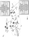
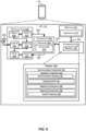
- an example of a wireless communication network 100 including at least one UE 110 and at least one base station 105.
- the UE 110 may include a modem 140 having a synchronization component 150 configured to perform frequency scanning by decoupling of a synchronization channel raster 174 and a channel raster 176.
- the wireless communication network 100 includes at least one base station 105 with a modem 160 having a configuration component 170 configured to transmit one or more synchronization signals 178 and a PBCH 180.
- the base station 105 and/or configuration component 170 may include a determination component 172 configured to determine a synchronization channel raster 174 corresponding to a set of frequencies.
- determination component 172 may determine the synchronization channel raster 174 based at least on a least common multiple (LCM) of a channel raster 176 and a reference resource block (RB) bandwidth.
- LCM least common multiple
- RB reference resource block
- a master information block (MIB) 182 of the PBCH 180 includes a first portion of bits indicating a common control subband for carrying minimum system information block (MSIB) scheduling information.
- the common control subband may correspond to a common search space of a physical downlink control channel (PDCCH).
- the MSIB scheduling information may include at least one of a location information corresponding to a frequency of the set of frequencies of the synchronization channel raster 174 where the one or more synchronization signals are transmitted, a numerology, and a bandwidth.
- the MIB includes a second portion of bits indicating a location of a center frequency 184.
- a first portion of bits of a MIB 182 of the PBCH 180 indicate a location of the center frequency 184 of the bandwidth in relation to a location of the frequency of the set of frequencies of the synchronization channel raster 174.
- the MIB 182 includes a common control subband for carrying MSIB scheduling information.
- the common control subband may be symmetrically located to the center frequency 184 of the bandwidth.
- the common control subband may correspond to a common search space PDCCH.
- the MIB 182 may include a common control subband bandwidth and a common control subband numerology.
- the MIB 182 includes a common control subband for carrying MSIB scheduling information.
- the common control subband may be symmetrically located at any frequency of the bandwidth.
- a second portion of bits of the MIB 182 indicates at least one of a location of the common control subband in relation to a location of the frequency of the set of frequencies of the synchronization channel raster 174, a common control subband bandwidth, and a common control subband numerology.
- the common control subband may correspond to a common search space of the PDCCH.
- the base station 105 and/or configuration component 170 may transmit one or more synchronization signals 178 and a PBCH 180 in any frequency of the set of frequencies of the synchronization channel raster 174 to at least one UE 110.
- the base station 105 and/or configuration component 170 may transmit one or more synchronization signals 178 and a PBCH 180 in a frequency of the set of frequencies of the synchronization channel raster 174 closest to a center frequency 184 of a bandwidth to at least one UE 110.
- the UE 110 and/or synchronization component 150 may include a detection component 152, which may be configured to detect one or more synchronization signals 178 for timing and frequency synchronization with a network entity and a physical cell ID 154 for each frequency of a synchronization channel raster 174.
- the synchronization channel raster corresponds to a LCM of a channel raster 176 and a reference RB bandwidth.
- the UE 110 and/or synchronization component 150 may include a retrieving component 156 configured to retrieve a MIB 182 by decoding a PBCH 180 transmitted from the base station 105.
- the MIB 182 includes a first portion of bits indicating a common control subband for carrying MSIB scheduling information.
- the common control subband corresponds to a common search space of the PDCCH.
- the MSIB scheduling information includes at least one of a location information corresponding to a frequency of the set of frequencies of the synchronization channel raster 174 where the one or more synchronization signals are transmitted, a numerology, and a bandwidth.
- the MIB 182 includes a second portion of bits indicating a location of the center frequency 184.
- the UE 110 and/or synchronization component 150 may include a searching component 158, which may be configured to search for a center frequency 184 based at least on detecting the one or more synchronization signals 178 and retrieving the MIB 182.
- the wireless communication network 100 may include one or more base stations 105, one or more UEs 110, and a core network 115.
- the core network 115 may provide user authentication, access authorization, tracking, internet protocol (IP) connectivity, and other access, routing, or mobility functions.
- IP internet protocol
- the base stations 105 may interface with the core network 115 through backhaul links 120 (e.g., S1, etc.).
- the base stations 105 may perform radio configuration and scheduling for communication with the UEs 110, or may operate under the control of a base station controller (not shown).
- the base stations 105 may communicate, either directly or indirectly (e.g., through core network 115), with one another over backhaul links 125 (e.g., X1, etc.), which may be wired or wireless communication links.
- backhaul links 125 e.g., X1, etc.
- the base stations 105 may wirelessly communicate with the UEs 110 via one or more base station antennas. Each of the base stations 105 may provide communication coverage for a respective geographic coverage area 130.
- the base stations 105 may be referred to as a base transceiver station, a radio base station, an access point, an access node, a radio transceiver, a NodeB, eNodeB (eNB), gNodeB (gNB), Home NodeB, a Home eNodeB, a relay, or some other suitable terminology.
- the geographic coverage area 130 for a base station 105 may be divided into sectors or cells making up only a portion of the coverage area (not shown).
- the wireless communication network 100 may include base stations 105 of different types (e.g., macro base stations or small cell base stations, described below). Additionally, the plurality of base stations 105 may operate according to different ones of a plurality of communication technologies (e.g., 5G (New Radio or "NR"), fourth generation (4G)/LTE, 3G, Wi-Fi, Bluetooth, etc.), and thus there may be overlapping geographic coverage areas 130 for different communication technologies.
- 5G New Radio or "NR”
- 4G fourth generation
- 3G Third Generation
- Wi-Fi Wi-Fi
- the wireless communication network 100 may be or include one or any combination of communication technologies, including a new radio (NR) or 5G technology, a Long Term Evolution (LTE) or LTE-Advanced (LTE-A) or MuLTEfire technology, a Wi-Fi technology, a Bluetooth technology, or any other long or short range wireless communication technology.
- LTE/LTE-A/MuLTEfire networks the term evolved node B (eNB) may be generally used to describe the base stations 105, while the term UE may be generally used to describe the UEs 110.
- the wireless communication network 100 may be a heterogeneous technology network in which different types of eNBs provide coverage for various geographical regions.
- each eNB or base station 105 may provide communication coverage for a macro cell, a small cell, or other types of cell.
- the term "cell” is a 3GPP term that can be used to describe a base station, a carrier or component carrier associated with a base station, or a coverage area (e.g., sector, etc.) of a carrier or base station, depending on context.
- a macro cell may generally cover a relatively large geographic area (e.g., several kilometers in radius) and may allow unrestricted access by the UEs 110 with service subscriptions with the network provider.
- a small cell may include a relative lower transmit-powered base station, as compared with a macro cell, that may operate in the same or different frequency bands (e.g., licensed, unlicensed, etc.) as macro cells.
- Small cells may include pico cells, femto cells, and micro cells according to various examples.
- a pico cell for example, may cover a small geographic area and may allow unrestricted access by the UEs 110 with service subscriptions with the network provider.
- a femto cell may also cover a small geographic area (e.g., a home) and may provide restricted access and/or unrestricted access by the UEs 110 having an association with the femto cell (e.g., in the restricted access case, the UEs 110 in a closed subscriber group (CSG) of the base station 105, which may include the UEs 110 for users in the home, and the like).
- a micro cell may cover a geographic area larger than a pico cell and a femto cell, but smaller than a macro cell.
- An eNB for a macro cell may be referred to as a macro eNB.
- An eNB for a small cell may be referred to as a small cell eNB, a pico eNB, a femto eNB, or a home eNB.
- An eNB may support one or multiple (e.g., two, three, four, and the like) cells (e.g., component carriers).
- the communication networks may be packet-based networks that operate according to a layered protocol stack and data in the user plane may be based on the IP.
- a user plane protocol stack e.g., packet data convergence protocol (PDCP), radio link control (RLC), MAC, etc.
- PDCP packet data convergence protocol
- RLC radio link control
- MAC MAC
- HARQ hybrid automatic repeat/request
- the RRC protocol layer may provide establishment, configuration, and maintenance of an RRC connection between a UE 110 and the base station 105.
- the RRC protocol layer may also be used for core network 115 support of radio bearers for the user plane data.
- the transport channels may be mapped to physical channels.
- the UEs 110 may be dispersed throughout the wireless communication network 100, and each UE 110 may be stationary or mobile.
- a UE 110 may also include or be referred to by those skilled in the art as a mobile station, a subscriber station, a mobile unit, a subscriber unit, a wireless unit, a remote unit, a mobile device, a wireless device, a wireless communications device, a remote device, a mobile subscriber station, an access terminal, a mobile terminal, a wireless terminal, a remote terminal, a handset, a user agent, a mobile client, a client, or some other suitable terminology.
- a UE 110 may be a cellular phone, a smart phone, a personal digital assistant (PDA), a wireless modem, a wireless communication device, a handheld device, a tablet computer, a laptop computer, a cordless phone, a smart watch, a wireless local loop (WLL) station, an entertainment device, a vehicular component, a customer premises equipment (CPE), or any device capable of communicating in wireless communication network 100.
- a UE 110 may be Internet of Things (IoT) and/or machine-to-machine (M2M) type of device, e.g., a low power, low data rate (relative to a wireless phone, for example) type of device, that may in some aspects communicate infrequently with wireless communication network 100 or other UEs.
- a UE 110 may be able to communicate with various types of base stations 105 and network equipment including macro eNBs, small cell eNBs, macro gNBs, small cell gNBs, relay base stations, and the like.
- the UE 110 may be configured to establish one or more wireless communication links 135 with one or more base stations 105.
- the wireless communication links 135 shown in wireless communication network 100 may carry uplink (UL) transmissions from a UE 110 to a base station 105, or downlink (DL) transmissions, from a base station 105 to a UE 110.
- the downlink transmissions may also be called forward link transmissions while the uplink transmissions may also be called reverse link transmissions.
- Each wireless communication link 135 may include one or more carriers, where each carrier may be a signal made up of multiple subcarriers (e.g., waveform signals of different frequencies) modulated according to the various radio technologies described above.
- Each modulated signal may be sent on a different sub-carrier and may carry control information (e.g., reference signals, control channels, etc.), overhead information, user data, etc.
- the wireless communication links 135 may transmit bidirectional communications using frequency division duplex (FDD) (e.g., using paired spectrum resources) or time division duplex (TDD) operation (e.g., using unpaired spectrum resources).
- FDD frequency division duplex
- TDD time division duplex
- Frame structures may be defined for FDD (e.g., frame structure type 1) and TDD (e.g., frame structure type 2).
- the wireless communication links 135 may represent one or more broadcast channels.
- base stations 105 or UEs 110 may include multiple antennas for employing antenna diversity schemes to improve communication quality and reliability between base stations 105 and UEs 110. Additionally or alternatively, base stations 105 or UEs 110 may employ multiple input multiple output (MIMO) techniques that may take advantage of multipath environments to transmit multiple spatial layers carrying the same or different coded data.
- MIMO multiple input multiple output
- Wireless communication network 100 may support operation on multiple cells or carriers, a feature which may be referred to as carrier aggregation (CA) or multicarrier operation.
- a carrier may also be referred to as a component carrier (CC), a layer, a channel, etc.
- CC component carrier
- the terms “carrier,” “component carrier,” “cell,” and “channel” may be used interchangeably herein.
- a UE 110 may be configured with multiple downlink CCs and one or more uplink CCs for carrier aggregation.
- Carrier aggregation may be used with both FDD and TDD component carriers.
- the carriers may or may not be adjacent to each other. Allocation of carriers may be asymmetric with respect to DL and UL (e.g., more or less carriers may be allocated for DL than for UL).
- the component carriers may include a primary component carrier and one or more secondary component carriers.
- a primary component carrier may be referred to as a primary cell (PCell) and a secondary component carrier may be referred to as a secondary cell (SCell).
- PCell primary cell
- SCell secondary cell
- the wireless communications network 100 may further include base stations 105 operating according to Wi-Fi technology, e.g., Wi-Fi access points, in communication with UEs 110 operating according to Wi-Fi technology, e.g., Wi-Fi stations (STAs) via communication links in an unlicensed frequency spectrum (e.g., 5 GHz).
- base stations 105 operating according to Wi-Fi technology
- UEs 110 operating according to Wi-Fi technology
- Wi-Fi stations e.g., Wi-Fi stations (STAs) via communication links in an unlicensed frequency spectrum (e.g., 5 GHz).
- the STAs and AP may perform a clear channel assessment (CCA) or listen before talk (LBT) procedure prior to communicating in order to determine whether the channel is available.
- CCA clear channel assessment
- LBT listen before talk
- one or more of base stations 105 and/or UEs 110 may operate according to a NR or 5G technology referred to as millimeter wave (mmW or mmwave or MMW) technology.
- mmW technology includes transmissions in mmW frequencies and/or near mmW frequencies.
- Extremely high frequency (EHF) is part of the radio frequency (RF) in the electromagnetic spectrum.
- EHF has a range of 30 GHz to 300 GHz and a wavelength between 1 millimeter and 10 millimeters. Radio waves in this band may be referred to as a millimeter wave.
- Near mmW may extend down to a frequency of 3 GHz with a wavelength of 100 millimeters.
- the super high frequency (SHF) band extends between 3 GHz and 30 GHz, and may also be referred to as centimeter wave.
- Communications using the mmW and/or near mmW radio frequency band has extremely high path loss and a short range.
- base stations 105 and/or UEs 110 operating according to the mmW technology may utilize beamforming in their transmissions to compensate for the extremely high path loss and short range.
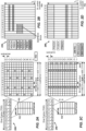
- FIG. 2A is a diagram 200 illustrating an example of a DL subframe within a 5G/NR frame structure.
- FIG. 2B is a diagram 230 illustrating an example of channels within a DL subframe.
- FIG. 2C is a diagram 250 illustrating an example of an UL subframe within a 5G/NR frame structure.
- FIG. 2D is a diagram 280 illustrating an example of channels within an UL subframe.
- the 5G/NR frame structure may be FDD in which for a particular set of subcarriers (carrier system bandwidth), subframes within the set of subcarriers are dedicated for either DL or UL, or may be TDD in which for a particular set of subcarriers (carrier system bandwidth), subframes within the set of subcarriers are dedicated for both DL and UL.
- the 5G/NR frame structure is assumed to be TDD, with subframe 4 a DL subframe and subframe 7 an UL subframe. While subframe 4 is illustrated as providing just DL and subframe 7 is illustrated as providing just UL, any particular subframe may be split into different subsets that provide both UL and DL. Note that the description infra applies also to a 5G/NR frame structure that is FDD.
- a frame (10 ms) may be divided into 10 equally sized subframes (1 ms). Each subframe may include one or more time slots. Each slot may include 7 or 14 symbols, depending on the slot configuration. For slot configuration 0, each slot may include 14 symbols, and for slot configuration 1, each slot may include 7 symbols.
- the number of slots within a subframe is based on the slot configuration and the numerology. For slot configuration 0, different numerologies 0 to 5 allow for 1, 2, 4, 8, 16, and 32 slots, respectively, per subframe. For slot configuration 1, different numerologies 0 to 2 allow for 2, 4, and 8 slots, respectively, per subframe.
- the subcarrier spacing and symbol length/duration are a function of the numerology.
- the subcarrier spacing may be equal to 2 ⁇ ⁇ 15 kKz, where ⁇ is the numerology 0-5.
- the symbol length/duration is inversely related to the subcarrier spacing.
- FIGs. 2A, 2C provide an example of slot configuration 1 with 7 symbols per slot and numerology 0 with 2 slots per subframe.
- the subcarrier spacing is 15 kHz and symbol duration is approximately 66.7 ⁇ s.
- a resource grid may be used to represent the frame structure.
- Each time slot includes a resource block (RB) (also referred to as physical RBs (PRBs)) that extends 12 consecutive subcarriers.
- RB resource block
- PRBs physical RBs
- the resource grid is divided into multiple resource elements (REs). The number of bits carried by each RE depends on the modulation scheme.
- the RS may include demodulation RS (DM-RS) and channel state information reference signals (CSI-RS) for channel estimation at the UE.
- DM-RS demodulation RS
- CSI-RS channel state information reference signals
- the RS may also include beam measurement RS (BRS), beam refinement RS (BRRS), and phase tracking RS (PT-RS).
- BRS beam measurement RS
- BRRS beam refinement RS
- PT-RS phase tracking RS
- FIG. 2B illustrates an example of various channels within a DL subframe of a frame.
- the physical control format indicator channel (PCFICH) is within symbol 0 of slot 0, and carries a control format indicator (CFI) that indicates whether the physical downlink control channel (PDCCH) occupies 1, 2, or 3 symbols ( FIG. 2B illustrates a PDCCH that occupies 3 symbols).
- the PDCCH carries downlink control information (DCI) within one or more control channel elements (CCEs), each CCE including nine RE groups (REGs), each REG including four consecutive REs in an OFDM symbol.
- DCI downlink control information
- CCEs control channel elements
- REGs RE groups
- a UE may be configured with a UE-specific enhanced PDCCH (ePDCCH) that also carries DCI.
- ePDCCH UE-specific enhanced PDCCH
- the ePDCCH may have 2, 4, or 8 RB pairs ( FIG. 2B shows two RB pairs, each subset including one RB pair).
- the physical hybrid automatic repeat request (ARQ) (HARQ) indicator channel (PHICH) is also within symbol 0 of slot 0 and carries the HARQ indicator (HI) that indicates HARQ acknowledgement (ACK) / negative ACK (NACK) feedback based on the physical uplink shared channel (PUSCH).
- the primary synchronization channel (PSCH) may be within symbol 6 of slot 0 within subframes 0 and 5 of a frame.
- the PSCH carries a primary synchronization signal (PSS) that is used by a UE 104 to determine subframe/symbol timing and a physical layer identity.
- PSS primary synchronization signal
- the secondary synchronization channel may be within symbol 5 of slot 0 within subframes 0 and 5 of a frame.
- the SSCH carries a secondary synchronization signal (SSS) that is used by a UE to determine a physical layer cell identity group number and radio frame timing. Based on the physical layer identity and the physical layer cell identity group number, the UE can determine a physical cell identifier (PCI). Based on the PCI, the UE can determine the locations of the aforementioned DL-RS.
- the physical broadcast channel (PBCH) which carries a master information block (MIB), may be logically grouped with the PSCH and SSCH to form a synchronization signal (SS)/PBCH block.
- MIB master information block
- the MIB provides a number of RBs in the DL system bandwidth, a PHICH configuration, and a system frame number (SFN).
- the physical downlink shared channel (PDSCH) carries user data, broadcast system information not transmitted through the PBCH such as system information blocks (SIBs), and paging messages.
- SIBs system information blocks
- some of the REs carry demodulation reference signals (DM-RS) for channel estimation at the base station.
- the UE may additionally transmit sounding reference signals (SRS) in the last symbol of a subframe.
- SRS may have a comb structure, and a UE may transmit SRS on one of the combs.
- the SRS may be used by a base station for channel quality estimation to enable frequency-dependent scheduling on the UL.
- FIG. 2D illustrates an example of various channels within an UL subframe of a frame.
- a physical random access channel PRACH
- the PRACH may be within one or more subframes within a frame based on the PRACH configuration.
- the PRACH may include six consecutive RB pairs within a subframe.
- the PRACH allows the UE to perform initial system access and achieve UL synchronization.
- a physical uplink control channel PUCCH may be located on edges of the UL system bandwidth.
- the PUCCH carries uplink control information (UCI), such as scheduling requests, a channel quality indicator (CQI), a precoding matrix indicator (PMI), a rank indicator (RI), and HARQ ACK/NACK feedback.
- the PUSCH carries data, and may additionally be used to carry a buffer status report (BSR), a power headroom report (PHR), and/or UCI.
- BSR buffer status report
- PHR power headroom report
- a method 300 of wireless communication at the base station 105 includes one or more of the herein-defined actions.
- the method 300 may determine, at a network entity, a synchronization channel raster corresponding to a set of frequencies.
- the base station 105 and/or the configuration component 170 may execute the determination component 172 to determine a synchronization channel raster 174 corresponding to a set of frequencies.
- the determination component 172 may determine the synchronization channel raster 174 based at least on a LCM of a channel raster 176 and a reference RB bandwidth.
- the determination component 172 may configure a channel raster 176 to 100 kHz, with a reference RB bandwidth of 180 kHz.
- the method 300 may transmit, from the network entity, one or more synchronization signals and a PBCH in any frequency of the set of frequencies of the synchronization channel raster to at least one UE.
- the base station 105 and/or the configuration component 170 may transmit one or more synchronization signals 178 and a PBCH 180 in any frequency of the set of frequencies of the synchronization channel raster 174 to at least one UE 110.
- the base station 105 and/or the configuration component 170 may transmit one or more synchronization signals 178 (e.g., primary and secondary synchronization signals) and a PBCH 180 in any multiple of a frequency of the synchronization channel raster 174 (e.g., 1.8 MHz, 3.6 MHz, etc.) to one or more UEs, e.g., UE 110.
- synchronization signals 178 e.g., primary and secondary synchronization signals
- a PBCH 180 in any multiple of a frequency of the synchronization channel raster 174 (e.g., 1.8 MHz, 3.6 MHz, etc.) to one or more UEs, e.g., UE 110.
- the base station 105 and/or the configuration component 170 may transmit the synchronization signals 178 and the PBCH 180 in any synchronization channel raster frequency (i.e., any multiple of the synchronization channel raster 174).
- a number of bits (e.g., "X" number of bits) of a MIB 182 may be used to indicate common control sub-band (e.g., common search space PDCCH) which carries a MSIB scheduling, for example, location with respect to the synchronization channel raster frequency where synchronization signals 178 are transmitted, numerology (e.g., subcarrier spacing, symbol times, FFT sizes, etc.), and bandwidth.
- numerology e.g., subcarrier spacing, symbol times, FFT sizes, etc.
- the "Y" bits of the MSIB may be used to indicate the center frequency 184 location.
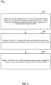
- a method 400 of wireless communication at the UE 110 includes one or more of the herein-defined actions.
- the method 400 may detect, at a UE, one or more synchronization signals for timing and frequency synchronization with a network entity and a physical cell ID for each frequency of a synchronization channel raster.
- the UE 110 and/or the synchronization component 150 may execute the detection component 152 to detect one or more synchronization signals 178 for timing and frequency synchronization with a base station 105 and a physical cell ID 154 for each frequency of a synchronization channel raster 174.
- the physical cell ID 154 may have a range of 0 to 503 and may be used to scramble the data so that the UE 110 may separate information from the different transmitters.
- a physical cell ID 154 may determine the primary and secondary synchronization signal sequence transmitted from the base station 105.
- the method 400 may retrieve, at the UE, a MIB by decoding a PBCH transmitted from the network entity.
- the UE 110 and/or the synchronization component 150 may execute the retrieving component 156 to retrieve a MIB 182 by decoding a PBCH 180 transmitted from the base station 105.
- the method 400 may search, by the UE, for a center frequency based at least on detecting the one or more synchronization signals and retrieving the MIB.
- the UE 110 and/or the synchronization component 150 may execute the searching component 158 to search for a center frequency 184 based at least on detecting the one or more synchronization signals 178 and retrieving the MIB 182.
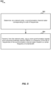
- a method 500 of wireless communication at the base station 105 includes one or more of the herein-defined actions.
- the method 300 may determine, at a network entity, a synchronization channel raster corresponding to a set of frequencies.
- the base station 105 and/or the configuration component 170 may execute the determination component 172 to determine a synchronization channel raster 174 corresponding to a set of frequencies.
- the determination component 172 may configure a channel raster 176 to 100 kHz, with a reference RB bandwidth of 180 kHz.
- the determination component 172 may determine the synchronization channel raster 174 as a multiple of LCM of the channel raster 176 and the reference RB bandwidth.
- the method 500 may transmit, from the network entity, one or more synchronization signals and a PBCH in a frequency of the set of frequencies of the synchronization channel raster closest to a center frequency of a bandwidth to at least one UE.
- the base station 105 and/or the configuration component 170 may transmit one or more synchronization signals 178 and a PBCH 180 in a frequency of the set of frequencies of the synchronization channel raster 174 closest to a center frequency 184 of a bandwidth to at least one UE 110.
- the synchronization signals 178 and the PBCH 180 may be transmitted in the synchronization channel raster frequency closest to the center frequency 184.
- a number of bits (e.g., "X" number of bits) in the MIB 182 may be used to indicate the center frequency 184 location with respect to the synchronization channel raster frequency where synchronization signals 178 are transmitted. For example, if the synchronization channel raster 174 is 1.8 MHz, five bits may be used to signal the center frequency 184 location in steps of the channel raster 176, e.g., 100 kHz.
- common control sub-band e.g., common search space PDCCH
- MSIB scheduling is symmetric around the center frequency 184
- common control sub-band e.g., common search space PDCCH
- bandwidth and numerology may be signaled in the MIB 182.
- the synchronization signals 178 and the PBCH 180 may be transmitted in the synchronization channel raster 174 closest to the center frequency 184.
- a number of bits (e.g., "X" number of bits) in the MIB 182 may be used to indicate the center frequency 184 location with respect to the synchronization channel raster frequency where synchronization signals 178 are transmitted. For example, if the synchronization channel raster 174 is 1.8 MHz, five bits may be used to signal the center frequency 184 location in steps of the channel raster 176 (e.g., 100 kHz).
- common control sub-band e.g., common search space PDCCH
- MSIB scheduling can be present anywhere in the system bandwidth, and a "Y" number of bits in the MIB 182 may be used to indicate common control sub-band (e.g., search space PDCCH) carrying MSIB scheduling location with respect to the synchronization channel raster frequency where synchronization signals 178 are transmitted, numerology, and bandwidth.
- the synchronization channel raster 174 may be defined as a function of the channel raster 176.
- the channel raster 176 is for the center frequency 184 placement and signaling granularity of the synchronization channel raster offset to the center frequency 184.
- the channel raster 176 may be assumed to be 100 kHz (similar to LTE).
- the synchronization channel raster 174 may be signaled by steps of the channel raster 176.
- the synchronization channel raster 174 is 1.8 MHz and the channel raster 176 is 100 kHz, 5 bits are needed for synchronization raster offset to the center frequency 184, and the synchronization signals 178 are transmitted in the synchronization channel raster point closest to the center frequency 184 to minimize signaling of the synchronization offset to the center frequency 184.
- a guard around the synchronization channel raster 174 may be needed to minimize interference.
- the guard may be dimensioned in neighboring RBs used for data or control channels. That is, data may be only mapped into the upper half of the edge data RB.
- the guard may be dimensioned in edge synchronization tones of the edge sync RBs. For instance, 7 RBs (2.52 MHz) may be required and 72 middle tones may be used for synchronization. The number of left-over tones in fractional neighboring data RBs on tone spacing of such RBs.
- SCC subcarrier spacing
- TDM time division multiplexing
- the UE 110 may assume the frequency location of the synchronization signal(s) among neighbor cells and the UE 110 may also assume that the neighbor cells may have measurement signals of minimum bandwidth or synchronization bandwidth. Additionally, the UE 110 may assume that neighbor cells may have measurements signals of minimum bandwidth or synchronization bandwidth, or the base station 105 may signal the measurement signal bandwidth of the inter-frequency neighbor cells.
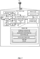
- an UE 110 may include a variety of components, some of which have already been described above, but including components such as one or more processors 612 and memory 616 and transceiver 602 in communication via one or more buses 644, which may operate in conjunction with modem 140 and synchronization component 150. Further, the one or more processors 612, modem 140, memory 616, transceiver 602, radio frequency (RF) front end 688 and one or more antennas 665, may be configured to support voice and/or data calls (simultaneously or non-simultaneously) in one or more radio access technologies. In some aspects, the modem 140 may be the same as or similar to the modem 140 ( FIG. 1 ).
- the one or more processors 612 can include a modem 140 that uses one or more modem processors.
- the various functions related to synchronization component 150 may be included in modem 140 and/or processors 612 and, in an aspect, can be executed by a single processor, while in other aspects, different ones of the functions may be executed by a combination of two or more different processors.
- the one or more processors 612 may include any one or any combination of a modem processor, or a baseband processor, or a digital signal processor, or a transmit processor, or a receiver processor, or a transceiver processor associated with transceiver 602. In other aspects, some of the features of the one or more processors 612 and/or modem 140 associated with synchronization component 150 may be performed by transceiver 602.
- the memory 616 may be configured to store data used herein and/or local versions of applications 675 or synchronization component 150 and/or one or more of its subcomponents being executed by at least one processor 612.
- Memory 616 can include any type of computer-readable medium usable by a computer or at least one processor 612, such as random access memory (RAM), read only memory (ROM), tapes, magnetic discs, optical discs, volatile memory, non-volatile memory, and any combination thereof.
- memory 616 may be a non-transitory computer-readable storage medium that stores one or more computer-executable codes defining synchronization component 150 and/or one or more of its subcomponents, and/or data associated therewith, when UE 110 is operating at least one processor 612 to execute synchronization component 150 and/or one or more of its subcomponents.
- the transceiver 602 may include at least one receiver 606 and at least one transmitter 608.
- the receiver 606 may include hardware, firmware, and/or software code executable by a processor for receiving data, the code comprising instructions and being stored in a memory (e.g., computer-readable medium).
- the receiver 606 may be, for example, a RF receiver.
- the receiver 606 may receive signals transmitted by at least one base station 105. Additionally, the receiver 606 may process such received signals, and also may obtain measurements of the signals, such as, but not limited to, Ec/Io, SNR, RSRP, RSSI, etc.
- the transmitter 608 may include hardware, firmware, and/or software code executable by a processor for transmitting data, the code comprising instructions and being stored in a memory (e.g., computer-readable medium).
- a suitable example of the transmitter 608 may include , but is not limited to, an RF transmitter.
- the UE 110 may include the RF front end 688, which may operate in communication with one or more antennas 665 and transceiver 602 for receiving and transmitting radio transmissions, for example, wireless communications transmitted by at least one base station 105 or wireless transmissions transmitted by the UE 110.
- the RF front end 688 may be coupled with one or more antennas 665 and can include one or more low-noise amplifiers (LNAs) 690, one or more switches 692, one or more power amplifiers (PAs) 698, and one or more filters 696 for transmitting and receiving RF signals.
- LNAs low-noise amplifiers
- PAs power amplifiers
- the LNA 690 can amplify a received signal at a desired output level.
- each LNA 690 may have a specified minimum and maximum gain values.
- the RF front end 688 may use one or more switches 692 to select a particular LNA 690 and a specified gain value based on a desired gain value for a particular application.
- the one or more PA(s) 698 may be used by the RF front end 688 to amplify a signal for an RF output at a desired output power level.
- each PA 698 may have specified minimum and maximum gain values.
- the RF front end 688 may use one or more switches 692 to select a particular PA 698 and a corresponding specified gain value based on a desired gain value for a particular application.
- the one or more filters 696 can be used by the RF front end 688 to filter a received signal to obtain an input RF signal.
- a respective filter 696 can be used to filter an output from a respective PA 698 to produce an output signal for transmission.
- each filter 696 can be coupled with a specific LNA 690 and/or PA 698.
- the RF front end 688 can use one or more switches 692 to select a transmit or receive path using a specified filter 696, LNA 690, and/or PA 698, based on a configuration as specified by transceiver 602 and/or processor 612.
- the transceiver 602 may be configured to transmit and receive wireless signals through one or more antennas 665 via the RF front end 688.
- transceiver 602 may be tuned to operate at specified frequencies such that the UE 110 can communicate with, for example, the one or more base stations 65 or one or more cells associated with one or more base stations 65.
- the modem 140 can configure the transceiver 602 to operate at a specified frequency and power level based on the UE configuration of the UE 110 and the communication protocol used by the modem 140.
- the modem 140 can be a multiband-multimode modem, which can process digital data and communicate with the transceiver 602 such that the digital data is sent and received using the transceiver 602.
- the modem 140 can be multiband and be configured to support multiple frequency bands for a specific communications protocol.
- the modem 140 can be multimode and be configured to support multiple operating networks and communications protocols.
- the modem 140 can control one or more components of the UE 110 (e.g., RF front end 688, transceiver 602) to enable transmission and/or reception of signals from the network based on a specified modem configuration.
- the modem configuration can be based on the mode of the modem and the frequency band in use.
- the modem configuration can be based on UE configuration information associated with the UE 110 as provided by the network during cell selection and/or cell reselection.
- base station 105 may include a variety of components, some of which have already been described above, but including components such as one or more processors 712, a memory 716, and a transceiver 702 in communication via one or more buses 744, which may operate in conjunction with the modem 160 and configuration component 170 to enable one or more of the functions described herein.
- components such as one or more processors 712, a memory 716, and a transceiver 702 in communication via one or more buses 744, which may operate in conjunction with the modem 160 and configuration component 170 to enable one or more of the functions described herein.
- the transceiver 702, receiver 706, transmitter 708, one or more processors 712, memory 716, applications 775, buses 744, RF front end 788, LNAs 790, switches 792, filters 796, PAs 798, and one or more antennas 765 may be the same as or similar to the corresponding components of UE 110, as described above, but configured or otherwise programmed for base station operations as opposed to UE operations.
- Information and signals may be represented using any of a variety of different technologies and techniques.
- data, instructions, commands, information, signals, bits, symbols, and chips that may be referenced throughout the above description may be represented by voltages, currents, electromagnetic waves, magnetic fields or particles, optical fields or particles, computer-executable code or instructions stored on a computer-readable medium, or any combination thereof.
- a specially-programmed device such as but not limited to a processor, a digital signal processor (DSP), an ASIC, a FPGA or other programmable logic device, a discrete gate or transistor logic, a discrete hardware component, or any combination thereof designed to perform the functions described herein.
- DSP digital signal processor
- a specially-programmed processor may be a microprocessor, but in the alternative, the processor may be any conventional processor, controller, microcontroller, or state machine.
- a specially-programmed processor may also be implemented as a combination of computing devices, e.g., a combination of a DSP and a microprocessor, multiple microprocessors, one or more microprocessors in conjunction with a DSP core, or any other such configuration.
- the functions described herein may be implemented in hardware, software executed by a processor, firmware, or any combination thereof. If implemented in software executed by a processor, the functions may be stored on or transmitted over as one or more instructions or code on a non-transitory computer-readable medium. For example, due to the nature of software, functions described above can be implemented using software executed by a specially programmed processor, hardware, firmware, hardwiring, or combinations of any of these. Features implementing functions may also be physically located at various positions, including being distributed such that portions of functions are implemented at different physical locations.
- Computer-readable media includes both computer storage media and communication media including any medium that facilitates transfer of a computer program from one place to another.
- a storage medium may be any available medium that can be accessed by a general purpose or special purpose computer.
- computer-readable media can comprise RAM, ROM, EEPROM, CD-ROM or other optical disk storage, magnetic disk storage or other magnetic storage devices, or any other medium that can be used to carry or store desired program code means in the form of instructions or data structures and that can be accessed by a general-purpose or special-purpose computer, or a general-purpose or special-purpose processor.
- any connection is properly termed a computer-readable medium.
- Disk and disc include compact disc (CD), laser disc, optical disc, digital versatile disc (DVD), floppy disk and Blu-ray disc where disks usually reproduce data magnetically, while discs reproduce data optically with lasers. Combinations of the above are also included within the scope of computer-readable media.
Description
- The present Application for Patent claims priority to
U.S. Non-Provisional Application No. 15/802,181 entitled "DECOUPLING OF SYNCHRONIZATION RASTER AND CHANNEL RASTER" filed November 2, 2017 U.S. Provisional Application No. 62/417,993 entitled "DECOUPLING OF SYNCHRONIZATION RASTER AND CHANNEL RASTER" filed November 4, 2016 - Aspects of the present disclosure relates generally to communication systems, and more particularly, to decoupling of a synchronization ("sync") channel raster and a channel raster in a wireless communication system.
- Wireless communication systems are widely deployed to provide various telecommunication services such as telephony, video, data, messaging, and broadcasts. Typical wireless communication systems may employ multiple-access technologies capable of supporting communication with multiple users by sharing available system resources (e.g., bandwidth, transmit power). Examples of such multiple-access technologies include code division multiple access (CDMA) systems, wideband CDMA (W-CDMA) systems, time division multiple access (TDMA) systems, frequency division multiple access (FDMA) systems, orthogonal frequency division multiple access (OFDMA) systems, wide band single-carrier frequency division multiple access (SC-FDMA) systems, and time division synchronous code division multiple access (TD-SCDMA) systems.
- These multiple access technologies have been adopted in various telecommunication standards to provide a common protocol that enables different wireless devices to communicate on a municipal, national, regional, and even global level. For example, 5G NR (new radio) communications technology is envisaged to expand and support diverse usage scenarios and applications with respect to current mobile network generations. In an aspect, 5G communications technology includes enhanced mobile broadband addressing human-centric use cases for access to multimedia content, services and data; ultra-reliable-low latency communications (URLLC) with requirements, especially in terms of latency and reliability; and massive machine type communications for a very large number of connected devices, and typically transmitting a relatively low volume of non-delay-sensitive information. However, as the demand for mobile broadband access continues to increase, there exists a need for further improvements in 5G communications technology and beyond. Preferably, these improvements should be applicable to other multi-access technologies and the telecommunication standards that employ these technologies.
- During initial acquisition at a user equipment (LTE) in long term evolution (LTE) networks, the UE performs a frequency scan first. The UE searches for a carrier center frequency by scanning through configured frequency bands. For a given frequency band and a channel raster (e.g., 100 kHz in LTE), the UE may detect a set of center frequency candidates (e.g., by a downlink power spectrum measurement or waveform detection) over which the synchronization signals could be detected. However, such frequency scan procedure has some drawbacks in NR networks. For example, as NR is expected to be deployed in wide frequency bands, frequency scanning using the channel raster is not efficient. Further, there may be confusion between NR/LTE networks, as both NR and LTE employ OFDM based waveforms in the downlink. Furthermore, "alien" waveform confusion may occur when some massive Machine Type Communications (mMTC) waveforms or some on-demand signals exist in the frequency band.
- Therefore, for NR communications technology and beyond (and with Long Term Evolution (LTE communications technology), improvements in decoupling the synchronization channel raster and the channel raster may be desired.
- 3GPP contribution "Channel raster and synchronization signal locations" by Huawei, HiSilicon, TSG RAN WG1 Meeting #86bis, R1-1608847, discusses channel raster design, and mapping of the synchronization signals. It is proposed to use a sparser frequency raster used for synchronization and NR cell search than for carrier/channel raster used for placing the center of a NR carrier.
- 3GPP contribution "Single beam synchronization design" by Qualcomm Incorporated, TSG RAN WG1 Meeting #86b, R1-1610156, discusses various aspects of the NR synchronization, including synchronization raster design and synchronization signal design.
- 3GPP contribution "DL control channels overview" by Qualcomm Incorporated, TSG RAN WG1 Meeting #86bis, R1-1610177, provides an overview on DL control channels for NR and a discussion for PDCCH.
- The invention is defined in the appended claims. The following presents a simplified summary of one or more aspects in order to provide a basic understanding of such aspects. This summary is not an extensive overview of all contemplated aspects, and is intended to neither identify key or critical elements of all aspects nor delineate the scope of any or all aspects. Its sole purpose is to present some concepts of one or more aspects in a simplified form as a prelude to the more detailed description that is presented later.
- In accordance with an aspect, a method for decoupling of a synchronization channel raster and a channel raster for wireless communications. The described aspects include determining, at a network entity, a synchronization channel raster corresponding to a set of frequencies. The described aspects further include transmitting, from the network entity, one or more synchronization signals and a physical broadcast channel (PBCH) in any frequency of the set of frequencies of the synchronization channel raster to at least one user equipment (UE).
- In an aspect, an apparatus, such as a network entity, for decoupling of a synchronization channel raster and a channel raster for wireless communications may include a transceiver, a memory, and at least one processor coupled with the memory and configured to determine, at the network entity, a synchronization channel raster corresponding to a set of frequencies. The described aspects further transmit, from the network entity, one or more synchronization signals and a PBCH in any frequency of the set of frequencies of the synchronization channel raster to at least one UE.
- In an aspect, a computer-readable medium may store computer executable code for decoupling of a synchronization channel raster and a channel raster for wireless communications is described. The described aspects include code for determining, at a network entity, a synchronization channel raster corresponding to a set of frequencies. The described aspects further include code for transmitting, from the network entity, one or more synchronization signals and a PBCH in any frequency of the set of frequencies of the synchronization channel raster to at least one UE.
- In an aspect, an apparatus for decoupling of a synchronization channel raster and a channel raster for wireless communications is described. The described aspects include means for determining, at a network entity, a synchronization channel raster corresponding to a set of frequencies. The described aspects further include means for transmitting, from the network entity, one or more synchronization signals and a PBCH in any frequency of the set of frequencies of the synchronization channel raster to at least one UE.
- In accordance with an aspect, a method for decoupling of a synchronization channel raster and a channel raster for wireless communications. The described aspects include detecting, at a UE, one or more synchronization signals for timing and frequency synchronization with a network entity and a physical cell identifier (ID) for each frequency of a synchronization channel raster. The described aspects further include retrieving, at the UE, a master information block (MIB) by decoding a PBCH transmitted from the network entity. The described aspects further include searching, by the UE, for a center frequency based at least on detecting the one or more synchronization signals and retrieving the MIB.
- In an aspect, an apparatus, such as a UE, for decoupling of a synchronization channel raster and a channel raster for wireless communications may include a transceiver, a memory, and at least one processor coupled with the memory and configured to detect, at a UE, one or more synchronization signals for a timing and a frequency synchronization with a network entity and a physical cell ID for each frequency of a synchronization channel raster. The described aspects further retrieve, at the UE, a MIB by decoding a PBCH transmitted from the network entity. The described aspects further search, by the UE, for a center frequency based at least on detecting the one or more synchronization signals and retrieving the MIB.
- In an aspect, a computer-readable medium may store computer executable code for decoupling of a synchronization channel raster and a channel raster for wireless communications is described. The described aspects include code for detecting, at a UE, one or more synchronization signals for a timing and a frequency synchronization with a network entity and a physical cell ID for each frequency of a synchronization channel raster. The described aspects further include code for retrieving, at the UE, a MIB by decoding a PBCH transmitted from the network entity. The described aspects further include code for searching, by the UE, for a center frequency based at least on detecting the one or more synchronization signals and retrieving the MIB.
- In an aspect, an apparatus for decoupling of a synchronization channel raster and a channel raster for wireless communications is described. The described aspects include means for detecting, at a UE, one or more synchronization signals for a timing and a frequency synchronization with a network entity and a physical cell ID for each frequency of a synchronization channel raster. The described aspects further include means for retrieving, at the UE, a MIB by decoding a PBCH transmitted from the network entity. The described aspects further include means for searching, by the UE, for a center frequency based at least on detecting the one or more synchronization signals and retrieving the MIB.
- In accordance with an aspect, a method for decoupling of a synchronization channel raster and a channel raster for wireless communications. The described aspects include determining, at a network entity, a synchronization channel raster corresponding to a set of frequencies. The described aspects further include transmitting, from the network entity, one or more synchronization signals and a PBCH in a frequency of the set of frequencies of the synchronization channel raster closest to a center frequency of a bandwidth to at least one UE.
- In an aspect, an apparatus, such as a network entity, for decoupling of a synchronization channel raster and a channel raster for wireless communications may include a transceiver, a memory, and at least one processor coupled with the memory and configured to determine, at the network entity, a synchronization channel raster corresponding to a set of frequencies. The described aspects further transmit, from the network entity, one or more synchronization signals and a PBCH in a frequency of the set of frequencies of the synchronization channel raster closest to a center frequency of a bandwidth to at least one UE.
- In an aspect, a computer-readable medium may store computer executable code for decoupling of a synchronization channel raster and a channel raster for wireless communications is described. The described aspects include code for determining, at a network entity, a synchronization channel raster corresponding to a set of frequencies. The described aspects further include code for transmitting, from the network entity, one or more synchronization signals and a PBCH in a frequency of the set of frequencies of the synchronization channel raster closest to a center frequency of a bandwidth to at least one UE.
- In an aspect, an apparatus for decoupling of a synchronization channel raster and a channel raster for wireless communications is described. The described aspects include means for determining, at a network entity, a synchronization channel raster corresponding to a set of frequencies. The described aspects further include means for transmitting, from the network entity, one or more synchronization signals and a PBCH in a frequency of the set of frequencies of the synchronization channel raster closest to a center frequency of a bandwidth to at least one UE.
- To the accomplishment of the foregoing and related ends, the one or more aspects comprise the features hereinafter fully described and particularly pointed out in the claims. The following description and the annexed drawings set forth in detail certain illustrative features of the one or more aspects. These features are indicative, however, of but a few of the various ways in which the principles of various aspects may be employed, and this description is intended to include all such aspects and their equivalents.
- The disclosed aspects will hereinafter be described in conjunction with the appended drawings, provided to illustrate and not to limit the disclosed aspects, wherein like designations denote like elements, and in which:
-
FIG. 1 is a schematic diagram of an example of a wireless communication network including at least one base station having a configuration component and at least one UE having a synchronization component; -
FIG. 2A is a diagram illustrating an example of a downlink (DL) subframe for a 5G/NR frame structure; -
FIG. 2B is a diagram illustrating an example of a DL channels within the DL subframe for a 5G/NR frame structure; -
FIG. 2C is a diagram illustrating an example of an uplink (UL) subframe for a 5G/NR frame structure; -
FIG. 2D is a diagram illustrating an example of a UL channels within the UL subframe respectively, for a 5G/NR frame structure; -
FIG. 3 is a flow diagram of an example of a method for decoupling of a synchronization channel raster and a channel raster for wireless communications at a network entity; -
FIG. 4 is a flow diagram of an example of a method for decoupling of a synchronization channel raster and a channel raster for wireless communications at a UE; -
FIG. 5 is a flow diagram of another example of a method for decoupling of a synchronization channel raster and a channel raster for wireless communications at a network entity; -
FIG. 6 is a schematic diagram of example components of the UE ofFIG. 1 ; and -
FIG. 7 is a schematic diagram of example components of the base station ofFIG. 1 . - The detailed description set forth below in connection with the appended drawings is intended as a description of various configurations and is not intended to represent the only configurations in which the concepts described herein may be practiced. The detailed description includes specific details for the purpose of providing a thorough understanding of various concepts. However, it will be apparent to those skilled in the art that these concepts may be practiced without these specific details. In some instances, well known components are shown in block diagram form in order to avoid obscuring such concepts.
- The present disclosure provides an example method and apparatus for decoupling of a synchronization channel raster and a channel raster for wireless communications. For example, during initial acquisition at a UE in LTE networks, the UE initially performs a frequency scan by searching for a carrier center frequency by scanning through configured frequency bands. For a given frequency band and a channel raster (e.g., 100kHz in LTE), the UE may detect a set of center frequency candidates (e.g., by a downlink power spectrum measurement or waveform detection) over which the synchronization signals can be detected. However, such a frequency scan procedure has some drawbacks in NR networks. For example, as NR is expected to be deployed in wide frequency bands, frequency scanning using the channel raster is not efficient. Further, there may be confusion between NR/LTE networks, as both NR and LTE employ OFDM based waveforms in the downlink. Furthermore, "alien" waveform confusion may occur when some massive Machine Type Communications (mMTC) waveforms or some on-demand signals exist in the frequency band.
- The present disclosure introduces an efficient frequency scan procedure by decoupling the channel raster and the synchronization channel raster. In an aspect, a channel raster of 100 kHz indicates that the carrier frequency is a multiple of 100 kHz. Similarly, a synchronization raster of 2 MHz indicates the frequency of the synchronization channel is a multiple of 2 MHz. For example, in an aspect, the channel raster for a NR below 6 GHz ("Sub6") may be similar to LTE channel raster (e.g., 100 kHz) to provide deployment flexibility. The synchronization channel raster is much coarser (e.g., wider in bandwidth) than the channel raster to reduce the complexity of the frequency scan and achieve faster detection. In one implementation, the synchronization channel raster may be a multiple of a least common multiple of the channel raster and reference resource block (RB) bandwidth so as to allow for faster alignment of the synchronization channel raster with both the channel raster and the RB.
- The present disclosure provides an example method and an apparatus for decoupling of a synchronization channel raster and a channel raster that may include determining, at a network entity, a synchronization channel raster corresponding to a set of frequencies, and transmitting, from the network entity, one or more synchronization signals and a PBCH in any frequency of the set of frequencies of the synchronization channel raster to at least one UE. The present disclosure provides another method and apparatus for detecting, at a UE, one or more synchronization signals for timing and frequency synchronization with a network entity and a physical cell identifier (ID) for each frequency of a synchronization channel raster, retrieving, at the UE, a MIB by decoding a PBCH transmitted from the network entity, and searching, by the UE, for a center frequency based at least on detecting the one or more synchronization signals and retrieving the MIB. The present disclosure provides another method and apparatus for determining, at a network entity, a synchronization channel raster corresponding to a set of frequencies, and transmitting, from the network entity, one or more synchronization signals and a PBCH in a frequency of the set of frequencies of the synchronization channel raster closest to a center frequency of a bandwidth to at least one.
- Additional features of the present aspects are described in more detail below with respect to
FIGS. 1-7 . - It should be noted that the techniques described herein may be used for various wireless communication networks such as CDMA, TDMA, FDMA, OFDMA, SC-FDMA, and other systems. The terms "system" and "network" are often used interchangeably. A CDMA system may implement a radio technology such as CDMA2000, Universal Terrestrial Radio Access (UTRA), etc. CDMA2000 covers IS-2000, IS-95, and IS-856 standards. IS-2000
Releases 0 and A are commonly referred to as CDMA2000 1X, 1X, etc. IS-856 (TIA-856) is commonly referred to as CDMA2000 1xEV-DO, High Rate Packet Data (HRPD), etc. UTRA includes Wideband CDMA (WCDMA) and other variants of CDMA. A TDMA system may implement a radio technology such as Global System for Mobile Communications (GSM). An OFDMA system may implement a radio technology such as Ultra Mobile Broadband (UMB), Evolved UTRA (E-UTRA), IEEE 802.11 (Wi-Fi), IEEE 802.16 (WiMAX), IEEE 802.20, Flash-OFDM™, etc. UTRA and E-UTRA are part of Universal Mobile Telecommunication System (UMTS). 3GPP Long Term Evolution (LTE) and LTE-Advanced (LTE-A) are new releases of UMTS that use E-UTRA. UTRA, E-UTRA, UMTS, LTE, LTE-A, and GSM are described in documents from an organization named "3rd Generation Partnership Project" (3GPP). CDMA2000 and UMB are described in documents from an organization named "3rdGeneration Partnership Project 2" (3GPP2). The techniques described herein may be used for the systems and radio technologies mentioned above as well as other systems and radio technologies, including cellular (e.g., LTE) communications over a shared radio frequency spectrum band. The description below, however, describes an LTE/LTE-A system for purposes of example, and LTE terminology is used in much of the description below, although the techniques are applicable beyond LTE/LTE-A applications (e.g., to 5G networks or other next generation communication systems). - The following description provides examples, and is not limiting of the scope, applicability, or examples set forth in the claims. Changes may be made in the function and arrangement of elements discussed without departing from the scope of the disclosure. Various examples may omit, substitute, or add various procedures or components as appropriate. For instance, the methods described may be performed in an order different from that described, and various steps may be added, omitted, or combined. Also, features described with respect to some examples may be combined in other examples.
- Referring to
FIG. 1 , in accordance with various aspects of the present disclosure, an example of awireless communication network 100 including at least oneUE 110 and at least onebase station 105. TheUE 110 may include amodem 140 having asynchronization component 150 configured to perform frequency scanning by decoupling of a synchronization channel raster 174 and achannel raster 176. Further, thewireless communication network 100 includes at least onebase station 105 with amodem 160 having a configuration component 170 configured to transmit one or more synchronization signals 178 and aPBCH 180. - In an aspect, the
base station 105 and/or configuration component 170 may include a determination component 172 configured to determine a synchronization channel raster 174 corresponding to a set of frequencies. For example, determination component 172 may determine the synchronization channel raster 174 based at least on a least common multiple (LCM) of achannel raster 176 and a reference resource block (RB) bandwidth. - In an aspect, a master information block (MIB) 182 of the
PBCH 180 includes a first portion of bits indicating a common control subband for carrying minimum system information block (MSIB) scheduling information. The common control subband may correspond to a common search space of a physical downlink control channel (PDCCH). Further, wherein the MSIB scheduling information may include at least one of a location information corresponding to a frequency of the set of frequencies of the synchronization channel raster 174 where the one or more synchronization signals are transmitted, a numerology, and a bandwidth. In another example, the MIB includes a second portion of bits indicating a location of acenter frequency 184. - In another aspect, a first portion of bits of a
MIB 182 of thePBCH 180 indicate a location of thecenter frequency 184 of the bandwidth in relation to a location of the frequency of the set of frequencies of the synchronization channel raster 174. For example, theMIB 182 includes a common control subband for carrying MSIB scheduling information. The common control subband may be symmetrically located to thecenter frequency 184 of the bandwidth. The common control subband may correspond to a common search space PDCCH. Further, theMIB 182 may include a common control subband bandwidth and a common control subband numerology. - In another aspect, the
MIB 182 includes a common control subband for carrying MSIB scheduling information. For example, the common control subband may be symmetrically located at any frequency of the bandwidth. Further, a second portion of bits of theMIB 182 indicates at least one of a location of the common control subband in relation to a location of the frequency of the set of frequencies of the synchronization channel raster 174, a common control subband bandwidth, and a common control subband numerology. The common control subband may correspond to a common search space of the PDCCH. - In an aspect, the
base station 105 and/or configuration component 170 may transmit one or more synchronization signals 178 and aPBCH 180 in any frequency of the set of frequencies of the synchronization channel raster 174 to at least oneUE 110. - In another aspect, the
base station 105 and/or configuration component 170 may transmit one or more synchronization signals 178 and aPBCH 180 in a frequency of the set of frequencies of the synchronization channel raster 174 closest to acenter frequency 184 of a bandwidth to at least oneUE 110. - In an aspect, the
UE 110 and/orsynchronization component 150 may include a detection component 152, which may be configured to detect one or more synchronization signals 178 for timing and frequency synchronization with a network entity and aphysical cell ID 154 for each frequency of a synchronization channel raster 174. For example, the synchronization channel raster corresponds to a LCM of achannel raster 176 and a reference RB bandwidth. - In an aspect, the
UE 110 and/orsynchronization component 150 may include a retrievingcomponent 156 configured to retrieve aMIB 182 by decoding aPBCH 180 transmitted from thebase station 105. For example, theMIB 182 includes a first portion of bits indicating a common control subband for carrying MSIB scheduling information. The common control subband corresponds to a common search space of the PDCCH. Further, the MSIB scheduling information includes at least one of a location information corresponding to a frequency of the set of frequencies of the synchronization channel raster 174 where the one or more synchronization signals are transmitted, a numerology, and a bandwidth. In an example, theMIB 182 includes a second portion of bits indicating a location of thecenter frequency 184. - In an aspect, the
UE 110 and/orsynchronization component 150 may include asearching component 158, which may be configured to search for acenter frequency 184 based at least on detecting the one or more synchronization signals 178 and retrieving theMIB 182. - The
wireless communication network 100 may include one ormore base stations 105, one ormore UEs 110, and acore network 115. Thecore network 115 may provide user authentication, access authorization, tracking, internet protocol (IP) connectivity, and other access, routing, or mobility functions. Thebase stations 105 may interface with thecore network 115 through backhaul links 120 (e.g., S1, etc.). Thebase stations 105 may perform radio configuration and scheduling for communication with theUEs 110, or may operate under the control of a base station controller (not shown). In various examples, thebase stations 105 may communicate, either directly or indirectly (e.g., through core network 115), with one another over backhaul links 125 (e.g., X1, etc.), which may be wired or wireless communication links. - The
base stations 105 may wirelessly communicate with theUEs 110 via one or more base station antennas. Each of thebase stations 105 may provide communication coverage for a respectivegeographic coverage area 130. In some examples, thebase stations 105 may be referred to as a base transceiver station, a radio base station, an access point, an access node, a radio transceiver, a NodeB, eNodeB (eNB), gNodeB (gNB), Home NodeB, a Home eNodeB, a relay, or some other suitable terminology. Thegeographic coverage area 130 for abase station 105 may be divided into sectors or cells making up only a portion of the coverage area (not shown). Thewireless communication network 100 may includebase stations 105 of different types (e.g., macro base stations or small cell base stations, described below). Additionally, the plurality ofbase stations 105 may operate according to different ones of a plurality of communication technologies (e.g., 5G (New Radio or "NR"), fourth generation (4G)/LTE, 3G, Wi-Fi, Bluetooth, etc.), and thus there may be overlappinggeographic coverage areas 130 for different communication technologies. - In some examples, the
wireless communication network 100 may be or include one or any combination of communication technologies, including a new radio (NR) or 5G technology, a Long Term Evolution (LTE) or LTE-Advanced (LTE-A) or MuLTEfire technology, a Wi-Fi technology, a Bluetooth technology, or any other long or short range wireless communication technology. In LTE/LTE-A/MuLTEfire networks, the term evolved node B (eNB) may be generally used to describe thebase stations 105, while the term UE may be generally used to describe theUEs 110. Thewireless communication network 100 may be a heterogeneous technology network in which different types of eNBs provide coverage for various geographical regions. For example, each eNB orbase station 105 may provide communication coverage for a macro cell, a small cell, or other types of cell. The term "cell" is a 3GPP term that can be used to describe a base station, a carrier or component carrier associated with a base station, or a coverage area (e.g., sector, etc.) of a carrier or base station, depending on context. - A macro cell may generally cover a relatively large geographic area (e.g., several kilometers in radius) and may allow unrestricted access by the
UEs 110 with service subscriptions with the network provider. - A small cell may include a relative lower transmit-powered base station, as compared with a macro cell, that may operate in the same or different frequency bands (e.g., licensed, unlicensed, etc.) as macro cells. Small cells may include pico cells, femto cells, and micro cells according to various examples. A pico cell, for example, may cover a small geographic area and may allow unrestricted access by the
UEs 110 with service subscriptions with the network provider. A femto cell may also cover a small geographic area (e.g., a home) and may provide restricted access and/or unrestricted access by theUEs 110 having an association with the femto cell (e.g., in the restricted access case, theUEs 110 in a closed subscriber group (CSG) of thebase station 105, which may include theUEs 110 for users in the home, and the like). A micro cell may cover a geographic area larger than a pico cell and a femto cell, but smaller than a macro cell. An eNB for a macro cell may be referred to as a macro eNB. An eNB for a small cell may be referred to as a small cell eNB, a pico eNB, a femto eNB, or a home eNB. An eNB may support one or multiple (e.g., two, three, four, and the like) cells (e.g., component carriers). - The communication networks that may accommodate some of the various disclosed examples may be packet-based networks that operate according to a layered protocol stack and data in the user plane may be based on the IP. A user plane protocol stack (e.g., packet data convergence protocol (PDCP), radio link control (RLC), MAC, etc.), may perform packet segmentation and reassembly to communicate over logical channels. For example, a MAC layer may perform priority handling and multiplexing of logical channels into transport channels. The MAC layer may also use hybrid automatic repeat/request (HARQ) to provide retransmission at the MAC layer to improve link efficiency. In the control plane, the RRC protocol layer may provide establishment, configuration, and maintenance of an RRC connection between a
UE 110 and thebase station 105. The RRC protocol layer may also be used forcore network 115 support of radio bearers for the user plane data. At the physical (PHY) layer, the transport channels may be mapped to physical channels. - The
UEs 110 may be dispersed throughout thewireless communication network 100, and eachUE 110 may be stationary or mobile. AUE 110 may also include or be referred to by those skilled in the art as a mobile station, a subscriber station, a mobile unit, a subscriber unit, a wireless unit, a remote unit, a mobile device, a wireless device, a wireless communications device, a remote device, a mobile subscriber station, an access terminal, a mobile terminal, a wireless terminal, a remote terminal, a handset, a user agent, a mobile client, a client, or some other suitable terminology. AUE 110 may be a cellular phone, a smart phone, a personal digital assistant (PDA), a wireless modem, a wireless communication device, a handheld device, a tablet computer, a laptop computer, a cordless phone, a smart watch, a wireless local loop (WLL) station, an entertainment device, a vehicular component, a customer premises equipment (CPE), or any device capable of communicating inwireless communication network 100. Additionally, aUE 110 may be Internet of Things (IoT) and/or machine-to-machine (M2M) type of device, e.g., a low power, low data rate (relative to a wireless phone, for example) type of device, that may in some aspects communicate infrequently withwireless communication network 100 or other UEs. AUE 110 may be able to communicate with various types ofbase stations 105 and network equipment including macro eNBs, small cell eNBs, macro gNBs, small cell gNBs, relay base stations, and the like. - The
UE 110 may be configured to establish one or morewireless communication links 135 with one ormore base stations 105. Thewireless communication links 135 shown inwireless communication network 100 may carry uplink (UL) transmissions from aUE 110 to abase station 105, or downlink (DL) transmissions, from abase station 105 to aUE 110. The downlink transmissions may also be called forward link transmissions while the uplink transmissions may also be called reverse link transmissions. Eachwireless communication link 135 may include one or more carriers, where each carrier may be a signal made up of multiple subcarriers (e.g., waveform signals of different frequencies) modulated according to the various radio technologies described above. Each modulated signal may be sent on a different sub-carrier and may carry control information (e.g., reference signals, control channels, etc.), overhead information, user data, etc. In an aspect, thewireless communication links 135 may transmit bidirectional communications using frequency division duplex (FDD) (e.g., using paired spectrum resources) or time division duplex (TDD) operation (e.g., using unpaired spectrum resources). Frame structures may be defined for FDD (e.g., frame structure type 1) and TDD (e.g., frame structure type 2). Moreover, in some aspects, thewireless communication links 135 may represent one or more broadcast channels. - In some aspects of the
wireless communication network 100,base stations 105 orUEs 110 may include multiple antennas for employing antenna diversity schemes to improve communication quality and reliability betweenbase stations 105 andUEs 110. Additionally or alternatively,base stations 105 orUEs 110 may employ multiple input multiple output (MIMO) techniques that may take advantage of multipath environments to transmit multiple spatial layers carrying the same or different coded data. -
Wireless communication network 100 may support operation on multiple cells or carriers, a feature which may be referred to as carrier aggregation (CA) or multicarrier operation. A carrier may also be referred to as a component carrier (CC), a layer, a channel, etc. The terms "carrier," "component carrier," "cell," and "channel" may be used interchangeably herein. AUE 110 may be configured with multiple downlink CCs and one or more uplink CCs for carrier aggregation. Carrier aggregation may be used with both FDD and TDD component carriers. Thebase stations 105 andUEs 110 may use spectrum up to Y MHz (e.g., Y = 5, 10, 15, or 20 MHz) bandwidth per carrier allocated in a carrier aggregation of up to a total of Yx MHz (x = number of component carriers) used for transmission in each direction. The carriers may or may not be adjacent to each other. Allocation of carriers may be asymmetric with respect to DL and UL (e.g., more or less carriers may be allocated for DL than for UL). The component carriers may include a primary component carrier and one or more secondary component carriers. A primary component carrier may be referred to as a primary cell (PCell) and a secondary component carrier may be referred to as a secondary cell (SCell). - The
wireless communications network 100 may further includebase stations 105 operating according to Wi-Fi technology, e.g., Wi-Fi access points, in communication withUEs 110 operating according to Wi-Fi technology, e.g., Wi-Fi stations (STAs) via communication links in an unlicensed frequency spectrum (e.g., 5 GHz). When communicating in an unlicensed frequency spectrum, the STAs and AP may perform a clear channel assessment (CCA) or listen before talk (LBT) procedure prior to communicating in order to determine whether the channel is available. - Additionally, one or more of
base stations 105 and/orUEs 110 may operate according to a NR or 5G technology referred to as millimeter wave (mmW or mmwave or MMW) technology. For example, mmW technology includes transmissions in mmW frequencies and/or near mmW frequencies. Extremely high frequency (EHF) is part of the radio frequency (RF) in the electromagnetic spectrum. EHF has a range of 30 GHz to 300 GHz and a wavelength between 1 millimeter and 10 millimeters. Radio waves in this band may be referred to as a millimeter wave. Near mmW may extend down to a frequency of 3 GHz with a wavelength of 100 millimeters. For example, the super high frequency (SHF) band extends between 3 GHz and 30 GHz, and may also be referred to as centimeter wave. Communications using the mmW and/or near mmW radio frequency band has extremely high path loss and a short range. As such,base stations 105 and/orUEs 110 operating according to the mmW technology may utilize beamforming in their transmissions to compensate for the extremely high path loss and short range. -
FIG. 2A is a diagram 200 illustrating an example of a DL subframe within a 5G/NR frame structure.FIG. 2B is a diagram 230 illustrating an example of channels within a DL subframe.FIG. 2C is a diagram 250 illustrating an example of an UL subframe within a 5G/NR frame structure.FIG. 2D is a diagram 280 illustrating an example of channels within an UL subframe. The 5G/NR frame structure may be FDD in which for a particular set of subcarriers (carrier system bandwidth), subframes within the set of subcarriers are dedicated for either DL or UL, or may be TDD in which for a particular set of subcarriers (carrier system bandwidth), subframes within the set of subcarriers are dedicated for both DL and UL. In the examples provided byFIGs. 2A, 2C , the 5G/NR frame structure is assumed to be TDD, with subframe 4 a DL subframe andsubframe 7 an UL subframe. Whilesubframe 4 is illustrated as providing just DL andsubframe 7 is illustrated as providing just UL, any particular subframe may be split into different subsets that provide both UL and DL. Note that the description infra applies also to a 5G/NR frame structure that is FDD. - Other wireless communication technologies may have a different frame structure and/or different channels. A frame (10 ms) may be divided into 10 equally sized subframes (1 ms). Each subframe may include one or more time slots. Each slot may include 7 or 14 symbols, depending on the slot configuration. For
slot configuration 0, each slot may include 14 symbols, and forslot configuration 1, each slot may include 7 symbols. The number of slots within a subframe is based on the slot configuration and the numerology. Forslot configuration 0,different numerologies 0 to 5 allow for 1, 2, 4, 8, 16, and 32 slots, respectively, per subframe. Forslot configuration 1,different numerologies 0 to 2 allow for 2, 4, and 8 slots, respectively, per subframe. The subcarrier spacing and symbol length/duration are a function of the numerology. The subcarrier spacing may be equal to 2 µ ∗ 15 kKz, where µ is the numerology 0-5. The symbol length/duration is inversely related to the subcarrier spacing.FIGs. 2A, 2C provide an example ofslot configuration 1 with 7 symbols per slot andnumerology 0 with 2 slots per subframe. The subcarrier spacing is 15 kHz and symbol duration is approximately 66.7 µs. - A resource grid may be used to represent the frame structure. Each time slot includes a resource block (RB) (also referred to as physical RBs (PRBs)) that extends 12 consecutive subcarriers. The resource grid is divided into multiple resource elements (REs). The number of bits carried by each RE depends on the modulation scheme.
- As illustrated in
FIG. 2A , some of the REs carry reference (pilot) signals (RS) for the UE (indicated as R). The RS may include demodulation RS (DM-RS) and channel state information reference signals (CSI-RS) for channel estimation at the UE. The RS may also include beam measurement RS (BRS), beam refinement RS (BRRS), and phase tracking RS (PT-RS). -
FIG. 2B illustrates an example of various channels within a DL subframe of a frame. The physical control format indicator channel (PCFICH) is withinsymbol 0 ofslot 0, and carries a control format indicator (CFI) that indicates whether the physical downlink control channel (PDCCH) occupies 1, 2, or 3 symbols (FIG. 2B illustrates a PDCCH that occupies 3 symbols). The PDCCH carries downlink control information (DCI) within one or more control channel elements (CCEs), each CCE including nine RE groups (REGs), each REG including four consecutive REs in an OFDM symbol. A UE may be configured with a UE-specific enhanced PDCCH (ePDCCH) that also carries DCI. The ePDCCH may have 2, 4, or 8 RB pairs (FIG. 2B shows two RB pairs, each subset including one RB pair). The physical hybrid automatic repeat request (ARQ) (HARQ) indicator channel (PHICH) is also withinsymbol 0 ofslot 0 and carries the HARQ indicator (HI) that indicates HARQ acknowledgement (ACK) / negative ACK (NACK) feedback based on the physical uplink shared channel (PUSCH). The primary synchronization channel (PSCH) may be withinsymbol 6 ofslot 0 withinsubframes symbol 5 ofslot 0 withinsubframes - As illustrated in
FIG. 2C , some of the REs carry demodulation reference signals (DM-RS) for channel estimation at the base station. The UE may additionally transmit sounding reference signals (SRS) in the last symbol of a subframe. The SRS may have a comb structure, and a UE may transmit SRS on one of the combs. The SRS may be used by a base station for channel quality estimation to enable frequency-dependent scheduling on the UL. -
FIG. 2D illustrates an example of various channels within an UL subframe of a frame. A physical random access channel (PRACH) may be within one or more subframes within a frame based on the PRACH configuration. The PRACH may include six consecutive RB pairs within a subframe. The PRACH allows the UE to perform initial system access and achieve UL synchronization. A physical uplink control channel (PUCCH) may be located on edges of the UL system bandwidth. The PUCCH carries uplink control information (UCI), such as scheduling requests, a channel quality indicator (CQI), a precoding matrix indicator (PMI), a rank indicator (RI), and HARQ ACK/NACK feedback. The PUSCH carries data, and may additionally be used to carry a buffer status report (BSR), a power headroom report (PHR), and/or UCI. - Referring to
FIG. 3 , for example, amethod 300 of wireless communication at thebase station 105 according to the above-described aspects to decouple of a synchronization channel raster 174 and achannel raster 176 in a wireless communication system includes one or more of the herein-defined actions. - At
block 302, themethod 300 may determine, at a network entity, a synchronization channel raster corresponding to a set of frequencies. For example, thebase station 105 and/or the configuration component 170 may execute the determination component 172 to determine a synchronization channel raster 174 corresponding to a set of frequencies. The determination component 172 may determine the synchronization channel raster 174 based at least on a LCM of achannel raster 176 and a reference RB bandwidth. In an example, the determination component 172 may configure achannel raster 176 to 100 kHz, with a reference RB bandwidth of 180 kHz. The determination component 172 may determine the synchronization channel raster 174 as a multiple of LCM of thechannel raster 176 and the reference RB bandwidth. For example,
- At
block 304, themethod 300 may transmit, from the network entity, one or more synchronization signals and a PBCH in any frequency of the set of frequencies of the synchronization channel raster to at least one UE. For example, thebase station 105 and/or the configuration component 170 may transmit one or more synchronization signals 178 and aPBCH 180 in any frequency of the set of frequencies of the synchronization channel raster 174 to at least oneUE 110. In an example, thebase station 105 and/or the configuration component 170 may transmit one or more synchronization signals 178 (e.g., primary and secondary synchronization signals) and aPBCH 180 in any multiple of a frequency of the synchronization channel raster 174 (e.g., 1.8 MHz, 3.6 MHz, etc.) to one or more UEs, e.g.,UE 110. - In an aspect, the
base station 105 and/or the configuration component 170 may transmit the synchronization signals 178 and thePBCH 180 in any synchronization channel raster frequency (i.e., any multiple of the synchronization channel raster 174). Further, a number of bits (e.g., "X" number of bits) of aMIB 182 may be used to indicate common control sub-band (e.g., common search space PDCCH) which carries a MSIB scheduling, for example, location with respect to the synchronization channel raster frequency where synchronization signals 178 are transmitted, numerology (e.g., subcarrier spacing, symbol times, FFT sizes, etc.), and bandwidth. Additionally, if theUE 110 needs thecenter frequency 184 of the system bandwidth, then the "Y" bits of the MSIB may be used to indicate thecenter frequency 184 location. - Referring to
FIG. 4 , for example, amethod 400 of wireless communication at theUE 110 according to the above-described aspects to decouple of a synchronization channel raster 174 and achannel raster 176 in a wireless communication system includes one or more of the herein-defined actions. - At
block 402, themethod 400 may detect, at a UE, one or more synchronization signals for timing and frequency synchronization with a network entity and a physical cell ID for each frequency of a synchronization channel raster. For example, theUE 110 and/or thesynchronization component 150 may execute the detection component 152 to detect one or more synchronization signals 178 for timing and frequency synchronization with abase station 105 and aphysical cell ID 154 for each frequency of a synchronization channel raster 174. In an example, thephysical cell ID 154 may have a range of 0 to 503 and may be used to scramble the data so that theUE 110 may separate information from the different transmitters. Aphysical cell ID 154 may determine the primary and secondary synchronization signal sequence transmitted from thebase station 105. - At
block 404, themethod 400 may retrieve, at the UE, a MIB by decoding a PBCH transmitted from the network entity. For example, theUE 110 and/or thesynchronization component 150 may execute the retrievingcomponent 156 to retrieve aMIB 182 by decoding aPBCH 180 transmitted from thebase station 105. - At
block 406, themethod 400 may search, by the UE, for a center frequency based at least on detecting the one or more synchronization signals and retrieving the MIB. For example, theUE 110 and/or thesynchronization component 150 may execute thesearching component 158 to search for acenter frequency 184 based at least on detecting the one or more synchronization signals 178 and retrieving theMIB 182. - Referring to
FIG. 5 , for example, amethod 500 of wireless communication at thebase station 105 according to the above-described aspects to decouple of a synchronization channel raster 174 and achannel raster 176 in a wireless communication system includes one or more of the herein-defined actions. - At
block 502, themethod 300 may determine, at a network entity, a synchronization channel raster corresponding to a set of frequencies. For example, thebase station 105 and/or the configuration component 170 may execute the determination component 172 to determine a synchronization channel raster 174 corresponding to a set of frequencies. For example, the determination component 172 may configure achannel raster 176 to 100 kHz, with a reference RB bandwidth of 180 kHz. The determination component 172 may determine the synchronization channel raster 174 as a multiple of LCM of thechannel raster 176 and the reference RB bandwidth. For example,
- At
block 504, themethod 500 may transmit, from the network entity, one or more synchronization signals and a PBCH in a frequency of the set of frequencies of the synchronization channel raster closest to a center frequency of a bandwidth to at least one UE. For example, thebase station 105 and/or the configuration component 170 may transmit one or more synchronization signals 178 and aPBCH 180 in a frequency of the set of frequencies of the synchronization channel raster 174 closest to acenter frequency 184 of a bandwidth to at least oneUE 110. - In an aspect, the synchronization signals 178 and the
PBCH 180 may be transmitted in the synchronization channel raster frequency closest to thecenter frequency 184. A number of bits (e.g., "X" number of bits) in theMIB 182 may be used to indicate thecenter frequency 184 location with respect to the synchronization channel raster frequency where synchronization signals 178 are transmitted. For example, if the synchronization channel raster 174 is 1.8 MHz, five bits may be used to signal thecenter frequency 184 location in steps of thechannel raster 176, e.g., 100 kHz. Additionally, common control sub-band (e.g., common search space PDCCH) carrying MSIB scheduling is symmetric around thecenter frequency 184, and common control sub-band (e.g., common search space PDCCH) bandwidth and numerology may be signaled in theMIB 182. - In an aspect, the synchronization signals 178 and the
PBCH 180 may be transmitted in the synchronization channel raster 174 closest to thecenter frequency 184. A number of bits (e.g., "X" number of bits) in theMIB 182 may be used to indicate thecenter frequency 184 location with respect to the synchronization channel raster frequency where synchronization signals 178 are transmitted. For example, if the synchronization channel raster 174 is 1.8 MHz, five bits may be used to signal thecenter frequency 184 location in steps of the channel raster 176 (e.g., 100 kHz). Additionally, common control sub-band (e.g., common search space PDCCH) carrying MSIB scheduling can be present anywhere in the system bandwidth, and a "Y" number of bits in theMIB 182 may be used to indicate common control sub-band (e.g., search space PDCCH) carrying MSIB scheduling location with respect to the synchronization channel raster frequency where synchronization signals 178 are transmitted, numerology, and bandwidth. - Additionally, the synchronization channel raster 174 may be defined as a function of the
channel raster 176. Thechannel raster 176 is for thecenter frequency 184 placement and signaling granularity of the synchronization channel raster offset to thecenter frequency 184. Thechannel raster 176 may be assumed to be 100 kHz (similar to LTE). The synchronization channel raster 174 may be signaled by steps of thechannel raster 176. If the synchronization channel raster 174 is 1.8 MHz and thechannel raster 176 is 100 kHz, 5 bits are needed for synchronization raster offset to thecenter frequency 184, and the synchronization signals 178 are transmitted in the synchronization channel raster point closest to thecenter frequency 184 to minimize signaling of the synchronization offset to thecenter frequency 184. - A guard around the synchronization channel raster 174 may be needed to minimize interference. In one example, the guard may be dimensioned in neighboring RBs used for data or control channels. That is, data may be only mapped into the upper half of the edge data RB. In another example, the guard may be dimensioned in edge synchronization tones of the edge sync RBs. For instance, 7 RBs (2.52 MHz) may be required and 72 middle tones may be used for synchronization. The number of left-over tones in fractional neighboring data RBs on tone spacing of such RBs. In an aspect, a synchronization channel raster 174 of 1.8 MHz may support subcarrier spacing (SCC) of 15/30 kHz for data/control channels. That is, 60 kHz RB = 720 kHz. If the
channel raster 176 is 100 kHz, LCM (720, 100) = 3.6 MHz, which does not provide sufficient resources for synchronization. - In an additional aspect, only 15 kHz and 30 kHz subcarrier spacing (SCS) may be supported for data/control channels. However, symbols that do not carry synchronization channels may not have this feature. Further, time division multiplexing (TDM) may be used if the synchronization channel raster 174 is employed, specifically, when the synchronization bandwidth is at the edge of the channel bandwidth as blind detection for the other synchronization sub-bands may be needed after the primary synchronization signal (PSS) is detected.
- In an additional aspect, for intra frequency downlink measurement, the
UE 110 may assume the frequency location of the synchronization signal(s) among neighbor cells and theUE 110 may also assume that the neighbor cells may have measurement signals of minimum bandwidth or synchronization bandwidth. Additionally, theUE 110 may assume that neighbor cells may have measurements signals of minimum bandwidth or synchronization bandwidth, or thebase station 105 may signal the measurement signal bandwidth of the inter-frequency neighbor cells. - Referring to
FIG. 6 , one example of an implementation of anUE 110 may include a variety of components, some of which have already been described above, but including components such as one ormore processors 612 andmemory 616 andtransceiver 602 in communication via one ormore buses 644, which may operate in conjunction withmodem 140 andsynchronization component 150. Further, the one ormore processors 612,modem 140,memory 616,transceiver 602, radio frequency (RF)front end 688 and one ormore antennas 665, may be configured to support voice and/or data calls (simultaneously or non-simultaneously) in one or more radio access technologies. In some aspects, themodem 140 may be the same as or similar to the modem 140 (FIG. 1 ). - In an aspect, the one or
more processors 612 can include amodem 140 that uses one or more modem processors. The various functions related tosynchronization component 150 may be included inmodem 140 and/orprocessors 612 and, in an aspect, can be executed by a single processor, while in other aspects, different ones of the functions may be executed by a combination of two or more different processors. For example, in an aspect, the one ormore processors 612 may include any one or any combination of a modem processor, or a baseband processor, or a digital signal processor, or a transmit processor, or a receiver processor, or a transceiver processor associated withtransceiver 602. In other aspects, some of the features of the one ormore processors 612 and/ormodem 140 associated withsynchronization component 150 may be performed bytransceiver 602. - Also, the
memory 616 may be configured to store data used herein and/or local versions ofapplications 675 orsynchronization component 150 and/or one or more of its subcomponents being executed by at least oneprocessor 612.Memory 616 can include any type of computer-readable medium usable by a computer or at least oneprocessor 612, such as random access memory (RAM), read only memory (ROM), tapes, magnetic discs, optical discs, volatile memory, non-volatile memory, and any combination thereof. In an aspect, for example,memory 616 may be a non-transitory computer-readable storage medium that stores one or more computer-executable codes definingsynchronization component 150 and/or one or more of its subcomponents, and/or data associated therewith, whenUE 110 is operating at least oneprocessor 612 to executesynchronization component 150 and/or one or more of its subcomponents. - The
transceiver 602 may include at least onereceiver 606 and at least onetransmitter 608. Thereceiver 606 may include hardware, firmware, and/or software code executable by a processor for receiving data, the code comprising instructions and being stored in a memory (e.g., computer-readable medium). Thereceiver 606 may be, for example, a RF receiver. In an aspect, thereceiver 606 may receive signals transmitted by at least onebase station 105. Additionally, thereceiver 606 may process such received signals, and also may obtain measurements of the signals, such as, but not limited to, Ec/Io, SNR, RSRP, RSSI, etc. Thetransmitter 608 may include hardware, firmware, and/or software code executable by a processor for transmitting data, the code comprising instructions and being stored in a memory (e.g., computer-readable medium). A suitable example of thetransmitter 608 may include , but is not limited to, an RF transmitter. - Moreover, in an aspect, the
UE 110 may include the RFfront end 688, which may operate in communication with one ormore antennas 665 andtransceiver 602 for receiving and transmitting radio transmissions, for example, wireless communications transmitted by at least onebase station 105 or wireless transmissions transmitted by theUE 110. The RFfront end 688 may be coupled with one ormore antennas 665 and can include one or more low-noise amplifiers (LNAs) 690, one ormore switches 692, one or more power amplifiers (PAs) 698, and one ormore filters 696 for transmitting and receiving RF signals. - In an aspect, the
LNA 690 can amplify a received signal at a desired output level. In an aspect, eachLNA 690 may have a specified minimum and maximum gain values. In an aspect, the RFfront end 688 may use one ormore switches 692 to select aparticular LNA 690 and a specified gain value based on a desired gain value for a particular application. - Further, for example, the one or more PA(s) 698 may be used by the RF
front end 688 to amplify a signal for an RF output at a desired output power level. In an aspect, eachPA 698 may have specified minimum and maximum gain values. In an aspect, the RFfront end 688 may use one ormore switches 692 to select aparticular PA 698 and a corresponding specified gain value based on a desired gain value for a particular application. - Also, for example, the one or
more filters 696 can be used by the RFfront end 688 to filter a received signal to obtain an input RF signal. Similarly, in an aspect, for example, arespective filter 696 can be used to filter an output from arespective PA 698 to produce an output signal for transmission. In an aspect, eachfilter 696 can be coupled with aspecific LNA 690 and/orPA 698. In an aspect, the RFfront end 688 can use one ormore switches 692 to select a transmit or receive path using a specifiedfilter 696,LNA 690, and/orPA 698, based on a configuration as specified bytransceiver 602 and/orprocessor 612. - As such, the
transceiver 602 may be configured to transmit and receive wireless signals through one ormore antennas 665 via the RFfront end 688. In an aspect,transceiver 602 may be tuned to operate at specified frequencies such that theUE 110 can communicate with, for example, the one or more base stations 65 or one or more cells associated with one or more base stations 65. In an aspect, for example, themodem 140 can configure thetransceiver 602 to operate at a specified frequency and power level based on the UE configuration of theUE 110 and the communication protocol used by themodem 140. - In an aspect, the
modem 140 can be a multiband-multimode modem, which can process digital data and communicate with thetransceiver 602 such that the digital data is sent and received using thetransceiver 602. In an aspect, themodem 140 can be multiband and be configured to support multiple frequency bands for a specific communications protocol. In an aspect, themodem 140 can be multimode and be configured to support multiple operating networks and communications protocols. In an aspect, themodem 140 can control one or more components of the UE 110 (e.g., RFfront end 688, transceiver 602) to enable transmission and/or reception of signals from the network based on a specified modem configuration. In an aspect, the modem configuration can be based on the mode of the modem and the frequency band in use. In another aspect, the modem configuration can be based on UE configuration information associated with theUE 110 as provided by the network during cell selection and/or cell reselection. - Referring to
FIG. 7 , one example of an implementation ofbase station 105 may include a variety of components, some of which have already been described above, but including components such as one ormore processors 712, amemory 716, and atransceiver 702 in communication via one ormore buses 744, which may operate in conjunction with themodem 160 and configuration component 170 to enable one or more of the functions described herein. - The
transceiver 702,receiver 706,transmitter 708, one ormore processors 712,memory 716,applications 775,buses 744, RFfront end 788,LNAs 790, switches 792,filters 796,PAs 798, and one ormore antennas 765 may be the same as or similar to the corresponding components ofUE 110, as described above, but configured or otherwise programmed for base station operations as opposed to UE operations. - The above detailed description set forth above in connection with the appended drawings describes examples and does not represent the only examples that may be implemented or that are within the scope of the claims. The term "example," when used in this description, means "serving as an example, instance, or illustration," and not "preferred" or "advantageous over other examples." The detailed description includes specific details for the purpose of providing an understanding of the described techniques. These techniques, however, may be practiced without these specific details. In some instances, well-known structures and apparatuses are shown in block diagram form in order to avoid obscuring the concepts of the described examples.
- Information and signals may be represented using any of a variety of different technologies and techniques. For example, data, instructions, commands, information, signals, bits, symbols, and chips that may be referenced throughout the above description may be represented by voltages, currents, electromagnetic waves, magnetic fields or particles, optical fields or particles, computer-executable code or instructions stored on a computer-readable medium, or any combination thereof.
- The various illustrative blocks and components described in connection with the disclosure herein may be implemented or performed with a specially-programmed device, such as but not limited to a processor, a digital signal processor (DSP), an ASIC, a FPGA or other programmable logic device, a discrete gate or transistor logic, a discrete hardware component, or any combination thereof designed to perform the functions described herein. A specially-programmed processor may be a microprocessor, but in the alternative, the processor may be any conventional processor, controller, microcontroller, or state machine. A specially-programmed processor may also be implemented as a combination of computing devices, e.g., a combination of a DSP and a microprocessor, multiple microprocessors, one or more microprocessors in conjunction with a DSP core, or any other such configuration.
- The functions described herein may be implemented in hardware, software executed by a processor, firmware, or any combination thereof. If implemented in software executed by a processor, the functions may be stored on or transmitted over as one or more instructions or code on a non-transitory computer-readable medium. For example, due to the nature of software, functions described above can be implemented using software executed by a specially programmed processor, hardware, firmware, hardwiring, or combinations of any of these. Features implementing functions may also be physically located at various positions, including being distributed such that portions of functions are implemented at different physical locations. Also, as used herein, including in the claims, "or" as used in a list of items prefaced by "at least one of" indicates a disjunctive list such that, for example, a list of "at least one of A, B, or C" means A or B or C or AB or AC or BC or ABC (i.e., A and B and C).
- Computer-readable media includes both computer storage media and communication media including any medium that facilitates transfer of a computer program from one place to another. A storage medium may be any available medium that can be accessed by a general purpose or special purpose computer. By way of example, and not limitation, computer-readable media can comprise RAM, ROM, EEPROM, CD-ROM or other optical disk storage, magnetic disk storage or other magnetic storage devices, or any other medium that can be used to carry or store desired program code means in the form of instructions or data structures and that can be accessed by a general-purpose or special-purpose computer, or a general-purpose or special-purpose processor. Also, any connection is properly termed a computer-readable medium. For example, if the software is transmitted from a website, server, or other remote source using a coaxial cable, fiber optic cable, twisted pair, digital subscriber line (DSL), or wireless technologies such as infrared, radio, and microwave, then the coaxial cable, fiber optic cable, twisted pair, DSL, or wireless technologies such as infrared, radio, and microwave are included in the definition of medium. Disk and disc, as used herein, include compact disc (CD), laser disc, optical disc, digital versatile disc (DVD), floppy disk and Blu-ray disc where disks usually reproduce data magnetically, while discs reproduce data optically with lasers. Combinations of the above are also included within the scope of computer-readable media.
- The previous description of the disclosure is provided to enable a person skilled in the art to make or use the disclosure. Furthermore, although elements of the described aspects and/or embodiments may be described or claimed in the singular, the plural is contemplated unless limitation to the singular is explicitly stated.
Claims (7)
- A method of wireless communication, comprising:determining (302), at a network entity, a synchronization channel raster corresponding to a set of frequencies; andtransmitting (304), from the network entity, one or more synchronization signals and a physical broadcast channel, PBCH, in a frequency of the set of frequencies of the synchronization channel raster to at least one user equipment, UE, wherein a master information block, MIB, of the PBCH includes a first portion of bits indicating a common control subband for carrying minimum system information block, MSIB, scheduling information, wherein the common control subband corresponds to a common search space physical downlink control channel, PDCCH, wherein the MSIB scheduling information includes at least one of a location information corresponding to a frequency of the set of frequencies of the synchronization channel raster where the one or more synchronization signals are transmitted, a numerology, and a bandwidth.
- The method of claim 1, wherein determining the synchronization channel raster further comprises determining the synchronization channel raster based at least on a least common multiple, LCM, of a channel raster and a reference resource block, RB, bandwidth.
- The method of claim 2, wherein the MIB includes a second portion of bits indicating a location of a center frequency.
- A computer-program comprising instructions for performing a method according to any of the claims 1 to 3 when executed by a processor.
- An apparatus for wireless communication, comprising:means for determining (172), at a network entity (105), a synchronization channel raster corresponding to a set of frequencies, andmeans for transmitting (708), from the network entity, one or more synchronization signals and a physical broadcast channel, PBCH, in a frequency of the set of frequencies of the synchronization channel raster to at least one user equipment, UE, wherein a master information block, MIB, includes a first portion of bits indicating a common control subband for carrying minimum system information block, MSIB, scheduling information, wherein the common control subband corresponds to a common search space physical downlink control channel, PDCCH, wherein the MSIB scheduling information includes at least one of a location information corresponding to a frequency of the set of frequencies of the synchronization channel raster where the one or more synchronization signals are transmitted, a numerology, and a bandwidth.
- The apparatus of claim 5, wherein the means for determining the synchronization channel raster is further adapted to determine the synchronization channel raster based at least on a least common multiple, LCM, of a channel raster and a reference resource block, RB, bandwidth.
- The apparatus of claim 5, wherein the MIB includes a second portion of bits indicating a location of a center frequency.
Priority Applications (1)
| Application Number | Priority Date | Filing Date | Title |
|---|---|---|---|
| EP23186099.0A EP4236501A3 (en) | 2016-11-04 | 2017-11-03 | Decoupling of synchronization raster and channel raster |
Applications Claiming Priority (3)
| Application Number | Priority Date | Filing Date | Title |
|---|---|---|---|
| US201662417993P | 2016-11-04 | 2016-11-04 | |
| US15/802,181 US10862639B2 (en) | 2016-11-04 | 2017-11-02 | Decoupling of synchronization raster and channel raster |
| PCT/US2017/059975 WO2018085682A1 (en) | 2016-11-04 | 2017-11-03 | Decoupling of synchronization raster and channel raster |
Related Child Applications (2)
| Application Number | Title | Priority Date | Filing Date |
|---|---|---|---|
| EP23186099.0A Division EP4236501A3 (en) | 2016-11-04 | 2017-11-03 | Decoupling of synchronization raster and channel raster |
| EP23186099.0A Division-Into EP4236501A3 (en) | 2016-11-04 | 2017-11-03 | Decoupling of synchronization raster and channel raster |
Publications (3)
| Publication Number | Publication Date |
|---|---|
| EP3535914A1 EP3535914A1 (en) | 2019-09-11 |
| EP3535914C0 EP3535914C0 (en) | 2023-09-13 |
| EP3535914B1 true EP3535914B1 (en) | 2023-09-13 |
Family
ID=62065200
Family Applications (2)
| Application Number | Title | Priority Date | Filing Date |
|---|---|---|---|
| EP17804025.9A Active EP3535914B1 (en) | 2016-11-04 | 2017-11-03 | Decoupling of synchronization raster and channel raster |
| EP23186099.0A Pending EP4236501A3 (en) | 2016-11-04 | 2017-11-03 | Decoupling of synchronization raster and channel raster |
Family Applications After (1)
| Application Number | Title | Priority Date | Filing Date |
|---|---|---|---|
| EP23186099.0A Pending EP4236501A3 (en) | 2016-11-04 | 2017-11-03 | Decoupling of synchronization raster and channel raster |
Country Status (9)
| Country | Link |
|---|---|
| US (1) | US10862639B2 (en) |
| EP (2) | EP3535914B1 (en) |
| JP (1) | JP2019536335A (en) |
| KR (2) | KR20230071199A (en) |
| CN (1) | CN109891814B (en) |
| BR (1) | BR112019008472A2 (en) |
| SG (1) | SG11201902457UA (en) |
| TW (1) | TW201826749A (en) |
| WO (1) | WO2018085682A1 (en) |
Families Citing this family (15)
| Publication number | Priority date | Publication date | Assignee | Title |
|---|---|---|---|---|
| US10499371B2 (en) * | 2016-11-03 | 2019-12-03 | Samsung Electronics Co., Ltd. | Method and apparatus of flexible data transmissions and receptions in next generation cellular networks |
| CN109906579B (en) * | 2016-11-11 | 2022-05-27 | 摩托罗拉移动有限责任公司 | Determining locations of frequency domain resource blocks |
| US11509515B2 (en) * | 2016-12-16 | 2022-11-22 | Qualcomm Incorporated | Synchronization signal transmission and detection |
| KR102531880B1 (en) * | 2016-12-22 | 2023-05-12 | 한국전자통신연구원 | Operation method of communication node transmistting sistem information in communication network |
| US11291078B2 (en) * | 2017-01-06 | 2022-03-29 | Apple Inc. | Transmission scheme for common control message with multi-beam operation |
| US11019584B2 (en) * | 2017-03-14 | 2021-05-25 | Qualcomm Incorporated | User equipment operation in bandwidth narrower than synchronization signal bandwidth |
| CN110447204B (en) * | 2017-03-24 | 2022-01-28 | 瑞典爱立信有限公司 | Wireless device and network node, and method and storage medium thereof |
| CN109565830B (en) * | 2017-06-16 | 2023-01-06 | Lg 电子株式会社 | Method for transceiving downlink channel and apparatus therefor |
| CN116709525A (en) * | 2018-05-11 | 2023-09-05 | Oppo广东移动通信有限公司 | Information indicating method and device and computer storage medium |
| WO2020032728A1 (en) * | 2018-08-10 | 2020-02-13 | 엘지전자 주식회사 | Operation method of terminal and base station in wireless communication system supporting unlicensed band, and device for supporting same |
| CN110831180A (en) * | 2018-08-10 | 2020-02-21 | 索尼公司 | Electronic device, wireless communication method, and computer-readable storage medium |
| CN112690036A (en) * | 2018-09-18 | 2021-04-20 | 三星电子株式会社 | Method and apparatus for resource allocation and bandwidth partial inactivity timer handling for vehicle-to-all communications |
| CN112400293B (en) * | 2018-11-23 | 2023-07-14 | Oppo广东移动通信有限公司 | Method for determining synchronous signal block, terminal equipment and network equipment |
| US11470678B2 (en) * | 2019-09-30 | 2022-10-11 | Qualcomm Incorporated | Broadcast of multiple physical cell identity ranges |
| CN117561769A (en) * | 2022-02-11 | 2024-02-13 | 中兴通讯股份有限公司 | Bandwidth configuration for narrowband communications |
Family Cites Families (10)
| Publication number | Priority date | Publication date | Assignee | Title |
|---|---|---|---|---|
| JP2009005156A (en) * | 2007-06-22 | 2009-01-08 | Nec Corp | Communication system, reception device and synchronization detecting method |
| JP5168015B2 (en) * | 2008-07-31 | 2013-03-21 | 富士通モバイルコミュニケーションズ株式会社 | Radio base station apparatus and mobile radio terminal apparatus |
| US9084252B2 (en) * | 2011-12-29 | 2015-07-14 | Qualcomm Incorporated | Processing enhanced PDCCH (ePDCCH) in LTE |
| EP2945405B1 (en) * | 2013-02-06 | 2018-05-30 | Huawei Technologies Co., Ltd. | System information scheduling method and device therefor |
| MX355492B (en) * | 2013-02-22 | 2018-04-19 | Sony Corp | Communication control device, communication control method, and radio communication device. |
| US9967752B2 (en) * | 2013-08-12 | 2018-05-08 | Qualcomm Incorporated | Transmission and reception of common channel in an unlicensed or shared spectrum |
| US10721695B2 (en) * | 2016-01-08 | 2020-07-21 | Nokia Technologies Oy | Method and apparatus for performing frequency synchronization for carriers |
| WO2017146342A1 (en) * | 2016-02-26 | 2017-08-31 | 엘지전자(주) | Method for receiving system information in wireless communication system supporting narrowband-iot, and device therefor |
| WO2018025946A1 (en) * | 2016-08-04 | 2018-02-08 | 株式会社Nttドコモ | User terminal and wireless communication method |
| US10499371B2 (en) * | 2016-11-03 | 2019-12-03 | Samsung Electronics Co., Ltd. | Method and apparatus of flexible data transmissions and receptions in next generation cellular networks |
-
2017
- 2017-11-02 US US15/802,181 patent/US10862639B2/en active Active
- 2017-11-03 EP EP17804025.9A patent/EP3535914B1/en active Active
- 2017-11-03 TW TW106138152A patent/TW201826749A/en unknown
- 2017-11-03 CN CN201780067731.XA patent/CN109891814B/en active Active
- 2017-11-03 SG SG11201902457UA patent/SG11201902457UA/en unknown
- 2017-11-03 WO PCT/US2017/059975 patent/WO2018085682A1/en unknown
- 2017-11-03 KR KR1020237016424A patent/KR20230071199A/en not_active Application Discontinuation
- 2017-11-03 BR BR112019008472A patent/BR112019008472A2/en unknown
- 2017-11-03 EP EP23186099.0A patent/EP4236501A3/en active Pending
- 2017-11-03 JP JP2019522252A patent/JP2019536335A/en active Pending
- 2017-11-03 KR KR1020197012684A patent/KR102539245B1/en active IP Right Grant
Also Published As
| Publication number | Publication date |
|---|---|
| EP4236501A2 (en) | 2023-08-30 |
| TW201826749A (en) | 2018-07-16 |
| KR20230071199A (en) | 2023-05-23 |
| EP3535914C0 (en) | 2023-09-13 |
| KR102539245B1 (en) | 2023-06-01 |
| WO2018085682A1 (en) | 2018-05-11 |
| KR20190077371A (en) | 2019-07-03 |
| EP4236501A3 (en) | 2023-09-06 |
| CN109891814B (en) | 2021-10-15 |
| US20180131487A1 (en) | 2018-05-10 |
| CN109891814A (en) | 2019-06-14 |
| BR112019008472A2 (en) | 2019-07-09 |
| US10862639B2 (en) | 2020-12-08 |
| JP2019536335A (en) | 2019-12-12 |
| EP3535914A1 (en) | 2019-09-11 |
| SG11201902457UA (en) | 2019-05-30 |
Similar Documents
| Publication | Publication Date | Title |
|---|---|---|
| EP3535914B1 (en) | Decoupling of synchronization raster and channel raster | |
| US11160075B2 (en) | Slot format indicator signaling in wireless communication systems | |
| EP3596872B1 (en) | Synchronization signal transmission in a new radio wireless communication system | |
| EP3577972B1 (en) | Indication channel for embb/urllc multiplexing | |
| US11412530B2 (en) | Repetition-based uplink for low latency communications in a new radio wireless communication system | |
| US20240048313A1 (en) | Techniques for unified synchronization channel design in new radio | |
| CA3063170A1 (en) | Carrier aggregation under different subframe structures in new radio | |
| US20180132223A1 (en) | Techniques for configuring reference signal patterns in wireless communications | |
| EP3632030B1 (en) | Sequence based uplink control information design for new radio | |
| US20200153591A1 (en) | Dedicated reference signal for physical broadcast channel | |
| EP3560133B1 (en) | Techniques for signaling dynamic control region for prach transmission |
Legal Events
| Date | Code | Title | Description |
|---|---|---|---|
| STAA | Information on the status of an ep patent application or granted ep patent |
Free format text: STATUS: UNKNOWN |
|
| STAA | Information on the status of an ep patent application or granted ep patent |
Free format text: STATUS: THE INTERNATIONAL PUBLICATION HAS BEEN MADE |
|
| PUAI | Public reference made under article 153(3) epc to a published international application that has entered the european phase |
Free format text: ORIGINAL CODE: 0009012 |
|
| STAA | Information on the status of an ep patent application or granted ep patent |
Free format text: STATUS: REQUEST FOR EXAMINATION WAS MADE |
|
| 17P | Request for examination filed |
Effective date: 20190404 |
|
| AK | Designated contracting states |
Kind code of ref document: A1 Designated state(s): AL AT BE BG CH CY CZ DE DK EE ES FI FR GB GR HR HU IE IS IT LI LT LU LV MC MK MT NL NO PL PT RO RS SE SI SK SM TR |
|
| AX | Request for extension of the european patent |
Extension state: BA ME |
|
| DAV | Request for validation of the european patent (deleted) | ||
| DAX | Request for extension of the european patent (deleted) | ||
| STAA | Information on the status of an ep patent application or granted ep patent |
Free format text: STATUS: EXAMINATION IS IN PROGRESS |
|
| 17Q | First examination report despatched |
Effective date: 20210607 |
|
| STAA | Information on the status of an ep patent application or granted ep patent |
Free format text: STATUS: EXAMINATION IS IN PROGRESS |
|
| GRAP | Despatch of communication of intention to grant a patent |
Free format text: ORIGINAL CODE: EPIDOSNIGR1 |
|
| STAA | Information on the status of an ep patent application or granted ep patent |
Free format text: STATUS: GRANT OF PATENT IS INTENDED |
|
| RIC1 | Information provided on ipc code assigned before grant |
Ipc: H04W 56/00 20090101ALI20230228BHEP Ipc: H04L 5/00 20060101AFI20230228BHEP |
|
| INTG | Intention to grant announced |
Effective date: 20230321 |
|
| GRAS | Grant fee paid |
Free format text: ORIGINAL CODE: EPIDOSNIGR3 |
|
| GRAA | (expected) grant |
Free format text: ORIGINAL CODE: 0009210 |
|
| STAA | Information on the status of an ep patent application or granted ep patent |
Free format text: STATUS: THE PATENT HAS BEEN GRANTED |
|
| RIN1 | Information on inventor provided before grant (corrected) |
Inventor name: XU, HAO Inventor name: LEE, HEECHOON Inventor name: CHEN, WANSHI Inventor name: LY, HUNG |
|
| AK | Designated contracting states |
Kind code of ref document: B1 Designated state(s): AL AT BE BG CH CY CZ DE DK EE ES FI FR GB GR HR HU IE IS IT LI LT LU LV MC MK MT NL NO PL PT RO RS SE SI SK SM TR |
|
| REG | Reference to a national code |
Ref country code: GB Ref legal event code: FG4D |
|
| REG | Reference to a national code |
Ref country code: CH Ref legal event code: EP |
|
| REG | Reference to a national code |
Ref country code: DE Ref legal event code: R096 Ref document number: 602017074210 Country of ref document: DE |
|
| REG | Reference to a national code |
Ref country code: IE Ref legal event code: FG4D |
|
| U01 | Request for unitary effect filed |
Effective date: 20230928 |
|
| U07 | Unitary effect registered |
Designated state(s): AT BE BG DE DK EE FI FR IT LT LU LV MT NL PT SE SI Effective date: 20231006 |
|
| U20 | Renewal fee paid [unitary effect] |
Year of fee payment: 7 Effective date: 20231011 |
|
| PG25 | Lapsed in a contracting state [announced via postgrant information from national office to epo] |
Ref country code: GR Free format text: LAPSE BECAUSE OF FAILURE TO SUBMIT A TRANSLATION OF THE DESCRIPTION OR TO PAY THE FEE WITHIN THE PRESCRIBED TIME-LIMIT Effective date: 20231214 |
|
| PGFP | Annual fee paid to national office [announced via postgrant information from national office to epo] |
Ref country code: GB Payment date: 20231013 Year of fee payment: 7 |
|
| PG25 | Lapsed in a contracting state [announced via postgrant information from national office to epo] |
Ref country code: RS Free format text: LAPSE BECAUSE OF FAILURE TO SUBMIT A TRANSLATION OF THE DESCRIPTION OR TO PAY THE FEE WITHIN THE PRESCRIBED TIME-LIMIT Effective date: 20230913 Ref country code: NO Free format text: LAPSE BECAUSE OF FAILURE TO SUBMIT A TRANSLATION OF THE DESCRIPTION OR TO PAY THE FEE WITHIN THE PRESCRIBED TIME-LIMIT Effective date: 20231213 Ref country code: HR Free format text: LAPSE BECAUSE OF FAILURE TO SUBMIT A TRANSLATION OF THE DESCRIPTION OR TO PAY THE FEE WITHIN THE PRESCRIBED TIME-LIMIT Effective date: 20230913 Ref country code: GR Free format text: LAPSE BECAUSE OF FAILURE TO SUBMIT A TRANSLATION OF THE DESCRIPTION OR TO PAY THE FEE WITHIN THE PRESCRIBED TIME-LIMIT Effective date: 20231214 |
|
| PGFP | Annual fee paid to national office [announced via postgrant information from national office to epo] |
Ref country code: IE Payment date: 20231026 Year of fee payment: 7 |
|
| PG25 | Lapsed in a contracting state [announced via postgrant information from national office to epo] |
Ref country code: IS Free format text: LAPSE BECAUSE OF FAILURE TO SUBMIT A TRANSLATION OF THE DESCRIPTION OR TO PAY THE FEE WITHIN THE PRESCRIBED TIME-LIMIT Effective date: 20240113 |