EP3535740B1 - A method and a device for controlling and powering a smoke generator - Google Patents
A method and a device for controlling and powering a smoke generator Download PDFInfo
- Publication number
- EP3535740B1 EP3535740B1 EP17791107.0A EP17791107A EP3535740B1 EP 3535740 B1 EP3535740 B1 EP 3535740B1 EP 17791107 A EP17791107 A EP 17791107A EP 3535740 B1 EP3535740 B1 EP 3535740B1
- Authority
- EP
- European Patent Office
- Prior art keywords
- unit
- canister
- smoke generating
- charging
- driver circuit
- Prior art date
- Legal status (The legal status is an assumption and is not a legal conclusion. Google has not performed a legal analysis and makes no representation as to the accuracy of the status listed.)
- Active
Links
- 239000004509 smoke generator Substances 0.000 title claims description 32
- 238000000034 method Methods 0.000 title claims description 13
- 239000000779 smoke Substances 0.000 claims description 39
- 230000004913 activation Effects 0.000 claims description 25
- 238000012360 testing method Methods 0.000 claims description 13
- 238000004891 communication Methods 0.000 claims description 9
- 230000008569 process Effects 0.000 claims description 9
- 230000003213 activating effect Effects 0.000 claims description 8
- 238000010586 diagram Methods 0.000 description 5
- 230000006870 function Effects 0.000 description 5
- 239000003990 capacitor Substances 0.000 description 3
- 230000002093 peripheral effect Effects 0.000 description 3
- 239000004065 semiconductor Substances 0.000 description 3
- 238000012544 monitoring process Methods 0.000 description 2
- 231100000252 nontoxic Toxicity 0.000 description 2
- 230000003000 nontoxic effect Effects 0.000 description 2
- 101000931374 Homo sapiens Zinc finger protein ZFPM1 Proteins 0.000 description 1
- 102100020993 Zinc finger protein ZFPM1 Human genes 0.000 description 1
- 230000009471 action Effects 0.000 description 1
- 239000003153 chemical reaction reagent Substances 0.000 description 1
- 238000001514 detection method Methods 0.000 description 1
- 239000012530 fluid Substances 0.000 description 1
- 238000010438 heat treatment Methods 0.000 description 1
- 230000000977 initiatory effect Effects 0.000 description 1
- 238000009434 installation Methods 0.000 description 1
- 239000007788 liquid Substances 0.000 description 1
- 230000007246 mechanism Effects 0.000 description 1
- 238000012986 modification Methods 0.000 description 1
- 230000004048 modification Effects 0.000 description 1
- 238000002360 preparation method Methods 0.000 description 1
- 230000005236 sound signal Effects 0.000 description 1
- 239000000126 substance Substances 0.000 description 1
- 230000001960 triggered effect Effects 0.000 description 1
Images


Classifications
-
- G—PHYSICS
- G08—SIGNALLING
- G08B—SIGNALLING OR CALLING SYSTEMS; ORDER TELEGRAPHS; ALARM SYSTEMS
- G08B15/00—Identifying, scaring or incapacitating burglars, thieves or intruders, e.g. by explosives
- G08B15/02—Identifying, scaring or incapacitating burglars, thieves or intruders, e.g. by explosives with smoke, gas, or coloured or odorous powder or liquid
-
- F—MECHANICAL ENGINEERING; LIGHTING; HEATING; WEAPONS; BLASTING
- F41—WEAPONS
- F41H—ARMOUR; ARMOURED TURRETS; ARMOURED OR ARMED VEHICLES; MEANS OF ATTACK OR DEFENCE, e.g. CAMOUFLAGE, IN GENERAL
- F41H9/00—Equipment for attack or defence by spreading flame, gas or smoke or leurres; Chemical warfare equipment
- F41H9/06—Apparatus for generating artificial fog or smoke screens
Definitions
- the invention relates to a method and a device for controlling and powering a smoke generator.
- a smoke generator is an electrically ignited device for producing a non-toxic opaque smoke.
- a specific application for smoke generators is the use as an active addition to alarm systems.
- alarm systems are commonly used in domestic houses, industrial premises, commercial premises and office premises as well as other premises and buildings to detect unauthorized intrusion such as burglary, damages and similar.
- the smoke generator normally is activated in connection with activation of other alarm functions, such as sound signals and a request for assistance that is sent to a remote monitoring station.
- An anti-intrusion security system in accordance with EP2778599 comprises fog-generating devices which impairs the sight of an intruder when activated.
- the devices for generating the fog comprise a heat exchanger for heating and vaporising the fluid with a resistor embedded on a body.
- an intruder detection system is activated, an appropriate signal is sent to an anti-intrusion security system that initiates delivery of fog.
- EP2719432 discloses a fog-generating device comprising a power source and a reservoir containing fog-generating liquid.
- An external surveillance system may send an alarm signal to the fog-generating device, upon which a switch is controlled in the fog-generating device which closes a circuit containing the ignition energy source (e.g. a capacitor or supercapacitor) and the ignition means, thereby igniting the reagent.
- Document DE60207349 describes another example of a smoke generation system.
- a device for controlling and powering a smoke generator said device comprising a power output connected to said smoke generator for activating thereof.
- the invention relates also to a method for controlling and powering the smoke generator. There is a special concern about the possibility of having an accidental activation of the smoke generator. Once the smoke generation is activated, the pyrotechnic nature of the product disables the possibility of stopping the smoke generation.
- the device is a peripheral comprising a safety circuit and the smoke generator.
- the smoke generator comprises a smoke generator component, referred to as a canister.
- the device will generate smoke in the premises after a burglary or danger situation is verified, for instance from a remote monitoring station.
- the new device can be integrated in presently available alarm systems as any other peripheral, communicating with at least one control unit, also referred to as a gateway, via a radio frequency, RF, interface.
- the device is designed to guarantee a reliable activation during the full life cycle of the device.
- the device in accordance with the invention will have a very quick and secure action. Emission of smoke starts within seconds of activation and will last at least one minute. The opacity of the smoke is very high.
- an alarm system is arranged in premises in the form of a building 10.
- the alarm system comprises at least one control unit 12 also referred to as a gateway that, for example, includes a processor and an alarm unit for providing an alarm signal when the alarm is set off.
- the alarm system comprises at least one and preferably a plurality of premises perimeter detectors 14, such as a first premises perimeter detector 14a and a second premises perimeter detector 14b.
- the premises perimeter detectors 14 are, for example, detectors sensitive to the presence or passage of persons and objects.
- presence detectors include motion detectors, such as IR-detectors
- passage detectors include magnetic sensors arranged at windows 16 and doors, such as an entrance door 18. Other detectors with similar properties can also be included.
- the alarm system further comprises at least one and preferably a plurality of premises interior detectors 20, such as a first premises interior detector 20a and a second premises interior detector 20b.
- the interior detectors may include IR-sensors.
- the control unit 12 is connected to the premises perimeter detectors 14, the premises interior detectors 20 and to input means 22, such as a keypad or similar, for arming and disarming the detectors 14, 20 to arm and disarm the alarm system.
- the control unit 12 is activated and controlled by the input means 22.
- the control unit 12 is provided with the input means 22.
- the input means 22 is a remote device, such as a wireless remote device.
- the input means 22 is arranged in the vicinity of the entrance door 18.
- the input means 22 is arranged in any suitable location or is a portable device, such as a cell phone.
- the detectors 14, 20 are, for example, provided with wireless communication means for communicating with the control unit 12.
- the control unit 12 is connected to an alarm receiving centre 24, such as a remote alarm receiving centre, either by wire, such as a telephone line as indicated in Fig. 1 with a dashed line, or by a wireless telecommunications system such as GSM or other radio frequency systems.
- the connection also can be through the internet 26.
- the control unit 12 is provided with communication means for communicating with the remote alarm receiving centre 24.
- the alarm receiving centre 24 is located within the premises or within the building 10.
- the remote alarm receiving centre 24 comprises a web server 28, a control and communications unit 30 and a database 32.
- the web server 28 is an interface for a user to set up and to monitor the alarm system of the building 10. Different settings and information regarding the alarm system and different users of the alarm system are stored in the database 32. Communication between the user, the alarm system and the remote alarm receiving centre 24 is processed through the control and communications unit 30.
- At least one premises interior detector 20 comprises or is connected to an image capturing means, such as a camera, video camera or any other type of image capturing means, wherein the image capturing means is activated when said detector 20 is triggered.
- an image capturing means such as a camera, video camera or any other type of image capturing means
- at least one premises interior detector 20 comprises an image capturing means, which image capturing means is activated by the triggering of the interior detector 20 connected to it, so that the image capturing means is switched on when the interior detector 20 detects an unauthorized intrusion.
- a smoke generator 36 capable of producing and distributing an opaque smoke after being initiated and activated by the alarm system, preferably through the control unit 12.
- the smoke generator 36 can be arranged on a wall by a wall attachment or be designed to be placed on a table or shelf. After being activated the smoke generator 36 will emit smoke that eventually will fill the premises in the building.
- the embodiment of the smoke generator 36 shown in Fig. 2 comprises a smoke generator component, referred to as a canister 38.
- the canister is a chemical pyrotechnic component which is available for instance from French company ALSETECH.
- the smoke generated is completely non-toxic and contains only very small amounts of CO and CO 2 .
- the smoke generator 36 is a stand-alone or self-contained unit where a battery or a set of batteries form a power supply unit 40. Communication between the smoke generator 36 and other peripheral units of the alarm system and specifically the control unit 12 is handled by a communication unit 42.
- the smoke generator 36 is controlled by a central unit 44, comprising a processor and memory units.
- the central unit 44 will communicate with the control unit 12 of the alarm system when an alarm situation occurs and activation of the smoke generator 36 is desired. Control signals from the central unit 44 are forwarded to a driver circuit 46 that is connected to the canister 38.
- An embodiment of the driver circuit 46 of the smoke generator 36 as shown in Fig. 3 comprises a charging unit 50, a switching unit 52 and a connecting unit 54.
- the charging unit 50 comprises charging means, such as capacitors or similar components capable of storing electric energy, and electronic circuits for controlling supply of current from the power supply unit 40 to the charging means, c.f. Fig. 4 .
- the charging unit 50 is connected to the central unit 44 and will receive a Charge signal when a smoke generator activating signal has been received by the central unit 44.
- the charging process of the charging means will take some time before an appropriate amount of energy has been obtained. In various embodiments a fixed time period is assigned for the charging process. In other embodiments the actual charged amount is measured by the central unit. No activation of the canister is possible during the charging process.
- a timing process for enabling and activating the smoke generator 36 is further explained below with reference to Fig. 5 .
- the canister 38 is connected to the connecting unit 54 which needs to enter a closing condition to allow the canister 38 to be activated properly.
- the closing condition is entered when a Connect signal is received from the driver circuit 46.
- the switching unit 52 is connected to the charging unit 50 and to the canister 38. In a final step for activating the canister 38 the switching unit 52 receives a trigger signal from the central unit 44. The switching unit 52 then switches on and energy stored in the charging unit 50 can be passed on to the canister 38 on the condition that the connecting unit 54 has entered the closing condition.
- the driver circuit 46 further comprises a testing unit 62 which is connected to the canister 38.
- the testing unit 62 has an input Test and an output Vtest. By applying a signal at input Test it is possible to detect presence of the canister 38 and also to detect information relating to the physical status of the canister 38. These data can be used to detect tampering attempts and when exchange of the canister is due.
- the charging unit 50 comprises a first active component 51.
- the first active component 51 is a P-channel enhancement mode MOSFET, such as one available from DIODES INCORPORATED as DMP2305U.
- the charging unit 50 further comprises charging means 60.
- a suitable implementation of the charging means 60 is at least one, or as shown in Fig. 4 two, capacitors with a total capacity of 6.600 ⁇ F.
- the charging unit 50 comprises a restricting resistor RD that will limit charging current from power supply VCC to the charging means 60.
- the switching unit 52 comprises in the shown embodiment a second active component 53.
- the second active component 53 is a P-channel trench MOSFET, such as one available from NXP SEMICONDUCTORS as PMV27UPE.
- PMV27UPE P-channel trench MOSFET
- An activation signal at input Trigger will connect a first pole 56 of the canister 38 to the charging means 60.
- Restricting resistor RD will limit current also in a situation where an activation signal at input Trigger is given in error during a time period where also a signal is provided at Charge input.
- the connecting unit 54 comprises in the shown embodiment a third active component 55.
- the third active component 55 is an N-channel trench MOSFET, such as one available from NXP SEMICONDUCTORS as PMV30UN2.
- NXP SEMICONDUCTORS as PMV30UN2.
- other suitable components can be used still providing the same function.
- a pre-activation signal at input Connect will connect a second pole 58 of the canister 38 to ground (GND).
- a current limiting resistor RL which is always connected between the second pole of the canister 38 and ground (GND) will limit the current through the canister below a level where the canister in is activated. In the shown embodiment RL is 3k Ohm.
- the testing unit 62 comprises a fourth active component 57.
- the fourth active component 57 is a P-channel enhancement mode MOSFET, such as one available from DIODES INCORPORATED as DMP2305U. In other arrangements, for instance with opposite polarities of power supply, other suitable components can be used still providing the same function.
- a test signal at the Test input fourth active component 57 will enter an ON state and current will be allowed to flow through a limiting resistor RT to the canister 38.
- the limiting resistor RT normally at about 3k Ohm, will ensure that the current to the canister 38 will be limited to a value below the value required for activation.
- the current to the canister will be limited to a maximum value of 1mA, even if the connecting unit 54 accidently is activated when the testing unit is activated.
- the current that actually flows through the canister when the test signal is applied will indicate presence of the canister 38 and also to some extent the status of content of the canister.
- a test output signal, Vtest can be obtained at the fourth active component 57.
- first pole 56 of canister 38 is connected to ground through shorting resistor RS and current limiting resistor RL.
- Second pole 58 of canister 38 is connected to ground through current limiting resistor RL.
- RS is 10k Ohm.
- Normal steps for activating the smoke generator to provide smoke include provision of input signal at input Charge.
- This input signal and also other signals indicated in Fig. 3 and Fig. 4 are provided by central unit 44 on the basis of signals received from the control unit 12 indicating an alarm situation.
- HIGH implies supply voltage VCC or a voltage level close to that.
- LOW implies ground GND or a voltage level close to that.
- An ON state of all active components corresponds to a closed switch condition, that is a condition where a maximum current flows through the component.
- An OFF state of all active components corresponds to an open switch condition, that is a condition where practically no current flows through the component.
- Signals at HIGH level are considered to be of opposite polarities as compared to signals at LOW level.
- the type of semiconductor used as first active component 51 is put into an ON state by changing from HIGH to a LOW signal at the gate of the P-channel enhancement mode MOSFET. As a result, current will flow from power supply at VCC and start charging the charging means 60.
- the time required for charging the charging means 60 to an appropriate level may vary in dependence on selected components and voltage levels. In the embodiment shown in Fig. 4 a normal charging time is about 500 ms. Even when charged to an appropriate level no energy is automatically transferred to the canister 38 because the second active component 53 is maintained at an OFF state in which current is prevented from passing through. Also third active component 55 is kept at an OFF state to further prevent activation of canister 38.
- First pole 56 of canister 38 is connected to "positive" units that will provide positive signals for activation of canister 38. These units are charging unit 50 and switching unit 52. Also the testing unit 62 is connected to first pole 56 of canister 38. Second pole 58 of canister 38 is connected to a "negative” unit that will provide a negative (or grounding) signal. Smoke generation requires that "positive” as well as “negative” units are activated during an overlapping time period. If “positive” charging unit 50 or “positive” switching unit 52 is activated while “negative” connecting unit 54 is not activated the maximum current that can flow through the canister 38 is limited by resistor RL. The limited current cannot activate smoke generation.
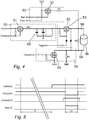
- Timing diagram of Fig. 5 shows how input signals CHARGE, TRIGGER and CONNECT interact to produce output FOG1 during normal conditions.
- the first step for activation of the smoke generator will be to activate input signal CHARGE by setting first active component 51 into ON state. This is done by applying a LOW signal. All other active components being in an OFF state current will flow through first active component 51 and through resistor RD to charging means 60.
- time period T1 in Fig. 5 is equal to about 500ms.
- input signal CHARGE is set to HIGH to set first active component 51 into OFF state. As a result, charging of charging means 60 is stopped.
- Activation of input signal TRIGGER is done by setting it to LOW.
- second active component 53 is set to ON which in practice connects first pole 56 of canister 38 to charging means 60 and will allow a current at a high level to flow into the canister 38.
- the high level current can be about 1A or more.
- smoke is generated during a time period T2.
- T2 is equal to or longer than 5 ms.
Description
- The invention relates to a method and a device for controlling and powering a smoke generator. Generally, a smoke generator is an electrically ignited device for producing a non-toxic opaque smoke. A specific application for smoke generators is the use as an active addition to alarm systems. Such alarm systems are commonly used in domestic houses, industrial premises, commercial premises and office premises as well as other premises and buildings to detect unauthorized intrusion such as burglary, damages and similar. In alarm systems the smoke generator normally is activated in connection with activation of other alarm functions, such as sound signals and a request for assistance that is sent to a remote monitoring station.
- An anti-intrusion security system in accordance with
EP2778599 comprises fog-generating devices which impairs the sight of an intruder when activated. The devices for generating the fog comprise a heat exchanger for heating and vaporising the fluid with a resistor embedded on a body. When an intruder detection system is activated, an appropriate signal is sent to an anti-intrusion security system that initiates delivery of fog. -
EP2719432 discloses a fog-generating device comprising a power source and a reservoir containing fog-generating liquid. An external surveillance system may send an alarm signal to the fog-generating device, upon which a switch is controlled in the fog-generating device which closes a circuit containing the ignition energy source (e.g. a capacitor or supercapacitor) and the ignition means, thereby igniting the reagent. DocumentDE60207349 describes another example of a smoke generation system. - When the appropriate signal is sent to the smoke generator and the smoke generating process has been initiated it is not possible to interrupt or stop the process. Therefore, it is desirable to improve the safety arrangements around the initiating process, so as to reduce the risk for unintentional activation of the smoke generator.
- In accordance with the invention there is provided a device for controlling and powering a smoke generator, said device comprising a power output connected to said smoke generator for activating thereof. The invention relates also to a method for controlling and powering the smoke generator. There is a special concern about the possibility of having an accidental activation of the smoke generator. Once the smoke generation is activated, the pyrotechnic nature of the product disables the possibility of stopping the smoke generation.
- In various embodiments the device is a peripheral comprising a safety circuit and the smoke generator. The smoke generator comprises a smoke generator component, referred to as a canister. The device will generate smoke in the premises after a burglary or danger situation is verified, for instance from a remote monitoring station. For this purpose, the new device can be integrated in presently available alarm systems as any other peripheral, communicating with at least one control unit, also referred to as a gateway, via a radio frequency, RF, interface.
- In various embodiments the device is designed to guarantee a reliable activation during the full life cycle of the device. The device in accordance with the invention will have a very quick and secure action. Emission of smoke starts within seconds of activation and will last at least one minute. The opacity of the smoke is very high.
- In order that the manner in which the above recited and other advantages and objects of the invention are obtained will be readily understood, a more particular description of the invention briefly described above will be rendered by reference to specific embodiments thereof which are illustrated in the appended drawings.
- Understanding that these drawings depict only typical embodiments of the invention and are not therefore to be considered to be limiting of its scope, the invention will be described and explained with additional specificity and detail through the use of the accompanying drawings in which:
- Fig. 1
- is a schematic top view of one embodiment of an installation of an alarm system comprising a device in accordance with the invention,
- Fig. 2
- is a schematic block diagram showing an embodiment of a device comprising a driver circuit in accordance with the invention,
- Fig. 3
- is a schematic block diagram showing an embodiment of a driver circuit in accordance with the invention,
- Fig. 4
- is a schematic circuit diagram showing an embodiment of a driver circuit, and
- Fig. 5
- is a timing diagram showing different steps for enabling and activation of the device in accordance with the invention.
- In
Fig. 1 an alarm system is arranged in premises in the form of abuilding 10. The alarm system comprises at least onecontrol unit 12 also referred to as a gateway that, for example, includes a processor and an alarm unit for providing an alarm signal when the alarm is set off. - The alarm system comprises at least one and preferably a plurality of
premises perimeter detectors 14, such as a firstpremises perimeter detector 14a and a secondpremises perimeter detector 14b. Thepremises perimeter detectors 14 are, for example, detectors sensitive to the presence or passage of persons and objects. For example, presence detectors include motion detectors, such as IR-detectors, and passage detectors include magnetic sensors arranged atwindows 16 and doors, such as anentrance door 18. Other detectors with similar properties can also be included. The alarm system further comprises at least one and preferably a plurality of premisesinterior detectors 20, such as a first premisesinterior detector 20a and a second premisesinterior detector 20b. The interior detectors may include IR-sensors. - The
control unit 12 is connected to thepremises perimeter detectors 14, the premisesinterior detectors 20 and to input means 22, such as a keypad or similar, for arming and disarming thedetectors control unit 12 is activated and controlled by the input means 22. Alternatively, thecontrol unit 12 is provided with the input means 22. Alternatively, the input means 22 is a remote device, such as a wireless remote device. In the illustrated embodiment, the input means 22 is arranged in the vicinity of theentrance door 18. Alternatively, the input means 22 is arranged in any suitable location or is a portable device, such as a cell phone. Thedetectors control unit 12. - In the embodiment of
Fig. 1 thecontrol unit 12 is connected to analarm receiving centre 24, such as a remote alarm receiving centre, either by wire, such as a telephone line as indicated inFig. 1 with a dashed line, or by a wireless telecommunications system such as GSM or other radio frequency systems. The connection also can be through theinternet 26. For example, thecontrol unit 12 is provided with communication means for communicating with the remotealarm receiving centre 24. Alternatively, thealarm receiving centre 24 is located within the premises or within thebuilding 10. In the embodiment shown inFig. 1 the remotealarm receiving centre 24 comprises aweb server 28, a control andcommunications unit 30 and adatabase 32. Theweb server 28 is an interface for a user to set up and to monitor the alarm system of thebuilding 10. Different settings and information regarding the alarm system and different users of the alarm system are stored in thedatabase 32. Communication between the user, the alarm system and the remotealarm receiving centre 24 is processed through the control andcommunications unit 30. - According to one embodiment at least one premises
interior detector 20 comprises or is connected to an image capturing means, such as a camera, video camera or any other type of image capturing means, wherein the image capturing means is activated when saiddetector 20 is triggered. For example, at least one premisesinterior detector 20 comprises an image capturing means, which image capturing means is activated by the triggering of theinterior detector 20 connected to it, so that the image capturing means is switched on when theinterior detector 20 detects an unauthorized intrusion. - In the
building 10 there is provided also asmoke generator 36 capable of producing and distributing an opaque smoke after being initiated and activated by the alarm system, preferably through thecontrol unit 12. Thesmoke generator 36 can be arranged on a wall by a wall attachment or be designed to be placed on a table or shelf. After being activated thesmoke generator 36 will emit smoke that eventually will fill the premises in the building. - The embodiment of the
smoke generator 36 shown inFig. 2 comprises a smoke generator component, referred to as acanister 38. The canister is a chemical pyrotechnic component which is available for instance from French company ALSETECH. The smoke generated is completely non-toxic and contains only very small amounts of CO and CO2. - In various embodiments the
smoke generator 36 is a stand-alone or self-contained unit where a battery or a set of batteries form apower supply unit 40. Communication between thesmoke generator 36 and other peripheral units of the alarm system and specifically thecontrol unit 12 is handled by acommunication unit 42. Thesmoke generator 36 is controlled by acentral unit 44, comprising a processor and memory units. Thecentral unit 44 will communicate with thecontrol unit 12 of the alarm system when an alarm situation occurs and activation of thesmoke generator 36 is desired. Control signals from thecentral unit 44 are forwarded to adriver circuit 46 that is connected to thecanister 38. - An embodiment of the
driver circuit 46 of thesmoke generator 36 as shown inFig. 3 comprises a chargingunit 50, a switchingunit 52 and a connectingunit 54. The chargingunit 50 comprises charging means, such as capacitors or similar components capable of storing electric energy, and electronic circuits for controlling supply of current from thepower supply unit 40 to the charging means, c.f.Fig. 4 . The chargingunit 50 is connected to thecentral unit 44 and will receive a Charge signal when a smoke generator activating signal has been received by thecentral unit 44. The charging process of the charging means will take some time before an appropriate amount of energy has been obtained. In various embodiments a fixed time period is assigned for the charging process. In other embodiments the actual charged amount is measured by the central unit. No activation of the canister is possible during the charging process. A timing process for enabling and activating thesmoke generator 36 is further explained below with reference toFig. 5 . - The
canister 38 is connected to the connectingunit 54 which needs to enter a closing condition to allow thecanister 38 to be activated properly. The closing condition is entered when a Connect signal is received from thedriver circuit 46. The switchingunit 52 is connected to the chargingunit 50 and to thecanister 38. In a final step for activating thecanister 38 theswitching unit 52 receives a trigger signal from thecentral unit 44. The switchingunit 52 then switches on and energy stored in the chargingunit 50 can be passed on to thecanister 38 on the condition that the connectingunit 54 has entered the closing condition. - The
driver circuit 46 further comprises atesting unit 62 which is connected to thecanister 38. Thetesting unit 62 has an input Test and an output Vtest. By applying a signal at input Test it is possible to detect presence of thecanister 38 and also to detect information relating to the physical status of thecanister 38. These data can be used to detect tampering attempts and when exchange of the canister is due. - In the embodiment of a
driver circuit 46 shown inFig. 4 the chargingunit 50 comprises a firstactive component 51. In the selected arrangement of power voltage, grounding of circuits and canister the firstactive component 51 is a P-channel enhancement mode MOSFET, such as one available from DIODES INCORPORATED as DMP2305U. In other arrangements, for instance with opposite polarities of power supply, other suitable components can be used still providing the same function. The chargingunit 50 further comprises charging means 60. A suitable implementation of the charging means 60 is at least one, or as shown inFig. 4 two, capacitors with a total capacity of 6.600 µF. The chargingunit 50 comprises a restricting resistor RD that will limit charging current from power supply VCC to the charging means 60. - The switching
unit 52 comprises in the shown embodiment a secondactive component 53. In the selected arrangement of power voltage, grounding of circuits and canister the secondactive component 53 is a P-channel trench MOSFET, such as one available from NXP SEMICONDUCTORS as PMV27UPE. In other arrangements, for instance with opposite polarities of power supply, other suitable components can be used still providing the same function. An activation signal at input Trigger will connect afirst pole 56 of thecanister 38 to the charging means 60. Restricting resistor RD will limit current also in a situation where an activation signal at input Trigger is given in error during a time period where also a signal is provided at Charge input. - The connecting
unit 54 comprises in the shown embodiment a thirdactive component 55. In the selected arrangement of power voltage, grounding of circuits and canister the thirdactive component 55 is an N-channel trench MOSFET, such as one available from NXP SEMICONDUCTORS as PMV30UN2. In other arrangements, for instance with opposite polarities of power supply, other suitable components can be used still providing the same function. A pre-activation signal at input Connect will connect asecond pole 58 of thecanister 38 to ground (GND). A current limiting resistor RL, which is always connected between the second pole of thecanister 38 and ground (GND) will limit the current through the canister below a level where the canister in is activated. In the shown embodiment RL is 3k Ohm. - The
testing unit 62 comprises a fourthactive component 57. In the selected arrangement of power voltage, grounding of circuits and canister the fourthactive component 57 is a P-channel enhancement mode MOSFET, such as one available from DIODES INCORPORATED as DMP2305U. In other arrangements, for instance with opposite polarities of power supply, other suitable components can be used still providing the same function. By applying a test signal at the Test input fourthactive component 57 will enter an ON state and current will be allowed to flow through a limiting resistor RT to thecanister 38. The limiting resistor RT, normally at about 3k Ohm, will ensure that the current to thecanister 38 will be limited to a value below the value required for activation. In the shown embodiment, the current to the canister will be limited to a maximum value of 1mA, even if the connectingunit 54 accidently is activated when the testing unit is activated. The current that actually flows through the canister when the test signal is applied will indicate presence of thecanister 38 and also to some extent the status of content of the canister. A test output signal, Vtest, can be obtained at the fourthactive component 57. - In a default mode all active components are in the OFF state. In this mode
first pole 56 ofcanister 38 is connected to ground through shorting resistor RS and current limiting resistor RL.Second pole 58 ofcanister 38 is connected to ground through current limiting resistor RL. In the embodiment shown inFig. 4 RS is 10k Ohm. As a result, the smoke generator cannot be activated in this mode. - Normal steps for activating the smoke generator to provide smoke include provision of input signal at input Charge. This input signal and also other signals indicated in
Fig. 3 andFig. 4 are provided bycentral unit 44 on the basis of signals received from thecontrol unit 12 indicating an alarm situation. Below the term HIGH implies supply voltage VCC or a voltage level close to that. Correspondingly, the term LOW implies ground GND or a voltage level close to that. An ON state of all active components corresponds to a closed switch condition, that is a condition where a maximum current flows through the component. An OFF state of all active components corresponds to an open switch condition, that is a condition where practically no current flows through the component. Signals at HIGH level are considered to be of opposite polarities as compared to signals at LOW level. - The type of semiconductor used as first
active component 51 is put into an ON state by changing from HIGH to a LOW signal at the gate of the P-channel enhancement mode MOSFET. As a result, current will flow from power supply at VCC and start charging the charging means 60. The time required for charging the charging means 60 to an appropriate level may vary in dependence on selected components and voltage levels. In the embodiment shown inFig. 4 a normal charging time is about 500 ms. Even when charged to an appropriate level no energy is automatically transferred to thecanister 38 because the secondactive component 53 is maintained at an OFF state in which current is prevented from passing through. Also thirdactive component 55 is kept at an OFF state to further prevent activation ofcanister 38. -
First pole 56 ofcanister 38 is connected to "positive" units that will provide positive signals for activation ofcanister 38. These units are chargingunit 50 and switchingunit 52. Also thetesting unit 62 is connected tofirst pole 56 ofcanister 38.Second pole 58 ofcanister 38 is connected to a "negative" unit that will provide a negative (or grounding) signal. Smoke generation requires that "positive" as well as "negative" units are activated during an overlapping time period. If "positive" chargingunit 50 or "positive" switchingunit 52 is activated while "negative" connectingunit 54 is not activated the maximum current that can flow through thecanister 38 is limited by resistor RL. The limited current cannot activate smoke generation. - In a similar manner, if "negative" connecting
unit 54 is activated while "positive" chargingunit 50 and "positive" switchingunit 52 are not activated no current can be supplied from power supply because firstactive component 51 and secondactive component 53 are both in the OFF state. As a result, no smoke generation can be activated. Furthermore, "positive" units and "negative" units in the shown embodiment are controlled with opposite polarities to reduce the probability of an accidental application of control signals insmoke generator 36. - Accidental activation of both control signals CHARGE and TRIGGER at the same time will not activate the smoke generation, as resistor RD will limit current to about 40mA, which is a safe value. The designed charging time of about 500ms will allow to incorporate easily safety mechanisms in the firmware to prevent undesired activation.
- Timing diagram of
Fig. 5 shows how input signals CHARGE, TRIGGER and CONNECT interact to produce output FOG1 during normal conditions. The first step for activation of the smoke generator will be to activate input signal CHARGE by setting firstactive component 51 into ON state. This is done by applying a LOW signal. All other active components being in an OFF state current will flow through firstactive component 51 and through resistor RD to chargingmeans 60. As set out above the time required for the charging means 60 to an appropriate level would be about 500ms. Thus, time period T1 inFig. 5 is equal to about 500ms. After this time period input signal CHARGE is set to HIGH to set firstactive component 51 into OFF state. As a result, charging of charging means 60 is stopped. - In the shown embodiment, there is a short delay and then input signal CONNECT is activated by setting it to HIGH. In this state, third
active component 55 will be set to ON resulting in a very low resistance. In practice this means thatsecond pole 58 ofcanister 38 is connected to ground GND. This is a preparation for full activation of the canister which is done by activating input signal TRIGGER. Input signal CONNECT is maintained at HIGH during at least the full length of activated input signal TRIGGER. - Activation of input signal TRIGGER is done by setting it to LOW. As a result, second
active component 53 is set to ON which in practice connectsfirst pole 56 ofcanister 38 to charging means 60 and will allow a current at a high level to flow into thecanister 38. Depending on the type ofcanister 38 the high level current can be about 1A or more. As a result, smoke is generated during a time period T2. In the embodiment described above T2 is equal to or longer than 5 ms. - While certain illustrative embodiments of the invention have been described in particularity, it will be understood that various other modifications will be readily apparent to those skilled in the art without departing from the scope and spirit of the invention. Accordingly, it is not intended that the scope of the claims appended hereto be limited to the description set forth herein but rather that the claims be construed as encompassing all equivalents of the present invention which are apparent to those skilled in the art to which the invention pertains.
Claims (8)
- A driver circuit (46) for controlling and powering a smoke generating canister (38), said driver circuit (46) comprising a power output connected to said smoke generating canister (38) for activation thereof, wherein said driver circuit (46) comprisesa charging unit (50) providing after a charging process sufficient power for igniting and driving said smoke generating canister (38),a switching unit (52) connected to said charging unit (50) and to a first pole (56) of said smoke generating canister (38) for releasing power from said charging unit (50) to said smoke generating canister (38), anda connecting unit (54) connected to a second pole (58) of said smoke generating canister (38) for allowing power to flow through said smoke generating canister (38), wherein activation of both said connecting unit (54) and said switching unit (52) during an overlapping time period is required for activation of said smoke generating canister (38).
- A driver circuit (46) as claimed in claim 1, wherein said connecting unit (54) and said switching unit (52) are activated by signals of opposite polarities.
- A driver circuit (46) as claimed in claim 1, wherein said charging unit (50) comprises first active component (51), said switching unit (52) comprises second active component (53), and said connecting unit (54) comprises third active component (55), said first active component (51), said second active component (53), and said third active component (55) having an ON state corresponding to a closed switch condition and an OFF state corresponding to an open switch condition.
- A driver circuit (46) as claimed in claim 3, wherein said connecting unit (54) comprises a current limiting resistor, RL, connected between said second pole (58) of said canister (38) and ground (GND) to limit current through said canister (38) when third active component (55) is in OFF state.
- A driver circuit (46) as claimed in claim 3 or claim 4, wherein said charging unit (50) comprises a restricting resistor RD connected between said first active component (51) and charging means (60) for limiting current flowing from said first active component (51).
- A driver circuit (46) as claimed in claim 1, wherein a testing unit (62) is connected to said canister (38) for providing limited current to run through said canister (38) and wherein an actual current flow from said testing unit (62) is determined to be indicative of the canister (38) being connected or disconnected.
- A method for driving for controlling and powering a smoke generating canister (38) having a first pole (56) and a second pole (58) for receiving and draining, respectively, current, and applying a charging signal at a charging input of a driver circuit (46) for charging a charging means (60) to store energy therein, applying a control signal to a connect input of said driver circuit (46) for switching a connecting unit (54) to an ON state in which current is allowed to flow from said smoke generating canister (38) to ground (GND), and applying a trigger signal at a trigger input of switching unit (52) to an ON state wherein only when both the connecting unit(54) and the switching unit (52) are in an ON state for an overlapping time period the current from said charging means is transferred to said smoke generating canister (38) and from said smoke generating canister (38) to ground (GND) and thereby activating the smoke generating canister (38).
- A smoke generator (36) comprising a communication unit (42), a central unit (44), a driver circuit (46), a power unit (40), and a smoke generating canister (38), wherein said communication unit (42) is arranged to receive a signal for activation of said smoke generating canister (38), said central unit (44) is arranged for producing a plurality of control signals for activating and controlling said driver circuit (46), and said power unit (40) is arranged to supply power various units of the smoke generator (36), so as to make said smoke generator (36) a self-contained unit, wherein said driver circuit (46) comprisesa charging unit (50) providing after a charging process sufficient power for igniting and driving said smoke generating canister (38),a switching unit (52) connected to said charging unit (50) and to a first pole (56) of said smoke generating canister (38) for releasing power from said charging unit (50) to said smoke generating canister (38), anda connecting unit (54) connected to a second pole (58) of said smoke generating canister (38) for allowing power to flow through said smoke generating canister (38), wherein activation of both said connecting unit (54) and said switching unit (52) during an overlapping time period is required for activation of said smoke generating canister (38).
Applications Claiming Priority (2)
| Application Number | Priority Date | Filing Date | Title |
|---|---|---|---|
| EP16197292.2A EP3319055A1 (en) | 2016-11-04 | 2016-11-04 | A method and a device for controlling and powering a smoke generator |
| PCT/EP2017/077901 WO2018083091A1 (en) | 2016-11-04 | 2017-10-31 | A method and a device for controlling and powering a smoke generator |
Publications (2)
| Publication Number | Publication Date |
|---|---|
| EP3535740A1 EP3535740A1 (en) | 2019-09-11 |
| EP3535740B1 true EP3535740B1 (en) | 2020-08-05 |
Family
ID=57348463
Family Applications (2)
| Application Number | Title | Priority Date | Filing Date |
|---|---|---|---|
| EP16197292.2A Pending EP3319055A1 (en) | 2016-11-04 | 2016-11-04 | A method and a device for controlling and powering a smoke generator |
| EP17791107.0A Active EP3535740B1 (en) | 2016-11-04 | 2017-10-31 | A method and a device for controlling and powering a smoke generator |
Family Applications Before (1)
| Application Number | Title | Priority Date | Filing Date |
|---|---|---|---|
| EP16197292.2A Pending EP3319055A1 (en) | 2016-11-04 | 2016-11-04 | A method and a device for controlling and powering a smoke generator |
Country Status (13)
| Country | Link |
|---|---|
| US (1) | US11098984B2 (en) |
| EP (2) | EP3319055A1 (en) |
| AU (1) | AU2017353293B2 (en) |
| BR (1) | BR112019009056B1 (en) |
| CA (1) | CA3042574A1 (en) |
| CL (1) | CL2019001223A1 (en) |
| CO (1) | CO2019004564A2 (en) |
| ES (1) | ES2829334T3 (en) |
| IL (1) | IL266396B (en) |
| MX (1) | MX2019005210A (en) |
| PE (1) | PE20191285A1 (en) |
| WO (1) | WO2018083091A1 (en) |
| ZA (1) | ZA201902853B (en) |
Families Citing this family (2)
| Publication number | Priority date | Publication date | Assignee | Title |
|---|---|---|---|---|
| EP3543981A3 (en) * | 2016-11-04 | 2020-01-22 | Verisure Sàrl | Smoke generator with deflector |
| EP4207122A1 (en) * | 2021-12-29 | 2023-07-05 | Verisure Sàrl | Intruder localisation |
Family Cites Families (8)
| Publication number | Priority date | Publication date | Assignee | Title |
|---|---|---|---|---|
| DE69306406T2 (en) * | 1992-09-12 | 1997-07-10 | Paul Anton Dards | Burglar quenching system |
| EP0623906B1 (en) * | 1992-11-26 | 1999-11-03 | Secom Co., Ltd. | Burglar-proofing system and theft proofing apparatus |
| EP0664532A1 (en) * | 1994-01-21 | 1995-07-26 | Taher Burayez | Motor vehicle security device |
| GB9708447D0 (en) * | 1997-04-26 | 1997-06-18 | Gillrange Limited | Independent intruder detection and deterrent system |
| FR2829861B1 (en) * | 2001-09-20 | 2003-11-21 | F V S | INTERACTIVE METHOD FOR STARTING AN ANTI-INTRUSION APPARATUS, IN PARTICULAR A SMOKE, ASSOCIATED DEVICE AND SYSTEM USING THE SAME |
| AU2007234883A1 (en) * | 2006-04-03 | 2007-10-18 | Bluwav Systems, Llc | Vehicle power unit designed as retrofittable axle comprising motor, battery and suspension |
| BE1021433B1 (en) | 2012-10-11 | 2015-11-19 | Bandit N.V. | MISTLING DEVICE AND ACCOMPANY REMOVABLE HOUSING |
| ITBS20130035A1 (en) | 2013-03-13 | 2014-09-14 | Mod Security S R L | ANTI-INTRUSION SAFETY SYSTEM TO GENERATE A MIST |
-
2016
- 2016-11-04 EP EP16197292.2A patent/EP3319055A1/en active Pending
-
2017
- 2017-10-31 US US16/347,221 patent/US11098984B2/en active Active
- 2017-10-31 AU AU2017353293A patent/AU2017353293B2/en active Active
- 2017-10-31 MX MX2019005210A patent/MX2019005210A/en unknown
- 2017-10-31 ES ES17791107T patent/ES2829334T3/en active Active
- 2017-10-31 PE PE2019000933A patent/PE20191285A1/en unknown
- 2017-10-31 CA CA3042574A patent/CA3042574A1/en active Pending
- 2017-10-31 WO PCT/EP2017/077901 patent/WO2018083091A1/en unknown
- 2017-10-31 BR BR112019009056-8A patent/BR112019009056B1/en active IP Right Grant
- 2017-10-31 EP EP17791107.0A patent/EP3535740B1/en active Active
-
2019
- 2019-05-01 IL IL266396A patent/IL266396B/en unknown
- 2019-05-03 CL CL2019001223A patent/CL2019001223A1/en unknown
- 2019-05-03 CO CONC2019/0004564A patent/CO2019004564A2/en unknown
- 2019-05-07 ZA ZA2019/02853A patent/ZA201902853B/en unknown
Non-Patent Citations (1)
| Title |
|---|
| None * |
Also Published As
| Publication number | Publication date |
|---|---|
| BR112019009056B1 (en) | 2023-11-14 |
| ES2829334T3 (en) | 2021-05-31 |
| EP3535740A1 (en) | 2019-09-11 |
| IL266396B (en) | 2022-06-01 |
| PE20191285A1 (en) | 2019-09-20 |
| US11098984B2 (en) | 2021-08-24 |
| MX2019005210A (en) | 2019-10-07 |
| BR112019009056A2 (en) | 2019-07-16 |
| WO2018083091A1 (en) | 2018-05-11 |
| CA3042574A1 (en) | 2018-05-11 |
| CO2019004564A2 (en) | 2019-09-18 |
| US20200333115A1 (en) | 2020-10-22 |
| AU2017353293B2 (en) | 2021-11-25 |
| IL266396A (en) | 2019-06-30 |
| ZA201902853B (en) | 2020-01-29 |
| AU2017353293A1 (en) | 2019-05-23 |
| CL2019001223A1 (en) | 2019-09-06 |
| EP3319055A1 (en) | 2018-05-09 |
Similar Documents
| Publication | Publication Date | Title |
|---|---|---|
| US5465094A (en) | Two terminal micropower radar sensor | |
| US4103294A (en) | Intruder deterrent apparatus and method | |
| EP3535740B1 (en) | A method and a device for controlling and powering a smoke generator | |
| US3425050A (en) | Theft-preventing alarm device | |
| US11423765B2 (en) | Portable alarm system | |
| CN106785155B (en) | A kind of cell safety detection device, battery modules and electric vehicle | |
| Eseosa et al. | GSM based intelligent home security system for intrusion detection | |
| GB2384604A (en) | Remote property monitoring system using mobile phone text messaging | |
| EP3625780A1 (en) | System and method for automatically disarming an intrusion detection system | |
| KR101777396B1 (en) | An Device and A System Of An Intelligent Indoor Warning For Open And Shuts Of A oor | |
| CN207182599U (en) | A kind of gas leakage remotely monitors and fire-warning device | |
| Raghavendran | SMS based wireless home appliance control system | |
| US4276545A (en) | Door activated burglar alarm utilizing time delay | |
| CN207429616U (en) | Climbers with display function | |
| CN217543954U (en) | Intelligent alarm device | |
| CN110886571A (en) | Intelligent safety door | |
| US20150042472A1 (en) | Non-battery powered wireless security system | |
| CN109343435A (en) | A kind of home security system | |
| CN112070998B (en) | Household anti-theft system controlled by embedded technology | |
| CN209976366U (en) | Intelligent safety door | |
| US20230053570A1 (en) | Portable alarm system | |
| CN203924980U (en) | Double-opening type security device | |
| CN104077865A (en) | Novel domestic security alarm system | |
| CN106910305A (en) | Intelligent wireless network door sensor burglar alarm | |
| ES2797775T3 (en) | An anti-theft and anti-tamper protection system |
Legal Events
| Date | Code | Title | Description |
|---|---|---|---|
| STAA | Information on the status of an ep patent application or granted ep patent |
Free format text: STATUS: UNKNOWN |
|
| STAA | Information on the status of an ep patent application or granted ep patent |
Free format text: STATUS: THE INTERNATIONAL PUBLICATION HAS BEEN MADE |
|
| PUAI | Public reference made under article 153(3) epc to a published international application that has entered the european phase |
Free format text: ORIGINAL CODE: 0009012 |
|
| STAA | Information on the status of an ep patent application or granted ep patent |
Free format text: STATUS: REQUEST FOR EXAMINATION WAS MADE |
|
| 17P | Request for examination filed |
Effective date: 20190529 |
|
| AK | Designated contracting states |
Kind code of ref document: A1 Designated state(s): AL AT BE BG CH CY CZ DE DK EE ES FI FR GB GR HR HU IE IS IT LI LT LU LV MC MK MT NL NO PL PT RO RS SE SI SK SM TR |
|
| AX | Request for extension of the european patent |
Extension state: BA ME |
|
| DAV | Request for validation of the european patent (deleted) | ||
| DAX | Request for extension of the european patent (deleted) | ||
| GRAP | Despatch of communication of intention to grant a patent |
Free format text: ORIGINAL CODE: EPIDOSNIGR1 |
|
| STAA | Information on the status of an ep patent application or granted ep patent |
Free format text: STATUS: GRANT OF PATENT IS INTENDED |
|
| INTG | Intention to grant announced |
Effective date: 20200409 |
|
| GRAS | Grant fee paid |
Free format text: ORIGINAL CODE: EPIDOSNIGR3 |
|
| GRAA | (expected) grant |
Free format text: ORIGINAL CODE: 0009210 |
|
| STAA | Information on the status of an ep patent application or granted ep patent |
Free format text: STATUS: THE PATENT HAS BEEN GRANTED |
|
| AK | Designated contracting states |
Kind code of ref document: B1 Designated state(s): AL AT BE BG CH CY CZ DE DK EE ES FI FR GB GR HR HU IE IS IT LI LT LU LV MC MK MT NL NO PL PT RO RS SE SI SK SM TR |
|
| REG | Reference to a national code |
Ref country code: GB Ref legal event code: FG4D |
|
| REG | Reference to a national code |
Ref country code: CH Ref legal event code: EP |
|
| REG | Reference to a national code |
Ref country code: AT Ref legal event code: REF Ref document number: 1299790 Country of ref document: AT Kind code of ref document: T Effective date: 20200815 |
|
| REG | Reference to a national code |
Ref country code: DE Ref legal event code: R096 Ref document number: 602017021254 Country of ref document: DE |
|
| REG | Reference to a national code |
Ref country code: IE Ref legal event code: FG4D |
|
| REG | Reference to a national code |
Ref country code: CH Ref legal event code: NV Representative=s name: NOVAGRAAF INTERNATIONAL SA, CH |
|
| REG | Reference to a national code |
Ref country code: SE Ref legal event code: TRGR |
|
| REG | Reference to a national code |
Ref country code: LT Ref legal event code: MG4D |
|
| REG | Reference to a national code |
Ref country code: NO Ref legal event code: T2 Effective date: 20200805 |
|
| REG | Reference to a national code |
Ref country code: NL Ref legal event code: MP Effective date: 20200805 |
|
| REG | Reference to a national code |
Ref country code: AT Ref legal event code: MK05 Ref document number: 1299790 Country of ref document: AT Kind code of ref document: T Effective date: 20200805 |
|
| PG25 | Lapsed in a contracting state [announced via postgrant information from national office to epo] |
Ref country code: BG Free format text: LAPSE BECAUSE OF FAILURE TO SUBMIT A TRANSLATION OF THE DESCRIPTION OR TO PAY THE FEE WITHIN THE PRESCRIBED TIME-LIMIT Effective date: 20201105 Ref country code: GR Free format text: LAPSE BECAUSE OF FAILURE TO SUBMIT A TRANSLATION OF THE DESCRIPTION OR TO PAY THE FEE WITHIN THE PRESCRIBED TIME-LIMIT Effective date: 20201106 Ref country code: AT Free format text: LAPSE BECAUSE OF FAILURE TO SUBMIT A TRANSLATION OF THE DESCRIPTION OR TO PAY THE FEE WITHIN THE PRESCRIBED TIME-LIMIT Effective date: 20200805 Ref country code: FI Free format text: LAPSE BECAUSE OF FAILURE TO SUBMIT A TRANSLATION OF THE DESCRIPTION OR TO PAY THE FEE WITHIN THE PRESCRIBED TIME-LIMIT Effective date: 20200805 Ref country code: LT Free format text: LAPSE BECAUSE OF FAILURE TO SUBMIT A TRANSLATION OF THE DESCRIPTION OR TO PAY THE FEE WITHIN THE PRESCRIBED TIME-LIMIT Effective date: 20200805 Ref country code: PT Free format text: LAPSE BECAUSE OF FAILURE TO SUBMIT A TRANSLATION OF THE DESCRIPTION OR TO PAY THE FEE WITHIN THE PRESCRIBED TIME-LIMIT Effective date: 20201207 Ref country code: HR Free format text: LAPSE BECAUSE OF FAILURE TO SUBMIT A TRANSLATION OF THE DESCRIPTION OR TO PAY THE FEE WITHIN THE PRESCRIBED TIME-LIMIT Effective date: 20200805 |
|
| PG25 | Lapsed in a contracting state [announced via postgrant information from national office to epo] |
Ref country code: PL Free format text: LAPSE BECAUSE OF FAILURE TO SUBMIT A TRANSLATION OF THE DESCRIPTION OR TO PAY THE FEE WITHIN THE PRESCRIBED TIME-LIMIT Effective date: 20200805 Ref country code: LV Free format text: LAPSE BECAUSE OF FAILURE TO SUBMIT A TRANSLATION OF THE DESCRIPTION OR TO PAY THE FEE WITHIN THE PRESCRIBED TIME-LIMIT Effective date: 20200805 Ref country code: RS Free format text: LAPSE BECAUSE OF FAILURE TO SUBMIT A TRANSLATION OF THE DESCRIPTION OR TO PAY THE FEE WITHIN THE PRESCRIBED TIME-LIMIT Effective date: 20200805 Ref country code: NL Free format text: LAPSE BECAUSE OF FAILURE TO SUBMIT A TRANSLATION OF THE DESCRIPTION OR TO PAY THE FEE WITHIN THE PRESCRIBED TIME-LIMIT Effective date: 20200805 Ref country code: IS Free format text: LAPSE BECAUSE OF FAILURE TO SUBMIT A TRANSLATION OF THE DESCRIPTION OR TO PAY THE FEE WITHIN THE PRESCRIBED TIME-LIMIT Effective date: 20201205 |
|
| PG25 | Lapsed in a contracting state [announced via postgrant information from national office to epo] |
Ref country code: SM Free format text: LAPSE BECAUSE OF FAILURE TO SUBMIT A TRANSLATION OF THE DESCRIPTION OR TO PAY THE FEE WITHIN THE PRESCRIBED TIME-LIMIT Effective date: 20200805 Ref country code: EE Free format text: LAPSE BECAUSE OF FAILURE TO SUBMIT A TRANSLATION OF THE DESCRIPTION OR TO PAY THE FEE WITHIN THE PRESCRIBED TIME-LIMIT Effective date: 20200805 Ref country code: RO Free format text: LAPSE BECAUSE OF FAILURE TO SUBMIT A TRANSLATION OF THE DESCRIPTION OR TO PAY THE FEE WITHIN THE PRESCRIBED TIME-LIMIT Effective date: 20200805 Ref country code: DK Free format text: LAPSE BECAUSE OF FAILURE TO SUBMIT A TRANSLATION OF THE DESCRIPTION OR TO PAY THE FEE WITHIN THE PRESCRIBED TIME-LIMIT Effective date: 20200805 Ref country code: CZ Free format text: LAPSE BECAUSE OF FAILURE TO SUBMIT A TRANSLATION OF THE DESCRIPTION OR TO PAY THE FEE WITHIN THE PRESCRIBED TIME-LIMIT Effective date: 20200805 |
|
| REG | Reference to a national code |
Ref country code: DE Ref legal event code: R097 Ref document number: 602017021254 Country of ref document: DE |
|
| PG25 | Lapsed in a contracting state [announced via postgrant information from national office to epo] |
Ref country code: AL Free format text: LAPSE BECAUSE OF FAILURE TO SUBMIT A TRANSLATION OF THE DESCRIPTION OR TO PAY THE FEE WITHIN THE PRESCRIBED TIME-LIMIT Effective date: 20200805 |
|
| REG | Reference to a national code |
Ref country code: ES Ref legal event code: FG2A Ref document number: 2829334 Country of ref document: ES Kind code of ref document: T3 Effective date: 20210531 |
|
| PLBE | No opposition filed within time limit |
Free format text: ORIGINAL CODE: 0009261 |
|
| STAA | Information on the status of an ep patent application or granted ep patent |
Free format text: STATUS: NO OPPOSITION FILED WITHIN TIME LIMIT |
|
| PG25 | Lapsed in a contracting state [announced via postgrant information from national office to epo] |
Ref country code: LU Free format text: LAPSE BECAUSE OF NON-PAYMENT OF DUE FEES Effective date: 20201031 Ref country code: SK Free format text: LAPSE BECAUSE OF FAILURE TO SUBMIT A TRANSLATION OF THE DESCRIPTION OR TO PAY THE FEE WITHIN THE PRESCRIBED TIME-LIMIT Effective date: 20200805 Ref country code: MC Free format text: LAPSE BECAUSE OF FAILURE TO SUBMIT A TRANSLATION OF THE DESCRIPTION OR TO PAY THE FEE WITHIN THE PRESCRIBED TIME-LIMIT Effective date: 20200805 |
|
| 26N | No opposition filed |
Effective date: 20210507 |
|
| PG25 | Lapsed in a contracting state [announced via postgrant information from national office to epo] |
Ref country code: SI Free format text: LAPSE BECAUSE OF FAILURE TO SUBMIT A TRANSLATION OF THE DESCRIPTION OR TO PAY THE FEE WITHIN THE PRESCRIBED TIME-LIMIT Effective date: 20200805 |
|
| PG25 | Lapsed in a contracting state [announced via postgrant information from national office to epo] |
Ref country code: IE Free format text: LAPSE BECAUSE OF NON-PAYMENT OF DUE FEES Effective date: 20201031 |
|
| PG25 | Lapsed in a contracting state [announced via postgrant information from national office to epo] |
Ref country code: TR Free format text: LAPSE BECAUSE OF FAILURE TO SUBMIT A TRANSLATION OF THE DESCRIPTION OR TO PAY THE FEE WITHIN THE PRESCRIBED TIME-LIMIT Effective date: 20200805 Ref country code: MT Free format text: LAPSE BECAUSE OF FAILURE TO SUBMIT A TRANSLATION OF THE DESCRIPTION OR TO PAY THE FEE WITHIN THE PRESCRIBED TIME-LIMIT Effective date: 20200805 Ref country code: CY Free format text: LAPSE BECAUSE OF FAILURE TO SUBMIT A TRANSLATION OF THE DESCRIPTION OR TO PAY THE FEE WITHIN THE PRESCRIBED TIME-LIMIT Effective date: 20200805 |
|
| PG25 | Lapsed in a contracting state [announced via postgrant information from national office to epo] |
Ref country code: MK Free format text: LAPSE BECAUSE OF FAILURE TO SUBMIT A TRANSLATION OF THE DESCRIPTION OR TO PAY THE FEE WITHIN THE PRESCRIBED TIME-LIMIT Effective date: 20200805 |
|
| PGFP | Annual fee paid to national office [announced via postgrant information from national office to epo] |
Ref country code: BE Payment date: 20221020 Year of fee payment: 6 |
|
| PGFP | Annual fee paid to national office [announced via postgrant information from national office to epo] |
Ref country code: GB Payment date: 20231027 Year of fee payment: 7 |
|
| PGFP | Annual fee paid to national office [announced via postgrant information from national office to epo] |
Ref country code: ES Payment date: 20231102 Year of fee payment: 7 |
|
| PGFP | Annual fee paid to national office [announced via postgrant information from national office to epo] |
Ref country code: SE Payment date: 20231027 Year of fee payment: 7 Ref country code: NO Payment date: 20231027 Year of fee payment: 7 Ref country code: IT Payment date: 20231023 Year of fee payment: 7 Ref country code: FR Payment date: 20231025 Year of fee payment: 7 Ref country code: DE Payment date: 20231027 Year of fee payment: 7 Ref country code: CH Payment date: 20231102 Year of fee payment: 7 |
|
| PGFP | Annual fee paid to national office [announced via postgrant information from national office to epo] |
Ref country code: BE Payment date: 20231027 Year of fee payment: 7 |