EP3535637B1 - Operating device for a vehicle component - Google Patents
Operating device for a vehicle component Download PDFInfo
- Publication number
- EP3535637B1 EP3535637B1 EP17797892.1A EP17797892A EP3535637B1 EP 3535637 B1 EP3535637 B1 EP 3535637B1 EP 17797892 A EP17797892 A EP 17797892A EP 3535637 B1 EP3535637 B1 EP 3535637B1
- Authority
- EP
- European Patent Office
- Prior art keywords
- operating
- unit
- element unit
- operating element
- display
- Prior art date
- Legal status (The legal status is an assumption and is not a legal conclusion. Google has not performed a legal analysis and makes no representation as to the accuracy of the status listed.)
- Active
Links
- 238000004891 communication Methods 0.000 claims description 21
- 238000011156 evaluation Methods 0.000 claims description 16
- 230000003287 optical effect Effects 0.000 claims description 8
- 230000002457 bidirectional effect Effects 0.000 claims description 3
- 230000008054 signal transmission Effects 0.000 claims description 3
- 238000012545 processing Methods 0.000 claims description 2
- 238000013479 data entry Methods 0.000 claims 1
- 230000002441 reversible effect Effects 0.000 claims 1
- 238000001514 detection method Methods 0.000 description 32
- 230000005540 biological transmission Effects 0.000 description 15
- 230000001939 inductive effect Effects 0.000 description 5
- 238000013459 approach Methods 0.000 description 4
- 101100390736 Danio rerio fign gene Proteins 0.000 description 3
- 101100390738 Mus musculus Fign gene Proteins 0.000 description 3
- 230000000994 depressogenic effect Effects 0.000 description 3
- 238000003825 pressing Methods 0.000 description 3
- 238000004026 adhesive bonding Methods 0.000 description 2
- 238000012790 confirmation Methods 0.000 description 2
- 230000000881 depressing effect Effects 0.000 description 2
- 230000007246 mechanism Effects 0.000 description 2
- IOPBNBSKOPJKEG-UHFFFAOYSA-N 1,2-dichloro-3-(3,5-dichlorophenyl)benzene Chemical compound ClC1=CC(Cl)=CC(C=2C(=C(Cl)C=CC=2)Cl)=C1 IOPBNBSKOPJKEG-UHFFFAOYSA-N 0.000 description 1
- XLDBTRJKXLKYTC-UHFFFAOYSA-N 2,3,4,4'-tetrachlorobiphenyl Chemical compound C1=CC(Cl)=CC=C1C1=CC=C(Cl)C(Cl)=C1Cl XLDBTRJKXLKYTC-UHFFFAOYSA-N 0.000 description 1
- 238000005033 Fourier transform infrared spectroscopy Methods 0.000 description 1
- 230000003213 activating effect Effects 0.000 description 1
- 239000000853 adhesive Substances 0.000 description 1
- 230000001070 adhesive effect Effects 0.000 description 1
- 238000004378 air conditioning Methods 0.000 description 1
- 230000008859 change Effects 0.000 description 1
- 238000010276 construction Methods 0.000 description 1
- 230000001419 dependent effect Effects 0.000 description 1
- 238000013461 design Methods 0.000 description 1
- 238000011161 development Methods 0.000 description 1
- 238000006073 displacement reaction Methods 0.000 description 1
- 238000009826 distribution Methods 0.000 description 1
- 238000005516 engineering process Methods 0.000 description 1
- 239000003292 glue Substances 0.000 description 1
- 238000003306 harvesting Methods 0.000 description 1
- 238000012905 input function Methods 0.000 description 1
- 230000010354 integration Effects 0.000 description 1
- 238000004519 manufacturing process Methods 0.000 description 1
- 238000001465 metallisation Methods 0.000 description 1
- 239000013307 optical fiber Substances 0.000 description 1
- 230000009467 reduction Effects 0.000 description 1
- 230000000284 resting effect Effects 0.000 description 1
- 238000012546 transfer Methods 0.000 description 1
- 230000007704 transition Effects 0.000 description 1
Images
Classifications
-
- B—PERFORMING OPERATIONS; TRANSPORTING
- B60—VEHICLES IN GENERAL
- B60K—ARRANGEMENT OR MOUNTING OF PROPULSION UNITS OR OF TRANSMISSIONS IN VEHICLES; ARRANGEMENT OR MOUNTING OF PLURAL DIVERSE PRIME-MOVERS IN VEHICLES; AUXILIARY DRIVES FOR VEHICLES; INSTRUMENTATION OR DASHBOARDS FOR VEHICLES; ARRANGEMENTS IN CONNECTION WITH COOLING, AIR INTAKE, GAS EXHAUST OR FUEL SUPPLY OF PROPULSION UNITS IN VEHICLES
- B60K35/00—Arrangement of adaptations of instruments
-
- B60K35/10—
-
- B60K35/212—
-
- B—PERFORMING OPERATIONS; TRANSPORTING
- B60—VEHICLES IN GENERAL
- B60R—VEHICLES, VEHICLE FITTINGS, OR VEHICLE PARTS, NOT OTHERWISE PROVIDED FOR
- B60R16/00—Electric or fluid circuits specially adapted for vehicles and not otherwise provided for; Arrangement of elements of electric or fluid circuits specially adapted for vehicles and not otherwise provided for
- B60R16/02—Electric or fluid circuits specially adapted for vehicles and not otherwise provided for; Arrangement of elements of electric or fluid circuits specially adapted for vehicles and not otherwise provided for electric constitutive elements
- B60R16/03—Electric or fluid circuits specially adapted for vehicles and not otherwise provided for; Arrangement of elements of electric or fluid circuits specially adapted for vehicles and not otherwise provided for electric constitutive elements for supply of electrical power to vehicle subsystems or for
-
- G—PHYSICS
- G06—COMPUTING; CALCULATING OR COUNTING
- G06F—ELECTRIC DIGITAL DATA PROCESSING
- G06F3/00—Input arrangements for transferring data to be processed into a form capable of being handled by the computer; Output arrangements for transferring data from processing unit to output unit, e.g. interface arrangements
- G06F3/01—Input arrangements or combined input and output arrangements for interaction between user and computer
- G06F3/016—Input arrangements with force or tactile feedback as computer generated output to the user
-
- G—PHYSICS
- G06—COMPUTING; CALCULATING OR COUNTING
- G06F—ELECTRIC DIGITAL DATA PROCESSING
- G06F3/00—Input arrangements for transferring data to be processed into a form capable of being handled by the computer; Output arrangements for transferring data from processing unit to output unit, e.g. interface arrangements
- G06F3/01—Input arrangements or combined input and output arrangements for interaction between user and computer
- G06F3/02—Input arrangements using manually operated switches, e.g. using keyboards or dials
- G06F3/0202—Constructional details or processes of manufacture of the input device
-
- G—PHYSICS
- G06—COMPUTING; CALCULATING OR COUNTING
- G06F—ELECTRIC DIGITAL DATA PROCESSING
- G06F3/00—Input arrangements for transferring data to be processed into a form capable of being handled by the computer; Output arrangements for transferring data from processing unit to output unit, e.g. interface arrangements
- G06F3/01—Input arrangements or combined input and output arrangements for interaction between user and computer
- G06F3/03—Arrangements for converting the position or the displacement of a member into a coded form
- G06F3/033—Pointing devices displaced or positioned by the user, e.g. mice, trackballs, pens or joysticks; Accessories therefor
- G06F3/0354—Pointing devices displaced or positioned by the user, e.g. mice, trackballs, pens or joysticks; Accessories therefor with detection of 2D relative movements between the device, or an operating part thereof, and a plane or surface, e.g. 2D mice, trackballs, pens or pucks
- G06F3/03547—Touch pads, in which fingers can move on a surface
-
- G—PHYSICS
- G06—COMPUTING; CALCULATING OR COUNTING
- G06F—ELECTRIC DIGITAL DATA PROCESSING
- G06F3/00—Input arrangements for transferring data to be processed into a form capable of being handled by the computer; Output arrangements for transferring data from processing unit to output unit, e.g. interface arrangements
- G06F3/01—Input arrangements or combined input and output arrangements for interaction between user and computer
- G06F3/03—Arrangements for converting the position or the displacement of a member into a coded form
- G06F3/033—Pointing devices displaced or positioned by the user, e.g. mice, trackballs, pens or joysticks; Accessories therefor
- G06F3/038—Control and interface arrangements therefor, e.g. drivers or device-embedded control circuitry
-
- G—PHYSICS
- G06—COMPUTING; CALCULATING OR COUNTING
- G06F—ELECTRIC DIGITAL DATA PROCESSING
- G06F3/00—Input arrangements for transferring data to be processed into a form capable of being handled by the computer; Output arrangements for transferring data from processing unit to output unit, e.g. interface arrangements
- G06F3/01—Input arrangements or combined input and output arrangements for interaction between user and computer
- G06F3/03—Arrangements for converting the position or the displacement of a member into a coded form
- G06F3/033—Pointing devices displaced or positioned by the user, e.g. mice, trackballs, pens or joysticks; Accessories therefor
- G06F3/039—Accessories therefor, e.g. mouse pads
- G06F3/0393—Accessories for touch pads or touch screens, e.g. mechanical guides added to touch screens for drawing straight lines, hard keys overlaying touch screens or touch pads
-
- G—PHYSICS
- G06—COMPUTING; CALCULATING OR COUNTING
- G06F—ELECTRIC DIGITAL DATA PROCESSING
- G06F3/00—Input arrangements for transferring data to be processed into a form capable of being handled by the computer; Output arrangements for transferring data from processing unit to output unit, e.g. interface arrangements
- G06F3/01—Input arrangements or combined input and output arrangements for interaction between user and computer
- G06F3/03—Arrangements for converting the position or the displacement of a member into a coded form
- G06F3/041—Digitisers, e.g. for touch screens or touch pads, characterised by the transducing means
-
- G—PHYSICS
- G08—SIGNALLING
- G08C—TRANSMISSION SYSTEMS FOR MEASURED VALUES, CONTROL OR SIMILAR SIGNALS
- G08C17/00—Arrangements for transmitting signals characterised by the use of a wireless electrical link
-
- H—ELECTRICITY
- H01—ELECTRIC ELEMENTS
- H01F—MAGNETS; INDUCTANCES; TRANSFORMERS; SELECTION OF MATERIALS FOR THEIR MAGNETIC PROPERTIES
- H01F38/00—Adaptations of transformers or inductances for specific applications or functions
- H01F38/18—Rotary transformers
-
- H—ELECTRICITY
- H03—ELECTRONIC CIRCUITRY
- H03K—PULSE TECHNIQUE
- H03K17/00—Electronic switching or gating, i.e. not by contact-making and –breaking
-
- B60K2360/11—
-
- B60K2360/126—
-
- B60K2360/143—
-
- B60K2360/1434—
-
- B60K2360/1442—
-
- B60K2360/145—
-
- B60K2360/34—
-
- B—PERFORMING OPERATIONS; TRANSPORTING
- B60—VEHICLES IN GENERAL
- B60Q—ARRANGEMENT OF SIGNALLING OR LIGHTING DEVICES, THE MOUNTING OR SUPPORTING THEREOF OR CIRCUITS THEREFOR, FOR VEHICLES IN GENERAL
- B60Q3/00—Arrangement of lighting devices for vehicle interiors; Lighting devices specially adapted for vehicle interiors
- B60Q3/10—Arrangement of lighting devices for vehicle interiors; Lighting devices specially adapted for vehicle interiors for dashboards
- B60Q3/14—Arrangement of lighting devices for vehicle interiors; Lighting devices specially adapted for vehicle interiors for dashboards lighting through the surface to be illuminated
-
- G—PHYSICS
- G05—CONTROLLING; REGULATING
- G05G—CONTROL DEVICES OR SYSTEMS INSOFAR AS CHARACTERISED BY MECHANICAL FEATURES ONLY
- G05G1/00—Controlling members, e.g. knobs or handles; Assemblies or arrangements thereof; Indicating position of controlling members
- G05G1/08—Controlling members for hand actuation by rotary movement, e.g. hand wheels
-
- G—PHYSICS
- G06—COMPUTING; CALCULATING OR COUNTING
- G06F—ELECTRIC DIGITAL DATA PROCESSING
- G06F2203/00—Indexing scheme relating to G06F3/00 - G06F3/048
- G06F2203/038—Indexing scheme relating to G06F3/038
- G06F2203/0381—Multimodal input, i.e. interface arrangements enabling the user to issue commands by simultaneous use of input devices of different nature, e.g. voice plus gesture on digitizer
-
- G—PHYSICS
- G06—COMPUTING; CALCULATING OR COUNTING
- G06F—ELECTRIC DIGITAL DATA PROCESSING
- G06F3/00—Input arrangements for transferring data to be processed into a form capable of being handled by the computer; Output arrangements for transferring data from processing unit to output unit, e.g. interface arrangements
- G06F3/01—Input arrangements or combined input and output arrangements for interaction between user and computer
- G06F3/03—Arrangements for converting the position or the displacement of a member into a coded form
- G06F3/033—Pointing devices displaced or positioned by the user, e.g. mice, trackballs, pens or joysticks; Accessories therefor
- G06F3/0362—Pointing devices displaced or positioned by the user, e.g. mice, trackballs, pens or joysticks; Accessories therefor with detection of 1D translations or rotations of an operating part of the device, e.g. scroll wheels, sliders, knobs, rollers or belts
-
- H—ELECTRICITY
- H03—ELECTRONIC CIRCUITRY
- H03K—PULSE TECHNIQUE
- H03K17/00—Electronic switching or gating, i.e. not by contact-making and –breaking
- H03K17/94—Electronic switching or gating, i.e. not by contact-making and –breaking characterised by the way in which the control signals are generated
- H03K17/96—Touch switches
- H03K17/962—Capacitive touch switches
- H03K17/9622—Capacitive touch switches using a plurality of detectors, e.g. keyboard
-
- H—ELECTRICITY
- H03—ELECTRONIC CIRCUITRY
- H03K—PULSE TECHNIQUE
- H03K2217/00—Indexing scheme related to electronic switching or gating, i.e. not by contact-making or -breaking covered by H03K17/00
- H03K2217/94—Indexing scheme related to electronic switching or gating, i.e. not by contact-making or -breaking covered by H03K17/00 characterised by the way in which the control signal is generated
- H03K2217/94057—Rotary switches
- H03K2217/94068—Rotary switches with magnetic detection
-
- H—ELECTRICITY
- H03—ELECTRONIC CIRCUITRY
- H03K—PULSE TECHNIQUE
- H03K2217/00—Indexing scheme related to electronic switching or gating, i.e. not by contact-making or -breaking covered by H03K17/00
- H03K2217/94—Indexing scheme related to electronic switching or gating, i.e. not by contact-making or -breaking covered by H03K17/00 characterised by the way in which the control signal is generated
- H03K2217/96—Touch switches
- H03K2217/96031—Combination of touch switch and LC display
-
- H—ELECTRICITY
- H03—ELECTRONIC CIRCUITRY
- H03K—PULSE TECHNIQUE
- H03K2217/00—Indexing scheme related to electronic switching or gating, i.e. not by contact-making or -breaking covered by H03K17/00
- H03K2217/94—Indexing scheme related to electronic switching or gating, i.e. not by contact-making or -breaking covered by H03K17/00 characterised by the way in which the control signal is generated
- H03K2217/96—Touch switches
- H03K2217/96062—Touch switches with tactile or haptic feedback
Definitions
- the invention relates to an operating device for a vehicle component and in particular a man-machine interface, also called MMI or HMI (human-machine interface), for vehicles.
- MMI man-machine interface
- HMI human-machine interface
- Operating devices for vehicle components should have a high degree of ease of use in order to increase their acceptance by the user.
- Operating element units with buttons and / or rotary actuators are known, and there is an increasing trend towards equipping such operating elements with "dedicated" display elements or display devices, that is to say displays.
- These components require electrical energy for their operation, which is permanently available to maintain operational reliability and is therefore typically supplied by cable.
- a batteryless keyboard and pointing device is off DE-A-198 54 367 known, it should be noted that such a data input device is not taken into account in the design of an operating unit for a vehicle.
- DE-A-10-2010 010 574 shows an operating device for a vehicle, which comprises a touch-sensitive surface and an adjustment element.
- the object of the invention is therefore to create an operating device for a vehicle component, the housing of which has a particularly "attached” or “attachable” control element unit is provided, the energy supply of which is structurally simplified.
- the invention proposes an operating device for a vehicle component, in particular a human-machine interface (MMI or human-machine interface HMI) for vehicles, the operating device being provided with the features of claim 1.
- MMI human-machine interface
- HMI human-machine interface
- the invention is described below using the examples of a display device or a display element and / or a functional sensor system (push, turn, force-sense, force-feedback function) as electrical consumers. However, this is not intended to limit the scope of the invention.
- the electrical energy required for operating the operating unit is inductively fed into an energy supply unit of the operating element unit.
- the energy is thus supplied wirelessly, which reduces the construction and assembly costs of the operating device.
- the operating element unit could certainly also be supplied with energy in that the operating element unit has a replaceable battery or a rechargeable battery that can be connected to a charger.
- the inductive energy supply according to the invention always guarantees that the control element unit has sufficient electrical energy without the driver having to worry about changing the battery or charging the rechargeable battery.
- a first (energy transmission) coil is located in the housing, specifically facing the rear of the front wall of the housing, while a second (energy transmission) coil is arranged in the operating element unit.
- the housing is provided with several first coils, which are arranged next to one another, so that depending on the positioning of the removable control element unit on the front wall of the housing, the second coil is supplied with energy by one of the first coils, to induct electrical energy into the second coil to feed.
- the first coils can be coded so that the operating device obtains information about which of the first coils is currently supplying the operating element unit with electrical energy or communicating with it. In this way, for example, on a display which forms the front of the housing and on which the operating element unit can be positioned, correspondingly different display contents can be reproduced.
- the front wall of the housing is provided with a display.
- This display can be a touchscreen.
- the display can be, for example, an LCD, an LED, a micro-LED, an OLED, a Q-dot or also an e-ink display. It is important in this respect that in principle all "active" display types can be used as long as their structure does not have any inductive complete shielding, such as a continuous metallization layer or the like, arranged between the front and rear of the display. which are not absolutely necessary for the operation of the respective display type.
- the inductively coupled coils not only for power supply but also for data communication.
- the data communication can be unidirectional or bidirectional (eg according to the NFC standard) to for example, to display desired information on the display device or by the display element of the operating element unit.
- One area of application of the invention relates, for example, to an operating device with a display on which a rotary actuator or rotary-push actuator of an operating element unit is arranged, via which, for example, the temperature specification for the air conditioning system of the vehicle can take place.
- the desired temperature is set by turning the rotary switch, the currently set temperature being displayed by the display element or the display device of the operating element unit.
- a correspondingly required sensor system e.g. capacitive, optical or resistive
- the sensor system of a display designed as a touchscreen could be used, which will be described in detail below.
- the at least one first coil or at least one of the first coils and the at least one second coil or at least one of the second coil also for wireless unidirectional or bidirectional data communication between the control and evaluation unit of the control element unit and a signal and data processing unit or a communication interface arranged outside the operating element unit and in particular on and / or in the housing are provided.
- control element unit is provided with a near-field signal transmission interface for wireless communication with a communication interface located outside the control element unit and outside the housing. It is provided here that the control element unit has a near-field signal transmission interface such as a Bluetooth interface, via which the data communication takes place with a corresponding communication interface that is outside the control element unit and outside the housing of the control device, i.e. elsewhere in the vehicle is arranged. A higher-rate data communication could then take place via such a wireless communication link than could be the case using the energy transmission coils.
- a near-field signal transmission interface such as a Bluetooth interface
- control element unit has at least one control button, preferably a control button strip or a control keypad with several control buttons each, and / or a rotary actuator, in particular with a rotary and push function, and / or a touchpad for data input and / or that the display element or the display device of the operating element unit is designed as a touchscreen.
- the front of the housing has a display, the operating element unit being positioned and / or positionable on and / or in front of the display.
- the display of the housing has a backlighting unit with a light emission surface facing the rear of the display, the at least one first coil being arranged in the backlighting unit.
- control element unit can be reversibly and detachably positioned (e.g. by means of adhesive glue, gel, suction cup, etc.) or it can be positioned permanently.
- the display is designed as a touchscreen which has a capacitive and / or resistive and / or optical touch panel, the operating element unit being arranged in front of and / or on the touch panel .
- a display with a touch function i.e. a touch-sensitive display, it is useful to if a manual actuation of the control element unit can be sensed by means of the touchpad of the display.
- the operating element unit can therefore be provided, for example, with a function sensor system or with a display device or with both and can be arranged on a housing wall with or without a display function (display).
- a function sensor system or with a display device or with both and can be arranged on a housing wall with or without a display function (display).
- a rotary actuator is arranged on or above a manually operable touch control unit with a touch and / or pressure-sensitive operator interface and a sensor system arranged below it, which has a holding element and a manually operable rotary element arranged rotatably on it.
- the rotary element is provided with at least one rotary position detection element that moves over or on the user interface of the touch control unit when the rotary element is rotated.
- the respective position of the rotational position detection element can now be detected by the sensor system of the touch control unit.
- pressing a control button of the control element unit can also be done by the sensor system of the Touchscreens are detected, the detection of the actuation on the touchscreen being carried out in a spatially resolved manner.
- the rotary actuator can be implemented as a ring, so that the user interface of the touch control unit would be visually accessible through the inside of the ring.
- the information on the user interface of the touch control unit within the ring could be routed to the surface of the turntable via optical light guide elements, such as optical fiber optic modules.
- Such input fields or display fields can, however, be displayed on the user interface of the touch control unit outside the aforementioned area, so that the touch control unit according to the invention can be used both as conventionally by touching or exerting pressure with the finger of a hand and by adjusting the rotary actuator can be operated.
- the holding element of the turntable can be attached to the user interface, for example by gluing.
- the holding element without being fixed directly to the user interface, is arranged thereon; in this case the holding element is, for example, on a frame or the like.
- the touch control unit surrounding or attached to the element adjoining it.
- the rotary element can be designed as a rotary ring or as a rotary knob with or without additional actuation and / or display elements and / or with or without a touchpad.
- a control unit with capacitive, resistive or optical sensors is suitable as a touch control unit.
- the manually operated rotary element and the at least one rotary position detection element are designed to be electrically conductive, so that the operator's own capacitance via the rotary element and the rotary position detection element influences the potential distribution in the sensor system.
- pressure-sensitive touch control units can be used. These touch control units are locally reversibly deformable, with the location of the deformation being detected resistively or optically (by so-called FTIR sensors - Frustrated Total Internal Reflection).
- the operating element unit in the form of, for example, at least one rotary actuator on the operating surface of a touch operating unit, there is no longer any need to separate the surfaces. Any positioning and dimensioning of the rotary actuator (s) is possible without having to change the touch control unit.
- the evaluation of the rotary actuator adjustment position is carried out using the sensors present on the touch control unit, which detect the (rotary) position of the at least one rotary position detection element that moves on a circular path when the rotary actuator is adjusted, so that none of the rotary actuator separate evaluation electronics is required, but the evaluation electronics can be used that are already available for the manual operation of touch control units.
- Such systems are known as force feedback.
- the related acoustic, optical and / or tactile feedback does not necessarily have to take place when an operating function is selected via the rotary element.
- a command can then be input via the rotary element, for example, by depressing the rotary element and is thus easily "recognizable" for the operator.
- the rotary element is arranged on the holding element in the direction of the user interface of the touch control unit so that it can be reversibly moved and / or reversibly pressed against the user interface of the touch control unit, the evaluation unit actuating the user interface by means of the at least one Rotation position detection element of the rotary element detects in its state moved in the direction of the user interface and / or pressed against the user interface.
- the rotary position detection element approaches the user interface of the touch control unit, which the sensor system of the touch control unit recognizes on the basis of different signal strengths.
- the sensor system can also detect signal strengths of different sizes and thus recognize a push function when the user is pressed against the user interface using the rotary position detection element. From a minimum pressure or a minimum pressing force, it is recognized that the rotary element is pressed. This means that the corresponding function input is accepted.
- the rotary element has a pressure detection element for touching and / or approaching the user interface and / or for exerting pressure on the user interface of the touch control unit when the rotary element is pressed, the evaluation unit based on the pressed state a signal of the sensor system when the pressure detection element touches and / or at least approaches the user interface and / or exerts pressure on the user interface of the touch control unit.
- the sensor system of the touch control unit outputs a different signal when touching and / or approaching the user interface at a position than when pressure is exerted on the user interface of the touch control unit at the said position.
- the sensor system can output a signal at a position with a signal strength that is dependent on the magnitude of the pressure. In all these cases, the evaluation unit recognizes on the basis of these signals whether the rotary element is pressed or not.
- the holding element of the rotary actuator is arranged on the user interface and is secured against unwanted displacement.
- the holding element it is possible for the holding element to be fixed on the user interface while resting on the user interface. This contacting of the user interface is either ignored by the sensor system or the area of the user interface in which the holding element is fixed is free of a sensor system.
- the holding element of the rotary actuator or the rotary actuator itself is arranged displaceably on the user interface in order to approach various buttons with the rotary actuator in order to then exercise an input function by rotating the rotary element of the rotary actuator.
- the turntable is fixed mechanically, for example.
- the invention namely the wireless supply of the electrical / electronic components of a control element unit placed on a display, is described using a rotary actuator or rotary / push button whose rotary position and, if applicable, push function is also recognized by a touch sensor system of the display is not absolutely necessary for the invention, but may be advantageous.
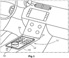
- Fig. 1 shows a perspective view of the center console of a vehicle interior in the area of the transition from the center console to the instrument panel, with a man-machine interface 11 formed in / on a housing 10 for the display and / or input of operating parameters and functions for a or several vehicle components is arranged.
- the man-machine interface 11 has a display 12 in the form of a touchscreen with a touch panel 13, which is provided with a user interface 14 with buttons 16 that can be displayed on it, a display generation layer 15 (e.g. in LCD technology) and a backlighting unit 17 is.
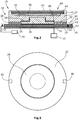
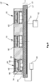
- the display 12 has an operating element unit 19 arranged on its operating surface 14 in the form of a Turntable 18, as exemplified in Fig. 2 shown, comprises a holding element 20 and a rotary element 22 rotatably mounted thereon. As indicated at 24, the holding element 20 is glued to the user interface 14.
- the rotary element 22 of the rotary actuator 18 is provided with a display device 40 which is either rigid or is arranged in the rotary actuator 18 so that it can rotate with the rotary element 22.
- the display device 40 is designed, for example, as an LCD touchscreen and has a touch panel 42, an LCD panel 44 and a backlighting unit 46.
- the display device 40 is controlled by a control and evaluation unit 48, which also evaluates the touch sensors of the touch panel 42.
- An energy supply unit 50 which is fed inductively and thus wirelessly with electrical energy, is used for the energy supply.
- the operating device has a control unit 52 which supplies a first energy transmission coil 54 with alternating voltage or alternating current.
- This first energy transfer coil 54 is, as in FIG Fig. 2 can be seen, housed within the backlighting unit 17 of the display 12.
- a second energy transmission coil 56 which is inductively coupled to the first energy transmission coil 54, is arranged in the rotary actuator 18, specifically in its rotary element 22, above the holding element 20. The energy required for operating the display device 40 and its touch panel 42 is thus transported inductively through the display 12, so that a related wiring from the housing 10 of the man-machine interface 11 to the rotary actuator 18 is not necessary.
- a PCB 58 In the rotary actuator 18 or in the rotary element 22, further electronics can optionally be accommodated on a PCB 58. These electronics can, for example, have and control a communication interface with which a connection between the turntable 18 and a corresponding communication interface in the vehicle can be established via near-field communication. But it is also conceivable that the two energy transmission coils 54.56 can be made available for data communication.
- first energy transmission coil 54 In Fig. 2 only a single first energy transmission coil 54 is shown. Alternatively, a plurality of such first energy transmission coils can be arranged on the rear side of the display 12 or within its backlighting unit 17. These first energy transmission coils 54 are arranged distributed over the surface of the display 12, so that when the rotary actuator 18, which can, for example, be detachably positioned on the display 12, is positioned at a different location, there is also inductive energy there for the operation of its display device 40 can be supplied.
- the touch control unit 12 has, in a known manner, a sensor system that is located below the control surface 14 and is, for example, capacitively sensitive.
- the signals output by the sensor system are fed to a control and evaluation unit 28, which also controls the sensor system.
- the touch sensors of the display 12 in the rotary actuator 18 can be used to determine the rotary position or to detect a push function of the rotary actuator 18. This is explained on the basis of several exemplary embodiments, it being true for all exemplary embodiments that the energy supply for the electrical / electronic components of the rotary actuator 18 is inductive and thus wireless. It should be noted at this point that the rotary position of the rotary actuator 18 can also be carried out by its own sensor system (not shown), which is built into the rotary actuator 18, in which case the data on the rotary position and, if applicable, the data that characterize a push function, be transmitted wirelessly via the energy transmission coils 54,56 or via another wireless interface.
- the rotary actuator 18 has at least one rotary position detection element 30 arranged on the underside of its rotary element 22, which for example is designed as a segment. In the application described here according to Fig. 2 the rotary element 22 is provided with two such rotary position detection elements 30.
- the two rotational position detection elements 30 move along a circular path over the user interface 14.
- the respective positions of the two rotational position detection elements 30 can be detected by the sensor system.
- the areas 32 between the rotational position detection elements 30 on the underside of the rotary element 22 (see also Fig. 3 ) cannot be sensed by the sensors. If the sensor system works capacitively, for example, at least the surface of the rotary element 22 and that of the rotary position detection elements 30 can be designed to be electrically conductive in order to use the operator's own capacitance for the potential shift sensed by the sensor system.
- FIG. 2 An exemplary embodiment is shown in which the rotational position detection elements 30 move on or in the immediate vicinity above the user interface 14. It would also be conceivable that, for example, in the case of a locally reversibly deformable user interface 14, as is the case with resistive and / or optically operating touch sensors, the rotational position detection elements 30 press against the user interface 14.
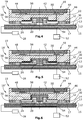
- Figs. 3 and 4th show in cross section a corresponding embodiment of such a rotary actuator 18 '. So much for those in the Figs. 3 and 4th individual components shown correspond to those of the Fig. 2 correspond, they are provided with the same reference numerals.
- the touch control unit 12 according to the Figs. 4 and 5 also works capacitively, for example.
- its rotary element 22 and its rotary position detection elements 30 are at a greater distance from the user interface 14 than in the pressed state (see in comparison FIG Figs. 4 and 5 ).
- the sensor system Based on the strength of the capacitive influence, the sensor system now recognizes whether the rotational position detection elements 30 are located directly on the user interface 14 (see FIG Fig. 5 ) or at a slight distance from it (see Fig. 4 ). This is used in the evaluation unit 28 in order to recognize that the user has or has not made an input corresponding to its rotational position by depressing the rotary element 22.
- the special feature in the embodiment of the rotary actuator 18 "according to the Figs. 6th and 7th can be seen in the fact that the push function and thus the intended input confirmation is carried out by pushing down the rotary element 22 on the basis of the detection of a push detection element 34, which is, for example, like the rotary position detection elements 30 on the underside of the rotary element 22, for example in its Center. If the sensor system responds to the approach of the pressure detection element 34 to the user interface 14 or to its contact, as is the case when the rotary actuator 18 ′′ is pressed down (see FIG Fig. 7 ), then this is an indication that the function or operator input corresponding to the rotary position of the rotary element 22 is to take place.
- a push detection element 34 which is, for example, like the rotary position detection elements 30 on the underside of the rotary element 22, for example in its Center.
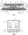
- control element unit 19 ′ can (also) have control buttons 60 instead of a rotary actuator. It is also true here that a display 40 arranged in an operating button 60 is supplied by means of inductively transmitted electrical energy, which is the subject of the invention. The key is actuated, for example, via the touch sensors of the display 12 (see, for example, the in Fig. 9 depressed control button shown on the left).
Description
Die Erfindung betrifft eine Bedienvorrichtung für eine Fahrzeugkomponente und insbesondere ein Mensch-Maschine-Interface, auch MMI oder HMI (Human-Machine-Interface) genannt, für Fahrzeuge.The invention relates to an operating device for a vehicle component and in particular a man-machine interface, also called MMI or HMI (human-machine interface), for vehicles.
Bedienvorrichtungen für Fahrzeugkomponenten sollten zur Steigerung ihrer Akzeptanz beim Benutzer über einen hohen Grad an Bedienkomfort verfügen. Bekannt sind Bedienelementeinheiten mit Tasten und/oder Drehstellern, wobei in zunehmendem Maße dazu übergegangen wird, derartige Bedienelemente mit "eigenen" Anzeigeelementen bzw. Anzeigevorrichtungen, also Displays, auszustatten. Diese Komponenten benötigen für ihren Betrieb elektrische Energie, die wegen der Aufrechterhaltung der Betriebssicherheit dauerhaft zur Verfügung stehen und daher typischerweise per Kabel zugeführt wird.Operating devices for vehicle components should have a high degree of ease of use in order to increase their acceptance by the user. Operating element units with buttons and / or rotary actuators are known, and there is an increasing trend towards equipping such operating elements with "dedicated" display elements or display devices, that is to say displays. These components require electrical energy for their operation, which is permanently available to maintain operational reliability and is therefore typically supplied by cable.
Eine batterielose Tastatur und ein batterieloses Zeigegerät (Maus) ist aus
Weitere Dateneingabe- und -übertragungsvorrichtungen sind in
Sowohl konstruktiv als auch hinsichtlich einer Reduzierung des Montageaufwands von Vorteil ist es, wenn die Energiezufuhr zu elektrischen bzw. elektronischen Komponenten von Bedienelementeinheiten in Fahrzeugen vereinfacht werden könnte, wobei eine Schwierigkeit unter anderem darin besteht, den EMV-Anforderungen bei Kraftfahrzeugen genügen zu müssen.It is advantageous both structurally and in terms of a reduction in the assembly effort if the energy supply to electrical or electronic components of control element units in vehicles could be simplified, one difficulty being, among other things, having to meet the EMC requirements in motor vehicles.
Aufgabe der Erfindung ist es daher, eine Bedienvorrichtung für eine Fahrzeugkomponente zu schaffen, deren Gehäuse mit einer insbesondere "aufgesetzten" bzw. "aufsetzbaren" Bedienelementeinheit versehen ist, deren Energiezufuhr konstruktiv vereinfacht ist.The object of the invention is therefore to create an operating device for a vehicle component, the housing of which has a particularly "attached" or "attachable" control element unit is provided, the energy supply of which is structurally simplified.
Zur Lösung dieser Aufgabe wird mit der Erfindung eine Bedienvorrichtung für eine Fahrzeugkomponente, insbesondere Mensch-Maschine-Interface (MMI - oder Human-Machine-Interface HMI) für Fahrzeuge, vorgeschlagen, wobei die Bedienvorrichtung versehen ist mit den Merkmalen des Anspruchs 1.To solve this problem, the invention proposes an operating device for a vehicle component, in particular a human-machine interface (MMI or human-machine interface HMI) for vehicles, the operating device being provided with the features of claim 1.
Einzelne Ausgestaltungen der Erfindung sind Gegenstand der Unteransprüche.Individual refinements of the invention are the subject of the subclaims.
Im Folgenden wird die Erfindung anhand der Beispiele einer Anzeigevorrichtung bzw. eines Anzeigeelements und/oder einer Funktionssensorik (Drück-, Dreh-, Force-Sense-, Force-Feedback-Funktion) als elektrischer Verbraucher beschrieben. Das allerdings soll den Umfang der Erfindung nicht einschränken.The invention is described below using the examples of a display device or a display element and / or a functional sensor system (push, turn, force-sense, force-feedback function) as electrical consumers. However, this is not intended to limit the scope of the invention.
Nach der Erfindung ist also vorgesehen, die für den Betrieb der Bedieneinheit erforderliche elektrische Energie induktiv in eine Energieversorgungseinheit der Bedienelementeinheit einzuspeisen. Damit erfolgt die Energiezufuhr drahtlos, was den Konstruktions- und Montageaufwand der Bedienvorrichtung reduziert. Insbesondere ist es nun möglich, eine mit elektrischer Energie zu versorgende Bedienelementeinheit an der Vorderseite des Gehäuses auch abnehmbar positionieren zu können. Dies kann unter Umständen auch aus sicherheitstechnischen Aspekten geschehen, um nämlich einen unautorisierten Zugang zum Fahrzeug wenig attraktiv erscheinen zu lassen, da trotz unautorisiertem Zugang zum Fahrzeug dessen Betrieb entweder gar nicht oder nur eingeschränkt möglich ist.According to the invention, it is provided that the electrical energy required for operating the operating unit is inductively fed into an energy supply unit of the operating element unit. The energy is thus supplied wirelessly, which reduces the construction and assembly costs of the operating device. In particular, it is now possible to be able to position a control element unit to be supplied with electrical energy on the front of the housing in a removable manner. Under certain circumstances, this can also be done for security reasons, namely to make unauthorized access to the vehicle appear less attractive, since, despite unauthorized access to the vehicle, its operation is either not possible at all or only to a limited extent.
Die Energieversorgung der Bedienelementeinheit könnte sicherlich auch dadurch erfolgen, dass die Bedienelementeinheit über eine auswechselbare Batterie oder einen an ein Ladegerät anschließbaren wiederaufladbaren Akku verfügt. Durch die erfindungsgemäße induktive Energieeinspeisung jedoch wird stets garantiert, dass die Bedienelementeinheit über ausreichend elektrische Energie verfügt, ohne dass der Fahrer für das Auswechseln der Batterie oder das Laden des Akkus Sorge tragen muss.The operating element unit could certainly also be supplied with energy in that the operating element unit has a replaceable battery or a rechargeable battery that can be connected to a charger. However, the inductive energy supply according to the invention always guarantees that the control element unit has sufficient electrical energy without the driver having to worry about changing the battery or charging the rechargeable battery.
Erfindungsgemäß befindet sich eine erste (Energieübertragungs-)Spule im Gehäuse, und zwar der Rückseite der Vorderwand des Gehäuses zugewandt, während eine zweite (Energieübertragungs-)Spule in der Bedienelementeinheit angeordnet ist. Es ist auch denkbar, dass das Gehäuse mit mehreren ersten Spulen versehen ist, die nebeneinander angeordnet sind, so dass je nach Positionierung der in diesem Falle abnehmbar ausgeführten Bedienelementeinheit auf der Vorderwand des Gehäuses die zweite Spule von einer der ersten Spulen mit Energie versorgt wird, um elektrische Energie in die zweite Spule induktiv einzuspeisen. Die ersten Spulen können kodiert sein, so dass die Bedienvorrichtung Informationen darüber erlangt, welche der ersten Spulen aktuell die Bedienelementeinheit mit elektrischer Energie versorgt bzw. mit ihr kommuniziert. Dadurch lässt sich z.B. auf einem Display, welches die Vorderseite des Gehäuses bildet, und an dem die Bedienelementeinheit positionierbar ist, entsprechend unterschiedliche Anzeigeinhalte wiedergeben.According to the invention, a first (energy transmission) coil is located in the housing, specifically facing the rear of the front wall of the housing, while a second (energy transmission) coil is arranged in the operating element unit. It is also conceivable that the housing is provided with several first coils, which are arranged next to one another, so that depending on the positioning of the removable control element unit on the front wall of the housing, the second coil is supplied with energy by one of the first coils, to induct electrical energy into the second coil to feed. The first coils can be coded so that the operating device obtains information about which of the first coils is currently supplying the operating element unit with electrical energy or communicating with it. In this way, for example, on a display which forms the front of the housing and on which the operating element unit can be positioned, correspondingly different display contents can be reproduced.
Erfindungsgemäß ist die Vorderwand des Gehäuses mit einem Display versehen. Bei diesem Display kann es sich um einen Touchscreen handeln. Das Display kann beispielsweise ein LCD-, ein LED-, ein Micro-LED-, ein OLED-, ein Q-Dot- oder aber auch ein E-Ink-Display sein. Von Bedeutung insoweit ist, dass grundsätzlich sämtliche "aktiven" Displaytypen verwendet werden können, solange ihr Aufbau über keinerlei zwischen der Vorder- und der Rückseite des Displays angeordnete induktive vollständige Abschirmung wie beispielsweise eine durchgehende Metallisierungsschicht o.dgl. verfügt, welche für den Betrieb des jeweiligen Displaytyps auch nicht zwingend erforderlich sind.According to the invention, the front wall of the housing is provided with a display. This display can be a touchscreen. The display can be, for example, an LCD, an LED, a micro-LED, an OLED, a Q-dot or also an e-ink display. It is important in this respect that in principle all "active" display types can be used as long as their structure does not have any inductive complete shielding, such as a continuous metallization layer or the like, arranged between the front and rear of the display. which are not absolutely necessary for the operation of the respective display type.
Es hat sich überraschenderweise herausgestellt, dass man durch ein LCD-Display hindurch induktiv elektrische Energie transportieren kann, um damit eine an der Vorderseite des Displays angeordnete Bedienelementeinheit betreiben zu können, wobei der Bildinhalt des Displays, durch welches die Ladung induktiv transportiert wird, visuell unbeeinflusst bleibt. Dabei kann man sich z. B. den Qi-Ladestandard für Mobiltelefone zunutze machen.It has surprisingly been found that electrical energy can be transported inductively through an LCD display in order to be able to operate a control element unit arranged on the front of the display, the image content of the display through which the charge is inductively transported being visually unaffected remain. You can z. B. make use of the Qi charging standard for cell phones.
Es ist ferner möglich, die induktiv gekoppelten Spulen neben der Energieversorgung auch für die Datenkommunikation einzusetzen. So wäre es beispielsweise möglich, nach dem Start des Fahrzeugs und nach der Aktivierung der induktiven Energieübertragung zur der Bedienelementeinheit durch diese bzw. durch eine in dieser befindliche Elektronik rückzumelden, wenn ein Energie-Harvesting-IC o.dgl. Schaltkreis meldet, dass ausreichend Energie für den Betrieb der Bedienelementeinheit übertragen worden ist. Die Datenkommunikation kann uni- oder bidirektional erfolgen (z.B. gemäß dem NFC-Standard), um beispielsweise auf der Anzeigevorrichtung bzw. durch das Anzeigeelement der Bedienelementeinheit gewünschte Informationen anzuzeigen.It is also possible to use the inductively coupled coils not only for power supply but also for data communication. For example, it would be possible, after starting the vehicle and after activating the inductive energy transmission to the control element unit, to report back through it or through electronics located in it, if an energy harvesting IC or the like. Circuit reports that sufficient energy has been transferred to operate the control unit. The data communication can be unidirectional or bidirectional (eg according to the NFC standard) to for example, to display desired information on the display device or by the display element of the operating element unit.
Ein Anwendungsbereich der Erfindung betrifft beispielsweise eine Bedienvorrichtung mit einem Display, an dem ein Drehsteller bzw. Dreh-Drücksteller einer Bedienelementeinheit angeordnet ist, über den beispielsweise die Temperaturvorgabe für die Klimaanlage des Fahrzeugs erfolgen kann. Durch Drehen des Drehstellers wird die gewünschte Temperatur eingestellt, wobei die aktuell eingestellte Temperatur durch das Anzeigeelement bzw. die Anzeigevorrichtung der Bedienelementeinheit angezeigt wird. Eine entsprechend erforderliche Sensorik (z.B. kapazitiv, optisch oder resistiv arbeitend) wäre dann in der Bedienelementeinheit vorzusehen. Alternativ könnte die Sensorik eines als Touchscreen ausgeführten Displays genutzt werden, was weiter unten noch im Detail beschrieben werden wird.One area of application of the invention relates, for example, to an operating device with a display on which a rotary actuator or rotary-push actuator of an operating element unit is arranged, via which, for example, the temperature specification for the air conditioning system of the vehicle can take place. The desired temperature is set by turning the rotary switch, the currently set temperature being displayed by the display element or the display device of the operating element unit. A correspondingly required sensor system (e.g. capacitive, optical or resistive) would then have to be provided in the operating element unit. Alternatively, the sensor system of a display designed as a touchscreen could be used, which will be described in detail below.
In weiterer vorteilhafter Ausgestaltung der Erfindung kann vorgesehen sein, dass die mindestens eine erste Spule oder mindestens eine der ersten Spulen und die mindestens eine zweite Spule oder mindestens eine der zweiten Spule ferner zur drahtlosen uni-oder bidirektionalen Datenkommunikation zwischen der Ansteuer- und Auswerteeinheit der Bedienelementeinheit und einer außerhalb der Bedienelementeinheit und insbesondere an und/oder in dem Gehäuse angeordneten Signal- und Datenverarbeitungseinheit oder einen Kommunikationsinterface vorgesehen sind.In a further advantageous embodiment of the invention, it can be provided that the at least one first coil or at least one of the first coils and the at least one second coil or at least one of the second coil also for wireless unidirectional or bidirectional data communication between the control and evaluation unit of the control element unit and a signal and data processing unit or a communication interface arranged outside the operating element unit and in particular on and / or in the housing are provided.
Bei einer weiteren Ausgestaltung der Erfindung kann vorgesehen sein, dass die Bedienelementeinheit mit einem Nahfeld-Signalübertragungsinterface zur drahtlosen Kommunikation mit einem außerhalb der Bedienelementeinheit und außerhalb des Gehäuses befindlichen Kommunikationsinterface versehen ist. Hierbei ist vorgesehen, dass die Bedienelementeinheit über ein Nahfeld-Signalübertragungsinterface wie beispielsweise eine Bluetooth-Schnittstelle verfügt, über die die Datenkommunikation mit einem korrespondierenden Kommunikationsinterface erfolgt, das außerhalb der Bedienelementeinheit und außerhalb des Gehäuses der Bedienvorrichtung, also an anderer Stelle im Fahrzeug angeordnet ist. Über eine derartige drahtlose Kommunikationsverbindung könnte dann eine höherratige Datenkommunikation erfolgen, als dies unter Verwendung der Energieübertragungsspulen der Fall sein könnte.In a further embodiment of the invention it can be provided that the control element unit is provided with a near-field signal transmission interface for wireless communication with a communication interface located outside the control element unit and outside the housing. It is provided here that the control element unit has a near-field signal transmission interface such as a Bluetooth interface, via which the data communication takes place with a corresponding communication interface that is outside the control element unit and outside the housing of the control device, i.e. elsewhere in the vehicle is arranged. A higher-rate data communication could then take place via such a wireless communication link than could be the case using the energy transmission coils.
In weiterer vorteilhafter Ausgestaltung der Erfindung kann vorgesehen sein, dass die Bedienelementeinheit mindestens eine Bedientaste, vorzugsweise eine Bedientastenleiste oder ein Bedientastenfeld mit jeweils mehreren Bedientasten, und/oder einen Drehsteller, insbesondere mit Dreh- und Drückfunktion, und/oder ein Touchpad zur Dateneingabe aufweist und/oder dass das Anzeigeelement bzw. die Anzeigevorrichtung der Bedienelementeinheit als Touchscreen ausgeführt ist.In a further advantageous embodiment of the invention, it can be provided that the control element unit has at least one control button, preferably a control button strip or a control keypad with several control buttons each, and / or a rotary actuator, in particular with a rotary and push function, and / or a touchpad for data input and / or that the display element or the display device of the operating element unit is designed as a touchscreen.
Zweckmäßig kann es ferner sein, wenn die Vorderseite des Gehäuses ein Display aufweist, wobei die Bedienelementeinheit auf und/oder vor dem Display positioniert und/oder positionierbar ist.It can also be expedient if the front of the housing has a display, the operating element unit being positioned and / or positionable on and / or in front of the display.
Schließlich ist es zweckmäßig, wenn das Display des Gehäuses eine Hinterleuchtungseinheit mit einer Lichtabgabefläche aufweist, die der Rückseite des Displays zugewandt ist, wobei die mindestens eine erste Spule in der Hinterleuchtungseinheit angeordnet ist.Finally, it is expedient if the display of the housing has a backlighting unit with a light emission surface facing the rear of the display, the at least one first coil being arranged in the backlighting unit.
Schließlich ist es auch möglich, die Bedienelementeinheit mit einer Force-Feedback-Funktionalität oder mit einer Force-Sense-Force-Feedback-Funktionalität in der Bedienelementeinheit selbst zu versehen. Die Bedienelementeinheit kann reversibel abnehmbar positionierbar sein (z.B. durch Adhäsionskleber, Gel, Saugnapf etc.) oder dauerhaft positioniert sein.Finally, it is also possible to provide the operating element unit with a force feedback functionality or with a force sense force feedback functionality in the operating element unit itself. The control element unit can be reversibly and detachably positioned (e.g. by means of adhesive glue, gel, suction cup, etc.) or it can be positioned permanently.
Wie bereits oben erwähnt, kann es von Vorteil sein, wenn das Display als Touchscreen ausgeführt ist, der ein kapazitiv und/oder resistiv und/oder optisch arbeitendes Touch-Panel aufweist, wobei die Bedienelementeinheit vor und/oder auf dem Touch-Panel angeordnet ist. Wird ein Display mit Touchfunktion, also ein berührungssensitives Display eingesetzt, so ist es zweckmäßig, wenn eine manuelle Betätigung der Bedienelementeinheit mittels des Touchpad des Displays sensierbar ist.As already mentioned above, it can be advantageous if the display is designed as a touchscreen which has a capacitive and / or resistive and / or optical touch panel, the operating element unit being arranged in front of and / or on the touch panel . If a display with a touch function, i.e. a touch-sensitive display, is used, it is useful to if a manual actuation of the control element unit can be sensed by means of the touchpad of the display.
Die Bedienelementeinheit kann also beispielsweise mit einer Funktionssensorik oder mit einer Anzeigevorrichtung oder mit beidem versehen sein und kann auf einer Gehäusewand ohne oder mit Anzeigefunktion (Display) angeordnet sein. In sämtlichen zuvor genannten Fällen ist das erfindungswesentliche Merkmal darin zu sehen, dass ein elektrischer Verbraucher der Bedienelementeinheit induktiv und durch die Gehäusewand hindurch mit elektrischer Energie versorgt wird.The operating element unit can therefore be provided, for example, with a function sensor system or with a display device or with both and can be arranged on a housing wall with or without a display function (display). In all of the aforementioned cases, the essential feature of the invention is to be seen in the fact that an electrical consumer of the operating element unit is supplied with electrical energy inductively and through the housing wall.
Zur Erläuterung der Vorteile dieser Ausgestaltung der Erfindung sei gesagt, dass der Innenraum von Fahrzeugen in zunehmendem Maße mit Schaltflächen aufweisenden Touch-Bedieneinheiten ausgestattet wird, über die verschiedene Fahrzeugkomponenten bedient werden können. Andererseits erfreuen sich aber auch sogenannte Drehsteller zur Eingabe und Eingabebestätigung von Betriebsparametern und Bedienfunktionen für Fahrzeugkomponenten zunehmender Beliebtheit. Zur Detektion der aktuellen Drehstellerposition sowie der Eingabebestätigung weisen bekannte Drehsteller eine mitunter recht aufwendig konstruierte Sensorik auf, was die Herstellungskosten erhöht. Wird ein Drehsteller mit benachbart zu diesem angeordneter Touch-Bedieneinheit eingesetzt, so handelt es sich bei beiden um zwei voneinander getrennte Komponenten mit insoweit auch voneinander getrennten Oberflächen.To explain the advantages of this embodiment of the invention, it should be said that the interior of vehicles is increasingly being equipped with touch control units which have buttons and which can be used to operate various vehicle components. On the other hand, so-called rotary actuators for inputting and confirming input of operating parameters and operating functions for vehicle components are also enjoying increasing popularity. For the detection of the current turntable position as well as the input confirmation, known turntables have a sensor system that is sometimes very complex, which increases the manufacturing costs. If a rotary actuator is used with a touch control unit arranged adjacent to it, then both are two separate components with surfaces that are separate from one another.
Insoweit also von Vorteil ist, es, wenn die Bedienvorrichtung für eine Fahrzeugkomponente versehen ist mit
- einer mit manuell betätigbaren Schaltflächen versehbaren Touch-Bedieneinheit, die eine berührungs- und/oder drucksensitive Bedienoberfläche und eine unterhalb dieser angeordnete Sensorik zur Erkennung der Position einer Berührung der und/oder einer Druckausübung auf die Bedienoberfläche aufweist,
- einer mit der Sensorik in Wirkverbindung stehenden Auswerteeinheit zum Empfang von Signalen von der Sensorik und zur Auswertung dieser Signale zur Erkennung einer manuellen Betätigung der Bedienoberfläche sowie zur Auslösung einer durch die Position der Betätigung auf der Bedienoberfläche definierten Bedienfunktion und
- einem Drehsteller, der ein Haltelement und ein an diesem drehbar angeordnetes, manuell betätigbares Drehelement aufweist,
- wobei das Halteelement in einem Teilbereich der Bedienoberfläche der Touch-Bedieneinheit angeordnet ist und mindestens ein von der dem besagten Teilbereich der Bedienoberfläche zugeordneten Sensorik erfassbares Drehstellungs-Detektionselement zur an einer Position im besagten Teilbereich erfolgenden Berührung der und/oder Druckausübung auf die Bedienoberfläche aufweist und
- wobei die Auswerteeinheit anhand von von der Sensorik empfangenen Signalen eine Betätigung der Bedienoberfläche der Touch-Bedieneinheit durch das mindestens eine Drehstellungs-Detektionselement des Drehelements des Drehstellers erkennt und anhand der Position des mindestens einen Drehstellungs-Detektionselements eine dieser Position zugeordnete Bedienfunktion auslöst.
- a touch control unit which can be provided with manually operable buttons and which has a touch and / or pressure sensitive control surface and a sensor system arranged below it for detecting the position of a touch and / or an exertion of pressure on the control surface,
- an evaluation unit in operative connection with the sensor system for receiving signals from the sensor system and for evaluating these signals for recognizing manual actuation of the user interface and for triggering an operating function defined by the position of the actuation on the user interface and
- a turntable which has a holding element and a manually operable rotary element which is rotatably arranged thereon,
- wherein the holding element is arranged in a partial area of the user interface of the touch control unit and has at least one rotational position detection element detectable by the sensor system assigned to said partial area of the user interface for touching and / or exerting pressure on the user interface at a position in said partial area and
- The evaluation unit recognizes an actuation of the user interface of the touch control unit by the at least one rotary position detection element of the rotary element of the rotary actuator based on signals received from the sensor system and triggers an operating function assigned to this position based on the position of the at least one rotary position detection element.
Mit dieser Weiterbildung der Erfindung wird also sinngemäß vorgeschlagen, den Drehsteller oder allgemeiner gesagt die Bedienelementeinheit dann, wenn diese selbst nicht über eine Funktionssensorik verfügt, in die Touch-Bedieneinheit insofern einzubinden, als deren Sensorik zur Erkennung der aktuellen Drehsteller-Verstellposition genutzt wird. Dazu wird nach der Erfindung auf bzw. oberhalb einer manuell betätigbaren Touch-Bedieneinheit mit einer berührungs- und/oder drucksensitiven Bedienoberfläche und einer unterhalb dieser angeordneten Sensorik ein Drehsteller angeordnet, der ein Halteelement und ein an diesem drehbar angeordnetes, manuell betätigbares Drehelement aufweist. Das Drehelement ist mit mindestens einem DrehstellungsDetektionselement versehen, dass sich beim Verdrehen des Drehelements über bzw. auf der Bedienoberfläche der Touch-Bedieneinheit bewegt. Die jeweilige Position des Drehstellungs-Detektionselements kann nun durch die Sensorik der Touch-Bedieneinheit erfasst werden. Auf entsprechende Weise kann auch das Drücken einer Bedientaste der Bedienelementeinheit durch die Sensorik des Touchscreens erkannt werden, wobei die Erkennung der Betätigung auf dem Touchscreen ortsaufgelöst erfolgt.With this development of the invention, it is proposed, in general, to integrate the turntable or, more generally, the control element unit into the touch control unit, if it does not itself have a function sensor system, so that its sensor system is used to detect the current turntable adjustment position. For this purpose, according to the invention, a rotary actuator is arranged on or above a manually operable touch control unit with a touch and / or pressure-sensitive operator interface and a sensor system arranged below it, which has a holding element and a manually operable rotary element arranged rotatably on it. The rotary element is provided with at least one rotary position detection element that moves over or on the user interface of the touch control unit when the rotary element is rotated. The respective position of the rotational position detection element can now be detected by the sensor system of the touch control unit. In a corresponding manner, pressing a control button of the control element unit can also be done by the sensor system of the Touchscreens are detected, the detection of the actuation on the touchscreen being carried out in a spatially resolved manner.
In demjenigen Bereich der Bedienoberfläche der Touch-Bedieneinheit, in dem das Halteelement des Drehstellers angeordnet ist, können weiterhin durchaus noch Symbolfelder bzw. Schaltflächen zur manuellen Eingabe von Bedienfunktionen angezeigt bzw. vorgesehen werden. Beispielsweise kann der Drehsteller als Ring realisiert sein, so dass durch das Innere des Rings die Bedienoberfläche der Touch-Bedieneinheit visuell zugänglich wäre. Alternativ könnte man die Informationen der Bedienoberfläche der Touch-Bedieneinheit innerhalb des Rings über optische Lichtleitelemente, wie beispielsweise optische Lichtfaserbausteine zur Oberfläche des Drehstellers leiten. Derartige Eingabefelder bzw. Anzeigefelder können aber sehr wohl auf der Bedienoberfläche der Touch-Bedieneinheit außerhalb des zuvor genannten Bereichs dargestellt werden, so dass die erfindungsgemäße Touch-Bedieneinheit sowohl wie herkömmlich durch Berührung bzw. Druckausübung mit dem Finger einer Hand als auch durch Verstellen des Drehstellers bedient werden kann.In that area of the user interface of the touch control unit in which the retaining element of the rotary actuator is arranged, symbol fields or buttons for the manual input of control functions can still be displayed or provided. For example, the rotary actuator can be implemented as a ring, so that the user interface of the touch control unit would be visually accessible through the inside of the ring. Alternatively, the information on the user interface of the touch control unit within the ring could be routed to the surface of the turntable via optical light guide elements, such as optical fiber optic modules. Such input fields or display fields can, however, be displayed on the user interface of the touch control unit outside the aforementioned area, so that the touch control unit according to the invention can be used both as conventionally by touching or exerting pressure with the finger of a hand and by adjusting the rotary actuator can be operated.
Das Halteelement des Drehstellers kann beispielsweise durch Kleben auf der Bedienoberfläche angebracht sein. Es ist aber ebenso denkbar, dass das Halteelement, ohne direkt an der Bedienoberfläche fixiert zu sein, auf dieser angeordnet ist; in diesem Fall ist das Halteelement z.B. an einem Rahmen o.dgl. die Touch-Bedieneinheit umgebenden bzw. daran angrenzenden Element befestigt. Das Drehelement kann als Drehring bzw. als Drehknopf mit oder ohne zusätzliche Betätigungs- und/oder Anzeigeelemente und/oder mit oder ohne ein Touchpad ausgebildet sein.The holding element of the turntable can be attached to the user interface, for example by gluing. However, it is also conceivable that the holding element, without being fixed directly to the user interface, is arranged thereon; in this case the holding element is, for example, on a frame or the like. the touch control unit surrounding or attached to the element adjoining it. The rotary element can be designed as a rotary ring or as a rotary knob with or without additional actuation and / or display elements and / or with or without a touchpad.
Als Touch-Bedieneinheit eignet sich eine Bedieneinheit mit kapazitiv, resistiv oder optisch arbeitender Sensorik. Im Falle einer kapazitiv arbeitenden Sensorik ist das manuell zu betätigende Drehelement und das mindestens eine Drehstellungs-Detektionselement elektrisch leitfähig ausgeführt, so dass die Eigenkapazität des Bedieners über das Drehelement und das Drehstellungs-Detektionselement die Potenzialverteilung in der Sensorik beeinflusst. Alternativ können drucksensitiv arbeitende Touch-Bedieneinheiten eingesetzt werden. Diese Touch-Bedieneinheiten sind lokal reversibel deformierbar, wobei der Ort der Deformation resistiv oder optisch (durch sogenannte FTIR Sensoren - Frustrated Total Internal Reflection) erkannt wird.A control unit with capacitive, resistive or optical sensors is suitable as a touch control unit. In the case of a capacitive sensor system, the manually operated rotary element and the at least one rotary position detection element are designed to be electrically conductive, so that the operator's own capacitance via the rotary element and the rotary position detection element influences the potential distribution in the sensor system. Alternatively pressure-sensitive touch control units can be used. These touch control units are locally reversibly deformable, with the location of the deformation being detected resistively or optically (by so-called FTIR sensors - Frustrated Total Internal Reflection).
Durch die erfindungsgemäß vorgesehene Integration der Bedienelementeinheit in Form z.B. mindestens eines Drehstellers auf der Bedienoberfläche einer Touch-Bedieneinheit bedarf es nun keiner Separation der Oberflächen mehr. Es ist eine beliebige Positionierung und Dimensionierung des bzw. der Drehsteller möglich, ohne die Touch-Bedieneinheit verändern zu müssen. Die Auswertung der Drehsteller-Verstellposition erfolgt über die bei der Touch-Bedieneinheit vorhandenen Sensorik, die die (Dreh-)Position des mindestens eines Drehstellungs-Detektionselements, das sich beim Verstellen des Drehstellers auf einer Kreisbahn bewegt, erkennt, so dass für den Drehsteller keine separate Auswerteelektronik erforderlich ist, sondern die Auswerteelektronik genutzt werden kann, die für die manuelle Betätigung von Touch-Bedieneinheiten bereits vorhanden ist.As a result of the integration of the operating element unit in the form of, for example, at least one rotary actuator on the operating surface of a touch operating unit, there is no longer any need to separate the surfaces. Any positioning and dimensioning of the rotary actuator (s) is possible without having to change the touch control unit. The evaluation of the rotary actuator adjustment position is carried out using the sensors present on the touch control unit, which detect the (rotary) position of the at least one rotary position detection element that moves on a circular path when the rotary actuator is adjusted, so that none of the rotary actuator separate evaluation electronics is required, but the evaluation electronics can be used that are already available for the manual operation of touch control units.
In weiterer vorteilhafter Ausgestaltung der Erfindung kann ferner vorgesehen sein, dass bei einer manuellen Betätigung einer Schaltfläche der Touch-Bedieneinheit eine akustische, optische und/oder taktile Rückmeldung erfolgt. Derartige Systeme sind als Force Feedback bekannt. Die diesbezügliche akustische, optische und/oder taktile Rückmeldung muss nicht zwingend auch dann erfolgen, wenn eine Bedienfunktion über das Drehelement angewählt wird. Die Eingabe eines Befehls über das Drehelement kann dann beispielsweise durch Niederdrücken des Drehelements erfolgen und ist somit für den Bediener einfach "erkennbar".In a further advantageous embodiment of the invention, provision can also be made for an acoustic, optical and / or tactile feedback to occur when a button on the touch control unit is actuated manually. Such systems are known as force feedback. The related acoustic, optical and / or tactile feedback does not necessarily have to take place when an operating function is selected via the rotary element. A command can then be input via the rotary element, for example, by depressing the rotary element and is thus easily "recognizable" for the operator.
Diesbezüglich kann es von Vorteil sein, wenn das Drehelement an dem Halteelement in Richtung auf die Bedienoberfläche der Touch-Bedieneinheit reversibel bewegbar und/oder reversibel gegen die Bedienoberfläche der Touch-Bedieneinheit drückbar angeordnet ist, wobei die Auswerteeinheit eine Betätigung der Bedienoberfläche mittels des mindestens einem Drehstellungs-Detektionselements des Drehelements in dessen in Richtung auf die Bedienoberfläche bewegten und/oder gegen die Bedienoberfläche gedrückten Zustand erkennt. Durch das Niederdrücken des Drehelements zur Eingabe eines Befehls über das Drehelement nähert sich das Drehstellungs-Detektionselement der Bedienoberfläche der Touch-Bedieneinheit an, was die Sensorik der Touch-Bedieneinheit anhand unterschiedlicher Signalstärken erkennt. Handelt es sich bei der Touch-Bedieneinheit um eine resistive oder optisch arbeitende Bedieneinheit mit lokal elastisch verformbarer Bedienoberfläche, so kann die Sensorik auch dann unterschiedlich große Signalstärken detektieren und damit eine Drückfunktion erkennen, wenn mittels des Drehstellungs-Detektionselements gegen die Bedienoberfläche gedrückt wird. Ab einem Mindestdruck bzw. einer Mindestandrückkraft erfolgt die Erkennung, dass das Drehelement gedrückt ist. Damit wird die entsprechende Funktionseingabe akzeptiert.In this regard, it can be advantageous if the rotary element is arranged on the holding element in the direction of the user interface of the touch control unit so that it can be reversibly moved and / or reversibly pressed against the user interface of the touch control unit, the evaluation unit actuating the user interface by means of the at least one Rotation position detection element of the rotary element detects in its state moved in the direction of the user interface and / or pressed against the user interface. By pressing down the rotary element to input a command via the rotary element, the rotary position detection element approaches the user interface of the touch control unit, which the sensor system of the touch control unit recognizes on the basis of different signal strengths. If the touch control unit is a resistive or optically operating control unit with a locally elastically deformable user interface, the sensor system can also detect signal strengths of different sizes and thus recognize a push function when the user is pressed against the user interface using the rotary position detection element. From a minimum pressure or a minimum pressing force, it is recognized that the rotary element is pressed. This means that the corresponding function input is accepted.
Insoweit kann es also von Vorteil sein, wenn das Drehelement ein Drück-Detektionselement zur Berührung der und/oder Annäherung an die Bedienoberfläche und/oder zur Druckausübung auf die Bedienoberfläche der Touch-Bedieneinheit beim Drücken des Drehelements aufweist, wobei die Auswerteeinheit den gedrückten Zustand anhand eines Signals der Sensorik bei durch das Drück-Detektionselement erfolgender Berührung der und/oder zumindest Annäherung an die Bedienoberfläche und/oder Druckausübung auf die Bedienoberfläche der Touch-Bedieneinheit erkennt.In this respect, it can be advantageous if the rotary element has a pressure detection element for touching and / or approaching the user interface and / or for exerting pressure on the user interface of the touch control unit when the rotary element is pressed, the evaluation unit based on the pressed state a signal of the sensor system when the pressure detection element touches and / or at least approaches the user interface and / or exerts pressure on the user interface of the touch control unit.
In weiterer vorteilhafter Ausgestaltung der Erfindung kann vorgesehen sein, dass die Sensorik der Touch-Bedieneinheit bei Berührung der und/oder Annäherung an die Bedienoberfläche an einer Position ein anderes Signal ausgibt als bei Druckausübung auf die Bedienoberfläche der Touch-Bedieneinheit an der besagten Position. Alternativ bzw. zusätzlich kann die Sensorik bei Druckausübung auf die Bedienoberfläche der Touch-Bedieneinheit an einer Position ein Signal mit einer von der Größe des Drucks abhängigen Signalstärke ausgeben. In all diesen Fällen erkennt die Auswerteeinheit anhand dieser Signale, ob das Drehelement gedrückt ist oder nicht.In a further advantageous embodiment of the invention it can be provided that the sensor system of the touch control unit outputs a different signal when touching and / or approaching the user interface at a position than when pressure is exerted on the user interface of the touch control unit at the said position. Alternatively or additionally, when pressure is exerted on the user interface of the touch control unit, the sensor system can output a signal at a position with a signal strength that is dependent on the magnitude of the pressure. In all these cases, the evaluation unit recognizes on the basis of these signals whether the rotary element is pressed or not.
Wie bereits oben dargelegt, ist das Halteelement des Drehstellers auf der Bedienoberfläche angeordnet und zwar gegen ungewollte Verschiebungen gesichert. Beispielsweise ist es möglich, dass das Halteelement auf der Bedienoberfläche aufliegend an dieser fixiert ist. Diese Kontaktierung der Bedienoberfläche wird entweder von der Sensorik ignoriert oder aber der Bereich der Bedienoberfläche, in dem das Halteelement fixiert ist, ist frei von einer Sensorik.As already explained above, the holding element of the rotary actuator is arranged on the user interface and is secured against unwanted displacement. For example, it is possible for the holding element to be fixed on the user interface while resting on the user interface. This contacting of the user interface is either ignored by the sensor system or the area of the user interface in which the holding element is fixed is free of a sensor system.
Alternativ ist es auch möglich, dass das Haltelement des Drehstellers bzw. der Drehsteller selbst verschiebbar auf der Bedienoberfläche angeordnet ist, um mit dem Drehsteller verschiedene Schaltflächen anzufahren, um dann durch Verdrehung des Drehelements des Drehstellers eine Eingabefunktion auszuüben. Die Fixierung des Drehstellers erfolgt dabei beispielsweise mechanisch.Alternatively, it is also possible that the holding element of the rotary actuator or the rotary actuator itself is arranged displaceably on the user interface in order to approach various buttons with the rotary actuator in order to then exercise an input function by rotating the rotary element of the rotary actuator. The turntable is fixed mechanically, for example.
Die zuvor anhand eines Dreh-(Drück-)Stellers (mit Display) als Beispiel für ein Bedienelement der Bedieneinheit beschriebenen Ausgestaltungen der Erfindung gelten entsprechend auch für Bedientasten (mit Display).The embodiments of the invention previously described using a rotary (push) actuator (with display) as an example of an operating element of the operating unit also apply accordingly to operating buttons (with display).
Schließlich ist es denkbar, dass das Drehelement rastend oder freilaufend drehbar an dem Halteelement angeordnet ist.Finally, it is conceivable for the rotary element to be arranged on the holding element in a latching or free-running rotatable manner.
Die Erfindung wird nachfolgend anhand verschiedener Ausführungsbeispiele und unter Bezugnahme auf die Zeichnung näher erläutert. Im Einzelnen zeigen dabei:
- Fig. 1
- eine perspektivische Ansicht auf den vorderen Bereich der Mittelkonsole eines Fahrzeugs mit auf der Mittelkonsole angeordneter TouchBedieneinheit 12 die manuell betätigbare Schaltflächen und einen Drehsteller aufweist,
- Fig. 2
- einen Schnitt durch die Touch-Bedieneinheit im Bereich des Drehstellers gemäß II-II der
Fig. 1 , - Fig. 3
- eine Ansicht auf die Unterseite des Drehstellers gemäß
Fig. 2 , - Fign. 4 und 5
- ein weiteres Ausführungsbeispiel eines auf der Bedienoberfläche einer Touch-Bedieneinheit angeordneten Drehstellers, der zur Bestätigung einer Eingabe niederdrückbar ist,
- Fign. 6 und 7
- ein weiteres Ausführungsbeispiel eines auf der Bedienoberfläche einer Touch-Bedieneinheit angeordneten Drehstellers, der zur Bestätigung einer Eingabe niederdrückbar ist, und
- Fign.8 und 9
- ein weiteres Ausführungsbeispiel in Ansicht und im Schnitt.
- Fig. 1
- a perspective view of the front area of the center console of a vehicle with the
touch control unit 12, which is arranged on the center console and has manually operated buttons and a rotary actuator, - Fig. 2
- a section through the touch control unit in the area of the rotary actuator according to II-II of
Fig. 1 , - Fig. 3
- a view of the underside of the turntable according to
Fig. 2 , - Figs. 4 and 5
- Another embodiment of a rotary actuator arranged on the user interface of a touch control unit, which can be depressed to confirm an input,
- Figs. 6 and 7
- a further exemplary embodiment of a rotary actuator which is arranged on the user interface of a touch control unit and which can be depressed to confirm an input, and
- Figures 8 and 9
- another embodiment in view and in section.
Im Folgenden wird die Erfindung, nämlich die drahtlose Versorgung der elektrischen/elektronischen Komponenten einer auf ein Display aufgesetzten Bedienelementeinheit anhand eines Drehstellers bzw. Dreh-/Drückstellers beschrieben, dessen Drehposition und gegebenenfalls Drückfunktion ferner durch eine Touch-Sensorik des Displays erkannt wird, was aber für die Erfindung nicht zwingend erforderlich, ggf. aber vorteilhaft ist.In the following, the invention, namely the wireless supply of the electrical / electronic components of a control element unit placed on a display, is described using a rotary actuator or rotary / push button whose rotary position and, if applicable, push function is also recognized by a touch sensor system of the display is not absolutely necessary for the invention, but may be advantageous.
Erfindungsgemäß ist das Drehelement 22 des Drehstellers 18 mit einer Anzeigevorrichtung 40 versehen, die entweder starr oder mit dem Drehelement 22 mitdrehbar im Drehsteller 18 angeordnet ist. Die Anzeigevorrichtung 40 ist beispielsweise als LCD-Touchscreen ausgebildet und weist ein Touch-Panel 42, ein LCD-Panel 44 und eine Hinterleuchtungseinheit 46 auf. Die Anzeigevorrichtung 40 wird von einer Ansteuer- und Auswerteeinheit 48 angesteuert, die auch die Auswertung der Touch-Sensorik des Touch-Panels 42 vornimmt.According to the invention, the
Zur Energieversorgung dient eine Energieversorgungseinheit 50, die induktiv und damit drahtlos mit elektrischer Energie gespeist wird. Hierzu weist die Bedienvorrichtung eine Ansteuereinheit 52 auf, die eine erste Energieübertragungsspule 54 mit Wechselspannung bzw. Wechselstrom versorgt. Diese erste Energieübertragungsspule 54 ist, wie in
Im Drehsteller 18 bzw. im Drehelement 22 kann gegebenenfalls noch weitere Elektronik auf einem PCB 58 untergebracht sein. Diese Elektronik kann beispielsweise ein Kommunikationsinterface aufweisen und ansteuern, mit dem über eine Nahfeld-Kommunikation eine Verbindung zwischen dem Drehsteller 18 und einer entsprechenden Kommunikationsschnittstelle im Fahrzeug hergestellt werden kann. Es ist aber auch denkbar, dass die beiden Energieübertragungsspulen 54,56 begrenzt für eine Datenkommunikation zur Verfügung gestellt werden.In the
In
Die Touch-Bedieneinheit 12 weist in bekannter Weise eine Sensorik auf, die sich unterhalb der Bedienoberfläche 14 befindet und beispielsweise kapazitiv sensitiv ist. Die von der Sensorik ausgegebenen Signale werden einer Ansteuer- und Auswerteeinheit 28 zugeführt, die auch für die Ansteuerung der Sensorik sorgt.The
Nachfolgend wird beschrieben, wie beim Drehsteller 18 die Touch-Sensorik des Displays 12 zur Drehpositionsbestimmung bzw. zur Erkennung einer Drückfunktion des Drehstellers 18 genutzt werden kann. Dies wird anhand mehrerer Ausführungsbeispiele erläutert, wobei für sämtliche Ausführungsbeispiele gilt, dass die Energieversorgung für die elektrischen/elektronischen Komponenten des Drehstellers 18 induktiv und damit drahtlos erfolgt. Es sei an dieser Stelle noch angemerkt, dass die Drehstellung des Drehstellers 18 auch durch eine eigene Sensorik (nicht dargestellt) erfolgen kann, die im Drehsteller 18 verbaut ist, wobei dann die Daten über die Drehstellung und gegebenenfalls die Daten, die eine Drückfunktion kennzeichnen, drahtlos über die Energieübertragungsspulen 54,56 oder über eine andere drahtlose Schnittstelle übertragen werden.The following describes how the touch sensors of the
Der Drehsteller 18 weist mindestens ein an der Unterseite seines Drehelements 22 angeordnetes Drehstellungs-Detektionselement 30 auf, das beispielsweise als Segment ausgeführt ist. In dem hier beschriebenen Anwendungsfall gemäß
Die beiden Drehstellungs-Detektionselemente 30 bewegen sich bei Drehung des Drehelements 22 längs einer Kreisbahn über die Bedienoberfläche 14. Die jeweiligen Positionen der beiden Drehstellungs-Detektionselemente 30 können über die Sensorik erfasst werden. Die Bereiche 32 zwischen den Drehstellungs-Detektionselementen 30 an der Unterseite des Drehelements 22 (siehe auch
Somit ist es erfindungsgemäß möglich, die aktuelle Verdrehposition des Drehstellers 18 mit Hilfe der Sensorik einer Touch-Bedieneinheit 12 zu sensieren und zu detektieren. In
Zur Erkennung der aktuellen Verdrehposition des Drehelements 22 in dem Augenblick, in dem eine Bedienfunktion bzw. Bedienparameter eingegeben werden sollen, existieren verschiedene Lösungsansätze. Beispielsweise wäre es denkbar, dass ein detektierter Stillstand des Drehstellers 18, der für eine bestimmte, relativ kurze Mindestzeit sensiert wird, als Indiz dafür bewertet wird, dass die Verstellung des Drehstellers 18 abgeschlossen ist und die der Verstellung betreffenden Betriebsparameter bzw. Betriebsfunktionen nunmehr eingegeben werden sollen. Das Akzeptieren der Bedieneingabe kann beispielsweise durch eine haptische Rückmeldung bestätigt werden. Derartige insbesondere taktil ausgeführte Rückmeldungen bei Touch-Bedieneinheiten 12 sind grundsätzlich bekannt. Anstelle einer taktilen Rückmeldung bzw. in Ergänzung zu diese kann auch eine akustische und/oder optische Rückmeldung erfolgen. Entsprechende Mechaniken und Mechanismen sind bei bekannten Touch-Bedieneinheiten 12 vorhanden.There are various possible solutions for recognizing the current rotational position of the
Wesentlich intuitiver ist es allerdings, wenn der Bediener den Drehsteller 18 in einer bestimmten Drehposition niederdrückt, um zu signalisieren, dass er eine Eingabe, und zwar die der Drehstellung entsprechende Eingabe tätigen will. Die
Die Touch-Bedieneinheit 12 gemäß den
In den
Die Besonderheit im Ausführungsbeispiel des Drehstellers 18" gemäß den
Anhand von
- 1010
- Gehäusecasing
- 1111
- Mensch-Maschine-InterfaceMan-machine interface
- 1212th
- DisplayDisplay
- 12'12 '
- DisplayDisplay
- 1313th
- Touch-PanelTouch panel
- 1414th
- Bedienoberflächeuser interface
- 1515th
- Anzeigeerzeugungsschicht (z.B. LCD)Display generation layer (e.g. LCD)
- 1616
- Schaltflächenbuttons
- 1717th
- HinterleuchtungseinheitBacklighting unit
- 1818th
- DrehstellerTurntable
- 18'18 '
- DrehstellerTurntable
- 18"18 "
- DrehstellerTurntable
- 1919th
- BedienelementeinheitControl unit
- 19'19 '
- BedienelementeinheitControl unit
- 2020th
- HalteelementRetaining element
- 2222nd
- DrehelementRotary element
- 2424
- Verklebung des Halteelements auf BedienoberflächeGluing the retaining element to the user interface
- 2828
- AuswerteeinheitEvaluation unit
- 3030th
- Drehstellungs-DetektionselementRotation position detection element
- 3232
- Bereich der Unterseite des Drehelements zwischen den bzw. außerhalb der Drehstellungs-DetektionselementeArea of the underside of the rotary element between or outside the rotary position detection elements
- 3434
- Drück-DetektionselementPressure detection element
- 4040
- AnzeigevorrichtungDisplay device
- 4242
- Touch-Panel der AnzeigevorrichtungDisplay device touch panel
- 4444
- LCD-Panel der AnzeigevorrichtungLCD panel of the display device
- 4646
- Hinterleuchtungseinheit der AnzeigevorrichtungBacklighting unit of the display device
- 4848
- Ansteuer- und Auswerteeinheit im DrehstellerControl and evaluation unit in the rotary actuator
- 5050
- EnergieversorgungseinheitPower supply unit
- 5252
- AnsteuereinheitControl unit
- 5454
- erste Energieübertragungsspulefirst energy transmission coil
- 5656
- zweite Energieübertragungsspulesecond energy transmission coil
- 5858
- PCBPCB
- 6060
- BedientasteControl button
Claims (11)
- An operating device for a vehicle component, in particular a human-machine interface (HMI) for vehicles, comprising- a housing (10) having a front wall comprising a front face with a display surface and a rear face facing away from the front face, and- an operating element unit (19, 19') positioned and/or positionable on and/or in front of the front wall of the housing (10) for manually triggering operating functions or for manually adjusting parameters of operating functions for a vehicle component,
characterized in that- the operating element unit (19, 19') comprises at least one operating element (18, 60), an electric consumer, an evaluation and control unit (48) assigned to the electric consumer, and an energy supply unit (50), and- in order to supply electric energy to the energy supply unit (50) of the operating element unit (19, 19') at least one first coil (54) is arranged so as to face the rear face of the front wall, wherein at least one second coil (56), which is inductively coupled to the at least one first coil (54) and is connected to the energy supply unit (50), is arranged in and/or on the operating element unit (19, 19'). - The operating device according to claim 1, characterized in that the at least one first coil (54) or at least one of the first coils (54) and the at least one second coil (56) or at least one of the second coils (56) is further provided for a wireless unidirectional or bidirectional data communication between the control and evaluation unit (48) of the operating element unit (19, 19') and a signal and data processing unit arranged outside the operating element unit (19, 19') and particularly on and/or in the housing (10), or a communication interface arranged outside the operating element unit (19, 19') and particularly on and/or in the housing (10).
- The operating device according to claim 1 or 2, characterized by an optional further wireless data communication link between the operating element unit (19, 19') and a communication interface arranged on and/or in the housing (10), wherein the further wireless data communication link comprises two coils, one of which is arranged in the operating element unit (19, 19') and the other outside the operating element unit (19, 19').
- The operating device according to any one of the claims 1 to 3, characterized in that the operating element unit (19, 19') is provided with a near field signal transmission interface for wireless communication with a communication interface located outside the operating element unit (19, 19') and outside the housing (10).
- The operating device according to any one of the claims 1 to 4, characterized in that the operating element unit (19, 19') comprises at least one operating key (60), preferably an operating key bar or an operating key field with respectively several operating keys (60), and/or a rotary adjuster (18, 18', 18"), particularly with a rotary and press function, and/or as an electric or electronic consumer a touchpad for data entry, and/or a display element or a display device (40), and/or a touchscreen.
- The operating device according to any one of the claims 1 to 5, characterized in that the front face of the housing (10) comprises a display (12, 12') and the operating element unit (19, 19') is positioned or positionable on and/or in front of the display (12, 12').
- The operating device according to claim 6, characterized in that the display (12, 12') of the housing (10) comprises a backlight unit (17) with a light emitting surface facing the back of the display (12, 12'), and the at least one first coil (54) is arranged in the backlight unit (17).
- The operating device according to claim 6 or 7, characterized in that the display (12, 12') is adapted as a touchscreen and comprises a capacitive and/or resistive and/or optical touch panel (13), and the operating element unit (19, 19') is arranged in front of and/or on the touch panel (13).
- The operating device according to any one of the claims 1 to 8, characterized in that the operating element unit (19, 19') is provided with a force-feedback function or a force-sense/force-feedback function in the operating element unit (19, 19').
- The operating device according to claim 8 or 9, characterized in that a manual actuation of the operating element unit (19, 19') can be sensed by means of the touch panel (13) of the display (12, 12').
- The operating device according to any one of the claims 1 to 10, characterized in that the operating element unit (19, 19') is positioned in a fixed or reversible manner.
Applications Claiming Priority (2)
| Application Number | Priority Date | Filing Date | Title |
|---|---|---|---|
| DE102016121076.5A DE102016121076B4 (en) | 2016-11-04 | 2016-11-04 | Operating device for a vehicle component |
| PCT/EP2017/077653 WO2018083039A1 (en) | 2016-11-04 | 2017-10-27 | Operating device for a vehicle component |
Publications (3)
| Publication Number | Publication Date |
|---|---|
| EP3535637A1 EP3535637A1 (en) | 2019-09-11 |
| EP3535637B1 true EP3535637B1 (en) | 2021-08-11 |
| EP3535637B8 EP3535637B8 (en) | 2021-09-15 |
Family
ID=60327290
Family Applications (1)
| Application Number | Title | Priority Date | Filing Date |
|---|---|---|---|
| EP17797892.1A Active EP3535637B8 (en) | 2016-11-04 | 2017-10-27 | Operating device for a vehicle component |
Country Status (8)
| Country | Link |
|---|---|
| US (1) | US11097616B2 (en) |
| EP (1) | EP3535637B8 (en) |
| JP (1) | JP2020513607A (en) |
| KR (1) | KR102453810B1 (en) |
| CN (1) | CN109963737A (en) |
| DE (1) | DE102016121076B4 (en) |
| ES (1) | ES2897992T3 (en) |
| WO (1) | WO2018083039A1 (en) |
Cited By (1)
| Publication number | Priority date | Publication date | Assignee | Title |
|---|---|---|---|---|
| WO2024061610A1 (en) * | 2022-09-20 | 2024-03-28 | Behr-Hella Thermocontrol Gmbh | Display device for a vehicle |
Families Citing this family (15)
| Publication number | Priority date | Publication date | Assignee | Title |
|---|---|---|---|---|
| DE102017113661B4 (en) * | 2017-06-21 | 2021-03-04 | Bcs Automotive Interface Solutions Gmbh | Motor vehicle operating device |
| DE102018115760A1 (en) * | 2018-06-29 | 2020-01-02 | Dr. Ing. H.C. F. Porsche Aktiengesellschaft | Device for entering information by pressing and / or rotating an operating element |
| DE102018118839B4 (en) * | 2018-08-02 | 2020-06-18 | Behr-Hella Thermocontrol Gmbh | Rotary / push button for an operating device in a vehicle |
| DE102018118809B4 (en) * | 2018-08-02 | 2020-06-18 | Behr-Hella Thermocontrol Gmbh | Rotary / push button for an operating device in a vehicle |
| DE102018120561B4 (en) * | 2018-08-23 | 2020-06-18 | Preh Gmbh | Multifunctional control element for a motor vehicle |
| US10884520B2 (en) * | 2018-09-06 | 2021-01-05 | Sharp Kabushiki Kaisha | Input detecting device |
| DE102018218571A1 (en) * | 2018-10-30 | 2020-04-30 | Brose Fahrzeugteile SE & Co. Kommanditgesellschaft, Coburg | Mobile control element for a vehicle |
| DE102018131573A1 (en) | 2018-12-10 | 2020-06-10 | Preh Gmbh | Operating device |
| FR3095543B1 (en) * | 2019-04-25 | 2022-02-25 | Hap2U | 3D controller with haptic feedback |
| FR3097667B1 (en) * | 2019-06-24 | 2023-05-05 | Novares France | Control device for controlling a function of a vehicle interior |
| FR3098323B1 (en) * | 2019-07-05 | 2021-07-16 | Hap2U | 3D control device for capacitive touch interface |
| DE102019126849A1 (en) * | 2019-10-07 | 2021-04-08 | Preh Gmbh | Input device with touchscreen or touchpad and input part and snap-on haptics on it |
| DE102020210052A1 (en) | 2020-08-07 | 2022-02-10 | Faurecia Innenraum Systeme Gmbh | Control and system for controlling a function on a capacitive surface |
| EP3995940A1 (en) | 2020-11-10 | 2022-05-11 | RAFI GmbH & Co. KG | Manually operable command input device and sensor arrangement for its operation |
| WO2023089099A1 (en) | 2021-11-22 | 2023-05-25 | Behr-Hella Thermocontrol Gmbh | Operating device for a vehicle |
Family Cites Families (24)
| Publication number | Priority date | Publication date | Assignee | Title |
|---|---|---|---|---|
| US5982355A (en) * | 1993-11-05 | 1999-11-09 | Jaeger; Denny | Multiple purpose controls for electrical systems |
| US5936613A (en) * | 1993-11-05 | 1999-08-10 | Intertactile Technologies Corporation | Rotary circuit control devices with changeable graphics |
| US20090322499A1 (en) * | 1995-06-29 | 2009-12-31 | Pryor Timothy R | Programmable tactile touch screen displays and man-machine interfaces for improved vehicle instrumentation and telematics |
| DE19652491A1 (en) * | 1996-12-17 | 1998-06-18 | Philips Patentverwaltung | Arrangement for entering coordinate values |
| JP2000149721A (en) * | 1998-11-09 | 2000-05-30 | Alpine Electronics Inc | Operation device for on-vehicle apparatus |
| DE19854367A1 (en) * | 1998-11-25 | 2000-06-08 | Temic Semiconductor Gmbh | Cordless and batteryless keyboard and / or pointing device |
| JP2003320909A (en) * | 2002-05-08 | 2003-11-11 | Furukawa Electric Co Ltd:The | Operation switch device for vehicle |
| DE202005019978U1 (en) * | 2005-10-12 | 2006-04-20 | E.G.O. Elektro-Gerätebau GmbH | Operating device for an electrical appliance |
| DE102006026187B4 (en) | 2006-05-30 | 2010-04-29 | E.G.O. Elektro-Gerätebau GmbH | Operating device for an electrical appliance and electrical appliance |
| US20080029316A1 (en) * | 2006-08-07 | 2008-02-07 | Denny Jaeger | Method for detecting position of input devices on a screen using infrared light emission |
| US20080084271A1 (en) * | 2006-10-06 | 2008-04-10 | Denny Jaeger | Continuous variable wireless data input to RFID reader |
| KR101267083B1 (en) * | 2008-02-27 | 2013-05-23 | 엘지디스플레이 주식회사 | Liquid crystal display |
| US8408723B2 (en) * | 2009-09-01 | 2013-04-02 | Microchip Technology Incorporated | Backlighting inductive touch buttons |
| US8198994B2 (en) * | 2009-04-13 | 2012-06-12 | Applied Minds, Llc | Customizable and reconfigurable virtual instrument panel |
| DE102009022339A1 (en) * | 2009-05-14 | 2010-11-18 | E.G.O. Elektro-Gerätebau GmbH | Operating device for an electrical appliance |
| DE102010010574A1 (en) | 2010-03-08 | 2011-09-08 | Volkswagen Ag | Operating device for vehicle e.g. passenger car, has adjustment element arranged on contact-sensitive surface area, and electrical conductive surface electrically connected with grip surface |
| JP2013093762A (en) * | 2011-10-26 | 2013-05-16 | Pioneer Electronic Corp | Content reproduction device and reproduction system having the same |
| TWI475438B (en) * | 2012-08-13 | 2015-03-01 | Wistron Corp | Controlling device of turning knob and controlling method of touch panel |
| JP6038172B2 (en) * | 2012-11-15 | 2016-12-07 | シャープ株式会社 | Liquid crystal module and electronic equipment |
| JP6221553B2 (en) * | 2013-09-20 | 2017-11-01 | 株式会社デンソー | In-vehicle terminal installation structure |
| JP2015138381A (en) * | 2014-01-22 | 2015-07-30 | 株式会社デンソー | Operation input system, operation device and information equipment |
| CN106462278A (en) * | 2014-05-15 | 2017-02-22 | 松下知识产权经营株式会社 | Operation knob and display device in which same is used |
| DE202015101334U1 (en) * | 2015-03-16 | 2016-06-22 | Sick Ag | Device for transmitting data and energy between two relatively moving objects |
| CN105083147A (en) * | 2015-07-08 | 2015-11-25 | 北汽福田汽车股份有限公司 | Vehicle-mounted controller and automobile control system with the vehicle-mounted controller |
-
2016
- 2016-11-04 DE DE102016121076.5A patent/DE102016121076B4/en active Active
-
2017
- 2017-10-27 JP JP2019522790A patent/JP2020513607A/en active Pending
- 2017-10-27 CN CN201780068238.XA patent/CN109963737A/en active Pending
- 2017-10-27 WO PCT/EP2017/077653 patent/WO2018083039A1/en active Search and Examination
- 2017-10-27 EP EP17797892.1A patent/EP3535637B8/en active Active
- 2017-10-27 ES ES17797892T patent/ES2897992T3/en active Active
- 2017-10-27 KR KR1020197015705A patent/KR102453810B1/en active IP Right Grant
- 2017-10-27 US US16/346,695 patent/US11097616B2/en active Active
Cited By (1)
| Publication number | Priority date | Publication date | Assignee | Title |
|---|---|---|---|---|
| WO2024061610A1 (en) * | 2022-09-20 | 2024-03-28 | Behr-Hella Thermocontrol Gmbh | Display device for a vehicle |
Also Published As
| Publication number | Publication date |
|---|---|
| CN109963737A (en) | 2019-07-02 |
| ES2897992T3 (en) | 2022-03-03 |
| US20190278386A1 (en) | 2019-09-12 |
| WO2018083039A1 (en) | 2018-05-11 |
| US11097616B2 (en) | 2021-08-24 |
| KR102453810B1 (en) | 2022-10-12 |
| EP3535637A1 (en) | 2019-09-11 |
| JP2020513607A (en) | 2020-05-14 |
| DE102016121076A1 (en) | 2018-05-09 |
| DE102016121076B4 (en) | 2021-02-18 |
| KR20190078606A (en) | 2019-07-04 |
| EP3535637B8 (en) | 2021-09-15 |
Similar Documents
| Publication | Publication Date | Title |
|---|---|---|
| EP3535637B1 (en) | Operating device for a vehicle component | |
| DE112019003207T5 (en) | CROWN FOR AN ELECTRONIC WATCH | |
| WO2018114138A1 (en) | Operator control device for a vehicle component | |
| EP2318899B1 (en) | Remote control and method for the remote control of multimedia appliances | |
| EP3458232A1 (en) | Mobile security basic control device comprising a coding device for a mobile terminal with multi-touchscreen and method for setting up a uniquely assigned control link | |
| DE102007020593A1 (en) | input device | |
| EP2150883A1 (en) | Multifunction display and operating device and method for operating a multifunction display and operating device having improved selection operation | |
| EP2759060B1 (en) | Operating device, such as a human-machine interface, in particular for a vehicle component | |
| EP2643746B1 (en) | Operating device | |
| DE112008003914T5 (en) | Input device with a touch-sensitive input device and a rotatable input device | |
| WO2009024339A2 (en) | Input device, particularly computer mouse | |
| WO2021160897A2 (en) | Sleeve arrangement for a mobile device and method | |
| EP2700166B1 (en) | Operating device, in particular for a vehicle component | |
| DE102010013843A1 (en) | Operating device for use in motor car, has movable operating member that is transparent in fiber optics and transparent element, so that indication reproduced on area is recognized via fiber optics and transparent element | |
| DE102011116151B4 (en) | Injection molding machine with touch screen with sliding buttons | |
| DE112017006989T5 (en) | PORTABLE VEHICLE DEVICE | |
| DE102017204976B4 (en) | Operating system for controlling at least one operable device, vehicle with an operating system and method for operating an operating system | |
| WO2014056838A1 (en) | Input/output unit | |
| DE10326215A1 (en) | operating device | |
| DE102016014507A1 (en) | Operating arrangement for a motor vehicle and method for selecting a list item from a list displayed on a display | |
| DE19847553C2 (en) | Remote control transmitter | |
| WO2018172377A1 (en) | Grid plate | |
| DE102018127594A1 (en) | External device with pairing function with operating terminal | |
| EP3739611A1 (en) | Control device for controlling at least one touch device for domestic installation | |
| WO2018046164A1 (en) | Method for controlling an operating and display device, operating and display device for a motor vehicle, and motor vehicle having an operating and display device |
Legal Events
| Date | Code | Title | Description |
|---|---|---|---|
| STAA | Information on the status of an ep patent application or granted ep patent |
Free format text: STATUS: UNKNOWN |
|
| STAA | Information on the status of an ep patent application or granted ep patent |
Free format text: STATUS: THE INTERNATIONAL PUBLICATION HAS BEEN MADE |
|
| PUAI | Public reference made under article 153(3) epc to a published international application that has entered the european phase |
Free format text: ORIGINAL CODE: 0009012 |
|
| STAA | Information on the status of an ep patent application or granted ep patent |
Free format text: STATUS: REQUEST FOR EXAMINATION WAS MADE |
|
| 17P | Request for examination filed |
Effective date: 20190416 |
|
| AK | Designated contracting states |
Kind code of ref document: A1 Designated state(s): AL AT BE BG CH CY CZ DE DK EE ES FI FR GB GR HR HU IE IS IT LI LT LU LV MC MK MT NL NO PL PT RO RS SE SI SK SM TR |
|
| AX | Request for extension of the european patent |
Extension state: BA ME |
|
| DAV | Request for validation of the european patent (deleted) | ||
| DAX | Request for extension of the european patent (deleted) | ||
| GRAP | Despatch of communication of intention to grant a patent |
Free format text: ORIGINAL CODE: EPIDOSNIGR1 |
|
| STAA | Information on the status of an ep patent application or granted ep patent |
Free format text: STATUS: GRANT OF PATENT IS INTENDED |
|
| INTG | Intention to grant announced |
Effective date: 20210302 |
|
| GRAS | Grant fee paid |
Free format text: ORIGINAL CODE: EPIDOSNIGR3 |
|
| GRAA | (expected) grant |
Free format text: ORIGINAL CODE: 0009210 |
|
| STAA | Information on the status of an ep patent application or granted ep patent |
Free format text: STATUS: THE PATENT HAS BEEN GRANTED |
|
| GRAT | Correction requested after decision to grant or after decision to maintain patent in amended form |
Free format text: ORIGINAL CODE: EPIDOSNCDEC |
|
| AK | Designated contracting states |
Kind code of ref document: B1 Designated state(s): AL AT BE BG CH CY CZ DE DK EE ES FI FR GB GR HR HU IE IS IT LI LT LU LV MC MK MT NL NO PL PT RO RS SE SI SK SM TR |
|
| REG | Reference to a national code |
Ref country code: CH Ref legal event code: EP |
|
| RAP4 | Party data changed (patent owner data changed or rights of a patent transferred) |
Owner name: BEHR-HELLA THERMOCONTROL GMBH |
|
| REG | Reference to a national code |
Ref country code: CH Ref legal event code: PK Free format text: BERICHTIGUNG B8 |
|
| REG | Reference to a national code |
Ref country code: DE Ref legal event code: R096 Ref document number: 502017011192 Country of ref document: DE |
|
| REG | Reference to a national code |
Ref country code: IE Ref legal event code: FG4D Free format text: LANGUAGE OF EP DOCUMENT: GERMAN Ref country code: AT Ref legal event code: REF Ref document number: 1420023 Country of ref document: AT Kind code of ref document: T Effective date: 20210915 |
|
| REG | Reference to a national code |
Ref country code: SE Ref legal event code: TRGR |
|
| REG | Reference to a national code |
Ref country code: LT Ref legal event code: MG9D |
|
| REG | Reference to a national code |
Ref country code: NL Ref legal event code: MP Effective date: 20210811 |
|
| PG25 | Lapsed in a contracting state [announced via postgrant information from national office to epo] |
Ref country code: RS Free format text: LAPSE BECAUSE OF FAILURE TO SUBMIT A TRANSLATION OF THE DESCRIPTION OR TO PAY THE FEE WITHIN THE PRESCRIBED TIME-LIMIT Effective date: 20210811 Ref country code: HR Free format text: LAPSE BECAUSE OF FAILURE TO SUBMIT A TRANSLATION OF THE DESCRIPTION OR TO PAY THE FEE WITHIN THE PRESCRIBED TIME-LIMIT Effective date: 20210811 Ref country code: FI Free format text: LAPSE BECAUSE OF FAILURE TO SUBMIT A TRANSLATION OF THE DESCRIPTION OR TO PAY THE FEE WITHIN THE PRESCRIBED TIME-LIMIT Effective date: 20210811 Ref country code: LT Free format text: LAPSE BECAUSE OF FAILURE TO SUBMIT A TRANSLATION OF THE DESCRIPTION OR TO PAY THE FEE WITHIN THE PRESCRIBED TIME-LIMIT Effective date: 20210811 Ref country code: BG Free format text: LAPSE BECAUSE OF FAILURE TO SUBMIT A TRANSLATION OF THE DESCRIPTION OR TO PAY THE FEE WITHIN THE PRESCRIBED TIME-LIMIT Effective date: 20211111 Ref country code: NO Free format text: LAPSE BECAUSE OF FAILURE TO SUBMIT A TRANSLATION OF THE DESCRIPTION OR TO PAY THE FEE WITHIN THE PRESCRIBED TIME-LIMIT Effective date: 20211111 Ref country code: PT Free format text: LAPSE BECAUSE OF FAILURE TO SUBMIT A TRANSLATION OF THE DESCRIPTION OR TO PAY THE FEE WITHIN THE PRESCRIBED TIME-LIMIT Effective date: 20211213 |
|
| PG25 | Lapsed in a contracting state [announced via postgrant information from national office to epo] |
Ref country code: PL Free format text: LAPSE BECAUSE OF FAILURE TO SUBMIT A TRANSLATION OF THE DESCRIPTION OR TO PAY THE FEE WITHIN THE PRESCRIBED TIME-LIMIT Effective date: 20210811 Ref country code: LV Free format text: LAPSE BECAUSE OF FAILURE TO SUBMIT A TRANSLATION OF THE DESCRIPTION OR TO PAY THE FEE WITHIN THE PRESCRIBED TIME-LIMIT Effective date: 20210811 Ref country code: GR Free format text: LAPSE BECAUSE OF FAILURE TO SUBMIT A TRANSLATION OF THE DESCRIPTION OR TO PAY THE FEE WITHIN THE PRESCRIBED TIME-LIMIT Effective date: 20211112 |
|
| REG | Reference to a national code |
Ref country code: ES Ref legal event code: FG2A Ref document number: 2897992 Country of ref document: ES Kind code of ref document: T3 Effective date: 20220303 |
|
| PG25 | Lapsed in a contracting state [announced via postgrant information from national office to epo] |
Ref country code: NL Free format text: LAPSE BECAUSE OF FAILURE TO SUBMIT A TRANSLATION OF THE DESCRIPTION OR TO PAY THE FEE WITHIN THE PRESCRIBED TIME-LIMIT Effective date: 20210811 |
|
| PG25 | Lapsed in a contracting state [announced via postgrant information from national office to epo] |
Ref country code: DK Free format text: LAPSE BECAUSE OF FAILURE TO SUBMIT A TRANSLATION OF THE DESCRIPTION OR TO PAY THE FEE WITHIN THE PRESCRIBED TIME-LIMIT Effective date: 20210811 |
|
| REG | Reference to a national code |
Ref country code: DE Ref legal event code: R097 Ref document number: 502017011192 Country of ref document: DE |
|
| REG | Reference to a national code |
Ref country code: CH Ref legal event code: PL |
|
| PG25 | Lapsed in a contracting state [announced via postgrant information from national office to epo] |
Ref country code: SM Free format text: LAPSE BECAUSE OF FAILURE TO SUBMIT A TRANSLATION OF THE DESCRIPTION OR TO PAY THE FEE WITHIN THE PRESCRIBED TIME-LIMIT Effective date: 20210811 Ref country code: SK Free format text: LAPSE BECAUSE OF FAILURE TO SUBMIT A TRANSLATION OF THE DESCRIPTION OR TO PAY THE FEE WITHIN THE PRESCRIBED TIME-LIMIT Effective date: 20210811 Ref country code: RO Free format text: LAPSE BECAUSE OF FAILURE TO SUBMIT A TRANSLATION OF THE DESCRIPTION OR TO PAY THE FEE WITHIN THE PRESCRIBED TIME-LIMIT Effective date: 20210811 Ref country code: EE Free format text: LAPSE BECAUSE OF FAILURE TO SUBMIT A TRANSLATION OF THE DESCRIPTION OR TO PAY THE FEE WITHIN THE PRESCRIBED TIME-LIMIT Effective date: 20210811 Ref country code: CZ Free format text: LAPSE BECAUSE OF FAILURE TO SUBMIT A TRANSLATION OF THE DESCRIPTION OR TO PAY THE FEE WITHIN THE PRESCRIBED TIME-LIMIT Effective date: 20210811 Ref country code: AL Free format text: LAPSE BECAUSE OF FAILURE TO SUBMIT A TRANSLATION OF THE DESCRIPTION OR TO PAY THE FEE WITHIN THE PRESCRIBED TIME-LIMIT Effective date: 20210811 |
|
| PLBE | No opposition filed within time limit |
Free format text: ORIGINAL CODE: 0009261 |
|
| STAA | Information on the status of an ep patent application or granted ep patent |
Free format text: STATUS: NO OPPOSITION FILED WITHIN TIME LIMIT |
|
| REG | Reference to a national code |
Ref country code: BE Ref legal event code: MM Effective date: 20211031 |
|
| PG25 | Lapsed in a contracting state [announced via postgrant information from national office to epo] |
Ref country code: MC Free format text: LAPSE BECAUSE OF FAILURE TO SUBMIT A TRANSLATION OF THE DESCRIPTION OR TO PAY THE FEE WITHIN THE PRESCRIBED TIME-LIMIT Effective date: 20210811 |
|
| 26N | No opposition filed |
Effective date: 20220512 |
|
| PG25 | Lapsed in a contracting state [announced via postgrant information from national office to epo] |
Ref country code: LU Free format text: LAPSE BECAUSE OF NON-PAYMENT OF DUE FEES Effective date: 20211027 Ref country code: BE Free format text: LAPSE BECAUSE OF NON-PAYMENT OF DUE FEES Effective date: 20211031 |
|
| PG25 | Lapsed in a contracting state [announced via postgrant information from national office to epo] |
Ref country code: SI Free format text: LAPSE BECAUSE OF FAILURE TO SUBMIT A TRANSLATION OF THE DESCRIPTION OR TO PAY THE FEE WITHIN THE PRESCRIBED TIME-LIMIT Effective date: 20210811 Ref country code: LI Free format text: LAPSE BECAUSE OF NON-PAYMENT OF DUE FEES Effective date: 20211031 Ref country code: CH Free format text: LAPSE BECAUSE OF NON-PAYMENT OF DUE FEES Effective date: 20211031 |
|
| PG25 | Lapsed in a contracting state [announced via postgrant information from national office to epo] |
Ref country code: IE Free format text: LAPSE BECAUSE OF NON-PAYMENT OF DUE FEES Effective date: 20211027 |
|
| P01 | Opt-out of the competence of the unified patent court (upc) registered |
Effective date: 20230524 |
|
| PG25 | Lapsed in a contracting state [announced via postgrant information from national office to epo] |
Ref country code: CY Free format text: LAPSE BECAUSE OF FAILURE TO SUBMIT A TRANSLATION OF THE DESCRIPTION OR TO PAY THE FEE WITHIN THE PRESCRIBED TIME-LIMIT Effective date: 20210811 |
|
| PG25 | Lapsed in a contracting state [announced via postgrant information from national office to epo] |
Ref country code: HU Free format text: LAPSE BECAUSE OF FAILURE TO SUBMIT A TRANSLATION OF THE DESCRIPTION OR TO PAY THE FEE WITHIN THE PRESCRIBED TIME-LIMIT; INVALID AB INITIO Effective date: 20171027 |
|
| REG | Reference to a national code |
Ref country code: AT Ref legal event code: MM01 Ref document number: 1420023 Country of ref document: AT Kind code of ref document: T Effective date: 20221027 |
|
| PGFP | Annual fee paid to national office [announced via postgrant information from national office to epo] |
Ref country code: GB Payment date: 20231025 Year of fee payment: 7 |
|
| PGFP | Annual fee paid to national office [announced via postgrant information from national office to epo] |
Ref country code: ES Payment date: 20231117 Year of fee payment: 7 |
|
| PG25 | Lapsed in a contracting state [announced via postgrant information from national office to epo] |
Ref country code: AT Free format text: LAPSE BECAUSE OF NON-PAYMENT OF DUE FEES Effective date: 20221027 |
|
| PGFP | Annual fee paid to national office [announced via postgrant information from national office to epo] |
Ref country code: SE Payment date: 20231025 Year of fee payment: 7 Ref country code: IT Payment date: 20231031 Year of fee payment: 7 Ref country code: FR Payment date: 20231023 Year of fee payment: 7 Ref country code: DE Payment date: 20231018 Year of fee payment: 7 |