EP3535604B1 - System und verfahren für verborgene zeiger/kommunikation und laserentfernungsmesser - Google Patents
System und verfahren für verborgene zeiger/kommunikation und laserentfernungsmesser Download PDFInfo
- Publication number
- EP3535604B1 EP3535604B1 EP17868155.7A EP17868155A EP3535604B1 EP 3535604 B1 EP3535604 B1 EP 3535604B1 EP 17868155 A EP17868155 A EP 17868155A EP 3535604 B1 EP3535604 B1 EP 3535604B1
- Authority
- EP
- European Patent Office
- Prior art keywords
- target
- series
- covert
- laser
- dlp
- Prior art date
- Legal status (The legal status is an assumption and is not a legal conclusion. Google has not performed a legal analysis and makes no representation as to the accuracy of the status listed.)
- Active
Links
Images


Classifications
-
- G—PHYSICS
- G01—MEASURING; TESTING
- G01S—RADIO DIRECTION-FINDING; RADIO NAVIGATION; DETERMINING DISTANCE OR VELOCITY BY USE OF RADIO WAVES; LOCATING OR PRESENCE-DETECTING BY USE OF THE REFLECTION OR RERADIATION OF RADIO WAVES; ANALOGOUS ARRANGEMENTS USING OTHER WAVES
- G01S7/00—Details of systems according to groups G01S13/00, G01S15/00, G01S17/00
- G01S7/48—Details of systems according to groups G01S13/00, G01S15/00, G01S17/00 of systems according to group G01S17/00
- G01S7/483—Details of pulse systems
- G01S7/486—Receivers
- G01S7/4861—Circuits for detection, sampling, integration or read-out
-
- G—PHYSICS
- G01—MEASURING; TESTING
- G01S—RADIO DIRECTION-FINDING; RADIO NAVIGATION; DETERMINING DISTANCE OR VELOCITY BY USE OF RADIO WAVES; LOCATING OR PRESENCE-DETECTING BY USE OF THE REFLECTION OR RERADIATION OF RADIO WAVES; ANALOGOUS ARRANGEMENTS USING OTHER WAVES
- G01S17/00—Systems using the reflection or reradiation of electromagnetic waves other than radio waves, e.g. lidar systems
- G01S17/02—Systems using the reflection of electromagnetic waves other than radio waves
- G01S17/06—Systems determining position data of a target
- G01S17/08—Systems determining position data of a target for measuring distance only
- G01S17/10—Systems determining position data of a target for measuring distance only using transmission of interrupted, pulse-modulated waves
-
- G—PHYSICS
- G01—MEASURING; TESTING
- G01S—RADIO DIRECTION-FINDING; RADIO NAVIGATION; DETERMINING DISTANCE OR VELOCITY BY USE OF RADIO WAVES; LOCATING OR PRESENCE-DETECTING BY USE OF THE REFLECTION OR RERADIATION OF RADIO WAVES; ANALOGOUS ARRANGEMENTS USING OTHER WAVES
- G01S7/00—Details of systems according to groups G01S13/00, G01S15/00, G01S17/00
- G01S7/48—Details of systems according to groups G01S13/00, G01S15/00, G01S17/00 of systems according to group G01S17/00
- G01S7/4804—Auxiliary means for detecting or identifying lidar signals or the like, e.g. laser illuminators
-
- G—PHYSICS
- G01—MEASURING; TESTING
- G01S—RADIO DIRECTION-FINDING; RADIO NAVIGATION; DETERMINING DISTANCE OR VELOCITY BY USE OF RADIO WAVES; LOCATING OR PRESENCE-DETECTING BY USE OF THE REFLECTION OR RERADIATION OF RADIO WAVES; ANALOGOUS ARRANGEMENTS USING OTHER WAVES
- G01S7/00—Details of systems according to groups G01S13/00, G01S15/00, G01S17/00
- G01S7/48—Details of systems according to groups G01S13/00, G01S15/00, G01S17/00 of systems according to group G01S17/00
- G01S7/481—Constructional features, e.g. arrangements of optical elements
- G01S7/4814—Constructional features, e.g. arrangements of optical elements of transmitters alone
-
- G—PHYSICS
- G01—MEASURING; TESTING
- G01S—RADIO DIRECTION-FINDING; RADIO NAVIGATION; DETERMINING DISTANCE OR VELOCITY BY USE OF RADIO WAVES; LOCATING OR PRESENCE-DETECTING BY USE OF THE REFLECTION OR RERADIATION OF RADIO WAVES; ANALOGOUS ARRANGEMENTS USING OTHER WAVES
- G01S7/00—Details of systems according to groups G01S13/00, G01S15/00, G01S17/00
- G01S7/48—Details of systems according to groups G01S13/00, G01S15/00, G01S17/00 of systems according to group G01S17/00
- G01S7/481—Constructional features, e.g. arrangements of optical elements
- G01S7/4816—Constructional features, e.g. arrangements of optical elements of receivers alone
-
- G—PHYSICS
- G01—MEASURING; TESTING
- G01S—RADIO DIRECTION-FINDING; RADIO NAVIGATION; DETERMINING DISTANCE OR VELOCITY BY USE OF RADIO WAVES; LOCATING OR PRESENCE-DETECTING BY USE OF THE REFLECTION OR RERADIATION OF RADIO WAVES; ANALOGOUS ARRANGEMENTS USING OTHER WAVES
- G01S7/00—Details of systems according to groups G01S13/00, G01S15/00, G01S17/00
- G01S7/48—Details of systems according to groups G01S13/00, G01S15/00, G01S17/00 of systems according to group G01S17/00
- G01S7/483—Details of pulse systems
- G01S7/484—Transmitters
-
- G—PHYSICS
- G01—MEASURING; TESTING
- G01S—RADIO DIRECTION-FINDING; RADIO NAVIGATION; DETERMINING DISTANCE OR VELOCITY BY USE OF RADIO WAVES; LOCATING OR PRESENCE-DETECTING BY USE OF THE REFLECTION OR RERADIATION OF RADIO WAVES; ANALOGOUS ARRANGEMENTS USING OTHER WAVES
- G01S7/00—Details of systems according to groups G01S13/00, G01S15/00, G01S17/00
- G01S7/48—Details of systems according to groups G01S13/00, G01S15/00, G01S17/00 of systems according to group G01S17/00
- G01S7/51—Display arrangements
Definitions
- the present disclosure relates to laser range finders and, more particularly, to using laser range finders as part of a small, covert pointer/communications system.
- Laser range finders are devices that use a laser beam to determine the distance from the laser device to another object. Generally, laser range finders determine distances by measuring the time it takes a laser pulse to be reflected off an object and detected by the sender's imager.
- a laser range finder (LRF) can be very precise, to within a few millimeters, depending on the sharpness of the laser's pulses and the speed of the detector used to receive the reflected pulses.
- a LRF can have distance ranges that vary depending on the divergence in the laser beam, atmospheric conditions (e.g. moisture, trees, and other obstructions), and even temperature distortions along the horizon. Generally, a LRF is capable of determining the distance from an object up to about 400 meters away. In military applications though, handheld LRFs operate at ranges of 2-25 km and are often combined with binoculars or monocular devices. Vehicle mounted military LRFs operate in the 25 km range.
- the present disclosure relates to and provides a system for such an application.
- US2016/0033642 A1 discloses an arrangement in which laser light pulsed to illuminate and reflect from at least one object is received at a digital micro-mirror device including an array of mirrors, each of which may be selectively controlled to be oriented to either reflect incident light onto a detector or not.
- the detector output a signal representative of an amount of light sensed.
- M spatial patterns to the mirrors, each in synchronization with one pulse from the laser, and storing sampled signal values from the detector output at each of K times following a pulse from the laser, the collected information may be used to reconstruct K images each using all M spatial patterns and stored sampled signal values corresponding to a respective one of the K times.
- Each of the K images corresponds to a different range to the digital micro-mirror device, such that the system may be employed as a range finder.
- US2013/0088726 A1 discloses an arrangement in which depth information about a scene of interest is acquired by illuminating a scene, capturing reflected light energy from the scene with one or more photodetectors, and processing resulting signals.
- a pseudo-randomly generated series of spatial light modulation patterns is used to modulate the light pulses either before or after reflection.
- US2004/0213463 A1 describes an illumination device that sequentially projects a selective set of spatially encoded intensity light pulses toward a scene.
- the spatially encoded patterns are generated by an array of diffractive optical or holographic elements on a substrate that is rapidly translated in the path of the light beam.
- the addressable micro-mirror arrays or similar may be used to manipulate the beam wavefront. Reflected light is collected onto an individual photosensor or a very small set of high performance photodetectors.
- a data processor collects a complete set of signals associated with the encoded pattern set.
- the sampled signals are combined by a data processing unit in a prescribed manner to calculate range estimates and imaging features for elements in the scene.
- the invention may also be used to generate three dimensional reconstructions.
- a laser communication and spatial referencing system includes a laser transmitter transmitting a pulsed laser bean encoded with binary communications data, and an imaging data receiver for receiving the pulsed laser beam reflecting off a reflective target.
- the imaging receiver decodes the binary communications data and determines the position of the laser beam.
- the laser communication and spatial referencing system may operate synchronously and/or asynchronously, and may include a display displaying a video image of area surrounding the target with the reflecting location superimposed on the image to provide visual identification of the target.
- DE102008021465 A1 discloses a measuring system having a light modulator provided between a transmitting device for light beams, and a receiving device for light beams reflected by a measurement object.
- the modulation cells forming the light modulator can be used to determine which subregions of the measurement object contribute to the light beam reflected to the receiving device.
- the receiving device has a detector which detects reflected light beams from different partial areas of the measurement object and evaluates them to determine the averaged transit time of the light beams. From the transit time determined in this way, a three-dimensional image of the measurement object can be calculated by a chronological sequence of the activation of the light modulator according to different modulation patterns.
- One aspect of the present disclosure is a system for covert targeting, comprising a receiver, optionally surrounded by a housing, comprising a DLP mirror for detecting a series of laser pulses reflected off a target of interest; a shutter for modulating the field of view of the Digital Light Processing (DLP) mirror system; a processor for determining, via a single element detector, if a pulse in the series of laser pulses was detected on each of a series of modulated fields of view of the DLP mirror to determine the location of the target of interest; and a display for presenting location information for the target of interest to an operator.
- the shutter modulates the field of view of the DLP mirror using a "divide-by-two" scheme. In some cases, the display is remote from the processor.
- Another embodiment of the system for covert targeting further comprises a pulsed laser source having a modulator for producing a series of laser pulses.
- One embodiment of the present disclosure is a system for covert communication, comprising a pulsed laser source having a modulator for producing a series of laser pulses; and a receiver, comprising a DLP mirror for detecting a series of laser pulses reflected off a target of interest; a shutter for modulating the field of view of the DLP mirror; and a processor for determining, via a single element detector, if a pulse in the series of laser pulses was detected on each of a series of modulated fields of view of the DLP mirror to determine the location of the target of interest; and a display for presenting location information for the target of interest to an operator.
- the shutter modulates the field of view of the DLP mirror using a "divide-by-two" scheme. In some cases, the display is remote from the processor.
- Yet another aspect of the present disclosure is a method of covert communication, comprising providing to a first operator a first pulsed laser source having a modulator for producing a first series of laser pulses; providing to a second operator a receiver, comprising, a DLP mirror for detecting the first series of laser pulses reflected off a target of interest; a shutter for modulating the field of view of the DLP mirror, wherein the shutter modulates the field of view of the DLP mirror using a "divide-by-two" scheme; and a processor for determining, via a single element detector, if a pulse in the series of first laser pulses was detected on each of a series of modulated fields of view of the DLP mirror; determining, with the processor, the location of the target of interest by comparing pulses that were detected in a first modulated field of view with pulses that were not detected in a different modulated field of view; presenting to the second operator, on a display, location information for the target of interest; and tagging by the first operator the target
- One embodiment of the method of covert communication further comprises providing to the second operator a second pulsed laser source having a modulator for producing a second series of laser pulses. Another embodiment of the method of covert communication further comprises sending by the second operator a second modulated series of laser pulses to the first operator.
- the display is remote from the processor.
- the modulated series of laser pulses are created by modifying the pulse repetition interval (PRI) of a laser source in a pre-determined way.
- PRI pulse repetition interval
- LRF laser range finders
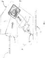
- a pulsed signal 1 is sent from a first LRF (not shown).
- the LRF pulsed signal 1 is received by an object lens O and imaged on the DLP mirror 2 where each pixel(s) represents an angular location in the field of view (FOV) of the receiver.
- the imaged return signal is reflected off the DLP mirror and is modulated by a "shutter" pattern 3 where the reflected light is collected by the condenser 4 to a single element detector, or avalanche photodiode (APD) 5.
- APD avalanche photodiode
- the DLP digitizes the angular location of the signal return to a specific pixel or group of pixels (depending on the resolution) within the DLP array. That specific pixel or group of pixels directly corresponds to the angular location of the return signal or target reflection within the DLP's FOV.
- the pulse data is then processed, as generally indicated by reference numeral 6, to determine the location of the pulsed signal from the first LRF within the FOV of the scanning DLP system. As shown diagrammatically in FIG.
- a covert receiver comprises a DLP mirror 2 applying a shutter pattern 3, a condenser 4, a single element detector 5, and a display 7, which are all encased and enclosed within an exterior housing 8.
- the covert receiver includes a transceiver for communicating the display information to one or more remote displays.
- the integrated display is optional.
- the detected pulsed set 6 shows the first three pulses were detected, the next two were "missing”, i.e., not detected, the following two pulses were detected, the next pulse was "missing”, the following two pulses were detected, the next two pulses were "missing” and the last pulse was detected.
- the method of modulation of the light detected by the DLP mirror will be discussed in more detail below.
- the laser on the LRF emits a set of pulses over a very short period of time. For example, the laser emits a 13 pulse burst at about 5 kHz within a time period of about 2.6 ms.
- the laser pulses are then reflected off a target and the reflected pules are referred to as an "echo.”
- the receiver of the "echo" can processes near-infrared (near-IR) and short-wavelength infrared (SWIR) wavelengths. In some cases, the wavelength used is about 1.5 ⁇ m. In other cases, the receiver is useful over a broader range of wavelengths.
- the receiver detects the first pulse in the laser's pulsed set and then utilizes digital light processing (DLP) to scan for the position of the target's echo.
- DLP mirror is a form of digital micromirror device (DMD).
- DMD is a chip that has several hundred thousand microscopic mirrors provided on its surface and arranged in an array which corresponds to pixels. Each of the individual mirrors can be rotated into either an "on” or “off state. In the "on” state, light from a light source is reflected in the direction of a detector 5 and the pixel appears to be bright. In the "off state, the light is directed elsewhere, e.g., to a light trap for example, making the pixel appear to be dark.
- DLP mirrors are designed for visible and near IR uses.
- the DLP mirror has a transmissive window configured for the working band.
- the DLP mirror can be used with SWIR, MWIR, LWIR, and the like.
- visible light ranges from about 400 nm to about 700 nm and infrared (IR) ranges from about 700 nm to about 1 mm.
- the IR range is further subdivided in to near-IR (about 0.75-1.4 ⁇ m), short-wavelength IR or SWIR (about 1.4-3 ⁇ m), mid-wavelength IR, or MWIR (about 3-8 ⁇ m), long-wavelength IR, or LWIR (8-15 ⁇ m), and far-IR (about 15 ⁇ m -1 mm).
- both the direction and the energy distribution of the laser can be measured.
- the measurement can be done by turning one pixel "on” at a time while all of the other pixels "off.”
- the measurement can be done by using a spatial pattern of a limiting aperture generated by the DLP.
- the limiting aperture could be formed by turning on a group of pixels in circular format.
- the DLP can scan (e.g., turn "on” and "off") by rows and columns, to locate the peak LRF pulse energy (centroid) in DLP pixel space.
- the light measured by the DLP mirror is modulated by a shutter pattern that is synchronized to the pulsed signal from the first LRF.
- This shutter pattern obscures a portion of the field of view by a "divide-by-two" scan; e.g., half of the pixels are turned “on,” and the other half of the pixels are turned “off,” to rapidly identify the location of the target.
- An analogous "divide-by-two" scan is disclosed in another application by Applicant, in U.S. Patent No. 10,234,284 .
- the detected pulse is shown as a dot 9 (representing the target) within the DLP mirror's FOV 10.
- a first pulse in a set is detected without the use of the shutter pattern (e.g., turning some of the micromirrors to an "off position).
- the second pulse coincides with application of the shutter pattern to the bottom half of the DLP mirror's FOV (e.g., Pattern 1 in FIG. 2 ).
- the third pulse coincides with application of the shutter pattern to one side of the DLP mirror's FOV (e.g., Pattern 2 in FIG. 2 ).
- the fourth pulse coincides with Pattern 3 in FIG. 3 , and so on.
- the system of the present disclosure is small, compact, lightweight and low cost as there is no need for a SWIR, or similar camera, to detect and process the pulses sent from a LRF.
- the system as described herein makes both covert pointing and covert communication possible using a LRF operated by one user and a receiver operated by an independent and distinct second user.
- the wavelengths chosen can be from a group that is not often used in the field so as to provide covert communication between the first and the second user.
- the pulse repetition interval (PRI) of the laser can be modified "on the fly" to allow communication between like users on a battle field.
- a pulsed set with a particular pause between specific pulses might indicate a first message, where another different sequence may indicate a second message, and so on.
- a preprogrammed library of messages would be unique to a set of users so that even if the laser signals were to be intercepted the significance would not be apparent.
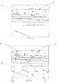
- FIG. 3 a diagrammatic illustration shows a scene being viewed by a receiver, according to the principles of the present disclosure, with multiple targets located within the scene.
- a first target 11 has been marked as a "friend” by an LRF according to the principles of the present disclosure while a second target 11' has been marked as a "foe.”
- the system of the present disclosure provides at least two users, remote from each other, with the ability to communicate covertly about a scene, e.g., to indicate the "friend" from the "foe.”
- the communication might include target identifying information, instructions, or simple messages relating to the quality of the signals or the status of the user.
- the a user is looking at a section of terrain through a viewer and overlaid on that view is a light or other indication that identifies the location of a target of interest.
- the color of the light might correspond to target information such as "friend” or “foe.”
- the color might represent commands such as "engage” or "hold.”
- a particular symbology unique to a particular group of users might be used to convey information sent via the modulated laser pulses.
- FIG. 4 a diagrammatic illustration of a scene being tagged by a LRF 16 and read by a receiver 17, according to the principles of present disclosure, with multiple tagged targets located within the scene is shown. That is, the first device 16 sends a first pulsed laser set 12 to a first target 11 and a second pulsed laser set 13 to a second target 11'.
- a second device 17 receives a first target's location information and/or a message 14, from the first target 11, and a second target's location information and/or a message 15, from the second target 11'.
- the first device is a simple LRF capable of modifying the pulse repetition interval (PRI) to code a target as "friend” or "foe,” or send other predetermined messages.
- the second device is a receiver for receiving modulated LRF signals.
- a first laser, e.g., LRF, 16 can be pointed at a target and a second receiver (e.g., a second operator in a different location operating receiver 17) can detect the pulses sent by the first laser.
- a second receiver e.g., a second operator in a different location operating receiver 17
- a message can be received by the second operator.
- a message of "got it" might be returned to the source of the original laser point on target.
- Another example might be a message of "bad signal,” or "engage,” or the like.
- a message of 'friend" or "foe” might be used to mark a target so that other operators can assess a scene.
- a series of predetermined modulated waveforms could be used for covert communication between two or more users that are not in proximity or even within line of sight of each other, but rather are communicating with one another via the echo off a target.
- the use of the shutter patterns on the DLP FOV, as described herein, can determine accurately where a target of interest is located with respect to each user and the type of target, e.g., "friend,” "foe,” etc.
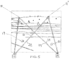
- FIG. 5 a diagrammatic illustration of a scene where communication is occurring between a first LRF/receiver and a second LRF/receiver, according to the present disclosure, with multiple tagged targets located within the scene, is shown. More particularly, the LRF/receiver devices 18 and 19 are located spaced apart from each other and are sending and receiving communications through modulated laser pulses as described herein. A first target 11 has been marked as "friend” and a second target has been marked as "foe” as in the previous example. The first device (LRF/receiver) 18 has tagged 11 and 11' with signals 20 and 21 and receives responses from the second device 19 (LRF/receiver) off the same targets via signals 19 and 22. Likewise, the second device 19 receives target location and other information from the first device 18 via signals 23 and 25 and sends responses, or other messages to the first device 18 via signals 26 and 24.
- LRF/receiver devices 18 and 19 are located spaced apart from each other and are sending and receiving communications through modul
- one or both of the devices comprise a receiver for receiving signals from other LRF devices that have tagged a target with information or that are privy to the predetermined messages/symbology used to communicate a variety of information.
- one or both of the devices comprises a LRF capable of modifying the pulse repetition interval (PRI) to code a target as "friend” or "foe,” or send other predetermined messages.
- PRI pulse repetition interval
- FIG. 6 a diagrammatic view of another embodiment of the LRF/receiver of the system of the present disclosure is shown. More particularly, a pulsed signal 1' is sent from a first LRF (not shown). The pulsed signal 1' is received by an object lens and imaged on the DLP mirrors 2' where each pixel(s) represents an angular location in the field of view (FOV) of the receiver. The imaged return signal is reflected off the DLP mirror and is modulated by a shutter pattern 3' where the reflected light is collected by the condenser 4' to a single element detector, or avalanche photodiode (APD) 5'.
- APD avalanche photodiode
- the DLP digitizes the angular location of the signal return to a specific pixel or group of pixels (depending on the resolution) within the DLP mirror array. That specific pixel or group of pixels directly corresponds to the angular location of the return signal or target reflection within the DLP's FOV.
- the pulse data is then processed, as generally indicated by reference numeral 6', to determine the location of the pulsed signal from the first LRF within the FOV of the scanning DLP mirror.
- an LRF/receiver comprises a DLP mirror 2' applying a shutter pattern 3', a condenser 4', a single element detector 5', and a display 7', which are all encased and enclosed within an exterior housing 8'.
- a LRF 28 is present and is used to return/send modulated pulsed laser signals to other receivers as described herein.
- a transceiver 30 is also present and is used to communicate with other operators both on and off the field via wireless technology.
- the portion of terrain with the overlain target location and other information may be transmitted to others located remotely. In other cases, bearing, range, and other information may be transmitted to other users.
- the laser beam of a LRF has some amount of divergence. In some cases, that divergence may be about 6° or so. In some situations, according to the principles of the present disclosure, the LRF may be located on a weapon or hand pointed by an operator. In some cases, the laser in the LRF is a 100 ⁇ J laser, 1.5 ⁇ m (eye safety) 5 KHz laser, providing a 13 pulse burst mode during the LRF mode while providing a continuous stream of pulse in the communication mode of varying PRI codes.
- a 6 x 6 degree window is assumed for the DLP array.
- 2 12 yields a 4,096 reduction or 0.09 degree bins or +/- 0.045 degree accuracy.
- Preprogram binary mirror patterns are implemented after confirmation of the first pulse return with the mirror completely in the "on" position. As the second pulse leaves the system the new mirror pattern is already initiated to spatially modulate the next pulse return. This is repeated until all pulses are processed. With a laser rate of about 1 kHz, a scan can be completed in about 0.012 seconds. In certain embodiments, all returns can be scanned simultaneously within the 0.012 seconds using temporal and spatial filtering.
- the DLP is a 1/3 WVGA (wide video graphics array) with a 7.6 ⁇ m pitch, 608 x 684 array, windowed to 320 x 256.
- the DLP has a scan rate over 4 kHz and uses about 0.1 watt of power.
- the system can determine range, bearing, and target coordinates using self-location. Bearing and range changes can be focused on as GPS indicates movement in the target. A revisit rate of about every second can be used with little to no power consumption.
- SNR signal-to-noise ratio
- the system is low cost, in part, because there is no need for a SWIR, or similar, camera.
- the system can be used for covertly targeting and for limited covert communications.
- the system is lightweight and inexpensive and can be incorporated into existing systems, including weapons, hand held targeting systems, and night vision goggles where the results are overlaid onto the display. In other instances, the target location information may be transmitted to an operator remote from the receiver.
Landscapes
- Engineering & Computer Science (AREA)
- Physics & Mathematics (AREA)
- Computer Networks & Wireless Communication (AREA)
- General Physics & Mathematics (AREA)
- Radar, Positioning & Navigation (AREA)
- Remote Sensing (AREA)
- Electromagnetism (AREA)
- Optics & Photonics (AREA)
- Optical Radar Systems And Details Thereof (AREA)
Claims (10)
- System zum verdeckten Zielen, umfassendeine digitale Lichtverarbeitungs(digital light processing - DLP)-Spiegelanordnung (2) zum Umlenken einer Reihe von Laserimpulsen, die von einem Ziel von Interesse reflektiert wurden; undeinen Prozessor zum Bestimmen, über einen Einzelelementdetektor (5), ob ein Impuls in der Reihe von Laserimpulsen auf jeder der Reihen von modulierten Sichtfeldern der DLP-Spiegelanordnung (2) erfasst wurde, um den Standort des Ziels von Interesse zu bestimmen; undeine Anzeige (7) zum Präsentieren, einem Bediener, von Standortinformationen für das Ziel von Interesse, DADURCH GEKENNZEICHNET, DASS die DLP-Spiegelanordnung (2) Blendenmuster (3) anwendet, um eine Reihe von modulierten Sichtfeldern der DLP-Spiegelanordnung (2) zu erstellen, unter Verwendung eines "Durch-Zwei-Teilen"-Schemas.
- System zum verdeckten Zielen nach Anspruch 1, wobei die Anzeige (7) von dem Prozessor entfernt ist.
- System zum verdeckten Zielen nach Anspruch 1, ferner umfassend eine gepulste Laserquelle, die einen Modulator zum Erzeugen der Reihe von Laserimpulsen aufweist.
- System zum verdeckten Zielen nach Anspruch 1, ferner umfassend einen Transceiver zum drahtlosen Kommunizieren.
- System zum verdeckten Zielen nach Anspruch 4, wobei der Transceiver Standortinformationen für das Ziel von Interesse überträgt.
- Verfahren zum verdeckten Kommunizieren, umfassendein Bereitstellen, einem ersten Bediener, einer ersten gepulsten Laserquelle, die einen Modulator zum Erzeugen einer ersten Reihe von Laserimpulsen aufweist;ein Bereitstellen, einem zweiten Bediener, eines Empfängers , umfassend,eine DLP-Spiegelanordnung (2) zum Umlenken der ersten Reihe von Laserimpulsen, die von einem Ziel von Interesse reflektiert wurden; undeinen Prozessor zum Bestimmen, über einen Einzelelementdetektor (5), ob ein Impuls in der Reihe von ersten Laserimpulsen auf jeder der Reihen von modulierten Sichtfeldern der DLP-Spiegelanordnung (2) erfasst wurde;Bestimmen, mit dem Prozessor, des Standortes des Ziels von Interesse durch Vergleichen von Impulsen, die in einem ersten modulierten Sichtfeld erfasst wurden, mit Impulsen, die nicht in einem anderen modulierten Sichtfeld erfasst wurden;Präsentieren, einem zweiten Bediener, auf einer Anzeige (7), von Standortinformationen des Ziels von Interesse; undKennzeichnen des Ziels von Interesse durch den ersten Bediener durch Senden einer ersten modulierten Reihe von Laserimpulsen an das Ziel, DADURCH GEKENNZEICHNET, DASS die DLP-Spiegelanordnung (2) Blendenmuster (3) anwendet, um eine Reihe von modulierten Sichtfeldern der DLP-Spiegelanordnung (2) zu erstellen, unter Verwendung eines "Durch-Zwei-Teilen"-Schemas.
- Verfahren zum verdeckten Kommunizieren nach Anspruch 6, ferner umfassend das Bereitstellen, dem zweiten Bediener, einer zweiten gepulsten Laserquelle, die einen Modulator zum Erzeugen einer zweiten Reihe von Laserimpulsen aufweist.
- Verfahren zum verdeckten Kommunizieren nach Anspruch 7, ferner umfassend das Senden einer zweiten modulierten Reihe von Laserimpulsen durch den zweiten Bediener an den ersten Bediener.
- Verfahren zum verdeckten Kommunizieren nach Anspruch 6, wobei die Blendenmuster (3) das Sichtfeld der DLP-Spiegelanordnung unter Verwendung eines "Durch-Zwei-Teilen"-Schemas modulieren.
- Verfahren zum verdeckten Kommunizieren nach Anspruch 6, wobei die modulierten Reihen von Laserimpulsen durch Modifizieren des Impulswiederholungsintervalls (PRI - pulse repetition interval) einer Laserquelle auf eine vorbestimmte Weise erstellt werden.
Applications Claiming Priority (2)
| Application Number | Priority Date | Filing Date | Title |
|---|---|---|---|
| US15/344,849 US10267900B2 (en) | 2016-11-07 | 2016-11-07 | System and method for covert pointer/communications and laser range finder |
| PCT/US2017/059250 WO2018085255A1 (en) | 2016-11-07 | 2017-10-31 | System and method for covert pointer/communications and laser range finder |
Publications (3)
| Publication Number | Publication Date |
|---|---|
| EP3535604A1 EP3535604A1 (de) | 2019-09-11 |
| EP3535604A4 EP3535604A4 (de) | 2020-08-12 |
| EP3535604B1 true EP3535604B1 (de) | 2022-09-21 |
Family
ID=62064444
Family Applications (1)
| Application Number | Title | Priority Date | Filing Date |
|---|---|---|---|
| EP17868155.7A Active EP3535604B1 (de) | 2016-11-07 | 2017-10-31 | System und verfahren für verborgene zeiger/kommunikation und laserentfernungsmesser |
Country Status (3)
| Country | Link |
|---|---|
| US (1) | US10267900B2 (de) |
| EP (1) | EP3535604B1 (de) |
| WO (1) | WO2018085255A1 (de) |
Families Citing this family (3)
| Publication number | Priority date | Publication date | Assignee | Title |
|---|---|---|---|---|
| US10267900B2 (en) | 2016-11-07 | 2019-04-23 | Bae Systems Information And Electronic Systems Integration Inc. | System and method for covert pointer/communications and laser range finder |
| JP7004632B2 (ja) * | 2018-10-05 | 2022-01-21 | 京セラ株式会社 | 電磁波検出装置 |
| FI128399B (en) * | 2019-04-23 | 2020-04-30 | Teknologian Tutkimuskeskus Vtt Oy | System for providing sneaky vision |
Family Cites Families (18)
| Publication number | Priority date | Publication date | Assignee | Title |
|---|---|---|---|---|
| US5555662A (en) | 1993-06-08 | 1996-09-17 | Teetzel; James W. | Laser range finding apparatus |
| US5583688A (en) | 1993-12-21 | 1996-12-10 | Texas Instruments Incorporated | Multi-level digital micromirror device |
| SE522552C2 (sv) | 2002-10-18 | 2004-02-17 | Peter Stevrin | Mobiltelefon med integrerad eller ansluten laseravståndsmätare |
| US20040213463A1 (en) * | 2003-04-22 | 2004-10-28 | Morrison Rick Lee | Multiplexed, spatially encoded illumination system for determining imaging and range estimation |
| US6839127B1 (en) | 2003-09-15 | 2005-01-04 | Deere & Company | Optical range finder having a micro-mirror array |
| US7064810B2 (en) | 2003-09-15 | 2006-06-20 | Deere & Company | Optical range finder with directed attention |
| US8210044B1 (en) | 2007-10-12 | 2012-07-03 | California Institute Of Technology | Covert laser remote sensing and vibrometry |
| DE102008021465A1 (de) * | 2008-04-29 | 2009-11-05 | Fraunhofer-Gesellschaft zur Förderung der angewandten Forschung e.V. | Entfernungsmesssystem |
| US8648914B1 (en) * | 2009-12-31 | 2014-02-11 | Teledyne Scientific & Imaging, Llc | Laser communication system for spatial referencing |
| US8982363B2 (en) * | 2011-10-07 | 2015-03-17 | Massachusetts Institute Of Technology | Method and apparatus to determine depth information for a scene of interest |
| US9528819B2 (en) | 2011-10-14 | 2016-12-27 | Iee International Electronics & Engineering S.A. | Spatially selective detection using a dynamic mask in an image plane |
| CN102520412A (zh) | 2011-11-18 | 2012-06-27 | 西安交通大学 | 基于微机械mems 二维扫描镜阵列的激光主动探测装置 |
| JP6315268B2 (ja) | 2014-07-02 | 2018-04-25 | 船井電機株式会社 | レーザレンジファインダ |
| JP6660931B2 (ja) | 2014-07-08 | 2020-03-11 | ビーエーエスエフ ソシエタス・ヨーロピアBasf Se | 少なくとも1つの物体の位置を決定するための検出器 |
| US9823350B2 (en) | 2014-07-31 | 2017-11-21 | Raytheon Company | Linear mode computational sensing LADAR |
| KR102497704B1 (ko) | 2014-12-09 | 2023-02-09 | 바스프 에스이 | 광 검출기 |
| US10234284B2 (en) | 2016-05-13 | 2019-03-19 | Bae Systems Information And Electronic Systems Integration Inc. | Multifunctional rangefinder with at least two modes of operation |
| US10267900B2 (en) | 2016-11-07 | 2019-04-23 | Bae Systems Information And Electronic Systems Integration Inc. | System and method for covert pointer/communications and laser range finder |
-
2016
- 2016-11-07 US US15/344,849 patent/US10267900B2/en active Active
-
2017
- 2017-10-31 WO PCT/US2017/059250 patent/WO2018085255A1/en not_active Ceased
- 2017-10-31 EP EP17868155.7A patent/EP3535604B1/de active Active
Also Published As
| Publication number | Publication date |
|---|---|
| WO2018085255A1 (en) | 2018-05-11 |
| EP3535604A4 (de) | 2020-08-12 |
| US20180128906A1 (en) | 2018-05-10 |
| US10267900B2 (en) | 2019-04-23 |
| EP3535604A1 (de) | 2019-09-11 |
Similar Documents
| Publication | Publication Date | Title |
|---|---|---|
| US9897688B2 (en) | Laser detection and image fusion system and method | |
| US8994819B2 (en) | Integrated optical detection system | |
| EP3195042B1 (de) | Rechnergestützter abtastender linearmodus-ladar | |
| EP2453253B1 (de) | Multidirektionales aktives Sensorsystem und Verfahren zur Messung elektromagnetischer Strahlung | |
| US9513367B2 (en) | Image gated camera for detecting objects in a marine environment | |
| JP7627231B2 (ja) | 無人飛行機の飛行制御システム及び地形計測システム | |
| US10408574B2 (en) | Compact laser and geolocating targeting system | |
| US20030067537A1 (en) | System and method for three-dimensional data acquisition | |
| US10901070B2 (en) | Coordinate measuring device having automatic target object recognition | |
| CA2987462C (en) | Observation device having an eye-controlled laser rangefinder | |
| EP1515162B1 (de) | Gerät zum entdecken von optischen und optoelektronischen objekten | |
| US8648914B1 (en) | Laser communication system for spatial referencing | |
| EP3535604B1 (de) | System und verfahren für verborgene zeiger/kommunikation und laserentfernungsmesser | |
| US8731240B1 (en) | System and method for optics detection | |
| US20210389424A1 (en) | Lidar device | |
| WO2017055549A1 (fr) | Procédé et équipement embarqué d'aide au roulage et à l'anticollision de véhicule, en particulier d'aéronef | |
| US10031229B1 (en) | Object designator system and method | |
| US20240361463A1 (en) | Hand-held observation device and method for obtaining a 3d point cloud | |
| US20150092179A1 (en) | Light ranging with moving sensor array | |
| US6301371B1 (en) | Object identification system applications | |
| RU2540154C2 (ru) | Устройство обнаружения оптических и оптико-электронных приборов | |
| WO2024013142A1 (en) | Image capture device with wavelength separation device | |
| CN117630876A (zh) | 具有tof传感器的测量设备 | |
| WO1999018423A1 (en) | Object identification system applications | |
| JPS61100682A (ja) | レ−ザ測距装置 |
Legal Events
| Date | Code | Title | Description |
|---|---|---|---|
| STAA | Information on the status of an ep patent application or granted ep patent |
Free format text: STATUS: THE INTERNATIONAL PUBLICATION HAS BEEN MADE |
|
| PUAI | Public reference made under article 153(3) epc to a published international application that has entered the european phase |
Free format text: ORIGINAL CODE: 0009012 |
|
| STAA | Information on the status of an ep patent application or granted ep patent |
Free format text: STATUS: REQUEST FOR EXAMINATION WAS MADE |
|
| 17P | Request for examination filed |
Effective date: 20190508 |
|
| AK | Designated contracting states |
Kind code of ref document: A1 Designated state(s): AL AT BE BG CH CY CZ DE DK EE ES FI FR GB GR HR HU IE IS IT LI LT LU LV MC MK MT NL NO PL PT RO RS SE SI SK SM TR |
|
| AX | Request for extension of the european patent |
Extension state: BA ME |
|
| DAV | Request for validation of the european patent (deleted) | ||
| DAX | Request for extension of the european patent (deleted) | ||
| REG | Reference to a national code |
Ref country code: DE Ref legal event code: R079 Ref document number: 602017062045 Country of ref document: DE Free format text: PREVIOUS MAIN CLASS: G01S0007486000 Ipc: G01S0007486100 |
|
| A4 | Supplementary search report drawn up and despatched |
Effective date: 20200713 |
|
| RIC1 | Information provided on ipc code assigned before grant |
Ipc: G01S 7/48 20060101ALI20200707BHEP Ipc: G01S 7/481 20060101ALI20200707BHEP Ipc: G02B 26/08 20060101ALI20200707BHEP Ipc: G01S 7/484 20060101ALI20200707BHEP Ipc: G01S 7/4861 20200101AFI20200707BHEP Ipc: G01S 7/51 20060101ALI20200707BHEP Ipc: G01S 17/10 20200101ALI20200707BHEP Ipc: F41G 3/16 20060101ALI20200707BHEP Ipc: F41G 3/14 20060101ALI20200707BHEP Ipc: G01S 17/66 20060101ALI20200707BHEP |
|
| GRAP | Despatch of communication of intention to grant a patent |
Free format text: ORIGINAL CODE: EPIDOSNIGR1 |
|
| STAA | Information on the status of an ep patent application or granted ep patent |
Free format text: STATUS: GRANT OF PATENT IS INTENDED |
|
| INTG | Intention to grant announced |
Effective date: 20220422 |
|
| GRAS | Grant fee paid |
Free format text: ORIGINAL CODE: EPIDOSNIGR3 |
|
| GRAA | (expected) grant |
Free format text: ORIGINAL CODE: 0009210 |
|
| STAA | Information on the status of an ep patent application or granted ep patent |
Free format text: STATUS: THE PATENT HAS BEEN GRANTED |
|
| AK | Designated contracting states |
Kind code of ref document: B1 Designated state(s): AL AT BE BG CH CY CZ DE DK EE ES FI FR GB GR HR HU IE IS IT LI LT LU LV MC MK MT NL NO PL PT RO RS SE SI SK SM TR |
|
| REG | Reference to a national code |
Ref country code: GB Ref legal event code: FG4D |
|
| REG | Reference to a national code |
Ref country code: CH Ref legal event code: EP |
|
| REG | Reference to a national code |
Ref country code: DE Ref legal event code: R096 Ref document number: 602017062045 Country of ref document: DE |
|
| REG | Reference to a national code |
Ref country code: IE Ref legal event code: FG4D |
|
| REG | Reference to a national code |
Ref country code: AT Ref legal event code: REF Ref document number: 1520207 Country of ref document: AT Kind code of ref document: T Effective date: 20221015 |
|
| REG | Reference to a national code |
Ref country code: LT Ref legal event code: MG9D |
|
| REG | Reference to a national code |
Ref country code: NL Ref legal event code: MP Effective date: 20220921 |
|
| PG25 | Lapsed in a contracting state [announced via postgrant information from national office to epo] |
Ref country code: SE Free format text: LAPSE BECAUSE OF FAILURE TO SUBMIT A TRANSLATION OF THE DESCRIPTION OR TO PAY THE FEE WITHIN THE PRESCRIBED TIME-LIMIT Effective date: 20220921 Ref country code: RS Free format text: LAPSE BECAUSE OF FAILURE TO SUBMIT A TRANSLATION OF THE DESCRIPTION OR TO PAY THE FEE WITHIN THE PRESCRIBED TIME-LIMIT Effective date: 20220921 Ref country code: NO Free format text: LAPSE BECAUSE OF FAILURE TO SUBMIT A TRANSLATION OF THE DESCRIPTION OR TO PAY THE FEE WITHIN THE PRESCRIBED TIME-LIMIT Effective date: 20221221 Ref country code: LV Free format text: LAPSE BECAUSE OF FAILURE TO SUBMIT A TRANSLATION OF THE DESCRIPTION OR TO PAY THE FEE WITHIN THE PRESCRIBED TIME-LIMIT Effective date: 20220921 Ref country code: LT Free format text: LAPSE BECAUSE OF FAILURE TO SUBMIT A TRANSLATION OF THE DESCRIPTION OR TO PAY THE FEE WITHIN THE PRESCRIBED TIME-LIMIT Effective date: 20220921 Ref country code: FI Free format text: LAPSE BECAUSE OF FAILURE TO SUBMIT A TRANSLATION OF THE DESCRIPTION OR TO PAY THE FEE WITHIN THE PRESCRIBED TIME-LIMIT Effective date: 20220921 |
|
| REG | Reference to a national code |
Ref country code: AT Ref legal event code: MK05 Ref document number: 1520207 Country of ref document: AT Kind code of ref document: T Effective date: 20220921 |
|
| PG25 | Lapsed in a contracting state [announced via postgrant information from national office to epo] |
Ref country code: HR Free format text: LAPSE BECAUSE OF FAILURE TO SUBMIT A TRANSLATION OF THE DESCRIPTION OR TO PAY THE FEE WITHIN THE PRESCRIBED TIME-LIMIT Effective date: 20220921 Ref country code: GR Free format text: LAPSE BECAUSE OF FAILURE TO SUBMIT A TRANSLATION OF THE DESCRIPTION OR TO PAY THE FEE WITHIN THE PRESCRIBED TIME-LIMIT Effective date: 20221222 |
|
| PG25 | Lapsed in a contracting state [announced via postgrant information from national office to epo] |
Ref country code: SM Free format text: LAPSE BECAUSE OF FAILURE TO SUBMIT A TRANSLATION OF THE DESCRIPTION OR TO PAY THE FEE WITHIN THE PRESCRIBED TIME-LIMIT Effective date: 20220921 Ref country code: RO Free format text: LAPSE BECAUSE OF FAILURE TO SUBMIT A TRANSLATION OF THE DESCRIPTION OR TO PAY THE FEE WITHIN THE PRESCRIBED TIME-LIMIT Effective date: 20220921 Ref country code: PT Free format text: LAPSE BECAUSE OF FAILURE TO SUBMIT A TRANSLATION OF THE DESCRIPTION OR TO PAY THE FEE WITHIN THE PRESCRIBED TIME-LIMIT Effective date: 20230123 Ref country code: ES Free format text: LAPSE BECAUSE OF FAILURE TO SUBMIT A TRANSLATION OF THE DESCRIPTION OR TO PAY THE FEE WITHIN THE PRESCRIBED TIME-LIMIT Effective date: 20220921 Ref country code: CZ Free format text: LAPSE BECAUSE OF FAILURE TO SUBMIT A TRANSLATION OF THE DESCRIPTION OR TO PAY THE FEE WITHIN THE PRESCRIBED TIME-LIMIT Effective date: 20220921 Ref country code: AT Free format text: LAPSE BECAUSE OF FAILURE TO SUBMIT A TRANSLATION OF THE DESCRIPTION OR TO PAY THE FEE WITHIN THE PRESCRIBED TIME-LIMIT Effective date: 20220921 |
|
| PG25 | Lapsed in a contracting state [announced via postgrant information from national office to epo] |
Ref country code: SK Free format text: LAPSE BECAUSE OF FAILURE TO SUBMIT A TRANSLATION OF THE DESCRIPTION OR TO PAY THE FEE WITHIN THE PRESCRIBED TIME-LIMIT Effective date: 20220921 Ref country code: PL Free format text: LAPSE BECAUSE OF FAILURE TO SUBMIT A TRANSLATION OF THE DESCRIPTION OR TO PAY THE FEE WITHIN THE PRESCRIBED TIME-LIMIT Effective date: 20220921 Ref country code: IS Free format text: LAPSE BECAUSE OF FAILURE TO SUBMIT A TRANSLATION OF THE DESCRIPTION OR TO PAY THE FEE WITHIN THE PRESCRIBED TIME-LIMIT Effective date: 20230121 Ref country code: EE Free format text: LAPSE BECAUSE OF FAILURE TO SUBMIT A TRANSLATION OF THE DESCRIPTION OR TO PAY THE FEE WITHIN THE PRESCRIBED TIME-LIMIT Effective date: 20220921 |
|
| REG | Reference to a national code |
Ref country code: CH Ref legal event code: PL |
|
| REG | Reference to a national code |
Ref country code: DE Ref legal event code: R097 Ref document number: 602017062045 Country of ref document: DE |
|
| REG | Reference to a national code |
Ref country code: BE Ref legal event code: MM Effective date: 20221031 |
|
| PG25 | Lapsed in a contracting state [announced via postgrant information from national office to epo] |
Ref country code: NL Free format text: LAPSE BECAUSE OF FAILURE TO SUBMIT A TRANSLATION OF THE DESCRIPTION OR TO PAY THE FEE WITHIN THE PRESCRIBED TIME-LIMIT Effective date: 20220921 Ref country code: MC Free format text: LAPSE BECAUSE OF FAILURE TO SUBMIT A TRANSLATION OF THE DESCRIPTION OR TO PAY THE FEE WITHIN THE PRESCRIBED TIME-LIMIT Effective date: 20220921 Ref country code: LU Free format text: LAPSE BECAUSE OF NON-PAYMENT OF DUE FEES Effective date: 20221031 Ref country code: AL Free format text: LAPSE BECAUSE OF FAILURE TO SUBMIT A TRANSLATION OF THE DESCRIPTION OR TO PAY THE FEE WITHIN THE PRESCRIBED TIME-LIMIT Effective date: 20220921 |
|
| PLBE | No opposition filed within time limit |
Free format text: ORIGINAL CODE: 0009261 |
|
| STAA | Information on the status of an ep patent application or granted ep patent |
Free format text: STATUS: NO OPPOSITION FILED WITHIN TIME LIMIT |
|
| PG25 | Lapsed in a contracting state [announced via postgrant information from national office to epo] |
Ref country code: LI Free format text: LAPSE BECAUSE OF NON-PAYMENT OF DUE FEES Effective date: 20221031 Ref country code: DK Free format text: LAPSE BECAUSE OF FAILURE TO SUBMIT A TRANSLATION OF THE DESCRIPTION OR TO PAY THE FEE WITHIN THE PRESCRIBED TIME-LIMIT Effective date: 20220921 Ref country code: CH Free format text: LAPSE BECAUSE OF NON-PAYMENT OF DUE FEES Effective date: 20221031 |
|
| 26N | No opposition filed |
Effective date: 20230622 |
|
| PG25 | Lapsed in a contracting state [announced via postgrant information from national office to epo] |
Ref country code: SI Free format text: LAPSE BECAUSE OF FAILURE TO SUBMIT A TRANSLATION OF THE DESCRIPTION OR TO PAY THE FEE WITHIN THE PRESCRIBED TIME-LIMIT Effective date: 20220921 |
|
| PG25 | Lapsed in a contracting state [announced via postgrant information from national office to epo] |
Ref country code: BE Free format text: LAPSE BECAUSE OF NON-PAYMENT OF DUE FEES Effective date: 20221031 |
|
| PG25 | Lapsed in a contracting state [announced via postgrant information from national office to epo] |
Ref country code: IE Free format text: LAPSE BECAUSE OF NON-PAYMENT OF DUE FEES Effective date: 20221031 |
|
| PG25 | Lapsed in a contracting state [announced via postgrant information from national office to epo] |
Ref country code: HU Free format text: LAPSE BECAUSE OF FAILURE TO SUBMIT A TRANSLATION OF THE DESCRIPTION OR TO PAY THE FEE WITHIN THE PRESCRIBED TIME-LIMIT; INVALID AB INITIO Effective date: 20171031 |
|
| PG25 | Lapsed in a contracting state [announced via postgrant information from national office to epo] |
Ref country code: CY Free format text: LAPSE BECAUSE OF FAILURE TO SUBMIT A TRANSLATION OF THE DESCRIPTION OR TO PAY THE FEE WITHIN THE PRESCRIBED TIME-LIMIT Effective date: 20220921 |
|
| PG25 | Lapsed in a contracting state [announced via postgrant information from national office to epo] |
Ref country code: MK Free format text: LAPSE BECAUSE OF FAILURE TO SUBMIT A TRANSLATION OF THE DESCRIPTION OR TO PAY THE FEE WITHIN THE PRESCRIBED TIME-LIMIT Effective date: 20220921 |
|
| PG25 | Lapsed in a contracting state [announced via postgrant information from national office to epo] |
Ref country code: BG Free format text: LAPSE BECAUSE OF FAILURE TO SUBMIT A TRANSLATION OF THE DESCRIPTION OR TO PAY THE FEE WITHIN THE PRESCRIBED TIME-LIMIT Effective date: 20220921 |
|
| PG25 | Lapsed in a contracting state [announced via postgrant information from national office to epo] |
Ref country code: MT Free format text: LAPSE BECAUSE OF FAILURE TO SUBMIT A TRANSLATION OF THE DESCRIPTION OR TO PAY THE FEE WITHIN THE PRESCRIBED TIME-LIMIT Effective date: 20220921 |
|
| PGFP | Annual fee paid to national office [announced via postgrant information from national office to epo] |
Ref country code: GB Payment date: 20241127 Year of fee payment: 8 |
|
| PGFP | Annual fee paid to national office [announced via postgrant information from national office to epo] |
Ref country code: IT Payment date: 20241122 Year of fee payment: 8 |
|
| PGFP | Annual fee paid to national office [announced via postgrant information from national office to epo] |
Ref country code: DE Payment date: 20250430 Year of fee payment: 8 |
|
| PGFP | Annual fee paid to national office [announced via postgrant information from national office to epo] |
Ref country code: FR Payment date: 20250429 Year of fee payment: 8 |
|
| PG25 | Lapsed in a contracting state [announced via postgrant information from national office to epo] |
Ref country code: TR Free format text: LAPSE BECAUSE OF FAILURE TO SUBMIT A TRANSLATION OF THE DESCRIPTION OR TO PAY THE FEE WITHIN THE PRESCRIBED TIME-LIMIT Effective date: 20220921 |