EP3535563B1 - Method and apparatus for measuring a concentration of a gas - Google Patents
Method and apparatus for measuring a concentration of a gas Download PDFInfo
- Publication number
- EP3535563B1 EP3535563B1 EP17798154.5A EP17798154A EP3535563B1 EP 3535563 B1 EP3535563 B1 EP 3535563B1 EP 17798154 A EP17798154 A EP 17798154A EP 3535563 B1 EP3535563 B1 EP 3535563B1
- Authority
- EP
- European Patent Office
- Prior art keywords
- container
- gas
- radiation
- concentration
- positioning
- Prior art date
- Legal status (The legal status is an assumption and is not a legal conclusion. Google has not performed a legal analysis and makes no representation as to the accuracy of the status listed.)
- Active
Links
Images


Classifications
-
- B—PERFORMING OPERATIONS; TRANSPORTING
- B65—CONVEYING; PACKING; STORING; HANDLING THIN OR FILAMENTARY MATERIAL
- B65B—MACHINES, APPARATUS OR DEVICES FOR, OR METHODS OF, PACKAGING ARTICLES OR MATERIALS; UNPACKING
- B65B31/00—Packaging articles or materials under special atmospheric or gaseous conditions; Adding propellants to aerosol containers
-
- B—PERFORMING OPERATIONS; TRANSPORTING
- B65—CONVEYING; PACKING; STORING; HANDLING THIN OR FILAMENTARY MATERIAL
- B65B—MACHINES, APPARATUS OR DEVICES FOR, OR METHODS OF, PACKAGING ARTICLES OR MATERIALS; UNPACKING
- B65B57/00—Automatic control, checking, warning, or safety devices
-
- G—PHYSICS
- G01—MEASURING; TESTING
- G01N—INVESTIGATING OR ANALYSING MATERIALS BY DETERMINING THEIR CHEMICAL OR PHYSICAL PROPERTIES
- G01N21/00—Investigating or analysing materials by the use of optical means, i.e. using sub-millimetre waves, infrared, visible or ultraviolet light
- G01N21/01—Arrangements or apparatus for facilitating the optical investigation
- G01N21/03—Cuvette constructions
- G01N21/0303—Optical path conditioning in cuvettes, e.g. windows; adapted optical elements or systems; path modifying or adjustment
-
- G—PHYSICS
- G01—MEASURING; TESTING
- G01N—INVESTIGATING OR ANALYSING MATERIALS BY DETERMINING THEIR CHEMICAL OR PHYSICAL PROPERTIES
- G01N21/00—Investigating or analysing materials by the use of optical means, i.e. using sub-millimetre waves, infrared, visible or ultraviolet light
- G01N21/01—Arrangements or apparatus for facilitating the optical investigation
- G01N21/03—Cuvette constructions
- G01N21/031—Multipass arrangements
-
- G—PHYSICS
- G01—MEASURING; TESTING
- G01N—INVESTIGATING OR ANALYSING MATERIALS BY DETERMINING THEIR CHEMICAL OR PHYSICAL PROPERTIES
- G01N21/00—Investigating or analysing materials by the use of optical means, i.e. using sub-millimetre waves, infrared, visible or ultraviolet light
- G01N21/17—Systems in which incident light is modified in accordance with the properties of the material investigated
- G01N21/1717—Systems in which incident light is modified in accordance with the properties of the material investigated with a modulation of one or more physical properties of the sample during the optical investigation, e.g. electro-reflectance
-
- G—PHYSICS
- G01—MEASURING; TESTING
- G01N—INVESTIGATING OR ANALYSING MATERIALS BY DETERMINING THEIR CHEMICAL OR PHYSICAL PROPERTIES
- G01N21/00—Investigating or analysing materials by the use of optical means, i.e. using sub-millimetre waves, infrared, visible or ultraviolet light
- G01N21/17—Systems in which incident light is modified in accordance with the properties of the material investigated
- G01N21/25—Colour; Spectral properties, i.e. comparison of effect of material on the light at two or more different wavelengths or wavelength bands
- G01N21/31—Investigating relative effect of material at wavelengths characteristic of specific elements or molecules, e.g. atomic absorption spectrometry
- G01N21/35—Investigating relative effect of material at wavelengths characteristic of specific elements or molecules, e.g. atomic absorption spectrometry using infrared light
- G01N21/3504—Investigating relative effect of material at wavelengths characteristic of specific elements or molecules, e.g. atomic absorption spectrometry using infrared light for analysing gases, e.g. multi-gas analysis
-
- G—PHYSICS
- G01—MEASURING; TESTING
- G01N—INVESTIGATING OR ANALYSING MATERIALS BY DETERMINING THEIR CHEMICAL OR PHYSICAL PROPERTIES
- G01N21/00—Investigating or analysing materials by the use of optical means, i.e. using sub-millimetre waves, infrared, visible or ultraviolet light
- G01N21/17—Systems in which incident light is modified in accordance with the properties of the material investigated
- G01N21/25—Colour; Spectral properties, i.e. comparison of effect of material on the light at two or more different wavelengths or wavelength bands
- G01N21/31—Investigating relative effect of material at wavelengths characteristic of specific elements or molecules, e.g. atomic absorption spectrometry
- G01N21/35—Investigating relative effect of material at wavelengths characteristic of specific elements or molecules, e.g. atomic absorption spectrometry using infrared light
- G01N21/359—Investigating relative effect of material at wavelengths characteristic of specific elements or molecules, e.g. atomic absorption spectrometry using infrared light using near infrared light
-
- G—PHYSICS
- G01—MEASURING; TESTING
- G01N—INVESTIGATING OR ANALYSING MATERIALS BY DETERMINING THEIR CHEMICAL OR PHYSICAL PROPERTIES
- G01N21/00—Investigating or analysing materials by the use of optical means, i.e. using sub-millimetre waves, infrared, visible or ultraviolet light
- G01N21/17—Systems in which incident light is modified in accordance with the properties of the material investigated
- G01N21/25—Colour; Spectral properties, i.e. comparison of effect of material on the light at two or more different wavelengths or wavelength bands
- G01N21/31—Investigating relative effect of material at wavelengths characteristic of specific elements or molecules, e.g. atomic absorption spectrometry
- G01N21/39—Investigating relative effect of material at wavelengths characteristic of specific elements or molecules, e.g. atomic absorption spectrometry using tunable lasers
-
- G—PHYSICS
- G01—MEASURING; TESTING
- G01N—INVESTIGATING OR ANALYSING MATERIALS BY DETERMINING THEIR CHEMICAL OR PHYSICAL PROPERTIES
- G01N21/00—Investigating or analysing materials by the use of optical means, i.e. using sub-millimetre waves, infrared, visible or ultraviolet light
- G01N21/84—Systems specially adapted for particular applications
- G01N21/88—Investigating the presence of flaws or contamination
- G01N21/90—Investigating the presence of flaws or contamination in a container or its contents
- G01N21/9018—Dirt detection in containers
- G01N21/9027—Dirt detection in containers in containers after filling
-
- G—PHYSICS
- G01—MEASURING; TESTING
- G01N—INVESTIGATING OR ANALYSING MATERIALS BY DETERMINING THEIR CHEMICAL OR PHYSICAL PROPERTIES
- G01N21/00—Investigating or analysing materials by the use of optical means, i.e. using sub-millimetre waves, infrared, visible or ultraviolet light
- G01N21/01—Arrangements or apparatus for facilitating the optical investigation
- G01N21/03—Cuvette constructions
- G01N2021/0364—Cuvette constructions flexible, compressible
-
- G—PHYSICS
- G01—MEASURING; TESTING
- G01N—INVESTIGATING OR ANALYSING MATERIALS BY DETERMINING THEIR CHEMICAL OR PHYSICAL PROPERTIES
- G01N21/00—Investigating or analysing materials by the use of optical means, i.e. using sub-millimetre waves, infrared, visible or ultraviolet light
- G01N21/84—Systems specially adapted for particular applications
- G01N21/88—Investigating the presence of flaws or contamination
- G01N21/90—Investigating the presence of flaws or contamination in a container or its contents
- G01N21/9081—Inspection especially designed for plastic containers, e.g. preforms
Definitions
- the invention addressed herein relates to a method for measuring a concentration of a gas in a container having a wall with at least one deformable portion.
- the invention relates to a method of producing a sealed container containing a filling gas volume having a concentration of a monitored gas lying in a predetermined concentration range, to an apparatus for performing the methods and to a filling facility comprising the apparatus.
- a concentration of a gas in a container before packaging, during packaging or after packaging may e.g. be the concentration of oxygen in case the content of the container may be oxidized and thereby undergo a degradation.
- Low oxygen concentration may suppress bacterial or fungal activity, as well.
- infrared absorption spectroscopy is a known method, which is suitable to determine the concentration of specific monitored gases in a container and which allows determining a concentration of a gas in a non-invasive way, i.e. without the need of entering with a part of the measuring apparatus into the container. It is only infrared radiation that passes through the walls of the container and through the gas to be analyzed. The radiation intensity of the infrared radiation is reduced in absorption bands specific for different species of gas.
- containers having flexible or deformable walls for packaging sensitive products such as pharmaceuticals or food.
- Such containers may be bags, trays with a covering foil or containers being semi-rigid, e.g. containers having walls comprising plastic or cardboard.
- the precise measurement of gas concentration in containers having deformable walls is difficult.
- Such containers may have a large variability between individual containers. In particular, if the process of filling content into such a container with deformable walls is not yet finished, the contents volume and with it several dimensions of the container may change from measurement to measurement or even during a single measurement, thus influencing the travelling distance of the radiation in the gas and therewith the absorbed amount of radiation.
- the patent application US 2016/0169796 A1 discloses a system and method for measuring a concentration of a gas in a container having at least one flexible or variable side or wall.
- the system and method comprise creating a determinable optical path length through the container having a shape and later transmitting a light signal between the light source head and the detector head through the determinable optical path length.
- the patent application US 20140029007 A1 discloses a nondestructive inspection device for oxygen concentration in a gas phase portion of a partially liquid-filled bag-shaped container with shoulder sections.
- a laser emitting section and a laser receiving section are brought into contact with the gas phase portion of the container to keep a constant thickness of the gas phase portion.
- the tilting device tilts the bag-shaped container to measure the gas phase portion at the shoulders of the container.
- the object of the present invention is to provide a method for measuring a concentration of a gas in a container having a wall with at least one deformable portion that eliminates some difficulties of the known methods.
- the method according to the invention is a method for measuring a concentration of a gas in a container having a wall with at least one deformable portion, the monitored gas absorbing electromagnetic radiation at least in a specific spectral range.
- the method comprises the steps of:
- said transmitting, said receiving and said relatively moving are performed simultaneously.
- the relatively moving is induced by moving said first positioning surface of the opposite positioning surfaces with respect to said second positioning surface of the opposite positioning surfaces, thereby holding the length of the radiation path substantially constant.
- the moving of the first positioning surface holding the length of the radiation path substantially constant is one of:
- the movement of the first positioning surface is effectively transmitted to a movement of at least one of the opposing portions of the wall.
- different portions of the wall of the container may rearrange themselves in various positions relative to each other during the movement, leading to various configurations regarding to possible scattering ways of the radiation path across the container.
- the length of the radiation path is held substantially constant, thus only the unwanted effects are varied while holding the decisive path length of the radiation path constant.
- Possible movements holding the length of the radiation path substantially constant are a translation perpendicular to the radiation path, a rotation around an axis along the radiation path, or a tilting around a point defining the radiation path, such as a point on a reflector.
- the relative movement of the positioning surfaces may be continuous or step-wise, e.g. with a time span without movement in each step.
- the inventor has recognized that with this method gas concentrations of the gas can be measured with high precision. In particular, low concentrations of the monitored gas, leading only to weak absorption of the intensity can be determined with small error.
- By the relative movement of at least one of the deformable portion of the wall of the container or the further portion of the wall of the container relative to at least one of the radiation paths disturbing effects that have their origin in reflections and scattering on material of portions of the wall that is traversed by the electromagnetic radiation, are averaged out. Successive measurements on the same container are more reproducible. Small variation in the exact form or surface structure of different containers of the same type have less influence on the gas concentration determined.
- the inventor has recognized that interference effects between various possible radiation paths may erroneously interpreted as absorption in a gas. This type of error becomes relevant when measuring low concentrations of a gas or when measuring with short radiation path length inside the gas. Interference effects may become severe when highly coherent electromagnetic radiation is applied, such as laser light. The method according to the invention effectively reduces this type of error.
- the contact to the positioning surfaces is established at two portions of the wall that lie opposite to each other with respect to the content volume of the container.
- the step of biasing the deformable portion and a further portion of the wall opposite the deformable portion between opposite positioning surfaces may be performed in various ways, e.g. filling liquid into the container is a possible way to achieve the biasing.
- the walls the container is at least partially transparent or translucent for the electromagnetic radiation in the specific spectral range used in the method.
- the relatively moving is performed in a cyclic movement having a repetition time corresponding to the measuring time or to a fraction of the measuring time.
- the step of determining the concentration is based on radiation received at points in time corresponding to different positions of at least one of the deformable portion and the further portion of the wall reached during the movement.
- signal received e.g. received by a detector in operative connection with an analog to digital converter
- the accumulated signal may be evaluated at the end of the measurement time.
- An alternative possibility is evaluating a series of measurements to produce a series of corresponding preliminary concentrations and calculating e.g. a mean value from the series of preliminary concentrations.
- the way of processing the signal according to this embodiment may be seen as a low pass filtering of signals received at the detector, whereby the signals having a frequency corresponding to the relatively moving is filtered out.
- the position of at least one of the portions of the wall may be dependent on the position of the manipulating element or the position of the opposite positioning surfaces.
- the transmitting is performed by an electromagnetic radiation source, in particular a laser, having a spectral bandwidth narrower than the specific spectral range and with a tunable transmitter frequency and wherein the transmitter frequency is periodically swept over the specific spectral range.
- a narrow band radiation source that may be applied in this embodiment of the method may e.g. be tunable diode laser.
- the sweeping of the frequency may in this case be performed by varying the driving current of the diode laser. Wavelength modulation techniques can be applied this way.
- the periodical sweeping may be performed with a repetition rate in the Hertz range.
- a modulation of higher frequency e.g. in the kilo Hertz range, may be applied.
- signals having the modulation frequency and/or higher order sidebands of the modulation frequency may be accurately detected in the received signal, e.g. by means of a lock-in amplifier.
- signals in the specific spectral range received, but stemming from disturbing sources may be filtered out based on their frequency characteristic.
- Analysis of e.g. the intensity ratio between first order and second order sidebands may provide a possible way of measuring absorption related to a gas without knowing the absolute fraction of the radiation arriving at the detector.
- the step of biasing is performed by filling the container at least partially with a filling gas and thereby increasing a diameter of the container until the diameter extends between the opposite positioning surfaces.
- This embodiments combines in an efficient way the filling of the container by a filling gas with the subsequent measurement of the concentration of a monitored gas.
- concentration of the monitored gas species or unwanted gas species in the filled container may be higher than the concentration of this gas species present in the filling gas before its introduction into the container, as there may be residuals of the monitored gas in the container, adhere to the wall of the container or outgas from a liquid or solid content of the container.
- the step of biasing is performed by moving at least one of the opposing positioning surfaces towards at least one of the deformable portion and further portion of the wall.
- This embodiment may e.g. used for measurement of a gas concentration in an already filled and sealed container, e.g. in the context of quality control.
- Sealed containers with a specified gas concentration may be prepared with this method as a preparation step for a packaging process.
- Container with sensitive contents may be produced by this method in a way assuring long shelf lives and integrity of the contents of the container.
- the invention is further directed to an apparatus according to claim 9. It is an apparatus for performing the methods according to the invention or its embodiments. Such an apparatus comprises:
- said first positioning surface is arranged on said manipulating element, said manipulating element being movable with respect to said second positioning surface, in particular being translatable and/or rotatable and/or pivotable with respect to said second positioning surface, wherein the transmitter, detector and the actuator element are arranged for simultaneously performing said transmitting, said receiving and said relatively moving, wherein the apparatus is configured such that a movement of the manipulating element leads to a movement of the first positioning surface, which holds the length of the radiation path substantially constant and wherein the movement of the first positioning surface is one of:
- the transmitter of electromagnetic radiation may be a laser, in particular a tunable diode laser.
- the detector may be a photodiode, in a particular a silicon photodiode.
- the electromagnetic radiation may be radiation in the near-infrared-range, in particular in a range around an absorption line of the monitored gas.
- the specific spectral range may be a range covering a few nanometers wavelength around 760 nanometer wavelength.
- Other spectral ranges such as spectral ranges comprising absorption bands of water vapor, carbon dioxide, carbon monoxide, etc. may be selected.
- Transmitter and/or detector may be connected to a transmitter head and a receiver head, respectively, by optical fibers.
- the optical fibers are part of the radiation path between the transmitter and the detector.
- the optical fibers do not contribute to the narrow band absorption of radiation typical for absorption of a gas.
- Transmitter and detector, or transmitter head and receiver head, respectively may be arranged on opposite positioning surfaces.
- Transmitter and detector, or transmitter head and receiver head, respectively may be arranged on the same of the positioning surfaces and a reflector, such as a mirror, may be placed on the other of the positioning surfaces.
- a reflector being semi-reflective to the electromagnetic radiation in the specific spectral range on the side of the transmitter and the detector, or transmitter head and receiver head, respectively, and a fully reflective reflector on the opposite side, configuration with a radiation path leading several times, e.g. four or six times, along the diameter of the container are possible.
- Additional positioning surfaces such as a third and a fourth positioning surface may be implemented. Additional positioning surfaces may be useful in defining a more complex radiation path, e.g. a radiation path crossing the container several times.
- the space defined in between the positioning surfaces may be adapted to receive the deformable portion of the wall in between them.
- the deformable portion of the wall may delimit a variable content volume of the container.
- the manipulating element may be a manipulating element used for gripping the container or for handling the container in an automated way, e.g. for transporting the container between different stations of an automated filling system.
- the manipulating element is configured to manipulate at least a part of the wall of the container in such a way that a section of the wall of the container is moved relatively to at least one of the radiation paths.
- the part of the wall, which is manipulated may be distant from the section of the wall, which undergoes a movement relative to a radiation path. The movement of the section of the wall occurs across at least one of said radiation paths.
- the section of the wall is adjacent to at least one of the first and second positioning surfaces.
- the section of the wall may as well be adjacent to additional positioning surfaces, if there are any.
- the manipulating element may for example be configured to move a part of the wall of the container together with the transmitter for electromagnetic radiation, such that the radiation path emitted from the transmitter scans across the section of the wall laying opposite to the part of the wall of the container being moved.
- the manipulating element may, as another example, be configured to pull on a part of the wall directly neighboring the section of the wall undergoing a relative movement in relation to at least one of the radiation paths.
- the first positioning surface is arranged on the manipulating element, the manipulating element being movable with respect to the second positioning surface, in particular being translatable and/or rotatable and/or pivotable with respect to the second positioning surface.
- the first and second positioning surfaces are flat and are arranged substantially parallel to each other.
- the first positioning element is translatable parallel to the second positioning surface.
- This embodiment enables e.g. inducing a large movement of a portion of the wall perpendicular to the radiation path while keeping the length of the radiation path inside the container substantially constant.
- At least one of the first and second positioning surfaces is rigidly connected to a reflector for the electromagnetic radiation.
- the radiation path may be independent of the exact position of the reflector as the position of reflection point is not moved when moving the reflector in a direction perpendicular to an optical axis.
- a radiation path crossing at least twice the interior volume of the container is possible according to this embodiment.
- the apparatus further comprises a gas-flow introducing device adapted to be connected to an opening of the container and being operable to inflate and deflate the container.
- filling the container with gas or flushing the container with gas are possible in the apparatus that performs the measurement of the concentration of a gas.
- Inflating the container may be applied in the biasing step of the method according to the invention.
- the invention is further directed to a filling facility for filling containers, each container having a wall delimiting an inner volume of said container, the wall having at least one deformable portion, wherein the filling facility comprises an apparatus according to the invention or any of the embodiments of the apparatus, within the scope of the appended claims.
- the apparatus may be applied to perform a quality control or a process control step in an automatized filling facility configured to handle containers having walls with at least a deformable portion.
- the filling facility according to the invention leads to precise determination of gas concentration in containers, such as in flexible bags, for which determination of gas concentration is generally difficult.
- Fig. 1 shows, schematically and simplified, a flow chart of the method 100 according to the invention.
- the method 100 is a method for measuring a concentration of a gas in a container having a wall with at least one deformable portion.
- the gas absorbs electromagnetic radiation at least in a specific spectral range.
- the step of biasing 101 the deformable portion and a further portion of the wall opposite the deformable portion between opposite positioning surfaces is performed. Thereby a biased volume of the container between the opposite positioning surfaces is formed.
- three processes are performed simultaneously. These processes are:
- the final step is the determination 105 of the concentration of the gas from the radiation received.
- FIG. 2 shows, schematically and simplified, a view of the situation occurring during the measuring time in an embodiment not forming part of the invention.
- a radiation path 6 starts at a transmitter 4 for electromagnetic radiation and ends at a detector 5 for electromagnetic radiation.
- a first 1 and a second 2 opposite positioning surfaces define a volume for receiving at least a part of the container. Cross sections through elements that define the positioning surfaces are indicated by diagonal hatching, cross sections through the positioning surfaces are visible as lines in this figure. The positioning surfaces are arranged opposite to each other.
- a container 20 is placed between the first 1 and the second 2 positioning surface. As result of previous steps of the method, the first section 21 of a wall of the container is in contact with the first positioning surface.
- a second section 22 of a wall of the container is in contact with the second positioning surface 2. This way, a section of the radiation path inside the container is properly defined.
- a manipulating element 16 is moved by means of an actuator element 12 against the wall of the container, as indicated by the double-arrow 17. This movement induces a movement - indicated by double-arrow 24 - of a section of the wall of the container with respect to the radiation path.
- Fig. 3 shows a schematic and partially cross-sectional view of an embodiment of an apparatus according to the invention.
- the first positioning surface 1 is a surface of a manipulating element 16 and is movable parallel to the second positioning surface 2, which is a surface of a first positioning element.
- a transmitter 4 and a detector 5 are arranged in fixed position with respect to the first positioning element.
- the radiation path 6 is established from the transmitter 4 via a reflector 11 to the detector, thereby twice crossing the volume inside the container 20.
- the reflector 11 is movable together with the second positioning surface 2. The movement of the reflector does not significantly change the length of the radiation path, as the movement occurs nearly perpendicular to the radiation path and the position of the reflection point on the reflector is not affected by the movement.
- An actuator element 12 is mechanically coupled to the manipulating element 16.
- the manipulating element is translatable in the direction indicated by double-arrow 17.
- a control unit 8 is operatively connected to the transmitter 4, the detector 5 and the actuator element 12, as indicated by dashed lines.
- An evaluation unit 9 is operatively connected to the detector 5. The situation during the measuring time is shown in this figure. Electromagnetic radiation follows the radiation path, as indicated by arrows and the manipulating element 16 is in movement, as indicated by two slightly displaced contours. This movement induces a slight movement at least in the section 22 of the wall of the container 20.
- the container 20 as shown here may e.g. be a bag made of plastic being sealed and containing a gas under over-pressure relative to its surrounding.
- Fig. 4.a) to 4.c) show schematic views of different arrangements defining a radiation path. For ease of orientation, these arrangements are shown in relation to a simplified representation of the embodiment of the apparatus shown in Fig. 3 , however, within the scope defined by the appended claims, the arrangements may be combined with other embodiments as well.
- Fig. 4.a shows an arrangement of a transmitter 4 and a detector being arranged each in proximity of a first 1 and a second 2 positioning surface.
- a radiation path 6 once traverses the space between the first and second positioning surface in a direction perpendicular to the positioning surfaces.
- a similar configuration as in 4.a) is shown.
- the positions the transmitter and the detector are replaced by a transmitter head 14 and a receiver head 15.
- Transmitter 4 and detector 5 are placed at some distance and two optical fibers 13 connect each the transmitter 4 with the transmitter head 14 and the detector 5 with the receiver head 15, respectively.
- Fig. 4.c shows an arrangement comprising two mirrors 11 positioned on each of the opposing positioning surfaces 1, 2.
- a radiation path 6 traverses the space in between the positioning surfaces four times on the way from the transmitter 4 to the detector 5.
- Fig. 5 shows schematic view of a further embodiment of an apparatus 10 according to the invention.
- the apparatus in addition comprises a gas-flow introducing device 7.
- the gas-flow introducing device is operable to inflate or deflate the container 20.
- the situation during the measuring time is shown.
- the container 20 having deformable walls has been inflated by means of the gas-flow introducing device 7, such that opposing walls of the container are in contact with the first 1 and second 2 positioning surface.
- a gas concentration inside the container may be measured directly after introduction of the filling gas.
- a succession of inflating and deflating may be applied in order to flush the container with a filling gas, until a previously specified composition of the gas inside the container is reached.
- This composition may e.g. be a low oxygen concentration, such as an oxygen concentration below 1 ⁇ or even below 100 ppm, in particular below 10 ppm, further in particular below 1 ppm.
- Fig. 6.a), 6.b) and 6.c) show schematic views of the situation occurring in steps of an embodiment of the method according to the invention.
- An empty container which may have the form of a flexible bag, is arranged between opposing positioning surfaces 1, 2.
- the container 20 is connected to the gas-flow introducing device 7.
- the container is inflated by introducing gas through an opening 23 of the container. Thereby a diameter D2 of the container is increased until it coincides with the distance D1 between the first and second positioning surface, which is indicated in Fig. 6.a).
- Fig. 6.c) shows the situation during the measuring time, with electromagnetic radiation 30 being transmitted from the transmitter 4 via a reflection on the reflector 11 to the detector 5.
- Fig. 7 shows a method 200 of producing a sealed container containing a filling gas volume having a concentration of a monitored gas, in particular oxygen, lying in a predetermined concentration range, in particular a concentration below 100 ppm, in particular below 10 ppm, further in particular below 1 ppm.
- the method comprises the sequence of steps:
Landscapes
- Physics & Mathematics (AREA)
- Chemical & Material Sciences (AREA)
- General Health & Medical Sciences (AREA)
- General Physics & Mathematics (AREA)
- Life Sciences & Earth Sciences (AREA)
- Pathology (AREA)
- Analytical Chemistry (AREA)
- Biochemistry (AREA)
- Immunology (AREA)
- Health & Medical Sciences (AREA)
- Spectroscopy & Molecular Physics (AREA)
- Engineering & Computer Science (AREA)
- Mechanical Engineering (AREA)
- Optics & Photonics (AREA)
- Dispersion Chemistry (AREA)
- Investigating Or Analysing Materials By Optical Means (AREA)
- Filling Or Discharging Of Gas Storage Vessels (AREA)
Description
- The invention addressed herein relates to a method for measuring a concentration of a gas in a container having a wall with at least one deformable portion. Under further aspects, the invention relates to a method of producing a sealed container containing a filling gas volume having a concentration of a monitored gas lying in a predetermined concentration range, to an apparatus for performing the methods and to a filling facility comprising the apparatus.
- In several applications there are specific requirements to the composition of a gas present in a container for packaging sensitive contents, such as medicals or food. E.g. for process control or quality control there is a need to determine a concentration of a gas in a container before packaging, during packaging or after packaging. The relevant gas concentration may e.g. be the concentration of oxygen in case the content of the container may be oxidized and thereby undergo a degradation. Low oxygen concentration may suppress bacterial or fungal activity, as well.
- As an example, infrared absorption spectroscopy is a known method, which is suitable to determine the concentration of specific monitored gases in a container and which allows determining a concentration of a gas in a non-invasive way, i.e. without the need of entering with a part of the measuring apparatus into the container. It is only infrared radiation that passes through the walls of the container and through the gas to be analyzed. The radiation intensity of the infrared radiation is reduced in absorption bands specific for different species of gas.
- It is not uncommon to use containers having flexible or deformable walls for packaging sensitive products such as pharmaceuticals or food. Such containers may be bags, trays with a covering foil or containers being semi-rigid, e.g. containers having walls comprising plastic or cardboard. As the resulting absorption depends on the gas concentration and on the travelling distance of the radiation in the gas, the precise measurement of gas concentration in containers having deformable walls is difficult. Such containers may have a large variability between individual containers. In particular, if the process of filling content into such a container with deformable walls is not yet finished, the contents volume and with it several dimensions of the container may change from measurement to measurement or even during a single measurement, thus influencing the travelling distance of the radiation in the gas and therewith the absorbed amount of radiation.
- The patent application
US 2016/0169796 A1 discloses a system and method for measuring a concentration of a gas in a container having at least one flexible or variable side or wall. The system and method comprise creating a determinable optical path length through the container having a shape and later transmitting a light signal between the light source head and the detector head through the determinable optical path length. - The patent application
US 20140029007 A1 discloses a nondestructive inspection device for oxygen concentration in a gas phase portion of a partially liquid-filled bag-shaped container with shoulder sections. A laser emitting section and a laser receiving section are brought into contact with the gas phase portion of the container to keep a constant thickness of the gas phase portion. When an oxygen concentration is measured, the tilting device tilts the bag-shaped container to measure the gas phase portion at the shoulders of the container. - The object of the present invention is to provide a method for measuring a concentration of a gas in a container having a wall with at least one deformable portion that eliminates some difficulties of the known methods.
- This object is achieved by a method according to
claim 1. - The method according to the invention is a method for measuring a concentration of a gas in a container having a wall with at least one deformable portion, the monitored gas absorbing electromagnetic radiation at least in a specific spectral range. The method comprises the steps of:
- biasing the deformable portion and a further portion of the wall opposite said deformable portion between first and second opposite positioning surfaces, thereby forming a biased volume of the container between said first and second opposite positioning surfaces and defining a length of a radiation path inside said biased volume,
- during a measuring time, transmitting electromagnetic radiation into the biased volume between said first and second opposite positioning surfaces and receiving transmitted or reflected radiation of the transmitted radiation from the biased volume along said length of said radiation path,
- relatively moving, during the measuring time, at least one of the deformable portion and of the further portion and at least one of the radiation paths, and
- determining the concentration of the gas from the radiation received.
- According to the present invention, said transmitting, said receiving and said relatively moving are performed simultaneously.
- The relatively moving is induced by moving said first positioning surface of the opposite positioning surfaces with respect to said second positioning surface of the opposite positioning surfaces, thereby holding the length of the radiation path substantially constant.
- The moving of the first positioning surface holding the length of the radiation path substantially constant is one of:
- a translation perpendicular to the radiation path,
- a rotation around an axis along the radiation path, and
- a tilting around a point defining the radiation path, such as a point on a reflector.
- The movement of the first positioning surface is effectively transmitted to a movement of at least one of the opposing portions of the wall. As the two positioning surfaces are moved relative to each other, different portions of the wall of the container may rearrange themselves in various positions relative to each other during the movement, leading to various configurations regarding to possible scattering ways of the radiation path across the container. The length of the radiation path is held substantially constant, thus only the unwanted effects are varied while holding the decisive path length of the radiation path constant. Possible movements holding the length of the radiation path substantially constant are a translation perpendicular to the radiation path, a rotation around an axis along the radiation path, or a tilting around a point defining the radiation path, such as a point on a reflector.
- The relative movement of the positioning surfaces may be continuous or step-wise, e.g. with a time span without movement in each step.
- The inventor has recognized that with this method gas concentrations of the gas can be measured with high precision. In particular, low concentrations of the monitored gas, leading only to weak absorption of the intensity can be determined with small error. By the relative movement of at least one of the deformable portion of the wall of the container or the further portion of the wall of the container relative to at least one of the radiation paths, disturbing effects that have their origin in reflections and scattering on material of portions of the wall that is traversed by the electromagnetic radiation, are averaged out. Successive measurements on the same container are more reproducible. Small variation in the exact form or surface structure of different containers of the same type have less influence on the gas concentration determined. The inventor has recognized that interference effects between various possible radiation paths may erroneously interpreted as absorption in a gas. This type of error becomes relevant when measuring low concentrations of a gas or when measuring with short radiation path length inside the gas. Interference effects may become severe when highly coherent electromagnetic radiation is applied, such as laser light. The method according to the invention effectively reduces this type of error.
- With the step of biasing the deformable portion and a further portion of the wall opposite the deformable portion between opposite positioning surfaces, the contact to the positioning surfaces is established at two portions of the wall that lie opposite to each other with respect to the content volume of the container. With this, the length of the radiation path inside the content volume can be properly defined even for a container having highly flexible walls, as e.g. a bag for storing a liquid.
- The step of biasing the deformable portion and a further portion of the wall opposite the deformable portion between opposite positioning surfaces may be performed in various ways, e.g. filling liquid into the container is a possible way to achieve the biasing.
- It is of course assumed that the walls the container is at least partially transparent or translucent for the electromagnetic radiation in the specific spectral range used in the method.
- In one embodiment of the method according to the invention, which may be combined with any of the embodiments still to be addressed unless in contradiction with the appended claims, the relatively moving is performed in a cyclic movement having a repetition time corresponding to the measuring time or to a fraction of the measuring time.
- In a cyclic movement the positions of the moving objects are the same again after a repetition time or integer multiples of the repetition time. With this embodiment, all positions of the section of the wall in movement that are reached during a cycle of the movement contribute to the measurement. Effective averaging out of effects depending on the exact position of sections of the wall is achieved by this embodiment.
- In one embodiment of the method according to the invention, which may be combined with any of the preaddressed embodiments and any of the embodiments still to be addressed unless in contradiction with the appended claims, the step of determining the concentration is based on radiation received at points in time corresponding to different positions of at least one of the deformable portion and the further portion of the wall reached during the movement.
- According to this embodiment, signal received, e.g. received by a detector in operative connection with an analog to digital converter, may be accumulated over time and the accumulated signal may be evaluated at the end of the measurement time. An alternative possibility is evaluating a series of measurements to produce a series of corresponding preliminary concentrations and calculating e.g. a mean value from the series of preliminary concentrations. The way of processing the signal according to this embodiment may be seen as a low pass filtering of signals received at the detector, whereby the signals having a frequency corresponding to the relatively moving is filtered out.
- Depending on the embodiment in discussion, the position of at least one of the portions of the wall may be dependent on the position of the manipulating element or the position of the opposite positioning surfaces.
- In one embodiment of the method according to the invention, which may be combined with any of the preaddressed embodiments and any of the embodiments still to be addressed unless in contradiction with the appended claims, the transmitting is performed by an electromagnetic radiation source, in particular a laser, having a spectral bandwidth narrower than the specific spectral range and with a tunable transmitter frequency and wherein the transmitter frequency is periodically swept over the specific spectral range.
- A narrow band radiation source that may be applied in this embodiment of the method may e.g. be tunable diode laser. The sweeping of the frequency may in this case be performed by varying the driving current of the diode laser. Wavelength modulation techniques can be applied this way. The periodical sweeping may be performed with a repetition rate in the Hertz range. Superimposed to the periodical sweeping, a modulation of higher frequency, e.g. in the kilo Hertz range, may be applied. In the second case, signals having the modulation frequency and/or higher order sidebands of the modulation frequency may be accurately detected in the received signal, e.g. by means of a lock-in amplifier. By means of such wavelength modulation method, signals in the specific spectral range received, but stemming from disturbing sources, may be filtered out based on their frequency characteristic. Analysis of e.g. the intensity ratio between first order and second order sidebands may provide a possible way of measuring absorption related to a gas without knowing the absolute fraction of the radiation arriving at the detector.
- In one embodiment of the method according to the invention, which may be combined with any of the preaddressed embodiments and any of the embodiments still to be addressed unless in contradiction with the appended claims, the step of biasing is performed by filling the container at least partially with a filling gas and thereby increasing a diameter of the container until the diameter extends between the opposite positioning surfaces.
- This embodiments combines in an efficient way the filling of the container by a filling gas with the subsequent measurement of the concentration of a monitored gas. The concentration of the monitored gas species or unwanted gas species in the filled container may be higher than the concentration of this gas species present in the filling gas before its introduction into the container, as there may be residuals of the monitored gas in the container, adhere to the wall of the container or outgas from a liquid or solid content of the container.
- In one embodiment of the method according to the invention, which may be combined with any of the preaddressed embodiments and any of the embodiments still to be addressed unless in contradiction with the appended claims, the step of biasing is performed by moving at least one of the opposing positioning surfaces towards at least one of the deformable portion and further portion of the wall.
- This embodiment may e.g. used for measurement of a gas concentration in an already filled and sealed container, e.g. in the context of quality control.
- Further in the scope of the invention lies a method of producing a sealed container containing a filling gas volume having a concentration of a monitored gas, in particular oxygen, lying in a predetermined concentration range, in particular a concentration below 100 ppm, in particular below 10 ppm, further in particular below 1 ppm, the method comprising:
- a) providing a filling gas having a concentration of the monitored gas lying in the predetermined concentration range,
- b) at least once filling a container with the provided filling gas,
- c) applying the steps of the method according to the invention or any one of its embodiments, which falls within the scope defined by the appended claims, to determine a concentration of the monitored gas,
if the concentration lies outside the predetermined concentration range: - d) extracting at least a part of the provided filling gas from the container and repeating steps b) and c), or
if the concentration lies in the predetermined concentration range: - e) sealing the container.
- With this method, the packaging process and a quality control step are efficiently integrated. Sealed containers with a specified gas concentration may be prepared with this method as a preparation step for a packaging process. Container with sensitive contents may be produced by this method in a way assuring long shelf lives and integrity of the contents of the container.
- Further in the scope of the invention lies a method of producing a sealed container containing a liquid or solid content and a filling gas volume having a concentration of a monitored gas, in particular oxygen, lying in a predetermined concentration range, in particular a concentration below 100 ppm, in particular below 10 ppm, further in particular below 1 ppm, the method comprising filling the liquid or solid content into the container followed by the method of producing a sealed container containing a filling gas volume having a concentration of a monitored gas as disclosed above.
- The invention is further directed to an apparatus according to
claim 9. It is an apparatus for performing the methods according to the invention or its embodiments. Such an apparatus comprises: - a first positioning surface of a manipulating element and a second positioning surface of at least a first positioning element, the first and second positioning surfaces defining a space and a length of a radiation path in between them;
- a transmitter for electromagnetic radiation in the specific spectral range and a detector for electromagnetic radiation in the specific spectral range, the transmitter and the detector being arranged to define a radiation path traversing the space on the way from the transmitter to the detector;
- an actuator element being mechanically coupled to the manipulating element configured to manipulate at least a part the wall of a container, once a container is inserted between the first and second positioning surfaces, thereby moving a section of the wall of the container relatively to at least one of the radiation paths and across at least one of the radiation paths, the section being adjacent to at least one of the first and second positioning surfaces;
- a control unit operably connected to the transmitter, to the detector and to the actuator element;
- an evaluation unit operably connected to the detector and configured to determine a gas concentration based on the electromagnetic radiation received by the detector.
- According to the present invention, said first positioning surface is arranged on said manipulating element, said manipulating element being movable with respect to said second positioning surface, in particular being translatable and/or rotatable and/or pivotable with respect to said second positioning surface, wherein the transmitter, detector and the actuator element are arranged for simultaneously performing said transmitting, said receiving and said relatively moving, wherein the apparatus is configured such that a movement of the manipulating element leads to a movement of the first positioning surface, which holds the length of the radiation path substantially constant and wherein the movement of the first positioning surface is one of:
- a translation perpendicular to the radiation path,
- a rotation around an axis along the radiation path, and
- a tilting around a point defining the radiation path, such as a point on a reflector.
- The transmitter of electromagnetic radiation may be a laser, in particular a tunable diode laser. The detector may be a photodiode, in a particular a silicon photodiode. The electromagnetic radiation may be radiation in the near-infrared-range, in particular in a range around an absorption line of the monitored gas. In the case of oxygen being the monitored gas, the specific spectral range may be a range covering a few nanometers wavelength around 760 nanometer wavelength. Other spectral ranges, such as spectral ranges comprising absorption bands of water vapor, carbon dioxide, carbon monoxide, etc. may be selected.
- Transmitter and/or detector may be connected to a transmitter head and a receiver head, respectively, by optical fibers. In this case, the optical fibers are part of the radiation path between the transmitter and the detector. The optical fibers do not contribute to the narrow band absorption of radiation typical for absorption of a gas.
- Transmitter and detector, or transmitter head and receiver head, respectively, may be arranged on opposite positioning surfaces. Transmitter and detector, or transmitter head and receiver head, respectively, may be arranged on the same of the positioning surfaces and a reflector, such as a mirror, may be placed on the other of the positioning surfaces. By using a reflector being semi-reflective to the electromagnetic radiation in the specific spectral range on the side of the transmitter and the detector, or transmitter head and receiver head, respectively, and a fully reflective reflector on the opposite side, configuration with a radiation path leading several times, e.g. four or six times, along the diameter of the container are possible. Additional positioning surfaces, such as a third and a fourth positioning surface may be implemented. Additional positioning surfaces may be useful in defining a more complex radiation path, e.g. a radiation path crossing the container several times.
- The space defined in between the positioning surfaces may be adapted to receive the deformable portion of the wall in between them. The deformable portion of the wall may delimit a variable content volume of the container. The manipulating element may be a manipulating element used for gripping the container or for handling the container in an automated way, e.g. for transporting the container between different stations of an automated filling system.
- The manipulating element is configured to manipulate at least a part of the wall of the container in such a way that a section of the wall of the container is moved relatively to at least one of the radiation paths. The part of the wall, which is manipulated, may be distant from the section of the wall, which undergoes a movement relative to a radiation path. The movement of the section of the wall occurs across at least one of said radiation paths. The section of the wall is adjacent to at least one of the first and second positioning surfaces. The section of the wall may as well be adjacent to additional positioning surfaces, if there are any. The manipulating element may for example be configured to move a part of the wall of the container together with the transmitter for electromagnetic radiation, such that the radiation path emitted from the transmitter scans across the section of the wall laying opposite to the part of the wall of the container being moved. The manipulating element may, as another example, be configured to pull on a part of the wall directly neighboring the section of the wall undergoing a relative movement in relation to at least one of the radiation paths.
- According to the invention, the first positioning surface is arranged on the manipulating element, the manipulating element being movable with respect to the second positioning surface, in particular being translatable and/or rotatable and/or pivotable with respect to the second positioning surface.
- This enables an effective way of inducing the relatively moving of a portion of the wall and a radiation path.
- In one embodiment of the apparatus according to the invention, which may be combined with any of the preaddressed embodiments and any of the embodiments still to be addressed unless in contradiction with the appended claims, the first and second positioning surfaces are flat and are arranged substantially parallel to each other.
- In one embodiment of the apparatus according to the invention, which may be combined with any of the preaddressed embodiments and any of the embodiments still to be addressed unless in contradiction with the appended claims, the first positioning element is translatable parallel to the second positioning surface.
- This embodiment enables e.g. inducing a large movement of a portion of the wall perpendicular to the radiation path while keeping the length of the radiation path inside the container substantially constant.
- In one embodiment of the apparatus according to the invention, which may be combined with any of the preaddressed embodiments and any of the embodiments still to be addressed unless in contradiction with the appended claims, at least one of the first and second positioning surfaces is rigidly connected to a reflector for the electromagnetic radiation.
- The radiation path may be independent of the exact position of the reflector as the position of reflection point is not moved when moving the reflector in a direction perpendicular to an optical axis. A radiation path crossing at least twice the interior volume of the container is possible according to this embodiment.
- In one embodiment of the apparatus according to the invention, which may be combined with any of the preaddressed embodiments and any of the embodiments still to be addressed unless in contradiction with the appended claims, the apparatus further comprises a gas-flow introducing device adapted to be connected to an opening of the container and being operable to inflate and deflate the container.
- With this embodiment, filling the container with gas or flushing the container with gas are possible in the apparatus that performs the measurement of the concentration of a gas. Inflating the container may be applied in the biasing step of the method according to the invention.
- The invention is further directed to a filling facility for filling containers, each container having a wall delimiting an inner volume of said container, the wall having at least one deformable portion, wherein the filling facility comprises an apparatus according to the invention or any of the embodiments of the apparatus, within the scope of the appended claims.
- The apparatus may be applied to perform a quality control or a process control step in an automatized filling facility configured to handle containers having walls with at least a deformable portion. The filling facility according to the invention leads to precise determination of gas concentration in containers, such as in flexible bags, for which determination of gas concentration is generally difficult.
- The invention shall now be further exemplified with the help of figures. The figures show:
-
Fig. 1 a flow chart of the method according to the invention; -
Fig. 2 a schematic view of the situation occurring during the measuring time in an embodiment not forming part of the invention; -
Fig. 3 a schematic view of an embodiment of an apparatus according to the invention; -
Fig. 4.a) to 4.c) schematic views of different arrangements defining a radiation path; -
Fig. 5 a schematic view of a further embodiment of an apparatus according to the invention; -
Fig. 6.a) to 6.c) schematic views of the situation occurring in steps of an embodiment of the method according to the invention; -
Fig. 7 a flow chart of the method of producing a sealed container containing a filling gas volume having a concentration of a monitored gas in a predetermined concentration range. -
Fig. 1 shows, schematically and simplified, a flow chart of themethod 100 according to the invention. Themethod 100 is a method for measuring a concentration of a gas in a container having a wall with at least one deformable portion. The gas absorbs electromagnetic radiation at least in a specific spectral range. First, the step of biasing 101 the deformable portion and a further portion of the wall opposite the deformable portion between opposite positioning surfaces is performed. Thereby a biased volume of the container between the opposite positioning surfaces is formed. During ameasuring time 110, three processes are performed simultaneously. These processes are: - transmitting 102 electromagnetic radiation into the biased volume,
- receiving 103 transmitted or reflected radiation of the transmitted radiation from the biased volume along respective radiation paths, and
- relatively moving 104 at least one of the deformable portion and of the further portion and at least one of the radiation paths.
- The final step is the
determination 105 of the concentration of the gas from the radiation received. -
Fig. 2 shows, schematically and simplified, a view of the situation occurring during the measuring time in an embodiment not forming part of the invention. Aradiation path 6 starts at atransmitter 4 for electromagnetic radiation and ends at adetector 5 for electromagnetic radiation. A first 1 and a second 2 opposite positioning surfaces define a volume for receiving at least a part of the container. Cross sections through elements that define the positioning surfaces are indicated by diagonal hatching, cross sections through the positioning surfaces are visible as lines in this figure. The positioning surfaces are arranged opposite to each other. Acontainer 20 is placed between the first 1 and the second 2 positioning surface. As result of previous steps of the method, thefirst section 21 of a wall of the container is in contact with the first positioning surface. On the opposite side of the contents volume of thecontainer 20, asecond section 22 of a wall of the container is in contact with thesecond positioning surface 2. This way, a section of the radiation path inside the container is properly defined. A manipulatingelement 16 is moved by means of anactuator element 12 against the wall of the container, as indicated by the double-arrow 17. This movement induces a movement - indicated by double-arrow 24 - of a section of the wall of the container with respect to the radiation path. -
Fig. 3 shows a schematic and partially cross-sectional view of an embodiment of an apparatus according to the invention. In this embodiment, thefirst positioning surface 1 is a surface of a manipulatingelement 16 and is movable parallel to thesecond positioning surface 2, which is a surface of a first positioning element. Atransmitter 4 and adetector 5 are arranged in fixed position with respect to the first positioning element. Theradiation path 6 is established from thetransmitter 4 via areflector 11 to the detector, thereby twice crossing the volume inside thecontainer 20. Thereflector 11 is movable together with thesecond positioning surface 2. The movement of the reflector does not significantly change the length of the radiation path, as the movement occurs nearly perpendicular to the radiation path and the position of the reflection point on the reflector is not affected by the movement. Anactuator element 12 is mechanically coupled to the manipulatingelement 16. The manipulating element is translatable in the direction indicated by double-arrow 17. Acontrol unit 8 is operatively connected to thetransmitter 4, thedetector 5 and theactuator element 12, as indicated by dashed lines. Anevaluation unit 9 is operatively connected to thedetector 5. The situation during the measuring time is shown in this figure. Electromagnetic radiation follows the radiation path, as indicated by arrows and the manipulatingelement 16 is in movement, as indicated by two slightly displaced contours. This movement induces a slight movement at least in thesection 22 of the wall of thecontainer 20. Thecontainer 20 as shown here may e.g. be a bag made of plastic being sealed and containing a gas under over-pressure relative to its surrounding. -
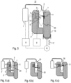
Fig. 4.a) to 4.c) show schematic views of different arrangements defining a radiation path. For ease of orientation, these arrangements are shown in relation to a simplified representation of the embodiment of the apparatus shown inFig. 3 , however, within the scope defined by the appended claims, the arrangements may be combined with other embodiments as well. -
Fig. 4.a) shows an arrangement of atransmitter 4 and a detector being arranged each in proximity of a first 1 and a second 2 positioning surface. Aradiation path 6 once traverses the space between the first and second positioning surface in a direction perpendicular to the positioning surfaces. - In the arrangement in
Fig. 4.b) a similar configuration as in 4.a) is shown. Here, the positions the transmitter and the detector are replaced by atransmitter head 14 and areceiver head 15.Transmitter 4 anddetector 5 are placed at some distance and twooptical fibers 13 connect each thetransmitter 4 with thetransmitter head 14 and thedetector 5 with thereceiver head 15, respectively. -
Fig. 4.c) shows an arrangement comprising twomirrors 11 positioned on each of the opposingpositioning surfaces radiation path 6 traverses the space in between the positioning surfaces four times on the way from thetransmitter 4 to thedetector 5. -
Fig. 5 shows schematic view of a further embodiment of anapparatus 10 according to the invention. Compared to the embodiment shown inFig. 3 , the apparatus in addition comprises a gas-flow introducing device 7. The gas-flow introducing device is operable to inflate or deflate thecontainer 20. Here, the situation during the measuring time is shown. As a preparing step, thecontainer 20 having deformable walls has been inflated by means of the gas-flow introducing device 7, such that opposing walls of the container are in contact with the first 1 and second 2 positioning surface. With this embodiment of the apparatus, a gas concentration inside the container may be measured directly after introduction of the filling gas. A succession of inflating and deflating may be applied in order to flush the container with a filling gas, until a previously specified composition of the gas inside the container is reached. This composition may e.g. be a low oxygen concentration, such as an oxygen concentration below 1 ‰ or even below 100 ppm, in particular below 10 ppm, further in particular below 1 ppm. -
Fig. 6.a), 6.b) and 6.c) show schematic views of the situation occurring in steps of an embodiment of the method according to the invention. An empty container, which may have the form of a flexible bag, is arranged between opposing positioningsurfaces container 20 is connected to the gas-flow introducing device 7. InFig. 6.b) , the container is inflated by introducing gas through anopening 23 of the container. Thereby a diameter D2 of the container is increased until it coincides with the distance D1 between the first and second positioning surface, which is indicated inFig. 6.a). Fig. 6.c) shows the situation during the measuring time, withelectromagnetic radiation 30 being transmitted from thetransmitter 4 via a reflection on thereflector 11 to thedetector 5. -
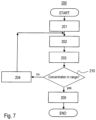
Fig. 7 shows amethod 200 of producing a sealed container containing a filling gas volume having a concentration of a monitored gas, in particular oxygen, lying in a predetermined concentration range, in particular a concentration below 100 ppm, in particular below 10 ppm, further in particular below 1 ppm. The method comprises the sequence of steps: - a) providing 201 a filling gas having a concentration of the monitored gas lying in the predetermined concentration range,
- b) at least once filling 202 a container with the provided filling gas,
- c) applying 203 the steps of the method according to the invention or any one of its embodiments to determine a concentration of the monitored gas.
Then, depending on the determined concentration thedecision 210 is made.
If the concentration lies outside the predetermined concentration range (arrow "no"), then the step - d) extracting 204 at least a part of the provided filling gas from the container is performed and steps b) and c) are repeated to arrive at the
decision 210 point again.
If the concentration lies in the predetermined concentration range (arrow "yes"), the step - e) sealing 205 the container is performed.
- As result, the sealed container fulfilling the predetermined requirements regarding the gas concentration of the monitored gas is produced.
-
- 1
- first positioning surface
- 2
- second positioning surface
- 2'
- second positioning element
- 3
- space between first and second positioning surface
- 4
- transmitter
- 5
- detector
- 6
- radiation path
- 7
- gas-flow introducing device
- 8
- control unit
- 9
- evaluation unit
- 10
- apparatus
- 11
- reflector
- 12
- actuator element
- 13
- optical fiber
- 14
- transmitter head
- 15
- receiver head
- 16
- manipulating element
- 17
- movement of manipulating element
- 20
- container
- 21
- first section of wall
- 22
- second section of wall
- 23
- opening
- 24
- movement of section of wall
- 30
- electromagnetic radiation
- D1
- distance (between first and second positioning surfaces)
- D2
- diameter (of the container)
- 100
- method (for measuring a concentration of a gas)
- 101, 102, 103, 104, 105
- steps of the method
- 110
- measuring time
- 200
- method (of producing a sealed container)
- 201, 202, 203, 204, 205
- steps of the method
- 210
- decision
Claims (14)
- Method (100) for measuring a concentration of a gas in a container having a wall with at least one deformable portion, the gas absorbing electromagnetic radiation at least in a specific spectral range, wherein the method comprises the steps of:- biasing (101) said deformable portion and a further portion of said wall opposite said deformable portion between first and second opposite positioning surfaces, thereby forming a biased volume of said container between said first and second opposite positioning surfaces and defining a length of a radiation path inside said biased volume,- during a measuring time (110), transmitting (102) electromagnetic radiation into said biased volume between said first and second opposite positioning surfaces and receiving (103) transmitted or reflected radiation of said transmitted radiation from said biased volume along said length of said radiation path,- relatively moving (104), during said measuring time, at least one of said deformable portion and of said further portion and at least one of said radiation paths, and- determining (105) said concentration of said gas from the radiation received,characterized in thatsaid transmitting (102), said receiving (103) and said relatively moving (104) are performed simultaneously,said relatively moving is induced by moving said first positioning surface of said opposite positioning surfaces with respect to said second positioning surface of said opposite positioning surfaces, thereby holding said length of said radiation path substantially constant,
and in thatsaid moving said first positioning surface holding said length of said radiation path substantially constant is one of:- a translation perpendicular to said radiation path,- a rotation around an axis along said radiation path, and- a tilting around a point defining said radiation path, such as a point on a reflector. - Method according to claim 1, wherein said relatively moving (104) is performed in a cyclic movement having a repetition time corresponding to said measuring time or to a fraction of said measuring time.
- Method according to claim 1 or 2, wherein the step of determining (105) said concentration is based on radiation received at points in time corresponding to different positions of at least one of said deformable portion and said further portion of the wall reached during said movement.
- Method according to any one of claims 1 to 3, wherein said transmitting (102) is performed by an electromagnetic radiation source (4), in particular a laser, having a spectral bandwidth narrower than said specific spectral range and with a tunable transmitter frequency and wherein said transmitter frequency is periodically swept over said specific spectral range.
- Method according to any one of claims 1 to 4, wherein said step of biasing (101) is performed by filling the container at least partially with a filling gas and thereby increasing a diameter of the container until said diameter extends between said first and second opposite positioning surfaces.
- Method according to any one of claims 1 to 5, wherein said step of biasing (101) is performed by moving at least one of said first and second opposing positioning surfaces towards at least one of said deformable portion and further portion of said wall.
- Method (200) of producing a sealed container containing a filling gas volume having a concentration of a monitored gas, in particular oxygen, lying in a predetermined concentration range, in particular a concentration below 100 ppm, in particular below 10 ppm, further in particular below 1 ppm, the method comprising:a) providing (201) a filling gas having a concentration of said monitored gas lying in said predetermined concentration range,b) at least once filling (202) a container with said provided filling gas,c) applying (203) the steps of the method according to any one of claims 1 to 6 to determine a concentration of said monitored gas,
if said concentration lies outside said predetermined concentration range:d) extracting (204) at least a part of said provided filling gas from said container and repeating steps b) and c), or
if said concentration lies in said predetermined concentration range:e) sealing (205) the container. - Method for producing a sealed container containing a liquid or solid content and a filling gas volume having a concentration of a monitored gas, in particular oxygen, lying in a predetermined concentration range, in particular a concentration below 100 ppm, in particular below 10 ppm, further in particular below 1 ppm, the method comprising filling the liquid or solid content into the container followed by the method according to claim 7.
- Apparatus (10) for performing the method according to any one of claims 1 to 8, wherein the apparatus (10) comprises:- a first positioning surface (1) of a manipulating element (16) and a second positioning surface (2) of at least a first positioning element, said first and second positioning surfaces (1, 2) defining a space (3) and a length of a radiation path (6) in between them;- a transmitter (4) for electromagnetic radiation in said specific spectral range and a detector (5) for electromagnetic radiation in said specific spectral range, said transmitter (4) and said detector (5) being arranged to define a radiation path (6) traversing said space (3) on the way from said transmitter (4) to said detector (5);- an actuator element (12) being mechanically coupled to the manipulating element (16) configured to manipulate at least a part the wall of a container (20), once a container (20) is inserted between said first and second positioning surfaces (1, 2), thereby moving a section of said wall of the container (20) relatively to at least one of said radiation paths and across at least one of said radiation paths, said section being adjacent to at least one of said first and second positioning surfaces (1, 2);- a control unit (8) operably connected to said transmitter (4), to said detector (5) and to said actuator element (12) ;- an evaluation unit (9) operably connected to said detector (5) and configured to determine a gas concentration based on the electromagnetic radiation received by the detector (5),characterized in that
said first positioning surface (1) is arranged on said manipulating element (16), said manipulating element (16) being movable with respect to said second positioning surface (2), in particular being translatable and/or rotatable and/or pivotable with respect to said second positioning surface (2), wherein said transmitter (4), detector (5) and actuator element (12) are arranged for simultaneously performing said transmitting, said receiving and said relatively moving, wherein the apparatus (10) is configured such that a movement of the manipulating element (16) leads to a movement of the first positioning surface (1), which holds the length of the radiation path (6) substantially constant and wherein the movement of the first positioning surface (1) is one of:- a translation perpendicular to the radiation path (6),- a rotation around an axis along the radiation path (6), and- a tilting around a point defining the radiation path (6), such as a point on a reflector (11). - Apparatus (10) according to claim 9, wherein said first and second positioning surfaces (1, 2) are flat and are arranged substantially parallel to each other.
- Apparatus (10) according to claim 10, wherein said first positioning element is translatable parallel to said second positioning surface (2).
- Apparatus (10) according to any one of claims 9 to 11, wherein the apparatus further comprises a reflector (11), and wherein at least one of said first and second positioning surfaces is rigidly connected to said reflector (11) for said electromagnetic radiation.
- Apparatus (10) according to any one of claims 9 to 12, wherein the container comprises an opening (23), and the apparatus further comprises a gas-flow introducing device (7) adapted to be connected to said opening (23) of said container (20) and is operable to inflate and deflate the container (20).
- Filling facility for filling containers (20), each container (20) having wall delimiting an inner volume of said container (20), said wall having at least one deformable portion, the filling facility comprising an apparatus (10) according to any one of the claims 9 to 13.
Applications Claiming Priority (2)
| Application Number | Priority Date | Filing Date | Title |
|---|---|---|---|
| CH14712016 | 2016-11-04 | ||
| PCT/EP2017/077943 WO2018083107A1 (en) | 2016-11-04 | 2017-11-01 | Method and apparatus for measuring a concentration of a gas |
Publications (2)
| Publication Number | Publication Date |
|---|---|
| EP3535563A1 EP3535563A1 (en) | 2019-09-11 |
| EP3535563B1 true EP3535563B1 (en) | 2023-06-07 |
Family
ID=60331586
Family Applications (1)
| Application Number | Title | Priority Date | Filing Date |
|---|---|---|---|
| EP17798154.5A Active EP3535563B1 (en) | 2016-11-04 | 2017-11-01 | Method and apparatus for measuring a concentration of a gas |
Country Status (8)
| Country | Link |
|---|---|
| US (1) | US11002673B2 (en) |
| EP (1) | EP3535563B1 (en) |
| JP (1) | JP7210442B2 (en) |
| KR (1) | KR102406989B1 (en) |
| CN (1) | CN109863385B (en) |
| DK (1) | DK3535563T3 (en) |
| RU (1) | RU2752286C2 (en) |
| WO (1) | WO2018083107A1 (en) |
Families Citing this family (14)
| Publication number | Priority date | Publication date | Assignee | Title |
|---|---|---|---|---|
| CN110214006A (en) * | 2017-01-31 | 2019-09-06 | 威尔科股份公司 | Method for measuring gas concentration |
| JP7313383B2 (en) * | 2018-06-07 | 2023-07-24 | ヴィルコ・アーゲー | Apparatus for detecting gas in the headspace of a container |
| JP2021067563A (en) * | 2019-10-24 | 2021-04-30 | ゼネラルパッカー株式会社 | Gas concentration measuring device for wrapping container, wrapping machine having the same, and method for measuring concentration of gas in wrapping machine |
| JP2021067562A (en) * | 2019-10-24 | 2021-04-30 | ゼネラルパッカー株式会社 | Gas concentration measuring device for wrapping container, wrapping machine having the same, and method for measuring concentration of gas in wrapping machine |
| JP2021067564A (en) * | 2019-10-24 | 2021-04-30 | ゼネラルパッカー株式会社 | Gas concentration measuring device for wrapping container, wrapping machine having the same, and method for measuring concentration of gas in wrapping machine |
| JP2021067633A (en) * | 2019-10-28 | 2021-04-30 | ゼネラルパッカー株式会社 | Method of measuring gas concentration in packaging bag |
| JP2021067631A (en) * | 2019-10-28 | 2021-04-30 | ゼネラルパッカー株式会社 | Method of measuring gas concentration in packaging bag |
| JP2021067634A (en) * | 2019-10-28 | 2021-04-30 | ゼネラルパッカー株式会社 | Device for measuring gas concentration in packaging bag |
| JP7357918B2 (en) * | 2019-10-28 | 2023-10-10 | ゼネラルパッカー株式会社 | Gas concentration measuring device inside packaging bag |
| JP7769390B2 (en) * | 2020-05-14 | 2025-11-13 | ガスポロックス エイビー | System and method for determining the concentration of a gas in a container - Patents.com |
| JP7379283B2 (en) * | 2020-06-23 | 2023-11-14 | 新光電気工業株式会社 | sensor module |
| JP2022176601A (en) * | 2021-05-17 | 2022-11-30 | ゼネラルパッカー株式会社 | A packaging bag gas concentration measuring device, a packaging machine equipped with the same, and a packaging bag gas concentration measuring method. |
| JP2022176602A (en) * | 2021-05-17 | 2022-11-30 | ゼネラルパッカー株式会社 | Packaging bag gas concentration measuring device and packaging bag gas concentration measuring method |
| JP7607921B2 (en) * | 2021-05-17 | 2025-01-06 | ゼネラルパッカー株式会社 | Packaging bag gas concentration measuring device |
Citations (1)
| Publication number | Priority date | Publication date | Assignee | Title |
|---|---|---|---|---|
| EP1927831A1 (en) * | 2006-11-30 | 2008-06-04 | Siemens Aktiengesellschaft | Method and apparatus for reducing fringe interference of light |
Family Cites Families (27)
| Publication number | Priority date | Publication date | Assignee | Title |
|---|---|---|---|---|
| US4522494A (en) * | 1982-07-07 | 1985-06-11 | The United States Of America As Represented By The Department Of Health And Human Services | Non-invasive optical assessment of platelet viability |
| US5473161A (en) * | 1994-06-21 | 1995-12-05 | The Coca-Cola Company | Method for testing carbonation loss from beverage bottles using IR spectroscopy |
| FI107194B (en) * | 1996-03-14 | 2001-06-15 | Instrumentarium Oy | Analysis of gas mixtures by infrared method |
| US5728439A (en) * | 1996-12-04 | 1998-03-17 | Ppg Industries, Inc. | Multilayer packaging material for oxygen sensitive food and beverage |
| FI101749B (en) * | 1996-12-30 | 1998-08-14 | Instrumentarium Oy | Accurate measurement of concentration for a gas component in a gas mixture, in which other components affect the concentration determination |
| US6082184A (en) * | 1997-05-27 | 2000-07-04 | Martin Lehmann | Method for leak testing and leak testing apparatus |
| JP2002202251A (en) * | 2000-12-28 | 2002-07-19 | Anritsu Corp | Gas detector |
| JP2003083722A (en) * | 2001-09-14 | 2003-03-19 | Toto Ltd | Shape measurement method and device using laser projection |
| US7151260B2 (en) * | 2003-03-03 | 2006-12-19 | Advanced Fuel Research, Inc. | Analyzer for measuring multiple gases |
| CA2461328A1 (en) * | 2004-03-24 | 2005-09-24 | Robert Anthony Crane | A multiplexed type of spectrophone |
| EP1828749A1 (en) * | 2004-12-17 | 2007-09-05 | Honeywell Analytics AG | Transmitter unit for open path gas detector |
| JP2008070314A (en) * | 2006-09-15 | 2008-03-27 | Anritsu Corp | Gas detector |
| JP5124719B2 (en) * | 2007-07-06 | 2013-01-23 | ゼネラルパッカー株式会社 | Gas concentration measurement method for packaging machines |
| SE533411C2 (en) * | 2008-08-28 | 2010-09-21 | Senseair Ab | A spectral analysis of a compressed gas, such as a gas at small gas concentrations at atmospheric pressure, adapted arrangement |
| JP5389404B2 (en) * | 2008-09-18 | 2014-01-15 | 生活協同組合コープさっぽろ | Delivery map creation device, delivery map creation method, and delivery map creation program |
| JP5337953B2 (en) * | 2009-01-14 | 2013-11-06 | ゼネラルパッカー株式会社 | Gas concentration measuring method and gas concentration measuring device |
| DE102009055320B4 (en) * | 2009-12-24 | 2011-09-01 | Humedics Gmbh | Measuring device and method for examining a sample gas by means of infrared absorption spectroscopy |
| IT1401562B1 (en) * | 2010-06-28 | 2013-07-26 | L Pro S R L | EQUIPMENT FOR MEASURING A GAS CONCENTRATION IN A CLOSED CONTAINER |
| JP5686662B2 (en) * | 2011-04-28 | 2015-03-18 | 日立造船株式会社 | Nondestructive inspection device for oxygen concentration in bag-like containers |
| ES2536091T3 (en) * | 2012-05-24 | 2015-05-20 | Air Products And Chemicals, Inc. | Apparatus for measuring the true content of a gas cylinder under pressure |
| JP2014115198A (en) * | 2012-12-10 | 2014-06-26 | Mitsubishi Heavy Ind Ltd | Gas sampling bag and laser measuring device |
| EP3208603B1 (en) * | 2013-05-27 | 2019-10-02 | GasPorOx AB | System and method for determining a concentration of a gas in a container |
| DE102014202595B4 (en) * | 2014-02-13 | 2023-06-07 | Robert Bosch Gmbh | Method and device for determining oxygen in a closed container |
| US20150241359A1 (en) * | 2014-02-27 | 2015-08-27 | General Electric Company | Method and gas analysis unit for determining a chance to enable a zeroing of gas analysis |
| GB201500918D0 (en) * | 2015-01-20 | 2015-03-04 | Universit� Libre De Bruxelles | Measuring apparatus and method |
| DE102016003284B4 (en) * | 2016-03-18 | 2022-05-19 | Dräger Safety AG & Co. KGaA | Gas measuring device with a test device for checking a gas sensor |
| US10775297B2 (en) * | 2016-08-24 | 2020-09-15 | Ecotec Solutions, Inc. | Laser absorption spectroscopy system and method for discrimination of a first and a second gas |
-
2017
- 2017-11-01 CN CN201780068057.7A patent/CN109863385B/en active Active
- 2017-11-01 DK DK17798154.5T patent/DK3535563T3/en active
- 2017-11-01 JP JP2019522655A patent/JP7210442B2/en active Active
- 2017-11-01 EP EP17798154.5A patent/EP3535563B1/en active Active
- 2017-11-01 KR KR1020197013749A patent/KR102406989B1/en active Active
- 2017-11-01 US US16/347,653 patent/US11002673B2/en active Active
- 2017-11-01 WO PCT/EP2017/077943 patent/WO2018083107A1/en not_active Ceased
- 2017-11-01 RU RU2019117045A patent/RU2752286C2/en active
Patent Citations (1)
| Publication number | Priority date | Publication date | Assignee | Title |
|---|---|---|---|---|
| EP1927831A1 (en) * | 2006-11-30 | 2008-06-04 | Siemens Aktiengesellschaft | Method and apparatus for reducing fringe interference of light |
Also Published As
| Publication number | Publication date |
|---|---|
| CN109863385A (en) | 2019-06-07 |
| RU2019117045A3 (en) | 2021-02-04 |
| JP7210442B2 (en) | 2023-01-23 |
| DK3535563T3 (en) | 2023-08-21 |
| CN109863385B (en) | 2022-10-04 |
| KR20190079630A (en) | 2019-07-05 |
| KR102406989B1 (en) | 2022-06-10 |
| RU2752286C2 (en) | 2021-07-26 |
| JP2019534457A (en) | 2019-11-28 |
| EP3535563A1 (en) | 2019-09-11 |
| CA3041075A1 (en) | 2018-05-11 |
| US20190317014A1 (en) | 2019-10-17 |
| RU2019117045A (en) | 2020-12-04 |
| US11002673B2 (en) | 2021-05-11 |
| WO2018083107A1 (en) | 2018-05-11 |
Similar Documents
| Publication | Publication Date | Title |
|---|---|---|
| US11002673B2 (en) | Method for measuring a concentration of a gas | |
| US7948626B2 (en) | Method for the automated measurement of gas pressure and concentration inside sealed containers | |
| JP5866013B2 (en) | Method and apparatus for determining a substance by using terahertz radiation | |
| JP7075862B2 (en) | Analysis equipment | |
| EP3004820A1 (en) | System and method for determining a concentration of a gas in a container | |
| JP7135608B2 (en) | Gas absorption spectroscopy device and gas absorption spectroscopy method | |
| WO2018141752A1 (en) | Method for measuring a concentration of a gas | |
| JP7357918B2 (en) | Gas concentration measuring device inside packaging bag | |
| ITMI20120493A1 (en) | EQUIPMENT FOR NON-DESTRUCTIVE CONTROL OF INTEGRITY AND / OR SUITABILITY OF SEALED PACKAGES | |
| EP3803352B1 (en) | Apparatus for detecting a gas in a headspace of a container | |
| JP2021067634A (en) | Device for measuring gas concentration in packaging bag | |
| EP3413032B1 (en) | An arrangement and method for measuring the gas content in the head space of a closed container and an automatic filling and/or packaging plant using such an arrangement | |
| CA3041075C (en) | Method and apparatus for measuring a concentration of a gas | |
| JP7343169B2 (en) | Gas concentration measurement method and gas concentration measurement device for sealed packaging containers | |
| JP7350312B2 (en) | Method for measuring gas concentration in packaging containers | |
| US20250283810A1 (en) | System and method for determining at least one property of a porous medium | |
| JP2021067631A (en) | Method of measuring gas concentration in packaging bag | |
| Rigamonti et al. | A novel microfluidic sensing platform based on miniature rectangular glass capillaries and optical readout | |
| Zielcke et al. | A new calibration system for lightweight, compact and mobile Cavity-Enhanced Differential Optical Absorption Spectroscopy instruments | |
| Schwerdtfeger et al. | Discrete sampling of continuous wave terahertz radiation |
Legal Events
| Date | Code | Title | Description |
|---|---|---|---|
| STAA | Information on the status of an ep patent application or granted ep patent |
Free format text: STATUS: UNKNOWN |
|
| STAA | Information on the status of an ep patent application or granted ep patent |
Free format text: STATUS: THE INTERNATIONAL PUBLICATION HAS BEEN MADE |
|
| PUAI | Public reference made under article 153(3) epc to a published international application that has entered the european phase |
Free format text: ORIGINAL CODE: 0009012 |
|
| STAA | Information on the status of an ep patent application or granted ep patent |
Free format text: STATUS: REQUEST FOR EXAMINATION WAS MADE |
|
| 17P | Request for examination filed |
Effective date: 20190415 |
|
| AK | Designated contracting states |
Kind code of ref document: A1 Designated state(s): AL AT BE BG CH CY CZ DE DK EE ES FI FR GB GR HR HU IE IS IT LI LT LU LV MC MK MT NL NO PL PT RO RS SE SI SK SM TR |
|
| AX | Request for extension of the european patent |
Extension state: BA ME |
|
| DAV | Request for validation of the european patent (deleted) | ||
| DAX | Request for extension of the european patent (deleted) | ||
| STAA | Information on the status of an ep patent application or granted ep patent |
Free format text: STATUS: EXAMINATION IS IN PROGRESS |
|
| 17Q | First examination report despatched |
Effective date: 20200228 |
|
| GRAP | Despatch of communication of intention to grant a patent |
Free format text: ORIGINAL CODE: EPIDOSNIGR1 |
|
| STAA | Information on the status of an ep patent application or granted ep patent |
Free format text: STATUS: GRANT OF PATENT IS INTENDED |
|
| RIC1 | Information provided on ipc code assigned before grant |
Ipc: G01N 21/90 20060101ALN20220304BHEP Ipc: G01N 21/39 20060101ALN20220304BHEP Ipc: G01N 21/359 20140101ALN20220304BHEP Ipc: G01N 21/3504 20140101ALN20220304BHEP Ipc: B65B 31/00 20060101ALI20220304BHEP Ipc: G01N 21/17 20060101ALI20220304BHEP Ipc: G01N 21/03 20060101AFI20220304BHEP |
|
| INTG | Intention to grant announced |
Effective date: 20220323 |
|
| GRAJ | Information related to disapproval of communication of intention to grant by the applicant or resumption of examination proceedings by the epo deleted |
Free format text: ORIGINAL CODE: EPIDOSDIGR1 |
|
| STAA | Information on the status of an ep patent application or granted ep patent |
Free format text: STATUS: EXAMINATION IS IN PROGRESS |
|
| INTC | Intention to grant announced (deleted) | ||
| GRAP | Despatch of communication of intention to grant a patent |
Free format text: ORIGINAL CODE: EPIDOSNIGR1 |
|
| RIC1 | Information provided on ipc code assigned before grant |
Ipc: G01N 21/90 20060101ALN20220726BHEP Ipc: G01N 21/39 20060101ALN20220726BHEP Ipc: G01N 21/359 20140101ALN20220726BHEP Ipc: G01N 21/3504 20140101ALN20220726BHEP Ipc: B65B 31/00 20060101ALI20220726BHEP Ipc: G01N 21/17 20060101ALI20220726BHEP Ipc: G01N 21/03 20060101AFI20220726BHEP |
|
| STAA | Information on the status of an ep patent application or granted ep patent |
Free format text: STATUS: GRANT OF PATENT IS INTENDED |
|
| INTG | Intention to grant announced |
Effective date: 20220901 |
|
| GRAS | Grant fee paid |
Free format text: ORIGINAL CODE: EPIDOSNIGR3 |
|
| GRAA | (expected) grant |
Free format text: ORIGINAL CODE: 0009210 |
|
| STAA | Information on the status of an ep patent application or granted ep patent |
Free format text: STATUS: THE PATENT HAS BEEN GRANTED |
|
| AK | Designated contracting states |
Kind code of ref document: B1 Designated state(s): AL AT BE BG CH CY CZ DE DK EE ES FI FR GB GR HR HU IE IS IT LI LT LU LV MC MK MT NL NO PL PT RO RS SE SI SK SM TR |
|
| REG | Reference to a national code |
Ref country code: GB Ref legal event code: FG4D |
|
| REG | Reference to a national code |
Ref country code: CH Ref legal event code: EP Ref country code: AT Ref legal event code: REF Ref document number: 1576506 Country of ref document: AT Kind code of ref document: T Effective date: 20230615 |
|
| REG | Reference to a national code |
Ref country code: DE Ref legal event code: R096 Ref document number: 602017069754 Country of ref document: DE |
|
| REG | Reference to a national code |
Ref country code: NL Ref legal event code: FP |
|
| REG | Reference to a national code |
Ref country code: DK Ref legal event code: T3 Effective date: 20230816 |
|
| REG | Reference to a national code |
Ref country code: SE Ref legal event code: TRGR |
|
| REG | Reference to a national code |
Ref country code: LT Ref legal event code: MG9D |
|
| PG25 | Lapsed in a contracting state [announced via postgrant information from national office to epo] |
Ref country code: NO Free format text: LAPSE BECAUSE OF FAILURE TO SUBMIT A TRANSLATION OF THE DESCRIPTION OR TO PAY THE FEE WITHIN THE PRESCRIBED TIME-LIMIT Effective date: 20230907 Ref country code: ES Free format text: LAPSE BECAUSE OF FAILURE TO SUBMIT A TRANSLATION OF THE DESCRIPTION OR TO PAY THE FEE WITHIN THE PRESCRIBED TIME-LIMIT Effective date: 20230607 |
|
| REG | Reference to a national code |
Ref country code: AT Ref legal event code: MK05 Ref document number: 1576506 Country of ref document: AT Kind code of ref document: T Effective date: 20230607 |
|
| PG25 | Lapsed in a contracting state [announced via postgrant information from national office to epo] |
Ref country code: RS Free format text: LAPSE BECAUSE OF FAILURE TO SUBMIT A TRANSLATION OF THE DESCRIPTION OR TO PAY THE FEE WITHIN THE PRESCRIBED TIME-LIMIT Effective date: 20230607 Ref country code: LV Free format text: LAPSE BECAUSE OF FAILURE TO SUBMIT A TRANSLATION OF THE DESCRIPTION OR TO PAY THE FEE WITHIN THE PRESCRIBED TIME-LIMIT Effective date: 20230607 Ref country code: LT Free format text: LAPSE BECAUSE OF FAILURE TO SUBMIT A TRANSLATION OF THE DESCRIPTION OR TO PAY THE FEE WITHIN THE PRESCRIBED TIME-LIMIT Effective date: 20230607 Ref country code: HR Free format text: LAPSE BECAUSE OF FAILURE TO SUBMIT A TRANSLATION OF THE DESCRIPTION OR TO PAY THE FEE WITHIN THE PRESCRIBED TIME-LIMIT Effective date: 20230607 Ref country code: GR Free format text: LAPSE BECAUSE OF FAILURE TO SUBMIT A TRANSLATION OF THE DESCRIPTION OR TO PAY THE FEE WITHIN THE PRESCRIBED TIME-LIMIT Effective date: 20230908 |
|
| PG25 | Lapsed in a contracting state [announced via postgrant information from national office to epo] |
Ref country code: FI Free format text: LAPSE BECAUSE OF FAILURE TO SUBMIT A TRANSLATION OF THE DESCRIPTION OR TO PAY THE FEE WITHIN THE PRESCRIBED TIME-LIMIT Effective date: 20230607 |
|
| PG25 | Lapsed in a contracting state [announced via postgrant information from national office to epo] |
Ref country code: SK Free format text: LAPSE BECAUSE OF FAILURE TO SUBMIT A TRANSLATION OF THE DESCRIPTION OR TO PAY THE FEE WITHIN THE PRESCRIBED TIME-LIMIT Effective date: 20230607 |
|
| PG25 | Lapsed in a contracting state [announced via postgrant information from national office to epo] |
Ref country code: IS Free format text: LAPSE BECAUSE OF FAILURE TO SUBMIT A TRANSLATION OF THE DESCRIPTION OR TO PAY THE FEE WITHIN THE PRESCRIBED TIME-LIMIT Effective date: 20231007 |
|
| PG25 | Lapsed in a contracting state [announced via postgrant information from national office to epo] |
Ref country code: SM Free format text: LAPSE BECAUSE OF FAILURE TO SUBMIT A TRANSLATION OF THE DESCRIPTION OR TO PAY THE FEE WITHIN THE PRESCRIBED TIME-LIMIT Effective date: 20230607 Ref country code: SK Free format text: LAPSE BECAUSE OF FAILURE TO SUBMIT A TRANSLATION OF THE DESCRIPTION OR TO PAY THE FEE WITHIN THE PRESCRIBED TIME-LIMIT Effective date: 20230607 Ref country code: RO Free format text: LAPSE BECAUSE OF FAILURE TO SUBMIT A TRANSLATION OF THE DESCRIPTION OR TO PAY THE FEE WITHIN THE PRESCRIBED TIME-LIMIT Effective date: 20230607 Ref country code: PT Free format text: LAPSE BECAUSE OF FAILURE TO SUBMIT A TRANSLATION OF THE DESCRIPTION OR TO PAY THE FEE WITHIN THE PRESCRIBED TIME-LIMIT Effective date: 20231009 Ref country code: IS Free format text: LAPSE BECAUSE OF FAILURE TO SUBMIT A TRANSLATION OF THE DESCRIPTION OR TO PAY THE FEE WITHIN THE PRESCRIBED TIME-LIMIT Effective date: 20231007 Ref country code: EE Free format text: LAPSE BECAUSE OF FAILURE TO SUBMIT A TRANSLATION OF THE DESCRIPTION OR TO PAY THE FEE WITHIN THE PRESCRIBED TIME-LIMIT Effective date: 20230607 Ref country code: CZ Free format text: LAPSE BECAUSE OF FAILURE TO SUBMIT A TRANSLATION OF THE DESCRIPTION OR TO PAY THE FEE WITHIN THE PRESCRIBED TIME-LIMIT Effective date: 20230607 Ref country code: AT Free format text: LAPSE BECAUSE OF FAILURE TO SUBMIT A TRANSLATION OF THE DESCRIPTION OR TO PAY THE FEE WITHIN THE PRESCRIBED TIME-LIMIT Effective date: 20230607 |
|
| PG25 | Lapsed in a contracting state [announced via postgrant information from national office to epo] |
Ref country code: PL Free format text: LAPSE BECAUSE OF FAILURE TO SUBMIT A TRANSLATION OF THE DESCRIPTION OR TO PAY THE FEE WITHIN THE PRESCRIBED TIME-LIMIT Effective date: 20230607 |
|
| REG | Reference to a national code |
Ref country code: DE Ref legal event code: R097 Ref document number: 602017069754 Country of ref document: DE |
|
| PLBE | No opposition filed within time limit |
Free format text: ORIGINAL CODE: 0009261 |
|
| STAA | Information on the status of an ep patent application or granted ep patent |
Free format text: STATUS: NO OPPOSITION FILED WITHIN TIME LIMIT |
|
| PG25 | Lapsed in a contracting state [announced via postgrant information from national office to epo] |
Ref country code: SI Free format text: LAPSE BECAUSE OF FAILURE TO SUBMIT A TRANSLATION OF THE DESCRIPTION OR TO PAY THE FEE WITHIN THE PRESCRIBED TIME-LIMIT Effective date: 20230607 |
|
| 26N | No opposition filed |
Effective date: 20240308 |
|
| PG25 | Lapsed in a contracting state [announced via postgrant information from national office to epo] |
Ref country code: SI Free format text: LAPSE BECAUSE OF FAILURE TO SUBMIT A TRANSLATION OF THE DESCRIPTION OR TO PAY THE FEE WITHIN THE PRESCRIBED TIME-LIMIT Effective date: 20230607 |
|
| PG25 | Lapsed in a contracting state [announced via postgrant information from national office to epo] |
Ref country code: MC Free format text: LAPSE BECAUSE OF FAILURE TO SUBMIT A TRANSLATION OF THE DESCRIPTION OR TO PAY THE FEE WITHIN THE PRESCRIBED TIME-LIMIT Effective date: 20230607 |
|
| PG25 | Lapsed in a contracting state [announced via postgrant information from national office to epo] |
Ref country code: LU Free format text: LAPSE BECAUSE OF NON-PAYMENT OF DUE FEES Effective date: 20231101 |
|
| PG25 | Lapsed in a contracting state [announced via postgrant information from national office to epo] |
Ref country code: MC Free format text: LAPSE BECAUSE OF FAILURE TO SUBMIT A TRANSLATION OF THE DESCRIPTION OR TO PAY THE FEE WITHIN THE PRESCRIBED TIME-LIMIT Effective date: 20230607 Ref country code: LU Free format text: LAPSE BECAUSE OF NON-PAYMENT OF DUE FEES Effective date: 20231101 |
|
| PG25 | Lapsed in a contracting state [announced via postgrant information from national office to epo] |
Ref country code: BG Free format text: LAPSE BECAUSE OF FAILURE TO SUBMIT A TRANSLATION OF THE DESCRIPTION OR TO PAY THE FEE WITHIN THE PRESCRIBED TIME-LIMIT Effective date: 20230607 |
|
| PG25 | Lapsed in a contracting state [announced via postgrant information from national office to epo] |
Ref country code: BG Free format text: LAPSE BECAUSE OF FAILURE TO SUBMIT A TRANSLATION OF THE DESCRIPTION OR TO PAY THE FEE WITHIN THE PRESCRIBED TIME-LIMIT Effective date: 20230607 |
|
| PG25 | Lapsed in a contracting state [announced via postgrant information from national office to epo] |
Ref country code: CY Free format text: LAPSE BECAUSE OF FAILURE TO SUBMIT A TRANSLATION OF THE DESCRIPTION OR TO PAY THE FEE WITHIN THE PRESCRIBED TIME-LIMIT; INVALID AB INITIO Effective date: 20171101 |
|
| PG25 | Lapsed in a contracting state [announced via postgrant information from national office to epo] |
Ref country code: HU Free format text: LAPSE BECAUSE OF FAILURE TO SUBMIT A TRANSLATION OF THE DESCRIPTION OR TO PAY THE FEE WITHIN THE PRESCRIBED TIME-LIMIT; INVALID AB INITIO Effective date: 20171101 |
|
| PGFP | Annual fee paid to national office [announced via postgrant information from national office to epo] |
Ref country code: FR Payment date: 20250930 Year of fee payment: 9 |
|
| PGFP | Annual fee paid to national office [announced via postgrant information from national office to epo] |
Ref country code: NL Payment date: 20251003 Year of fee payment: 9 |
|
| REG | Reference to a national code |
Ref country code: CH Ref legal event code: U11 Free format text: ST27 STATUS EVENT CODE: U-0-0-U10-U11 (AS PROVIDED BY THE NATIONAL OFFICE) Effective date: 20251201 |
|
| PG25 | Lapsed in a contracting state [announced via postgrant information from national office to epo] |
Ref country code: TR Free format text: LAPSE BECAUSE OF FAILURE TO SUBMIT A TRANSLATION OF THE DESCRIPTION OR TO PAY THE FEE WITHIN THE PRESCRIBED TIME-LIMIT Effective date: 20230607 |
|
| PGFP | Annual fee paid to national office [announced via postgrant information from national office to epo] |
Ref country code: DE Payment date: 20250930 Year of fee payment: 9 |
|
| PGFP | Annual fee paid to national office [announced via postgrant information from national office to epo] |
Ref country code: GB Payment date: 20251001 Year of fee payment: 9 |
|
| PGFP | Annual fee paid to national office [announced via postgrant information from national office to epo] |
Ref country code: DK Payment date: 20251112 Year of fee payment: 9 Ref country code: IT Payment date: 20251022 Year of fee payment: 9 |
|
| PGFP | Annual fee paid to national office [announced via postgrant information from national office to epo] |
Ref country code: BE Payment date: 20251003 Year of fee payment: 9 |
|
| PGFP | Annual fee paid to national office [announced via postgrant information from national office to epo] |
Ref country code: CH Payment date: 20251201 Year of fee payment: 9 Ref country code: SE Payment date: 20251001 Year of fee payment: 9 |
|
| PGFP | Annual fee paid to national office [announced via postgrant information from national office to epo] |
Ref country code: IE Payment date: 20251001 Year of fee payment: 9 |