EP1927831A1 - Method and apparatus for reducing fringe interference of light - Google Patents
Method and apparatus for reducing fringe interference of light Download PDFInfo
- Publication number
- EP1927831A1 EP1927831A1 EP06024845A EP06024845A EP1927831A1 EP 1927831 A1 EP1927831 A1 EP 1927831A1 EP 06024845 A EP06024845 A EP 06024845A EP 06024845 A EP06024845 A EP 06024845A EP 1927831 A1 EP1927831 A1 EP 1927831A1
- Authority
- EP
- European Patent Office
- Prior art keywords
- optical
- cavity
- length
- wavelength
- etalon
- Prior art date
- Legal status (The legal status is an assumption and is not a legal conclusion. Google has not performed a legal analysis and makes no representation as to the accuracy of the status listed.)
- Granted
Links
- 238000000034 method Methods 0.000 title claims abstract description 11
- 230000003287 optical effect Effects 0.000 claims abstract description 60
- BJQHLKABXJIVAM-UHFFFAOYSA-N bis(2-ethylhexyl) phthalate Chemical compound CCCCC(CC)COC(=O)C1=CC=CC=C1C(=O)OCC(CC)CCCC BJQHLKABXJIVAM-UHFFFAOYSA-N 0.000 description 34
- 230000000694 effects Effects 0.000 description 8
- 238000010521 absorption reaction Methods 0.000 description 6
- 230000005540 biological transmission Effects 0.000 description 5
- 238000013459 approach Methods 0.000 description 3
- 238000010586 diagram Methods 0.000 description 3
- 239000000203 mixture Substances 0.000 description 3
- 230000035945 sensitivity Effects 0.000 description 3
- 238000012935 Averaging Methods 0.000 description 2
- 230000001419 dependent effect Effects 0.000 description 2
- 238000013461 design Methods 0.000 description 2
- 230000005520 electrodynamics Effects 0.000 description 2
- 230000000737 periodic effect Effects 0.000 description 2
- 238000004458 analytical method Methods 0.000 description 1
- 238000000576 coating method Methods 0.000 description 1
- 238000001514 detection method Methods 0.000 description 1
- 238000006073 displacement reaction Methods 0.000 description 1
- 238000003780 insertion Methods 0.000 description 1
- 230000037431 insertion Effects 0.000 description 1
- 238000001285 laser absorption spectroscopy Methods 0.000 description 1
- 238000002310 reflectometry Methods 0.000 description 1
- 238000004611 spectroscopical analysis Methods 0.000 description 1
Images


Classifications
-
- G—PHYSICS
- G01—MEASURING; TESTING
- G01J—MEASUREMENT OF INTENSITY, VELOCITY, SPECTRAL CONTENT, POLARISATION, PHASE OR PULSE CHARACTERISTICS OF INFRARED, VISIBLE OR ULTRAVIOLET LIGHT; COLORIMETRY; RADIATION PYROMETRY
- G01J3/00—Spectrometry; Spectrophotometry; Monochromators; Measuring colours
- G01J3/28—Investigating the spectrum
- G01J3/42—Absorption spectrometry; Double beam spectrometry; Flicker spectrometry; Reflection spectrometry
- G01J3/433—Modulation spectrometry; Derivative spectrometry
- G01J3/4338—Frequency modulated spectrometry
-
- G—PHYSICS
- G01—MEASURING; TESTING
- G01J—MEASUREMENT OF INTENSITY, VELOCITY, SPECTRAL CONTENT, POLARISATION, PHASE OR PULSE CHARACTERISTICS OF INFRARED, VISIBLE OR ULTRAVIOLET LIGHT; COLORIMETRY; RADIATION PYROMETRY
- G01J3/00—Spectrometry; Spectrophotometry; Monochromators; Measuring colours
- G01J3/02—Details
- G01J3/0262—Constructional arrangements for removing stray light
-
- G—PHYSICS
- G01—MEASURING; TESTING
- G01N—INVESTIGATING OR ANALYSING MATERIALS BY DETERMINING THEIR CHEMICAL OR PHYSICAL PROPERTIES
- G01N21/00—Investigating or analysing materials by the use of optical means, i.e. using sub-millimetre waves, infrared, visible or ultraviolet light
- G01N21/01—Arrangements or apparatus for facilitating the optical investigation
- G01N21/03—Cuvette constructions
- G01N21/0303—Optical path conditioning in cuvettes, e.g. windows; adapted optical elements or systems; path modifying or adjustment
-
- G—PHYSICS
- G01—MEASURING; TESTING
- G01N—INVESTIGATING OR ANALYSING MATERIALS BY DETERMINING THEIR CHEMICAL OR PHYSICAL PROPERTIES
- G01N21/00—Investigating or analysing materials by the use of optical means, i.e. using sub-millimetre waves, infrared, visible or ultraviolet light
- G01N21/17—Systems in which incident light is modified in accordance with the properties of the material investigated
- G01N21/1717—Systems in which incident light is modified in accordance with the properties of the material investigated with a modulation of one or more physical properties of the sample during the optical investigation, e.g. electro-reflectance
-
- G—PHYSICS
- G01—MEASURING; TESTING
- G01N—INVESTIGATING OR ANALYSING MATERIALS BY DETERMINING THEIR CHEMICAL OR PHYSICAL PROPERTIES
- G01N21/00—Investigating or analysing materials by the use of optical means, i.e. using sub-millimetre waves, infrared, visible or ultraviolet light
- G01N21/17—Systems in which incident light is modified in accordance with the properties of the material investigated
- G01N21/25—Colour; Spectral properties, i.e. comparison of effect of material on the light at two or more different wavelengths or wavelength bands
- G01N21/31—Investigating relative effect of material at wavelengths characteristic of specific elements or molecules, e.g. atomic absorption spectrometry
- G01N21/39—Investigating relative effect of material at wavelengths characteristic of specific elements or molecules, e.g. atomic absorption spectrometry using tunable lasers
-
- G—PHYSICS
- G01—MEASURING; TESTING
- G01N—INVESTIGATING OR ANALYSING MATERIALS BY DETERMINING THEIR CHEMICAL OR PHYSICAL PROPERTIES
- G01N21/00—Investigating or analysing materials by the use of optical means, i.e. using sub-millimetre waves, infrared, visible or ultraviolet light
- G01N21/01—Arrangements or apparatus for facilitating the optical investigation
- G01N21/03—Cuvette constructions
- G01N2021/0389—Windows
-
- G—PHYSICS
- G01—MEASURING; TESTING
- G01N—INVESTIGATING OR ANALYSING MATERIALS BY DETERMINING THEIR CHEMICAL OR PHYSICAL PROPERTIES
- G01N21/00—Investigating or analysing materials by the use of optical means, i.e. using sub-millimetre waves, infrared, visible or ultraviolet light
- G01N21/17—Systems in which incident light is modified in accordance with the properties of the material investigated
- G01N21/1717—Systems in which incident light is modified in accordance with the properties of the material investigated with a modulation of one or more physical properties of the sample during the optical investigation, e.g. electro-reflectance
- G01N2021/1723—Fluid modulation
-
- G—PHYSICS
- G01—MEASURING; TESTING
- G01N—INVESTIGATING OR ANALYSING MATERIALS BY DETERMINING THEIR CHEMICAL OR PHYSICAL PROPERTIES
- G01N21/00—Investigating or analysing materials by the use of optical means, i.e. using sub-millimetre waves, infrared, visible or ultraviolet light
- G01N21/17—Systems in which incident light is modified in accordance with the properties of the material investigated
- G01N21/1717—Systems in which incident light is modified in accordance with the properties of the material investigated with a modulation of one or more physical properties of the sample during the optical investigation, e.g. electro-reflectance
- G01N2021/1729—Piezomodulation
Definitions
- the invention relates to a method for reducing fringe interference of light created in a passive cavity defined by partially reflecting optical surfaces, wherein the optical path length of the cavity is varied.
- the invention further relates to a corresponding apparatus.
- Tunable diode laser spectrometers are particularly suited to high sensitivity studies, in part because they may be frequency modulated to reduce low frequency laser noise and electronic noise.
- a typical spectrometer includes a frequency tunable laser for generating a laser beam which passes through a sample cell containing the gas mixture and onto an optical detector. The signal received at the optical detector is demodulated to obtain an absorption induced signal.
- interference fringes which appear as the narrow bandwidth laser is tuned through the range of the desired absorption signal.
- the interference fringes are attributable to laser frequency dependent interference between pairs of parallel optical surfaces which form a passive cavity or etalon (in contrast to the laser's active cavity) and through which the laser beam must pass as it propagates from the laser through the sample cell to the optical detector.
- the fringes may result from laser transmission through individual optical elements, such as windows or lenses, or through air and vacuum paths separated by the surfaces of different system elements.
- the reflections causing the interference fringes are extremely difficult to eliminate completely even with high quality anti-reflection coatings and careful optical alignment. These fringes, even when very weak, can easily overwhelm the absorption induced signal from the sample.
- US 4,684,258 proposes insertion of a vibrating Brewster plate between two etalon creating surfaces and thus periodically changing the optical path length of the etalon. When the vibration frequency is asynchronous with other modulation frequencies, the fringe pattern due to etalon effects will be averaged out.
- US 4,934,816 proposes a similar mechanical approach, where etalon effects in a multipass cell are reduced by introducing a vibrating mirror. Both approaches use a triangular waveform for modulation of the plate and mirror position, respectively.
- Triangular waveform offers better etalon fringe reduction compared to square or sinus waveforms since the time spent by the vibrating element at the turning points is minimized.
- this approach has two drawbacks. Firstly, generation of a triangular waveform requires a broadband driver and imposes high requirements on the electromechanical setup. Secondly, in practice, the vibration amplitude of the element has to be more than 15 laser wavelengths to obtain a sufficient reduction of the etalon effect. This becomes especially impractical when the longer laser wavelengths are used thus imposing higher power consumption and putting higher demand on the mechanical components (for example, standard piezo-transducers have limited length expansion capabilities). Moreover, unwanted displacement/defocusing of the laser beam may appear when the position of the element oscillates with large amplitudes.
- the invention seeks to provide a more effective method and apparatus for reducing fringe interference.
- the optical path length of the passive cavity is varied with a Gaussian distribution, where the standard deviation is at least one-quarter of the light's wavelength, preferably at least one-third wavelength and more preferably less than one wavelength.
- the standard deviation is at least one-quarter of the light's wavelength, preferably at least one-third wavelength and more preferably less than one wavelength.
- one of the optical surfaces of the passive cavity may be moved or tilted back and forth or a tunable optical element may be placed in said passive cavity to increase the optical path length by an additional length wherein said optical element is tuned as to vary the additional length with said Gaussian distribution.
- the tunable optical element may be an additional etalon, the thickness of which or the index of the medium therein are varied by means of an electrodynamic, magnetostrictive, electrostatic or piezoelectric actuator, or by means of pressure or sound or the like imposed on the medium inside the etalon.
- Figure 1 shows, as an example for the apparatus according to the invention, a laser spectrometer including a frequency tunable laser 1 for generating a laser beam 2 which passes through an optical system 3 onto an optical detector 4.
- the optical system 3 comprises, inter alia, a sample cell (not shown) containing a trace gas species in a gas mixture.
- the laser 1 is modulated with a triangular signal 5 in order to sweep the laser wavelength across specific absorption lines of the trace gas to be determined.
- the signal received at the optical detector 4 is demodulated to obtain an absorption induced signal.
- This etalon may create the so-called etalon effect which is a dominating source of disturbing background signals in the laser spectrometer.
- the etalon effect is created when the reflected or scattered portions of the laser beam 2 reach the detector 4 and interfere with the primary beam 2.
- a periodic, wavelength dependent fringe pattern is created as the laser wavelength is scanned, which pattern obscures the absorption signal of interest.
- the accuracy of laser spectrometer is affected.
- the optical path length of the etalon is varied with a Gaussian distribution.
- a piezoelectric actuator 8 is coupled to one of the planes 6 and 7, here plane 6, which actuator 8 is driven by a Gaussian noise generator 9.
- one of the optical surfaces of the optical system 3 may be moved or tilted back and forth or a tunable optical element may be placed in said passive cavity to increase the optical path length by an additional length wherein said optical element is tuned as to vary the additional length with said Gaussian distribution.
- the tunable optical element may be an additional etalon, the thickness of which or the index of the medium therein are varied by means of an electrodynamic, magnetostrictive, electrostatic or piezoelectric actuator, or by means of pressure or sound or the like imposed on the medium inside the etalon. At least some of these measures are known as such and therefore need not be further explained here.
- Figure 3 shows the interference fringe amplitude F (peak-to-peak optical fringe depth) as a function of the variation amplitude in case of the Gaussian noise modulation according to the invention (solid line) and, for comparison, the triangle modulation according to the prior art (dashed line).
- the advantage of the random modulation compared to the triangle modulation is that it is no longer necessary to use vibration amplitudes ⁇ L over several laser wavelengths ⁇ since an efficient etalon averaging is obtained already at amplitude distribution with a standard deviation ⁇ slightly above ⁇ /4.
- Another advantage is that, due to character of noise modulation, there is no need of amplitude and phase control of the modulating waveform, thus allowing much simpler hardware design.
- Figure 4 shows the interference fringe amplitude F/2 as a function of the variation amplitude in case of triangle modulation (solid line) and sinusoidal modulation (dashed line).
- Triangular waveform offers better etalon fringe reduction compared to sinus waveforms since the time spent by the vibrating element at the turning points is minimized.
- the vibration amplitude ⁇ L has to be more than 15 laser wavelengths ⁇ to obtain a sufficient reduction of the etalon effect.
Abstract
Description
- The invention relates to a method for reducing fringe interference of light created in a passive cavity defined by partially reflecting optical surfaces, wherein the optical path length of the cavity is varied.
- The invention further relates to a corresponding apparatus.
- Laser absorption spectroscopy offers high speed and high precision capabilities for detection of numerous trace gas species in gas mixtures at atmospheric pressure with a small cross sensitivity towards other gas components. Tunable diode laser spectrometers are particularly suited to high sensitivity studies, in part because they may be frequency modulated to reduce low frequency laser noise and electronic noise. A typical spectrometer includes a frequency tunable laser for generating a laser beam which passes through a sample cell containing the gas mixture and onto an optical detector. The signal received at the optical detector is demodulated to obtain an absorption induced signal.
- Unfortunately, sensitivity is usually severely limited by the presence of interference fringes (etalon fringes) which appear as the narrow bandwidth laser is tuned through the range of the desired absorption signal. The interference fringes are attributable to laser frequency dependent interference between pairs of parallel optical surfaces which form a passive cavity or etalon (in contrast to the laser's active cavity) and through which the laser beam must pass as it propagates from the laser through the sample cell to the optical detector. The fringes may result from laser transmission through individual optical elements, such as windows or lenses, or through air and vacuum paths separated by the surfaces of different system elements. The reflections causing the interference fringes are extremely difficult to eliminate completely even with high quality anti-reflection coatings and careful optical alignment. These fringes, even when very weak, can easily overwhelm the absorption induced signal from the sample.
- A number of different attempts have been made to reduce the etalon effects by means of mechanical variation of the etalon length in order to average out the etalon fringe pattern.
US 4,684,258 proposes insertion of a vibrating Brewster plate between two etalon creating surfaces and thus periodically changing the optical path length of the etalon. When the vibration frequency is asynchronous with other modulation frequencies, the fringe pattern due to etalon effects will be averaged out.US 4,934,816 proposes a similar mechanical approach, where etalon effects in a multipass cell are reduced by introducing a vibrating mirror. Both approaches use a triangular waveform for modulation of the plate and mirror position, respectively. Triangular waveform offers better etalon fringe reduction compared to square or sinus waveforms since the time spent by the vibrating element at the turning points is minimized. Unfortunately, this approach has two drawbacks. Firstly, generation of a triangular waveform requires a broadband driver and imposes high requirements on the electromechanical setup. Secondly, in practice, the vibration amplitude of the element has to be more than 15 laser wavelengths to obtain a sufficient reduction of the etalon effect. This becomes especially impractical when the longer laser wavelengths are used thus imposing higher power consumption and putting higher demand on the mechanical components (for example, standard piezo-transducers have limited length expansion capabilities). Moreover, unwanted displacement/defocusing of the laser beam may appear when the position of the element oscillates with large amplitudes. - Therefore, the invention seeks to provide a more effective method and apparatus for reducing fringe interference.
- According to the invention this is achieved by the method defined in
claim 1 and the apparatus defined inclaim 6. - Preferred embodiments of the method and apparatus according to the invention are specified in the remaining claims.
- In accordance with the invention the optical path length of the passive cavity is varied with a Gaussian distribution, where the standard deviation is at least one-quarter of the light's wavelength, preferably at least one-third wavelength and more preferably less than one wavelength. Thus, compared to the triangle modulation which needs vibration amplitudes over several laser wavelengths, an efficient etalon averaging is obtained already at amplitudes following a Gaussian (normal) distribution with a standard deviation slightly above one-quarter wavelength. Another advantage is that, due to character of noise modulation, there is no need of amplitude and phase control of the modulating waveform, thus allowing much simpler hardware design.
- To vary the optical length of the cavity, one of the optical surfaces of the passive cavity may be moved or tilted back and forth or a tunable optical element may be placed in said passive cavity to increase the optical path length by an additional length wherein said optical element is tuned as to vary the additional length with said Gaussian distribution. The tunable optical element may be an additional etalon, the thickness of which or the index of the medium therein are varied by means of an electrodynamic, magnetostrictive, electrostatic or piezoelectric actuator, or by means of pressure or sound or the like imposed on the medium inside the etalon.
- The present invention will be now described, by way of example, with reference to the accompanying drawings, in which:
- Figure 1
- is a schematic diagram of an apparatus for reducing fringe interference created in a passive cavity wherein the optical path length of the cavity is varied with a Gaussian distribution,
- Figure 2
- illustrates the influence of the etalon effect on optical transmission,
- Figure 3
- is a diagram of the interference fringe amplitude as a function of the variation amplitude in case of Gaussian noise modulation (solid line) and triangle modulation (dashed line) and
- Figure 4
- is a diagram of the interference fringe amplitude as a function of the variation amplitude in case of triangle modulation (solid line) and sinusoidal modulation (dashed line).
-
Figure 1 shows, as an example for the apparatus according to the invention, a laser spectrometer including a frequencytunable laser 1 for generating alaser beam 2 which passes through anoptical system 3 onto anoptical detector 4. Theoptical system 3 comprises, inter alia, a sample cell (not shown) containing a trace gas species in a gas mixture. Thelaser 1 is modulated with atriangular signal 5 in order to sweep the laser wavelength across specific absorption lines of the trace gas to be determined. The signal received at theoptical detector 4 is demodulated to obtain an absorption induced signal. - Partially reflecting optical surfaces of the sample cell and of other optical elements of the
optical system 3, such as windows or lenses, form a passive optical cavity (etalon) which is here represented by a pair of plane parallel partially reflectingplanes laser beam 2 reach thedetector 4 and interfere with theprimary beam 2. As a result a periodic, wavelength dependent fringe pattern is created as the laser wavelength is scanned, which pattern obscures the absorption signal of interest. As a consequence, the accuracy of laser spectrometer is affected. - When the
laser beam 2 propagates through the etalon, multiple reflections inside the etalon will give rise to standing waves, and in consequence the transmitted light intensity will vary periodically with the laser wavelength λ. According to Pawel Kluczynski and Ove Axner: "Theoretical Description Based on Fourier Analysis of Wavelength-Modulation Spectrometry in Terms of Analytical and Background Signals" in Applied Optics 38, 5803-5815 (1999), the transmission T through the etalon can be written for small reflectivities R < 0.04 of theplanes 
where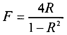
- As the laser wavelength A is scanned by Δλ from its nominal wavelength λc, the optical transmission T will follow a periodical pattern, the phase of which will depend on the total etalon length L, according to

where it is assumed that Δλ << λc. - If the etalon length L is changed exactly by ΔL = m·λ/4, where m is an odd number, the etalon fringe pattern will be reversed as shown in
Figure 2 . Thus, by changing the etalon length L back and forth in a certain manner at given frequency and amplitude, the unwanted periodic fringe pattern can be averaged out yielding flat optical transmission. - According to the invention and as can be seen in
Figure 1 , the optical path length of the etalon, here the etalon length L, is varied with a Gaussian distribution. For this purpose, a piezoelectric actuator 8 is coupled to one of theplanes plane 6, which actuator 8 is driven by aGaussian noise generator 9. - To vary the optical length L of the passive cavity (etalon), one of the optical surfaces of the
optical system 3 may be moved or tilted back and forth or a tunable optical element may be placed in said passive cavity to increase the optical path length by an additional length wherein said optical element is tuned as to vary the additional length with said Gaussian distribution. The tunable optical element may be an additional etalon, the thickness of which or the index of the medium therein are varied by means of an electrodynamic, magnetostrictive, electrostatic or piezoelectric actuator, or by means of pressure or sound or the like imposed on the medium inside the etalon. At least some of these measures are known as such and therefore need not be further explained here. -
Figure 3 shows the interference fringe amplitude F (peak-to-peak optical fringe depth) as a function of the variation amplitude in case of the Gaussian noise modulation according to the invention (solid line) and, for comparison, the triangle modulation according to the prior art (dashed line). As can be clearly seen, the advantage of the random modulation compared to the triangle modulation is that it is no longer necessary to use vibration amplitudes ΔL over several laser wavelengths λsince an efficient etalon averaging is obtained already at amplitude distribution with a standard deviation σ slightly above λ/4. Another advantage is that, due to character of noise modulation, there is no need of amplitude and phase control of the modulating waveform, thus allowing much simpler hardware design. - For comparison,
Figure 4 shows the interference fringe amplitude F/2 as a function of the variation amplitude in case of triangle modulation (solid line) and sinusoidal modulation (dashed line). Triangular waveform offers better etalon fringe reduction compared to sinus waveforms since the time spent by the vibrating element at the turning points is minimized. However, the vibration amplitude ΔL has to be more than 15 laser wavelengths λ to obtain a sufficient reduction of the etalon effect.
Claims (10)
- A method for reducing fringe interference of light created in a passive cavity defined by partially reflecting optical surfaces (6, 7), wherein the optical path length (L) of the cavity is varied with a Gaussian distribution, where the standard deviation is at least one-quarter of the light's wavelength.
- The method of claim 1, wherein the standard deviation is at least one-third wavelength.
- The method of claim 1 or 2, wherein the standard deviation is less than one wavelength.
- The method of any of claims 1 to 3, wherein along the optical path, the position of one of the optical surfaces (6, 7) of the passive cavity or, towards the optical path, the angle of one of the optical surfaces (6, 7) is varied with said Gaussian distribution.
- The method of any of claims 1 to 3, wherein an optical element is placed in said passive cavity to increase the optical path length by an additional length and wherein said optical element is tuned as to vary the additional length with said Gaussian distribution.
- An apparatus for reducing fringe interference of light created in a passive cavity defined by partially reflecting optical surfaces (6, 7), said apparatus comprising means (8, 9) for varying the optical path length (L) of the cavity with a Gaussian distribution, where the standard deviation is at least one-quarter of the light's wavelength.
- The apparatus of claim 6 wherein the standard deviation is at least one-third wavelength.
- The apparatus of claim 4 or 5 wherein the standard deviation is less than one wavelength.
- The apparatus of any of claims 6 to 8, wherein the means (8, 9) for varying the optical length of the cavity comprises an actuator (8) responsive to an electrical signal for varying, along the optical path, the position of one of the optical surfaces (6, 7) of the passive cavity or for varying the angle of one of the optical surfaces towards the optical path; and wherein the means (8, 9) for varying the optical length of the cavity further comprises a noise generator (9) connected to said actuator (8) and generating a Gaussian noise signal as said electrical signal.
- The apparatus of any of claims 6 to 8, wherein the means for varying the optical length of the cavity comprises an optical element arranged in said passive cavity to increase the optical path length by an additional length and wherein said optical element is tunable as to vary the additional length with said Gaussian distribution.
Priority Applications (3)
| Application Number | Priority Date | Filing Date | Title |
|---|---|---|---|
| DE602006014011T DE602006014011D1 (en) | 2006-11-30 | 2006-11-30 | Method of reducing light interference fringes |
| EP06024845A EP1927831B1 (en) | 2006-11-30 | 2006-11-30 | Method for reducing fringe interference of light |
| US11/998,479 US7800764B2 (en) | 2006-11-30 | 2007-11-30 | Method and apparatus for reducing fringe interference of light |
Applications Claiming Priority (1)
| Application Number | Priority Date | Filing Date | Title |
|---|---|---|---|
| EP06024845A EP1927831B1 (en) | 2006-11-30 | 2006-11-30 | Method for reducing fringe interference of light |
Publications (2)
| Publication Number | Publication Date |
|---|---|
| EP1927831A1 true EP1927831A1 (en) | 2008-06-04 |
| EP1927831B1 EP1927831B1 (en) | 2010-04-28 |
Family
ID=37983371
Family Applications (1)
| Application Number | Title | Priority Date | Filing Date |
|---|---|---|---|
| EP06024845A Active EP1927831B1 (en) | 2006-11-30 | 2006-11-30 | Method for reducing fringe interference of light |
Country Status (3)
| Country | Link |
|---|---|
| US (1) | US7800764B2 (en) |
| EP (1) | EP1927831B1 (en) |
| DE (1) | DE602006014011D1 (en) |
Cited By (11)
| Publication number | Priority date | Publication date | Assignee | Title |
|---|---|---|---|---|
| EP2136190A1 (en) | 2008-06-20 | 2009-12-23 | Siemens Aktiengesellschaft | Method for reducing fringe interference of light |
| EP2336738A1 (en) | 2009-12-17 | 2011-06-22 | Siemens Aktiengesellschaft | Apparatus for reducing fringe interference of light created in the optical system of a laser spectroscopy system |
| ITPD20100203A1 (en) * | 2010-06-28 | 2011-12-29 | L Pro S R L | EQUIPMENT FOR MEASURING A GAS CONCENTRATION IN A CLOSED CONTAINER |
| WO2013034482A1 (en) | 2011-09-09 | 2013-03-14 | Siemens Aktiengesellschaft | Laser spectrometer |
| DE102013218771B3 (en) * | 2013-09-19 | 2014-09-18 | Siemens Aktiengesellschaft | Method and gas analyzer for measuring the concentration of a gas component in a sample gas |
| EP2857812A1 (en) | 2013-10-02 | 2015-04-08 | Siemens Aktiengesellschaft | Method for measuring the concentration of a gas component in a gas to be measured |
| EP2899533A1 (en) | 2014-01-22 | 2015-07-29 | Siemens Aktiengesellschaft | Wavelength modulation spectroscopy method with a filter for the demodulated measurement signal and the simulated signal |
| EP3054280A1 (en) * | 2015-02-04 | 2016-08-10 | Axetris AG | Optical measuring device and method for gas detection |
| EP3163292A1 (en) * | 2015-10-26 | 2017-05-03 | ABB Schweiz AG | Laserspektrometer und verfahren zum betrieb eines laserspektrometers |
| EP3211389A1 (en) | 2016-02-29 | 2017-08-30 | Siemens Aktiengesellschaft | In-situ laser spectrometer |
| US11002673B2 (en) | 2016-11-04 | 2021-05-11 | Wilco Ag | Method for measuring a concentration of a gas |
Families Citing this family (4)
| Publication number | Priority date | Publication date | Assignee | Title |
|---|---|---|---|---|
| US9335257B2 (en) | 2013-06-20 | 2016-05-10 | Rosemount Analytical Inc. | Tunable diode laser absorption spectroscopy with water vapor determination |
| US9746375B2 (en) * | 2014-04-08 | 2017-08-29 | Yokogawa Electric Corporation | Systems, methods, and apparatus for optical noise management in optical spectroscopy |
| US10082457B2 (en) | 2015-11-19 | 2018-09-25 | International Business Machines Corporation | Ensuring stable, precise, and accurate optical absorption spectroscopic trace gas concentration measurements in the presence of time-varying etalons |
| JP7081146B2 (en) | 2017-12-27 | 2022-06-07 | 富士電機株式会社 | Gas analyzer |
Citations (3)
| Publication number | Priority date | Publication date | Assignee | Title |
|---|---|---|---|---|
| US4684258A (en) | 1985-07-31 | 1987-08-04 | The United States Of America As Represented By The Administrator Of The National Aeronautics And Space Administration | Method and apparatus for enhancing laser absorption sensitivity |
| US4934816A (en) | 1988-05-18 | 1990-06-19 | Southwest Sciences, Incorporated | Laser absorption detection enhancing apparatus and method |
| US5267019A (en) * | 1991-09-30 | 1993-11-30 | Consortium For Surface Processing, Inc. | Method and apparatus for reducing fringe interference in laser spectroscopy |
Family Cites Families (3)
| Publication number | Priority date | Publication date | Assignee | Title |
|---|---|---|---|---|
| US3809457A (en) * | 1972-10-13 | 1974-05-07 | Eastman Kodak Co | Radiation-redistributive devices |
| US6373632B1 (en) * | 2000-03-03 | 2002-04-16 | Axsun Technologies, Inc. | Tunable Fabry-Perot filter |
| US6628407B2 (en) * | 2000-12-22 | 2003-09-30 | Axsun Technologies, Inc. | System and process for side mode suppression by tunable filter train alignment in fiber optic system |
-
2006
- 2006-11-30 EP EP06024845A patent/EP1927831B1/en active Active
- 2006-11-30 DE DE602006014011T patent/DE602006014011D1/en active Active
-
2007
- 2007-11-30 US US11/998,479 patent/US7800764B2/en active Active
Patent Citations (3)
| Publication number | Priority date | Publication date | Assignee | Title |
|---|---|---|---|---|
| US4684258A (en) | 1985-07-31 | 1987-08-04 | The United States Of America As Represented By The Administrator Of The National Aeronautics And Space Administration | Method and apparatus for enhancing laser absorption sensitivity |
| US4934816A (en) | 1988-05-18 | 1990-06-19 | Southwest Sciences, Incorporated | Laser absorption detection enhancing apparatus and method |
| US5267019A (en) * | 1991-09-30 | 1993-11-30 | Consortium For Surface Processing, Inc. | Method and apparatus for reducing fringe interference in laser spectroscopy |
Non-Patent Citations (1)
| Title |
|---|
| LIANG-GUO WANG ET AL: "HIGH-SENSITIVITY FREQUENCY-MODULATION SPECTROSCOPY WITH A GAALAS DIODE LASER", JOURNAL OF THE OPTICAL SOCIETY OF AMERICA - B, OPTICAL SOCIETY OF AMERICA, WASHINGTON, US, vol. 6, no. 5, 1 May 1989 (1989-05-01), pages 871 - 876, XP000010015, ISSN: 0740-3224 * |
Cited By (18)
| Publication number | Priority date | Publication date | Assignee | Title |
|---|---|---|---|---|
| US8654339B2 (en) | 2008-06-20 | 2014-02-18 | Siemens Aktiengesellschaft | Method for reducing interference fringes by moving timing of triangular motion |
| EP2136190A1 (en) | 2008-06-20 | 2009-12-23 | Siemens Aktiengesellschaft | Method for reducing fringe interference of light |
| CN102128681B (en) * | 2009-12-17 | 2015-04-29 | 西门子公司 | Apparatus for reducing fringe interference of light created in the optical system of a laser spectroscopy system |
| EP2336738A1 (en) | 2009-12-17 | 2011-06-22 | Siemens Aktiengesellschaft | Apparatus for reducing fringe interference of light created in the optical system of a laser spectroscopy system |
| CN102128681A (en) * | 2009-12-17 | 2011-07-20 | 西门子公司 | Apparatus for reducing fringe interference of light created in the optical system of a laser spectroscopy system |
| US8619364B2 (en) | 2009-12-17 | 2013-12-31 | Siemens Aktiengesellschaft | Apparatus for reducing fringe interference of light created in an optical system of a laser spectroscopy system |
| ITPD20100203A1 (en) * | 2010-06-28 | 2011-12-29 | L Pro S R L | EQUIPMENT FOR MEASURING A GAS CONCENTRATION IN A CLOSED CONTAINER |
| WO2012001633A3 (en) * | 2010-06-28 | 2014-02-13 | L Pro S.R.L. | Apparatus for the measurement of the gas concentration in a sealed container |
| WO2013034482A1 (en) | 2011-09-09 | 2013-03-14 | Siemens Aktiengesellschaft | Laser spectrometer |
| DE102013218771B3 (en) * | 2013-09-19 | 2014-09-18 | Siemens Aktiengesellschaft | Method and gas analyzer for measuring the concentration of a gas component in a sample gas |
| EP2857812A1 (en) | 2013-10-02 | 2015-04-08 | Siemens Aktiengesellschaft | Method for measuring the concentration of a gas component in a gas to be measured |
| EP2899533A1 (en) | 2014-01-22 | 2015-07-29 | Siemens Aktiengesellschaft | Wavelength modulation spectroscopy method with a filter for the demodulated measurement signal and the simulated signal |
| US9709487B2 (en) | 2014-01-22 | 2017-07-18 | Siemens Aktiengesellschaft | Method for measuring the concentration of a gas component in a measuring gas |
| EP3054280A1 (en) * | 2015-02-04 | 2016-08-10 | Axetris AG | Optical measuring device and method for gas detection |
| EP3163292A1 (en) * | 2015-10-26 | 2017-05-03 | ABB Schweiz AG | Laserspektrometer und verfahren zum betrieb eines laserspektrometers |
| EP3211389A1 (en) | 2016-02-29 | 2017-08-30 | Siemens Aktiengesellschaft | In-situ laser spectrometer |
| US11002673B2 (en) | 2016-11-04 | 2021-05-11 | Wilco Ag | Method for measuring a concentration of a gas |
| EP3535563B1 (en) * | 2016-11-04 | 2023-06-07 | Wilco AG | Method and apparatus for measuring a concentration of a gas |
Also Published As
| Publication number | Publication date |
|---|---|
| US20080137084A1 (en) | 2008-06-12 |
| DE602006014011D1 (en) | 2010-06-10 |
| EP1927831B1 (en) | 2010-04-28 |
| US7800764B2 (en) | 2010-09-21 |
Similar Documents
| Publication | Publication Date | Title |
|---|---|---|
| EP1927831B1 (en) | Method for reducing fringe interference of light | |
| US11409184B2 (en) | Acousto-optic deflector with multiple output beams | |
| Von der Linde | Characterization of the noise in continuously operating mode-locked lasers | |
| US5956355A (en) | Method and apparatus for performing optical measurements using a rapidly frequency-tuned laser | |
| US7433043B2 (en) | Two-dimensional spectral shearing interferometry for ultrafast pulse characterization | |
| EP2336738B1 (en) | Apparatus for reducing fringe interference of light created in the optical system of a laser spectroscopy system | |
| US7197208B2 (en) | Wavelength tunable light sources and methods of operating the same | |
| EP1635433A2 (en) | Frequency tunable light sources and methods of generating frequency-tunable light | |
| KR101447392B1 (en) | Apparatus and method for measuring metal structure and material | |
| WO2017119389A1 (en) | Fourier transform-type spectroscopic device | |
| US8654339B2 (en) | Method for reducing interference fringes by moving timing of triangular motion | |
| JP3533651B1 (en) | Time-resolved nonlinear susceptibility measurement system | |
| EP2166324B1 (en) | System and method for suppressing noise by frequency dither | |
| Doughty et al. | Considerations in upconversion: A practical guide to sum-frequency generation spectrometer design and implementation | |
| KR102534878B1 (en) | Terahertz device | |
| Ovchinnikov et al. | Revivals and oscillations of the momentum of light in a planar multimode waveguide | |
| Jing-Zhou et al. | Spatial and temporal evolution of ultra-wide-band optical pulses in propagation | |
| Seshadri et al. | Ultrafast dynamic beam steering with optical frequency comb arrays | |
| US11656268B2 (en) | Apparatus and method for testing coupled AC circuit | |
| Riza et al. | Submicrosecond speed optical coherence tomography system design and analysis using acousto-optics | |
| JP2022172920A (en) | Measurement device | |
| Knuuttila et al. | High resolution laser-interferometric probing of SAW devices | |
| Xiao et al. | Spatial chirp effects in virtually-imaged phased-array wavelength demultiplexors |
Legal Events
| Date | Code | Title | Description |
|---|---|---|---|
| PUAI | Public reference made under article 153(3) epc to a published international application that has entered the european phase |
Free format text: ORIGINAL CODE: 0009012 |
|
| AK | Designated contracting states |
Kind code of ref document: A1 Designated state(s): AT BE BG CH CY CZ DE DK EE ES FI FR GB GR HU IE IS IT LI LT LU LV MC NL PL PT RO SE SI SK TR |
|
| AX | Request for extension of the european patent |
Extension state: AL BA HR MK RS |
|
| 17P | Request for examination filed |
Effective date: 20081022 |
|
| 17Q | First examination report despatched |
Effective date: 20081124 |
|
| AKX | Designation fees paid |
Designated state(s): DE FR GB |
|
| GRAP | Despatch of communication of intention to grant a patent |
Free format text: ORIGINAL CODE: EPIDOSNIGR1 |
|
| RTI1 | Title (correction) |
Free format text: METHOD FOR REDUCING FRINGE INTERFERENCE OF LIGHT |
|
| GRAS | Grant fee paid |
Free format text: ORIGINAL CODE: EPIDOSNIGR3 |
|
| GRAA | (expected) grant |
Free format text: ORIGINAL CODE: 0009210 |
|
| AK | Designated contracting states |
Kind code of ref document: B1 Designated state(s): DE FR GB |
|
| REG | Reference to a national code |
Ref country code: GB Ref legal event code: FG4D |
|
| REF | Corresponds to: |
Ref document number: 602006014011 Country of ref document: DE Date of ref document: 20100610 Kind code of ref document: P |
|
| PLBE | No opposition filed within time limit |
Free format text: ORIGINAL CODE: 0009261 |
|
| STAA | Information on the status of an ep patent application or granted ep patent |
Free format text: STATUS: NO OPPOSITION FILED WITHIN TIME LIMIT |
|
| 26N | No opposition filed |
Effective date: 20110131 |
|
| REG | Reference to a national code |
Ref country code: FR Ref legal event code: PLFP Year of fee payment: 10 |
|
| REG | Reference to a national code |
Ref country code: FR Ref legal event code: PLFP Year of fee payment: 11 |
|
| REG | Reference to a national code |
Ref country code: FR Ref legal event code: PLFP Year of fee payment: 12 |
|
| PGFP | Annual fee paid to national office [announced via postgrant information from national office to epo] |
Ref country code: DE Payment date: 20230119 Year of fee payment: 17 |
|
| PGFP | Annual fee paid to national office [announced via postgrant information from national office to epo] |
Ref country code: GB Payment date: 20231204 Year of fee payment: 18 |
|
| PGFP | Annual fee paid to national office [announced via postgrant information from national office to epo] |
Ref country code: FR Payment date: 20231114 Year of fee payment: 18 |