EP3535556B1 - Combustion pressure sensor and its assembly in an engine component of an internal combustion engine - Google Patents
Combustion pressure sensor and its assembly in an engine component of an internal combustion engine Download PDFInfo
- Publication number
- EP3535556B1 EP3535556B1 EP17822797.1A EP17822797A EP3535556B1 EP 3535556 B1 EP3535556 B1 EP 3535556B1 EP 17822797 A EP17822797 A EP 17822797A EP 3535556 B1 EP3535556 B1 EP 3535556B1
- Authority
- EP
- European Patent Office
- Prior art keywords
- temperature
- combustion
- optical fibre
- membrane
- cylinder
- Prior art date
- Legal status (The legal status is an assumption and is not a legal conclusion. Google has not performed a legal analysis and makes no representation as to the accuracy of the status listed.)
- Active
Links
Images


Classifications
-
- G—PHYSICS
- G01—MEASURING; TESTING
- G01M—TESTING STATIC OR DYNAMIC BALANCE OF MACHINES OR STRUCTURES; TESTING OF STRUCTURES OR APPARATUS, NOT OTHERWISE PROVIDED FOR
- G01M15/00—Testing of engines
- G01M15/04—Testing internal-combustion engines
- G01M15/08—Testing internal-combustion engines by monitoring pressure in cylinders
-
- F—MECHANICAL ENGINEERING; LIGHTING; HEATING; WEAPONS; BLASTING
- F02—COMBUSTION ENGINES; HOT-GAS OR COMBUSTION-PRODUCT ENGINE PLANTS
- F02B—INTERNAL-COMBUSTION PISTON ENGINES; COMBUSTION ENGINES IN GENERAL
- F02B77/00—Component parts, details or accessories, not otherwise provided for
- F02B77/08—Safety, indicating, or supervising devices
- F02B77/085—Safety, indicating, or supervising devices with sensors measuring combustion processes, e.g. knocking, pressure, ionization, combustion flame
-
- F—MECHANICAL ENGINEERING; LIGHTING; HEATING; WEAPONS; BLASTING
- F02—COMBUSTION ENGINES; HOT-GAS OR COMBUSTION-PRODUCT ENGINE PLANTS
- F02D—CONTROLLING COMBUSTION ENGINES
- F02D35/00—Controlling engines, dependent on conditions exterior or interior to engines, not otherwise provided for
- F02D35/0007—Controlling engines, dependent on conditions exterior or interior to engines, not otherwise provided for using electrical feedback
-
- F—MECHANICAL ENGINEERING; LIGHTING; HEATING; WEAPONS; BLASTING
- F02—COMBUSTION ENGINES; HOT-GAS OR COMBUSTION-PRODUCT ENGINE PLANTS
- F02D—CONTROLLING COMBUSTION ENGINES
- F02D35/00—Controlling engines, dependent on conditions exterior or interior to engines, not otherwise provided for
- F02D35/02—Controlling engines, dependent on conditions exterior or interior to engines, not otherwise provided for on interior conditions
- F02D35/022—Controlling engines, dependent on conditions exterior or interior to engines, not otherwise provided for on interior conditions using an optical sensor, e.g. in-cylinder light probe
-
- F—MECHANICAL ENGINEERING; LIGHTING; HEATING; WEAPONS; BLASTING
- F02—COMBUSTION ENGINES; HOT-GAS OR COMBUSTION-PRODUCT ENGINE PLANTS
- F02D—CONTROLLING COMBUSTION ENGINES
- F02D35/00—Controlling engines, dependent on conditions exterior or interior to engines, not otherwise provided for
- F02D35/02—Controlling engines, dependent on conditions exterior or interior to engines, not otherwise provided for on interior conditions
- F02D35/023—Controlling engines, dependent on conditions exterior or interior to engines, not otherwise provided for on interior conditions by determining the cylinder pressure
-
- F—MECHANICAL ENGINEERING; LIGHTING; HEATING; WEAPONS; BLASTING
- F02—COMBUSTION ENGINES; HOT-GAS OR COMBUSTION-PRODUCT ENGINE PLANTS
- F02D—CONTROLLING COMBUSTION ENGINES
- F02D35/00—Controlling engines, dependent on conditions exterior or interior to engines, not otherwise provided for
- F02D35/02—Controlling engines, dependent on conditions exterior or interior to engines, not otherwise provided for on interior conditions
- F02D35/025—Controlling engines, dependent on conditions exterior or interior to engines, not otherwise provided for on interior conditions by determining temperatures inside the cylinder, e.g. combustion temperatures
-
- F—MECHANICAL ENGINEERING; LIGHTING; HEATING; WEAPONS; BLASTING
- F02—COMBUSTION ENGINES; HOT-GAS OR COMBUSTION-PRODUCT ENGINE PLANTS
- F02D—CONTROLLING COMBUSTION ENGINES
- F02D35/00—Controlling engines, dependent on conditions exterior or interior to engines, not otherwise provided for
- F02D35/02—Controlling engines, dependent on conditions exterior or interior to engines, not otherwise provided for on interior conditions
- F02D35/028—Controlling engines, dependent on conditions exterior or interior to engines, not otherwise provided for on interior conditions by determining the combustion timing or phasing
-
- F—MECHANICAL ENGINEERING; LIGHTING; HEATING; WEAPONS; BLASTING
- F02—COMBUSTION ENGINES; HOT-GAS OR COMBUSTION-PRODUCT ENGINE PLANTS
- F02D—CONTROLLING COMBUSTION ENGINES
- F02D41/00—Electrical control of supply of combustible mixture or its constituents
- F02D41/02—Circuit arrangements for generating control signals
- F02D41/14—Introducing closed-loop corrections
- F02D41/1438—Introducing closed-loop corrections using means for determining characteristics of the combustion gases; Sensors therefor
- F02D41/1439—Introducing closed-loop corrections using means for determining characteristics of the combustion gases; Sensors therefor characterised by the position of the sensor
-
- F—MECHANICAL ENGINEERING; LIGHTING; HEATING; WEAPONS; BLASTING
- F02—COMBUSTION ENGINES; HOT-GAS OR COMBUSTION-PRODUCT ENGINE PLANTS
- F02D—CONTROLLING COMBUSTION ENGINES
- F02D41/00—Electrical control of supply of combustible mixture or its constituents
- F02D41/02—Circuit arrangements for generating control signals
- F02D41/14—Introducing closed-loop corrections
- F02D41/1438—Introducing closed-loop corrections using means for determining characteristics of the combustion gases; Sensors therefor
- F02D41/1444—Introducing closed-loop corrections using means for determining characteristics of the combustion gases; Sensors therefor characterised by the characteristics of the combustion gases
- F02D41/1451—Introducing closed-loop corrections using means for determining characteristics of the combustion gases; Sensors therefor characterised by the characteristics of the combustion gases the sensor being an optical sensor
-
- F—MECHANICAL ENGINEERING; LIGHTING; HEATING; WEAPONS; BLASTING
- F02—COMBUSTION ENGINES; HOT-GAS OR COMBUSTION-PRODUCT ENGINE PLANTS
- F02D—CONTROLLING COMBUSTION ENGINES
- F02D41/00—Electrical control of supply of combustible mixture or its constituents
- F02D41/02—Circuit arrangements for generating control signals
- F02D41/14—Introducing closed-loop corrections
- F02D41/1438—Introducing closed-loop corrections using means for determining characteristics of the combustion gases; Sensors therefor
- F02D41/1473—Introducing closed-loop corrections using means for determining characteristics of the combustion gases; Sensors therefor characterised by the regulation method
- F02D41/1475—Regulating the air fuel ratio at a value other than stoichiometry
-
- F—MECHANICAL ENGINEERING; LIGHTING; HEATING; WEAPONS; BLASTING
- F02—COMBUSTION ENGINES; HOT-GAS OR COMBUSTION-PRODUCT ENGINE PLANTS
- F02D—CONTROLLING COMBUSTION ENGINES
- F02D41/00—Electrical control of supply of combustible mixture or its constituents
- F02D41/30—Controlling fuel injection
- F02D41/38—Controlling fuel injection of the high pressure type
- F02D41/40—Controlling fuel injection of the high pressure type with means for controlling injection timing or duration
- F02D41/402—Multiple injections
-
- F—MECHANICAL ENGINEERING; LIGHTING; HEATING; WEAPONS; BLASTING
- F02—COMBUSTION ENGINES; HOT-GAS OR COMBUSTION-PRODUCT ENGINE PLANTS
- F02M—SUPPLYING COMBUSTION ENGINES IN GENERAL WITH COMBUSTIBLE MIXTURES OR CONSTITUENTS THEREOF
- F02M57/00—Fuel-injectors combined or associated with other devices
- F02M57/005—Fuel-injectors combined or associated with other devices the devices being sensors
-
- F—MECHANICAL ENGINEERING; LIGHTING; HEATING; WEAPONS; BLASTING
- F02—COMBUSTION ENGINES; HOT-GAS OR COMBUSTION-PRODUCT ENGINE PLANTS
- F02P—IGNITION, OTHER THAN COMPRESSION IGNITION, FOR INTERNAL-COMBUSTION ENGINES; TESTING OF IGNITION TIMING IN COMPRESSION-IGNITION ENGINES
- F02P5/00—Advancing or retarding ignition; Control therefor
- F02P5/04—Advancing or retarding ignition; Control therefor automatically, as a function of the working conditions of the engine or vehicle or of the atmospheric conditions
- F02P5/045—Advancing or retarding ignition; Control therefor automatically, as a function of the working conditions of the engine or vehicle or of the atmospheric conditions combined with electronic control of other engine functions, e.g. fuel injection
-
- F—MECHANICAL ENGINEERING; LIGHTING; HEATING; WEAPONS; BLASTING
- F02—COMBUSTION ENGINES; HOT-GAS OR COMBUSTION-PRODUCT ENGINE PLANTS
- F02P—IGNITION, OTHER THAN COMPRESSION IGNITION, FOR INTERNAL-COMBUSTION ENGINES; TESTING OF IGNITION TIMING IN COMPRESSION-IGNITION ENGINES
- F02P5/00—Advancing or retarding ignition; Control therefor
- F02P5/04—Advancing or retarding ignition; Control therefor automatically, as a function of the working conditions of the engine or vehicle or of the atmospheric conditions
- F02P5/145—Advancing or retarding ignition; Control therefor automatically, as a function of the working conditions of the engine or vehicle or of the atmospheric conditions using electrical means
-
- F—MECHANICAL ENGINEERING; LIGHTING; HEATING; WEAPONS; BLASTING
- F02—COMBUSTION ENGINES; HOT-GAS OR COMBUSTION-PRODUCT ENGINE PLANTS
- F02P—IGNITION, OTHER THAN COMPRESSION IGNITION, FOR INTERNAL-COMBUSTION ENGINES; TESTING OF IGNITION TIMING IN COMPRESSION-IGNITION ENGINES
- F02P5/00—Advancing or retarding ignition; Control therefor
- F02P5/04—Advancing or retarding ignition; Control therefor automatically, as a function of the working conditions of the engine or vehicle or of the atmospheric conditions
- F02P5/145—Advancing or retarding ignition; Control therefor automatically, as a function of the working conditions of the engine or vehicle or of the atmospheric conditions using electrical means
- F02P5/15—Digital data processing
- F02P5/153—Digital data processing dependent on combustion pressure
-
- G—PHYSICS
- G01—MEASURING; TESTING
- G01L—MEASURING FORCE, STRESS, TORQUE, WORK, MECHANICAL POWER, MECHANICAL EFFICIENCY, OR FLUID PRESSURE
- G01L11/00—Measuring steady or quasi-steady pressure of a fluid or a fluent solid material by means not provided for in group G01L7/00 or G01L9/00
- G01L11/02—Measuring steady or quasi-steady pressure of a fluid or a fluent solid material by means not provided for in group G01L7/00 or G01L9/00 by optical means
- G01L11/025—Measuring steady or quasi-steady pressure of a fluid or a fluent solid material by means not provided for in group G01L7/00 or G01L9/00 by optical means using a pressure-sensitive optical fibre
-
- G—PHYSICS
- G01—MEASURING; TESTING
- G01L—MEASURING FORCE, STRESS, TORQUE, WORK, MECHANICAL POWER, MECHANICAL EFFICIENCY, OR FLUID PRESSURE
- G01L23/00—Devices or apparatus for measuring or indicating or recording rapid changes, such as oscillations, in the pressure of steam, gas, or liquid; Indicators for determining work or energy of steam, internal-combustion, or other fluid-pressure engines from the condition of the working fluid
- G01L23/06—Indicating or recording by optical means
-
- G—PHYSICS
- G01—MEASURING; TESTING
- G01L—MEASURING FORCE, STRESS, TORQUE, WORK, MECHANICAL POWER, MECHANICAL EFFICIENCY, OR FLUID PRESSURE
- G01L9/00—Measuring steady of quasi-steady pressure of fluid or fluent solid material by electric or magnetic pressure-sensitive elements; Transmitting or indicating the displacement of mechanical pressure-sensitive elements, used to measure the steady or quasi-steady pressure of a fluid or fluent solid material, by electric or magnetic means
- G01L9/0041—Transmitting or indicating the displacement of flexible diaphragms
- G01L9/0076—Transmitting or indicating the displacement of flexible diaphragms using photoelectric means
- G01L9/0077—Transmitting or indicating the displacement of flexible diaphragms using photoelectric means for measuring reflected light
Definitions
- the invention relates to an improved combustion pressure sensor using optical fibre technology, and being in particular adapted to detect the combustion pressure in an internal combustion engine.
- the invention also relates to a combustion engine equipped with the improved combustion sensor.
- Combustion pressure sensors enable to achieve excellent engine control with a minimum of sensors.
- the combustion pressure sensor can provide information about the combustion directly from the combustion chamber. Such information includes effects of ignition timing, of valve timing, and supply of energy, but would also enable detection of engine damage hazards, like auto-ignition, engine knock, blow-by, exceeding of maximum combustion pressure (P max ) or exceeding of too much pressure rise per crank angle D p /da.
- P max maximum combustion pressure
- combustion pressure sensors such as those available from Optrand and described in US 6,131,465 can however only withstand a limited working temperature at the risk of the fixation or connection between their optical fibre and the body of the sensor becoming damaged.
- the maximum temperature allowed by the glass bond is at best 510 °C or lower, which requires a sensor tip temperature not to exceed a temperature of 510 °C.
- the prevention of soot fouling of the sensor tip would require a temperature of at least 535 °C, while in practice the sensor tip could well become exposed to combustion temperatures of up to 800 °C.
- Another disadvantage of the known combustion pressure sensors is their sensitivity to temperature variations, known as thermo-shock. This sensitivity to temperature changes distorts the pressure measurements in a rather unpredictable manner.
- a still further disadvantage of the known combustion pressure sensors is their insufficient resistance to engine knock, knock results in a raise of temperature with an easy 10.000°C.
- the known combustion pressure sensors have only seen limited use in engine research, and on test bed engines but not successfully in the field unfortunately.
- combustion pressure sensor that are sufficiently small, e.g. 2.5 mm in diameter, to be build in into engine components, e.g. injectors or glowplugs, are not proven to be suitable for continuous usage.
- some type combustion pressure sensors had to be equipped with a liquid cooling system. No such sensors have yet proven suitable for continuous use on commercially produced internal combustion engines as part of an engine management system.
- US 5,146,083A fibre optic microphone for measuring fluctuating pressures.
- An optical fibre probe having at least one transmitting fibre for transmitting light to a pressure-sensing membrane and at least one receiving fibre for receiving light reflected from a stretched membrane is provided.
- the microphone comprises one centrally located transmitting fibre and six surrounding receiving fibres.
- a combustion pressure sensor in accordance with the invention can comprise a sensor body, at least one first optical fibre inserted into the sensor body, and a resiliently deformable membrane attached to the sensor body, the membrane having a reflective surface, wherein the at least one first optical fibre is arranged for allowing measuring of a pressure induced deflection of the resiliently deformable membrane, wherein an end of the at least one first optical fibre module is connected to the sensor body to guide a light beam to the reflective surface and to guide the reflected light, at least one second optical fibre module is inserted into the sensor body to guide a light beam to the reflective surface and to guide the reflected light, the at least one second optical fibre module is arranged for allowing detection of a temperature induced thermal expansion of the resiliently deformable membrane to enable temperature correction of pressure related values obtained by the at least one first optical fibre module, the first optical fibre module is positioned centrally with respect to the resiliently deformable membrane; and the second optical fibre module is positioned adjacent to an outer edge of the resiliently deformable membrane.
- the at least one first optical fibre “set” can be arranged for allowing measuring of a pressure induced deflection of the resiliently deformable membrane, and an end of the at least one second “set” optical fibres can be connected to the sensor body in a manner that withstands temperatures within a temperature range hot enough to regenerate soot depositions on the resiliently deformable membrane, yet cool enough to prevent melting of the resiliently deformable membrane.
- the temperature range of such a combustion pressure sensor can be between 540 °C and 750 °C.
- the sensor body can optionally be made of a material having a relatively low expansion coefficient lower than ⁇ 6 (*10-6m/m K-1). In order to expand minimum in relation to the fibre that is made from Quartz, the body therefore could be made from Kovar (low Coefficient of Thermal Expansion "CTE" Stainless Steel), Quartz or Ceramic material.
- the at least one first optical fibre can be connected to the sensor body by either Soldering or Brazing, by using for example a vacuum furnace or non vacuum and induction and or Handy Hi Temp Flux, and Vacuum Brazing Paste HF350/60-521/90Bl which can both be delivered by www.lucasmilhaupt.com, bonding, cementing like Ceramabond that can be delivered by www.aremco.com, or press fitting.
- the manner of connecting the at least one first optical fibre to the sensor body can be effective to resist disconnection under temperature induced expansion and contraction.
- the end of the at least one first optical fibre can be connected to the sensor body by at least one ferrule.
- the end of the at least one first optical fibre can also be connected to the sensor body by a pair of ferrules oppositely engaging a portion of the sensor body.
- the at least one ferrule can be made of a material having a relatively low expansion coefficient, including either quartz or ceramic.
- the end of the at least one first optical fibre can also be connected to the sensor body by a cutting ring, which is arranged to cut only in a fibre coating, and not in the fibre itself.
- Either one of the optional connections of the end of the at least one first optical fibre to the sensor body can also be combined with the connection being arranged to put the connected end under tension, which can be accomplished by a spring.
- combustion pressure sensor can be placed cold enough than optionally a polyamide coated fiber can be connected to the ferule or body by for example polyamide injection moulding.
- At least one second optical fibre can be inserted into the sensor body, and then the at least one second optical fibre can be arranged for allowing detection of a temperature induced thermal expansion of the resiliently deformable membrane to enable temperature correction of pressure related values obtained by the at least one first optical fibre.
- the at least one first optical fibre can be positioned centrally with respect to the resiliently deformable membrane, while the at least one second optical fibre can be positioned adjacent to an outer edge of the resiliently deformable membrane.
- the at least one second optical fibre can be one of a second pair of optical fibres, while one optical fibre of the second pair emits light, and the other optical fibre of the second pair allows measuring of an intensity of light reflected by a reflective surface on the outer edge of the resiliently deformable membrane.
- the at least one first optical fibre can be one of a first pair of optical fibres, while one optical fibre of the first pair emits light, and the other optical fibre of the first pair allows measuring of an intensity of light reflected by a reflective surface on a central part of the resiliently deformable membrane.
- at least one end of each of the optical fibres comprised by the first pair is placed at a distance of the reflective surface to allow the reflected light to be reflected in one of the optical fibres.
- the at least one first optical fibre alternatively can be arranged for optical beam splitting.
- the optical beam splitting can then be obtained by a dialectic mirror in accordance with a Fabry-Pérot measuring principle, and cause a difference in paths of interference.
- the at least one first optical fibre can also be arranged for detection of changes of optical fibre length, by using a Fibre Brag Grating (FBG) measuring principle.
- FBG Fibre Brag Grating
- the at least one optical fibre comprises multiple segments / lenses of which at least one optical transmission factor is arranged to change as a result of changes in strain in the at least one first optical fibre.
- the optical transmission factor is in one embodiment of the at least one first optical fibre the refractive index.
- the refractive index is different for different wavelengths of light.
- the deformation of the flexible membrane at the point to which the at least one first optical fibre is attached can be determined.
- the other end of the at least one first optical fibre is attached at another point, such that the at least one first optical fibre length can only change due to deformation of the flexible membrane to which it is attached.
- An internal combustion engine in accordance with the invention can include at least one combustion pressure sensor with one or more of the above features.
- the at least one combustion pressure sensor can be positioned with its resiliently deformable membrane in direct contact with a surrounding body of an engine component for possibly direct transfer of heat to the surrounding body.
- the engine component can either be a fuel injection device or a cylinder head or any other engine part.
- the resiliently deformable membrane can be separated from a combustion chamber of the internal combustion engine by a channel in the engine component.
- a channel can have a length that is selected to commensurate with the working temperature range of the resiliently deformable membrane.
- a heat shield can be positioned within the channel at a location interposed between the combustion chamber and the resiliently deformable membrane.
- Another variation of the internal combustion engine of the invention can further include an engine management control system that is connected to the at least one combustion pressure sensor for governing operation of the engine in commercial use.
- an engine management control system that is connected to the at least one combustion pressure sensor for governing operation of the engine in commercial use.
- the engine management control system can then be adapted to calculate temperature correction of pressure related values obtained by the at least one first optical fibre.
- the engine management control system further comprises a first light source, arranged to provide a first light beam to the at least one first optical fibre. Also comprised by the engine management control system is a first light sensor, arranged to receive a reflected part of the first light beam.
- the engine management control system When provided with at least one second optical fibre, the engine management control system is arranged to determine a temperature difference between multiple locations of the resiliently deformable membrane.
- a second light source and a second light sensor are provided in the engine management control system.
- Another feature of the invention is the ability to measure, in real-time, the temperature in the cylinder. This information can be used to optimise temperature losses in the engine and therewith increase engine efficiency.
- the combustion pressure sensor of the invention can use the working principle of optical fibre technology to measure intensity of light reflected by a deformable membrane to record bending of the membrane caused by pressure variations.
- the temperature of the membrane is controlled by design of the sensor and its mounting in a surrounding engine component to be, in use, above a value of 540 °C to counteract / regenerate deposition of soot on the membrane, and below a maximum temperature value of 750 °C to prevent damage to the membrane.
- This working temperature range is made possible by a fixation of the optical fibre that can withstand these elevated temperatures.
- the combustion pressure sensor is optionally mounted with its membrane in direct contact with a surrounding engine component, rather than that the heat of the membrane has first to dissipate via the sensor body before reaching the engine component, this to shortcut the distance for dissipating the heat.
- An other way to shortcut the heat transfer from the membrane to the coolant of the engine is to introduce a airgap on the nose of the ferule in order to isolate the ferule and give enough material around it to transfer this heat.
- the temperature to which the membrane of the combustion pressure sensor becomes exposed is adapted to the required working range of temperatures. If the temperature of the membrane would get below a value of 540 °C it will become contaminated by soot and measurements will become inaccurate or become inhibited altogether. When during maximum power operation of the internal combustion engine the membrane of the combustion pressure sensor would get to its upper temperature limit, occurrence of detonation or engine knock could easily result in destruction of the membrane. It is therefore important that the temperature to which the membrane of the combustion pressure sensor is exposed does not exceed a maximum of 750 °C to remain sufficiently robust. Hence the benefit of an improved heat transfer cooperation between the sensor and the surrounding body, such as cylinder head or injector body in which it is mounted.
- This aspect thus also relates to the combination of the sensor and its surrounding body, and the features relating to temperature control also work together to enable continuous use of the sensor of the invention in conjunction with an engine management control unit. Additional cooling of the sensor may be obtained by locating it in proximity of cooling water passages or fuel delivery conduits. In air cooled combustion engines a location close to nearby cooling ribs can be selected.
- the surrounding body can be formed by different materials, such as aluminium or cast iron (cylinder heads), or steel (injector body or separate adapter).
- a separate adapter for mounting the combustion pressure sensor in an internal combustion engine can also include a spark plug or a glow plug.
- the membrane of the combustion pressure sensor can dissipate heat to its surrounding body as directly as possible.
- a heat shield can also be applied to reduce the heat to which the membrane is directly exposed.
- thermoshield lowers the thermos-shock. But the combustion pressure sensor does not need that because it takes away the thermos-shock. It does so by means of the second fibre "set" with the two fiber sets its possible to calculate the deflection coming from the heat change of the membrane and the deflection coming from the pressure on the membrane. This is done by the principle that you now have two equations with two unknowns and this is mathematically solvable.
- the big disadvantage of the heatshield is soot clogging problems that give the sensor a too short life ⁇ 3months to use in an application outside a engine laboratory. So the only reason to mention a heatshield is not to exclude the option to use one as a plan B for new upcoming situations in the future.
- Another aspect of the invention is related to fixation of the optical fibre to the sensor body, which is also sensitive to temperature.
- the temperature per cycle in a combustion chamber of an internal combustion engine can vary between 0 °C and 10,000 °C, depending on the type of engine. Even in the sheltered environment selected for the combustion pressure sensor this means that the connection of the optical fibres to the sensor body should also be able to follow quickly changing temperature extremes without endangering the bond between fibre and sensor body. This bond could be endangered when the bonding material disintegrates, or when the expansion coefficient of the optical fibre is greatly different from the material of the sensor body.
- the invention proposes a sensor body of a material having a relatively low expansion coefficient, such as quartz or ceramic material.
- the expansion coefficient is lower than ⁇ 6 (*10-6m/m K-1) to ensure that the optical fibres are robustly fixed in the sensor body.
- ferrules to fix the optical fibre with respect to the sensor body.
- ferrules also can be made of a material having a low expansion coefficient, such as quartz or ceramic material. Also soldering, brazing, gluing, injection moulding or even press fit connections may then be employed without risk of working loose as a result of changing temperatures.
- thermo-shock problem is solved by enabling membrane deformations caused by heat to be distinguished from membrane deformations caused by pressure.
- Conventional combustion pressure sensors show thermo-shock sensitivity of up to 30%, especially when a heatshield is not been used.
- the invention proposes to measure both the enlargement of the membrane caused mainly by a raise in temperature, as well as the bending of the membrane caused mainly by a change in pressure. The obtained measuring value can then be used to calculate the actual pressure value.
- An extra set of optical fibres can be used to measure the membrane enlargement or expansion caused by heat.
- optical fibre may solely be used to guide a light beam to a reflective surface of the sensor membrane, and another to guide the reflected light beam
- a single optical fibre to detect membrane deformation. This can be achieved by using optic beam splitting, or by using Piezo, Fabry-Pérot or Fibre Bragg Grating (FBG) measuring principles.
- FBG Fibre Bragg Grating
- the optical fibre or optical fibres can be attached to the sensor body by clamping. While fixation by brazing or soldering may initially be preferred because it is both robust and small, a variety of other fixation options may nonetheless be successfully employed.
- fixation by brazing or soldering may initially be preferred because it is both robust and small, a variety of other fixation options may nonetheless be successfully employed.
- One option is a cutting ring akin to those in use with pipe connections and fittings. It is also possible to tension the optical fibre between two ferrules, either by means of a spring or by bringing the optical fibre itself in a pre-tensioned state.
- the ferrules can be fixed to the optical fibre by soldering, by clamping, or by melting of the optical glass fibre. When a cutting ring is used, it is preferred that this only cuts into the coating of the optical fibre.
- Yet another aspect of the invention is to control the temperature of the combustion in at least one cylinder of an internal combustion engine as a combustion room during combustion. It is known that during combustion of a combustible in an internal combustion engine NO x may be formed and CH 4 (methane) may not be burned completely. It is an objective of this invention to optimize the temperature of combustion in the internal combustion engine to minimise emissions like NO x , , CH 4 or any other emission like CO and THC .
- a control module is used to control different engine parameters based on information provided by sensors provided at or in the cylinder.
- the information provided comprises at least one of a pressure inside the cylinder, an available volume in the cylinder for fuel and oxygen, a temperature in the cylinder, an amount of injected fuel, or any other engine parameter.
- the control module is arranged to calculate the theoretical combustion temperature out of pressure measured in the cylinder corrected for the real volume knowing the piston position it is also possible due to this invention to directly calculate the combustion temperature by the temperature value of the CPS membrane given by the CPS affect at least one of an air-to-fuel ratio (lambda), an ignition timing, an amount of fuel injected, and an amount of times fuel is injected for one combustion cycle.
- air is to be understood as a mixture of approximately one fifth of oxygen (O 2 ), four fifths of nitrogen (N 2 ) and small amounts of other gases.
- the pressure inside the cylinder can be obtained from the combustion pressure sensor, the volume can be derived from cylinder parameters such as a bore, a stroke, and a crank shaft angle.
- the constant k can be derived from a known air-to-fuel ratio and an amount of fuel injected in the cylinder.
- HCCI Homogeneous Charge Compression Ignition
- RCCI Reactive Controlled Compression Ignition
- HCCI Homogeneous Charge Compression Ignition
- RCCI Reactive Controlled Compression Ignition
- a first combustible is introduced in a cylinder along with a pre-determined amount of oxygen or air and optionally a pre-determined amount of recirculated exhaust gases.
- the first combustible is allowed to mix with the oxygen and optional exhaust gases.
- a second combustible is introduced in the cylinder, wherein the second combustible ignites at a lower pressure as the first combustible.
- Single or multiple injections of second combustible may be performed, and the second combustible is ignited due to a high pressure inside the cylinder.
- the combustion of the second combustible acts as a spark to ignite the first combustible.
- Another method of obtaining the temperature inside the cylinder is by comparing the deflection of the resilient membrane measured by at least one of the first fibre module and second fibre module. Values may be used to compensate detected pressure and in just the same way to provide an indication of the temperature.
- One of the control parameters for controlling the temperature during combustion inside the cylinder is identified as being the ignition timing.
- This timing can, for example, be expressed in terms of degrees crank shaft angle. E.g., an increase of 0.1 degrees crank angle in ignition timing can increase combustion temperature with 300 °C.
- a method of controlling operation of an internal combustion engine can be used to control the temperature inside a cylinder during combustion.
- this method first an obtained temperature during combustion is compared to a pre-determined temperature range. If the obtained temperature is found to be below the pre-determined temperature range, the method may bring forward a moment of triggering of the combustion in a subsequent combustion stroke. Alternatively, if the obtained temperature is found to be above the pre-determined temperature range, the method may delay the triggering of combustion in a subsequent combustion stroke.
- the obtaining of the combustion temperature in a first combustion stroke, and using said obtained temperature to adjust certain parameters of the subsequent combustion stroke, may form a closed control loop for controlling the combustion temperature in the cylinder.
- the delay of the triggering of combustion comprises at least one of delaying a moment at which the second combustible is injected, and reducing an amount of second combustible provided to the cylinder.
- the bringing forward of the triggering of combustion comprises at least one of bringing forward a moment at which the second combustible is injected, and increasing an amount of second combustible.
- the moment at which the second combustible is injected and the amount of second combustible provided to the cylinder may be controlled by the control module, wherein in the control module an optimisation algorithm may be used to calculate an optimal combination of moment of injection and amount of combustible to be injected to achieve the desired combustion temperature.
- the algorithm may be provided with calibration data specific to the engine or cylinder. Additionally or alternatively, the algorithm may be provided with know information on properties of the second combustible, such as a flash point, density, lowest auto-ignition temperature, stoichiometric combustion ratio, any other relevant property, or any combination thereof.
- the second combustible may be injected in one, two or more stages. In different stages, equal or different amounts of second combustible may be injected into the cylinder. In particular a second or further injection is provided for triggering the combustion.
- the delay of the moment at which the second combustible is injected comprises delaying the second injection stage relative to the first injection stage.
- the bringing forward of the moment at which the second combustible is injected comprises bringing forward the second injection stage relative to the first stage.
- the combustion may be triggered by injecting a second combustible in the cylinder, wherein the second combustible preferably is one of a compression ignition type, e.g. Diesel. Additionally, the combustion may be triggered by increasing the pressure in the cylinder wherein the second combustible is provided to such a pressure that the second combustible is ignited.
- the ignition of the second combustible is furthermore related to the temperature inside the cylinder in which the second combustible is provided.
- the obtained temperature may fall within the pre-determined temperature range.
- the control method may be aimed at controlling the temperature to a preferred temperature within the pre-determined temperature range by using any of the abovementioned methods of controlling the temperature during combustion, any other control method, or any combination thereof.
- Another control parameter for controlling the temperature during combustion inside the cylinder is an air-to-fuel ratio (lambda) inside the cylinder during combustion.
- the lambda can be controlled by measuring the composition of the exhaust gas and by controlling the amount of fuel provided to the cylinder to be combusted.
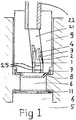
- FIG. 1 schematically shows a combustion pressure sensor assembly mounted in a surrounding engine component mounting structure 8.
- the engine component mounting structure 8 can be either a cylinder head or a body of a fuel injector of an internal combustion engine or any other engine part like a spark plug or glow plug.
- the combustion pressure sensor (CPS) has a sensor body 9, which conveniently can be made from a material like quartz, a ceramic material, or Kovar a low CTE stainless steel.
- optical light transmitting fibres 1, 2, 3, 4 are arranged with their ends facing a deformable membrane 7.
- a first central optical fibre 1 and a second central optical fibre 2 are positioned to detect a bending of the deformable membrane 7 that is mainly due to pressure variations, and only to a small extent due to temperature changes.
- a first outer side edge optical fibre 3 and a second outer side edge optical fibre 4 are positioned to detect enlargement at the outer edge of the deformable membrane 7 that is mainly due to temperature gain and only to a minor extent due to pressure variations. Values obtained from the pairs of central optical fibres 1, 2 and outer side edge optical fibres 3, 4 can then be compared using the burning gas temperature within the cylinder to eliminate the effect of thermo-shock, by calculation. Due to the construction of the membrane 7 and the different locations of the central optical fibres 1, 2 and outer side edge optical fibres 3, 4, the central optical fibres 1, 2 and outer side edge optical fibres 3, 4 detect a different deformation for the same pressure as a result of the thermo-shock.
- an effect of temperature on the deformation may be determined and with that, an effect of the temperature on the sensed pressure may be determined.
- the temperature in the cylinder, for example during combustion may be determined.
- the membrane 7 is shown as a generally domed structure convexly directed towards the source of combustion pressure. Nonetheless it would also be possible to inverse the position of the membrane, so that its domed structure is concavely directed towards the source of combustion pressure. In this proposed inverse position of the membrane 7 its domed structure when thermally expanding would be more closer to the optical fibre end or tip in the sensor body, rather than moving away therefrom. Depending on the particular construction of the combustion pressure sensor compensation for expansion of the membrane 7 may be found in other components to expand in an opposite direction.
- the location to which reference numeral 8 of the surrounding mounting structure points is an inwardly directed circumferential ridge contracted by the outer periphery of the membrane 7.
- the membrane 7 can directly transmit its heat to the surrounding structure 8 in such a way that there is no heat transfer barrier to be considered.
- the inwardly directed ridge of the surrounding structure 8 also forms a channel 6 between a combustion chamber 5 of an engine and the membrane 7 of the combustion pressure sensor.
- a heat shield 11 can optionally be positioned within the channel 6 to further reduce the temperature to which the membrane 7 will be exposed.
- soldered ends 25 of the outer side edge pair of optical fibres 3, 4 for temperature correction are positioned eccentrically with respect to the soldered ends 25 of the centre pair of optical fibres 1, 2 for measuring combustion pressure.
- the connection of the fibre ends 25 is orthogonal with respect to the lower face of the sensor body 9.
- An inclined channel 21 within the sensor body 9 enables the optical fibre 1, 2, 3, 4 to be positioned in this manner.
- a socket 22 centrally soldered into the sensor body 9 has an inner diameter suitable to guide and retain the optical fibres 1, 2, 3,4 outwardly of the combustion pressure sensor.
- optical fibres 1, 2, 3, 4 are fixed to the sensor body 9 by soldering or cementing.
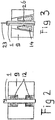
- the optical fibre such as the first central optical fibre 1
- the optical fibre can also be held in position with respect to the sensor body 9 by a pair of ferrules 12 opposite of a reduced diameter portion of the sensor body 9.
- the ferrules 12 is made of a material having a low expansion coefficient, such as quartz or ceramic material.
- a separation gap may be provided between a distal end of the ferrule and the sensor body. This separation gap may be established by narrowing an outer diameter of the ferrule at the distal end of the ferrule. Alternatively or additionally, an inner diameter of a bore in the sensor body increases towards the distal? end. The decrease of the outer diameter of the ferrule and/or the increase of the inner diameter of the bore in the sensor body may be stepwise, continuous, monotonous, linear, staggered, other, or a combination thereof. In one embodiment, the gap between the ferrule and the sensor body is at least partially and optionally fully filled with brazing paste and in another, the gap is left open.
- the circumferential gap provided in the sensor is only provided in the sensor body.
- a central part of the body in which a bore is available through which fibres are provided, either surrounded by a ferrule or not, extends to the distal end.
- a circumferential separation gap is provided between the sensor body part directly adjacent to the bore and an outer part of the sensor body.
- This separation gap is arranged to provide a thermal barrier between the sensor body and the fibres, and the membrane and the fibres.
- the separation gap may be filled with air, vacuum, or an isolating material like ceramic, wherein the material has a higher thermal resistance than the material comprised by the sensor body,
- the separation gap is provided circumferentially around the fibres, such that the effect of the combustion heat on fibre temperature can be kept as low as possible.
- a cutting ring 14 in a conical bore of the sensor body 9 can be used to keep each of the optical fibre ends in position with respect to the sensor body 9.
- the cutting ring 14 has an inwardly directed cutting edge 26 which only grips a coating of the optical fibre, such as that of the first central optical fibre 1.
- the uncoated portion 23 of the fibre 1 is smaller than the coated fibre.
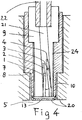
- FIG. 4 there is illustrated another embodiment of pressure sensor assembly mounted in a surrounding engine component 8, again in a schematic transverse cross section.
- the sensor body 9 holding the centre optical fibres 1, 2 and outer edge optical fibres 3, 4 is mounted in a steel sleeve 10.
- the steel sleeve 10 being mounted in the surrounding structure 8 of an appropriate engine component.
- a deformable membrane 13 is mounted flush with a surface of the combustion chamber 5, as indicated at reference numeral 20.
- the membrane 13 is welded to the steel sleeve 10.
- the welding of the membrane 13 to the steel sleeve 10 can be completed by a heat treatment to reduce tensions and/or to obtain a fine grained structure of the membrane.
- the quartz body 9 can be connected to the steel sleeve 10 in a variety of ways, for example by pressing against each other, or by a folding seam on the sleeve 10 to hold the sensor body 9.
- a thermic gap 24 is provided between the sensor body 9 and the steel sleeve 10.
- One of the optical fibres of each pair is used solely for guiding an emitted light beam to the reflective surface of the membrane 7, while the other optical fibre of each pair guides the light reflected from the reflective membrane surface.
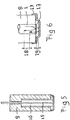
- FIG. 5 shows the alternative of a Fibre Brag Grating (FBG) measuring principle with a FBG fibre 15 for combustion pressure measurement.
- the FBG fibre 15 is positioned centrally in a for example quartz body 16 that is retained in the sensor body 9.
- Figure 6 shows the alternative of a Fabry-Perot measuring principle, where the light transmitted to the membrane 13 by optical fibre 1 is split into two beams by a dialectic mirror 17.
- This beam splitting by the dialectic mirror 17 results in different paths of interference causing a delay indicated by reference numeral 18, between the beam reflected by the dialectic mirror 17 and the beam reflected by the reflective surface of the membrane 13, which is positioned at a distance 19 of the dialectic mirror 17.
- FIGS 5 and 6 are simplified representations, and it is clear that the Fibre Brag Coating, or the Fabry-Pérot measuring principles can also be applied to the outer edge temperature correction optical fibres in any of the afore described embodiments.
- a combustion pressure sensor comprises a sensor body 9, at least one first optical fibre 1, 2 inserted into the sensor body 9, and a resiliently deformable membrane 7; 13 attached to the sensor body 9.
- the at least one first optical fibre 1, 2 is arranged for allowing measuring of a pressure induced deflection of the resiliently deformable membrane 9.
- An end 25 of the at least one first optical fibre 1, 2 is connected to the sensor body 9 in a manner that withstands temperatures within a range of temperatures hot enough to regenerate soot depositions on the resiliently deformable membrane 7; 13, yet cool enough to prevent melting of the resiliently deformable membrane 7; 13.
- At least one such combustion pressure sensor When included in an internal combustion engine, at least one such combustion pressure sensor is positioned with its resiliently deformable membrane 7; 13 in direct contact with a surrounding body 8 of an engine component for direct transfer of heat to the surrounding body 8 of the engine component, such as a cylinder head or fuel injector.
- FIG 7A shows a first practical pressure sensor 700 and Figure 7 B shows a details of a distal end of the first practical pressure sensor 700.
- the first practical pressure sensor 700 comprises a sensor body 710, through which a bore is provided. In the bore, a ferrule 730 is provided. In this embodiment, a distal end of the ferrule 730 does not extend through the bore up to a distal end of the body 710. In another embodiment, both distal ends are provided on one line.
- the ends of a first fibre module 742 and a second fibre module 744 extend such that they are in the same plane at the distal end of the body 710.
- the first fibre module 742 and the second fibre module 744 may comprise one fibre, two fibres or more fibres, in accordance with embodiment discussed above.
- a membrane 720 is provided at the distal end of the device body.
- the membrane 720 has a D-shaped cross-section, with a substantially flat centre part and a surrounding circumferential part that having an orientation substantially perpendicular to the centre part.
- the transition between the centre part and the circumferential outer part is preferably provided in a bend rather than a sharp corner.
- the membrane 720 is provided concavely in the sensor 700
- the bend preferably has a substantially constant radius.
- the bend has a substantially elliptical or parabolic shape, another shape, or a combination thereof.
- the distance between the distal end of the device body and/or distal ends of the fibre module is preferably in the order of 50 ⁇ m, between 20 ⁇ m and 70 ⁇ m.
- the properties of the membrane 720 are such that at a pressure of 350 bar, the deflection of the membrane is approximately between 7 ⁇ m and 10 ⁇ m.
- the ferrule 730 is narrower at the distal end compared to the rest of the ferrule 730.
- the narrowing is established by a step function in the outer diameter of the ferrule 730.
- the bore in the body 710 has a substantial constant cross-section, which results in an airgap between 712 the ferrule 730 and the device body 710, the airgap is meant for insulating the temperature in the inner heatshield formed by the distal end of the body 710 picking up the majority of the flux heat from the membrane and transporting it to the engine cooling.
- Figure 8A shows a second practical pressure sensor 800 and Figure 8 B shows a details of a distal end of the first practical pressure sensor 800.
- the second practical pressure sensor 800 comprises a sensor body 810, through which a bore is provided.
- the sensor body 810 may be part of a larger entity, like a fuel injector for a Diesel engine.
- a first ferrule 830 is provided in the bore.
- a distal end of the first ferrule 830 does not extend through the bore up to a distal end of the body 810.
- both distal ends are provided on one line.
- the ends of a first fibre module 842 and a second fibre module 844 extend such that they are in the same plane at the distal end of the body 810.
- the first fibre module 842 and the second fibre module 844 may comprise one fibre, two fibres or more fibres, in accordance with embodiment discussed above.
- a membrane 820 is provided at the distal end of the device body.
- the membrane 820 has a D-shaped cross-section, with a substantially flat centre part and a surrounding circumferential part that having an orientation substantially perpendicular to the centre part.
- the transition between the centre part and the circumferential outer part is preferably provided in a bend rather than a sharp corner.
- the membrane 820 is provided convexly in the sensor 800.
- the bend preferably has a substantially constant radius.
- the bend has a substantially elliptical or parabolic shape, another shape, or a combination thereof.
- the distance between the distal end of the device body and/or distal ends of the fibre module is preferably in the order of 50 ⁇ m, between 20 ⁇ m and 70 ⁇ m.
- the properties of the membrane 820 are such that at a pressure of 350 bar, the deflection of the membrane is approximately between 6 ⁇ m and 20 ⁇ m.
- the first ferrule 830 is narrower at the distal end compared to the rest of the first ferrule 830.
- the narrowing is established by a step function in the outer diameter of the first ferrule 830.
- the bore in the body 810 has a substantial constant cross-section, which results in an airgap 812 between the first ferrule 830 and the device body 810.
- the second practical pressure sensor 800 further comprises a second ferrule 850.
- the second ferrule 850 partially overlaps with the first ferrule 830.
- the first ferrule 830 is located at the outside at the overlapping part, as a mantle to the second ferrule 850.
- an optional third ferrule 860 is provided around the ensemble of the first ferrule 830 and the second ferrule 850.
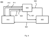
- FIG. 9 shows a motor management system 900, comprising at least one combustion pressure sensor 910 according to any of the abovementioned embodiments.
- the motor management system 900 further comprises a control module 920, arranged to receive an external signal 942 and arranged to send a control signal 931 to an internal combustion engine 930.
- the control module 920 is further arranged to send a first light beam 911 to the combustion pressure sensor 910 and to receive back a reflection 912 of at least part of the first light beam.
- the control module 920 is furthermore arranged to send a second light beam 921 to the combustion pressure sensor 910 and to receive back a reflection 922 of at least part of the second light beam.
- the combustion pressure sensor 910 is arranged to be exposed to a pressure in the combustion engine 930 via a conduit 932.
- the external signal 942 may be based on data acquired from an internal combustion engine, wherein said data may comprise a combustion temperature, intake air temperature, oxygen level, fuel-to-air ratio, engine RPM, engine load, fuel tank level, intake air pressure, spark timing, throttle, engine stroke, crank angle, any other parameter or any combination thereof.
- the control signal 931 may comprise a signal based on data acquired from one of the external signal 942, reflection 911 of the first light beam, reflection 922 of the second light beam, or any combination thereof.
- the control signal 931 is arranged to control the operation of the internal combustion engine 910 according to an optimization parameter, e.g. fuel efficiency or emissions.
- Fig. 10 shows a method 1000 of controlling operation of an internal combustion engine comprising a crank shaft, a piston and a cylinder, wherein the method comprises providing a combustible mixture in the cylinder in part 1001.
- the combustible mixtures comprises at least oxygen and a first combustible at a first mixture ratio.
- the procedure further comprises obtaining an annular position of the crank shaft in part 1002. Execution of this part triggers combustion of the mixture at a first annular position of the crank shaft in part 1003.
- a temperature of the combustible mixture in the cylinder is obtained during combustion. The obtained temperature is compared to a pre-determined range in part 1005. If the temperature is out of the range, at least one of the first mixture ratio and the first annular position of the crank shaft at which combustion is triggered is adjusted in part 1006.
- the first combustible may be a spark-ignition type fuel, such as gasoline, LPG, methanol, ethanol, bioethanol, natural gas, hydrogen, nitromethane, any other spark-ignition type fuel, or any combination thereof.
- the first mixture comprises said first combustible and further comprises oxygen.
- the first mixture may optionally comprise recirculated exhaust gasses.
- crankshaft position sensor such as a hall effect sensor, optical sensor, harmonic balancer or inductive sensor. This position may be a relative position or an absolute position.
- the combustion of the mixture at a first annular position of the crank shaft in part 1003 can either be triggered by introducing a spark in the cylinder, using a spark plug.
- a second combustible mixture may be introduced in the cylinder, wherein said second combustible mixture is of a compressive ignition type, such as Diesel.
- the second combustible mixture Upon compression of the second combustible mixture, the second combustible mixture will ignite and act as a spark for the ignition of the first combustible mixture.
- the second combustible matter injected after injection of the first combustible matter, executed self-combustion at a lower pressure than the first combustible matter.
- the timing of the combustion of the combustible mixture can be controlled by adjusting at least one of the first mixture ratio, timing of the injection of the second combustible mixture, activation of a sparkplug or another combustion trigger.
- Obtaining the temperature of the mixture in the cylinder during combustion in part 1004 may be done directly using a temperature sensor, or alternative the temperature may be estimated from different engine parameters. These different engine parameters comprise a pressure in the cylinder, and the volume occupied by the mixture in the cylinder, which can be derived from known cylinder parameters such as a bore and a stroke, and the crank angle which determines the position of a piston in the cylinder.
- the combustion pressure sensor discussed above may be used for determining the temperature in the cylinder during combustion. Either the deflection measured by the first fibre module or the second module is used, in combination with the volume occupied by the combustible mixture, and a pre-determined constant based on the content of the combustible mixture. Otherwise, a difference in deflection measured by the first fibre module and the second fibre module can be used to obtain the temperature in the cylinder. These methods may be used to determine a temperature during combustion, relative to a reference temperature.
- the obtained temperature is compared to a pre-determined temperature range, wherein said temperature range is pre-determined to optimize for minimizing certain emissions, such as NO x , CH 4 , soot, particulate matter (PM), any other emission, or any combination thereof.
- certain emissions such as NO x , CH 4 , soot, particulate matter (PM), any other emission, or any combination thereof.
- the data obtained from a first combustion, which occurred earlier than the second combustion is used. Then, in order to control the temperature, at least one of the air-to-fuel ratio of the combustible mixture, an amount of second combustible provided to the cylinder, the injection timing of one or more injections of the second combustible an duration of injection of the second combustible are adjusted. Any combination of said control parameters may be also be adjusted to control the temperature in the cylinder during combustion. This usage of data obtained from a previous combustion may form a closed-loop control system aimed at keeping the combustion temperature inside the pre-determined temperature range.
Landscapes
- Engineering & Computer Science (AREA)
- Chemical & Material Sciences (AREA)
- Combustion & Propulsion (AREA)
- Mechanical Engineering (AREA)
- General Engineering & Computer Science (AREA)
- Physics & Mathematics (AREA)
- General Physics & Mathematics (AREA)
- Signal Processing (AREA)
- Analytical Chemistry (AREA)
- Measuring Fluid Pressure (AREA)
- Combined Controls Of Internal Combustion Engines (AREA)
- Electrical Control Of Air Or Fuel Supplied To Internal-Combustion Engine (AREA)
Description
- The invention relates to an improved combustion pressure sensor using optical fibre technology, and being in particular adapted to detect the combustion pressure in an internal combustion engine. The invention also relates to a combustion engine equipped with the improved combustion sensor.
- Combustion pressure sensors enable to achieve excellent engine control with a minimum of sensors. The combustion pressure sensor can provide information about the combustion directly from the combustion chamber. Such information includes effects of ignition timing, of valve timing, and supply of energy, but would also enable detection of engine damage hazards, like auto-ignition, engine knock, blow-by, exceeding of maximum combustion pressure (Pmax) or exceeding of too much pressure rise per crank angle Dp/da.
- Known combustion pressure sensors, such as those available from Optrand and described in
US 6,131,465 can however only withstand a limited working temperature at the risk of the fixation or connection between their optical fibre and the body of the sensor becoming damaged. The maximum temperature allowed by the glass bond is at best 510 °C or lower, which requires a sensor tip temperature not to exceed a temperature of 510 °C. The prevention of soot fouling of the sensor tip would require a temperature of at least 535 °C, while in practice the sensor tip could well become exposed to combustion temperatures of up to 800 °C. Another disadvantage of the known combustion pressure sensors is their sensitivity to temperature variations, known as thermo-shock. This sensitivity to temperature changes distorts the pressure measurements in a rather unpredictable manner. A still further disadvantage of the known combustion pressure sensors is their insufficient resistance to engine knock, knock results in a raise of temperature with an easy 10.000°C. As a result of these disadvantages, the known combustion pressure sensors have only seen limited use in engine research, and on test bed engines but not successfully in the field unfortunately. - Known combustion pressure sensor that are sufficiently small, e.g. 2.5 mm in diameter, to be build in into engine components, e.g. injectors or glowplugs, are not proven to be suitable for continuous usage. Larger diameter combustion pressure sensors, with diameters e.g. larger than 5 mm, are more reliable, but have the drawback of having the large diameter. Furthermore, some type combustion pressure sensors had to be equipped with a liquid cooling system. No such sensors have yet proven suitable for continuous use on commercially produced internal combustion engines as part of an engine management system.
-
US 5,146,083A fibre optic microphone is provided for measuring fluctuating pressures. An optical fibre probe having at least one transmitting fibre for transmitting light to a pressure-sensing membrane and at least one receiving fibre for receiving light reflected from a stretched membrane is provided. the microphone comprises one centrally located transmitting fibre and six surrounding receiving fibres. - It is hence an object of the present invention to provide an improved combustion pressure sensor according to
claim 1 that can be used as part of an engine management system in commercially produced and operated internal combustion engines. Another object of the present invention is to provide a method of determining a temperature in a cylinder of a combustion engine by means of a combustion pressure sensor according toclaim 1 and to provide a computer software according toclaim 9 to execute the method according to claim 8. Further, another object of the present invention is to provide a method of controlling operation of an internal combustion engine according toclaim 10, using the method of claim 8. - In particular a combustion pressure sensor in accordance with the invention can comprise a sensor body, at least one first optical fibre inserted into the sensor body, and a resiliently deformable membrane attached to the sensor body, the membrane having a reflective surface, wherein the at least one first optical fibre is arranged for allowing measuring of a pressure induced deflection of the resiliently deformable membrane, wherein an end of the at least one first optical fibre module is connected to the sensor body to guide a light beam to the reflective surface and to guide the reflected light, at least one second optical fibre module is inserted into the sensor body to guide a light beam to the reflective surface and to guide the reflected light, the at least one second optical fibre module is arranged for allowing detection of a temperature induced thermal expansion of the resiliently deformable membrane to enable temperature correction of pressure related values obtained by the at least one first optical fibre module, the first optical fibre module is positioned centrally with respect to the resiliently deformable membrane; and the second optical fibre module is positioned adjacent to an outer edge of the resiliently deformable membrane.
- The at least one first optical fibre "set" can be arranged for allowing measuring of a pressure induced deflection of the resiliently deformable membrane, and an end of the at least one second "set" optical fibres can be connected to the sensor body in a manner that withstands temperatures within a temperature range hot enough to regenerate soot depositions on the resiliently deformable membrane, yet cool enough to prevent melting of the resiliently deformable membrane. The temperature range of such a combustion pressure sensor can be between 540 °C and 750 °C. The sensor body can optionally be made of a material having a relatively low expansion coefficient lower than α6 (*10-6m/m K-1). In order to expand minimum in relation to the fibre that is made from Quartz, the body therefore could be made from Kovar (low Coefficient of Thermal Expansion "CTE" Stainless Steel), Quartz or Ceramic material.
- In the combustion pressure sensor the at least one first optical fibre can be connected to the sensor body by either Soldering or Brazing, by using for example a vacuum furnace or non vacuum and induction and or Handy Hi Temp Flux, and Vacuum Brazing Paste HF350/60-521/90Bl which can both be delivered by www.lucasmilhaupt.com, bonding, cementing like Ceramabond that can be delivered by www.aremco.com, or press fitting.
- Also the manner of connecting the at least one first optical fibre to the sensor body can be effective to resist disconnection under temperature induced expansion and contraction.
- Optionally, the end of the at least one first optical fibre can be connected to the sensor body by at least one ferrule. In that regard the end of the at least one first optical fibre can also be connected to the sensor body by a pair of ferrules oppositely engaging a portion of the sensor body. In connection with these options the at least one ferrule can be made of a material having a relatively low expansion coefficient, including either quartz or ceramic.
- Alternatively the end of the at least one first optical fibre can also be connected to the sensor body by a cutting ring, which is arranged to cut only in a fibre coating, and not in the fibre itself. Either one of the optional connections of the end of the at least one first optical fibre to the sensor body can also be combined with the connection being arranged to put the connected end under tension, which can be accomplished by a spring.
- In case the combustion pressure sensor can be placed cold enough than optionally a polyamide coated fiber can be connected to the ferule or body by for example polyamide injection moulding.
- In any combustion pressure sensor with one or more of the abovementioned features, at least one second optical fibre can be inserted into the sensor body, and then the at least one second optical fibre can be arranged for allowing detection of a temperature induced thermal expansion of the resiliently deformable membrane to enable temperature correction of pressure related values obtained by the at least one first optical fibre. In such a combustion pressure sensor the at least one first optical fibre can be positioned centrally with respect to the resiliently deformable membrane, while the at least one second optical fibre can be positioned adjacent to an outer edge of the resiliently deformable membrane. Then the at least one second optical fibre can be one of a second pair of optical fibres, while one optical fibre of the second pair emits light, and the other optical fibre of the second pair allows measuring of an intensity of light reflected by a reflective surface on the outer edge of the resiliently deformable membrane.
- In a combustion pressure sensor according to the invention the at least one first optical fibre can be one of a first pair of optical fibres, while one optical fibre of the first pair emits light, and the other optical fibre of the first pair allows measuring of an intensity of light reflected by a reflective surface on a central part of the resiliently deformable membrane. In this configuration, at least one end of each of the optical fibres comprised by the first pair is placed at a distance of the reflective surface to allow the reflected light to be reflected in one of the optical fibres.
- In a combustion pressure sensor according to the invention the at least one first optical fibre alternatively can be arranged for optical beam splitting. The optical beam splitting can then be obtained by a dialectic mirror in accordance with a Fabry-Pérot measuring principle, and cause a difference in paths of interference.
- As a further alternative the at least one first optical fibre can also be arranged for detection of changes of optical fibre length, by using a Fibre Brag Grating (FBG) measuring principle. In order to use the fibre Brag Grating measuring principle, the at least one optical fibre comprises multiple segments / lenses of which at least one optical transmission factor is arranged to change as a result of changes in strain in the at least one first optical fibre. The optical transmission factor is in one embodiment of the at least one first optical fibre the refractive index. The refractive index is different for different wavelengths of light. When the strain in the segments changes, an absolute change in the refractive index occurs, which in turn can be measured. From this measurement the strain in the segment can be determined. As the strain in the segments are a result of deformation of the flexible membrane, to which an end of the at least one first optical fibre is attached, the deformation of the flexible membrane at the point to which the at least one first optical fibre is attached can be determined. The other end of the at least one first optical fibre is attached at another point, such that the at least one first optical fibre length can only change due to deformation of the flexible membrane to which it is attached.
- An internal combustion engine in accordance with the invention can include at least one combustion pressure sensor with one or more of the above features. In such an internal combustion engine the at least one combustion pressure sensor can be positioned with its resiliently deformable membrane in direct contact with a surrounding body of an engine component for possibly direct transfer of heat to the surrounding body. The engine component can either be a fuel injection device or a cylinder head or any other engine part.
- In a further embodiment of the internal combustion engine of the invention the resiliently deformable membrane can be separated from a combustion chamber of the internal combustion engine by a channel in the engine component. Such a channel can have a length that is selected to commensurate with the working temperature range of the resiliently deformable membrane. Furthermore a heat shield can be positioned within the channel at a location interposed between the combustion chamber and the resiliently deformable membrane.
- Another variation of the internal combustion engine of the invention can further include an engine management control system that is connected to the at least one combustion pressure sensor for governing operation of the engine in commercial use. When in at least one second optical fibre is included in the at least one combustion pressure sensor, with the at least one second optical fibre arranged for allowing detection of a temperature induced thermal expansion of the resiliently deformable membrane, and the engine management control system can then be adapted to calculate temperature correction of pressure related values obtained by the at least one first optical fibre. The engine management control system further comprises a first light source, arranged to provide a first light beam to the at least one first optical fibre. Also comprised by the engine management control system is a first light sensor, arranged to receive a reflected part of the first light beam. When provided with at least one second optical fibre, the engine management control system is arranged to determine a temperature difference between multiple locations of the resiliently deformable membrane. To provide the second optical fibre with a light beam, a second light source and a second light sensor are provided in the engine management control system.
- Another feature of the invention is the ability to measure, in real-time, the temperature in the cylinder. This information can be used to optimise temperature losses in the engine and therewith increase engine efficiency.
- The combustion pressure sensor of the invention can use the working principle of optical fibre technology to measure intensity of light reflected by a deformable membrane to record bending of the membrane caused by pressure variations. The temperature of the membrane is controlled by design of the sensor and its mounting in a surrounding engine component to be, in use, above a value of 540 °C to counteract / regenerate deposition of soot on the membrane, and below a maximum temperature value of 750 °C to prevent damage to the membrane. This working temperature range is made possible by a fixation of the optical fibre that can withstand these elevated temperatures. Furthermore the combustion pressure sensor is optionally mounted with its membrane in direct contact with a surrounding engine component, rather than that the heat of the membrane has first to dissipate via the sensor body before reaching the engine component, this to shortcut the distance for dissipating the heat.
- An other way to shortcut the heat transfer from the membrane to the coolant of the engine is to introduce a airgap on the nose of the ferule in order to isolate the ferule and give enough material around it to transfer this heat.
- One aspect is that the temperature to which the membrane of the combustion pressure sensor becomes exposed is adapted to the required working range of temperatures. If the temperature of the membrane would get below a value of 540 °C it will become contaminated by soot and measurements will become inaccurate or become inhibited altogether. When during maximum power operation of the internal combustion engine the membrane of the combustion pressure sensor would get to its upper temperature limit, occurrence of detonation or engine knock could easily result in destruction of the membrane. It is therefore important that the temperature to which the membrane of the combustion pressure sensor is exposed does not exceed a maximum of 750 °C to remain sufficiently robust. Hence the benefit of an improved heat transfer cooperation between the sensor and the surrounding body, such as cylinder head or injector body in which it is mounted.
- This aspect thus also relates to the combination of the sensor and its surrounding body, and the features relating to temperature control also work together to enable continuous use of the sensor of the invention in conjunction with an engine management control unit. Additional cooling of the sensor may be obtained by locating it in proximity of cooling water passages or fuel delivery conduits. In air cooled combustion engines a location close to nearby cooling ribs can be selected.
- Other parameters, such as material properties, or distance from the heat source, can also be varied to obtain the best possible membrane surface temperature range for the combustion pressure sensor. Under particular engine operating conditions it is also conceivable that the cooling water temperature, or the combusted mass of the internal combustion engine are adjusted to prevent damage to the combustion pressure sensor, or to keep it within its optimal working temperature range. To be able to operate at a temperature higher than 540 °C, it is important that the connection between any fibre and the sensor body can withstand such a temperature.
- The surrounding body can be formed by different materials, such as aluminium or cast iron (cylinder heads), or steel (injector body or separate adapter). A separate adapter for mounting the combustion pressure sensor in an internal combustion engine can also include a spark plug or a glow plug. Important is that the membrane of the combustion pressure sensor can dissipate heat to its surrounding body as directly as possible. A heat shield can also be applied to reduce the heat to which the membrane is directly exposed.
- It is the main purpose of this invention to make a combustion pressure sensor that does not need a heatshield. A Heatshield lowers the thermos-shock. But the combustion pressure sensor does not need that because it takes away the thermos-shock. It does so by means of the second fibre "set" with the two fiber sets its possible to calculate the deflection coming from the heat change of the membrane and the deflection coming from the pressure on the membrane. This is done by the principle that you now have two equations with two unknowns and this is mathematically solvable. The big disadvantage of the heatshield is soot clogging problems that give the sensor a too short life <3months to use in an application outside a engine laboratory. So the only reason to mention a heatshield is not to exclude the option to use one as a plan B for new upcoming situations in the future.
- Another aspect of the invention is related to fixation of the optical fibre to the sensor body, which is also sensitive to temperature. The temperature per cycle in a combustion chamber of an internal combustion engine can vary between 0 °C and 10,000 °C, depending on the type of engine. Even in the sheltered environment selected for the combustion pressure sensor this means that the connection of the optical fibres to the sensor body should also be able to follow quickly changing temperature extremes without endangering the bond between fibre and sensor body. This bond could be endangered when the bonding material disintegrates, or when the expansion coefficient of the optical fibre is greatly different from the material of the sensor body.
- If the optical fibre becomes detached from the sensor body, its position with respect to the membrane will become undefined causing the sensor readings to be useless. The invention proposes a sensor body of a material having a relatively low expansion coefficient, such as quartz or ceramic material. Preferably the expansion coefficient is lower than α6 (*10-6m/m K-1) to ensure that the optical fibres are robustly fixed in the sensor body.
- Alternatively or additionally the invention proposes the use of ferrules to fix the optical fibre with respect to the sensor body. Such ferrules also can be made of a material having a low expansion coefficient, such as quartz or ceramic material. Also soldering, brazing, gluing, injection moulding or even press fit connections may then be employed without risk of working loose as a result of changing temperatures.
- The thermo-shock problem is solved by enabling membrane deformations caused by heat to be distinguished from membrane deformations caused by pressure. Conventional combustion pressure sensors show thermo-shock sensitivity of up to 30%, especially when a heatshield is not been used. The invention proposes to measure both the enlargement of the membrane caused mainly by a raise in temperature, as well as the bending of the membrane caused mainly by a change in pressure. The obtained measuring value can then be used to calculate the actual pressure value. An extra set of optical fibres can be used to measure the membrane enlargement or expansion caused by heat.
- While one optical fibre may solely be used to guide a light beam to a reflective surface of the sensor membrane, and another to guide the reflected light beam, it is also possible to use a single optical fibre to detect membrane deformation. This can be achieved by using optic beam splitting, or by using Piezo, Fabry-Pérot or Fibre Bragg Grating (FBG) measuring principles.
- Alternatively the optical fibre or optical fibres can be attached to the sensor body by clamping. While fixation by brazing or soldering may initially be preferred because it is both robust and small, a variety of other fixation options may nonetheless be successfully employed. One option is a cutting ring akin to those in use with pipe connections and fittings. It is also possible to tension the optical fibre between two ferrules, either by means of a spring or by bringing the optical fibre itself in a pre-tensioned state. The ferrules can be fixed to the optical fibre by soldering, by clamping, or by melting of the optical glass fibre. When a cutting ring is used, it is preferred that this only cuts into the coating of the optical fibre.
- Yet another aspect of the invention is to control the temperature of the combustion in at least one cylinder of an internal combustion engine as a combustion room during combustion. It is known that during combustion of a combustible in an internal combustion engine NOx may be formed and CH4 (methane) may not be burned completely. It is an objective of this invention to optimize the temperature of combustion in the internal combustion engine to minimise emissions like NOx, , CH4 or any other emission like CO and THC .
- Experiments have shown that if the temperature of combustion exceeds 1500 °C, the NOx emissions increases significantly. Experiments have further shown that if the temperature of combustion becomes below 1300 °C, the CH4 emissions increases significantly. It is therefore preferred to improve control the combustion process in an internal combustion engine to keep the combustion temperature within a specific range.
- A control module is used to control different engine parameters based on information provided by sensors provided at or in the cylinder. The information provided comprises at least one of a pressure inside the cylinder, an available volume in the cylinder for fuel and oxygen, a temperature in the cylinder, an amount of injected fuel, or any other engine parameter.
- The control module is arranged to calculate the theoretical combustion temperature out of pressure measured in the cylinder corrected for the real volume knowing the piston position it is also possible due to this invention to directly calculate the combustion temperature by the temperature value of the CPS membrane given by the CPS affect at least one of an air-to-fuel ratio (lambda), an ignition timing, an amount of fuel injected, and an amount of times fuel is injected for one combustion cycle. In this context, air is to be understood as a mixture of approximately one fifth of oxygen (O2), four fifths of nitrogen (N2) and small amounts of other gases.
- A first method of obtaining the temperature inside the cylinder is by estimating the temperature using the ideal gas equation:

- The pressure inside the cylinder can be obtained from the combustion pressure sensor, the volume can be derived from cylinder parameters such as a bore, a stroke, and a crank shaft angle. The constant k can be derived from a known air-to-fuel ratio and an amount of fuel injected in the cylinder.
- The ideal gas law will only give a global temperature inside the cylinder and disregards local temperature variations inside the cylinder, which may result in temperatures lower or higher than the global temperature. For homogenous combustion principles like Homogeneous Charge Compression Ignition (HCCI) and Reactive Controlled Compression Ignition (RCCI), this approximation suffices in being accurate enough to provide a temperature value that can function as a feedback control parameter to continually optimise and monitor emissions of the engine. In RCCI, a first combustible is introduced in a cylinder along with a pre-determined amount of oxygen or air and optionally a pre-determined amount of recirculated exhaust gases.
- The first combustible is allowed to mix with the oxygen and optional exhaust gases. Next, a second combustible is introduced in the cylinder, wherein the second combustible ignites at a lower pressure as the first combustible. Single or multiple injections of second combustible may be performed, and the second combustible is ignited due to a high pressure inside the cylinder. The combustion of the second combustible acts as a spark to ignite the first combustible.
- Another method of obtaining the temperature inside the cylinder is by comparing the deflection of the resilient membrane measured by at least one of the first fibre module and second fibre module. Values may be used to compensate detected pressure and in just the same way to provide an indication of the temperature.
- Because the combustion inside the cylinder when using RCCI is very homogenous, the temperature differences inside the cylinder during combustion will be relatively small, compared to conventional spark-ignition (SI) or compression ignition (CI) engines. Due do the relatively small temperature range inside the cylinder aimed to be achieved, the approximation of the combustion temperature using the ideal gas law is sufficient for accurate control of said temperature in the cylinder.
- One of the control parameters for controlling the temperature during combustion inside the cylinder is identified as being the ignition timing. This timing can, for example, be expressed in terms of degrees crank shaft angle. E.g., an increase of 0.1 degrees crank angle in ignition timing can increase combustion temperature with 300 °C.
- A method of controlling operation of an internal combustion engine can be used to control the temperature inside a cylinder during combustion. In this method, first an obtained temperature during combustion is compared to a pre-determined temperature range. If the obtained temperature is found to be below the pre-determined temperature range, the method may bring forward a moment of triggering of the combustion in a subsequent combustion stroke. Alternatively, if the obtained temperature is found to be above the pre-determined temperature range, the method may delay the triggering of combustion in a subsequent combustion stroke.
- The obtaining of the combustion temperature in a first combustion stroke, and using said obtained temperature to adjust certain parameters of the subsequent combustion stroke, may form a closed control loop for controlling the combustion temperature in the cylinder.
- The delay of the triggering of combustion comprises at least one of delaying a moment at which the second combustible is injected, and reducing an amount of second combustible provided to the cylinder. The bringing forward of the triggering of combustion comprises at least one of bringing forward a moment at which the second combustible is injected, and increasing an amount of second combustible.
- The moment at which the second combustible is injected and the amount of second combustible provided to the cylinder may be controlled by the control module, wherein in the control module an optimisation algorithm may be used to calculate an optimal combination of moment of injection and amount of combustible to be injected to achieve the desired combustion temperature. The algorithm may be provided with calibration data specific to the engine or cylinder. Additionally or alternatively, the algorithm may be provided with know information on properties of the second combustible, such as a flash point, density, lowest auto-ignition temperature, stoichiometric combustion ratio, any other relevant property, or any combination thereof.
- The second combustible may be injected in one, two or more stages. In different stages, equal or different amounts of second combustible may be injected into the cylinder. In particular a second or further injection is provided for triggering the combustion. When the second combustible is injected in two stages, the delay of the moment at which the second combustible is injected comprises delaying the second injection stage relative to the first injection stage. Furthermore, when injecting the second combustible in two stages, the bringing forward of the moment at which the second combustible is injected comprises bringing forward the second injection stage relative to the first stage.
- The combustion may be triggered by injecting a second combustible in the cylinder, wherein the second combustible preferably is one of a compression ignition type, e.g. Diesel. Additionally, the combustion may be triggered by increasing the pressure in the cylinder wherein the second combustible is provided to such a pressure that the second combustible is ignited. The ignition of the second combustible is furthermore related to the temperature inside the cylinder in which the second combustible is provided.
- In an alternative method of controlling operation of the internal combustion engine, the obtained temperature may fall within the pre-determined temperature range. In such a case, the control method may be aimed at controlling the temperature to a preferred temperature within the pre-determined temperature range by using any of the abovementioned methods of controlling the temperature during combustion, any other control method, or any combination thereof.
- Another control parameter for controlling the temperature during combustion inside the cylinder is an air-to-fuel ratio (lambda) inside the cylinder during combustion. The lambda can be controlled by measuring the composition of the exhaust gas and by controlling the amount of fuel provided to the cylinder to be combusted.
- Further advantageous aspects of the invention will become clear from the appended description and in reference to the accompanying drawings, in which:
- Figure 1:
- shows a schematic transverse cross section of a combustion pressure sensor assembly mounted in an engine component;
- Figure 2:
- shows a detail showing an alternative fixation of an optical fibre using a pair of ferrules, in such a way that the pre-tensioning of the fiber works as a spring to keep the fiber in place;
- Figure 3:
- shows a detail showing another alternative cutting ring fixation of an optical fibre;
- Figure 4:
- shows a schematic transverse cross section of another embodiment of pressure sensor assembly mounted in an engine component;
- Figure 5:
- shows a schematic transverse cross section of a combustion pressure sensor using an alternative Fibre Bragg Grating measuring principle; and
- Figure 6:
- shows a partial schematic transverse cross section of a combustion pressure sensor using an alternative Fabry-Pérot measuring principle.
- Figure 7 A:
- shows a cross section of a first practical sensor;
- Figure 7 B:
- shows a close-up of the cross section of a first practical sensor;
- Figure 8 A:
- shows a cross-section of a second practical sensor; and
- Figure 8 B:
- shows a close-up of the cross-section of a second practical sensor; and
- Figure 9:
- shows a schematic overview of a motor management system comprising a combustion pressure sensor
- Figure 10:
- shows a method for controlling operation of an internal combustion engine
- In a transverse cross section
Figure 1 schematically shows a combustion pressure sensor assembly mounted in a surrounding engine component mounting structure 8. In this example the engine component mounting structure 8 can be either a cylinder head or a body of a fuel injector of an internal combustion engine or any other engine part like a spark plug or glow plug. The combustion pressure sensor (CPS) has asensor body 9, which conveniently can be made from a material like quartz, a ceramic material, or Kovar a low CTE stainless steel. Within thesensor body 9 opticallight transmitting fibres deformable membrane 7. - A first central
optical fibre 1 and a second central optical fibre 2 are positioned to detect a bending of thedeformable membrane 7 that is mainly due to pressure variations, and only to a small extent due to temperature changes. - A first outer side edge
optical fibre 3 and a second outer side edgeoptical fibre 4 are positioned to detect enlargement at the outer edge of thedeformable membrane 7 that is mainly due to temperature gain and only to a minor extent due to pressure variations. Values obtained from the pairs of centraloptical fibres 1, 2 and outer side edgeoptical fibres membrane 7 and the different locations of the centraloptical fibres 1, 2 and outer side edgeoptical fibres optical fibres 1, 2 and outer side edgeoptical fibres - This results in a reliable value of the combustion pressure, which is a parameter that enables to control the combustion process in an engine in a novel way for optimal efficiency, reliability, power and emissions. At the same time also the temperature course in the cylinder is measured, which can be used to calculate temperature losses which enables to raise efficiently. The
membrane 7 is shown as a generally domed structure convexly directed towards the source of combustion pressure. Nonetheless it would also be possible to inverse the position of the membrane, so that its domed structure is concavely directed towards the source of combustion pressure. In this proposed inverse position of themembrane 7 its domed structure when thermally expanding would be more closer to the optical fibre end or tip in the sensor body, rather than moving away therefrom. Depending on the particular construction of the combustion pressure sensor compensation for expansion of themembrane 7 may be found in other components to expand in an opposite direction. - As can also be seen in
Figure 1 the location to which reference numeral 8 of the surrounding mounting structure points, is an inwardly directed circumferential ridge contracted by the outer periphery of themembrane 7. At this location themembrane 7 can directly transmit its heat to the surrounding structure 8 in such a way that there is no heat transfer barrier to be considered. The inwardly directed ridge of the surrounding structure 8 also forms achannel 6 between acombustion chamber 5 of an engine and themembrane 7 of the combustion pressure sensor. A heat shield 11 can optionally be positioned within thechannel 6 to further reduce the temperature to which themembrane 7 will be exposed. - Further it is illustrated in
Figure 1 that soldered ends 25 of the outer side edge pair ofoptical fibres optical fibres 1, 2 for measuring combustion pressure. The connection of the fibre ends 25 is orthogonal with respect to the lower face of thesensor body 9. Aninclined channel 21 within thesensor body 9 enables theoptical fibre socket 22 centrally soldered into thesensor body 9 has an inner diameter suitable to guide and retain theoptical fibres - In the embodiment of
Figure 1 as explained theoptical fibres sensor body 9 by soldering or cementing. - Alternatively as shown in
Figure 2 the optical fibre, such as the first centraloptical fibre 1, can also be held in position with respect to thesensor body 9 by a pair offerrules 12 opposite of a reduced diameter portion of thesensor body 9. Theferrules 12 is made of a material having a low expansion coefficient, such as quartz or ceramic material. - In an additionally envisioned embodiment of the pressure sensor assembly, a separation gap may be provided between a distal end of the ferrule and the sensor body. This separation gap may be established by narrowing an outer diameter of the ferrule at the distal end of the ferrule. Alternatively or additionally, an inner diameter of a bore in the sensor body increases towards the distal? end. The decrease of the outer diameter of the ferrule and/or the increase of the inner diameter of the bore in the sensor body may be stepwise, continuous, monotonous, linear, staggered, other, or a combination thereof. In one embodiment, the gap between the ferrule and the sensor body is at least partially and optionally fully filled with brazing paste and in another, the gap is left open.
- In another embodiment, the circumferential gap provided in the sensor is only provided in the sensor body. In this embodiment, a central part of the body in which a bore is available through which fibres are provided, either surrounded by a ferrule or not, extends to the distal end. Between the sensor body part directly adjacent to the bore and an outer part of the sensor body, a circumferential separation gap is provided.
- This separation gap is arranged to provide a thermal barrier between the sensor body and the fibres, and the membrane and the fibres. The separation gap may be filled with air, vacuum, or an isolating material like ceramic, wherein the material has a higher thermal resistance than the material comprised by the sensor body, The separation gap is provided circumferentially around the fibres, such that the effect of the combustion heat on fibre temperature can be kept as low as possible.
- Also as shown in
Figure 3 , a cuttingring 14 in a conical bore of thesensor body 9 can be used to keep each of the optical fibre ends in position with respect to thesensor body 9. The cuttingring 14 has an inwardly directed cuttingedge 26 which only grips a coating of the optical fibre, such as that of the first centraloptical fibre 1. As schematically illustrated inFigure 3 , theuncoated portion 23 of thefibre 1 is smaller than the coated fibre. - Now reverting to
Figure 4 there is illustrated another embodiment of pressure sensor assembly mounted in a surrounding engine component 8, again in a schematic transverse cross section. Here thesensor body 9 holding the centreoptical fibres 1, 2 and outer edgeoptical fibres steel sleeve 10. Thesteel sleeve 10 being mounted in the surrounding structure 8 of an appropriate engine component. In this embodiment adeformable membrane 13 is mounted flush with a surface of thecombustion chamber 5, as indicated atreference numeral 20. Themembrane 13 is welded to thesteel sleeve 10. The welding of themembrane 13 to thesteel sleeve 10 can be completed by a heat treatment to reduce tensions and/or to obtain a fine grained structure of the membrane. Thequartz body 9 can be connected to thesteel sleeve 10 in a variety of ways, for example by pressing against each other, or by a folding seam on thesleeve 10 to hold thesensor body 9. - A
thermic gap 24 is provided between thesensor body 9 and thesteel sleeve 10. - Common to the embodiments of
Figures 1 and4 is theinclined channel 21 in thesensor body 9, and thesocket 22, which can be made out of stainless steel, for guiding and holding the centre pair of combustion pressure measuringoptical fibres 1, 2 and the outer edge pair of temperature correctionoptical fibres membrane 7, while the other optical fibre of each pair guides the light reflected from the reflective membrane surface. Alternatively it would also be possible to arrange only a single light emitting optical fibre in-between a central pressure detecting optical fibre and an outer edge temperature correction optical fibre. Such an alternative arrangement of optical fibres would result in a total of three optical fibres. - As shown schematically in
Figures 5 and 6 it is alternatively possible to obtain the measurements by using only a single optical fibre for measuring pressure, and similarly another single optical fibre for temperature correction. -
Figure 5 shows the alternative of a Fibre Brag Grating (FBG) measuring principle with aFBG fibre 15 for combustion pressure measurement. TheFBG fibre 15 is positioned centrally in a forexample quartz body 16 that is retained in thesensor body 9. -
Figure 6 shows the alternative of a Fabry-Perot measuring principle, where the light transmitted to themembrane 13 byoptical fibre 1 is split into two beams by a dialectic mirror 17. This beam splitting by the dialectic mirror 17 results in different paths of interference causing a delay indicated byreference numeral 18, between the beam reflected by the dialectic mirror 17 and the beam reflected by the reflective surface of themembrane 13, which is positioned at adistance 19 of the dialectic mirror 17. - As should be understood
Figures 5 and 6 are simplified representations, and it is clear that the Fibre Brag Coating, or the Fabry-Pérot measuring principles can also be applied to the outer edge temperature correction optical fibres in any of the afore described embodiments. - The same interchangeability of the previously described embodiments also applies to the connection of the
optical fibres sensor bodies 9, orquartz body 16. - Accordingly there is disclosed a combustion pressure sensor comprises a
sensor body 9, at least one firstoptical fibre 1, 2 inserted into thesensor body 9, and a resilientlydeformable membrane 7; 13 attached to thesensor body 9. The at least one firstoptical fibre 1, 2 is arranged for allowing measuring of a pressure induced deflection of the resilientlydeformable membrane 9. Anend 25 of the at least one firstoptical fibre 1, 2 is connected to thesensor body 9 in a manner that withstands temperatures within a range of temperatures hot enough to regenerate soot depositions on the resilientlydeformable membrane 7; 13, yet cool enough to prevent melting of the resilientlydeformable membrane 7; 13. When included in an internal combustion engine, at least one such combustion pressure sensor is positioned with its resilientlydeformable membrane 7; 13 in direct contact with a surrounding body 8 of an engine component for direct transfer of heat to the surrounding body 8 of the engine component, such as a cylinder head or fuel injector. -
Figure 7A shows a firstpractical pressure sensor 700 andFigure 7 B shows a details of a distal end of the firstpractical pressure sensor 700. The firstpractical pressure sensor 700 comprises asensor body 710, through which a bore is provided. In the bore, aferrule 730 is provided. In this embodiment, a distal end of theferrule 730 does not extend through the bore up to a distal end of thebody 710. In another embodiment, both distal ends are provided on one line. The ends of afirst fibre module 742 and asecond fibre module 744 extend such that they are in the same plane at the distal end of thebody 710. Thefirst fibre module 742 and thesecond fibre module 744 may comprise one fibre, two fibres or more fibres, in accordance with embodiment discussed above. - At the distal end of the device body, a
membrane 720 is provided. Themembrane 720 has a D-shaped cross-section, with a substantially flat centre part and a surrounding circumferential part that having an orientation substantially perpendicular to the centre part. The transition between the centre part and the circumferential outer part is preferably provided in a bend rather than a sharp corner. In this embodiment, themembrane 720 is provided concavely in thesensor 700 - The bend preferably has a substantially constant radius. In another embodiment, the bend has a substantially elliptical or parabolic shape, another shape, or a combination thereof. The distance between the distal end of the device body and/or distal ends of the fibre module is preferably in the order of 50 µm, between 20 µm and 70 µm. The properties of the
membrane 720 are such that at a pressure of 350 bar, the deflection of the membrane is approximately between 7 µm and 10 µm. - In this embodiment, the
ferrule 730 is narrower at the distal end compared to the rest of theferrule 730. The narrowing is established by a step function in the outer diameter of theferrule 730. The bore in thebody 710 has a substantial constant cross-section, which results in an airgap between 712 theferrule 730 and thedevice body 710, the airgap is meant for insulating the temperature in the inner heatshield formed by the distal end of thebody 710 picking up the majority of the flux heat from the membrane and transporting it to the engine cooling. -
Figure 8A shows a secondpractical pressure sensor 800 andFigure 8 B shows a details of a distal end of the firstpractical pressure sensor 800. The secondpractical pressure sensor 800 comprises asensor body 810, through which a bore is provided. Thesensor body 810 may be part of a larger entity, like a fuel injector for a Diesel engine. - In the bore, a
first ferrule 830 is provided. In this embodiment, a distal end of thefirst ferrule 830 does not extend through the bore up to a distal end of thebody 810. In another embodiment, both distal ends are provided on one line. The ends of afirst fibre module 842 and asecond fibre module 844 extend such that they are in the same plane at the distal end of thebody 810. Thefirst fibre module 842 and thesecond fibre module 844 may comprise one fibre, two fibres or more fibres, in accordance with embodiment discussed above. - At the distal end of the device body, a
membrane 820 is provided. Themembrane 820 has a D-shaped cross-section, with a substantially flat centre part and a surrounding circumferential part that having an orientation substantially perpendicular to the centre part. The transition between the centre part and the circumferential outer part is preferably provided in a bend rather than a sharp corner. In this embodiment, themembrane 820 is provided convexly in thesensor 800. - The bend preferably has a substantially constant radius. In another embodiment, the bend has a substantially elliptical or parabolic shape, another shape, or a combination thereof. The distance between the distal end of the device body and/or distal ends of the fibre module is preferably in the order of 50 µm, between 20 µm and 70 µm. The properties of the
membrane 820 are such that at a pressure of 350 bar, the deflection of the membrane is approximately between 6 µm and 20 µm. - In this embodiment, the
first ferrule 830 is narrower at the distal end compared to the rest of thefirst ferrule 830. The narrowing is established by a step function in the outer diameter of thefirst ferrule 830. The bore in thebody 810 has a substantial constant cross-section, which results in anairgap 812 between thefirst ferrule 830 and thedevice body 810. - The second
practical pressure sensor 800 further comprises asecond ferrule 850. Thesecond ferrule 850 partially overlaps with thefirst ferrule 830. In this embodiment, thefirst ferrule 830 is located at the outside at the overlapping part, as a mantle to thesecond ferrule 850. Around the ensemble of thefirst ferrule 830 and thesecond ferrule 850, an optionalthird ferrule 860 is provided. By providing multiple ferrules its possible to exactly place the distance between the fiber ends to the membrane and than fix this position to the 860 ferule witch than can be easy dismounted and mounted and coming back it its original position in a precise way. -
Figure 9 shows amotor management system 900, comprising at least onecombustion pressure sensor 910 according to any of the abovementioned embodiments. Themotor management system 900 further comprises acontrol module 920, arranged to receive anexternal signal 942 and arranged to send acontrol signal 931 to aninternal combustion engine 930. Thecontrol module 920 is further arranged to send afirst light beam 911 to thecombustion pressure sensor 910 and to receive back areflection 912 of at least part of the first light beam. Thecontrol module 920 is furthermore arranged to send a secondlight beam 921 to thecombustion pressure sensor 910 and to receive back areflection 922 of at least part of the second light beam. Thecombustion pressure sensor 910 is arranged to be exposed to a pressure in thecombustion engine 930 via aconduit 932. - The
external signal 942 may be based on data acquired from an internal combustion engine, wherein said data may comprise a combustion temperature, intake air temperature, oxygen level, fuel-to-air ratio, engine RPM, engine load, fuel tank level, intake air pressure, spark timing, throttle, engine stroke, crank angle, any other parameter or any combination thereof. - The
control signal 931 may comprise a signal based on data acquired from one of theexternal signal 942,reflection 911 of the first light beam,reflection 922 of the second light beam, or any combination thereof. Herein, thecontrol signal 931 is arranged to control the operation of theinternal combustion engine 910 according to an optimization parameter, e.g. fuel efficiency or emissions. It is thus believed that the operation and construction of the present invention will be apparent from the foregoing description and drawings appended thereto. For the purpose of clarity and a concise description features are described herein as part of the same or separate embodiments, however, it will be appreciated that the scope of the invention may include embodiments having combinations of all or some of the features described. -
Fig. 10 shows amethod 1000 of controlling operation of an internal combustion engine comprising a crank shaft, a piston and a cylinder, wherein the method comprises providing a combustible mixture in the cylinder inpart 1001. The combustible mixtures comprises at least oxygen and a first combustible at a first mixture ratio. The procedure further comprises obtaining an annular position of the crank shaft inpart 1002. Execution of this part triggers combustion of the mixture at a first annular position of the crank shaft inpart 1003. Inpart 1004, a temperature of the combustible mixture in the cylinder is obtained during combustion. The obtained temperature is compared to a pre-determined range inpart 1005. If the temperature is out of the range, at least one of the first mixture ratio and the first annular position of the crank shaft at which combustion is triggered is adjusted inpart 1006. - The first combustible may be a spark-ignition type fuel, such as gasoline, LPG, methanol, ethanol, bioethanol, natural gas, hydrogen, nitromethane, any other spark-ignition type fuel, or any combination thereof. The first mixture comprises said first combustible and further comprises oxygen. The first mixture may optionally comprise recirculated exhaust gasses.
- Obtaining an annular position of the crank shaft in
part 1002 may be done using a crankshaft position sensor, such as a hall effect sensor, optical sensor, harmonic balancer or inductive sensor. This position may be a relative position or an absolute position. - The combustion of the mixture at a first annular position of the crank shaft in
part 1003 can either be triggered by introducing a spark in the cylinder, using a spark plug. Alternatively, a second combustible mixture may be introduced in the cylinder, wherein said second combustible mixture is of a compressive ignition type, such as Diesel. Upon compression of the second combustible mixture, the second combustible mixture will ignite and act as a spark for the ignition of the first combustible mixture. More in general, the second combustible matter, injected after injection of the first combustible matter, executed self-combustion at a lower pressure than the first combustible matter. - The timing of the combustion of the combustible mixture can be controlled by adjusting at least one of the first mixture ratio, timing of the injection of the second combustible mixture, activation of a sparkplug or another combustion trigger.
- Obtaining the temperature of the mixture in the cylinder during combustion in
part 1004 may be done directly using a temperature sensor, or alternative the temperature may be estimated from different engine parameters. These different engine parameters comprise a pressure in the cylinder, and the volume occupied by the mixture in the cylinder, which can be derived from known cylinder parameters such as a bore and a stroke, and the crank angle which determines the position of a piston in the cylinder. - More specifically, the combustion pressure sensor discussed above may be used for determining the temperature in the cylinder during combustion. Either the deflection measured by the first fibre module or the second module is used, in combination with the volume occupied by the combustible mixture, and a pre-determined constant based on the content of the combustible mixture. Otherwise, a difference in deflection measured by the first fibre module and the second fibre module can be used to obtain the temperature in the cylinder. These methods may be used to determine a temperature during combustion, relative to a reference temperature.
- The obtained temperature is compared to a pre-determined temperature range, wherein said temperature range is pre-determined to optimize for minimizing certain emissions, such as NOx, CH4, soot, particulate matter (PM), any other emission, or any combination thereof.
- To control the temperature of a second combustion in the cylinder, the data obtained from a first combustion, which occurred earlier than the second combustion, is used. Then, in order to control the temperature, at least one of the air-to-fuel ratio of the combustible mixture, an amount of second combustible provided to the cylinder, the injection timing of one or more injections of the second combustible an duration of injection of the second combustible are adjusted. Any combination of said control parameters may be also be adjusted to control the temperature in the cylinder during combustion. This usage of data obtained from a previous combustion may form a closed-loop control system aimed at keeping the combustion temperature inside the pre-determined temperature range.
- References to published material or sources of information contained in the text should not be construed as concession that this material or information was part of the common general knowledge in this country or abroad. Each document, reference or patent publication cited in this text should be read and considered by the reader as part of this text, and for reasons of conciseness the contents thereof is not repeated, duplicated or copied in this text. It will be clear to the skilled person that the invention is not limited to any embodiment herein described and that modifications are possible which may be considered within the scope of the appended claims.
- Also kinematic inversions are considered inherently disclosed and can be within the scope of the invention. In the claims, any reference signs shall not be construed as limiting the claim. The terms 'comprise', 'comprising' and 'including' when used in this description or the appended claims should not be construed in an exclusive or exhaustive sense but rather in an inclusive sense. Thus expression as 'including' or 'comprising' as used herein does not exclude the presence of other elements, integers, additional structure or additional acts or steps in addition to those listed.
- Furthermore, the words 'a' and 'an' shall not be construed as limited to 'only one', but instead are used to mean 'at least one', and do not exclude a plurality. Features that are not specifically or explicitly described or claimed may additionally be included in the structure of the invention without departing from its scope. Expressions such as: "means for ..." should be read as: "component configured for ..." or "member constructed to ..." and should be construed to include equivalents for the structures disclosed.
- The use of expressions like: "critical", "preferred", "especially preferred" etc. is not intended to limit the invention. To the extend that structure, material, or acts are considered to be essential they are inexpressively indicated as such. Additions, deletions, and modifications within the purview of the skilled person may generally be made without departing from the scope of the invention, as determined by the claims.
Claims (11)
- Combustion pressure sensor comprising a sensor body (9, 710, 810), at least one first optical fibre module (1, 2, 3, 4, 742, 744, 842, 844) and at least one second optical fibre module (1, 2, 3, 4, 742, 744, 842, 844) inserted into the sensor body, and a resiliently deformable membrane (7, 13, 18, 720, 820) attached to the sensor body, the membrane having a reflective surface, wherein the at least one first optical fibre module (1, 2, 3, 4, 742, 744, 842, 844) is arranged for allowing measuring of a pressure induced deflection of the resiliently deformable membrane, wherein- the at least one first optical fibre module is configured to guide a light beam to the reflective surface and to guide the reflected light;- the at least one second optical fibre module is configured to guide a light beam to the reflective surface and to guide the reflected light;- the first optical fibre module is positioned centrally with respect to the resiliently deformable membrane;
characterised in that- the at least one second optical fibre module is arranged for allowing detection of a temperature induced thermal expansion of the resiliently deformable membrane to enable temperature correction of pressure related values obtained by the at least one first optical fibre module;- the second optical fibre module is positioned adjacent to an outer edge of the resiliently deformable membrane. - Combustion pressure sensor as in claim 1, wherein the resiliently deformable membrane (7, 13, 18, 720, 820) has a substantially flat central part and a peripheral part surrounding outer edge part having an orientation substantially perpendicular to the central part.
- Combustion pressure sensor as in any of claims 1 or 2, wherein the end of the at least one first optical fibre module (1, 2, 3, 4, 742, 744, 842, 844) is connected to the sensor body (9, 710, 810) by at least one ferrule (30, 730, 780, 830,880), and wherein the combustion pressure sensor comprises a separation gap, arranged to provide a heat insulating separation between at least a part of the at least one ferrule and at least a part of the sensor body, wherein the separation gap is provided circumferentially around a proximal end of the ferrule.
- Combustion pressure sensor as in claim 3, wherein the end of the at least one first optical fibre module (1, 2, 3, 4, 742, 744, 842, 844) is connected to the sensor body (9, 710, 810) by a pair of ferrules (30, 730, 780, 830,880) oppositely engaging a portion of the sensor body.
- Combustion pressure sensor as in any of the previous claims, wherein a separation gap is provided between the first fibre module (1, 2, 3, 4, 742, 744, 842, 844) and the sensor body (9, 710, 810), wherein the separation gap is provided circumferentially around the first fibre module, wherein the material occupying the separation gap has a higher thermal resistance than the material comprised by the sensor body.
- Internal combustion engine (930), including at least one combustion pressure sensor according to one of the preceding claims.
- Internal combustion engine (930) as in claim 6, wherein the resiliently deformable membrane (7, 13, 18, 720, 820) is separated from a combustion chamber (5) of the internal combustion engine by a channel in the engine component, and wherein the channel has a length that is selected to be commensurate with the working temperature range of the resiliently deformable membrane.
- Method of determining a temperature in a cylinder of a combustion engine, by means of a combustion pressure sensor according to any of the claims 1-5, comprising:- determining a first deformation of the membrane (7, 13, 18, 720, 820) using at least part of a signal corresponding to a light beam received from the first fibre module (1, 2, 3, 4, 742, 744, 842, 844);- determining a second deformation of the membrane using at least part of a signal corresponding to a light beam received from the second fibre module (1, 2, 3, 4, 742, 744, 842, 844); and- comparing the first deformation and the second deformation;- based on the comparing, determining at least one of an effect of temperature on the deformation and a pressure in the cylinder;- determining, if an effect of temperature has been determined, the temperature in the cylinder based on the effect of temperature on the deformation; and- obtaining, if pressure in the cylinder has been determined, the temperature inside the cylinder by estimating the temperature using the ideal gas equation:
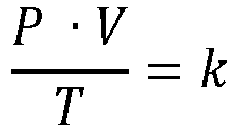
- Computer software, comprising computer executable code that enables a computer, with the code loaded in the memory of the computer, to execute the method according to claim 8.
- Method of controlling operation of an internal combustion engine (930) comprising a crank shaft and a cylinder (5), the method comprising:- Providing a combustible mixture in the cylinder (5), wherein the combustible mixture comprises at least oxygen and a first combustible at a first mixture ratio;- Obtaining an annular position of the crank shaft;- Triggering combustion of the combustible mixture at a desired first annular position of the crank shaft;- Obtaining a temperature of the combustible mixture in the cylinder during combustion using the method according to claim 8;- Comparing the temperature to a pre-determined temperature range;- If the temperature if outside of the pre-determined range, adjust at least one of:- the first mixture ratio; and- desired first annular position of the crank shaft at which the ignition of the combustible mixture is triggered.
- Method according to claim 10, further comprising at least one of:- delaying triggering of the combustion in a subsequent combustion stroke if the obtained temperature is above the pre-determined temperature range; and- bringing forward triggering of the combustion in a subsequent combustion stroke if the obtained temperature is below the pre-determined temperature range.
Applications Claiming Priority (2)
| Application Number | Priority Date | Filing Date | Title |
|---|---|---|---|
| NL1042133 | 2016-11-07 | ||
| PCT/NL2017/050717 WO2018084711A2 (en) | 2016-11-07 | 2017-11-07 | Combustion pressure sensor and its assembly in an engine component of an internal combustion engine |
Publications (2)
| Publication Number | Publication Date |
|---|---|
| EP3535556A2 EP3535556A2 (en) | 2019-09-11 |
| EP3535556B1 true EP3535556B1 (en) | 2021-07-07 |
Family
ID=60888570
Family Applications (1)
| Application Number | Title | Priority Date | Filing Date |
|---|---|---|---|
| EP17822797.1A Active EP3535556B1 (en) | 2016-11-07 | 2017-11-07 | Combustion pressure sensor and its assembly in an engine component of an internal combustion engine |
Country Status (4)
| Country | Link |
|---|---|
| EP (1) | EP3535556B1 (en) |
| JP (1) | JP6938654B2 (en) |
| CN (2) | CN112412624A (en) |
| WO (1) | WO2018084711A2 (en) |
Families Citing this family (2)
| Publication number | Priority date | Publication date | Assignee | Title |
|---|---|---|---|---|
| CN113203572B (en) * | 2021-04-16 | 2022-04-12 | 清华大学 | Experimental device and method based on rapid compressor |
| CN113915010B (en) * | 2021-11-11 | 2024-01-30 | 西安热工研究院有限公司 | Diesel engine combustion control system with triple redundancy function |
Family Cites Families (26)
| Publication number | Priority date | Publication date | Assignee | Title |
|---|---|---|---|---|
| GB1593852A (en) * | 1976-11-05 | 1981-07-22 | Burmah Oil Trading Ltd | Compression-ignition engines |
| US5150300A (en) * | 1989-02-23 | 1992-09-22 | Mitsubishi Jidosha Kogyo K.K. | Ignition timing controller for spark-ignition internal combustion engine using estimated cylinder wall temperature |
| JPH0481575A (en) * | 1990-07-20 | 1992-03-16 | Mitsubishi Motors Corp | Ignition timing control method of spark ignition internal combustion engine |
| US5146083A (en) * | 1990-09-21 | 1992-09-08 | The United States Of America As Represented By The Administrator Of The National Aeronautics And Space Administration | High temperature fiber optic microphone having a pressure-sensing reflective membrane under tensile stress |
| JP2751626B2 (en) * | 1990-11-19 | 1998-05-18 | トヨタ自動車株式会社 | In-cylinder direct injection spark ignition engine |
| US6131465A (en) | 1993-07-01 | 2000-10-17 | Wlodarczyk; Marek T. | Fiber optic combustion pressure sensors for engine knock and misfire detection |
| DE69733279T2 (en) * | 1997-02-06 | 2006-01-19 | Optrand, Inc., Plymouth | FUEL INJECTION UNITS WITH INTEGRATED FIBER OPTICAL PRESSURE SENSORS AND ASSOCIATED COMPENSATION AND MONITORING DEVICES |
| RU2152601C1 (en) * | 1998-06-16 | 2000-07-10 | Научный центр волоконной оптики при Институте общей физики РАН | Fiber-optic pressure transducer (design versions) and its manufacturing process |
| CA2398146C (en) * | 2000-02-11 | 2009-09-22 | Westport Research Inc. | Method and apparatus for gaseous fuel introduction and controlling combustion in an internal combustion engine |
| US6810320B2 (en) * | 2001-03-30 | 2004-10-26 | Mitsubishi Heavy Industries, Ltd. | Apparatus and method of combustion diagnosis/control in internal combustion engine |
| DE10225934B4 (en) * | 2002-06-11 | 2010-08-19 | Robert Bosch Gmbh | Fiber optic pressure sensor |
| JP4472932B2 (en) * | 2003-02-07 | 2010-06-02 | いすゞ自動車株式会社 | Engine combustion control device |
| JP3975936B2 (en) * | 2003-02-17 | 2007-09-12 | 日産自動車株式会社 | Knocking index value calculation device |
| US7007661B2 (en) * | 2004-01-27 | 2006-03-07 | Woodward Governor Company | Method and apparatus for controlling micro pilot fuel injection to minimize NOx and UHC emissions |
| US6994072B2 (en) * | 2004-07-12 | 2006-02-07 | General Motors Corporation | Method for mid load operation of auto-ignition combustion |
| JP2006046084A (en) * | 2004-07-30 | 2006-02-16 | Toyota Motor Corp | Ignition timing control device for internal combustion engine |
| JP4643967B2 (en) * | 2004-10-15 | 2011-03-02 | 日産自動車株式会社 | In-cylinder direct injection spark ignition internal combustion engine controller |
| CN100507484C (en) * | 2005-09-20 | 2009-07-01 | 山东省科学院激光研究所 | High performance fiber optic pressure sensor |
| EP2095084A2 (en) * | 2006-11-27 | 2009-09-02 | Kistler Holding AG | Optical pressure sensor having at least two optical fibers |
| JP2012041902A (en) * | 2010-08-23 | 2012-03-01 | Denso Corp | Control device for internal combustion engine |
| CN102147311A (en) * | 2010-12-29 | 2011-08-10 | 杭州光佑科技有限公司 | Fiber bragg grating (FBG) baroceptor |
| CN202024852U (en) * | 2010-12-29 | 2011-11-02 | 杭州光佑科技有限公司 | Fiber grating air pressure sensor |
| CN102721492B (en) * | 2012-05-31 | 2014-04-02 | 天津大学 | Optical fiber Fabry-Perot pressure sensor with fiber bragg grating temperature compensation and making method thereof |
| CN203365029U (en) * | 2013-06-28 | 2013-12-25 | 武汉理工大学 | Internal combustion engine main bearing internal surface strain and temperature monitoring system based on fiber grating |
| US9863346B2 (en) * | 2014-10-03 | 2018-01-09 | GM Global Technology Operations LLC | Method and apparatus for estimating nitrogen oxides out of an engine |
| AT516320B1 (en) * | 2014-10-06 | 2016-07-15 | Ge Jenbacher Gmbh & Co Og | Method for operating an auto-ignition internal combustion engine |
-
2017
- 2017-11-07 CN CN202011301486.4A patent/CN112412624A/en active Pending
- 2017-11-07 JP JP2019545232A patent/JP6938654B2/en active Active
- 2017-11-07 EP EP17822797.1A patent/EP3535556B1/en active Active
- 2017-11-07 CN CN201780081563.XA patent/CN110121637B/en active Active
- 2017-11-07 WO PCT/NL2017/050717 patent/WO2018084711A2/en not_active Ceased
Non-Patent Citations (1)
| Title |
|---|
| None * |
Also Published As
| Publication number | Publication date |
|---|---|
| CN110121637B (en) | 2022-07-12 |
| CN112412624A (en) | 2021-02-26 |
| JP2019537034A (en) | 2019-12-19 |
| WO2018084711A3 (en) | 2018-06-14 |
| WO2018084711A4 (en) | 2018-08-02 |
| CN110121637A (en) | 2019-08-13 |
| EP3535556A2 (en) | 2019-09-11 |
| JP6938654B2 (en) | 2021-09-22 |
| WO2018084711A2 (en) | 2018-05-11 |
Similar Documents
| Publication | Publication Date | Title |
|---|---|---|
| US7954382B2 (en) | Pressure-measuring device | |
| US6668630B1 (en) | Device for monitoring the combustion process in internal combustion engines | |
| EP1015855B1 (en) | Fuel injectors with integral fiber optic pressure sensors and associated compensation and status monitoring devices | |
| US7765856B2 (en) | Monitoring of a flame existence and a flame temperature | |
| EP3535556B1 (en) | Combustion pressure sensor and its assembly in an engine component of an internal combustion engine | |
| JP2018072326A (en) | Thermographic temperature sensor | |
| EP0419553A1 (en) | Method of operating an engine and measuring certain engine parameters | |
| Gupta et al. | On use of CO2∗ chemiluminescence for combustion metrics in natural gas fired reciprocating engines | |
| JPH07306109A (en) | Optical fiber cylinder pressure sensor and engine control system using the sensor | |
| JP3784768B2 (en) | Gas concentration sensor | |
| Richardson et al. | Misfire, knock and NOx mapping of a laser spark ignited single cylinder lean burn natural gas engine | |
| Kawahara et al. | Cycle-resolved residual gas concentration measurement inside a heavy-duty diesel engine using infrared laser absorption | |
| Hamamoto et al. | Temperature measurement of end gas under knocking condition in a spark-igniyion engine by laser interferometry | |
| JP3603341B2 (en) | In-cylinder state detection device for internal combustion engine | |
| Hartman et al. | Diesel smoke measurement and control using an in-cylinder optical sensor | |
| JP4493075B2 (en) | Gas concentration detection device for internal combustion engine | |
| Nishiyama et al. | In-situ fuel concentration measurement near spark plug by 3.392 μm infrared absorption method-application to spark ignition engine | |
| Hall et al. | Fiber optic sensor for crank angle resolved measurements of burned gas residual fraction in the cylinder of an SI engine | |
| Davis et al. | Evaluation of Cylinder Pressure Transducer Performance Including the Influence of Mounting Location and Thermal Protection | |
| JP7428462B2 (en) | Engine high temperature measurement device | |
| JP6317277B2 (en) | Fuel gas concentration measuring device for internal combustion engine | |
| Ohyama et al. | Study on Optical Combustion Sensor for Spark Ignition Engine | |
| JP2008045496A (en) | Laser ignition device with built-in optical sensor | |
| SU616553A1 (en) | Device for measuring local temperatures dependent on heat transfer | |
| JPH09229807A (en) | Pressure detector |
Legal Events
| Date | Code | Title | Description |
|---|---|---|---|
| STAA | Information on the status of an ep patent application or granted ep patent |
Free format text: STATUS: UNKNOWN |
|
| STAA | Information on the status of an ep patent application or granted ep patent |
Free format text: STATUS: THE INTERNATIONAL PUBLICATION HAS BEEN MADE |
|
| PUAI | Public reference made under article 153(3) epc to a published international application that has entered the european phase |
Free format text: ORIGINAL CODE: 0009012 |
|
| STAA | Information on the status of an ep patent application or granted ep patent |
Free format text: STATUS: REQUEST FOR EXAMINATION WAS MADE |
|
| 17P | Request for examination filed |
Effective date: 20190607 |
|
| AK | Designated contracting states |
Kind code of ref document: A2 Designated state(s): AL AT BE BG CH CY CZ DE DK EE ES FI FR GB GR HR HU IE IS IT LI LT LU LV MC MK MT NL NO PL PT RO RS SE SI SK SM TR |
|
| AX | Request for extension of the european patent |
Extension state: BA ME |
|
| DAV | Request for validation of the european patent (deleted) | ||
| DAX | Request for extension of the european patent (deleted) | ||
| STAA | Information on the status of an ep patent application or granted ep patent |
Free format text: STATUS: EXAMINATION IS IN PROGRESS |
|
| 17Q | First examination report despatched |
Effective date: 20200923 |
|
| REG | Reference to a national code |
Ref country code: DE Ref legal event code: R079 Ref document number: 602017041813 Country of ref document: DE Free format text: PREVIOUS MAIN CLASS: G01L0009000000 Ipc: F02D0035020000 |
|
| RIC1 | Information provided on ipc code assigned before grant |
Ipc: G01L 11/02 20060101ALI20201201BHEP Ipc: G01L 23/06 20060101ALI20201201BHEP Ipc: G01M 15/08 20060101ALI20201201BHEP Ipc: F02D 35/02 20060101AFI20201201BHEP Ipc: G01L 9/00 20060101ALI20201201BHEP |
|
| GRAP | Despatch of communication of intention to grant a patent |
Free format text: ORIGINAL CODE: EPIDOSNIGR1 |
|
| STAA | Information on the status of an ep patent application or granted ep patent |
Free format text: STATUS: GRANT OF PATENT IS INTENDED |
|
| INTG | Intention to grant announced |
Effective date: 20210126 |
|
| GRAS | Grant fee paid |
Free format text: ORIGINAL CODE: EPIDOSNIGR3 |
|
| GRAA | (expected) grant |
Free format text: ORIGINAL CODE: 0009210 |
|
| STAA | Information on the status of an ep patent application or granted ep patent |
Free format text: STATUS: THE PATENT HAS BEEN GRANTED |
|
| AK | Designated contracting states |
Kind code of ref document: B1 Designated state(s): AL AT BE BG CH CY CZ DE DK EE ES FI FR GB GR HR HU IE IS IT LI LT LU LV MC MK MT NL NO PL PT RO RS SE SI SK SM TR |
|
| REG | Reference to a national code |
Ref country code: GB Ref legal event code: FG4D |
|
| REG | Reference to a national code |
Ref country code: AT Ref legal event code: REF Ref document number: 1408807 Country of ref document: AT Kind code of ref document: T Effective date: 20210715 |
|
| REG | Reference to a national code |
Ref country code: DE Ref legal event code: R096 Ref document number: 602017041813 Country of ref document: DE |
|
| REG | Reference to a national code |
Ref country code: IE Ref legal event code: FG4D |
|
| REG | Reference to a national code |
Ref country code: LT Ref legal event code: MG9D |
|
| REG | Reference to a national code |
Ref country code: NL Ref legal event code: MP Effective date: 20210707 |
|
| REG | Reference to a national code |
Ref country code: AT Ref legal event code: MK05 Ref document number: 1408807 Country of ref document: AT Kind code of ref document: T Effective date: 20210707 |
|
| PG25 | Lapsed in a contracting state [announced via postgrant information from national office to epo] |
Ref country code: SE Free format text: LAPSE BECAUSE OF FAILURE TO SUBMIT A TRANSLATION OF THE DESCRIPTION OR TO PAY THE FEE WITHIN THE PRESCRIBED TIME-LIMIT Effective date: 20210707 Ref country code: RS Free format text: LAPSE BECAUSE OF FAILURE TO SUBMIT A TRANSLATION OF THE DESCRIPTION OR TO PAY THE FEE WITHIN THE PRESCRIBED TIME-LIMIT Effective date: 20210707 Ref country code: HR Free format text: LAPSE BECAUSE OF FAILURE TO SUBMIT A TRANSLATION OF THE DESCRIPTION OR TO PAY THE FEE WITHIN THE PRESCRIBED TIME-LIMIT Effective date: 20210707 Ref country code: ES Free format text: LAPSE BECAUSE OF FAILURE TO SUBMIT A TRANSLATION OF THE DESCRIPTION OR TO PAY THE FEE WITHIN THE PRESCRIBED TIME-LIMIT Effective date: 20210707 Ref country code: FI Free format text: LAPSE BECAUSE OF FAILURE TO SUBMIT A TRANSLATION OF THE DESCRIPTION OR TO PAY THE FEE WITHIN THE PRESCRIBED TIME-LIMIT Effective date: 20210707 Ref country code: AT Free format text: LAPSE BECAUSE OF FAILURE TO SUBMIT A TRANSLATION OF THE DESCRIPTION OR TO PAY THE FEE WITHIN THE PRESCRIBED TIME-LIMIT Effective date: 20210707 Ref country code: BG Free format text: LAPSE BECAUSE OF FAILURE TO SUBMIT A TRANSLATION OF THE DESCRIPTION OR TO PAY THE FEE WITHIN THE PRESCRIBED TIME-LIMIT Effective date: 20211007 Ref country code: LT Free format text: LAPSE BECAUSE OF FAILURE TO SUBMIT A TRANSLATION OF THE DESCRIPTION OR TO PAY THE FEE WITHIN THE PRESCRIBED TIME-LIMIT Effective date: 20210707 Ref country code: PT Free format text: LAPSE BECAUSE OF FAILURE TO SUBMIT A TRANSLATION OF THE DESCRIPTION OR TO PAY THE FEE WITHIN THE PRESCRIBED TIME-LIMIT Effective date: 20211108 Ref country code: NO Free format text: LAPSE BECAUSE OF FAILURE TO SUBMIT A TRANSLATION OF THE DESCRIPTION OR TO PAY THE FEE WITHIN THE PRESCRIBED TIME-LIMIT Effective date: 20211007 Ref country code: NL Free format text: LAPSE BECAUSE OF FAILURE TO SUBMIT A TRANSLATION OF THE DESCRIPTION OR TO PAY THE FEE WITHIN THE PRESCRIBED TIME-LIMIT Effective date: 20210707 |
|
| PG25 | Lapsed in a contracting state [announced via postgrant information from national office to epo] |
Ref country code: PL Free format text: LAPSE BECAUSE OF FAILURE TO SUBMIT A TRANSLATION OF THE DESCRIPTION OR TO PAY THE FEE WITHIN THE PRESCRIBED TIME-LIMIT Effective date: 20210707 Ref country code: LV Free format text: LAPSE BECAUSE OF FAILURE TO SUBMIT A TRANSLATION OF THE DESCRIPTION OR TO PAY THE FEE WITHIN THE PRESCRIBED TIME-LIMIT Effective date: 20210707 Ref country code: GR Free format text: LAPSE BECAUSE OF FAILURE TO SUBMIT A TRANSLATION OF THE DESCRIPTION OR TO PAY THE FEE WITHIN THE PRESCRIBED TIME-LIMIT Effective date: 20211008 |
|
| REG | Reference to a national code |
Ref country code: DE Ref legal event code: R097 Ref document number: 602017041813 Country of ref document: DE |
|
| PG25 | Lapsed in a contracting state [announced via postgrant information from national office to epo] |
Ref country code: DK Free format text: LAPSE BECAUSE OF FAILURE TO SUBMIT A TRANSLATION OF THE DESCRIPTION OR TO PAY THE FEE WITHIN THE PRESCRIBED TIME-LIMIT Effective date: 20210707 |
|
| PLBE | No opposition filed within time limit |
Free format text: ORIGINAL CODE: 0009261 |
|
| STAA | Information on the status of an ep patent application or granted ep patent |
Free format text: STATUS: NO OPPOSITION FILED WITHIN TIME LIMIT |
|
| PG25 | Lapsed in a contracting state [announced via postgrant information from national office to epo] |
Ref country code: SM Free format text: LAPSE BECAUSE OF FAILURE TO SUBMIT A TRANSLATION OF THE DESCRIPTION OR TO PAY THE FEE WITHIN THE PRESCRIBED TIME-LIMIT Effective date: 20210707 Ref country code: SK Free format text: LAPSE BECAUSE OF FAILURE TO SUBMIT A TRANSLATION OF THE DESCRIPTION OR TO PAY THE FEE WITHIN THE PRESCRIBED TIME-LIMIT Effective date: 20210707 Ref country code: RO Free format text: LAPSE BECAUSE OF FAILURE TO SUBMIT A TRANSLATION OF THE DESCRIPTION OR TO PAY THE FEE WITHIN THE PRESCRIBED TIME-LIMIT Effective date: 20210707 Ref country code: EE Free format text: LAPSE BECAUSE OF FAILURE TO SUBMIT A TRANSLATION OF THE DESCRIPTION OR TO PAY THE FEE WITHIN THE PRESCRIBED TIME-LIMIT Effective date: 20210707 Ref country code: CZ Free format text: LAPSE BECAUSE OF FAILURE TO SUBMIT A TRANSLATION OF THE DESCRIPTION OR TO PAY THE FEE WITHIN THE PRESCRIBED TIME-LIMIT Effective date: 20210707 Ref country code: AL Free format text: LAPSE BECAUSE OF FAILURE TO SUBMIT A TRANSLATION OF THE DESCRIPTION OR TO PAY THE FEE WITHIN THE PRESCRIBED TIME-LIMIT Effective date: 20210707 |
|
| 26N | No opposition filed |
Effective date: 20220408 |
|
| PG25 | Lapsed in a contracting state [announced via postgrant information from national office to epo] |
Ref country code: MC Free format text: LAPSE BECAUSE OF FAILURE TO SUBMIT A TRANSLATION OF THE DESCRIPTION OR TO PAY THE FEE WITHIN THE PRESCRIBED TIME-LIMIT Effective date: 20210707 |
|
| REG | Reference to a national code |
Ref country code: CH Ref legal event code: PL |
|
| PG25 | Lapsed in a contracting state [announced via postgrant information from national office to epo] |
Ref country code: LU Free format text: LAPSE BECAUSE OF NON-PAYMENT OF DUE FEES Effective date: 20211107 Ref country code: BE Free format text: LAPSE BECAUSE OF NON-PAYMENT OF DUE FEES Effective date: 20211130 |
|
| REG | Reference to a national code |
Ref country code: BE Ref legal event code: MM Effective date: 20211130 |
|
| PG25 | Lapsed in a contracting state [announced via postgrant information from national office to epo] |
Ref country code: LI Free format text: LAPSE BECAUSE OF NON-PAYMENT OF DUE FEES Effective date: 20211130 Ref country code: CH Free format text: LAPSE BECAUSE OF NON-PAYMENT OF DUE FEES Effective date: 20211130 |
|
| PG25 | Lapsed in a contracting state [announced via postgrant information from national office to epo] |
Ref country code: IE Free format text: LAPSE BECAUSE OF NON-PAYMENT OF DUE FEES Effective date: 20211107 |
|
| PG25 | Lapsed in a contracting state [announced via postgrant information from national office to epo] |
Ref country code: CY Free format text: LAPSE BECAUSE OF FAILURE TO SUBMIT A TRANSLATION OF THE DESCRIPTION OR TO PAY THE FEE WITHIN THE PRESCRIBED TIME-LIMIT Effective date: 20210707 |
|
| PG25 | Lapsed in a contracting state [announced via postgrant information from national office to epo] |
Ref country code: HU Free format text: LAPSE BECAUSE OF FAILURE TO SUBMIT A TRANSLATION OF THE DESCRIPTION OR TO PAY THE FEE WITHIN THE PRESCRIBED TIME-LIMIT; INVALID AB INITIO Effective date: 20171107 |
|
| PG25 | Lapsed in a contracting state [announced via postgrant information from national office to epo] |
Ref country code: MK Free format text: LAPSE BECAUSE OF FAILURE TO SUBMIT A TRANSLATION OF THE DESCRIPTION OR TO PAY THE FEE WITHIN THE PRESCRIBED TIME-LIMIT Effective date: 20210707 |
|
| PG25 | Lapsed in a contracting state [announced via postgrant information from national office to epo] |
Ref country code: TR Free format text: LAPSE BECAUSE OF FAILURE TO SUBMIT A TRANSLATION OF THE DESCRIPTION OR TO PAY THE FEE WITHIN THE PRESCRIBED TIME-LIMIT Effective date: 20210707 |
|
| PG25 | Lapsed in a contracting state [announced via postgrant information from national office to epo] |
Ref country code: MT Free format text: LAPSE BECAUSE OF FAILURE TO SUBMIT A TRANSLATION OF THE DESCRIPTION OR TO PAY THE FEE WITHIN THE PRESCRIBED TIME-LIMIT Effective date: 20210707 |
|
| PGFP | Annual fee paid to national office [announced via postgrant information from national office to epo] |
Ref country code: GB Payment date: 20250910 Year of fee payment: 9 |
|
| PGFP | Annual fee paid to national office [announced via postgrant information from national office to epo] |
Ref country code: DE Payment date: 20250910 Year of fee payment: 9 |
|
| PGFP | Annual fee paid to national office [announced via postgrant information from national office to epo] |
Ref country code: IT Payment date: 20250910 Year of fee payment: 9 |
|
| PGFP | Annual fee paid to national office [announced via postgrant information from national office to epo] |
Ref country code: FR Payment date: 20251128 Year of fee payment: 9 |