EP3535169B1 - Brake assist system for a cyclist on a bicycle - Google Patents
Brake assist system for a cyclist on a bicycle Download PDFInfo
- Publication number
- EP3535169B1 EP3535169B1 EP17801504.6A EP17801504A EP3535169B1 EP 3535169 B1 EP3535169 B1 EP 3535169B1 EP 17801504 A EP17801504 A EP 17801504A EP 3535169 B1 EP3535169 B1 EP 3535169B1
- Authority
- EP
- European Patent Office
- Prior art keywords
- front wheel
- actuator
- bicycle
- deceleration
- force
- Prior art date
- Legal status (The legal status is an assumption and is not a legal conclusion. Google has not performed a legal analysis and makes no representation as to the accuracy of the status listed.)
- Active
Links
Images

Classifications
-
- B—PERFORMING OPERATIONS; TRANSPORTING
- B60—VEHICLES IN GENERAL
- B60T—VEHICLE BRAKE CONTROL SYSTEMS OR PARTS THEREOF; BRAKE CONTROL SYSTEMS OR PARTS THEREOF, IN GENERAL; ARRANGEMENT OF BRAKING ELEMENTS ON VEHICLES IN GENERAL; PORTABLE DEVICES FOR PREVENTING UNWANTED MOVEMENT OF VEHICLES; VEHICLE MODIFICATIONS TO FACILITATE COOLING OF BRAKES
- B60T8/00—Arrangements for adjusting wheel-braking force to meet varying vehicular or ground-surface conditions, e.g. limiting or varying distribution of braking force
- B60T8/17—Using electrical or electronic regulation means to control braking
- B60T8/1701—Braking or traction control means specially adapted for particular types of vehicles
- B60T8/1706—Braking or traction control means specially adapted for particular types of vehicles for single-track vehicles, e.g. motorcycles
-
- B—PERFORMING OPERATIONS; TRANSPORTING
- B60—VEHICLES IN GENERAL
- B60T—VEHICLE BRAKE CONTROL SYSTEMS OR PARTS THEREOF; BRAKE CONTROL SYSTEMS OR PARTS THEREOF, IN GENERAL; ARRANGEMENT OF BRAKING ELEMENTS ON VEHICLES IN GENERAL; PORTABLE DEVICES FOR PREVENTING UNWANTED MOVEMENT OF VEHICLES; VEHICLE MODIFICATIONS TO FACILITATE COOLING OF BRAKES
- B60T8/00—Arrangements for adjusting wheel-braking force to meet varying vehicular or ground-surface conditions, e.g. limiting or varying distribution of braking force
- B60T8/32—Arrangements for adjusting wheel-braking force to meet varying vehicular or ground-surface conditions, e.g. limiting or varying distribution of braking force responsive to a speed condition, e.g. acceleration or deceleration
- B60T8/321—Arrangements for adjusting wheel-braking force to meet varying vehicular or ground-surface conditions, e.g. limiting or varying distribution of braking force responsive to a speed condition, e.g. acceleration or deceleration deceleration
- B60T8/3225—Systems specially adapted for single-track vehicles, e.g. motorcycles
-
- B—PERFORMING OPERATIONS; TRANSPORTING
- B60—VEHICLES IN GENERAL
- B60T—VEHICLE BRAKE CONTROL SYSTEMS OR PARTS THEREOF; BRAKE CONTROL SYSTEMS OR PARTS THEREOF, IN GENERAL; ARRANGEMENT OF BRAKING ELEMENTS ON VEHICLES IN GENERAL; PORTABLE DEVICES FOR PREVENTING UNWANTED MOVEMENT OF VEHICLES; VEHICLE MODIFICATIONS TO FACILITATE COOLING OF BRAKES
- B60T11/00—Transmitting braking action from initiating means to ultimate brake actuator without power assistance or drive or where such assistance or drive is irrelevant
- B60T11/10—Transmitting braking action from initiating means to ultimate brake actuator without power assistance or drive or where such assistance or drive is irrelevant transmitting by fluid means, e.g. hydraulic
- B60T11/16—Master control, e.g. master cylinders
- B60T11/165—Single master cylinders for pressurised systems
-
- B—PERFORMING OPERATIONS; TRANSPORTING
- B60—VEHICLES IN GENERAL
- B60T—VEHICLE BRAKE CONTROL SYSTEMS OR PARTS THEREOF; BRAKE CONTROL SYSTEMS OR PARTS THEREOF, IN GENERAL; ARRANGEMENT OF BRAKING ELEMENTS ON VEHICLES IN GENERAL; PORTABLE DEVICES FOR PREVENTING UNWANTED MOVEMENT OF VEHICLES; VEHICLE MODIFICATIONS TO FACILITATE COOLING OF BRAKES
- B60T7/00—Brake-action initiating means
- B60T7/02—Brake-action initiating means for personal initiation
- B60T7/08—Brake-action initiating means for personal initiation hand actuated
- B60T7/085—Brake-action initiating means for personal initiation hand actuated by electrical means, e.g. travel, force sensors
-
- B—PERFORMING OPERATIONS; TRANSPORTING
- B60—VEHICLES IN GENERAL
- B60T—VEHICLE BRAKE CONTROL SYSTEMS OR PARTS THEREOF; BRAKE CONTROL SYSTEMS OR PARTS THEREOF, IN GENERAL; ARRANGEMENT OF BRAKING ELEMENTS ON VEHICLES IN GENERAL; PORTABLE DEVICES FOR PREVENTING UNWANTED MOVEMENT OF VEHICLES; VEHICLE MODIFICATIONS TO FACILITATE COOLING OF BRAKES
- B60T7/00—Brake-action initiating means
- B60T7/02—Brake-action initiating means for personal initiation
- B60T7/08—Brake-action initiating means for personal initiation hand actuated
- B60T7/10—Disposition of hand control
- B60T7/102—Disposition of hand control by means of a tilting lever
- B60T7/104—Disposition of hand control by means of a tilting lever with a locking mechanism
-
- B—PERFORMING OPERATIONS; TRANSPORTING
- B60—VEHICLES IN GENERAL
- B60T—VEHICLE BRAKE CONTROL SYSTEMS OR PARTS THEREOF; BRAKE CONTROL SYSTEMS OR PARTS THEREOF, IN GENERAL; ARRANGEMENT OF BRAKING ELEMENTS ON VEHICLES IN GENERAL; PORTABLE DEVICES FOR PREVENTING UNWANTED MOVEMENT OF VEHICLES; VEHICLE MODIFICATIONS TO FACILITATE COOLING OF BRAKES
- B60T8/00—Arrangements for adjusting wheel-braking force to meet varying vehicular or ground-surface conditions, e.g. limiting or varying distribution of braking force
- B60T8/32—Arrangements for adjusting wheel-braking force to meet varying vehicular or ground-surface conditions, e.g. limiting or varying distribution of braking force responsive to a speed condition, e.g. acceleration or deceleration
- B60T8/58—Arrangements for adjusting wheel-braking force to meet varying vehicular or ground-surface conditions, e.g. limiting or varying distribution of braking force responsive to a speed condition, e.g. acceleration or deceleration responsive to speed and another condition or to plural speed conditions
-
- B—PERFORMING OPERATIONS; TRANSPORTING
- B60—VEHICLES IN GENERAL
- B60T—VEHICLE BRAKE CONTROL SYSTEMS OR PARTS THEREOF; BRAKE CONTROL SYSTEMS OR PARTS THEREOF, IN GENERAL; ARRANGEMENT OF BRAKING ELEMENTS ON VEHICLES IN GENERAL; PORTABLE DEVICES FOR PREVENTING UNWANTED MOVEMENT OF VEHICLES; VEHICLE MODIFICATIONS TO FACILITATE COOLING OF BRAKES
- B60T8/00—Arrangements for adjusting wheel-braking force to meet varying vehicular or ground-surface conditions, e.g. limiting or varying distribution of braking force
- B60T8/32—Arrangements for adjusting wheel-braking force to meet varying vehicular or ground-surface conditions, e.g. limiting or varying distribution of braking force responsive to a speed condition, e.g. acceleration or deceleration
- B60T8/72—Arrangements for adjusting wheel-braking force to meet varying vehicular or ground-surface conditions, e.g. limiting or varying distribution of braking force responsive to a speed condition, e.g. acceleration or deceleration responsive to a difference between a speed condition, e.g. deceleration, and a fixed reference
- B60T8/74—Arrangements for adjusting wheel-braking force to meet varying vehicular or ground-surface conditions, e.g. limiting or varying distribution of braking force responsive to a speed condition, e.g. acceleration or deceleration responsive to a difference between a speed condition, e.g. deceleration, and a fixed reference sensing a rate of change of velocity
-
- B—PERFORMING OPERATIONS; TRANSPORTING
- B60—VEHICLES IN GENERAL
- B60T—VEHICLE BRAKE CONTROL SYSTEMS OR PARTS THEREOF; BRAKE CONTROL SYSTEMS OR PARTS THEREOF, IN GENERAL; ARRANGEMENT OF BRAKING ELEMENTS ON VEHICLES IN GENERAL; PORTABLE DEVICES FOR PREVENTING UNWANTED MOVEMENT OF VEHICLES; VEHICLE MODIFICATIONS TO FACILITATE COOLING OF BRAKES
- B60T8/00—Arrangements for adjusting wheel-braking force to meet varying vehicular or ground-surface conditions, e.g. limiting or varying distribution of braking force
- B60T8/32—Arrangements for adjusting wheel-braking force to meet varying vehicular or ground-surface conditions, e.g. limiting or varying distribution of braking force responsive to a speed condition, e.g. acceleration or deceleration
- B60T8/72—Arrangements for adjusting wheel-braking force to meet varying vehicular or ground-surface conditions, e.g. limiting or varying distribution of braking force responsive to a speed condition, e.g. acceleration or deceleration responsive to a difference between a speed condition, e.g. deceleration, and a fixed reference
- B60T8/76—Arrangements for adjusting wheel-braking force to meet varying vehicular or ground-surface conditions, e.g. limiting or varying distribution of braking force responsive to a speed condition, e.g. acceleration or deceleration responsive to a difference between a speed condition, e.g. deceleration, and a fixed reference two or more sensing means from different wheels indicative of the same type of speed condition
-
- B—PERFORMING OPERATIONS; TRANSPORTING
- B62—LAND VEHICLES FOR TRAVELLING OTHERWISE THAN ON RAILS
- B62L—BRAKES SPECIALLY ADAPTED FOR CYCLES
- B62L1/00—Brakes; Arrangements thereof
- B62L1/02—Brakes; Arrangements thereof in which cycle wheels are engaged by brake elements
- B62L1/06—Brakes; Arrangements thereof in which cycle wheels are engaged by brake elements the wheel rim being engaged
-
- B—PERFORMING OPERATIONS; TRANSPORTING
- B62—LAND VEHICLES FOR TRAVELLING OTHERWISE THAN ON RAILS
- B62L—BRAKES SPECIALLY ADAPTED FOR CYCLES
- B62L3/00—Brake-actuating mechanisms; Arrangements thereof
- B62L3/02—Brake-actuating mechanisms; Arrangements thereof for control by a hand lever
-
- B—PERFORMING OPERATIONS; TRANSPORTING
- B62—LAND VEHICLES FOR TRAVELLING OTHERWISE THAN ON RAILS
- B62L—BRAKES SPECIALLY ADAPTED FOR CYCLES
- B62L3/00—Brake-actuating mechanisms; Arrangements thereof
- B62L3/02—Brake-actuating mechanisms; Arrangements thereof for control by a hand lever
- B62L3/023—Brake-actuating mechanisms; Arrangements thereof for control by a hand lever acting on fluid pressure systems
-
- B—PERFORMING OPERATIONS; TRANSPORTING
- B60—VEHICLES IN GENERAL
- B60T—VEHICLE BRAKE CONTROL SYSTEMS OR PARTS THEREOF; BRAKE CONTROL SYSTEMS OR PARTS THEREOF, IN GENERAL; ARRANGEMENT OF BRAKING ELEMENTS ON VEHICLES IN GENERAL; PORTABLE DEVICES FOR PREVENTING UNWANTED MOVEMENT OF VEHICLES; VEHICLE MODIFICATIONS TO FACILITATE COOLING OF BRAKES
- B60T2230/00—Monitoring, detecting special vehicle behaviour; Counteracting thereof
- B60T2230/03—Overturn, rollover
-
- B—PERFORMING OPERATIONS; TRANSPORTING
- B60—VEHICLES IN GENERAL
- B60T—VEHICLE BRAKE CONTROL SYSTEMS OR PARTS THEREOF; BRAKE CONTROL SYSTEMS OR PARTS THEREOF, IN GENERAL; ARRANGEMENT OF BRAKING ELEMENTS ON VEHICLES IN GENERAL; PORTABLE DEVICES FOR PREVENTING UNWANTED MOVEMENT OF VEHICLES; VEHICLE MODIFICATIONS TO FACILITATE COOLING OF BRAKES
- B60T2240/00—Monitoring, detecting wheel/tyre behaviour; counteracting thereof
-
- B—PERFORMING OPERATIONS; TRANSPORTING
- B60—VEHICLES IN GENERAL
- B60T—VEHICLE BRAKE CONTROL SYSTEMS OR PARTS THEREOF; BRAKE CONTROL SYSTEMS OR PARTS THEREOF, IN GENERAL; ARRANGEMENT OF BRAKING ELEMENTS ON VEHICLES IN GENERAL; PORTABLE DEVICES FOR PREVENTING UNWANTED MOVEMENT OF VEHICLES; VEHICLE MODIFICATIONS TO FACILITATE COOLING OF BRAKES
- B60T2240/00—Monitoring, detecting wheel/tyre behaviour; counteracting thereof
- B60T2240/06—Wheel load; Wheel lift
Definitions
- the present invention refers to a brake assist system for a cyclist on a bicycle, particularly a system adapted to help the cyclist to avoid to apply on the front wheel an excessive braking force, which could lock the wheel itself or cause the bicycle to flip over.
- Braking the front wheel of a bicycle is an operation requiring a determined sensibility by the cyclist and, if this operation is not correctly performed, could cause risks and problems. Particularly, an excessively strong braking applied on the front wheel could lock the wheel itself (typically on road surfaces exhibiting a low traction, for example due to the rain), or even could cause the bicycle itself to flip over about the front wheel.
- the activating module 4" commands the actuator 3 so that this latter is activated and supplies to the controller 4' a reference deceleration ⁇ ref value equal to value of the reference deceleration ⁇ ref * supplied by the cyclist. Therefore, as soon as the deceleration ⁇ of the front wheel attains a value less than the reference deceleration ⁇ ref * (or, preferably, a value less than the reference deceleration ⁇ ref * less a fixed constant value), the activating module 4" deactivates the actuator 3 and therefore the cyclist has again a complete control on the braking.
- the cyclist it is not necessary for the cyclist to preset the reference deceleration ⁇ ref * based, for example, on the road conditions, since the reference deceleration ⁇ ref is determined by the activating module 4" as a function of detections performed during the bicycle use, which mirror the real use conditions of the same.
- the activating module 4" activates the actuator 3 and sets the reference deceleration ⁇ ref equal to a value less (preferably comprised between 80% and 95%) than the value of the deceleration ⁇ measured at the front wheel 101 when such circumstance occurs.
- the system 1 comprises, in addition to the sensor 2 for determining the angular speed ⁇ 1 of the front wheel, the beforehand cited inertial measuring unit 7 adapted to measure at least the pitch speed of the bicycle 100 and adapted to generate a signal representative of the same.
- the activating module 4" receives, as an input, such signal representative of the pitch speed ⁇ y supplied by the inertial measuring unit 7 and is further configured for estimating, from this latter, the pitch angle ⁇ of the bicycle.
- Such estimate can be obtained by per se known methods (see: M. Corno, P. Spagnol, S. M. Savaresi (2014).
- the activating module 4" can use mixed logics, in other words can simultaneously use one or more of the logics described with reference to the specific embodiments in Figures 4a-4e .
- the system 1 comprises a display (not shown in the figures) which shows to the cyclist when the actuator is activated. Further, the system 1 preferably comprises a battery 8 for supplying the actuator, sensors, control module, and the display itself.
Landscapes
- Engineering & Computer Science (AREA)
- Mechanical Engineering (AREA)
- Transportation (AREA)
- Physics & Mathematics (AREA)
- Fluid Mechanics (AREA)
- Regulating Braking Force (AREA)
Description
- The present invention refers to a brake assist system for a cyclist on a bicycle, particularly a system adapted to help the cyclist to avoid to apply on the front wheel an excessive braking force, which could lock the wheel itself or cause the bicycle to flip over.
- Braking the front wheel of a bicycle is an operation requiring a determined sensibility by the cyclist and, if this operation is not correctly performed, could cause risks and problems. Particularly, an excessively strong braking applied on the front wheel could lock the wheel itself (typically on road surfaces exhibiting a low traction, for example due to the rain), or even could cause the bicycle itself to flip over about the front wheel.
- In order to solve this problem, some brake assist systems were provided for braking systems with disk brakes actuated by hydraulic systems which actively intervene on the braking by modulating it.
- However, such systems require to design again from scratch the braking system and further they are rather expensive and heavy.
- Document
DE 10 2013 213413 A1 discloses a brake assist system according to the preamble of claim 1. - Therefore, an object of the present invention consists of making available a brake assist system which acts for preventing the front wheel from being locked or the bicycle from being flipped over, which shows a simple arrangement and requires limited changes of the braking system itself.
- This and other objects are obtained by a brake assist system for a cyclist on a bicycle, according to claim 1.
- Dependent claims define possible advantageous embodiments of the invention.
- For obtaining a better comprehension of the invention and appreciating the advantages thereof, some exemplifying non-limiting embodiments thereof will be described in the following with reference to the attached figures, wherein:
-
Figure 1 is a schematic illustration of a bicycle provided with a brake assist system according to a possible embodiment of the invention; -
Figure 2 is a block diagram of the brake assist system according to a possible embodiment of the invention; -
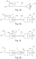
Figures 3a-3d are schematic illustrations of possible alternative braking systems for bicycles, provided with a brake assist system according to the invention; -
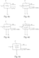
Figures 4a-4e are schematic illustrations of modules for activating the brake assist system according to possible alternative embodiments of the invention. - With reference to
Figure 1 , a bicycle is generally indicated byreference 100. Thebicycle 100 comprises afront wheel 101 and arear wheel 102. A brake, actuatable by alever 103 mounted to the handlebar, for example, is associated to thefront wheel 101. The braking system can be of any known type, for example a shoe or disk braking system, commanded by a hydraulic or mechanical system, for example by a cable. - It is made reference to
Figure 3a-3d , which schematically illustrate possible braking systems of a bicycle. -
Figure 3a represents a mechanical braking system, wherein the cyclist acts on thelever 103 by applying a force Fc which is transmitted, by means of amechanical cable 104, to abraking member 105, which is shown as a pair of shoes capable of exerting a braking force FB on thefront wheel 101, for example. - Moreover, on the other hand
Figures 3b-3d illustrate a hydraulic-type braking system, wherein the cyclist acts on thelever 103 by applying a force Fc which is transmitted to apiston 106 which pressurizes a fluid, for example oil, contained in ahydraulic transmission 109, which in turn thrusts asecond piston 108 which moves thebraking member 105 which can therefore exert the braking force FB. - An
actuator 3, which, as described in the following, interacts with the braking system itself for modifying the braking action exerted by the cyclist, is insertable in the braking systems. - The
bicycle 100 comprises a brake assist system 1 for a cyclist on the bicycle itself. The system 1, as will be described, has the main goal of preventing thefront wheel 101 from being locked or of preventing the bicycle from being flipped over due to an excessive braking force Fc applied by the cyclist to thefront wheel 101 itself. - The system 1 comprises a
sensor 2 for measuring the angular speed ω1 of thefront wheel 101. Thesensor 2 is adapted to generate a signal representing such angular speed of the wheel. According to further possible embodiments, the system 1 further comprises a sensor 6 for measuring the angular speed ω2 of therear wheel 102, adapted to generate a signal representative of such angular speed of the rear wheel, and/or an inertial measuring unit 7 adapted to measure at least the longitudinal acceleration ax and/or the pitch angular speed ωy of thebicycle 100 and adapted to generate signals representing the same. The inertial measuring unit 7 can be applied to any portions of the bicycle frame. - Moreover, the system 1 comprises the beforehand cited
actuator 3 capable of exerting an actuator force FA. Theactuator 3 is connectable to the braking system of the bicycle so that, under certain conditions which will be elucidated in the following, the actuator force FA opposes the force Fc applied by the cyclist, in order to reduce the braking force FB if this force is such to be capable of triggering a flip-over. - For example, the
actuator 3 can be applied in order to directly act on thelever 103 of the brake of thefront wheel 101, independently from the type of the braking system: mechanical (Figure 3a ) and hydraulic (Figure 3b ). As an alternative, theactuator 3 can act on thepiston 106 in order to reduce the pressure in the hydraulic circuit (Figure 3c ), or can be inserted in the hydraulic transmission itself (Figure 3d ) between thepiston 106 connected to thebrake lever 103, and thesecond piston 108 acting on thebraking member 105. In all the exemplifying illustrated variants, the actuator force FA opposes the cyclist force Fc, in order to reduce the total resultant force. Consequently, the braking force FB will be reduced. - Preferably, the
actuator 3 is electrically actuated, and can be voltage-controlled or current-controlled. Particularly, theactuator 3 is preferably of a linear type and it is possible to control the stroke x thereof, on which the actuator force FC will depend. Obviously, according to further possible embodiments, the actuator can be of a rotating-type and the controlled magnitude is the angular position thereof. - The system 1 comprises a
control module 4 adapted to activate selectively, in other words under determined specific conditions, theactuator 3 and to generate a command signal of this latter when theactuator 3 is active, so that theactuator 3, by exerting the actuator force FA, affects the braking force FB resulting from the force Fc applied by the cyclist, for reducing it, and therefore, for eliminating the slipping conditions of thefront wlieel 101 or a possible flip-over of thebicycle 100 about this latter. Particularly, thecontrol module 4 comprises a controller 4' which commands theactuator 3 based on a reference law when this is active, so that the deceleration η of the front wheel, affected by the action of theactuator 3, follows a reference deceleration ηref, and an activatingmodule 4", which selectively outputs an activating signal (conventionally indicated by 1 = activation; 0 = deactivation inFigure 2 ) to theactuator 3 when the conditions requiring its operation are verified, and determines said reference deceleration ηref. As it will be understood, the logics for activating theactuator 3 and also for determining the reference deceleration ηref can be different according to the inputs supplied to the activatingmodule 4". Thecontrol module 4 receives, as an input, the signal representative of the angular speed ω1 of thefront wheel 101 and is configured for determining, from this, a deceleration η of the front wheel itself. For example, the angular deceleration of the front wheel can be obtained by a time derivative of the angular speed measured by means of thesensor 2, while the linear deceleration of the front wheel can be determined from the angular deceleration by knowing the wheel radius. The deceleration indicated by η can represent, in the present description and in the attached claims, both the angular deceleration and the linear deceleration of the front wheel. It is observed that conventionally, in the present description and in the attached claims, it is assumed that the deceleration has a positive sign, in other words, the term deceleration will indicate the absolute value of a negative acceleration. - When the
actuator 3 is activated (by modes which will be explained in the following), thecontrol module 4, particularly the controller 4' thereof, commands theactuator 3 so that, due to the actuator force FA, the deceleration η of the front wheel decreases by following the reference deceleration ηref. In other words, the controller 4', by acting on theactuator 3, performs a control, preferably a closed-loop one (for example of a P, PI, PD, or PID type), on the deceleration η of the front wheel, wherein the desired deceleration is the reference deceleration ηref. - With reference to the exemplifying case wherein the
actuator 3 is of a linear type, thecontrol module 4 can particularly control the stroke x thereof, related to the actuator force FA. Indeed, such stroke x, in case of a cable mechanical system, entails a movement for reducing the braking force of the braking member itself, while in case of a hydraulic system, entails a reduction of the pressure of the fluid in the braking system which acts on the braking member. - According to a possible embodiment, the
control module 4 comprises a closed-loop controller 5 of the stroke x of the actuator. With reference toFigure 2 , the controller 4' of thecontrol module 4, upon a comparison between the deceleration η of the front wheel and the reference deceleration ηref, supplies the reference stroke value xref of theactuator 3, which is the stroke the actuator, based on the configuration thereof and the configuration of the braking system, should have for exerting the actuator force FA so that the deceleration η of the front wheel follows the reference deceleration ηref. Sensors measuring the effective stroke x are advantageously provided on the actuator so that the closed-loop controller 5 can execute a feedback control on the actuator stroke. For example, the closed-loop controller 5 can be of the P, PI, PD, or PID type. - Based on the stroke x determined by the closed-
loop controller 5, theactuator 3 will exert the actuator force FA thereof on the braking system, and consequently a deceleration η of the bicycle subjected to the cyclist force Fc, will be reduced in order to fall between values such to not cause the front wheel to flip over or to be locked. - Advantageously, it is observed that the
actuator 3 is configured so that the actuator force FA per se is not capable of generating the braking force FB on the front wheel in the braking system. For example, with reference to the variants inFigures 3a and 3b , theactuator 3 can only exert a force opposite to the one of the cyclist Fc on thelever 103. Therefore, the actuator force FA will be never capable of triggering a braking due to the standard structure of a brake lever. - In the same way, with reference to the variants in
Figures 3c and 3d , the actuator force FA is such to reduce the pressure in thehydraulic transmission 109, in other words theactuator 3 is never capable of acting on the pistons of the hydraulic system according to a direction which increases the pressure of the working fluid actuating thebraking member 105. - More advantageously, the
actuator 3 is configured so that the maximum value of the actuator force FA is such to be surpassed by the force Fc exerted by the cyclist on thelever 103. In other words, the cyclist, with just the force of his/her hand, must be capable of surpassing the opposite force generated by theactuator 3. In this way, dangerous conditions wherein the braking is completely prevented by the actuator, are avoided. - Now, some possible logics for activating and controlling the
actuator 3 according to possible alternative embodiments of the invention, will be described. Particularly, the following embodiments differ from each other because the activatingmodule 4" activates theactuator 3 and sets the reference deceleration ηref. - According to a possible embodiment (
Figure 4a ), the activatingmodule 4" receives, as an input, the signal representative of the angular speed ω1 of the front wheel, from which, as discussed, it is possible to obtain the deceleration η of the front wheel, and is configured for comparing the deceleration η of the front wheel with a reference deceleration ηref* supplied by the cyclist. If the deceleration η of the front wheel is less than the reference deceleration ηref* supplied by the cyclist, the activatingmodule 4" commands theactuator 3 so that this one remains deactivated, in other words does not exert any actuator force. Under such condition, the braking system substantially operates as if theactuator 3 were not present. - On the other hand, if the deceleration η of the front wheel is greater than or equal to the reference deceleration ηref* supplied by the cyclist, the activating
module 4" commands theactuator 3 so that this latter is activated and supplies to the controller 4' a reference deceleration ηref value equal to value of the reference deceleration ηref* supplied by the cyclist. Therefore, as soon as the deceleration η of the front wheel attains a value less than the reference deceleration ηref* (or, preferably, a value less than the reference deceleration ηref* less a fixed constant value), the activatingmodule 4" deactivates theactuator 3 and therefore the cyclist has again a complete control on the braking. - The reference deceleration ηref* supplied by the cyclist can have a predetermined constant value, for example, dependent on the characteristics of the bicycle and/or cyclist and/or the position of this latter. Moreover, the reference deceleration ηref* can depend on the road conditions (dry, wet), which affect the traction of the tire of the front wheel. For example, the cyclist can set this latter parameter by a user interface unit (not shown in the figures) connected to the
control module 4. According to this embodiment, the system requires only the beforehand citedsensor 2 for measuring the angular speed ω1 of the front wheel. - According to a further possible embodiment (
Figure 4b ), moreover the system 1 comprises the beforehand cited sensor 6 for measuring the angular speed ω2 of thefront wheel 102. Advantageously, the activatingmodule 4" receives, as an input, the signal representative of the angular speed ω2 of thefront wheel 102 and the signal representative of the angular speed ω1 of thefront wheel 101 and compares them. By comparing these two speeds ω1 and ω2 it is possible to obtain information about a possible flip-over of thebicycle 100 around thefront wheel 101, or about a locking of this latter with respect to the rear wheel. Indeed, if the front wheel is not flipped over or locked, the linear speeds of the front wheel (given by v1 = ω1R1, wherein R1 is the radius of the front wheel 101) and of the rear wheel (given by v2 = ω2R2, wherein R2 is the radius of the rear wheel 102) are equal, while, when the front wheel is flipped over or locked, the linear speed v2 of the rear wheel will tend to be different from, particularly greater than, the linear speed v1 of the front wheel. According to this embodiment, the activatingmodule 4" activates theactuator 3 when the linear speeds v1 and v2 measured at the two wheels, differ of at least one predetermined value v*, and is configured for automatically setting the reference deceleration ηref to a value less (preferably comprised between 80% and 95%) than the value of the deceleration η measured at thefront wheel 101 when the linear speeds v1 and v2 measured at the two wheels, differ of at least said predetermined value v*. According to this embodiment, it is not necessary for the cyclist to preset the reference deceleration ηref* based, for example, on the road conditions, since the reference deceleration ηref is determined by the activatingmodule 4" as a function of detections performed during the bicycle use, which mirror the real use conditions of the same. - According to a further possible embodiment (
Figure 4c ), the system 1 comprises, in addition to thesensor 2 for determining the angular speed ω1 of the front wheel, the beforehand cited inertial measuring unit 7, adapted to measure at least the longitudinal acceleration ax of thebicycle 100 and to generate a signal representative of the same. The activatingmodule 4" receives, as an input, besides the signal representative of the angular speed ω1 of thefront wheel 101, also the signal representative of the longitudinal acceleration ax supplied by the inertial measuring unit 7 and is configured for estimating, from the longitudinal acceleration ax measured by the inertial measuring unit 7, the bicycle speed vx. When thefront wheel 102 is slipping, the linear speed v1 which is calculated by measuring the angular speed ω1 of the front wheel 101 (given by v1 = ω1R1) will differ from the bicycle speed vx estimated from the longitudinal acceleration ax supplied by the inertial measuring unit 7, which is greater. Advantageously, the activatingmodule 4" is configured for comparing the bicycle speed vx estimated from the longitudinal acceleration ax supplied by the inertial measuring unit 7 with the linear speed v1 estimated from the angular speed ω1 of thefront wheel 101. If the two linear speeds differ from each other of at least one predetermined value v**, the activatingmodule 4" activates theactuator 3 and sets the reference deceleration ηref equal to a value less (preferably comprised between 80% and 95%) than the value of the deceleration η measured at thefront wheel 101 when such circumstance occurs. - According to a further possible embodiment (
Figure 4d ), the system 1 comprises, in addition to thesensor 2 for determining the angular speed ω1 of the front wheel, the beforehand cited inertial measuring unit 7 adapted to measure at least the longitudinal acceleration ax of thebicycle 100 and adapted to generate a signal representative of the same. The activatingmodule 4" receives, as an input, besides the signal representative of the angular speed ω1 of thefront wheel 101, also the signal representative of the longitudinal acceleration ax supplied by the inertial measuring unit 7. Moreover, the activatingmodule 4" is configured for estimating, from the angular speed ω1 of the front wheel, the linear acceleration a, of the bicycle (obtainable by knowing the wheel radius from the angular acceleration of the front wheel, obtainable in turn by a time-derivative of the angular speed), and the jerk
module 4" is configured for activating the actuator if the longitudinal acceleration ax obtained by the inertial measuring unit 7 and the linear acceleration a, obtained from the angular speed of the front wheel differ from each other of at least one predetermined value a*, or if the jerk

front wheel 101 when such circumstance occurs. According to such configuration, it is possible to eliminate the conditions causing the front wheel to be locked or slip. - According to a further possible embodiment (
Figure 4e ), the system 1 comprises, in addition to thesensor 2 for determining the angular speed ω1 of the front wheel, the beforehand cited inertial measuring unit 7 adapted to measure at least the pitch speed of thebicycle 100 and adapted to generate a signal representative of the same. The activatingmodule 4" receives, as an input, such signal representative of the pitch speed ωy supplied by the inertial measuring unit 7 and is further configured for estimating, from this latter, the pitch angle ϑ of the bicycle. Such estimate can be obtained by per se known methods (see: M. Corno, P. Spagnol, S. M. Savaresi (2014). Road Slope Estimation in Bicycles without Torque Measurements, Proceedings of the IFAC world congress, for example). Advantageously, the activatingmodule 4" is configured for activating the actuator if the pitch speed ωy is greater than or equal to a predefined threshold value ωy*, or if the pitch angle ϑ is greater than or equal to a predefined threshold value ϑ*, and for setting the reference deceleration ηref to a value less (preferably comprised between 80% and 95%) than the value of the deceleration η measured at thefront wheel 101 when such circumstance occurs. According to such configuration, it is possible to avoid the conditions which could cause the bicycle to flip over in case of a strong braking performed by the cyclist. - Preferably, it is observed that the beforehand cited predefined values v*, v**, a*,

module 4", depend, can be modified by the cyclist. For example, many values can be provided for each parameter, which the cyclist will select according to his/her level of confidence with the bicycle. - Moreover, it is observed that the activating
module 4" can use mixed logics, in other words can simultaneously use one or more of the logics described with reference to the specific embodiments inFigures 4a-4e . - Preferably, the system 1 comprises a display (not shown in the figures) which shows to the cyclist when the actuator is activated. Further, the system 1 preferably comprises a battery 8 for supplying the actuator, sensors, control module, and the display itself.
- In the present description and in the attached claims, it is observed that the system 1 and also the elements indicated by the term "module" can be implemented by hardware devices (control units, for example), by a software or by a combination of hardware and software.
- It is possible to modify the described embodiments of the brake assist system for a cyclist on a bicycle, without falling out of the scope of the attached claims, in order to satisfy contingent specific needs.
Claims (11)
- Brake assist system (1) for a cyclist on a bicycle (100) comprising a braking system (101) having a braking member (105) capable of exerting a braking force (FB) on a front wheel (101) of the bicycle (100) by the effect of a force (Fc) applied by the cyclist on a lever (103), said brake assist system (1) comprising:- a sensor (2) for measuring the angular speed (ω1) of the front wheel (101) of the bicycle (100), suitable for generating a signal representative of the angular speed of the front wheel;- an actuator (3) capable of exerting an actuator force (FA), connectable to said braking system of the bicycle such that the actuator force (FA) opposes the force (Fc) applied by the cyclist on the lever (103), so to reduce the braking force (FB);- a control module (4) configured for receiving, as an input, the signal representative of the angular speed (ω1) of the front wheel (101) and for determining from this a deceleration (η) of the front wheel (101), said control module (4) comprising:- an activating module (4") configured for selectively activating the actuator (3), so that this selectively exerts said actuator force (FA), and for determining a reference deceleration (ηref) when the actuator (3) is active;- a controller (4') configured for commanding the actuator (3), when this is active, based on the error between said reference deceleration (ηref) and said deceleration (η) of the front wheel,characterized in that said actuator (3) is configured such that, when it is connected to the braking system of the bicycle, the actuator force (FA) is never capable of generating a braking force at the front wheel by the braking member (105).
- Brake assist system (1) according to claim 1, wherein said braking system is of a hydraulic or mechanical type, said actuator (3) being configured for being connected to the lever (103) such that the actuator force (FA) opposes the force (Fc) applied by the cyclist on the lever (103).
- Brake assist system (1) according to claim 1, wherein said braking system is of a hydraulic type and comprises a hydraulic transmission (109) wherein a working fluid is pressurized upon the application of the force (Fc) of the cyclist on said lever (103), and wherein, by the effect of said pressurization, the working fluid actuates the braking member (105), said actuator (3) being configured for being inserted in the hydraulic transmission (109) such that the actuator force (FA) reduces the pressure of the working fluid exerted on the braking member (105).
- Brake assist system (1) according to any of the preceding claims, wherein said actuator (3) is of a linear type and the controller (4') is configured for controlling the stroke thereof (x) based on said error between the reference deceleration (ηref) and the deceleration (η) of the front wheel.
- Brake assist system (1) according to any of the preceding claims, wherein said actuator (3) is configured such that the actuator force (FA) has a maximum intensity which can be overcome by the force (Fc) exerted by the cyclist on the lever (103).
- Brake assist system (1) according to any of the preceding claims, wherein the activating module (4") is configured for:- comparing the deceleration (η) of the front wheel with a reference deceleration (ηref *) provided by the cyclist;- if the deceleration (η) of the front wheel is greater than or equal to the reference deceleration (ηref *) provided by the cyclist, activating the actuator (3) and supplying to the controller (4') a value of the reference deceleration (ηref) equal to the value of the reference deceleration (ηref *) provided by the cyclist.
- Brake assist system (1) according to any of the preceding claims, comprising a sensor (6) for measuring the angular speed (ω2) of the rear wheel (102) of the bicycle (100), suitable for generating a signal representative of the same, wherein said activating module (4") is configured for:- receiving, as an input, the signal representative of the angular speed (ω2) of the rear wheel (102);- estimating the linear speeds of the front wheel (v1) and rear wheel (v2) from said signals representative of the angular speeds of the front wheel (ω1) and rear (ω2) wheel;- activating the actuator (3) if the linear speeds (v1, v2) estimated from said signals representative of the angular speeds of the front wheel (ω1) and rear wheel (ω2) differ of at least a predetermined value (v*);- setting the reference deceleration (ηref) to a value less than the deceleration (η) measured at the front wheel when the linear speeds estimated at the front wheel (v1) and at the rear wheel (v2) from said signals representative of the angular speeds of the front wheel (ω1) and rear wheel (ω2) differ from each other of at least said predetermined value (v*).
- Brake assist system (1) according to any of the preceding claims, comprising an inertial measuring unit (7) suitable for measuring at least the longitudinal acceleration (ax) of the bicycle (100) and for generating a signal representative of the same, wherein said activating module (4") is configured for:- receiving, as an input, the signal representative of the longitudinal acceleration (ax),- estimating, from the longitudinal acceleration (ax) measured by the inertial measuring unit (7), the longitudinal speed (vx) of the bicycle (100);- estimating, from the measurement of the angular speed (ω1) of the front wheel (101), the linear speed (v1) of the bicycle (100);- comparing the longitudinal speed (vx) of the bicycle estimated from the longitudinal acceleration (ax) provided by the inertial measuring unit (7) with the linear speed (v1) estimated from the angular speed (ω1) of the front wheel (101);- activating the actuator (3) if the longitudinal speed (vx) of the bicycle estimated from the longitudinal acceleration (ax) supplied by the inertial measuring unit (7) and the linear speed (v1) estimated from the angular speed (ω1) of the front wheel (101) differ of at least a predetermined value (v**);- setting the reference deceleration (ηref) to a value less than the deceleration (η) measured at the front wheel when the longitudinal speed (vx) of the bicycle estimated from the longitudinal acceleration (ax) supplied by the inertial measuring unit (7) and the linear speed (v1) estimated from the angular speed (ω1) of the front wheel (101) differ of at least said predetermined value (v**).
- Brake assist system (1) according to any of the preceding claims, comprising an inertial measuring unit (7) suitable for measuring at least the longitudinal acceleration (ax) of the bicycle (100) and for generating a signal representative of the same, wherein said activating module (4") is configured for:- receiving, as an input, the signal representative of the longitudinal acceleration (ax) supplied by the inertial measuring unit (7);- estimating, from the angular speed (ω1) of the front wheel, the linear acceleration (a1) of the bicycle and the jerk (
 - activating the actuator if the longitudinal acceleration (ax) obtained by the inertial measuring unit (7) and the linear acceleration (a1) estimated from the angular speed (ω1) of the front wheel differ from each other of at least one predetermined value (a*), or if the jerk (
 - setting the reference deceleration (ηref) to a value less than the deceleration (η) measured at the front wheel when the longitudinal acceleration (ax) obtained by the inertial measuring unit (7) and the linear acceleration (a1) estimated from the angular speed (ω1) of the front wheel differ from each other of at least said predetermined value (a*), or when said jerk (

- Brake assist system (1) according to any of the preceding claims, comprising an inertial measuring unit (7) suitable for measuring at least the pitch speed (ωy) of the bicycle (100) and for generating a signal representative of the same, wherein said activating module (4") is configured for:- receiving, as an input, said signal representative of the pitch speed (ωy) of the bicycle;- estimating, from the pitch speed (ωy) of the bicycle, the pitch angle (ϑ) of the bicycle;- activating the actuator if said pitch speed (ωy) is greater than or equal to a predefined threshold value (ωy *), or if said pitch angle (ϑ) is greater than or equal to a predefined threshold value (ϑ*);- setting the reference deceleration (ηref) to a value less than the deceleration (η) measured at the front wheel when said pitch speed (ωy) is greater than or equal to said predefined threshold value (ωy *), or when said pitch angle is greater than or equal to said threshold value (ϑ*).
- Bicycle (100) comprising a braking system (101) having a braking member (105) capable of exerting a braking force (FB) on a front wheel (101) of the bicycle (100) by the effect of a force (Fc) applied by the cyclist on a lever (103) and a brake assist system (1) according to any of the preceding claims.
Applications Claiming Priority (2)
| Application Number | Priority Date | Filing Date | Title |
|---|---|---|---|
| IT102016000111289A IT201600111289A1 (en) | 2016-11-04 | 2016-11-04 | Brake assist system by a cyclist on a bicycle |
| PCT/IB2017/056809 WO2018083615A1 (en) | 2016-11-04 | 2017-11-02 | Brake assist system for a cyclist on a bicycle |
Publications (4)
| Publication Number | Publication Date |
|---|---|
| EP3535169A1 EP3535169A1 (en) | 2019-09-11 |
| EP3535169C0 EP3535169C0 (en) | 2023-07-19 |
| EP3535169B1 true EP3535169B1 (en) | 2023-07-19 |
| EP3535169B8 EP3535169B8 (en) | 2023-08-23 |
Family
ID=58609711
Family Applications (1)
| Application Number | Title | Priority Date | Filing Date |
|---|---|---|---|
| EP17801504.6A Active EP3535169B8 (en) | 2016-11-04 | 2017-11-02 | Brake assist system for a cyclist on a bicycle |
Country Status (7)
| Country | Link |
|---|---|
| US (1) | US11440519B2 (en) |
| EP (1) | EP3535169B8 (en) |
| JP (1) | JP2019534197A (en) |
| CN (1) | CN110225850B (en) |
| CA (1) | CA3041429A1 (en) |
| IT (1) | IT201600111289A1 (en) |
| WO (1) | WO2018083615A1 (en) |
Families Citing this family (5)
| Publication number | Priority date | Publication date | Assignee | Title |
|---|---|---|---|---|
| JP6875254B2 (en) * | 2017-11-02 | 2021-05-19 | 株式会社シマノ | Brake control and brake system |
| JP7522740B2 (en) * | 2019-07-31 | 2024-07-25 | 日立Astemo株式会社 | Control device for bar handle vehicle |
| US12122342B2 (en) * | 2019-08-15 | 2024-10-22 | Lyft, Inc. | Systems and methods for intelligently engaging multiple brakes |
| DE102021203227A1 (en) | 2021-03-30 | 2022-10-06 | Robert Bosch Gesellschaft mit beschränkter Haftung | Vehicle and brake assistance device for a hydraulic brake system for a vehicle |
| EP4357152B1 (en) * | 2022-10-19 | 2025-08-20 | Hochschule Für Angewandte Wissenschaften München | Anti-lock braking system |
Family Cites Families (25)
| Publication number | Priority date | Publication date | Assignee | Title |
|---|---|---|---|---|
| JPS5780953A (en) * | 1980-11-05 | 1982-05-20 | Nippon Air Brake Co Ltd | Anti-skid control circuit |
| DE3302642C2 (en) * | 1983-01-27 | 1986-09-04 | Daimler-Benz Ag, 7000 Stuttgart | Anti-lock braking system for a two-wheeled road vehicle with a hydraulic dual-circuit braking system |
| JPH066425B2 (en) * | 1984-08-09 | 1994-01-26 | 日産自動車株式会社 | Anti-skidding control device |
| JPH06255558A (en) * | 1993-03-09 | 1994-09-13 | Yokohama Rubber Co Ltd:The | Braking device for bicycle |
| EP1117937B1 (en) * | 1998-09-03 | 2008-04-23 | Ge Novasensor, Inc. | Proportional micromechanical device |
| JP4561511B2 (en) * | 2005-07-21 | 2010-10-13 | 株式会社アドヴィックス | ABS control device for motorcycle |
| JP4749950B2 (en) * | 2006-06-27 | 2011-08-17 | 本田技研工業株式会社 | Brake device for vehicle |
| US20080111342A1 (en) * | 2006-11-09 | 2008-05-15 | Volkswagen Of America, Inc. | Bicycle having an antilock brake |
| CN201432777Y (en) * | 2009-07-17 | 2010-03-31 | 张介福 | Bicycle braking system with double rear brakes and no front brake |
| JP2011063202A (en) * | 2009-09-18 | 2011-03-31 | Advics Co Ltd | Brake control device of vehicle |
| US9446748B2 (en) * | 2010-04-16 | 2016-09-20 | Gregory A Ward | Portable antilock brake system |
| DE102010038525A1 (en) * | 2010-07-28 | 2012-02-02 | Robert Bosch Gmbh | Brake device for e.g. pedal electric cycle, has controller designed to control piezostack dependent upon detection of critical driving condition of vehicle for causing volume change, and hydraulic system provided with guiding system |
| DE102011084601A1 (en) * | 2011-10-17 | 2013-04-18 | Robert Bosch Gmbh | Two-wheeler, in particular with electric drive, with driving dynamics assistance system |
| DE102012217593A1 (en) * | 2012-09-27 | 2014-03-27 | Siemens Ag Österreich | Method for controlling different models of electronic logic circuit, involves measuring and collecting test step between test points of time durations for circuit models based on measured period of time difference between circuit model |
| DE102012222058B4 (en) * | 2012-12-03 | 2024-03-21 | Robert Bosch Gmbh | Hydraulic braking system for two-wheelers |
| DE102013200422A1 (en) * | 2013-01-14 | 2014-07-17 | Robert Bosch Gmbh | Hydraulic anti-lock braking system for a two-wheeler |
| DE102013213413A1 (en) * | 2013-07-09 | 2015-01-15 | Robert Bosch Gmbh | Actuator device for a brake of a vehicle, vehicle and method for actuating a brake of a vehicle |
| DE102013217593A1 (en) * | 2013-09-04 | 2015-03-05 | Robert Bosch Gmbh | Method for determining a maximum permissible braking deceleration of a single-track vehicle |
| JP6406820B2 (en) * | 2013-12-19 | 2018-10-17 | ボッシュ株式会社 | BRAKE CONTROL DEVICE AND ITS CONTROL METHOD |
| DE102014201792A1 (en) * | 2014-01-31 | 2015-08-06 | Robert Bosch Gmbh | Actuator device for a hydraulic brake of a vehicle, vehicle and method for actuating a hydraulic brake of a vehicle |
| JP6324153B2 (en) * | 2014-03-26 | 2018-05-16 | 日信工業株式会社 | Bar handle vehicle brake system |
| JP6513394B2 (en) * | 2014-12-26 | 2019-05-15 | 日信工業株式会社 | Vehicle brake system |
| JP6420199B2 (en) * | 2015-04-28 | 2018-11-07 | 株式会社シマノ | Bicycle equipment |
| US10293878B2 (en) * | 2015-06-19 | 2019-05-21 | Blubrake S.R.L. | Brake assist system for a cyclist on a bicycle by a haptic feedback |
| CN106004836A (en) * | 2016-05-30 | 2016-10-12 | 北京小米移动软件有限公司 | Anti-lock method and device of automobile |
-
2016
- 2016-11-04 IT IT102016000111289A patent/IT201600111289A1/en unknown
-
2017
- 2017-11-02 CN CN201780067569.1A patent/CN110225850B/en active Active
- 2017-11-02 EP EP17801504.6A patent/EP3535169B8/en active Active
- 2017-11-02 JP JP2019522471A patent/JP2019534197A/en active Pending
- 2017-11-02 US US16/347,210 patent/US11440519B2/en active Active
- 2017-11-02 WO PCT/IB2017/056809 patent/WO2018083615A1/en not_active Ceased
- 2017-11-02 CA CA3041429A patent/CA3041429A1/en not_active Abandoned
Also Published As
| Publication number | Publication date |
|---|---|
| US20200055501A1 (en) | 2020-02-20 |
| EP3535169A1 (en) | 2019-09-11 |
| JP2019534197A (en) | 2019-11-28 |
| WO2018083615A1 (en) | 2018-05-11 |
| US11440519B2 (en) | 2022-09-13 |
| CA3041429A1 (en) | 2018-05-11 |
| EP3535169C0 (en) | 2023-07-19 |
| EP3535169B8 (en) | 2023-08-23 |
| CN110225850B (en) | 2022-06-24 |
| IT201600111289A1 (en) | 2018-05-04 |
| CN110225850A (en) | 2019-09-10 |
Similar Documents
| Publication | Publication Date | Title |
|---|---|---|
| US11440519B2 (en) | Brake assist system for a cyclist on a bicycle | |
| US10259438B2 (en) | Brake control device | |
| US10906541B2 (en) | Method for braking a vehicle on a slope | |
| CN101253065B (en) | System for controlling a motor vehicle driving downhill | |
| EP1740414B1 (en) | Method and apparatus for detecting and correcting trailer induced yaw movements in a towing vehicle | |
| CN105683018B (en) | Improvements in vehicle speed control | |
| US8788172B2 (en) | Method and device for controlling an electrohydraulic braking system for motor vehicles | |
| CA2039808C (en) | Abs yaw control | |
| US20180244269A1 (en) | A method and a system for controlling vehicle speed | |
| US4511971A (en) | Antilocking brake system | |
| JP6351764B2 (en) | Method for distributing braking force and braking device | |
| JP2022501248A (en) | Automatically controlled brake-by-wire braking system for motorcycles | |
| US6466857B1 (en) | Drive wheel traction control during vehicle stability enhancement events | |
| CN110789505B (en) | Method for preventing excessive pressure in a pressure medium circuit of an electronically slip-controlled brake system and corresponding brake system | |
| US7801656B2 (en) | Process for assisting downhill driving and associated device | |
| KR102510867B1 (en) | Brake contorl apparatus and brake control method for construction machinery | |
| CN101253066A (en) | System for controlling vehicle downhill driving | |
| KR101307851B1 (en) | Electronic Brake Force Distribution system and method for controlling the same | |
| JPH09323636A (en) | Control method for vehicle braking device | |
| CN109195848A (en) | Method and device for longitudinal dynamic control during autonomous driving in a motor vehicle | |
| GB2346598A (en) | A method of reducing the feedback on the steering wheel of a motor vehicle and an active steering system designed for this purpose | |
| KR102577760B1 (en) | Control method of hydraulic brake system and its control device | |
| KR100957635B1 (en) | Automotive Braking System | |
| JPH0350058A (en) | Brake system for aircraft | |
| JPH0648288A (en) | Body deceleration detector |
Legal Events
| Date | Code | Title | Description |
|---|---|---|---|
| STAA | Information on the status of an ep patent application or granted ep patent |
Free format text: STATUS: UNKNOWN |
|
| STAA | Information on the status of an ep patent application or granted ep patent |
Free format text: STATUS: THE INTERNATIONAL PUBLICATION HAS BEEN MADE |
|
| PUAI | Public reference made under article 153(3) epc to a published international application that has entered the european phase |
Free format text: ORIGINAL CODE: 0009012 |
|
| STAA | Information on the status of an ep patent application or granted ep patent |
Free format text: STATUS: REQUEST FOR EXAMINATION WAS MADE |
|
| 17P | Request for examination filed |
Effective date: 20190417 |
|
| AK | Designated contracting states |
Kind code of ref document: A1 Designated state(s): AL AT BE BG CH CY CZ DE DK EE ES FI FR GB GR HR HU IE IS IT LI LT LU LV MC MK MT NL NO PL PT RO RS SE SI SK SM TR |
|
| AX | Request for extension of the european patent |
Extension state: BA ME |
|
| DAV | Request for validation of the european patent (deleted) | ||
| DAX | Request for extension of the european patent (deleted) | ||
| STAA | Information on the status of an ep patent application or granted ep patent |
Free format text: STATUS: EXAMINATION IS IN PROGRESS |
|
| 17Q | First examination report despatched |
Effective date: 20210914 |
|
| RIC1 | Information provided on ipc code assigned before grant |
Ipc: B60T 11/16 20060101ALI20230215BHEP Ipc: B60T 7/08 20060101ALI20230215BHEP Ipc: B60T 7/10 20060101ALI20230215BHEP Ipc: B60T 8/17 20060101AFI20230215BHEP |
|
| GRAP | Despatch of communication of intention to grant a patent |
Free format text: ORIGINAL CODE: EPIDOSNIGR1 |
|
| STAA | Information on the status of an ep patent application or granted ep patent |
Free format text: STATUS: GRANT OF PATENT IS INTENDED |
|
| INTG | Intention to grant announced |
Effective date: 20230327 |
|
| GRAS | Grant fee paid |
Free format text: ORIGINAL CODE: EPIDOSNIGR3 |
|
| GRAA | (expected) grant |
Free format text: ORIGINAL CODE: 0009210 |
|
| STAA | Information on the status of an ep patent application or granted ep patent |
Free format text: STATUS: THE PATENT HAS BEEN GRANTED |
|
| REG | Reference to a national code |
Ref country code: DE Ref legal event code: R081 Ref document number: 602017071536 Country of ref document: DE Owner name: BLUBRAKE S.P.A., IT Free format text: FORMER OWNERS: BLUBRAKE S.R.L., MILAN, IT; POLITECNICO DI MILANO, MILANO, IT Ref country code: DE Ref legal event code: R081 Ref document number: 602017071536 Country of ref document: DE Owner name: POLITECNICO DI MILANO, IT Free format text: FORMER OWNERS: BLUBRAKE S.R.L., MILAN, IT; POLITECNICO DI MILANO, MILANO, IT |
|
| AK | Designated contracting states |
Kind code of ref document: B1 Designated state(s): AL AT BE BG CH CY CZ DE DK EE ES FI FR GB GR HR HU IE IS IT LI LT LU LV MC MK MT NL NO PL PT RO RS SE SI SK SM TR |
|
| REG | Reference to a national code |
Ref country code: GB Ref legal event code: FG4D |
|
| REG | Reference to a national code |
Ref country code: CH Ref legal event code: PK Free format text: BERICHTIGUNG B8 Ref country code: CH Ref legal event code: EP |
|
| RAP4 | Party data changed (patent owner data changed or rights of a patent transferred) |
Owner name: POLITECNICO DI MILANO Owner name: BLUBRAKE S.P.A. |
|
| REG | Reference to a national code |
Ref country code: DE Ref legal event code: R096 Ref document number: 602017071536 Country of ref document: DE |
|
| REG | Reference to a national code |
Ref country code: IE Ref legal event code: FG4D |
|
| U01 | Request for unitary effect filed |
Effective date: 20230719 |
|
| U07 | Unitary effect registered |
Designated state(s): AT BE BG DE DK EE FI FR IT LT LU LV MT NL PT SE SI Effective date: 20230726 |
|
| U1N | Appointed representative for the unitary patent procedure changed after the registration of the unitary effect |
Representative=s name: FERMANELLI, MARCO; IT |
|
| REG | Reference to a national code |
Ref country code: LT Ref legal event code: MG9D |
|
| U20 | Renewal fee for the european patent with unitary effect paid |
Year of fee payment: 7 Effective date: 20231009 |
|
| PG25 | Lapsed in a contracting state [announced via postgrant information from national office to epo] |
Ref country code: GR Free format text: LAPSE BECAUSE OF FAILURE TO SUBMIT A TRANSLATION OF THE DESCRIPTION OR TO PAY THE FEE WITHIN THE PRESCRIBED TIME-LIMIT Effective date: 20231020 |
|
| PG25 | Lapsed in a contracting state [announced via postgrant information from national office to epo] |
Ref country code: IS Free format text: LAPSE BECAUSE OF FAILURE TO SUBMIT A TRANSLATION OF THE DESCRIPTION OR TO PAY THE FEE WITHIN THE PRESCRIBED TIME-LIMIT Effective date: 20231119 |
|
| PG25 | Lapsed in a contracting state [announced via postgrant information from national office to epo] |
Ref country code: RS Free format text: LAPSE BECAUSE OF FAILURE TO SUBMIT A TRANSLATION OF THE DESCRIPTION OR TO PAY THE FEE WITHIN THE PRESCRIBED TIME-LIMIT Effective date: 20230719 Ref country code: NO Free format text: LAPSE BECAUSE OF FAILURE TO SUBMIT A TRANSLATION OF THE DESCRIPTION OR TO PAY THE FEE WITHIN THE PRESCRIBED TIME-LIMIT Effective date: 20231019 Ref country code: IS Free format text: LAPSE BECAUSE OF FAILURE TO SUBMIT A TRANSLATION OF THE DESCRIPTION OR TO PAY THE FEE WITHIN THE PRESCRIBED TIME-LIMIT Effective date: 20231119 Ref country code: HR Free format text: LAPSE BECAUSE OF FAILURE TO SUBMIT A TRANSLATION OF THE DESCRIPTION OR TO PAY THE FEE WITHIN THE PRESCRIBED TIME-LIMIT Effective date: 20230719 Ref country code: GR Free format text: LAPSE BECAUSE OF FAILURE TO SUBMIT A TRANSLATION OF THE DESCRIPTION OR TO PAY THE FEE WITHIN THE PRESCRIBED TIME-LIMIT Effective date: 20231020 |
|
| PG25 | Lapsed in a contracting state [announced via postgrant information from national office to epo] |
Ref country code: PL Free format text: LAPSE BECAUSE OF FAILURE TO SUBMIT A TRANSLATION OF THE DESCRIPTION OR TO PAY THE FEE WITHIN THE PRESCRIBED TIME-LIMIT Effective date: 20230719 |
|
| REG | Reference to a national code |
Ref country code: DE Ref legal event code: R097 Ref document number: 602017071536 Country of ref document: DE |
|
| PG25 | Lapsed in a contracting state [announced via postgrant information from national office to epo] |
Ref country code: ES Free format text: LAPSE BECAUSE OF FAILURE TO SUBMIT A TRANSLATION OF THE DESCRIPTION OR TO PAY THE FEE WITHIN THE PRESCRIBED TIME-LIMIT Effective date: 20230719 |
|
| PG25 | Lapsed in a contracting state [announced via postgrant information from national office to epo] |
Ref country code: SM Free format text: LAPSE BECAUSE OF FAILURE TO SUBMIT A TRANSLATION OF THE DESCRIPTION OR TO PAY THE FEE WITHIN THE PRESCRIBED TIME-LIMIT Effective date: 20230719 Ref country code: RO Free format text: LAPSE BECAUSE OF FAILURE TO SUBMIT A TRANSLATION OF THE DESCRIPTION OR TO PAY THE FEE WITHIN THE PRESCRIBED TIME-LIMIT Effective date: 20230719 Ref country code: ES Free format text: LAPSE BECAUSE OF FAILURE TO SUBMIT A TRANSLATION OF THE DESCRIPTION OR TO PAY THE FEE WITHIN THE PRESCRIBED TIME-LIMIT Effective date: 20230719 Ref country code: CZ Free format text: LAPSE BECAUSE OF FAILURE TO SUBMIT A TRANSLATION OF THE DESCRIPTION OR TO PAY THE FEE WITHIN THE PRESCRIBED TIME-LIMIT Effective date: 20230719 Ref country code: SK Free format text: LAPSE BECAUSE OF FAILURE TO SUBMIT A TRANSLATION OF THE DESCRIPTION OR TO PAY THE FEE WITHIN THE PRESCRIBED TIME-LIMIT Effective date: 20230719 |
|
| PLBE | No opposition filed within time limit |
Free format text: ORIGINAL CODE: 0009261 |
|
| STAA | Information on the status of an ep patent application or granted ep patent |
Free format text: STATUS: NO OPPOSITION FILED WITHIN TIME LIMIT |
|
| 26N | No opposition filed |
Effective date: 20240422 |
|
| REG | Reference to a national code |
Ref country code: CH Ref legal event code: PL |
|
| PG25 | Lapsed in a contracting state [announced via postgrant information from national office to epo] |
Ref country code: MC Free format text: LAPSE BECAUSE OF FAILURE TO SUBMIT A TRANSLATION OF THE DESCRIPTION OR TO PAY THE FEE WITHIN THE PRESCRIBED TIME-LIMIT Effective date: 20230719 |
|
| PG25 | Lapsed in a contracting state [announced via postgrant information from national office to epo] |
Ref country code: CH Free format text: LAPSE BECAUSE OF NON-PAYMENT OF DUE FEES Effective date: 20231130 |
|
| GBPC | Gb: european patent ceased through non-payment of renewal fee |
Effective date: 20231102 |
|
| PG25 | Lapsed in a contracting state [announced via postgrant information from national office to epo] |
Ref country code: MC Free format text: LAPSE BECAUSE OF FAILURE TO SUBMIT A TRANSLATION OF THE DESCRIPTION OR TO PAY THE FEE WITHIN THE PRESCRIBED TIME-LIMIT Effective date: 20230719 Ref country code: CH Free format text: LAPSE BECAUSE OF NON-PAYMENT OF DUE FEES Effective date: 20231130 |
|
| REG | Reference to a national code |
Ref country code: IE Ref legal event code: MM4A |
|
| PG25 | Lapsed in a contracting state [announced via postgrant information from national office to epo] |
Ref country code: IE Free format text: LAPSE BECAUSE OF NON-PAYMENT OF DUE FEES Effective date: 20231102 |
|
| PG25 | Lapsed in a contracting state [announced via postgrant information from national office to epo] |
Ref country code: GB Free format text: LAPSE BECAUSE OF NON-PAYMENT OF DUE FEES Effective date: 20231102 |
|
| PG25 | Lapsed in a contracting state [announced via postgrant information from national office to epo] |
Ref country code: IE Free format text: LAPSE BECAUSE OF NON-PAYMENT OF DUE FEES Effective date: 20231102 Ref country code: GB Free format text: LAPSE BECAUSE OF NON-PAYMENT OF DUE FEES Effective date: 20231102 |
|
| U20 | Renewal fee for the european patent with unitary effect paid |
Year of fee payment: 8 Effective date: 20241121 |
|
| U1N | Appointed representative for the unitary patent procedure changed after the registration of the unitary effect |
Representative=s name: GREGORJ S.R.L.; IT |
|
| PG25 | Lapsed in a contracting state [announced via postgrant information from national office to epo] |
Ref country code: CY Free format text: LAPSE BECAUSE OF FAILURE TO SUBMIT A TRANSLATION OF THE DESCRIPTION OR TO PAY THE FEE WITHIN THE PRESCRIBED TIME-LIMIT; INVALID AB INITIO Effective date: 20171102 |
|
| PG25 | Lapsed in a contracting state [announced via postgrant information from national office to epo] |
Ref country code: HU Free format text: LAPSE BECAUSE OF FAILURE TO SUBMIT A TRANSLATION OF THE DESCRIPTION OR TO PAY THE FEE WITHIN THE PRESCRIBED TIME-LIMIT; INVALID AB INITIO Effective date: 20171102 |
|
| U20 | Renewal fee for the european patent with unitary effect paid |
Year of fee payment: 9 Effective date: 20250917 |
|
| PG25 | Lapsed in a contracting state [announced via postgrant information from national office to epo] |
Ref country code: TR Free format text: LAPSE BECAUSE OF FAILURE TO SUBMIT A TRANSLATION OF THE DESCRIPTION OR TO PAY THE FEE WITHIN THE PRESCRIBED TIME-LIMIT Effective date: 20230719 |
|
| U1K | Transfer of rights of the unitary patent after the registration of the unitary effect |
Owner name: BLUBRAKE S.P.A.; IT |