EP3534667B1 - Verfahren zur zuordnung eines identifikators eines datenträgers sowie endgerätevorrichtung und netzwerkvorrichtung - Google Patents
Verfahren zur zuordnung eines identifikators eines datenträgers sowie endgerätevorrichtung und netzwerkvorrichtung Download PDFInfo
- Publication number
- EP3534667B1 EP3534667B1 EP18852760.0A EP18852760A EP3534667B1 EP 3534667 B1 EP3534667 B1 EP 3534667B1 EP 18852760 A EP18852760 A EP 18852760A EP 3534667 B1 EP3534667 B1 EP 3534667B1
- Authority
- EP
- European Patent Office
- Prior art keywords
- drb
- terminal device
- network side
- allocated
- configuration information
- Prior art date
- Legal status (The legal status is an assumption and is not a legal conclusion. Google has not performed a legal analysis and makes no representation as to the accuracy of the status listed.)
- Active
Links
- 238000000034 method Methods 0.000 title claims description 30
- 238000012790 confirmation Methods 0.000 claims description 46
- 238000004891 communication Methods 0.000 claims description 15
- 238000004590 computer program Methods 0.000 claims description 4
- 230000009977 dual effect Effects 0.000 claims description 4
- 238000010586 diagram Methods 0.000 description 7
- 230000003993 interaction Effects 0.000 description 6
- 230000011664 signaling Effects 0.000 description 4
- 230000006870 function Effects 0.000 description 1
- 230000010365 information processing Effects 0.000 description 1
- 230000007774 longterm Effects 0.000 description 1
- 230000003287 optical effect Effects 0.000 description 1
Images

Classifications
-
- H—ELECTRICITY
- H04—ELECTRIC COMMUNICATION TECHNIQUE
- H04L—TRANSMISSION OF DIGITAL INFORMATION, e.g. TELEGRAPHIC COMMUNICATION
- H04L5/00—Arrangements affording multiple use of the transmission path
- H04L5/003—Arrangements for allocating sub-channels of the transmission path
- H04L5/0053—Allocation of signaling, i.e. of overhead other than pilot signals
-
- H—ELECTRICITY
- H04—ELECTRIC COMMUNICATION TECHNIQUE
- H04W—WIRELESS COMMUNICATION NETWORKS
- H04W76/00—Connection management
- H04W76/10—Connection setup
- H04W76/11—Allocation or use of connection identifiers
-
- H—ELECTRICITY
- H04—ELECTRIC COMMUNICATION TECHNIQUE
- H04L—TRANSMISSION OF DIGITAL INFORMATION, e.g. TELEGRAPHIC COMMUNICATION
- H04L5/00—Arrangements affording multiple use of the transmission path
- H04L5/0091—Signaling for the administration of the divided path
- H04L5/0094—Indication of how sub-channels of the path are allocated
-
- H—ELECTRICITY
- H04—ELECTRIC COMMUNICATION TECHNIQUE
- H04W—WIRELESS COMMUNICATION NETWORKS
- H04W72/00—Local resource management
- H04W72/20—Control channels or signalling for resource management
- H04W72/23—Control channels or signalling for resource management in the downlink direction of a wireless link, i.e. towards a terminal
-
- H—ELECTRICITY
- H04—ELECTRIC COMMUNICATION TECHNIQUE
- H04W—WIRELESS COMMUNICATION NETWORKS
- H04W76/00—Connection management
- H04W76/10—Connection setup
- H04W76/15—Setup of multiple wireless link connections
-
- H—ELECTRICITY
- H04—ELECTRIC COMMUNICATION TECHNIQUE
- H04W—WIRELESS COMMUNICATION NETWORKS
- H04W76/00—Connection management
- H04W76/20—Manipulation of established connections
- H04W76/25—Maintenance of established connections
Definitions
- the disclosure relates to the technical field of information processing, and in particular to a method for allocating an Identifier (ID) of a data bearer, a terminal device, a network device and a computer storage medium.
- ID Identifier
- an identifier used by each bearer is referred to as a Data Radio Bearer Identifier (DRB ID).
- DRB ID Data Radio Bearer Identifier
- MCG Master Cell Group
- SCG Secondary Cell Group
- MN Master Node
- SN Secondary Node
- both the MN and the SN may perform management on DRBs. If an SN wants to increase one DRB, the SN needs to send a corresponding configuration command on a Signaling Radio Bearer (SRB) 3.
- SRB Signaling Radio Bearer
- the SN is not always able to know which DRB ID has been used by a terminal device. Therefore, if the SN directly configures a DRB ID, the problems of conflict and confusion of the DRB ID may be caused.
- WO 2016/184343 A1 US 2016/081081 A1 , US 2017/367015 A1 and WO 2016/000322 A1 provide respective technical solutions; however, the above mentioned problem still remains unsolved.
- the embodiments of the disclosure provide a method for allocating an ID of a data bearer, a terminal device, a network device and a computer storage medium.
- An embodiment of the disclosure provides a method for allocating an ID of a data bearer, which is applied to a terminal device and the method is as defined in Claim 1.
- An embodiment of the disclosure provides a terminal device, and the terminal device is as defined in Claim 5.
- An embodiment of the disclosure provides a network device, and the network device is as defined in Claim 9.
- An embodiment of the disclosure provides a terminal device, and the terminal device is as defined in Claim 10.
- An embodiment of the disclosure provides a computer storage medium and the computer storage medium is as defined in Claim 11.
- the terminal device can allocate or reconfigure the DRB ID, so that the problem of a potential conflict of the DRB ID when the MN and the SN respectively and independently configure a DRB can be solved.
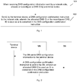
- An embodiment of the disclosure provides a method for allocating an ID of a data bearer, which is applied to a terminal device and may include the following operations shown in blocks 101 and 102 of Fig. 1 .
- the terminal device when receiving DRB configuration information sent by a network side, allocates or reconfigures a DRB ID.
- the terminal device sends a DRB configuration confirmation instruction to the network side, wherein the allocated DRB ID or the reconfigured DRB ID is used as or is contained in the DRB configuration confirmation instruction.
- the network side in this embodiment may be a network device at the network side, and for example, may be an SN or an MN.
- the operation that when receiving DRB configuration information sent by the network side, the terminal device allocates or reconfigures the DRB ID may be implemented as follows.
- one DRB ID is selected from at least one available DRB ID as the allocated DRB ID.
- an MN knows which DRB IDs have been used by a terminal device, including those of a MCG bearer and a split bearer. DRB IDs corresponding to the split bearer on the MN and the SN are the same.
- the SN can know DRB IDs of the split bearer and the SCG bearer.
- the terminal device knows DRB IDs corresponding to the MCG bearer, the split bearer and the SCG bearer.
- a terminal device may allocate the DRB ID from at least one available DRB ID, and provide the DRB ID to a base station via an uplink Radio Resource Control (RRC) message.
- RRC Radio Resource Control
- the processing scenario is described from a perspective of information interaction between the SN and the terminal device.
- the SN sends the DRB configuration information to the terminal device, where a DRB ID is not contained in the DRB configuration information.
- the terminal device selects one DRB ID from at least one available DRB ID as the allocated DRB ID, uses the allocated DRB ID as a DRB configuration confirmation instruction or arranges a DRB configuration confirmation instruction to contain the allocated DRB ID, and sends the DRB configuration confirmation instruction to the SN.
- a terminal device When the DRB configuration information contains a temporary DRB ID allocated by the network side, a terminal device reselects a DRB ID, and replaces the temporary DRB ID with the reselected DRB ID.
- the operation that the terminal device reselects the DRB ID may be implemented as follows.
- One DRB ID is selected from at least one available DRB ID.
- an MN knows which DRB IDs have been used by a terminal device, including those of a MCG bearer and a split bearer. DRB IDs corresponding to the split bearer on the MN and the SN are the same. The SN can know DRB IDs of the split bearer and the SCG bearer. The terminal device knows DRB IDs corresponding to the MCG bearer, the split bearer and the SCG bearer. Hence, when an MN configures to increase a DRB without providing any configuration for a DRB ID, a terminal device may allocate the DRB ID from at least one available DRB ID, and provide the DRB ID to a base station via an RRC message.
- the terminal device may rewrite, i.e., reconfigure the DRB ID configured by the network side.
- the terminal device may select one DRB ID from at least one available DRB ID known to the terminal device as the reconfigured DRB ID.
- the interaction between the SN and the terminal device is described and may include the following operations.
- the SN sends DRB configuration information to the terminal device, where the DRB configuration information contains a temporary DRB ID allocated by the network side.
- the terminal device selects one DRB ID from at least one available DRB ID as a reconfigured DRB ID, uses the reconfigured DRB ID as a DRB configuration confirmation instruction or arranges a DRB configuration confirmation instruction to contain the reconfigured DRB ID, and sends the DRB configuration confirmation instruction to the SN.
- a manner for acquiring DRB configuration information may be as follows: a downlink RRC reconfiguration message sent by the network side is received; and DRB configuration information carried in the downlink RRC reconfiguration message is acquired.
- a manner for sending the DRB configuration confirmation instruction may be as follows: an RRC message carrying the DRB configuration confirmation instruction is sent to the network side.
- An embodiment of the disclosure provides a method for configuring a DRB ID, which is different from an existing LTE DC.
- a DRB ID which is different from an existing LTE DC.
- an ID of a newly increased DRB is not allocated in a downlink RRC reconfiguration message, or only a temporary ID of the DRB is allocated.
- the terminal device receives the configuration signaling, the terminal device allocates a DRB ID, or the terminal device reconfigures the DRB ID temporarily allocated by the SN.
- the terminal device can allocate or reconfigure the DRB ID, so that the problem of a potential conflict of the DRB ID when the MN and the SN respectively and independently configure a DRB can be solved.
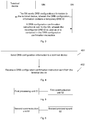
- An embodiment of the disclosure provides a method for allocating an ID of a data bearer, which is applied to a network device and may include the following operations as shown in blocks 401 and 402 of Fig. 4 .
- DRB configuration information is sent to a terminal device.
- a DRB configuration confirmation instruction sent from the terminal device is received, where the DRB configuration confirmation instruction contains a DRB ID allocated or reconfigured by the terminal device or a DRB ID allocated or reconfigured by the terminal device is used as the DRB configuration confirmation instruction.
- the network device in this embodiment may be an SN or an MN.
- the DRB configuration information not containing a DRB ID allocated by a network side is sent to a terminal device.
- the terminal device selects one DRB ID from at least one available DRB ID as the allocated DRB ID.
- an MN knows which DRB IDs have been used by the terminal device, including those of a MCG bearer and a split bearer. DRB IDs corresponding to the split bearer on the MN and the SN are the same.
- the SN can know DRB IDs of the split bearer and the SCG bearer.
- the terminal device knows DRB IDs corresponding to the MCG bearer, the split bearer and the SCG bearer.
- a terminal device may allocate the DRB ID from at least one available DRB ID, and provide the DRB ID to a base station via an RRC message.
- the processing scenario is described from a perspective of information interaction between the SN and the terminal device.
- the SN sends the DRB configuration information to the terminal device, where a DRB ID is not contained in the DRB configuration information.
- the terminal device selects one DRB ID from at least one available DRB ID as the allocated DRB ID, uses the allocated DRB ID as a DRB configuration confirmation instruction or arranges a DRB configuration confirmation instruction to contain the allocated DRB ID, and sends the DRB configuration confirmation instruction to the SN.
- the DRB configuration information containing a temporary DRB ID is sent to a terminal device.
- the terminal device reselects one DRB ID, and replaces the temporary DRB ID with the reselected DRB ID.
- an MN knows which DRB IDs have been used by a terminal device, including those of a MCG bearer and a split bearer. DRB IDs corresponding to the split bearer on the MN and the SN are the same. The SN can know DRB IDs of the split bearer and the SCG bearer. The terminal device knows DRB IDs corresponding to the MCG bearer, the split bearer and the SCG bearer. Hence, when an MN configures to increase a DRB without providing any configuration for a DRB ID, a terminal device may allocate the DRB ID from at least one available DRB ID, and provide the DRB ID to a base station via an RRC message.
- the terminal device may rewrite, i.e., reconfigure the DRB ID configured by the network side.
- the terminal device may select one DRB ID from at least one available DRB ID known to the terminal device as the reconfigured DRB ID.
- the interaction between the SN and the terminal device is described and may include the following operations.
- the SN sends DRB configuration information to the terminal device, where the DRB configuration information contains a temporary DRB ID allocated by the network side.
- the terminal device selects one DRB ID from at least one available DRB ID as a reconfigured DRB ID, uses the reconfigured DRB ID as a DRB configuration confirmation instruction or arranges a DRB configuration confirmation instruction to contain the reconfigured DRB ID, and sends the DRB configuration confirmation instruction to the SN.
- the operation that DRB configuration information is sent to a terminal device may be implemented as follows.
- DRB configuration information carried in a downlink RRC reconfiguration message is sent to the terminal device.
- the operation that the DRB configuration confirmation instruction sent from the terminal device is received may be implemented as follows.
- the DRB configuration confirmation instruction is acquired from an RRC message sent from the terminal device.
- An embodiment of the disclosure provides a method for configuring DRB IDs, which is different from the existing LTE DC.
- the SN configures a DRB
- an ID of a newly increased DRB is not allocated in a downlink RRC reconfiguration message, or only a temporary ID of the DRB is allocated.
- the terminal device receives the configuration signaling, the terminal device allocates a DRB ID, or the terminal device reconfigures the DRB ID temporarily allocated by the SN.
- the terminal device can allocate or reconfigure the DRB ID, so that the problem of a potential conflict of the DRB ID when the MN and the SN respectively and independently configure a DRB can be solved.
- An embodiment of the disclosure provides a terminal device, which may include a first processing unit 51 and a first communication unit 52, as shown in Fig. 5 .
- the first processing unit 51 is configured to allocate or reconfigure, when receiving DRB configuration information sent by a network side, a DRB ID, and use the allocated DRB ID or the reconfigured DRB ID as a DRB configuration confirmation instruction or arrange a DRB configuration confirmation instruction to contain the allocated DRB ID or the reconfigured DRB ID.
- the first communication unit 52 is configured to send the DRB configuration confirmation instruction to the network side.
- the network side in this embodiment may be a network device at the network side, and for example, may be an SN or an MN.
- the first processing unit 51 selects, when the DRB configuration information does not contain a DRB ID allocated by the network side, one DRB ID from at least one available DRB ID as the allocated DRB ID.
- an MN knows which DRB IDs have been used by the terminal device, including those of a MCG bearer and a split bearer. DRB IDs corresponding to the split bearer on the MN and the SN are the same.
- the SN can know DRB IDs of the split bearer and the SCG bearer.
- the terminal device knows DRB IDs corresponding to the MCG bearer, the split bearer and the SCG bearer.
- a terminal device may allocate the DRB ID from at least one available DRB ID, and provide the DRB ID to a base station via an RRC message.
- the processing scenario is described from a perspective of information interaction between the SN and the terminal device.
- the SN sends the DRB configuration information to the terminal device, where a DRB ID is not contained in the DRB configuration information.
- the terminal device selects one DRB ID from at least one available DRB ID as the allocated DRB ID, uses the allocated DRB ID as a DRB configuration confirmation instruction or arranges a DRB configuration confirmation instruction to contain the allocated DRB ID, and sends the DRB configuration confirmation instruction to the SN.
- the first processing unit 51 is configured to, when the DRB configuration information contains a temporary DRB ID allocated by the network side, reselect a DRB ID, and replace the temporary DRB ID with the reselected DRB ID.
- the first processing unit 51 selects one DRB ID from at least one available DRB ID.
- an MN knows which DRB IDs have been used by a terminal device, including those of a MCG bearer and a split bearer. DRB IDs corresponding to the split bearer on the MN and the SN are the same. The SN can know DRB IDs of the split bearer and the SCG bearer. The terminal device knows DRB IDs corresponding to the MCG bearer, the split bearer and the SCG bearer. Hence, when an MN configures to increase a DRB without providing any configuration for a DRB ID, a terminal device may allocate the DRB ID from at least one available DRB ID, and provide the DRB ID to a base station via an RRC message.
- the terminal device may rewrite, i.e., reconfigure the DRB ID configured by the network side.
- the terminal device may select one DRB ID from at least one available DRB ID known to the terminal device as the reconfigured DRB ID.
- the interaction between the SN and the terminal device is described and may include the following operations.
- the SN sends DRB configuration information to the terminal device, where the DRB configuration information contains a temporary DRB ID allocated by the network side.
- the terminal device selects one DRB ID from at least one available DRB ID as a reconfigured DRB ID, uses the reconfigured DRB ID as a DRB configuration confirmation instruction or arranges a DRB configuration confirmation instruction to contain the reconfigured DRB ID, and sends the DRB configuration confirmation instruction to the SN.
- a manner for acquiring the DRB configuration information may be as follows.
- the first communication unit 52 is configured to receive a downlink RRC reconfiguration message sent by the network side.
- the first processing unit 51 is configured to acquire DRB configuration information carried in the downlink RRC reconfiguration message.
- a manner for sending the DRB configuration confirmation instruction may be as follows.
- the first communication unit 52 is configured to send an RRC message carrying the DRB configuration confirmation instruction to the network side.
- the terminal device can allocate or reconfigure the DRB ID, so that the problem of a potential conflict of the DRB ID when the MN and the SN respectively and independently configure a DRB can be solved.
- An embodiment of the disclosure provides a network device, which may include a second communication unit 61 as shown in Fig. 6 .
- the second communication unit 61 is configured to send DRB configuration confirmation to a terminal device; and receive a DRB configuration confirmation instruction sent from the terminal device, where the DRB configuration confirmation instruction contains a DRB ID allocated or reconfigured by the terminal device or a DRB ID allocated or reconfigured by the terminal device is used as the DRB configuration confirmation instruction.
- the network device in this embodiment may be an SN or an MN.
- the network device may further include a second processing unit 62.
- the second processing unit 62 is configured to provide no DRB ID in the DRB configuration information.
- the second communication unit 61 is configured to send the DRB configuration information not containing a DRB ID allocated by the network side to a terminal device.
- the terminal device selects one DRB ID from at least one available DRB ID as the allocated DRB ID.
- an MN knows which DRB IDs have been used by the terminal device, including those of a MCG bearer and a split bearer. DRB IDs corresponding to the split bearer on the MN and the SN are the same.
- the SN can know DRB IDs of the split bearer and the SCG bearer.
- the terminal device knows DRB IDs corresponding to the MCG bearer, the split bearer and the SCG bearer.
- a terminal device may allocate the DRB ID from at least one available DRB ID, and provide the DRB ID to a base station via an RRC message.
- the second processing unit 62 is configured to provide a temporary DRB ID in the DRB configuration information.
- the second communication unit 61 is configured to send the DRB configuration information containing the temporary DRB ID to a terminal device.
- the terminal device reselects one DRB ID, and replaces the temporary DRB ID with the reselected DRB ID.
- an MN knows which DRB IDs have been used by a terminal device, including those of a MCG bearer and a split bearer. DRB IDs corresponding to the split bearer on the MN and the SN are the same. The SN can know DRB IDs of the split bearer and the SCG bearer. The terminal device knows DRB IDs corresponding to the MCG bearer, the split bearer and the SCG bearer. Hence, when an MN configures to increase a DRB without providing any configuration for a DRB ID, a terminal device may allocate the DRB ID from at least one available DRB ID, and provide the DRB ID to a base station via an RRC message.
- the terminal device may rewrite, i.e., reconfigure the DRB ID configured by the network side.
- the terminal device may select one DRB ID from at least one available DRB ID known to the terminal device as the reconfigured DRB ID.
- the second communication unit 61 is configured to send DRB configuration information carried in a downlink RRC reconfiguration message to the terminal device.
- the second communication unit 61 is configured to receive an RRC message sent from the terminal device.
- the second processing unit 62 is configured to acquire the DRB configuration confirmation instruction from the RRC message.
- the embodiment of the disclosure provides a scheme for configuring a DRB ID, which is different from the existing LTE DC.
- the SN configures a DRB
- an ID of a newly increased DRB is not allocated in a downlink RRC reconfiguration message, or only a temporary ID of the DRB is allocated.
- the terminal device receives the configuration signaling, the terminal device allocates a DRB ID, or the terminal device reconfigures the DRB ID temporarily allocated by the SN.
- the terminal device can allocate or reconfigure the DRB ID, so that the problem of a potential conflict of the DRB ID when the MN and the SN respectively and independently configure a DRB can be solved.
- An embodiment of the disclosure further provides hardware architecture of a receiving party device.
- the hardware architecture may include: at least one processor 71, a memory 72 and at least one network interface 73.
- Various components are coupled together via a bus system 74.
- the bus system 74 is configured to implement communication and connection among these components.
- the bus system 74 may further include a power bus, a control bus and a state signal bus.
- various buses are integrally marked as the bus system 74 in Fig. 7 .
- the memory 72 in this embodiment of the disclosure may be a volatile memory or a nonvolatile memory, or may include both of the volatile memory and the nonvolatile memory.
- the memory 72 stores the following elements: an executable module or data structure, or a subset thereof, or an extension set thereof: an operation system 721 and an application program 722.
- the processor 71 is configured to process the operations of the method in the foregoing first embodiment, which will not be repeated here.
- An embodiment of the disclosure provides a computer storage medium; the computer storage medium stores a computer executable instruction; and the computer storage medium, when being executed, implements operations of the method of the foregoing first embodiment.
- the apparatus in the embodiments of the disclosure may also be stored in a computer-readable storage medium.
- the technical solutions of the embodiments of the disclosure substantially or parts making contributions to the conventional art may be embodied in form of software product, and the computer software product is stored in a storage medium, including a plurality of instructions configured to enable a piece of computer equipment (which may be a personal computer, a server, network equipment or the like) to execute all or part of the method in each embodiment of the disclosure.
- the above-mentioned storage medium includes: various media capable of storing program codes such as a U disk, a mobile hard disk, a Read Only Memory (ROM), a magnetic disk or an optical disk. In this way, the embodiments of the disclosure are not limited to any special hardware and software combination.
- an embodiment of the disclosure provides a computer storage medium, which stores a computer program; and the computer program is configured to execute a data scheduling method in an embodiment of the disclosure.
Landscapes
- Engineering & Computer Science (AREA)
- Signal Processing (AREA)
- Computer Networks & Wireless Communication (AREA)
- Mobile Radio Communication Systems (AREA)
Claims (11)
- Verfahren zum Zuteilen einer Kennung, ID, eines Datenträgers, das auf eine Endgerätevorrichtung angewendet wird und Folgendes umfasst:wenn Datenfunkträger(DRB)-Auslegungsinformationen, die von einer Netzwerkseite gesendet werden, empfangen werden, Zuteilen oder Neuauslegen (101) einer DRB-ID durch die Endgerätevorrichtung, wobei die Netzwerkseite auf ein duales Verbindungssystem angewendet wird, das Folgendes umfasst: einen Masterknoten, MN, und einen sekundären Knoten, SN, und wobei der SN zum Auslegen einer DRB-ID verwendet wird; undSenden (102) einer DRB-Auslegungsbestätigungsanweisung durch die Endgerätevorrichtung an die Netzwerkseite, wobei die DRB-Auslegungsbestätigungsanweisung Folgendes umfasst: eine zugeteilte DRB-ID oder eine neu ausgelegte DRB-ID;wobei das Zuteilen oder Neuauslegen (101) der DRB-ID durch die Endgerätevorrichtung, wenn die DRB-Auslegungsinformationen, die von der Netzwerkseite gesendet werden, empfangen werden, Folgendes umfasst:Auswählen von einer DRB-ID aus mindestens einer verfügbaren DRB-ID als die zugeteilte DRB-ID, wenn die DRB-Auslegungsinformationen keine DRB-ID enthalten, die durch die Netzwerkseite zugeteilt ist; oderNeuauswählen einer DRB-ID durch die Endgerätevorrichtung und Ersetzen einer temporären DRB-ID durch die neu ausgewählte DRB-ID durch die Endgerätevorrichtung, wenn die DRB-Auslegungsinformationen die temporäre DRB-ID enthalten, die durch die Netzwerkseite zugeteilt ist.
- Verfahren nach Anspruch 1, wobei das Neuauswählen der DRB-ID durch die Endgerätevorrichtung Folgendes umfasst:
Auswählen von einer DRB-ID aus mindestens einer verfügbaren DRB-ID. - Verfahren nach einem der Ansprüche 1 bis 2, das ferner Folgendes umfasst:
Empfangen einer Downlinkfunkressourcensteuerungs(RRC)-Neuauslegungsnachricht, die von der Netzwerkseite gesendet wird, und Erfassen von DRB-Auslegungsinformationen, die in der Downlink-RRC-Neuauslegungsnachricht enthalten sind. - Verfahren nach einem der Ansprüche 1 bis 2, wobei das Senden (102) der DRB-Auslegungsbestätigungsanweisung an die Netzwerkseite Folgendes umfasst:
Senden einer Funkressourcensteuerungs(RRC)-Nachricht, die die DRB-Auslegungsbestätigungsanweisung enthält, an die Netzwerkseite. - Endgerätevorrichtung, die Folgendes umfasst:eine erste Verarbeitungseinheit (51), die, wenn Datenfunkträger(DRB)-Auslegungsinformationen, die von einer Netzwerkseite gesendet werden, empfangen werden, dazu ausgelegt ist, eine DRB-Kennung, ID, zuzuteilen oder neu auszulegen und anzuordnen, dass eine DRB-Auslegungsbestätigungsanweisung die zugeteilte DRB-ID oder die neu ausgelegte DRB-ID enthält, wobei die Netzwerkseite auf ein duales Verbindungssystem angewendet wird, das Folgendes umfasst: einen Masterknoten, MN, und einen sekundären Knoten, SN, und wobei der SN zum Auslegen einer DRB-ID verwendet wird; undeine erste Kommunikationseinheit (52), die dazu ausgelegt ist, die DRB-Auslegungsbestätigungsanweisung an die Netzwerkseite zu senden;wobei, wenn die DRB-Auslegungsinformationen keine DRB-ID enthält, die durch die Netzwerkseite zugeteilt ist, die erste Verarbeitungseinheit (51) dazu ausgelegt ist, eine DRB-ID aus mindestens einer verfügbaren DRB-ID als die zugeteilte DRB-ID auszuwählen; oder, wenn die DRB-Auslegungsinformationen eine temporäre DRB-ID enthalten, die durch die Netzwerkseite zugeteilt ist, die erste Verarbeitungseinheit (51) dazu ausgelegt ist, eine DRB-ID neu auszuwählen und die temporäre DRB-ID durch die neu ausgewählte DRB-ID zu ersetzen.
- Endgerätevorrichtung nach Anspruch 5, wobei die erste Verarbeitungseinheit (51) dazu ausgelegt ist, eine DRB-ID aus mindestens einer verfügbaren DRB-ID auszuwählen.
- Endgerätevorrichtung nach einem der Ansprüche 5 bis 6, wobeidie erste Kommunikationseinheit (52) dazu ausgelegt ist, eine Downlinkfunkressourcensteuerungs(RRC)-Neuauslegungsnachricht, die von der Netzwerkseite gesendet wird, zu empfangen; unddie erste Verarbeitungseinheit (51) dazu ausgelegt ist, DRB-Auslegungsinformationen, die in der Downlink-RRC-Neuauslegungsnachricht enthalten sind, zu erfassen.
- Endgerätevorrichtung nach einem der Ansprüche 5 bis 6, wobei
die erste Kommunikationseinheit (52) dazu ausgelegt ist, eine Funkressourcensteuerungs(RRC)-Nachricht, die die DRB-Auslegungsbestätigungsanweisung enthält, an die Netzwerkseite zu senden. - Netzwerkvorrichtung, die auf ein duales Verbindungssystem angewendet wird, das einen Masterknoten, MN, und einen sekundären Knoten, SN, umfasst, wobei der SN zum Auslegen einer DRB-ID verwendet wird und die Netzwerkvorrichtung Folgendes umfasst:eine zweite Kommunikationseinheit (61), die dazu ausgelegt ist, Datenfunkträger(DRB)-Auslegungsinformationen an eine Endgerätevorrichtung zu senden und eine DRB-Auslegungsbestätigungsanweisung, die von der Endgerätevorrichtung gesendet wird, zu empfangen, wobei die DRB-Auslegungsbestätigungsanweisung eine DRB-Kennung, ID, enthält, die von der Endgerätevorrichtung zugeteilt oder neu ausgelegt wird;wobei die DRB-Auslegungsinformationen keine DRB-ID enthalten, die von der Netzwerkvorrichtung zugeteilt ist, oder die DRB-Auslegungsinformationen eine temporäre DRB-ID enthalten, die von der Netzwerkvorrichtung zugeteilt ist.
- Endgerätevorrichtung, die einen Prozessor (71) und einen Speicher (72), der dazu ausgelegt ist, ein Computerprogramm zu speichern, das vom Prozessor (71) ausgeführt werden kann, umfasst,
wobei der Prozessor (71), wenn er das Computerprogramm ausführt, die Operationen des Verfahrens nach einem der Ansprüche 1 bis 4 implementiert. - Computerspeichermedium, wobei auf dem Computerspeichermedium eine von einem Computer ausführbare Anweisung gespeichert ist und das Computerspeichermedium, wenn es ausgeführt wird, Operationen des Verfahrens nach einem der Ansprüche 1 bis 4 implementiert.
Applications Claiming Priority (1)
| Application Number | Priority Date | Filing Date | Title |
|---|---|---|---|
| PCT/CN2018/071526 WO2019134114A1 (zh) | 2018-01-05 | 2018-01-05 | 一种数据承载的标识分配方法、终端设备及网络设备 |
Publications (3)
| Publication Number | Publication Date |
|---|---|
| EP3534667A1 EP3534667A1 (de) | 2019-09-04 |
| EP3534667A4 EP3534667A4 (de) | 2019-11-06 |
| EP3534667B1 true EP3534667B1 (de) | 2021-09-01 |
Family
ID=66191866
Family Applications (1)
| Application Number | Title | Priority Date | Filing Date |
|---|---|---|---|
| EP18852760.0A Active EP3534667B1 (de) | 2018-01-05 | 2018-01-05 | Verfahren zur zuordnung eines identifikators eines datenträgers sowie endgerätevorrichtung und netzwerkvorrichtung |
Country Status (4)
| Country | Link |
|---|---|
| US (1) | US11431457B2 (de) |
| EP (1) | EP3534667B1 (de) |
| CN (1) | CN109691007B (de) |
| WO (1) | WO2019134114A1 (de) |
Families Citing this family (1)
| Publication number | Priority date | Publication date | Assignee | Title |
|---|---|---|---|---|
| CN111132228B (zh) * | 2019-12-25 | 2022-07-15 | 展讯半导体(成都)有限公司 | Rrc重配置消息的处理方法及装置、存储介质、终端 |
Family Cites Families (25)
| Publication number | Priority date | Publication date | Assignee | Title |
|---|---|---|---|---|
| CN103517351B (zh) | 2012-06-29 | 2016-09-14 | 华为技术有限公司 | Drb建立方法及设备 |
| JP5937760B2 (ja) | 2012-07-31 | 2016-06-22 | ▲ホア▼▲ウェイ▼技術有限公司Huawei Technologies Co.,Ltd. | リンク障害復旧方法および装置 |
| US9526044B2 (en) | 2013-05-08 | 2016-12-20 | Lg Electronics Inc. | Method of configuring dual connectivity to UE in heterogeneous cell deployment |
| CN104244426B (zh) | 2013-06-09 | 2019-02-05 | 华为技术有限公司 | 一种数据无线承载drb的资源分配方法及装置 |
| CN104754750B (zh) | 2013-12-31 | 2018-10-19 | 华为终端(东莞)有限公司 | 资源分配方法和装置 |
| CN104797000B (zh) | 2014-01-21 | 2018-06-19 | 普天信息技术有限公司 | 双连接网络中的无线承载建立方法及系统 |
| CN105228263B (zh) | 2014-06-30 | 2020-05-05 | 中兴通讯股份有限公司 | Drb转换方法及装置 |
| EP3661251B1 (de) | 2014-08-08 | 2021-12-01 | Huawei Technologies Co., Ltd. | Funkträgerverarbeitungsverfahren, benutzergerät und basisstation |
| US9788242B2 (en) * | 2015-02-05 | 2017-10-10 | Mediatek Inc. | Network selection and data aggregation with LTE-WLAN aggregation |
| RU2633612C2 (ru) * | 2015-02-13 | 2017-10-16 | Телефонактиеболагет Л М Эрикссон (Пабл) | Установление возможности двойного соединения |
| CN112437491A (zh) | 2015-05-15 | 2021-03-02 | 夏普株式会社 | 用户设备和由用户设备执行的方法 |
| CN107113895B (zh) * | 2015-08-04 | 2020-10-09 | 华为技术有限公司 | 通信方法、网络侧设备和用户设备 |
| KR102002203B1 (ko) * | 2015-09-24 | 2019-10-02 | 주식회사 케이티 | Wlan 무선자원을 이용한 데이터 송수신 방법 및 그 장치 |
| CN107404750A (zh) * | 2016-05-18 | 2017-11-28 | 中兴通讯股份有限公司 | 一种接入方法及装置 |
| US10791562B2 (en) * | 2017-01-05 | 2020-09-29 | Samsung Electronics Co., Ltd. | Method and apparatus for transmitting and receiving data in wireless communication system |
| CN107018542A (zh) | 2017-03-27 | 2017-08-04 | 中兴通讯股份有限公司 | 网络系统中状态信息的处理方法、装置及存储介质 |
| KR102293998B1 (ko) * | 2017-03-30 | 2021-08-27 | 삼성전자 주식회사 | Tcp/ip를 고려한 데이터 처리 방법 |
| US10462695B2 (en) * | 2017-05-31 | 2019-10-29 | Htc Corporation | Device and method for handling measurement configuration in dual connectivity |
| WO2018230974A1 (en) * | 2017-06-14 | 2018-12-20 | Samsung Electronics Co., Ltd. | Method and user equipment for handling of integrity check failures of pdcp pdus |
| CN109246705B (zh) * | 2017-06-15 | 2020-10-23 | 维沃移动通信有限公司 | 一种数据无线承载完整性保护配置方法、终端及网络设备 |
| CN109246766B (zh) * | 2017-06-15 | 2023-05-30 | 夏普株式会社 | 无线配置方法和相应的用户设备 |
| CN109151915B (zh) * | 2017-06-16 | 2023-11-17 | 夏普株式会社 | 用于数据分组递送的方法、用户设备和基站 |
| CN109246844B (zh) * | 2017-06-16 | 2022-07-15 | 中兴通讯股份有限公司 | 无线承载的配置方法及系统 |
| CN111386725B (zh) * | 2017-09-28 | 2023-03-21 | 三星电子株式会社 | 用于在无线通信系统中处理pdcp操作的方法和系统 |
| JP7142426B2 (ja) * | 2017-11-15 | 2022-09-27 | シャープ株式会社 | 端末装置および方法 |
-
2018
- 2018-01-05 EP EP18852760.0A patent/EP3534667B1/de active Active
- 2018-01-05 WO PCT/CN2018/071526 patent/WO2019134114A1/zh unknown
- 2018-01-05 US US16/340,992 patent/US11431457B2/en active Active
- 2018-01-05 CN CN201880003417.XA patent/CN109691007B/zh active Active
Also Published As
| Publication number | Publication date |
|---|---|
| US11431457B2 (en) | 2022-08-30 |
| US20210367733A1 (en) | 2021-11-25 |
| WO2019134114A1 (zh) | 2019-07-11 |
| CN109691007A (zh) | 2019-04-26 |
| EP3534667A4 (de) | 2019-11-06 |
| EP3534667A1 (de) | 2019-09-04 |
| CN109691007B (zh) | 2020-09-15 |
Similar Documents
| Publication | Publication Date | Title |
|---|---|---|
| EP3327992B1 (de) | Verfahren zur auswahl eines netzwerksegments und dieses verwendendes system | |
| CN110830543B (zh) | 通信方法和通信设备 | |
| CN110896355A (zh) | 一种网络切片的选择方法及装置 | |
| WO2015188766A1 (en) | Methods and systems for managing capacity in a virtualized network | |
| CN109803312B (zh) | 切换方法、终端和网络侧设备 | |
| CN110213066B (zh) | 一种切片信息的获取方法和中继装置 | |
| EP3334212B1 (de) | Duale-konnektivitäts netzwerkkonfigurationsverfahren und vorrichtung | |
| US20180152949A1 (en) | Interference cancellation method, user equipment, and base station | |
| CN107371205B (zh) | 基站间切换方法及装置 | |
| CN109392056B (zh) | 一种终端接入核心网的方法、基站及终端 | |
| CN111132351B (zh) | 一种资源分配方法、终端及节点设备 | |
| JP2020513174A5 (de) | ||
| EP3534667B1 (de) | Verfahren zur zuordnung eines identifikators eines datenträgers sowie endgerätevorrichtung und netzwerkvorrichtung | |
| US20210368424A1 (en) | Information indication method, apparatus, system and device, and storage medium | |
| CN101848056B (zh) | 数据包的传输方法和装置 | |
| EP3737158B1 (de) | Verfahren zur zuordnung eines identifikators eines datenträgers bei dualer konnektivität und netzwerknoten | |
| US9807745B2 (en) | Resource allocation method and apparatus for relay node under the condition of carrier aggregation | |
| US20150109945A1 (en) | On-demand transmission path providing system and method | |
| CN111757318A (zh) | 一种通信方法和装置 | |
| US20230189311A1 (en) | Data transmission method, network device and system in multi-connectivity network | |
| CN115866556A (zh) | 资源共存方法及装置 | |
| KR20230017311A (ko) | 사용자 평면 보안 시행 정보 결정 방법, 장치 및 시스템 | |
| CN111726427B (zh) | 一种信息处理方法、设备及计算机可读存储介质 | |
| CN112312420A (zh) | 最小化路测的处理、配置方法、装置、终端及网络侧设备 | |
| CN112996074B (zh) | 共享小区下的路由方法、装置、终端设备及存储介质 |
Legal Events
| Date | Code | Title | Description |
|---|---|---|---|
| STAA | Information on the status of an ep patent application or granted ep patent |
Free format text: STATUS: UNKNOWN |
|
| STAA | Information on the status of an ep patent application or granted ep patent |
Free format text: STATUS: THE INTERNATIONAL PUBLICATION HAS BEEN MADE |
|
| PUAI | Public reference made under article 153(3) epc to a published international application that has entered the european phase |
Free format text: ORIGINAL CODE: 0009012 |
|
| STAA | Information on the status of an ep patent application or granted ep patent |
Free format text: STATUS: REQUEST FOR EXAMINATION WAS MADE |
|
| 17P | Request for examination filed |
Effective date: 20190314 |
|
| AK | Designated contracting states |
Kind code of ref document: A1 Designated state(s): AL AT BE BG CH CY CZ DE DK EE ES FI FR GB GR HR HU IE IS IT LI LT LU LV MC MK MT NL NO PL PT RO RS SE SI SK SM TR |
|
| AX | Request for extension of the european patent |
Extension state: BA ME |
|
| A4 | Supplementary search report drawn up and despatched |
Effective date: 20191004 |
|
| RIC1 | Information provided on ipc code assigned before grant |
Ipc: H04W 48/08 20090101ALI20190927BHEP Ipc: H04W 76/11 20180101ALI20190927BHEP Ipc: H04W 76/00 20180101AFI20190927BHEP |
|
| RAP1 | Party data changed (applicant data changed or rights of an application transferred) |
Owner name: GUANGDONG OPPO MOBILE TELECOMMUNICATIONS CORP., LT |
|
| STAA | Information on the status of an ep patent application or granted ep patent |
Free format text: STATUS: EXAMINATION IS IN PROGRESS |
|
| 17Q | First examination report despatched |
Effective date: 20200414 |
|
| STAA | Information on the status of an ep patent application or granted ep patent |
Free format text: STATUS: EXAMINATION IS IN PROGRESS |
|
| REG | Reference to a national code |
Ref country code: DE Ref legal event code: R079 Ref document number: 602018023069 Country of ref document: DE Free format text: PREVIOUS MAIN CLASS: H04W0076000000 Ipc: H04W0076110000 |
|
| GRAP | Despatch of communication of intention to grant a patent |
Free format text: ORIGINAL CODE: EPIDOSNIGR1 |
|
| STAA | Information on the status of an ep patent application or granted ep patent |
Free format text: STATUS: GRANT OF PATENT IS INTENDED |
|
| DAV | Request for validation of the european patent (deleted) | ||
| DAX | Request for extension of the european patent (deleted) | ||
| INTG | Intention to grant announced |
Effective date: 20210406 |
|
| RIC1 | Information provided on ipc code assigned before grant |
Ipc: H04L 5/00 20060101ALI20210322BHEP Ipc: H04W 76/15 20180101ALI20210322BHEP Ipc: H04W 76/11 20180101AFI20210322BHEP |
|
| GRAS | Grant fee paid |
Free format text: ORIGINAL CODE: EPIDOSNIGR3 |
|
| GRAA | (expected) grant |
Free format text: ORIGINAL CODE: 0009210 |
|
| STAA | Information on the status of an ep patent application or granted ep patent |
Free format text: STATUS: THE PATENT HAS BEEN GRANTED |
|
| AK | Designated contracting states |
Kind code of ref document: B1 Designated state(s): AL AT BE BG CH CY CZ DE DK EE ES FI FR GB GR HR HU IE IS IT LI LT LU LV MC MK MT NL NO PL PT RO RS SE SI SK SM TR |
|
| REG | Reference to a national code |
Ref country code: GB Ref legal event code: FG4D |
|
| REG | Reference to a national code |
Ref country code: CH Ref legal event code: EP Ref country code: AT Ref legal event code: REF Ref document number: 1427639 Country of ref document: AT Kind code of ref document: T Effective date: 20210915 |
|
| REG | Reference to a national code |
Ref country code: DE Ref legal event code: R096 Ref document number: 602018023069 Country of ref document: DE |
|
| REG | Reference to a national code |
Ref country code: IE Ref legal event code: FG4D |
|
| REG | Reference to a national code |
Ref country code: LT Ref legal event code: MG9D |
|
| REG | Reference to a national code |
Ref country code: NL Ref legal event code: MP Effective date: 20210901 |
|
| PG25 | Lapsed in a contracting state [announced via postgrant information from national office to epo] |
Ref country code: FI Free format text: LAPSE BECAUSE OF FAILURE TO SUBMIT A TRANSLATION OF THE DESCRIPTION OR TO PAY THE FEE WITHIN THE PRESCRIBED TIME-LIMIT Effective date: 20210901 Ref country code: ES Free format text: LAPSE BECAUSE OF FAILURE TO SUBMIT A TRANSLATION OF THE DESCRIPTION OR TO PAY THE FEE WITHIN THE PRESCRIBED TIME-LIMIT Effective date: 20210901 Ref country code: SE Free format text: LAPSE BECAUSE OF FAILURE TO SUBMIT A TRANSLATION OF THE DESCRIPTION OR TO PAY THE FEE WITHIN THE PRESCRIBED TIME-LIMIT Effective date: 20210901 Ref country code: RS Free format text: LAPSE BECAUSE OF FAILURE TO SUBMIT A TRANSLATION OF THE DESCRIPTION OR TO PAY THE FEE WITHIN THE PRESCRIBED TIME-LIMIT Effective date: 20210901 Ref country code: HR Free format text: LAPSE BECAUSE OF FAILURE TO SUBMIT A TRANSLATION OF THE DESCRIPTION OR TO PAY THE FEE WITHIN THE PRESCRIBED TIME-LIMIT Effective date: 20210901 Ref country code: NO Free format text: LAPSE BECAUSE OF FAILURE TO SUBMIT A TRANSLATION OF THE DESCRIPTION OR TO PAY THE FEE WITHIN THE PRESCRIBED TIME-LIMIT Effective date: 20211201 Ref country code: LT Free format text: LAPSE BECAUSE OF FAILURE TO SUBMIT A TRANSLATION OF THE DESCRIPTION OR TO PAY THE FEE WITHIN THE PRESCRIBED TIME-LIMIT Effective date: 20210901 Ref country code: BG Free format text: LAPSE BECAUSE OF FAILURE TO SUBMIT A TRANSLATION OF THE DESCRIPTION OR TO PAY THE FEE WITHIN THE PRESCRIBED TIME-LIMIT Effective date: 20211201 |
|
| REG | Reference to a national code |
Ref country code: AT Ref legal event code: MK05 Ref document number: 1427639 Country of ref document: AT Kind code of ref document: T Effective date: 20210901 |
|
| PG25 | Lapsed in a contracting state [announced via postgrant information from national office to epo] |
Ref country code: PL Free format text: LAPSE BECAUSE OF FAILURE TO SUBMIT A TRANSLATION OF THE DESCRIPTION OR TO PAY THE FEE WITHIN THE PRESCRIBED TIME-LIMIT Effective date: 20210901 Ref country code: LV Free format text: LAPSE BECAUSE OF FAILURE TO SUBMIT A TRANSLATION OF THE DESCRIPTION OR TO PAY THE FEE WITHIN THE PRESCRIBED TIME-LIMIT Effective date: 20210901 Ref country code: GR Free format text: LAPSE BECAUSE OF FAILURE TO SUBMIT A TRANSLATION OF THE DESCRIPTION OR TO PAY THE FEE WITHIN THE PRESCRIBED TIME-LIMIT Effective date: 20211202 |
|
| PG25 | Lapsed in a contracting state [announced via postgrant information from national office to epo] |
Ref country code: AT Free format text: LAPSE BECAUSE OF FAILURE TO SUBMIT A TRANSLATION OF THE DESCRIPTION OR TO PAY THE FEE WITHIN THE PRESCRIBED TIME-LIMIT Effective date: 20210901 |
|
| PGFP | Annual fee paid to national office [announced via postgrant information from national office to epo] |
Ref country code: GB Payment date: 20220125 Year of fee payment: 5 |
|
| PG25 | Lapsed in a contracting state [announced via postgrant information from national office to epo] |
Ref country code: IS Free format text: LAPSE BECAUSE OF FAILURE TO SUBMIT A TRANSLATION OF THE DESCRIPTION OR TO PAY THE FEE WITHIN THE PRESCRIBED TIME-LIMIT Effective date: 20220101 Ref country code: SM Free format text: LAPSE BECAUSE OF FAILURE TO SUBMIT A TRANSLATION OF THE DESCRIPTION OR TO PAY THE FEE WITHIN THE PRESCRIBED TIME-LIMIT Effective date: 20210901 Ref country code: SK Free format text: LAPSE BECAUSE OF FAILURE TO SUBMIT A TRANSLATION OF THE DESCRIPTION OR TO PAY THE FEE WITHIN THE PRESCRIBED TIME-LIMIT Effective date: 20210901 Ref country code: RO Free format text: LAPSE BECAUSE OF FAILURE TO SUBMIT A TRANSLATION OF THE DESCRIPTION OR TO PAY THE FEE WITHIN THE PRESCRIBED TIME-LIMIT Effective date: 20210901 Ref country code: PT Free format text: LAPSE BECAUSE OF FAILURE TO SUBMIT A TRANSLATION OF THE DESCRIPTION OR TO PAY THE FEE WITHIN THE PRESCRIBED TIME-LIMIT Effective date: 20220103 Ref country code: NL Free format text: LAPSE BECAUSE OF FAILURE TO SUBMIT A TRANSLATION OF THE DESCRIPTION OR TO PAY THE FEE WITHIN THE PRESCRIBED TIME-LIMIT Effective date: 20210901 Ref country code: EE Free format text: LAPSE BECAUSE OF FAILURE TO SUBMIT A TRANSLATION OF THE DESCRIPTION OR TO PAY THE FEE WITHIN THE PRESCRIBED TIME-LIMIT Effective date: 20210901 Ref country code: CZ Free format text: LAPSE BECAUSE OF FAILURE TO SUBMIT A TRANSLATION OF THE DESCRIPTION OR TO PAY THE FEE WITHIN THE PRESCRIBED TIME-LIMIT Effective date: 20210901 Ref country code: AL Free format text: LAPSE BECAUSE OF FAILURE TO SUBMIT A TRANSLATION OF THE DESCRIPTION OR TO PAY THE FEE WITHIN THE PRESCRIBED TIME-LIMIT Effective date: 20210901 |
|
| REG | Reference to a national code |
Ref country code: DE Ref legal event code: R097 Ref document number: 602018023069 Country of ref document: DE |
|
| PLBE | No opposition filed within time limit |
Free format text: ORIGINAL CODE: 0009261 |
|
| STAA | Information on the status of an ep patent application or granted ep patent |
Free format text: STATUS: NO OPPOSITION FILED WITHIN TIME LIMIT |
|
| PG25 | Lapsed in a contracting state [announced via postgrant information from national office to epo] |
Ref country code: IT Free format text: LAPSE BECAUSE OF FAILURE TO SUBMIT A TRANSLATION OF THE DESCRIPTION OR TO PAY THE FEE WITHIN THE PRESCRIBED TIME-LIMIT Effective date: 20210901 Ref country code: DK Free format text: LAPSE BECAUSE OF FAILURE TO SUBMIT A TRANSLATION OF THE DESCRIPTION OR TO PAY THE FEE WITHIN THE PRESCRIBED TIME-LIMIT Effective date: 20210901 |
|
| REG | Reference to a national code |
Ref country code: DE Ref legal event code: R119 Ref document number: 602018023069 Country of ref document: DE |
|
| 26N | No opposition filed |
Effective date: 20220602 |
|
| PG25 | Lapsed in a contracting state [announced via postgrant information from national office to epo] |
Ref country code: SI Free format text: LAPSE BECAUSE OF FAILURE TO SUBMIT A TRANSLATION OF THE DESCRIPTION OR TO PAY THE FEE WITHIN THE PRESCRIBED TIME-LIMIT Effective date: 20210901 Ref country code: MC Free format text: LAPSE BECAUSE OF FAILURE TO SUBMIT A TRANSLATION OF THE DESCRIPTION OR TO PAY THE FEE WITHIN THE PRESCRIBED TIME-LIMIT Effective date: 20210901 |
|
| REG | Reference to a national code |
Ref country code: CH Ref legal event code: PL |
|
| REG | Reference to a national code |
Ref country code: BE Ref legal event code: MM Effective date: 20220131 |
|
| PG25 | Lapsed in a contracting state [announced via postgrant information from national office to epo] |
Ref country code: LU Free format text: LAPSE BECAUSE OF NON-PAYMENT OF DUE FEES Effective date: 20220105 Ref country code: DE Free format text: LAPSE BECAUSE OF NON-PAYMENT OF DUE FEES Effective date: 20220802 |
|
| PG25 | Lapsed in a contracting state [announced via postgrant information from national office to epo] |
Ref country code: FR Free format text: LAPSE BECAUSE OF NON-PAYMENT OF DUE FEES Effective date: 20220131 Ref country code: BE Free format text: LAPSE BECAUSE OF NON-PAYMENT OF DUE FEES Effective date: 20220131 |
|
| PG25 | Lapsed in a contracting state [announced via postgrant information from national office to epo] |
Ref country code: LI Free format text: LAPSE BECAUSE OF NON-PAYMENT OF DUE FEES Effective date: 20220131 Ref country code: CH Free format text: LAPSE BECAUSE OF NON-PAYMENT OF DUE FEES Effective date: 20220131 |
|
| PG25 | Lapsed in a contracting state [announced via postgrant information from national office to epo] |
Ref country code: IE Free format text: LAPSE BECAUSE OF NON-PAYMENT OF DUE FEES Effective date: 20220105 |
|
| P01 | Opt-out of the competence of the unified patent court (upc) registered |
Effective date: 20230412 |
|
| GBPC | Gb: european patent ceased through non-payment of renewal fee |
Effective date: 20230105 |
|
| PG25 | Lapsed in a contracting state [announced via postgrant information from national office to epo] |
Ref country code: GB Free format text: LAPSE BECAUSE OF NON-PAYMENT OF DUE FEES Effective date: 20230105 |
|
| PG25 | Lapsed in a contracting state [announced via postgrant information from national office to epo] |
Ref country code: MK Free format text: LAPSE BECAUSE OF FAILURE TO SUBMIT A TRANSLATION OF THE DESCRIPTION OR TO PAY THE FEE WITHIN THE PRESCRIBED TIME-LIMIT Effective date: 20210901 Ref country code: CY Free format text: LAPSE BECAUSE OF FAILURE TO SUBMIT A TRANSLATION OF THE DESCRIPTION OR TO PAY THE FEE WITHIN THE PRESCRIBED TIME-LIMIT Effective date: 20210901 |