EP3534633B1 - Système de communication , station de base et procédé de commande - Google Patents
Système de communication , station de base et procédé de commande Download PDFInfo
- Publication number
- EP3534633B1 EP3534633B1 EP17863947.2A EP17863947A EP3534633B1 EP 3534633 B1 EP3534633 B1 EP 3534633B1 EP 17863947 A EP17863947 A EP 17863947A EP 3534633 B1 EP3534633 B1 EP 3534633B1
- Authority
- EP
- European Patent Office
- Prior art keywords
- enb
- gnb
- capability
- security
- security key
- Prior art date
- Legal status (The legal status is an assumption and is not a legal conclusion. Google has not performed a legal analysis and makes no representation as to the accuracy of the status listed.)
- Active
Links
- 238000000034 method Methods 0.000 title claims description 52
- 238000004891 communication Methods 0.000 title description 98
- 230000009977 dual effect Effects 0.000 claims description 46
- 238000005516 engineering process Methods 0.000 description 28
- 230000004044 response Effects 0.000 description 25
- 238000009795 derivation Methods 0.000 description 12
- 230000006870 function Effects 0.000 description 11
- 230000015654 memory Effects 0.000 description 11
- 238000010586 diagram Methods 0.000 description 3
- 230000011664 signaling Effects 0.000 description 3
- 230000007774 longterm Effects 0.000 description 2
- 230000003287 optical effect Effects 0.000 description 2
- 102100027715 4-hydroxy-2-oxoglutarate aldolase, mitochondrial Human genes 0.000 description 1
- 101001081225 Homo sapiens 4-hydroxy-2-oxoglutarate aldolase, mitochondrial Proteins 0.000 description 1
- 101001109518 Homo sapiens N-acetylneuraminate lyase Proteins 0.000 description 1
- 102100022686 N-acetylneuraminate lyase Human genes 0.000 description 1
- 101150014264 NIA1 gene Proteins 0.000 description 1
- 101150070935 NIA2 gene Proteins 0.000 description 1
- 230000001413 cellular effect Effects 0.000 description 1
- 238000004590 computer program Methods 0.000 description 1
- 239000002355 dual-layer Substances 0.000 description 1
- 230000000694 effects Effects 0.000 description 1
- 230000000977 initiatory effect Effects 0.000 description 1
- 239000013307 optical fiber Substances 0.000 description 1
- 238000005457 optimization Methods 0.000 description 1
- 239000004065 semiconductor Substances 0.000 description 1
Images


Classifications
-
- H—ELECTRICITY
- H04—ELECTRIC COMMUNICATION TECHNIQUE
- H04W—WIRELESS COMMUNICATION NETWORKS
- H04W12/00—Security arrangements; Authentication; Protecting privacy or anonymity
- H04W12/08—Access security
-
- H—ELECTRICITY
- H04—ELECTRIC COMMUNICATION TECHNIQUE
- H04W—WIRELESS COMMUNICATION NETWORKS
- H04W12/00—Security arrangements; Authentication; Protecting privacy or anonymity
- H04W12/04—Key management, e.g. using generic bootstrapping architecture [GBA]
- H04W12/041—Key generation or derivation
-
- H—ELECTRICITY
- H04—ELECTRIC COMMUNICATION TECHNIQUE
- H04W—WIRELESS COMMUNICATION NETWORKS
- H04W12/00—Security arrangements; Authentication; Protecting privacy or anonymity
- H04W12/04—Key management, e.g. using generic bootstrapping architecture [GBA]
- H04W12/043—Key management, e.g. using generic bootstrapping architecture [GBA] using a trusted network node as an anchor
- H04W12/0431—Key distribution or pre-distribution; Key agreement
-
- H—ELECTRICITY
- H04—ELECTRIC COMMUNICATION TECHNIQUE
- H04W—WIRELESS COMMUNICATION NETWORKS
- H04W16/00—Network planning, e.g. coverage or traffic planning tools; Network deployment, e.g. resource partitioning or cells structures
- H04W16/24—Cell structures
- H04W16/32—Hierarchical cell structures
-
- H—ELECTRICITY
- H04—ELECTRIC COMMUNICATION TECHNIQUE
- H04W—WIRELESS COMMUNICATION NETWORKS
- H04W72/00—Local resource management
- H04W72/04—Wireless resource allocation
-
- H—ELECTRICITY
- H04—ELECTRIC COMMUNICATION TECHNIQUE
- H04W—WIRELESS COMMUNICATION NETWORKS
- H04W76/00—Connection management
- H04W76/10—Connection setup
- H04W76/15—Setup of multiple wireless link connections
-
- H—ELECTRICITY
- H04—ELECTRIC COMMUNICATION TECHNIQUE
- H04W—WIRELESS COMMUNICATION NETWORKS
- H04W8/00—Network data management
- H04W8/22—Processing or transfer of terminal data, e.g. status or physical capabilities
-
- H—ELECTRICITY
- H04—ELECTRIC COMMUNICATION TECHNIQUE
- H04W—WIRELESS COMMUNICATION NETWORKS
- H04W8/00—Network data management
- H04W8/22—Processing or transfer of terminal data, e.g. status or physical capabilities
- H04W8/24—Transfer of terminal data
-
- H—ELECTRICITY
- H04—ELECTRIC COMMUNICATION TECHNIQUE
- H04W—WIRELESS COMMUNICATION NETWORKS
- H04W88/00—Devices specially adapted for wireless communication networks, e.g. terminals, base stations or access point devices
- H04W88/02—Terminal devices
- H04W88/06—Terminal devices adapted for operation in multiple networks or having at least two operational modes, e.g. multi-mode terminals
-
- H—ELECTRICITY
- H04—ELECTRIC COMMUNICATION TECHNIQUE
- H04W—WIRELESS COMMUNICATION NETWORKS
- H04W92/00—Interfaces specially adapted for wireless communication networks
- H04W92/16—Interfaces between hierarchically similar devices
- H04W92/20—Interfaces between hierarchically similar devices between access points
-
- H—ELECTRICITY
- H04—ELECTRIC COMMUNICATION TECHNIQUE
- H04L—TRANSMISSION OF DIGITAL INFORMATION, e.g. TELEGRAPHIC COMMUNICATION
- H04L63/00—Network architectures or network communication protocols for network security
- H04L63/20—Network architectures or network communication protocols for network security for managing network security; network security policies in general
- H04L63/205—Network architectures or network communication protocols for network security for managing network security; network security policies in general involving negotiation or determination of the one or more network security mechanisms to be used, e.g. by negotiation between the client and the server or between peers or by selection according to the capabilities of the entities involved
-
- H—ELECTRICITY
- H04—ELECTRIC COMMUNICATION TECHNIQUE
- H04W—WIRELESS COMMUNICATION NETWORKS
- H04W36/00—Hand-off or reselection arrangements
- H04W36/14—Reselecting a network or an air interface
-
- H—ELECTRICITY
- H04—ELECTRIC COMMUNICATION TECHNIQUE
- H04W—WIRELESS COMMUNICATION NETWORKS
- H04W84/00—Network topologies
- H04W84/02—Hierarchically pre-organised networks, e.g. paging networks, cellular networks, WLAN [Wireless Local Area Network] or WLL [Wireless Local Loop]
- H04W84/04—Large scale networks; Deep hierarchical networks
- H04W84/042—Public Land Mobile systems, e.g. cellular systems
Definitions
- the present invention relates to a system comprising an eNB, a gNB and a mobility management entity, MME, to an eNB and to a method performed by an eNB.
- LTE Long Term Evolution
- 3GPP 3rd Generation Partnership Project
- SAE System Architecture Evolution
- EPC Evolved Packet Core
- a communication terminal needs a registration to a core network in order to use communication services using the LTE.
- an attach procedure is defined by 3GPP.
- an MME Mobility Management Entity
- an HSS Home Subscriber Server
- IMEISV International Mobile Equipment Identity
- IMSI International Mobile Subscriber Identity
- IoT Internet of Things
- a large number of terminals that autonomously perform communications without need of user operation which are referred to hereinafter as IoT terminals
- IoT terminals a large number of terminals that autonomously perform communications without need of user operation
- the mobile network is a network including a wireless network and a core network.
- the configuration of a core network to which network slicing is applied is disclosed in Annex B of Non Patent Literature 1.
- the network slicing is a technique that divides a core network into several slices, each slice supporting each service to be provided, in order to efficiently accommodate a large number of IoT terminals. Further, it is disclosed in Section 5.1 that customization and optimization are required for each sliced network (network slice system).
- a system to which network slicing is applied is also called NextGen (Next Generation) System, for example.
- NextGen Next Generation
- a wireless network used in the NextGen System may be called NG (Next Generation) RAN (Radio Access Network).
- the configuration related to dual connectivity using E-UTRA (Evolved Universal Terrestrial Radio Access) and NR (New Radio) is disclosed in Annex J of Non Patent Literature 1.
- the NR is a device corresponding to a base station used in next-generation wireless networks of E-UTRA and later standards, for example.
- US 2014/082697 A1 discloses methods and apparatuses for offloading traffic from a third generation partnership project (3GPP) access network to a non-3GPP access point (AP).
- a 3GPP access network entity may receive subscription information associated with a wireless transmit receive unit (WTRU).
- the 3GPP access network entity may further receive traffic associated with the WTRU.
- the 3GPP access network entity may further determine whether to offload the traffic to the non-3GPP AP based on the subscription information.
- the 3GPP access network entity may also forward the traffic to the non-3GPP AP based on its determination.
- Non-Patent Literature 2 Authentication Credential Repository and Processing Function
- AUSF Authentication Server Function
- SEAF Security Anchor Function
- SCMF Security Context Management Function
- An object of the present disclosure is to provide a communication system, a base station, a control method and a program capable of providing a high level of security when implementing dual connectivity using different communication technologies.
- a communication system is a communication system including an eNB, a gNB, and a Mobility Management Entity (MME) wherein: the MME is configured to send, to the eNB, an NR subscription as a part of a Handover Restriction List and a UE NR capability; and the eNB is configured to determine whether to establish Dual Connectivity with the gNB for the terminal by checking whether the terminal has capability for the gNB and is authorized to access the gNB based on the NR subscription and the UE NR capability after the terminal and the eNB establish a Radio Resource Control (RRC) connection.
- RRC Radio Resource Control
- An eNB is an eNB comprising a processor configured to: receive, from a Mobility Management Entity (MME), an NR subscription as a part of a Handover Restriction List and a UE NR capability; and determine whether to establish Dual Connectivity with the gNB for the terminal by checking whether the terminal has capability for the gNB and is authorized to access the gNB based on the NR subscription and the UE NR capability after the terminal and the eNB establish a Radio Resource Control (RRC) connection.
- MME Mobility Management Entity
- RRC Radio Resource Control
- the invention also provides a method performed by an eNB, as disclosed in claim 3.
- the present invention it is possible to provide a communication system, a base station, a control method and a program capable of providing a high level of security when implementing dual connectivity using different communication technologies.
- the communication system in Fig. 1 includes a base station 10, a base station 20, and a communication terminal 30.
- the base station 10, the base station 20 and the communication terminal 30 may be a computer device that operates when a processor executes a program stored in a memory.
- the processor may be, for example, a microprocessor, an MPU (Micro Processing Unit) or a CPU (Central Processing Unit).
- the memory may be a volatile memory, a nonvolatile memory, or a combination of a volatile memory and a nonvolatile memory.
- the processor executes one or a plurality of programs including a group of instructions for causing a computer to perform algorithms described with reference to the following drawings.
- the communication terminal 30 may be a cellular phone terminal, a smart phone terminal, an IoT terminal or the like.
- the communication terminal 30 may have information related to UE NR capability to access the base station 20.
- the UE NR capability may include capability related to security.
- the base station 10 communicates with the communication terminal 30 by using a first communication technology.
- the first communication technology may be a wireless communication technology defined by 3GPP, or it may be a wireless communication technology defined by another standardizing body. Alternatively, the first communication technology may be wireless LAN communication.
- the base station 10 is connected to a core network. The core network may send, to the base station 10, information related to access right to the base station 20 which is granted to the communication terminal 30.
- the base station 20 communicates with the communication terminal 30 by using a second communication technology.
- the second communication technology is a communication technology different from the first communication technology.
- the second communication technology may be a next-generation communication technology of E-UTRA, LTE (Long Term Evolution) and later standards defined by 3GPP.
- the base station 20 may be NR (New Radio) of 5G (Generation) (NextGen(Next Generation)).
- the communication terminal 30 further communicates with the base station 20 while continuing to communicate with the base station 10.
- a communication technology that allows the communication terminal 30 to communicate with the base station 10 and the base station 20 at substantially the same timing may be called dual connectivity.
- the base station 10 receives a first message containing UE (User Equipment) capability sent from the communication terminal 30. For example, the base station 10 determines whether the communication terminal 30 can communicate with the base station 20 by using the UE capability. Specifically, the base station 10 determines whether the communication terminal 30 can perform dual connectivity using the base station 20. The base station 10 receives a second message containing UE capability and sends, to the communication terminal 30, information about security keys to be used for communication between the communication terminal 30 and the base station 20, which is determined based on the UE capability.
- UE User Equipment
- the UE capabilities may be, for example, identification information indicating a communication technology supported by the communication terminal 30.
- the UE capabilities may include identification information indicating at least one communication technology.
- the UE capabilities may include information about UE capability for the communication terminal 30 to access the base station 20.
- the UE capability may include capability related to security.
- the base station 10 determines that the communication terminal 30 can communicate with the base station 20
- the base station 20 communicates with the communication terminal 30 by using a second security key, which is different from a first security key used by the base station 10 to communicate with the communication terminal 30.
- the second security key is derived based on the UE capabilities.
- the security keys may be, for example, keys to be used for encryption and integrity of data sent between the base station 10 or the base station 20 and the communication terminal 30.
- the communication system in Fig. 1 can determine, based on the UE capabilities, whether the communication terminal 30 can perform dual connectivity using the base station 20 while the base station 10 communicates with the communication terminal 30. Further, the base station 20 can communicate with the communication terminal 30 by using a security key different from a security key used by the base station 10 to communicate with the communication terminal 30. In other words, the communication terminal 30 can perform dual connectivity by using the first security key for communication with the base station 10 and using the second security key for communication with the base station 20. As a result, the communication terminal 30 can perform dual connectivity, retaining a high level of security in communication with each base station.
- the communication system in Fig. 2 includes a UE 31, an eNB (Evolved Node B) 12, an NR 21, and an EPC 40.
- the UE 31 in Fig. 2 corresponds to the communication terminal 30 in Fig. 1 .
- the eNB 12 corresponds to the base station 10 in Fig. 1 .
- the NR 21 corresponds to the base station 20 in Fig. 1 .
- the UE 31 is a general term for communication terminals used in 3GPP.
- the eNB 12 is a base station that supports LTE as a wireless communication technology.
- the NR 21 corresponds to a base station that supports a wireless communication technology after LTE.
- the base station that supports a wireless communication technology after LTE may be a gNB 22, which is NR of 5G, for example.
- Fig. 2 shows that the UE 31 performs dual connectivity with the eNB 12 and the NR 21.
- a reference point between the UE 31 and the eNB 12 is defined as LTE Uu by 3GPP.
- the reference point may be called an interface.
- the eNB 12 determines whether to add the NR 21. In other words, while the eNB 12 communicates with the UE 31, the eNB 12 determines whether to add the NR 21 as the second access point of the UE 31 in order to achieve dual connectivity related to the UE 31.
- the eNB 12 communicates with a node device that constitutes the EPC 40.
- the eNB 12 connects to the EPC 40, which is a core network.
- the node device that constitutes the EPC 40 may be an MME (Mobility Management Entity) defined by 3GPP, for example.
- the UE 31 executes NAS (Non Access Stratum) Signalling with the MME that constitutes the EPC 40.
- the NAS Signalling is a control message sent between the UE 31 and the MME.
- a reference point used for sending a control message between the eNB 12 and the EPC 40 is defined as S1-MME by 3GPP.
- the eNB 12 sends, to the EPC 40, user data (U (User) Plane data) sent from the UE 31 via the LTE Uu reference point, and also sends, to the EPC 40, user data sent from the UE 31 via the NR 21. Further, the eNB 12 sends user data addressed to the UE 31 sent from the EPC 40 to the UE 31 via the LTE Uu reference point and also to the UE 31 via the NR 21.
- a node device that relays user data in the EPC 40 may be an S-GW (Serving-Gateway), for example.
- a reference point used for transmitting user data between the eNB 12 and the EPC 40 is defined as S1-U by 3GPP.
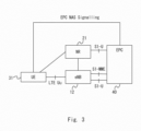
- FIG. 3 is different from Fig. 2 in that S1-U is defined as the reference point used for transmitting user data between the NR 21 and the EPC 40.
- the NR 21 transmits user data transmitted from the UE 31 to the EPC 40 via the S1-U reference point defined between the NR 21 and the EPC 40.
- the EPC 40 sorts and transmits the user data addressed to the UE 31 to the eNB 12 and the NR 21.
- the NR 21 transmits the user data transmitted from the EPC 40 to the UE 31.
- Fig. 4 Security keys applied to user data sent via the NR 21 are described hereinafter with reference to Fig. 4 .
- the description of Fig. 4 uses the gNB 22 as the NR 21.
- the gNB 22 corresponds to a base station used in the NR 21.
- the dotted lines shown between the UE 31 and the eNB 12, between the eNB 12 and the MME 41, between the MME 41 and the S-GW 42 and between the eNB 12 and the gNB 22 indicate that a control message (C(Control)-Plane data) is transmitted.
- the solid lines shown between the UE 31 and the eNB 12, between the UE 31 and the gNB 22, between the eNB 12 and the S-GW 42, and between the gNB 22 and the S-GW 42 indicate that user data U-Plane data) is transmitted.
- a security key K AN is used to protect user data transmitted between the UE 31 and the gNB 22.
- a security key K UP is used to protect user data transmitted between the UE 31 and the S-GW 42.
- the security anchor may be a node device that has a security key that is not transmitted in the radio zone and derives security keys used for encryption or integrity of data that is transmitted in the radio zone, for example.
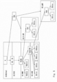
- a hierarchy of security keys used in the communication system including the configuration shown in Fig. 2 or 3 is described hereinafter with reference to Fig. 5 .
- a USIM Universal Subscriber identification Module
- An AuC Authentication Center
- Each of the USIM and the AuC has a security key K.
- the USIM and the AuC derive a cipher key CK and an integrity key IK from the security key K.
- the USIM outputs the cipher key CK and the integrity key IK to the UE 31, and the AuC sends the cipher key CK and the integrity key IK to an HSS (Home Subscriber Server).
- the HSS is a node device that manages subscription information related to the UE.
- the UE 31 and the HSS derive a security key K ASME from the cipher key CK and the integrity key IK.
- the HSS sends the security key K ASME to the MME 41.
- the UE 31 and the MME 41 generate, from the security key K ASME , a security key K NASenc , a security key K NASint , a security key K eNB /NH, and a security key K UP .
- the security key K NASenc is used for encryption of NAS message sent between the UE 31 and the MME 41.
- the security key K NASint is used for integrity of NAS message sent between the UE 31 and the MME 41.
- the MME 41 sends the security key K eNB /NH to the eNB 12, and sends the security key K UP to the S-GW 42.
- the UE 31 and the eNB 12 derive, from the security key K eNB /NH, a security key the K UPint , a security key K UPenc , a security keyK RRCint , and a security keyK RRCenc .
- the security key K UPint is used for encryption of user data.
- the security key K UPenc is used for integrity of user data.
- the security key K RRCenc is used for encryption of RRC (Radio Resource Control) message.
- the security key K RRCint is used for integrity of RRC message.
- the security key K UPenc and the security key K UPint may be derived in the S-GW 42.
- the S-GW 42 may derive the security key K UPenc and the security key K UPint from the security key K UP .
- the security key K UPenc and the security key K UPint may be derived in the gNB 22.
- the gNB 22 may derive the security key K UPenc and the security key K UPint from the security key K AN .
- the eNB 12 may derive the security key K AN from the security key K eNB /NH, and sends the security key K AN to the gNB 22.
- the security key K AN may be derived from the security key K NG .
- the security key K NG may be derived from the security key K.
- the security key K NG may be derived from the cipher key CK and the integrity key IK, or derived from the security key K ASME .
- the security key K NG is a security key used in the NextGen System.
- the security key K UP may be derived from the security keyK eNB /NH. Further, the security key K AN may be derived from the security key K ASME .
- the security key K UPenc and the security key K UPint used in the eNB 12 are different from the security key K UPenc and the security key K UPint used in the gNB 22. Further, the security key K UPenc and the security key K UPint used in the eNB 12 are different from the security key K UPenc and the security key K UPint used in the S-GW 42.
- the security key K UPenc and the security key K UPint used in the eNB 12 may be derived using different parameters from parameters used when deriving the security key K UPenc and the security key K UPint used in the gNB 22 or the S-GW 42.
- the parameters may be an NS (Network Slice) ID for identifying the network slice or the like, for example.
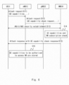
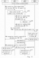
- the initial attach procedure according to the second embodiment is described hereinafter with reference to Fig. 6 .
- the UE 31 sends an Attach request message containing UE capabilities to the eNB 12 (S11).
- the Attach request message may contain the capability and security algorithms related to the NR to be used in the gNB 22.
- the eNB 12 sends the Attach request message containing UE capability check request to the MME 41 (S12).
- the Attach request message sent from the eNB 12 to the MME 41 may contain the capability and security algorithms related to the NR to be used in the gNB 22.
- AKA Authentication and Key Agreement
- NAS security establishment is performed between the UE 31 and the MME 41 (S13).
- security keys are shared between the UE 31 and the MME 41.
- AKA & NAS security establishment may be omitted if already performed.
- the MME 41 then performs UE capabilities and NR subscription check (S14). For example, the MME 41 may acquire and hold subscription information related to the UE from the HSS or another network node, and perform UE capabilities and NR subscription check by using the acquired subscription information.
- the UE capabilities check and NR subscription check may be determining whether the UE 31 is authorized to use a communication technology supported by the UE 31. For example, the MME 41 may determine that some of a plurality of communication technologies supported by the UE 31 are authorized to use. To be specific, the MME 41 may determine whether the UE 31 has the access right to the NR and whether the user of the UE 31 subscribes the service provided by the NR.
- the MME 41 sends Attach response with UE capability check response to the eNB 12, and the eNB 12 sends the Attach response with UE capability check response to the UE 31 (S15).
- the Attach response with UE capability check response may contain information indicating a communication technology which the UE 31 is authorized to use.
- the MME 41 may send an Initial Context setup request message containing the Attach response with UE capability check response to the eNB 12.
- the eNB 12 may send an RRC connection reconfiguration message containing the Attach response with UE capability check response to the UE 31.
- the eNB 12 stores, into a memory or the like, information about the UE capabilities of the UE 31 to access the NR and the access right to the NR granted to the UE 31 (S16).
- the UE capabilities stored into the memory by the eNB 12 may be information containing a certain communication technology authorized to use among one or more communication technologies sent from the UE 31 in Step S11, for example.
- a node e.g., eNB 12 located close to the UE 31 stores information about the UE capabilities to access the NR and the access right to the NR, which enables security processing to be performed easily and more quickly.
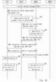
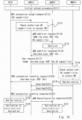
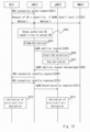
- the dual connectivity procedure is described hereinafter with reference to Fig. 7 .
- the initial attach procedure described in Fig. 6 is performed in the UE 31, the eNB 12 and the MME 41 (S21).
- the UE 31 sends an RRC connection establishment message to the eNB 12 (S22).
- the RRC connection establishment message contains UE req.algo./KDF IDs and UE capability.
- the UE req.algo./KDF IDs are identification information of algorithms used for encryption and integrity and KDF (Key Derivation Function) to be used, which are requested by the UE 31.
- the identification information of algorithms used for encryption and integrity or the like requested by the UE 31 may be, in other words, identification information of algorithms used for encryption and integrity or the like designated by the UE 31.
- the UE req.algo./KDF IDs may contain identification information of a plurality of algorithms and KDFs.
- the UE capability may be information indicating a communication technology that is used by the UE 31 for communication with the gNB 22.
- the eNB 12 checks whether the UE 31 has the UE capability to access the NR and has the access right to the NR. The eNB 12 determines whether the UE capability sent from the UE 31 is contained in the UE capabilities stored in Step S16 of Fig. 6 (S23). Specifically, the eNB 12 determines whether the UE 31 has the UE capability to access the NR before initiating the security processing for selecting a security algorithm suitable for the gNB 22. Further, by checking whether the UE 31 has the access right to the NR, it is possible to avoid access to the NR by the UE with no right to access.
- the eNB 12 determines that the UE capability sent from the UE 31 is contained in the UE capabilities stored in Step S16 of Fig. 6 , the eNB 12 derives the security key K AN (S24).
- the eNB 12 sends a gNB addition request message to the gNB 22 (S25).
- the gNB addition request message contains the security key K AN , the UE req.algo./KDF IDs, and the UE capability.
- the eNB 12 may select the gNB 22 capable of performing dual connectivity based on the UE capability, and send a gNB addition request message to the selected gNB 22.
- the gNB 22 decides an algorithm and KDF to be used for communication with the UE 31 from a plurality of algorithms and KDFs based on the UE capability (S26).
- the algorithm and KDF decided by the gNB 22 are different from the algorithm and KDF requested by the UE 31, the eNB 12 derives K AN by using the algorithm and KDF decided by the gNB 22.
- the gNB 22 sends the derived K AN to the gNB 22.
- the gNB 22 then send a gNB addition response message to the eNB 12 (S27).
- the gNB addition response message contains identification information of the decided algorithm and KDF (decided.algo./KDF IDs).
- the eNB 12 then sends an RRC connection reconfig request message to the UE 31 (S28).
- the RRC connection reconfig request message contains the algorithm and KDF identification information contained in the gNB addition response message.
- KDF ID KDF identification information
- security keys can be derived in the UE 31 and the eNB 12, in the UE 31 and the MME 41 or the like without directly sending security keys between the UE 31 and the eNB 12.
- the UE 31 sends an RRC connection reconfig response message to the eNB 12 (S29).
- the eNB 12 then sends a gNB Reconfiguration complete message to the gNB 22 (S30).
- the UE 31 derives the security key K AN (S31). Further, the UE 31 and the gNB 22 derive the K UPint and K UPenc from the security key K AN . After that, the UE 31 and the gNB 22 activate encryption and decryption (S32, S33).
- Step S42 in Fig. 8 the UE 31 sends, to the eNB 12, an RRC connection establishment message that contains UE capability without containing UE req.algo./KDF IDs.
- Step S45 the eNB 12 sends, to the gNB 22, a gNB addition request message that contains eNB req.algo./KDF IDs, not UE req.algo./KDF IDs.
- identification information of algorithms used for encryption and integrity and KDF (Key Derivation Function) to be used, which are requested or designated by the eNB 12, are contained in the gNB addition request message.
- Steps S61 to S63 are substantially the same as Steps S41 to S43 in Fig. 8 , and therefore detailed description thereof is omitted.
- the eNB 12 sends, to the gNB 22, a gNB addition request message that contains UE capability without containing UE req.algo./KDF IDs and eNB req.algo./KDF IDs (S64).
- the gNB 22 decides an algorithm and KDF to be used for communication with the UE 31 from a plurality of algorithms and KDFs based on the UE capability (S65).
- the gNB 22 then sends a gNB addition response message to the eNB 12 (S27).
- the gNB addition response message contains identification information of the decided algorithm and KDF.
- the eNB 12 then derives the security key K AN (S67).
- the eNB 12 sends the derived security key K AN to the gNB 22 (S68).
- Steps S69 to S74 are substantially the same as Steps S28 to S33 in Fig. 7 , and therefore detailed description thereof is omitted.
- Steps S81 to S83 are substantially the same as Steps S41 to S43 in Fig. 8 , and therefore detailed description thereof is omitted.
- the eNB 12 sends a gNB addition request message to the gNB 22 (S84).
- the gNB addition request message contains UE capability and a security key K eNB .
- the security key K eNB may be the security key K eNB derived in the MME 41, for example, and sent from the MME 41 to the eNB 12 at arbitrary timing before Step S84.
- the gNB 22 decides an algorithm and KDF to be used for communication with the UE 31 from a plurality of algorithms and KDFs based on the UE capability, and further derives the security key K AN from the security key K eNB (S85).
- Steps S86 to S92 are substantially the same as Steps S27 to S33 in Fig. 7 , and therefore detailed description thereof is omitted.
- the gNB 22 that is added to perform dual connectivity can share the security key K AN with the UE 31.
- the UE 31 can establish security and communicate with each of the eNB 12 and the gNB 22.
- a dual connectivity procedure according to a third embodiment is described with reference to Fig. 11 .
- a process where the MME 41 located in the core network derives the security key K AN is described in the third embodiment.
- the UE 31 sends an RRC connection establishment message to the eNB 12 (S102).
- the RRC connection establishment message contains UE req.algo./KDF IDs and UE capability.
- the eNB 12 determines whether the UE capability sent from the UE 31 is contained in the UE capabilities stored in Step S16 of Fig. 6 (S103).
- the eNB 12 sends a gNB addition request message to the gNB 22 (S104).
- the gNB addition request message contains the UE req.algo./KDF IDs and the UE capability.
- the gNB 22 decides an algorithm and KDF to be used for communication with the UE 31 from a plurality of algorithms and KDFs based on the UE capability (S105).
- the gNB 22 then sends a gNB addition response message to the eNB 12 (S106).
- the gNB addition response message contains identification information of the decided algorithm and KDF (decided.algo./KDF IDs).
- the eNB 12 sends a Key request message to the MME 41 in order to request derivation of the security key K AN (S107).
- the Key request message contains the security key K eNB , the decided algorithm and KDF identification information (decided.algo./KDF IDs), and the UE capability.
- the MME 41 determines whether the UE capability contained in the Key request message is contained in the UE capabilities, just like the eNB 12 did in Step S103 (S108). Note that the processing of Step S108 may be omitted.
- the MME 41 may acquire the UE capabilities from the HSS, for example. Further, the MME 41 may proceed to the next step S109 without carrying out Step S108.
- the MME 41 derives the security key K AN from the security key K eNB contained in the Key request message (S109).
- the eNB 12 does not necessarily add the security key K eNB in the Key request message in Step S107.
- the eNB 12 After sending the Key request message to the UE 31 in Step S107, the eNB 12 sends an RRC connection reconfig request message to the UE 31 (S1 10).
- the RRC connection reconfig request message contains the algorithm and KDF identification information contained in the gNB addition response message.
- the MME 41 After deriving the security key K AN , the MME 41 sends the security key K AN to the eNB 12 (S111). Then, the eNB 12 sends the received security key K AN to the gNB 22 (S112). If direct communication is possible between the MME 41 and the gNB 22, the MME 41 may directly send the security key K AN to the gNB 22.
- Steps S113 to S117 are substantially the same as Steps S29 to S33 in Fig. 7 , and therefore detailed description thereof is omitted.
- Step S112 of Fig. 12 the UE 31 sends, to the eNB 12, an RRC connection establishment message that contains UE capability without containing UE req.algo./KDF IDs.
- Step S114 the eNB 12 sends, to the gNB 22, a gNB addition request message that contains eNB req.algo./KDF IDs, not UE req.algo./KDF IDs.
- identification information of algorithms used for encryption and integrity and KDF (Key Derivation Function) to be used, which are requested or designated by the eNB 12, are contained in the gNB addition request message.
- Steps S131 to S133 are substantially the same as Steps S111 to S113 in Fig. 12 , and therefore detailed description thereof is omitted.
- the eNB 12 sends, to the gNB 22, a gNB addition request message that contains UE capability without containing UE req.algo./KDF IDs and eNB req.algo./KDF IDs (S134).
- the gNB 22 decides an algorithm and KDF to be used for communication with the UE 31 from a plurality of algorithms and KDFs based on the UE capability (S135).
- the gNB 22 then sends a gNB addition response message to the eNB 12 (S136).
- the gNB addition response message contains identification information of the decided algorithm and KDF.
- Steps S137 to S147 are substantially the same as Steps S117 to S127 in Fig. 12 , and therefore detailed description thereof is omitted.
- Steps S151 to S153 are substantially the same as Steps S111 to S113 in Fig. 12 , and therefore detailed description thereof is omitted.
- the eNB 12 sends a gNB addition request message to the MME 41 (S154).
- the gNB addition request message contains the security key K eNB and the UE capability.
- Step S155 is substantially the same as Step S108 in Fig. 11 , and therefore detailed description thereof is omitted.
- the MME 41 decides an algorithm and KDF to be used for communication with the UE 31 from a plurality of algorithms and KDFs based on the UE capability. Further, the MME 41 derives the security key K AN from the security key K eNB contained in the Key request message (S156). When the security key K AN is derived from the security key K ASME , the eNB 12 does not necessarily add the security key K eNB in the Key request message in Step S154.
- the MME 41 sends the security key K AN and identification information of the decided algorithm and KDF (decided.algo./KDF IDs) to the eNB 12 (S157).
- the eNB 12 then sends the security key K AN to the gNB 22 (S158).
- the eNB 12 sends an RRC connection reconfig request message to the UE 31.
- the RRC connection reconfig request message contains the decided algorithm and KDF identification information (decided.algo./KDF IDs).
- Steps S160 to S164 are substantially the same as Steps S113 to S117 in Fig. 1 , and therefore detailed description thereof is omitted.
- FIG. 15 A dual connectivity procedure in the case where the S-GW 42 is used as a security anchor is described hereinafter with reference to Fig. 15 .
- Fig. 15 a process where the S-GW 42 located in the core network derives a security key K UP is described.
- Steps S171 to S174 are substantially the same as Steps S101 to S104 in Fig. 11 , and therefore detailed description thereof is omitted.
- the gNB 22 sends, to the S-GW 42, the identification information of UE req.algo./KDF IDs and the UE capability received from the eNB 12 and K ASME (S175).
- K ASME may be sent from the MME 41 to the S-GW 42.
- the S-GW 42 decides an algorithm and KDF to be used for communication with the UE 31 from a plurality of algorithms based on the UE capability (S176). Further, in Step S176, the S-GW 42 derives the security key K UP from the security key K ASME .
- the S-GW 42 sends identification information of the decided algorithm and KDF (decided.algo./KDF IDs) to the MME 41 (S177). Further, the MME 41 sends the identification information of the decided algorithm and KDF to the gNB 22 and the eNB 12 (S178, S179).
- Steps S180 to S185 are substantially the same as Step S110 and Steps S113 to S117 in Fig. 11 , and therefore detailed description thereof is omitted. Note that, while the gNB 22 activates encryption and integrity in Step S117 of Fig. 11 , the S-GW 42 activates encryption and integrity in Step S185 of Fig. 15 (S32, S33).
- the gNB 22 that is added to perform dual connectivity can acquire the security key K AN generated in the MME 41.
- the gNB 22 can thereby share the security key K AN with the UE 31.
- the UE 31 can establish security and communicate with each of the eNB 12 and the gNB 22.
- the UE network capability is contained in an Attach request message sent from the UE 31 in the initial attach procedure.
- the UE network capability contains an algorithm for encryption and an algorithm for integrity used in the NR, for example.
- new algorithms for the NR are added to the UE network capability IE in order to send the algorithms in the Attach request.
- the algorithm for encryption and the algorithm for integrity are identified by 4-digit binary numbers and algorithm names.
- the algorithm for encryption may be represented as: "0000 2 ":NEA0, "0001 2 ":NEA1, "0010 2 ":NEA2, “0011 2 ":NEA3 and the like.
- the algorithm for integrity may be represented as: "0000 2 ":NIA0, "0001 2 ":NIA1, "0010 2 ":NIA2, “0011 2 “:NIA3 and the like.
- information indicating whether the UE 31 has NR capability to access NR is set to ocetet 9 and bit 3, for example.
- the algorithm (NEA0-NEA7) for encryption supported by the UE 31 is shown in octet 10 and bit 1-8.
- the algorithm (NIA0-NIA7) for integrity supported by the UE 31 is shown in octet 11 and bit 1-8.
- the algorithm for encryption shown in octet 10 and the algorithm for integrity shown in octet 11 are algorithms used in the NR or 5GS (5G System). For example, when 1 is set to each bit, it means that the UE 31 supports the algorithm associated with this bit, and when 0 is set, it means that the UE 31 does not support the algorithm associated with this bit.
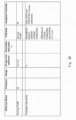
- Fig. 17 shows that the MME 41 and the HSS have NR Subscription, UE NR Capability, Selected NR Security Algorithm, and UE NR Security Algorithm Preference as the NR capability and the Subscription information related to NR.
- the NR subscription IE is added for the MME 41 and the HSS to store this NR subscription IE.
- the NR Subscription indicates information as to whether the user of the UE 31 subscribes the service involving access to NR.
- the UE NR Capability contains security algorithms and key derivation functions supported by the UE 31.
- the Selected NR Security Algorithm indicates the selected NR Security Algorithm.
- the UE NR Security Algorithm Preference indicates Preference information related to NR security algorithm and key derivation functions.
- the UE NR Capability may be included in another Field stored in the MME 41 and the HSS, and it may be included in UE Radio Access Capability, UE Network Capability, or MS Network Capability, for example.
- the NR Subscription may be also included in another Field stored in the MME 41 and the HSS, and it may be included in Access Restriction or EPS Subscribed Charging Characteristics, for example.
- information indicating RATs such as NR or NG-RAN is added to the Access Restriction in order to indicate whether or not the UE 31 is authorized to use the NR.
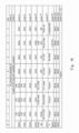
- a format of UE security capability according to the fourth embodiment is described hereinafter with reference to Fig. 18 .
- the UE security capability is contained in an Initial Context setup request message sent from the MME 41 in the initial attach procedure.
- the algorithm (NEA0-NEA7) for encryption supported by the UE 31 is shown in octet 8 and bit 1-8.
- the algorithm (NIA0-NIA7) for integrity supported by the UE 31 is shown in octet 9 and bit 1-8.
- the algorithm for encryption shown in octet 8 and the algorithm for integrity shown in octet 9 are algorithms used in NR or 5GS (5G System). In other words, new algorithms for the NR are added to the UE security capability IE in order to send the new algorithms for the NR in the Initial context setup request.
- the Initial Context setup request message contains UE NR capabilities and NR subscription.
- the NR Subscription may be contained in the Handover Restriction List IE shown in Fig. 20 .
- information indicating RATs such as NR or NG-RAN is added to the Handover Restriction List IE in order to indicate whether or not the UE 31 is authorized to use the NR.
- the dual connectivity procedure according to the fourth embodiment is described hereinafter with reference to Fig. 21 .
- the eNB 12 operates as Master eNB
- the gNB 22 operates as Secondary gNB.
- the UE 31 establishes RRC connection with the eNB 12 (S201).
- Step S202 carries out one of Method 1 where the eNB 12 requests the UE 31 to provide UE's capability and NR Subscription and Method 2 where the eNB 12 requests the MME 41 to provide UE's capability and NR Subscription. Method 1 and Method 2 are described in detail later.
- the UE's capability may be UE NR Capability, for example.
- the eNB 12 checks the UE's capability and the NR Subscription (S203). When the eNB 12 determines that the UE 31 has the capability to access the NR and further has the access right to the NR, it proceeds to the next Step. Otherwise, if another eNB, not the gNB 22, is available, the eNB 12 carries out processing to perform dual connectivity with this eNB. A process in the case where the eNB 12 determines that the UE 31 has the capability to access the NR and also has the access right to the NR is described hereinbelow.
- the eNB 12 derives the security key S-K gNB from the security key K eNB (S204).
- the security key S-K gNB is used for integrity and confidentiality protection in the gNB 22.
- the security key S-K gNB corresponds to the security key K AN in Fig. 5 , for example.
- the eNB 12 sends an SgNB addition request message to the gNB 22 (S205).
- the SgNB addition request message contains the security key S-K gNB and the UE NR Capability containing security algorithms.
- the gNB 22 decides security algorithms to be used for integrity and confidentiality protection based on the UE NR Capability (S206). Then, the eNB 12 derives security keys to be used for integrity and confidentiality protection from the security key S-K gNB .
- the security keys derived by the eNB 12 include a key for integrity and confidentiality protection related to SRB (Signalling Radio Bearer) (e.g., K RRCint and K RRCenc ) and a key for integrity and confidentiality protection related to DRB (Data Radio Bearer) (e.g., K UPint and K UPenc ), for example.
- the gNB 22 then sends an SgNB addition request Acknowledge message to the eNB 12 (S208).
- the SgNB addition request Acknowledge message contains the security algorithms decided in the gNB 22.
- the eNB 12 sends an RRC connection reconfig request message to the UE 31 (S209).
- the RRC connection reconfig request message contains the security algorithms decided in the gNB 22.
- the UE 31 then sends an RRC connection reconfig response message to the eNB 12 (S210).
- the eNB 12 then sends an SgNB Reconfiguration complete message to the gNB 22 (S211). After that, the UE 31 and the gNB 22 activate encryption and decryption (S212, S213).
- Step S202 of Fig. 21 is described hereinafter with reference to Fig. 22 .
- the eNB 12 sends a UE Capability Enquiry message to the UE 31 in order to make a request for UE's capability (UE NR capability) to the UE 31 (S221).
- the UE 31 then sends an UE Capability Information message to the eNB 12 (S222).
- the UE Capability Enquiry message and the UE Capability Information message contain Security Algorithm Config IE.
- the UE 31 adds UE's capability, which is security algorithms, to the Security Algorithm Config IE.
- the eNB 12 sends a UE Capability Request message to the MME 41 in order to make a request for UE's capability (UE NR capability) to the MME 41 (S231).
- the MME 41 then sends an UE Capability Response message to the eNB 12 (S232).
- the eNB 12 adds, to the UE Capability Request message, IE related to information needed to be acquired among UE network capability, UE security capability, NR Subscription, UE NR Capability, Selected NR Security Algorithm, and UE NR Security Algorithm Preference.
- the MME 41 adds the information requested by the eNB 12 in the UE Capability Response message.
- Fig. 24 shows derivation of the security key K AN using KDF.
- the security key K eNB K ASME
- SCG Counter KDF ID
- NR ID NR ID
- Slice ID and Session ID
- K AN K UPint
- K UPenc K UPint
- K UPenc K UPint
- K UPenc K UPint
- K UPenc K UPint and K UPenc .
- the NR ID is identification information indicating a communication technology available in the UE 31.
- the NR ID is contained in the UE capability, for example.
- the Slice ID and Session ID may be also contained in the UE capability.
- Fig. 25 shows derivation of the security key K UP using KDF.
- the security key K eNB K ASME
- SCG Counter KDF ID
- NR ID NR ID
- Slice ID Session ID
- Session ID Session ID
- the present disclosure is described as a hardware configuration in the above embodiments, it is not limited thereto.
- the present disclosure may be implemented by causing a CPU (Central Processing Unit) to execute a computer program to perform processing in the UE and each device.
- a CPU Central Processing Unit
- the program can be stored and provided to the computer using any type of non-transitory computer readable medium.
- the non-transitory computer readable medium includes any type of tangible storage medium. Examples of the non-transitory computer readable medium include magnetic storage media (such as floppy disks, magnetic tapes, hard disk drives, etc.), optical magnetic storage media (e.g.
- CD-ROM Read Only Memory
- CD-R CD-R/W
- DVD-ROM Digital Versatile Disc Read Only Memory
- DVD-R DVD Recordable
- DVD-R DL DVD-R Dual Layer
- DVD-RW DVD Rewritable
- DVD-RAM DVD+R
- BD-R Bo-ray (registered trademark) Disc Recordable)
- BD-RE Blu-ray (registered trademark) Disc Rewritable)
- BD-ROM semiconductor memories
- semiconductor memories such as mask ROM, PROM (Programmable ROM), EPROM (Erasable PROM), flash ROM, RAM (Random Access Memory), etc.
- the program may be provided to a computer using any type of transitory computer readable medium.
- Examples of the transitory computer readable medium include electric signals, optical signals, and electromagnetic waves.
- the transitory computer readable medium can provide the program to a computer via a wired communication line such as an electric wire or optical fiber or a wireless communication line.
Claims (3)
- Système comprenant :un eNB (12) ;un gNB (22) ; etune entité de gestion de mobilité, MME (41), dans lequella MME (41) est configurée pourenvoyer, à l'eNB (12), un abonnement NR dans le cadre d'une liste de restrictions de transfert intercellulaire et d'une capacité NR d'UE; etl'eNB (12) est configuré pour déterminer s'il faut établir une double connectivité avec le gNB (22) pour le terminal (31) en vérifiant si le terminal (31) a une capacité pour le gNB (22) et est autorisé à accéder au gNB (22) sur la base de l'abonnement NR et de la capacité NR d'UE après que le terminal (31) et l'eNB(12) aient établi une connexion de commande de ressources radio, RRC.
- Noeud eNB (12) comprenant un processeur configuré pour :recevoir, à partir d'une entité de gestion de mobilité, MME (41), un abonnement NRdans le cadre d'une liste de restrictions de transfert intercellulaire et d'une capacité NR d'UE ; etdéterminer s'il faut établir une double connectivité avec le gNB (22) pour le terminal (31) en vérifiant si le terminal (31) a une capacité pour le gNB (22) et est autorisé à accéder au gNB (22) sur la base de l'abonnement NR et de la capacité NR d'UE après que le terminal (31) et l'eNB (12) aient établi une connexion de commande de ressources radio, RRC.
- Procédé réalisé par un eNB (12), le procédé comprenant :la réception (S202, S232), à partir d'une entité de gestion de mobilité, MME (41), d'un abonnement NR dans le cadre d'une liste de restrictions de transfert intercellulaire et d'une capacité NR d'UE ; etla détermination (S203) s'il faut établir une double connectivité avec le gNB (22) pour le terminal (31) en vérifiant si le terminal (31) a une capacité pour le gNB (22) et est autorisé à accéder au gNB (22) sur la base de l'abonnement NR et la capacité NR d'UE après que le terminal (31) et l'eNB (12) aient établi (S201) une connexion de commande de ressources radio, RRC.
Applications Claiming Priority (3)
| Application Number | Priority Date | Filing Date | Title |
|---|---|---|---|
| IN201611036776 | 2016-10-26 | ||
| IN201711014793 | 2017-04-26 | ||
| PCT/JP2017/038824 WO2018079692A1 (fr) | 2016-10-26 | 2017-10-26 | Système de communication , station de base, procédé de commande, et support lisible par ordinateur |
Publications (3)
| Publication Number | Publication Date |
|---|---|
| EP3534633A1 EP3534633A1 (fr) | 2019-09-04 |
| EP3534633A4 EP3534633A4 (fr) | 2019-09-04 |
| EP3534633B1 true EP3534633B1 (fr) | 2023-11-29 |
Family
ID=62023644
Family Applications (1)
| Application Number | Title | Priority Date | Filing Date |
|---|---|---|---|
| EP17863947.2A Active EP3534633B1 (fr) | 2016-10-26 | 2017-10-26 | Système de communication , station de base et procédé de commande |
Country Status (4)
| Country | Link |
|---|---|
| US (1) | US20190254097A1 (fr) |
| EP (1) | EP3534633B1 (fr) |
| JP (1) | JP6904363B2 (fr) |
| WO (1) | WO2018079692A1 (fr) |
Families Citing this family (7)
| Publication number | Priority date | Publication date | Assignee | Title |
|---|---|---|---|---|
| US11122427B2 (en) * | 2017-09-26 | 2021-09-14 | Telefonaktiebolaget Lm Ericsson (Publ) | Managing security contexts and performing key derivation at handover in a wireless communication system |
| US11252628B2 (en) * | 2018-01-09 | 2022-02-15 | Htc Corporation | Device and method for handling new radio capabilities |
| WO2019242545A1 (fr) * | 2018-06-21 | 2019-12-26 | Huawei Technologies Co., Ltd. | Procédé et appareil de négociation d'algorithme de sécurité |
| CN110636556B (zh) * | 2018-06-22 | 2024-02-20 | 中兴通讯股份有限公司 | 网络处理方法、装置、核心网、基站和可读存储介质 |
| CN110740023B (zh) * | 2018-07-20 | 2022-04-29 | 中兴通讯股份有限公司 | 控制信令的发送方法及装置、服务基站、存储介质 |
| KR102604283B1 (ko) * | 2018-10-05 | 2023-11-20 | 삼성전자주식회사 | 정보 보안을 위한 장치 및 방법 |
| WO2021208040A1 (fr) * | 2020-04-16 | 2021-10-21 | Qualcomm Incorporated | Message de demande attach (rattachement) permettant d'indiquer un support dcnr désactivé |
Family Cites Families (8)
| Publication number | Priority date | Publication date | Assignee | Title |
|---|---|---|---|---|
| US8078171B2 (en) * | 2007-06-15 | 2011-12-13 | Intel Corporation | Handoff of a mobile station from a first to a second type of wireless network |
| JP4963453B2 (ja) * | 2007-08-21 | 2012-06-27 | 株式会社エヌ・ティ・ティ・ドコモ | 無線通信システム、無線通信方法及び無線端末 |
| CN102612840B (zh) * | 2009-11-06 | 2016-03-02 | 株式会社Ntt都科摩 | 移动通信系统、无线控制装置、核心网络装置、移动通信终端及移动通信方法 |
| EP2896265B1 (fr) * | 2012-09-14 | 2020-09-02 | Interdigital Patent Holdings, Inc. | Perfectionnements apportés à un système pour permettre le transfert non 3gpp dans le 3gpp |
| US10075888B2 (en) * | 2014-09-25 | 2018-09-11 | Qualcomm Incorporated | Service-specific air-interface selection |
| WO2016120052A1 (fr) * | 2015-01-30 | 2016-08-04 | Nokia Solutions And Networks Oy | Procédé, appareil et système de transfert de connectivité double |
| EP3497971B1 (fr) * | 2016-11-04 | 2022-03-16 | Samsung Electronics Co., Ltd. | Procédé et appareil pour fournir la meme qualité de service dans la liaison montante que dans la liaison descendente |
| EP3713370A1 (fr) * | 2019-03-19 | 2020-09-23 | Comcast Cable Communications Management, LLC | Communications sans fil pour configuration/réponse de communication |
-
2017
- 2017-10-26 JP JP2018547769A patent/JP6904363B2/ja active Active
- 2017-10-26 EP EP17863947.2A patent/EP3534633B1/fr active Active
- 2017-10-26 WO PCT/JP2017/038824 patent/WO2018079692A1/fr unknown
- 2017-10-26 US US16/345,458 patent/US20190254097A1/en active Pending
Non-Patent Citations (2)
| Title |
|---|
| ERICSSON: "X2AP TP for bearer harmonisation", vol. RAN WG3, no. Prague, Czech Republic; 20171009 - 20171013, 29 September 2017 (2017-09-29), XP051356446, Retrieved from the Internet <URL:http://www.3gpp.org/ftp/tsg_ran/WG3_Iu/TSGR3_97bis/Docs/> [retrieved on 20170929] * |
| NEC: "pCR to TR 33.899: Proposal of key issue and solution for option 3", vol. SA WG3, no. Santa Cruz de Tenerife, Spain; 20161107 - 20161111, 18 November 2016 (2016-11-18), XP051187578, Retrieved from the Internet <URL:http://www.3gpp.org/ftp//tsg_sa/WG3_Security/TSGS3_85_Santa_Cruz/Docs/> [retrieved on 20161118] * |
Also Published As
| Publication number | Publication date |
|---|---|
| WO2018079692A1 (fr) | 2018-05-03 |
| EP3534633A1 (fr) | 2019-09-04 |
| JP6904363B2 (ja) | 2021-07-14 |
| US20190254097A1 (en) | 2019-08-15 |
| EP3534633A4 (fr) | 2019-09-04 |
| JPWO2018079692A1 (ja) | 2019-09-19 |
Similar Documents
| Publication | Publication Date | Title |
|---|---|---|
| EP3534633B1 (fr) | Système de communication , station de base et procédé de commande | |
| EP3534644B1 (fr) | Noeud source de réseau d'accès radio, terminal de communication et procédés de communication correspondants | |
| CN107925879B (zh) | 一种基于蜂窝接入网络节点的网络接入标识符的认证方法 | |
| US9445443B2 (en) | Network based provisioning of UE credentials for non-operator wireless deployments | |
| US10454686B2 (en) | Method, apparatus, and system for providing encryption or integrity protection in a wireless network | |
| KR102315881B1 (ko) | 사용자 단말과 진화된 패킷 코어 간의 상호 인증 | |
| AU2018261590B2 (en) | Privacy indicators for controlling authentication requests | |
| US20200329372A1 (en) | Key derivation method, communication system, communication terminal, and communication device | |
| US9253811B2 (en) | Network-assisted device-to-device communication | |
| KR101629118B1 (ko) | 융합된 무선 네트워크에서의 인증을 위한 방법 및 장치 | |
| US11799838B2 (en) | Cross-interface correlation of traffic | |
| KR20200003108A (ko) | 키 생성 방법, 사용자 장비, 장치, 컴퓨터 판독가능 저장 매체, 및 통신 시스템 | |
| US8990555B2 (en) | Centralized key management | |
| EP2854329B1 (fr) | Procédé, système et dispositif pour l'établissement d'une connexion sécurisée à un réseau local sans fil | |
| US11153751B2 (en) | Communication system, subscriber-information management apparatus, information acquisition method, non-transitory computer-readable medium, and communication terminal | |
| US20160006726A1 (en) | Using cookies to identify security contexts for connectionless service | |
| EP3534668A1 (fr) | Système de communication, dispositif réseau, procédé d'authentification, terminal de communication et dispositif de sécurité | |
| KR102209289B1 (ko) | 이동 통신 시스템 환경에서 프록시미티 기반 서비스를 위한 보안 및 정보 지원 방법 및 시스템 | |
| US11910480B2 (en) | Systems and methods for null-scheme access authorization | |
| CN112654043A (zh) | 注册方法及装置 | |
| EP4038853A1 (fr) | Authentification de réseau de télécommunications sans fil | |
| CN117812574A (zh) | 通信方法和通信装置 | |
| CN117062070A (zh) | 一种通信方法及通信装置 |
Legal Events
| Date | Code | Title | Description |
|---|---|---|---|
| STAA | Information on the status of an ep patent application or granted ep patent |
Free format text: STATUS: THE INTERNATIONAL PUBLICATION HAS BEEN MADE |
|
| PUAI | Public reference made under article 153(3) epc to a published international application that has entered the european phase |
Free format text: ORIGINAL CODE: 0009012 |
|
| STAA | Information on the status of an ep patent application or granted ep patent |
Free format text: STATUS: REQUEST FOR EXAMINATION WAS MADE |
|
| 17P | Request for examination filed |
Effective date: 20190523 |
|
| A4 | Supplementary search report drawn up and despatched |
Effective date: 20190719 |
|
| AK | Designated contracting states |
Kind code of ref document: A1 Designated state(s): AL AT BE BG CH CY CZ DE DK EE ES FI FR GB GR HR HU IE IS IT LI LT LU LV MC MK MT NL NO PL PT RO RS SE SI SK SM TR |
|
| AX | Request for extension of the european patent |
Extension state: BA ME |
|
| DAV | Request for validation of the european patent (deleted) | ||
| DAX | Request for extension of the european patent (deleted) | ||
| STAA | Information on the status of an ep patent application or granted ep patent |
Free format text: STATUS: EXAMINATION IS IN PROGRESS |
|
| 17Q | First examination report despatched |
Effective date: 20210630 |
|
| STAA | Information on the status of an ep patent application or granted ep patent |
Free format text: STATUS: EXAMINATION IS IN PROGRESS |
|
| REG | Reference to a national code |
Ref document number: 602017077082 Country of ref document: DE Ref country code: DE Ref legal event code: R079 Free format text: PREVIOUS MAIN CLASS: H04W0012040000 Ipc: H04W0012041000 |
|
| GRAP | Despatch of communication of intention to grant a patent |
Free format text: ORIGINAL CODE: EPIDOSNIGR1 |
|
| STAA | Information on the status of an ep patent application or granted ep patent |
Free format text: STATUS: GRANT OF PATENT IS INTENDED |
|
| RIC1 | Information provided on ipc code assigned before grant |
Ipc: H04W 12/041 20210101AFI20230508BHEP |
|
| INTG | Intention to grant announced |
Effective date: 20230609 |
|
| GRAS | Grant fee paid |
Free format text: ORIGINAL CODE: EPIDOSNIGR3 |
|
| GRAA | (expected) grant |
Free format text: ORIGINAL CODE: 0009210 |
|
| STAA | Information on the status of an ep patent application or granted ep patent |
Free format text: STATUS: THE PATENT HAS BEEN GRANTED |
|
| AK | Designated contracting states |
Kind code of ref document: B1 Designated state(s): AL AT BE BG CH CY CZ DE DK EE ES FI FR GB GR HR HU IE IS IT LI LT LU LV MC MK MT NL NO PL PT RO RS SE SI SK SM TR |
|
| REG | Reference to a national code |
Ref country code: GB Ref legal event code: FG4D |
|
| REG | Reference to a national code |
Ref country code: CH Ref legal event code: EP |
|
| REG | Reference to a national code |
Ref country code: DE Ref legal event code: R096 Ref document number: 602017077082 Country of ref document: DE |
|
| REG | Reference to a national code |
Ref country code: IE Ref legal event code: FG4D |
|
| REG | Reference to a national code |
Ref country code: LT Ref legal event code: MG9D |
|
| REG | Reference to a national code |
Ref country code: NL Ref legal event code: MP Effective date: 20231129 |
|
| PG25 | Lapsed in a contracting state [announced via postgrant information from national office to epo] |
Ref country code: GR Free format text: LAPSE BECAUSE OF FAILURE TO SUBMIT A TRANSLATION OF THE DESCRIPTION OR TO PAY THE FEE WITHIN THE PRESCRIBED TIME-LIMIT Effective date: 20240301 |
|
| PG25 | Lapsed in a contracting state [announced via postgrant information from national office to epo] |
Ref country code: IS Free format text: LAPSE BECAUSE OF FAILURE TO SUBMIT A TRANSLATION OF THE DESCRIPTION OR TO PAY THE FEE WITHIN THE PRESCRIBED TIME-LIMIT Effective date: 20240329 |
|
| PG25 | Lapsed in a contracting state [announced via postgrant information from national office to epo] |
Ref country code: LT Free format text: LAPSE BECAUSE OF FAILURE TO SUBMIT A TRANSLATION OF THE DESCRIPTION OR TO PAY THE FEE WITHIN THE PRESCRIBED TIME-LIMIT Effective date: 20231129 |
|
| PG25 | Lapsed in a contracting state [announced via postgrant information from national office to epo] |
Ref country code: ES Free format text: LAPSE BECAUSE OF FAILURE TO SUBMIT A TRANSLATION OF THE DESCRIPTION OR TO PAY THE FEE WITHIN THE PRESCRIBED TIME-LIMIT Effective date: 20231129 |
|
| PG25 | Lapsed in a contracting state [announced via postgrant information from national office to epo] |
Ref country code: LT Free format text: LAPSE BECAUSE OF FAILURE TO SUBMIT A TRANSLATION OF THE DESCRIPTION OR TO PAY THE FEE WITHIN THE PRESCRIBED TIME-LIMIT Effective date: 20231129 Ref country code: IS Free format text: LAPSE BECAUSE OF FAILURE TO SUBMIT A TRANSLATION OF THE DESCRIPTION OR TO PAY THE FEE WITHIN THE PRESCRIBED TIME-LIMIT Effective date: 20240329 Ref country code: GR Free format text: LAPSE BECAUSE OF FAILURE TO SUBMIT A TRANSLATION OF THE DESCRIPTION OR TO PAY THE FEE WITHIN THE PRESCRIBED TIME-LIMIT Effective date: 20240301 Ref country code: ES Free format text: LAPSE BECAUSE OF FAILURE TO SUBMIT A TRANSLATION OF THE DESCRIPTION OR TO PAY THE FEE WITHIN THE PRESCRIBED TIME-LIMIT Effective date: 20231129 Ref country code: BG Free format text: LAPSE BECAUSE OF FAILURE TO SUBMIT A TRANSLATION OF THE DESCRIPTION OR TO PAY THE FEE WITHIN THE PRESCRIBED TIME-LIMIT Effective date: 20240229 |