EP3534427A1 - Battery pack, and electric appliance using battery pack - Google Patents
Battery pack, and electric appliance using battery pack Download PDFInfo
- Publication number
- EP3534427A1 EP3534427A1 EP17865658.3A EP17865658A EP3534427A1 EP 3534427 A1 EP3534427 A1 EP 3534427A1 EP 17865658 A EP17865658 A EP 17865658A EP 3534427 A1 EP3534427 A1 EP 3534427A1
- Authority
- EP
- European Patent Office
- Prior art keywords
- battery pack
- terminal
- electric appliance
- voltage
- appliance body
- Prior art date
- Legal status (The legal status is an assumption and is not a legal conclusion. Google has not performed a legal analysis and makes no representation as to the accuracy of the status listed.)
- Withdrawn
Links
Images














Classifications
-
- H—ELECTRICITY
- H01—ELECTRIC ELEMENTS
- H01M—PROCESSES OR MEANS, e.g. BATTERIES, FOR THE DIRECT CONVERSION OF CHEMICAL ENERGY INTO ELECTRICAL ENERGY
- H01M10/00—Secondary cells; Manufacture thereof
- H01M10/42—Methods or arrangements for servicing or maintenance of secondary cells or secondary half-cells
- H01M10/4207—Methods or arrangements for servicing or maintenance of secondary cells or secondary half-cells for several batteries or cells simultaneously or sequentially
-
- H—ELECTRICITY
- H02—GENERATION; CONVERSION OR DISTRIBUTION OF ELECTRIC POWER
- H02J—ELECTRIC POWER NETWORKS; CIRCUIT ARRANGEMENTS OR SYSTEMS FOR SUPPLYING OR DISTRIBUTING ELECTRIC POWER; SYSTEMS FOR STORING ELECTRIC ENERGY
- H02J7/00—Circuit arrangements for charging or discharging batteries or for supplying loads from batteries
- H02J7/50—Circuit arrangements for charging or discharging batteries or for supplying loads from batteries acting upon multiple batteries simultaneously or sequentially
- H02J7/575—Parallel/serial switching of connection of batteries to charge or load circuit
-
- B—PERFORMING OPERATIONS; TRANSPORTING
- B25—HAND TOOLS; PORTABLE POWER-DRIVEN TOOLS; MANIPULATORS
- B25F—COMBINATION OR MULTI-PURPOSE TOOLS NOT OTHERWISE PROVIDED FOR; DETAILS OR COMPONENTS OF PORTABLE POWER-DRIVEN TOOLS NOT PARTICULARLY RELATED TO THE OPERATIONS PERFORMED AND NOT OTHERWISE PROVIDED FOR
- B25F5/00—Details or components of portable power-driven tools not particularly related to the operations performed and not otherwise provided for
-
- H—ELECTRICITY
- H01—ELECTRIC ELEMENTS
- H01M—PROCESSES OR MEANS, e.g. BATTERIES, FOR THE DIRECT CONVERSION OF CHEMICAL ENERGY INTO ELECTRICAL ENERGY
- H01M50/00—Constructional details or processes of manufacture of the non-active parts of electrochemical cells other than fuel cells, e.g. hybrid cells
- H01M50/20—Mountings; Secondary casings or frames; Racks, modules or packs; Suspension devices; Shock absorbers; Transport or carrying devices; Holders
- H01M50/247—Mountings; Secondary casings or frames; Racks, modules or packs; Suspension devices; Shock absorbers; Transport or carrying devices; Holders specially adapted for portable devices, e.g. mobile phones, computers, hand tools or pacemakers
-
- H—ELECTRICITY
- H01—ELECTRIC ELEMENTS
- H01M—PROCESSES OR MEANS, e.g. BATTERIES, FOR THE DIRECT CONVERSION OF CHEMICAL ENERGY INTO ELECTRICAL ENERGY
- H01M50/00—Constructional details or processes of manufacture of the non-active parts of electrochemical cells other than fuel cells, e.g. hybrid cells
- H01M50/50—Current conducting connections for cells or batteries
- H01M50/502—Interconnectors for connecting terminals of adjacent batteries; Interconnectors for connecting cells outside a battery casing
- H01M50/519—Interconnectors for connecting terminals of adjacent batteries; Interconnectors for connecting cells outside a battery casing comprising printed circuit boards [PCB]
-
- H—ELECTRICITY
- H02—GENERATION; CONVERSION OR DISTRIBUTION OF ELECTRIC POWER
- H02J—ELECTRIC POWER NETWORKS; CIRCUIT ARRANGEMENTS OR SYSTEMS FOR SUPPLYING OR DISTRIBUTING ELECTRIC POWER; SYSTEMS FOR STORING ELECTRIC ENERGY
- H02J7/00—Circuit arrangements for charging or discharging batteries or for supplying loads from batteries
-
- H—ELECTRICITY
- H01—ELECTRIC ELEMENTS
- H01M—PROCESSES OR MEANS, e.g. BATTERIES, FOR THE DIRECT CONVERSION OF CHEMICAL ENERGY INTO ELECTRICAL ENERGY
- H01M2220/00—Batteries for particular applications
-
- H—ELECTRICITY
- H01—ELECTRIC ELEMENTS
- H01M—PROCESSES OR MEANS, e.g. BATTERIES, FOR THE DIRECT CONVERSION OF CHEMICAL ENERGY INTO ELECTRICAL ENERGY
- H01M2220/00—Batteries for particular applications
- H01M2220/30—Batteries in portable systems, e.g. mobile phone, laptop
-
- H—ELECTRICITY
- H01—ELECTRIC ELEMENTS
- H01M—PROCESSES OR MEANS, e.g. BATTERIES, FOR THE DIRECT CONVERSION OF CHEMICAL ENERGY INTO ELECTRICAL ENERGY
- H01M50/00—Constructional details or processes of manufacture of the non-active parts of electrochemical cells other than fuel cells, e.g. hybrid cells
- H01M50/20—Mountings; Secondary casings or frames; Racks, modules or packs; Suspension devices; Shock absorbers; Transport or carrying devices; Holders
- H01M50/204—Racks, modules or packs for multiple batteries or multiple cells
- H01M50/207—Racks, modules or packs for multiple batteries or multiple cells characterised by their shape
- H01M50/213—Racks, modules or packs for multiple batteries or multiple cells characterised by their shape adapted for cells having curved cross-section, e.g. round or elliptic
-
- H—ELECTRICITY
- H01—ELECTRIC ELEMENTS
- H01M—PROCESSES OR MEANS, e.g. BATTERIES, FOR THE DIRECT CONVERSION OF CHEMICAL ENERGY INTO ELECTRICAL ENERGY
- H01M50/00—Constructional details or processes of manufacture of the non-active parts of electrochemical cells other than fuel cells, e.g. hybrid cells
- H01M50/50—Current conducting connections for cells or batteries
- H01M50/502—Interconnectors for connecting terminals of adjacent batteries; Interconnectors for connecting cells outside a battery casing
-
- Y—GENERAL TAGGING OF NEW TECHNOLOGICAL DEVELOPMENTS; GENERAL TAGGING OF CROSS-SECTIONAL TECHNOLOGIES SPANNING OVER SEVERAL SECTIONS OF THE IPC; TECHNICAL SUBJECTS COVERED BY FORMER USPC CROSS-REFERENCE ART COLLECTIONS [XRACs] AND DIGESTS
- Y02—TECHNOLOGIES OR APPLICATIONS FOR MITIGATION OR ADAPTATION AGAINST CLIMATE CHANGE
- Y02E—REDUCTION OF GREENHOUSE GAS [GHG] EMISSIONS, RELATED TO ENERGY GENERATION, TRANSMISSION OR DISTRIBUTION
- Y02E60/00—Enabling technologies; Technologies with a potential or indirect contribution to GHG emissions mitigation
- Y02E60/10—Energy storage using batteries
Definitions
- the present invention relates to a battery pack that supplies power to an electric appliance body including a load device such as a motor and a light. Moreover, the present invention relates to an electric appliance such as an electric tool using a battery pack.
- Electric tools and electric appliances using a commercial power supply may be driven by battery packs using a secondary battery such as a lithium ion battery, and electric tools and electric appliances are thus able to become cordless.
- a battery pack in which a plurality of secondary battery cells are housed may be used, and the motor may be driven by electric energy stored in the battery pack.
- the battery pack is detachable from an electric tool body, and when the voltage drops due to discharging, the battery pack is removed from the electric tool body, and charged using an external charger.
- Patent Literature 1 proposes a power supply device for an electric device in which a plurality of battery units are provided in a housing in which a battery is housed, and a connection member can select whether the battery units are connected in series to provide an output or connected in parallel to provide an output, and which can support devices with different voltages.
- Patent Literature 1 Japanese Unexamined Patent Application Publication No. 2014-17954
- the present invention has been made in view of the above circumstances, and one object of the present invention is to provide a battery pack which can be mounted in an electric appliance body and can switch output voltage, and an electric appliance using the same. Another object of the present invention is to provide a battery pack that can easily switch output voltage and an electric appliance using the same. Still another object of the present invention is to provide a battery pack in which, when an output voltage of the battery pack is set to a voltage different from a rated voltage of an electric appliance body, the battery pack can be prevented from being mounted in the electric appliance body, and an electric appliance using the same.
- a battery pack which can be mounted in an electric appliance body and includes a plurality of cell units including at least one cell, a housing which can be mounted in the electric appliance body and in which a plurality of cell units are housed, and a switching mechanism for switching whether the plurality of cell units are connected in parallel to output a low voltage or the plurality of cell units are connected in series to output a high voltage, and an electric appliance using the same.
- a battery pack which can be mounted in an electric appliance body and can switch output voltage, and an electric appliance using the same.
- a battery pack which can be mounted in an electric appliance body and includes a plurality of cell units including at least one cell, a housing in which a plurality of cell units are housed, and a switching mechanism for switching whether the plurality of cell units are connected in parallel to output a low voltage or the plurality of cell units are connected in series to output a high voltage, wherein the switching mechanism includes a change-over switch having a first position at which a low voltage is output and a second position at which a high voltage is output, an operation portion that switches the change-over switch between the first position and the second position by operating from the outside of the battery pack, and an electric appliance using the same.
- a battery pack which can be mounted in an electric appliance body and includes cell units including at least one cell, a housing which can be mounted in the electric appliance body and in which the cell units are housed, and a switching mechanism that switches whether a low voltage is output or a high voltage is output, wherein the switching mechanism includes a change-over switch having a first position at which a low voltage is output and a second position at which a high voltage is output and an operation portion that switches the change-over switch between the first position and the second position by operating from the outside of the battery pack, wherein the battery pack is configured that when the change-over switch is at a position at which a voltage different from a rated voltage of the electric appliance body is output, while the battery pack is mounted in the electric appliance body, the electric appliance body interferes with the operation portion, and the battery pack cannot be mounted in the electric appliance body while the change-over switch remains at this position, and an electric appliance using the same.
- the third invention it is possible to achieve the object of providing a battery pack in which, when an output voltage of the battery pack is set to a voltage different from a rated voltage of an electric appliance body, the battery pack can be prevented from being connected to the electric appliance body, and an electric appliance using the same.
- a battery pack which is able to be mounted in an electric appliance body by moving forward and toward the electric appliance body, wherein the battery pack includes a housing in which a plurality of cell units in which a plurality of respective cells are connected in series are housed, a rail mechanism provided to extend in a front to rear direction in an upper part of the housing, a positive electrode terminal and a negative electrode terminal connected to the plurality of cell units and a switching mechanism for switching whether the cell units are connected in parallel to output a low voltage or the cell units are connected in series to output a high voltage, wherein the switching mechanism includes a change-over switch that switches output voltage and an operation portion for operating the change-over switch, and wherein the battery pack is configured that at least a part of the change-over switch or at least a part of the operation portion is positioned on the rear side relative to the positive electrode terminal and the negative electrode terminal at a position with the same height as the positive electrode terminal and the negative electrode terminal.
- a battery pack in which the battery pack includes a pair of latches for fixing the battery pack so that the battery pack does not escape from the electric appliance body, and the change-over switch is disposed between the pair of latches, in the fourth invention.
- a battery pack in which the battery pack has a circuit board to which the positive electrode terminal and the negative electrode terminal are connected, and the change-over switch is disposed behind the circuit board and connected to the circuit board, in the fourth or fifth invention.
- a battery pack including a housing in which a plurality of cell units in which a plurality of respective cells are connected in series are housed, a rail mechanism that is provided in the housing and for fitting with a mounting part of an electric appliance body to be connected, and a switching mechanism for switching whether the cell units are connected in parallel to output a low voltage or the cell units are connected in series to output a high voltage, wherein the switching mechanism includes a change-over switch that switches output and an operation portion for operating the change-over switch, and when the operation portion is operated, the change-over switch is switched between the first position and the second position.
- the battery pack is configured that at least a part of the operation portion protrudes upward from the positive electrode terminal and the negative electrode terminal or is positioned on the rear side relative to the positive electrode terminal and the negative electrode terminal at a position with the same height as the positive electrode terminal and the negative electrode terminal.
- the switching mechanism is disposed on the rear side relative to a terminal disposition area in which the positive electrode terminal and the negative electrode terminal are disposed side by side in a direction intersecting a mounting direction when viewed in a mounting direction of the battery pack toward the electric appliance body.
- a contact member that switches a connection state of cell units according to the position of the operation portion is provided, and the contact member is housed in an inner case, and the inner case is housed in the housing.
- the battery pack there are a terminal disposition area in which the positive electrode terminal and the negative electrode terminal are disposed side by side in a direction intersecting a mounting direction of the battery pack toward the electric appliance body, and a latch housing area which is provided to be positioned on the rear side in the mounting direction relative to the terminal disposition area and houses a latch mechanism for fixing the battery pack so that the battery pack does not escape from the electric appliance body, wherein the switching mechanism is disposed in an area overlapping the latch housing area when viewed in the mounting direction.
- the terminal disposition area of the battery pack is provided to protrude upward from a lower step surface
- the latch housing area is provided to protrude upward from the terminal disposition area.
- the switching mechanism is disposed on the rear side relative to the rail mechanism.
- a positive electrode terminal and a negative electrode terminal that are disposed side by side in a direction intersecting the mounting direction are provided
- the rail mechanism includes a pair of rails that extend in the mounting direction outside the positive electrode terminal and the negative electrode terminal in the intersecting direction, and the switching mechanism is disposed on the rear side relative to the positive electrode terminal and the negative electrode terminal in the mounting direction and between the pair of rails.
- the battery pack when the operation portion sets the change-over switch to a first position on the side of a low voltage, the battery pack is able to be mounted in a first electric appliance body that is compatible with a low voltage, and when the operation portion sets the change-over switch to a second position on the side of a high voltage, the battery pack is able to be mounted in a second electric appliance body that is compatible with a high voltage.
- the operation portion returns the change-over switch to the first position when the battery pack is removed from the electric appliance body using a biasing component.
- a ridge part that projects upward from an upper step surface of the housing in which the positive electrode terminal and the negative electrode terminal are housed, and a stopper part surrounded by the ridge part are formed, the rail mechanism is provided on both sides of the upper step surface, and the operation portion is disposed inside the stopper part, that is, a part hidden from the outside when connected to the electric appliance body.
- a recess part in which a vent opening to the inside of the housing is disposed is provided, and the operation portion may be provided in the vicinity of the vent opening in the recess part.
- a battery pack including a change-over switch that switches output and an electric appliance including a first electric appliance body that can be connected to a battery pack and is compatible with a low voltage.
- a low voltage is output
- a high voltage is output.
- the first electric appliance body has a switching element that can be engaged with the operation portion.
- the switching element when the operation portion is at the second position, while the battery pack is connected to the first electric appliance body, the switching element is engaged with the operation portion, and the operation portion is moved to the first position. In addition, when the operation portion is at the second position, while the battery pack is connected to the first electric appliance body, the switching element is engaged with the operation portion, and blocks connection between the battery pack and the first electric appliance body.
- an electric appliance system including a battery pack including a plurality of cell units, a first electric appliance body to which the battery pack is connected, and a second electric appliance body to which the battery pack is connected and has a larger rated voltage than that of the first electric appliance body.
- the first electric appliance body has a first power supply terminal group including a first positive electrode input terminal and a first negative electrode input terminal that are disposed away from each other in a direction intersecting a connection direction.
- the second electric appliance body has a second power supply terminal group including a second positive electrode terminal and a second negative electrode terminal disposed at a position different from that of the first power supply terminal group in the intersecting direction, and a serial terminal for serial connection of cell units.
- the battery pack includes a first output terminal group connected to the first power supply terminal group, a second output terminal group connected to the second power supply terminal group, and a serial connection terminal connected to the serial terminal.
- first power supply terminal group and the first output terminal group are connected and thus the plurality of cell units are connected in parallel.
- the second power supply terminal group and the second output terminal group are connected and the serial terminal and the serial connection terminal are connected, and thus the cell units are connected in series.
- an electric appliance system including a battery pack including a plurality of cell units, a first electric appliance body to which the battery pack is connected, and a second electric appliance body to which the battery pack is connected and has a larger rated voltage than that of the first electric appliance body.
- the first electric appliance body includes a parallel positive electrode terminal and a parallel negative electrode terminal
- the second electric appliance body includes a serial positive electrode terminal, a serial negative electrode terminal, and a serial terminal.
- the battery pack includes a parallel terminal group, a serial terminal group, and a serial connection terminal which can be connected to a parallel positive electrode terminal, a parallel negative electrode terminal, a serial positive electrode terminal, a serial negative electrode terminal, and a serial terminal.
- the parallel positive electrode terminal and the parallel negative electrode terminal are connected to the parallel terminal group.
- the serial positive electrode terminal and the serial negative electrode terminal are connected to the serial terminal group and the serial terminal is connected to the serial connection terminal.
- the first electric appliance body includes a first device side positive electrode terminal connected to the positive electrode terminal group and a first device side negative electrode terminal connected to the negative electrode terminal group.
- the second electric appliance body includes a device side serial terminal connected to the serial terminal group, a second device side positive electrode terminal connected to the positive electrode terminal, and a second device side negative electrode terminal connected to the negative electrode terminal.
- the plurality of cell units are connected in series.
- a battery pack which includes a housing in which a plurality of cells are housed, and in which a plurality of cells are connected in series to form a plurality of cell units, and it is possible to switch whether the plurality of cell units are connected in parallel to output a first voltage or the plurality of cell units are connected in series to output a second voltage.
- a low voltage terminal group including a positive electrode terminal and negative electrode terminal for a low voltage and a high voltage terminal group including a positive electrode terminal and negative electrode terminal for a high voltage are independently provided.
- An area occupied by the low voltage terminal group is set to be included in an area occupied by the high voltage terminal group.
- a voltage switching mechanism operates according to mounting of the terminal of the electric appliance body to be connected and switches a voltage.
- a wiring contact position between cell units moves according to the position of the mounted terminal group when connected to the electric appliance body, and the voltage switching mechanism switches whether the plurality of cell units are connected in parallel or connected in series.
- the voltage switching mechanism includes a plurality of movable members that are movable in a direction intersecting a mounting direction of the battery pack toward the electric appliance body. The movable member moves in the intersecting direction in contact with the power supply terminal of the electric appliance body connected to one of the low voltage terminal group and the high voltage terminal group, and the movable member moves and switches connections between the cell units.
- the voltage switching mechanism includes a biasing component. When the power supply terminal of the electric appliance body is not in contact with the movable member, the movable member is moved to a connection position on the low voltage side.
- a battery pack that can switch between a first voltage and a second voltage, and when a battery pack is connected to an electric appliance body, a contact position between cell units moves according to the position of the terminal of the electric appliance body, and whether a plurality of cell units are connected in parallel or connected in series are switched between. Therefore, a first power supply terminal that outputs a first voltage and a second power supply terminal that outputs a second voltage are provided.
- a voltage switching mechanism includes a movable member that moves according to the position of a device side power supply terminal of an electric appliance body connected to the first power supply terminal or the second power supply terminal. According to movement of the movable member, connections between the plurality of cell units are switched.
- the voltage switching mechanism includes a plurality of movable members that are movable in a direction intersecting a mounting direction of the battery pack toward the electric appliance body, and the plurality of movable members move in the intersecting direction in contact with the power supply terminal on the side of the electric appliance, and connections between the plurality of cell units are switched according to movement of the movable member.
- the voltage switching mechanism includes a biasing component. When the power supply terminal on the side of the electric appliance is not in contact with the movable member, the movable member returns to a connection position on the low voltage side.
- a battery pack in which it is possible to switch whether cell units are connected in parallel to output a first voltage or the plurality of cell units are connected in series to output a second voltage.
- a movable change-over switching member for switching connections between cell units between serial and parallel connections is provided.
- the change-over switching member has a movable member that moves in a direction intersecting a mounting direction of the battery pack toward an electric appliance body.
- the movable member moves according to insertion of the terminal of the electric appliance body for a first or second voltage, and switches output voltage of the battery pack.
- the movable member includes two members that move toward or away from each other in a direction intersecting the mounting direction.
- the movable member has an inclined surface for bringing two members into close proximity to each other according to insertion of the terminal of the electric appliance body.
- the battery pack includes a housing in which a plurality of cells are housed, and in which a plurality of cells are connected in series to form a plurality of cell units, can switch whether the cell units are connected in parallel to output a first voltage or the plurality of cell units are connected in series to output a second voltage, includes a mobile terminal that moves according to the position of the power supply terminal of the electric appliance body to be connected, and in which connection states between cell units are switched according to movement of the mobile terminal.
- a battery pack which can be mounted in an electric appliance body and can switch output voltage and an electric appliance including the same.
- a battery pack that can easily switch output voltage and an electric appliance including the same.
- Fig. 1 is a diagram for explaining a state in which a battery pack according to the present example is mounted in an electric tool.
- An electric tool which is a form of an electric appliance, has a battery pack, and is a tool that fastens a bolt, a nut, a screw and the like using a tip tool such as a bit, and is referred to as a so-called impact tool.
- a tip tool holding part 8 which has an output shaft having a hexagonal mounting hole with a cross-sectional shape perpendicular to the axial direction and allows a tip tool 9 such as a driver bit to be attached to or detached from a mounting hole with one touch using a sleeve held movably in the front to rear direction on the outer circumferential side of the output shaft is formed.
- An electric tool body 30 is a tool that performs a tightening operation on a bolt, a nut and the like (not shown) by applying a rotation force or a striking force in the axial direction to a tip tool such as a socket wrench (not shown).
- These electric tool bodies 1 and 30 include housings 2 and 32 serving as outer frames that form an external form, and handle parts 3 and 33 are formed in the housings 2 and 32.
- the operator performs an operation by holding the electric tool bodies 1 and 30 with one hand or while gripping with one hand and supporting with the other hand.
- the electric tool bodies 1 and 30 drive a motor (not shown) housed in the housings 2 and 32 using a direct current supplied from a battery pack 15 or 100 as a power supply.
- Trigger-like operation switches 4 and 34 are provided in the vicinity of a part of the handle parts 3 and 33 touched by an index finger when an operator grips, and battery pack mounting parts 10 and 40 for mounting the battery packs 15 and 100 are formed below the handle parts 3 and 33.
- the electric tool body 1 is an electric appliance using the battery pack 15 at a rated voltage of 36 V of the related art, and drives a motor as a load device. Therefore, as in a combination indicated by an arrow a, the battery pack 15 can be mounted in the battery pack mounting part 10 of an electric appliance (the electric tool body 1) supporting 36 V.
- the electric tool body 30 requires a high voltage equal to a commercial voltage such as a rated voltage of 108 V, and as indicated by an arrow b1, the battery pack 100 that can output 108 V is mounted in the battery pack mounting part 40.
- 30 lithium ion battery cells with a rated voltage of 3.6 V are housed in the battery pack 100 that can output a high voltage.
- the dedicated battery packs 15 and 100 are generally mounted in the electric tool bodies 1 and 30 according to a rated voltage.
- the battery pack 100 supports a plurality of voltages, and can output at a low voltage, and as indicated by an arrow b2, the battery pack 100 can also be mounted in the electric tool body 1 supporting 36 V.
- the battery pack 100 In order for the battery pack 100 to be mounted in the electric tool bodies 1 and 30 with different voltages as indicated by the arrows b1 and b2, it is important to make the shapes of the battery pack mounting parts 10 and 40 substantially the same, and the voltage of the battery pack 100 can be switched.
- the electric tool bodies 1 and 30 are shown as examples of the electric appliance body, but any electric appliance that converts electric energy into kinetic energy, thermal energy, magnetic energy, or light energy is conceivable as a load device that operates using the power of a battery pack.
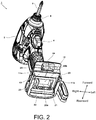
- Fig. 2 is a perspective view showing the shape of the battery pack mounting part 10 of the electric tool body 1.
- the electric tool body 1 shown here is an impact driver, and a handle part that extends downward form a body part of a housing 2 is provided and the battery pack mounting part 10 is formed below the handle part.
- a trigger switch 4 is provided in the handle part.
- An anvil (not shown) serving as an output shaft is provided on the front side of the housing 2, and the tip tool holding part 8 for mounting the tip tool 9 is provided at the tip of the anvil.
- a plus driver bit is mounted as the tip tool 9.
- the battery pack mounting part 10 corresponding to the shape of a battery pack to be mounted is formed not only in the electric tool, but also in all electric appliances using this battery pack, and a battery pack that is not compatible with the battery pack mounting part 10 cannot be mounted.
- rail grooves 11a and 11b that extend parallel to each other in the front to rear direction are formed in an inner wall part on both left and right sides, and a terminal part 20 is provided therebetween.
- the terminal part 20 is produced by integrally molding a non-conductive material such as a synthetic resin, and a plurality of metal terminals, for example a positive electrode input terminal 21, a negative electrode input terminal 22, an LD terminal (abnormal signal terminal) 23 are cast therein.
- a vertical surface 20a serving as an abutment surface in the mounting direction (the front to rear direction) and a horizontal surface 20b are formed.
- the horizontal surface 20b is a surface that is adjacent to and faces an upper step surface 115 (to be described below in Fig. 7 ) when the battery pack 100 is mounted.
- a curved part 12 in contact with a ridge part 132 (to be described below in Fig. 7 ) of the battery pack 100 is formed, and a protrusion part 24 is formed in the vicinity of the center of the curved part 12 to the left and right thereof.
- the protrusion part 24 serves as a screwing boss for a housing of the electric tool body 1 formed in two parts in the left to right direction and also serves as a stopper for restricting a relative movement of the battery pack 100 in the mounting direction.
- a width S1 of the protrusion part 24 in the left to right direction is a width corresponding to a stopper part 131 (to be described below in Fig. 7 ) formed on the side of the battery pack 100.
- Fig. 3 shows diagrams of another electric tool body 30A supporting 108 V
- Fig. 3(1) is a side view showing a state in which power is supplied from a power supply cord 90
- Fig. 3(2) is a bottom view of the battery pack mounting part 40
- Fig. 3(3) is a diagram showing the shapes of the power supply cord 90 and a connector part 93.
- a motor used is a brushless motor with specifications corresponding to an alternating current of 100 V, for example, a brushless DC motor driven by an inverter circuit (to be described below in Fig. 4 ).
- a direct current of 108 V output from the battery pack 100 is input to the inverter circuit, or a commercial power supply (AC power supply device) such as an alternating current of 100 V (60 Hz) is rectified by a rectification circuit to be described below and is then input to the inverter circuit.
- AC power supply device such as an alternating current of 100 V (60 Hz) is rectified by a rectification circuit to be described below and is then input to the inverter circuit.
- the power supply cord 90 mounted in the electric tool body 30A holds two terminals 92a and 92b on one side of a connection cord 94 and has a plug part 91 for mounting in an outlet of a commercial power supply, and the connector part 93 connected to the electric tool body 30A is formed on the other side.
- a part to which the connector part 93 is connected is disposed in the battery pack mounting part 40 after the battery pack 100 is removed. That is, when the power supply cord 90 is connected to the electric tool body 30A, it is necessary to remove the battery pack 100 from the electric tool body 30A, and on the other hand, when the battery pack 100 is mounted in the electric tool body 30A, it is necessary to remove the power supply cord 90.
- Fig. 3(2) is a diagram of the battery pack mounting part 40 of the electric tool body 30A when viewed from below, and is a diagram in a direction of an arrow A in Fig. 3(1) .
- This figure shows a state in which both the battery pack 100 and the power supply cord 90 are removed.
- the battery pack 100 is mounted so that the battery pack 100 slides from the rear side to the front side (from the right to the left in the drawing). Therefore, on a mounting surface 40a, an opening part is formed on the upstream side in the mounting direction, and two rail grooves (device side rails) 48a and 48b are formed on the lateral side.
- a recess part 40b formed to be recessed upwardly is formed on the side upstream (rear side part) from the opening part.
- a terminal part 41 connected to a positive electrode terminal and a negative electrode terminal of the battery pack 100 is provided in the vicinity of substantially the center of a part interposed between the rail grooves 48a and 48b of the mounting surface 40a.
- an AC socket 49 is provided slightly behind the terminal part 41. In the AC socket 49, in the circumferential direction, a first device side terminal 49a, a second device side terminal 49b, and a third device side terminal 49c, which have a pin shape, are formed.
- Fig. 3(3) is a diagram showing the shape of the connector part 93 of the power supply cord 90
- the left side diagram is a view of the connector part 93 when viewed from the outside in the longitudinal direction
- the right side diagram is a side view of the entire shape of the power supply cord 90 including the connector part 93.
- a male screw is formed on the outer circumferential surface of a connector body 93a, and a cylindrical fixing screw 93b is held in a state in which it is relatively rotatable on the outer circumferential side of the male screw, and an amount of movement in the axial direction is limited.
- the external form of the connector part 93 is a circle, and in the inner circumferential part, three female type terminals including a first cord side terminal 95a, a second cord side terminal 95b, and a third cord side terminal 95c are disposed side by side in the circumferential direction.
- a first cord side terminal 95a in order to supply commercial power, it is sufficient to connect only two of the first cord side terminal 95a and the second cord side terminal 95b, it is sufficient that the third device side terminal 49c connected to the third cord side terminal 95c be in a non-wiring state in the electric tool body 30A, and be used as a ground wire.
- the fixing screw 93b holds the power supply cord 90 so that it does not fall off from the electric tool body 30A, and a female screw part on the inner circumferential side of the fixing screw 93b is screwed into a male screw part 49d formed on the outer circumferential surface of the AC socket 49. In this manner, after the connector body 93a is inserted into the AC socket 49, the fixing screw 93b is tightened and screwed into a male screw on the side of the AC socket 49, and thus the power supply cord 90 can be fixed so that it does not fall off from the electric tool body 30A.
- the electric tool body 30A has been described as an example of the electric appliance body, a configuration in which the power supply cord 90 is connected to a part that is not exposed to the outside when the battery pack is mounted in the battery pack mounting part 40 can be used for any electric appliance body which has the battery pack mounting part 40 and in which the battery packs 1 and 30 can be mounted.
- the power supply cord 90 corresponds to an AC power supply device of the present invention.
- a method of fixing the power supply cord 90 and the electric tool body 30A is not limited to a screw method, and a power supply cord that is held by a fitting pressure of a terminal part may be used and a power supply cord using other known fixing or holding methods may be used.
- Fig. 4 is a block diagram showing the configuration of the drive control system of the motor 35.
- a direct current supplied from the battery pack 100 is used to generate an exciting current using an inverter circuit 70, flows through a predetermined coil of the motor 35 while switching an exciting current, and thereby a brushless type motor 35 rotates.
- An input from the battery pack 100 is input through a positive electrode input terminal 81 connected to a positive electrode terminal 161 of the battery pack 100 and a negative electrode input terminal 82 connected to a negative electrode terminal 162 of the battery pack 100.
- the motor 35 can be, for example, an inner rotor type, and includes a rotor 35a including a permanent magnet (magnet) having a plurality of sets (2 sets in the present example) of N pole and S pole, a stator 35b including 3-phase stator windings U, V, and W in a star connection, and three rotating position detecting elements (Hall elements) 65 that are disposed at predetermined intervals in the circumferential direction, for example, every 60°, in order to detect a rotation position of the rotor 35a.
- a rotation position detection circuit 53 Such an output is converted into a pulse train by a rotation position detection circuit 53 and is output to a calculation portion 51.
- a rotational speed detection circuit 54 detects a rotational speed of the motor 35 using an output of the rotation position detection circuit 53 and outputs it to the calculation portion 51.
- a direction and time for supplying a current to the stator windings U, V, and W are determined using such an output.
- a control signal output circuit 52 generates a drive signal for switching predetermined switching elements Q1 to Q6 according to an instruction from the calculation portion 51 based on output signals of an applied voltage setting circuit 58 and the rotation position detection circuit 53, and outputs the drive signal to the inverter circuit 70.
- the inverter circuit 70 includes six switching elements Q1 to Q6 such as IGBTs connected as a 3-phase bridge type. Respective gates of the switching elements Q1 to Q6 are connected to the control signal output circuit 52, and respective emitters or respective collectors are connected to the stator windings U, V, and W in a star connection.
- the six switching elements Q1 to Q6 perform a switching operation by switching element drive signals (drive signals such as H1 to H6) input from the control signal output circuit 52, and direct current voltages of the battery pack 100 applied to the inverter circuit 70 are applied as 3-phase (a U-phase, a V-phase, and a W-phase) voltages Vu, Vv, and Vw to the stator windings U, V, and W.
- switching element drive signals drive signals such as H1 to H6
- direct current voltages of the battery pack 100 applied to the inverter circuit 70 are applied as 3-phase (a U-phase, a V-phase, and a W-phase) voltages Vu, Vv, and Vw to the stator windings U, V, and W.
- the calculation portion 51 sets whether or not to operate a trigger 34A for operating an operation switch 56 (or the operation switches 4 and 34 in Fig. 1 ) by a switching operation detection circuit 57, changes a pulse width (duty ratio) of a PWM signal based on a signal from the applied voltage setting circuit 58 which varies according to the magnitude of an operation amount (stroke), and drives respective gates of the six switching elements Q1 to Q6 through the control signal output circuit 52.
- the drive control an amount of power supplied to the motor 35 is adjusted, and start/stop and a rotational speed of the motor 35 are controlled.
- the PWM signal is supplied to any of the positive power supply side switching elements Q1 to Q3 or the negative power supply side switching elements Q4 to Q6 of the inverter circuit 70, and when the switching elements Q1 to Q3 or the switching elements Q4 to Q6 are switched at a high speed, an amount of power supplied to the stator windings U, V, and W from a direct current voltage of the battery pack 100 is controlled.
- the calculation portion 51 includes a microcomputer for outputting a drive signal based on processing programs and data.
- the calculation portion 51 includes a ROM for storing processing programs and control data, a RAM for temporarily storing data, a timer, and the like.
- a voltage between both ends of a condenser 61 is detected as a voltage of an input power supply by a voltage detection circuit 59, and is output to the calculation portion 51.
- a power supply of the electric tool body 30A can be supplied using not only the battery pack 100 but also the power supply cord 90, and the first device side terminal 49a and the second device side terminal 49b of the AC socket 49 for an AC input provided in the electric tool body 30A are connected to an input side of a diode bridge 60.
- the diode bridge 60 is a rectification circuit that allows a current to flow to only one side by performing full-wave rectification using four diodes for rectification, and converts an alternating current voltage into a direct current voltage.
- An output of the diode bridge 60 is connected to the inverter circuit 70.
- a smoothing circuit may be interposed between the diode bridge 60 and the inverter circuit 70.
- a magnitude of a current flowing through the inverter circuit 70 is measured by a current detection circuit 55 using a shunt resistor 62, a value thereof is fed-back to the calculation portion 51, and adjusted so that set driving power is applied to the motor 35.
- Fig. 5 is a diagram for explaining a state in which the power supply cord 90 is connected to an electric tool body
- Fig. 5(1) is an example of connection to the electric tool body 30A
- Figs. 5(2) and 5(3) are diagrams showing an example of connection to electric tool bodies 30B and 30C according to a modified example thereof.
- the electric tool bodies 30B and 30C are different only in a connection position and a connection method for the power supply cord 90 from the electric tool body 30A shown in Fig. 3 , and other configurations not related to connection to the power supply cord 90 are the same as those of the electric tool body 30A. Therefore, the voltage switching type battery pack 100 shown in Fig. 1 can be mounted in any of the electric tool bodies 30A to 30C.
- a fixed voltage type 108 V battery pack and battery packs 200 and 300 to be described in the following Examples 2 and 3 can be attached to the electric tool bodies 30A to 30C.
- the power supply cord 90 may have a length sufficient for an operator to perform an operation while he or she grips the handle part 33 of the electric tool body 30A with one hand. In a temporary operation at a location that the length of the power supply cord 90 does not reach, when the power supply cord 90 is removed and the battery pack 100 is mounted, the same operation can be performed without concern regarding a decrease in the output of the electric tool body 30A.
- a method of connecting the power supply cord 90 to the electric tool body 30A in the form shown in Fig. 5(1) has an advantage in that the weight of the electric tool body 30A is reduced because the battery pack 100 is always removed during an operation with an AC power supply.
- Fig. 5(2) shows the electric tool body 30B according to a modified example of the electric tool body 30A in Fig. 5(1) .
- the position of the AC socket 49A is formed on the lower surface of a housing of the electric tool body 30B and at a point on the front side relative to the battery pack 100.
- a bottom view of the AC socket 49A is shown.
- the shape of the AC socket 49A is completely the same as the AC socket 49 shown in Fig. 3(2)
- the third device side terminal 49c is provided in addition to the first device side terminal 49a and the second device side terminal 49b connected for supplying commercial power.
- the power supply cord 90 can be connected while the battery pack 100 is mounted.
- any cap or cover that blocks an opening of the AC socket 49A may be provided in order to prevent the AC socket 49A from being exposed to the outside.
- an output voltage of the battery pack 100 is 108 V in a direct current connection, and a commercial AC power is an alternating current of 100 V to 120 V, the electric tool body 30B can be driven using both inputs arbitrarily.
- the power supply cord 90 corresponds to an AC power supply device of the present invention.
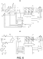
- Fig. 6(1) is a circuit block diagram of a drive control system of the electric tool body 30B shown in Fig. 5(2) .
- this circuit is the same as the circuit shown in Fig. 4 , but a semiconductor switching element 66 such as an insulated gate bipolar transistor (IGBT) is inserted midway along a positive electrode side input line from the battery pack 100.
- a gate signal of the switching element 66 is connected to a control signal line 66a from the calculation portion 51, and the calculation portion 51 controls connection or disconnection between source and drain terminals of the switching element 66.
- IGBT insulated gate bipolar transistor
- a battery voltage detection circuit 67 that monitors a voltage of the battery pack 100 and a commercial power supply detection circuit 68 that monitors whether an AC voltage (or a voltage) is applied are provided, and outputs thereof are input to the calculation portion 51.
- the calculation portion 51 turns a gate signal of the switching element 66 off, and disconnects an input circuit from the battery pack 100.
- the calculation portion 51 turns a gate signal of the switching element 66 on, and connects an input circuit from the battery pack 100.
- connection between the diode bridge 60 and the inverter circuit 70 may be disconnected by a switching operation of the relay member, and an output of the battery pack 100 may be connected to the inverter circuit 70.
- a configuration in which an indicating member indicating which power is operated for the electric tool 30B during use, for example, an LED, is displayed during driving by commercial AC power may be used.
- Fig. 5 will be referred to again.
- Fig. 5(3) shows the electric tool body 30C according to another modified example of the present example.
- the electric tool body 30C is the same as those shown in Figs. 5(1) and 5(2) in that it can be driven by the battery pack 100 with a direct current of 108 V and driven by AC power supply via the power supply cord 90, but the power supply cord 90 is connected via the connection adapter 75.
- the connection adapter 75 is a so-called dummy case for connecting two output lines from the power supply cord 90 to the positive electrode input terminal 81 and the negative electrode input terminal 82 for the battery pack 100.
- connection adapter 75 and particularly, the upper half shape (upper case), is configured to be compatible with the battery pack 100, but no battery cell is housed therein.
- the lower case of the connection adapter 75 may have any shape, but the shape of the case of the connection adapter 75 with an upper case and a lower case may be the same as that of the battery pack 100.
- a rectification circuit using the diode bridge 60 is included in the electric tool bodies 30A to 30C, there is no need to include a rectification circuit in the connection adapter 75.
- it does not exclude disposition of an auxiliary electrical circuit for assisting an operation of an electrical circuit included in the electric tool bodies 30A to 30C in the connection adapter 75.
- connection adapter 75 rails (adapter side rails, not shown) are formed on both left and right sides of the upper step surface, and adapter side rails are engaged with a rail groove (its shape is the same as those of the rail grooves 48a and 48b shown in Fig. 3(2) ) formed on the side of the electric appliance body 30B.
- the same latch mechanism as in the battery pack 100 is provided in the connection adapter 75, and a latch button 78 for operating it is provided.
- a plurality of slots are formed, and in a part accessible from two slots among them, only two of a positive electrode terminal and a negative electrode terminal are formed (to be described below in Fig. 6(2) ).
- An AC socket 79 having the same shape as the AC socket 49 shown in Fig. 3(2) is provided on the lower surface of the case of the connection adapter 75.
- a bottom view of the AC socket 79 provided on the lower surface of the connection adapter 75 is shown.
- the shape of the AC socket 79 is completely the same as that of the AC socket 49 shown in Fig. 3(2)
- a third adapter side terminal 79c is provided in addition to a first adapter side terminal 79a and a second adapter side terminal 79b connected for supplying commercial power.
- the third adapter side terminal 79c is wired in the connection adapter 75 and connected to any terminal on the side of the electric tool body or not wired.
- the first adapter side terminal 79a of the AC socket 79 is connected to the positive electrode input terminal 81 (refer to Fig. 4 ) on the side of the electric tool 30 through an adapter side positive electrode terminal 77a using a power line 76a wired in the connection adapter 75.
- the second adapter side terminal 79b is connected to the negative electrode input terminal 82 (refer to Fig. 4 ) on the side of the electric tool 30 through an adapter side negative electrode terminal 77b using a power line 76b wired in the connection adapter 75.
- Fig. 4 the first adapter side terminal 79a of the AC socket 79 is connected to the positive electrode input terminal 81 (refer to Fig. 4 ) on the side of the electric tool 30 through an adapter side positive electrode terminal 77a using a power line 76a wired in the connection adapter 75.
- the power supply cord 90 and the connection adapter 75 correspond to an AC power supply device of the present invention.
- the power supply cord 90 is configured to be detachable using the AC socket 79 and the connector part 93 on a lower surface of the connection adapter 75.
- a configuration in which the connection adapter 75 and a connection cord 44 are directly connected, and the connection cord 44 extends directly from the case of the connection adapter 75 may also be used.
- any cap or cover that blocks an opening of the AC socket 79 may be provided in order to prevent the AC socket 79 from being exposed to the outside.
- Fig. 6(2) is a circuit block diagram of a drive control system of the electric tool body 30C shown in Fig. 5(3) .
- this circuit is the same as the circuit shown in Fig. 4 , but it is wired so that the positive electrode terminal 161 and the negative electrode terminal 162 of the battery pack 100 are mounted in the input terminals 81 and 82 of the diode bridge 60.
- the battery pack 100 Since the battery pack 100 has a direct current of 108 V, there is no problem when it is connected to the inverter circuit 70 via the diode bridge 60.
- the connection adapter 75 Even if the connection adapter 75 is mounted, the adapter side positive electrode terminal (first terminal) 77a formed in the connection adapter 75 is connected to the positive electrode input terminal 81, and the adapter side negative electrode terminal (second terminal) 77b is mounted in the negative electrode input terminal 82, since an alternating current is rectified by the diode bridge 60, the motor 35 can be driven by operating the inverter circuit 70 in the same manner.
- connection adapter 75 Since no battery cell is included in the connection adapter 75, it is not necessary to provide a connection terminal for signal transmission other than the adapter side positive electrode terminal 77a and the adapter side negative electrode terminal 77b. However, one of the connection terminals may be used in order to notify the electric tool body 30C of the fact that the connection adapter 75 is connected.
- a brushless DC motor is driven using a direct current input with a direct current of 108 V and the inverter circuit 70.
- the type of the motor used is not limited to the brushless motor, and other motors that are driven at about AC 100 to 120 V, for example, an alternating current commutator motor, may be used. In such a configuration, an electric tool using an alternating current commutator motor can be driven in the battery pack 100, and an AC/DC compatible electric tool can be easily realized.
- Fig. 7 is a perspective view showing the external form of the battery pack 100.
- the frame of the battery pack 100 is formed of a lower case 101 and an upper case 110 which are divided in the vertical direction, and the lower case 101 and the upper case 110 are fixed by four screws (not shown).
- a mounting part in which two rails 138a and 138b are formed is formed for attachment to the battery pack mounting part 40.
- the rails 138a and 138b on the side of the battery pack are formed in a direction parallel to the mounting direction of the battery pack 100 and parallel to left and right side surfaces of the upper case 110.
- the rails 138a and 138b are formed to correspond to the rail grooves 48a and 48b (refer to Fig. 3(2) ) formed in the battery pack mounting part 40 of the electric tool body 30, and while the rails 138a and 138b are fitted to the rail grooves 48a and 48b, when the latch mechanism operates, the battery pack 100 is fixed to the electric tool body 30.
- a flat lower step surface 111 is formed on the front side of the upper case 110, and the upper step surface 115 formed to be higher than the lower step surface 111 is formed in the vicinity of the center.
- a part connecting the lower step surface 111 and the upper step surface 115 becomes a step part 112 formed in a step shape, and a front side area from the step part 112 to the upper step surface 115 becomes a slot group disposition area 120 (refer to Fig. 7(2) ).
- a slot group disposition area 120 a plurality of slots (121 to 124) that extend to the rear side from the front step part 112 are formed.
- the positive electrode terminal insertion port 121 is disposed on the side close to the left side rail 138b
- the negative electrode terminal insertion port 122 is formed on the side close to the right side rail 138a.
- a low voltage switching member insertion port 123 and a high voltage switching member insertion port 124 are formed in a part interposed between the positive electrode terminal insertion port 121 and the negative electrode terminal insertion port 122. Inside the positive electrode terminal insertion port 121 and the negative electrode terminal insertion port 122, a positive electrode terminal and a negative electrode terminal, which are invisible and made of a metal, are disposed. In addition, a voltage switching member (to be described below) is disposed in a part in which positions of the low voltage switching member insertion port 123 and the high voltage switching member insertion port 124 overlap (the internal space of the upper case 110). In addition, in Fig.
- the slot group disposition area 120 serves as a terminal disposition area.
- the ridge part 132 formed to be raised is formed on the rear side of the upper step surface 115.
- the ridge part 132 has an external form that is raised above the upper step surface 115 and the recessed stopper part 131 is formed in the vicinity of the center thereof. Since the stopper part 131 serves as a housing and an abutment surface when the battery pack 100 is mounted in the protrusion part 24 (refer to Fig. 2 ) of the battery pack mounting part 10, when the protrusion part 24 on the side of the electric tool body 1 is inserted until it abuts the stopper part 131, a plurality of terminals 21 to 23 (refer to Fig.
- a slit 134 serving as a cooling air inlet connected to the inside of the battery pack 100 is provided inside the stopper part 131.
- a locking part of a latch 141 of the battery pack 100 projects vertically outward from a lower part of the rails 138a and 138b due to an action of a spring, and is engaged with a recess (not shown) formed in the rail grooves 48a and 48b of the electric tool body 30, and thereby it is prevented the battery pack 100 from falling off.
- the slit 134 is covered so that it is invisible from the outside.
- the slit 134 is an air window used to forcibly flow cooling air inside the battery pack 100 when the battery pack 100 is connected to a charger (not shown) for charging, and when mounted in the electric tool body 30, the slit 134 serving as a cooling air inlet is in a closed state.
- a switching protrusion 24A for switching an output of the battery pack 100 to the low voltage side is additionally formed.
- the switching protrusion 24A is a switching element integrally formed with a base part of the terminal part 20A and is made of a synthetic resin. Since the switching protrusion 24A itself is simply used to move a rotary type terminal base 171 (refer to Fig. 9 ), and is not used as a terminal that transmits power or a signal, it is not necessary to form it using a conductive material, and it may be integrally formed using the same insulating material as that of the base part of the terminal part.
- Fig. 7(2) shows a state when mounted in a terminal part 80 on the side of the electric tool body 30 driven at 108 V.
- the terminal part 80 is formed when the positive electrode input terminal 81 and the negative electrode input terminal 82 which are made of a metal are fixed at a base part made of a synthetic resin.
- a switching protrusion 84 for switching an output of the battery pack 100 to the high voltage side is additionally formed.
- the switching protrusion 84 is a member integrally formed with a base part of the terminal part 80 and is made of a synthetic resin.
- the external form of the battery pack 100 is the same when it has an output of 36 V or an output of 108 V.
- an output voltage optimal for an electric appliance body in which the battery pack 100 is mounted by the switching protrusion 24A or the switching protrusion 84 is selected (switched).
- Fig. 8 shows perspective views of the appearance of the cell pack 150 which is housed in the battery pack 100 and in which a plurality of cells 151 are stacked to obtain one pack.
- Fig. 8(1) is a perspective view
- Fig. 8(2) is a side view when viewed in the axial direction of the cell 151.
- a total of 30 cells 151 called a 14500 size of a secondary battery that can be charged and discharged a plurality of times and having a diameter of 14 mm and a length of 50 mm are stacked.
- Ten cells 151 are used as one unit, and three cell units 156 to 158 are formed.
- the cells 151 are stacked so that respective axes A1 are parallel to one another, and disposed so that directions of adjacent cells 151 are alternately reversed, and positive electrode terminals and negative electrode terminals of adjacent cells 151 are connected by a metal thin plate 159 to form 10 serial connections.
- the outermost cylindrical part of the stacked cells 151 is covered with a separator 152 which serves as an insulator and is made of a synthetic resin, and thus the cells 151 are held so that they do not move relative to the separator 152.
- the length in the axial direction is 50 mm
- the length in the width direction orthogonal to the axial direction is 124.8 mm
- the length in the height direction orthogonal to the axial direction is 57.3 mm.
- a unit weight of the cells 151 is about 23 g
- a total weight of the cells 151 is 690 g.
- a volume of a part occupied by the cells 151 is 230,907 mm 3
- a volume occupied by the separator 152 is 67,392 mm 3
- a total volume is 298,299 mm 3 .
- a total weight of the battery pack 100 can be reduced to less than 800 g or 2 1b (pounds).
- the 18650 size has a diameter of 18 mm and a length of 65 mm, has a volume that is slightly larger than twice the 14500 size, and has a weight of 46 g that is twice that of the 14500 size cell. If 30 cells of 18650 size are stacked in order to obtain a direct current of 108 V, since the weight of only the cells is 1380 g, and the weight of the battery pack itself becomes heavy, its size and weight become impractical for an electric tool by which an operator performs an operation while gripping it with one hand.
- an upper limit at which an operator can perform an operation comfortably with one hand is 2 kg or 5 1b in total weight of an electric tool after a battery pack is mounted. Therefore, when 30 cells of 18650 size are used to obtain an output of 108 V, it is difficult to realize a portable electric tool that can be operated with one hand.
- 14500 size lithium ion batteries with the same size as a so called AA-size battery are stacked, it is possible to realize an electric tool having a high voltage while maintaining portability.
- the battery pack 100 of the present example it is possible to reliably secure an output voltage of 100 V or more corresponding to that of an AC power supply, and the cell weight of the cell pack 150 can be reduced to 0.69 kg.
- 18650 size battery cells or other size battery cells may be used to obtain a battery pack.
- Fig. 9(1) is a diagram showing a state when the battery pack 100 is mounted in an electric tool body or electric appliance body with a rated voltage of 36 V.
- the battery pack 100 includes a voltage switching mechanism 170 for switching whether outputs of the cell units 156 to 158 are connected in parallel or connected in series.
- the voltage switching mechanism 170 which is a voltage switching element for switching output voltage of the battery pack 100 includes the rotary type terminal base 171 supported by a swing shaft 172 fixed on a substrate 160, and is provided in a terminal disposition area in which a connection terminal for power supply is disposed in the mounting direction of the battery pack 100.
- the rotary type terminal base 171 is a member for short circuiting or opening a plurality of contact points positioned on the inner circumferential side of the connection terminals 173a to 173d and contact points positioned on the outer circumferential side thereof by installing a plurality of square bar-like connection terminals 173a to 173d in a member that extends from the swing shaft 172 in two directions.
- the rotary type terminal base 171 is made of a synthetic resin, and is formed by casting each two connection terminals 173a to 173d made of a metal on one side and the other side of the swing shaft 172 with a gap.
- the connection terminals 173a and 173b are disposed on the side close to the negative electrode terminal 162 so that one surface facing the substrate 160 is exposed.
- the connection terminals 173c and 173d are disposed on the side close to the positive electrode terminal 161 so that one surface facing the substrate 160 is exposed.
- the substrate 160 is use to fix the positive electrode terminal 161 and the negative electrode terminal 162, and dispose a plurality of electrodes (contact points) 176a to 176j that are used to establish or change an electrical connection path from these terminals to the cell units 156 to 158.
- the plurality of contact points 176a to 176j are provided in an area that partially overlaps a rotating area of the rotary type terminal base 171 in an upper part of the substrate 160.
- the switching protrusion 24A is formed in the terminal part 20A.
- the switching protrusion 24A functions as a switching element for switching output voltage or a connection element and is inserted into the third slot 123 or 124 which is positioned between the first slot 121 into which a positive electrode input terminal is inserted and the second slot 122 into which a negative electrode input terminal is inserted.
- the switching protrusion 24A pushes the rotary type terminal base 171 at a position of an arrow 25, the rotary type terminal base 171 rotates counterclockwise in a top view and is positioned at a first position shown in Fig. 9(1) .
- connection terminal 173a short-circuits the electrodes (contact points) 176d and 176b
- connection terminal 173b short-circuits the electrodes (contact points) 176e and 176c
- connection terminal 173c short-circuits the contact points 176i and 176g
- connection terminal 173d short-circuits the contact points 176j and 176h.
- the voltage switching mechanism 170 which is a voltage switching element is disposed at substantially the same height as positions at which the positive electrode terminal 161 and the negative electrode terminal 162 are disposed. Therefore, there is no need to change a positional relationship of steps from the lower step surface 111 to the upper step surface 115 of the battery pack 100.
- Fig. 9(2) shows connection in a state at a position at which the rotary type terminal base 171 rotates counterclockwise in a top view by the switching protrusion 24A as shown in Fig. 9(1) , that is, at a first position.
- the + side output of the cell unit 156 is directly connected to the positive electrode terminal 161.
- the + side output of the cell unit 157 is connected to the contact point 176b, and the + side output of the cell unit 158 is connected to the contact point 176g.
- the - side output of the cell unit 156 is connected to the contact point 176e
- the - side output of the cell unit 157 is connected to the contact point 176j
- the - side output of the cell unit 158 is directly connected to the negative electrode terminal 162.
- the contact points 176d and 176b, the contact points 176e and 176c, the contact points 176i and 176g, and the contact points 176j and 176h are in a connection state.
- the cell units 156 to 158 are in a parallel connection state, and a direct current with a rated voltage of 36 V is output between the positive electrode terminal 161 and the negative electrode terminal 162.
- the switching protrusion 24A is engaged with the rotary type terminal base 171 during mounting and moved to the first position.
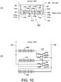
- Fig. 10(1) is a diagram showing a state when the battery pack 100 is mounted in an electric tool body or electric appliance body with a rated voltage of 108 V.
- the switching protrusion 84 is formed in the terminal part 80, and no protrusion is formed at a position of the switching protrusion 24A of the terminal part 20 of a 36 V device.
- the switching protrusion 84 functions as a switching element for switching output voltage or a connection element, and is inserted into the third slot 124 which is positioned between the first slot 121 into which a positive electrode input terminal is inserted and the second slot 122 into which a negative electrode input terminal is inserted.
- the contact points 176d and 176a, the contact points 176e and 176b, the contact points 176i and 176f, and the contact points 176j and 176g are in a connection state.
- the cell units 156 to 158 are in a serial connection state, and a direct current with a rated voltage of 108 V is output from the positive electrode terminal 161 and the negative electrode terminal 162.
- a configuration in which a click mechanism or a latch mechanism is provided on the swing shaft 172 of the rotary type terminal base 171 as a swing member, and no swing occurs if the switching protrusion 24A or the switching protrusion 84 does not apply a predetermined rotation torque or more to the swing member by may be used.
- the contact points 176a and 176f are points of electrodes that are not connected to any part, these are removed, and electrode gaps between the contact points 176b and 176c, and the contact points 176g and 176h increase, and thereby a risk of short-circuiting between adjacent electrodes during switching may be reduced.
- a high voltage corresponding to that of a commercial power supply driven electric tool can be obtained from the battery pack 100, and a high output portable electric tool or electric appliance can be realized.
- a voltage switching element (the voltage switching mechanism 170) for switching between a parallel connection and a serial connection is disposed inside the battery pack 100, and switches between connections of the cell units 156 to 158.
- the voltage switching mechanism 170 functioning as a voltage switching element is disposed at a position with substantially the same height as positions at which the positive electrode terminal 161 and the negative electrode terminal 162 functioning as power supply terminals are disposed.
- the size of the battery pack 100 in the vertical direction can be made compact.
- Fig. 11 is a perspective view showing the shapes of the battery pack 200 and a terminal part connected thereto
- Fig. 11(1) shows a state when connected to an electric appliance with a rated voltage of 36 V
- Fig. 11(2) shows a state when connected to an electric appliance with a rated voltage of 108 V.
- the external form of the battery pack 200 is basically the same as the shape of the battery pack 100 of the first example shown in Fig. 1 to Fig. 8 except a part (a shape near a disposition area of a slot group).
- the battery pack 200 in a housing formed by bonding a lower case 201 and an upper case 210, 30 cells 151 of 14500 size lithium ion batteries are housed in the same manner as shown in Fig. 8 . If the housing is allowed to be large, 18650 size cells may be used, or cells with other shapes and sizes may be used.
- the upper case 210 of the battery pack 200 an attachment mechanism for mounting on the side of the electric tool body 1 or the electric tool body 30 is formed, but its configuration and shape are almost the same as those of the battery pack 100 of the first example shown in Fig. 7 .
- a lower step surface 211 for guiding a terminal part on the side of the electric appliance and an upper step surface 215 disposed thereabove are formed, and a plurality of terminal insertion ports (slots) are formed at a step part 212 serving as a boundary between the lower step surface 211 and the upper step surface 215.
- a step part 212 serving as a boundary between the lower step surface 211 and the upper step surface 215.
- rail parts 238a and 238b fitted into electric appliance body side groove rail grooves are formed.
- five terminal insertion ports are shown in the left to right direction, the number of terminal insertion ports disposed is arbitrary, and may be further increased.
- a ridge part 240 is formed above the upper step surface 215, and latch parts 241 are provided on both left and right sides of the ridge part 240.
- the latch part 241 is interlinked with a latch claw 241a. While a stopper part and a slit as a cooling air inlet are formed in the ridge part 240, since its shape is the same as that of the first example shown in Fig. 7 , description thereof is omitted here.
- Fig. 11(1) shows a state when connected to an electric appliance body or electric tool body 1 with a rated voltage of 36 V, or the like.
- a terminal part 270 provided on the side of an electric appliance body 1 has a narrow width in the left to right direction, and the battery pack 200 is moved so that a positive electrode input terminal 271 and a negative electrode input terminal 272 are inserted into two terminal insertion ports 222 and 224 closer to the center.
- Fig. 11(2) shows a state when connected to an electric appliance body, or electric tool body 30 with a rated voltage of 108 V or the like.
- the terminal part 280 of the electric tool body 30 has a wide width in the left to right direction with respect to the terminal part 270, and an area between them becomes a terminal disposition area.
- a positive electrode input terminal 281 and a negative electrode input terminal 282 disposed closer to both left and right ends are provided, and a connection element 283 is formed substantially at the center in the left to right direction.
- the length of the connection element 283 in the longitudinal direction is substantially the same (strictly slightly shorter than) as that of the positive electrode input terminal 281 and the negative electrode input terminal 282.
- the size in the height direction is the same. This is because, when the connection element 283 for operating a voltage switching element is added, it is not necessary to change a dimensional relationship between the positive electrode input terminal 281 and the negative electrode input terminal 282, and thus it is possible to avoid an increase in the size of the battery pack 200 due to addition of the voltage switching element.
- Fig. 12 is a connection circuit diagram of the battery pack 200.
- Three cell units 156 to 158 (refer to Fig. 8(2) ) are housed in the battery pack 200.
- the cell units 156 to 158 are formed as the cell pack 150 shown in Fig. 8 , and held by the separator 152, and each includes 10 cells 151 of 14500 size lithium ion batteries connected in series.
- a total of 10 cells are shown as one battery in Fig. 12 .
- the terminal insertion ports (slots) 221 to 225 into which input terminals on the side of the terminal parts 270 and 280 are inserted one to four connection terminals are disposed side by side in an inserting direction of the terminal parts 270 and 280.
- connection terminal group disposed here serves as a voltage switching element that switches between a parallel connection and a serial connection of the battery pack 200.
- a group of the terminal insertion port 222 and the terminal insertion port 224 corresponds to the terminal part 270 for 36 V, and a switching terminal group (a terminal group 232 and a terminal group 234) for outputting a low voltage is disposed there.
- the positive electrode input terminal 271 is mounted in contact with three terminals of the terminal group 232, and the negative electrode input terminal 272 is mounted in contact with three terminals of the terminal group 234.
- a group of the terminal insertion port 221 and the terminal insertion port 225 corresponds to the terminal part 280 for 108 V, and a switching terminal (a terminal 231 and a terminal group 235) for outputting a high voltage is disposed there.
- the positive electrode input terminal 281 is mounted in contact with the terminal 231, and the negative electrode input terminal 282 is mounted in contact with the terminal 235.
- the connection element 283 for switching output voltage is additionally provided at the center parts of the terminal part 280 to the left and right thereof.
- the connection element 283 serving as a voltage switching element that switches between a parallel connection and a serial connection is inserted into the terminal insertion port 223.
- the connection element 283 has a conducting part 283a on the tip side (in the drawing, side close to the battery pack 200) and a conducting part 283c on the rear end side, and when an insulator 283b is disposed between the conducting parts 283a and 283c, the conducting part 283a and the conducting part 283c are in an electrically non-conductive state.
- the object of the conducting parts 283a and 283c is to function as a short-circuiting component that causes predetermined terminals in a terminal group 233 to be short-circuited, and there is no need to provide a wiring from the conducting parts 283a and 283c on the side of the electric appliance body.
- connection element 283 may be produced by casting a metal plate forming the conducting parts 283a and 283c in a non-conductive connection element base formed by integral molding with the terminal part 280 or produced by attaching a metal plate to the outer circumferential surface of a non-conductive connection element base or performing a conducting treatment on the outer circumferential surface according to metal plating or the like. In this manner, in the terminal part 280, a short-circuiting component that connects a plurality of cell units in series is added and formed.
- Fig. 13 shows diagrams of the shapes of the terminals 231 to 235
- Fig. 13(1) is a top view
- Fig. 13(2) is a side view of the terminal group 232 (a diagram in a direction of an arrow B in Fig. 13(1) ).
- the terminals 231 and 235, and the terminals 232a, 233a, and 234a have the same shape as terminals that are widely used in the related art, and a flat plate is bent in a U-shape, both side surfaces in the vicinity of an opening end are recessed inward in a convex shape, and the narrowest part according to the convex part is formed in contact with both surfaces of a plate-like terminal on the side of the terminal part.
- the terminals 231, 235, 232a, 233a, and 234a have a shape of which the rear side is closed because a metal terminal on the side of a terminal part to be fitted does not penetrate through the rear side.
- the other terminal groups that is, the terminals 232b, 232c, 233b to 233d, 234b, and 234c, are fitted while a metal terminal on the side of a contacting terminal part is penetrated from the front to the rear, an opening is formed not only on the front side but also on the rear side.
- a connection state of the cell units 156 to 158 in the battery pack 200 can be set to either a parallel connection or a serial state using the electrode plate of the terminal part.
- Fig. 14 shows diagrams of states when the battery pack 200 is mounted in the terminal parts 270 and 280
- Fig. 14(1) shows a state of an output voltage of 36 V
- Fig. 14(2) shows a state when 108 V is output.
- the terminal part 270 when 36 V is output shown in Fig. 14(1) includes the positive electrode input terminal 271 and the negative electrode input terminal 272.
- the positive electrode input terminal 271 comes in contact with the terminals 232a, 232b, and 232c, and thus they are conductive.
- the terminal 232a is connected to the + terminal (positive electrode) of the cell unit 156
- the terminal 232b is connected to the + terminal of the cell unit 157
- the terminal 232c is connected to the + terminal of the cell unit 158.
- the positive electrode input terminal 271 is connected to the + terminals of the three cell units 156 to 158.
- the negative electrode input terminal 272 comes in contact with the terminals 234a, 234b, and 234c, and thus they are conductive.
- the terminal 234a is connected to the - terminal (negative electrode) of the cell unit 156
- the terminal 234b is connected to the - terminal of the cell unit 157
- the terminal 234c is connected to the - terminal of the cell unit 158. Therefore, the negative electrode input terminal 272 is connected to the - terminals of the three cell units 156 to 158.
- the terminals 233a to 233d are opened.
- the cell units 156 to 158 are connected in parallel, that is, a direct current with a rated voltage of 36 V is output to the positive electrode input terminal 271 and the negative electrode input terminal 272.
- Fig. 14(2) is a diagram showing a state in which the battery pack 200 is mounted in the terminal part 280.
- the terminal part 280 when 108 V is output includes the positive electrode input terminal 281, the negative electrode input terminal 282, and the connection element 283.
- the positive electrode input terminal 281 comes in contact with only the terminal 231 connected to the + terminal of the cell unit 156.
- the negative electrode input terminal 282 comes in contact with only the terminal 235 connected to the - terminal of the cell unit 158.
- the connection element 283 (connection terminal) is inserted in contact with four terminal groups (serial terminal elements 233a to 233d).
- connection element 283 the terminal 233a and the terminal 233b are short-circuited due to the conducting part 283a (refer to Fig. 12 ), and the terminal 233c and the terminal 233d are short-circuited due to the conducting part 283c (refer to Fig. 12 ).
- a gap between the terminal 233b and the terminal 233c remains in a non-conductive state due to the insulator 283b (refer to Fig. 12 ) formed in the connection element 283. Since the terminal 233a is connected to the - terminal of the cell unit 156, and the terminal 233b is connected to the + terminal of the cell unit 157, a serial connection state between the cell units 156 and 157 is established.
- a switching terminal group is configured by disposing terminals extending from the plurality of cell units adjacently, and thus the battery pack 200 that can support a plurality of power supplies is realized.
- serial terminal groups the serial terminal elements 233a to 233d
- the battery pack 200 that can be switched between 36 V and 108 V us realized.
- the third slot (223) into which a switching element (the connection element 283) for switching output voltage is inserted is provided separately from the slot (221 or 222) into which a positive electrode input terminal is inserted and slots (224 and 225) into which a negative electrode input terminal is inserted. Therefore, an output voltage from the side of the battery pack 200 is automatically switched simply by mounting the battery pack 200. Therefore, there is no need for the operator to be careful about an operation of switching battery voltages, and there is no risk of the side of the electric appliance body being damaged due to a set voltage error.
- the battery pack 200 when the battery pack 200 is removed, since the three cell units 156 to 157 are opened (in a non-connection state), an optimal state during storage and transportation can be brought into.
- the terminal group 232, the terminal group 234, and the connection element 283 functioning as voltage switching elements, and the terminal 231, the terminal 235, the terminal group 232, and the terminal group 234 functioning as power supply terminals are disposed at positions with substantially the same height in the vertical direction. Therefore, the size of the battery pack 200 in the vertical direction can be made compact.
- the structure of the battery pack 200 used in the second example can be effectively applied to not only a voltage switching type battery pack but also a fixed voltage type battery pack.
- the structure of such a battery pack is show in Fig. 15.
- Fig. 15 shows diagrams for explaining a circuit diagram of a 108 V dedicated battery pack 200A.
- this structure is the same as the structure in which the terminal groups 232 and 234 in Fig. 14(2) are removed, and the terminal insertion ports 222 and 224 (refer to Fig. 11 for both) formed at insertion positions of the terminal groups 232 and 234 are closed.
- the electric device body for 108 V uses the terminal part 280 including the positive electrode input terminal 281, the negative electrode input terminal 282, and the connection element 283.
- the structure of the terminal part 280 is the same as the structure shown in Fig. 12 , and the connection element 283 has the conducting part 283a on the tip side and the conducting part 283c on the rear end side, and the conducting parts 283a and 283c are connected in an electrically non-conductive state by the insulator 283b.
- the connection element 283 since a serial connection state of the cell units 156 to 158 is established when the terminal part 280 is connected using a plurality of terminal groups. Therefore, when the battery pack 200A is not mounted in the electric appliance (when removed), since the three cell units 156 to 158 are in a non-connection state, an optimal state during storage and transportation can be brought into.
- opening parts of the slots 222 and 224 are closed, the battery pack 200A for 108 V cannot be mounted in the electric appliance body for 36 V, it is possible to effectively prevent erroneous attachment.
- Fig. 15(2) is a circuit diagram showing a battery pack 200B of another modified example.
- the terminal shape and the fitting target (the terminals 231 and 235) of a positive electrode input terminal 281A and a negative electrode input terminal 282A are same as those of the structure in Fig. 15(1) except that a gap in the left to right direction is broader.
- Fig. 15(2) shows a state in which the connection element 283 in Fig. 15(1) is divided into two parts in the left to right direction, and divided into a first connection terminal 285 and a second connection terminal 286. According to this division, the terminals 233a to 233d are separately disposed in the lateral direction.
- the first connection terminal 285 is a metal plate for short-circuiting the terminal 233b connected to the + terminal side of the cell unit 157 and the terminal 233a connected to the - terminal side of the cell unit 156.
- the second connection terminal 286 is a metal plate for short-circuiting the terminal 233c connected to the - terminal side of the cell unit 157 and the terminal 233d connected to the + terminal side of the cell unit 158.
- the terminal groups 232 and 234 for outputting 36 V can be disposed in the configuration in Fig. 15(2) , and a battery pack in which the length of terminals in the front to rear direction is shortened can be realized.
- a third example of the present invention will be described with reference to Fig. 16 to Fig. 20 .
- the battery pack 300 of the third example and those of the first and second examples are the same in that output voltage of the battery pack can be switched between two levels on the low voltage side and the high voltage side.
- a voltage ratio is not switched by 3 times such as 36 V and 108 V, but the voltage ratio is switched by twice such as 18 V and 36 V.
- Fig. 16 is a schematic perspective view showing the shapes of a battery pack 300 according to a third example of the present invention and terminal parts 370 and 380 mounted therein.
- a rated 18 V device having a terminal part 370 and a rated 36 V device having a terminal part 380.
- a positive electrode input terminal 371 and a negative electrode input terminal 372 which are a first power supply input terminal group (a device side power supply terminal) are formed.
- device side power supply terminals of a positive electrode input terminal 381 and a negative electrode input terminal 382 which are a second power supply input terminal group (a device side power supply terminal) are formed.
- These terminal parts 370 and 380 are provided in battery pack mounting parts on the side of the electric appliance body, and are electrically connected to a load device and the like inside the housing of the electric appliance.
- the positive electrode input terminals 371 and 381, and the negative electrode input terminals 372 and 382 are formed of a metal plate-like member, and a base part for fixing them is formed of a non-conductive molded article such as a synthetic resin.
- the battery pack 300 shown here is a schematic diagram thereof and a plurality of slots 321 to 324 are formed from a step part 312 to the rear side between a lower step surface 311 and an upper step surface 315.
- the upper shape of the battery pack 300 including these slots 321 to 324 may have substantially the same shape as the shape of the battery pack 100 shown in Fig. 7 , but a ridge part, a latch part, and the like are not shown here.
- the terminal part 370 for 18 V has a width that becomes narrower in the left to right direction
- the terminal part 380 for 36 V has a width that becomes wider in the left to right direction.
- a gap between the positive electrode input terminal 371 and the negative electrode input terminal 372 is formed narrow, and a gap between the positive electrode input terminal 381 and the negative electrode input terminal 382 is formed wide.
- an area occupied by the terminal groups (371 and 372) for a low voltage is set to be included in an area occupied by the terminal groups (381 and 382) for a high voltage.
- the positive electrode input terminal 371 and the negative electrode input terminal 372 are inserted into the slot 322 and the slot 323, respectively, and the positive electrode input terminal 381 and the negative electrode input terminal 382 are inserted into the slot 321 and the slot 324, respectively.
- Fig. 17 shows diagrams of constituent parts of a voltage switching mechanism (voltage switching element) 320 disposed near the positions of the slots 321 to 324 (terminal disposition area) inside the battery pack 300, and particularly, on the rear side of the step part 312 (refer to Fig. 16 ).
- the voltage switching mechanism 320 is a change-over switching member, and includes two movable guide members 330 and 340 made of a synthetic resin in which a metal terminal member is cast, and are biased by a biasing component such as a spring 348 so that they are separated from each other in a direction intersecting a direction in which the battery pack 300 is mounted in the electric appliance body.
- the left side drawing in Fig. 17(1) shows the positions of the movable guide members 330 and 340 when the battery pack 300 is not mounted in the electric appliance body, and in this state, the positive electrode input terminal 371 and the negative electrode input terminal 372 can be directly inserted into the terminal mounting parts 331 and 341.
- the left side drawing in Fig. 17(2) when the terminal part 380 is mounted, the state differs.
- the positive electrode input terminal 381 comes in contact with an inclined part 332 of the movable guide member 330
- the negative electrode input terminal 382 comes in contact with an inclined part 342 of the movable guide member 340. This is because, due to the action of the spring 348, parallel surfaces 333 and 343 of the movable guide members 330 and 340 remain stationary at a position of a gap wider than a gap between the positive electrode input terminal 381 and the negative electrode input terminal 382.
- the meaning of the arrow 349 indicating that the terminal part 380 is brought close to the battery pack 300 simply refers to the fact that a distance from the side of the battery pack 300 is reduced, and the direction is shown only for convenience, and refers to both a case in which the battery pack 300 is moved toward a fixed electric appliance body and a case in which the electric appliance body is moved toward the battery pack 300.
- such a relative movement has been described as a movement of the terminal part 380 toward the battery pack 300 as indicated by the arrow 349, but the state after mounting is the same regardless of which side is moved.
- the positive electrode input terminal 381 is inserted between the parallel surface 333 outside (right side) the movable guide member 330 and the first + terminal (first positive electrode terminal) 351, and similarly, the negative electrode input terminal 382 is inserted between the parallel surface 343 outside (left side) the movable guide member 340 and the second - terminal (second negative electrode terminal) 354.
- Fig. 18 shows diagrams for explaining the voltage switching mechanism 320 using the movable guide members 330 and 340 and the terminals 351 to 354.
- Fig. 18(1) is a diagram showing a housing position of the voltage switching mechanism 320 in the battery pack 300.
- the voltage switching mechanism 320 is housed on the rear side relative to the step part 312 formed by the lower step surface 311 and the upper step surface 315 of the battery pack and at a position overlapping positions at which the plurality of slots 321 to 324 (refer to Fig. 16 ) are disposed in a top view.
- the movable guide members 330 and 340 are movable members that move in the left to right direction on a terminal board 360 (refer to Fig. 18(3) ), and four contact terminals (351 to 354) are non-movable members that are fixed to the terminal board 360 and immovable.
- Fig. 18(2) is a development view of the voltage switching mechanism 320 when viewed form the top, and shows components that are separated by distances at which configurations thereof can be easily recognized.
- the movable guide member 330 has a basic shape in which a rectangular member and a triangular member are connected in a top view, and the basic shape part is made of a synthetic resin such as a plastic.
- the metal intermediate terminal 335 is cast in the synthetic resin part, and they are firmly fixed.
- Two contactors 335c and 335d are formed on the rear side of the intermediate terminal 335, and a contactor 335a that extends to the front side so that it extends between the terminal mounting parts 331 and is bent in a convex shape from the inside to the outside in order to come in contact with the positive electrode input terminal 371 of the terminal part 370 is formed, and in the inner part (in the drawing, on the left side of the movable guide member 330), a contactor 335b that comes in contact with a contactor 345b of the intermediate terminal 345 on the side of the other movable guide member 340 is formed.
- the movable guide member 340 and the intermediate terminal 345 cast therein are formed bilaterally symmetrical with respect to the movable guide member 330 and the intermediate terminal 335.
- Two contactors 345c and 345d are formed on the rear side of the intermediate terminal 345, and a contactor 345a that extends to the front side so that it extends between the terminal mounting parts 341 and is bent in a convex shape from the inside to the outside in order to come in contact with the negative electrode input terminal 372 of the terminal part 370 is formed, and in the inner part (in the drawing, on the right side of the movable guide member 340), the contactor 345b that comes in contact with the contactor 335b of the other intermediate terminal 335 is formed.
- the contactors 335a and 345a constitute a first power supply terminal which is a low voltage terminal group that outputs a low voltage.
- the spring 348 (not shown in Fig. 18(2) ) is cast between the movable guide members 330 and 340, and the movable guide members 330 and 340 are connected via an elastic component during molding.
- the spring 348 is a compression coil spring made of a metal.
- the four terminals 351 to 354 are disposed on the rear side of the intermediate terminals 335 and 345.
- a second + terminal (second positive electrode terminal) 352 connected to the + terminal (positive electrode terminal) of the first cell unit and a first terminal (first negative electrode terminal) 353 connected to the - terminal (negative electrode terminal) of the first cell unit are disposed near the center in the left to right direction.
- the contactors 352a and 352b that are bent in a convex shape on the front side and disposed side by side in the left to right direction are formed.
- contactors 353a and 353b that are bent in a convex shape on the front side and disposed side by side in the left to right direction are formed.
- the contactor 335c comes in alternatively contact with any of the contactors 352a and 352b
- the contactor 345c comes in alternatively contact with any of the contactors 353a and 353b.
- the first + terminal (first positive electrode terminal) 351 is disposed on the right side of the intermediate terminal 335, and the second terminal (second negative electrode terminal) 354 is disposed on the left side of the intermediate terminal 345.
- the first + terminal 351 is a member bent in a substantially L-shape in a top view, and at one end positioned on the front side, a contactor 351a that is bent in a convex shape from the outside to the inside in order to come in contact with the positive electrode input terminal 381 (refer to Fig.
- the second terminal 354 has a shape bilaterally symmetrical with respect to the first + terminal 351, and at one end positioned on the front side, a contactor 354a that is bent in a convex shape in order to come in contact with the negative electrode input terminal 382 (refer to Fig.
- the contactors 351a and 354a constitute a second power supply terminal which is a high voltage terminal group that outputs a high voltage.
- Fig. 18(3) is a cross-sectional view taken along the line C-C in Fig. 18(1) .
- the upper side of the movable guide member 330 is covered by an upper case 310 of the battery pack 300, and the lower side thereof is held so that it is slidable by the terminal board 360 in the left to right direction.
- a guide rail 361 that protrudes upward in a convex shape and linearly extends in the left to right direction is formed.
- a guide rail 316 that is provided to linearly extend in the left to right direction is formed.
- a guide groove 334a formed continuously in the left to right direction is formed, and on the lower side surface, a guide groove 334b formed continuously in the left to right direction is formed.
- the guide groove 334a is engaged with the guide rail 316, and the guide groove 334a is engaged with the guide rail 361.
- the guide groove 334a of the movable guide member 330 and a guide groove 344a provided on the side of the movable guide member 340 are shown in Fig. 18(1) , but they are omitted in Fig. 18(2) .
- the movable guide member 330 is movable in a direction (the orthogonal direction here) intersecting the mounting direction of the battery pack 300.
- a guide groove and a guide rail are formed on the side of the movable guide member 340, and according to guidance by them, the movable guide member 340 is smoothly slidable in a direction (left to right direction) intersecting the mounting direction of the battery pack 300, and dose not move in the same direction (front to rear direction) as the mounting direction. Since the intermediate terminal 335 is fixed to the movable guide member 330, it is disposed in substantially non-contact with the terminal board 360.
- a pin part 352c for positioning is fitted into the terminal board 360, and an electrical connection pin (not shown) penetrates through the terminal board 360 and soldered.
- the pin part 352c and the circuit board 360 may be directly soldered in a wiring pattern without separating the pin part 352c and connection pin.
- the voltage switching elements (330 and 340) as a plurality of movable guide members that are movable in a direction intersecting the mounting direction of the battery pack 300 can switch whether a plurality of cell units are connected in parallel or connected in series, and thus the battery pack 300 having a voltage automatic switching mechanism is realized.
- the movement direction of the movable guide member 330 is orthogonal to the mounting direction of the battery pack 300, but the direction is not necessarily limited to a crossing angle of 90 degrees, and movement may be performed to intersect a direction diagonally by increasing or decreasing by a predetermined angle other than 90 degrees.
- the movable guide members 330 and 340 are disposed within a range of the disposition area (the area in which the slots 321 to 324 are disposed) of the terminals 351 to 354, 335, and 345 in the mounting direction of the battery pack 300, voltages can be switched without increasing the size of the battery pack.
- Fig. 19(1) shows a state before the terminal part 370 is mounted in the battery pack 300.
- Fig. 19(2) shows a state after mounting and shows a connection state from the four terminals 351 to 354 to cell units 356 and 357 as a circuit diagram.
- the two cell units 356 and 357 are housed in the battery pack 300.
- the cell units 356 and 357 are an assembly in which cells 161 of five lithium ion batteries are connected in series, and an output thereof is a rated voltage of 18 V.
- the + output (positive output) of the cell unit (first cell unit) 356 is wired to the first + terminal 351 by a lead wire and the - output (negative output) is wired to the first terminal 353 by a lead wire.
- the + output of the cell unit (second cell unit) 357 is wired to the second + terminal 352 by a lead wire, and the - output is wired to the second terminal 354 by a lead wire.
- the movable guide members 330 and 340 are biased away from each other by the spring 348. In this state, the contactor 335b and the contactor 345b are separated from each other and in a non-contact state.
- the terminal part 370 is mounted in a state in Fig. 19(1) , as shown in Fig. 19(2) , the positive electrode input terminal 371 of the terminal part 370 is housed in the terminal mounting part 331 via the slot 322 (refer to Fig. 16 ), and as a result, the contactor 335a and the positive electrode input terminal 371 come in contact with each other.
- the negative electrode input terminal 372 is housed in the terminal mounting part 341 via the slot 323 (refer to Fig.
- the contactor 345a and the negative electrode input terminal 372 come in contact with each other.
- the movable guide members 330 and 340 do not move in the same direction as the arrow 349 or in a direction orthogonal thereto (the left to right direction or the vertical direction)
- the contactors 335d and 351b come in contact with each other
- the contactors 335c and 352a come in contact with each other
- the contactors 345c and 353a come in contact with each other
- the contactors 345d and 354b come in contact with each other.
- Fig. 20(1) shows a state before the terminal part 380 is mounted in the battery pack 300
- Fig. 20(2) shows a state after mounting, and shows a connection state from the four terminals 351 to 354 to the cell units 356 and 357 as a circuit diagram.
- the movable guide members 330 and 340 are biased away from each other by the spring 348.
- the contactor 335b and the contactor 345b are separated from each other and in a non-contact state.
- the positive electrode input terminal 381 comes in contact with the inclined part 332 via the slot 321 (refer to Fig. 16 ).
- the movable guide member 330 moves in the direction of the arrow 336 while compressing the spring 348.
- the negative electrode input terminal 382 is pushed in contact with the inclined part 342 via the slot 324 (refer to Fig. 16 ), since the inclined part 342 moves in such a manner that it escapes into the negative electrode input terminal 382, the movable guide member 340 moves in the direction of the arrow 346 while compressing the spring 348.
- the positive electrode input terminal 381 When the movable guide member 330 moves inward, the positive electrode input terminal 381 is inserted between the parallel surface 333 positioned on the lateral side relative to the inclined part 332 and the first + terminal 351, and held in this state (a state shown in Fig. 20(2) ) due to bias of the spring 348, and the positive electrode input terminal 381 favorably comes in contact with the contactor 351a of the first + terminal 351.
- the negative electrode input terminal 382 is inserted between the parallel surface 343 positioned on the lateral side relative to the inclined part 342 and the second terminal 354 and held in this state (a state shown in Fig. 20(2) ), and the negative electrode input terminal 382 favorably comes in contact with the contactor 354a of the second terminal 354.
- a contact relationship of other contactors also changes.
- the contactor 335b of the intermediate terminal 335 comes in contact with the contactor 345b of the intermediate terminal 345
- the intermediate terminals 335 and 345 are in a conductive state.
- a contactor that comes in contact with the contactor 335c of the intermediate terminal 335 is switched from the contactor 352a as shown in Fig. 20(1) to the contactor 352b as shown in Fig. 20(2) , and a connection state between the contactor 335d of the intermediate terminal 335 and the contactor 351b of the first + terminal 351 is released.
- a contactor that comes in contact with the contactor 345c of the intermediate terminal 345 is switched from the contactor 353a as shown in Fig. 20(1) to the contactor 353b as shown in Fig. 20(2) , and a connection state between the contactor 345d of the intermediate terminal 345 and the contactor 354b of the second terminal 354 is released.
- connection path from the positive electrode input terminal 381 to the + output (positive output, positive electrode terminal) of the cell unit 356 is established, a connection path from the - output (negative output, negative electrode terminal) of the cell unit 356 to the + output of the cell unit 357 is established, and a connection path from the - output of the cell unit 357 to the negative electrode input terminal 382 is established.
- This connection is a serial connection of two cell units 356 and 357, and a direct current with a rated voltage of 36 V is output from the battery pack 300.
- the operator when the voltage switching mechanism 320 is realized using the movable guide members 330 and 340, the operator simply mounts the battery pack 300 in either an electric appliance body with a rated voltage of 18 V or an electric appliance body with a rated voltage of 36 V, and thus an output voltage optimal for the electric appliance body can be obtained.
- the above third example can also be realized in a battery pack that performs switching between other voltages, for example, 54 V/108 V, as long as the voltage ratio is doubled.
- a switch mechanism having a switching voltage ratio that is tripled may be realized using three movable guide members.
- the voltage switching mechanism 320 functioning as a voltage switching element and the contactor 335a and the contactor 345a functioning as power supply terminals are disposed at positions with substantially the same height in the vertical direction. Therefore, the size of the battery pack 300 in the vertical direction can be made compact.
- a battery pack 400 according to a fourth example of the present invention will be described with reference to Fig. 21 to Fig. 28 .
- Fig. 21 shows perspective views of the battery pack 400
- Fig. 21(1) shows a state when 18 V is output
- Fig. 21(2) shows a state when 36 V is output.
- the operator manually switches between output voltages of 18 V and 36 V according to a switching mechanism using a change-over switch. Therefore, an operation lever (operation portion) 452 of the change-over switch is provided in a part of the upper side of the battery pack 400.
- the other basic configuration is compatible with the configuration of a battery pack for 18 V used in the related art.
- a battery pack mounting mechanism including rail parts 438a and 438b, a plurality of slot groups, and a connection contact terminal is provided.
- the upper side of the rail parts 438a and 438b disposed on both left and right sides is an upper step surface 415, a boundary between the upper step surface 415 and a lower step surface 411 on the front side is a step part 412, a terminal disposition area 420 in which a plurality of slots are formed from the step part 412 toward the rear side is provided.
- a ridge part 432 that protrudes upward from the top surface is provided in a substantially U-shape in a top view, and the operation lever 452 is disposed in a recessed area surrounded by the ridge part 432.
- the operation lever 452 is provided such that at least a part thereof protrudes upward from the upper step surface 415.
- 8 slots are formed, and various signals are output in addition to the + output and the - output.
- a stopper part 431 as a recess part in which a vent opening to the inside of the housing is disposed is formed on the same surface as the upper step surface 415 and in the vicinity of substantially the center on the left and right sides of the ridge part 432.
- the operation lever 452 is provided at a position at which compatibility is not impaired for a battery pack used in an electric tool for 18 V of the related art. It is important for the operation lever 452 not to be operated while it is mounted in an electric appliance body and a current is supplied.
- the operation lever 452 of the switch mechanism is provided on the rear side of the upper step surface 415 of the battery pack 400, and within an area of a distance L in the front to rear direction on the rear side relative to the rail parts 438a and 438b.
- a position at which the operation lever 452 is provided is in a space used as the stopper part 431 and in an area overlapping a latch mechanism having a latch 441 in the front to rear direction.
- a cutout part 435 is formed on the wall of the upper cover 410 for securing its movable range around the operation lever 452.
- a cooling air intake slit 434 is formed on a left side part of the recess part to avoid the cutout part 435.
- Fig. 21(1) shows a state when 18 V is output, and in this state, a width W 1 of the right side part including up to the operation lever 452 is set to be the same as a width W 3 of the left side part, and a width S 1 of the stopper part 431 in the left to right direction may be the same as that of a battery pack for 18 V commercially available in the past.
- the width W 2 of the ridge part 432 of the right side part is formed to be slightly smaller than that in the related art.
- the battery pack 400 according to the present example can be directly mounted in an electric appliance for 18 V of the related art.
- Fig. 21(2) shows a state when an output voltage of the battery pack 400 is set to 36 V.
- the swing type operation lever 452 is moved in the direction of an arrow 471 and is positioned at a second position.
- the operation lever 452 is moved in a direction opposite to the arrow 471 from the state in Fig. 21(2) .
- the operation lever 452 protrudes into a substantially rectangular space formed near the center of the ridge part 432 to the right and left thereof.
- the operation lever 452 In a recessed area surrounded by the ridge part 432, the operation lever 452 is positioned in contact with a wall with the ridge part 432 in a top view at the first position, and is positioned so that one swing side of the operation lever 452 is largely separated from a wall with the ridge part 432 at the second position.
- a fixing position of the operation lever 452 is changed and the operation lever 452 protrudes and is positioned at the second position using a phenomenon in which the operation lever 452 protrudes into the stopper part 431, that is, when an output of 36 V is set, the width of the stopper part 431 in the left to right direction is limited to be small such as S 1 to S 2 .
- Fig. 22 is a perspective view showing the shape of an electric tool body 1A which is an example of an electric appliance with a rated voltage of 18 V.
- the electric tool body 1A is an impact driver and has the handle part 3 that extends downward from a substantially cylindrical body part 2, and a battery pack mounting part 10A is formed on the lower side of the handle part 3.
- a protrusion part 44 for positioning mounting of the battery pack is formed, and the protrusion part 44 is mounted in the battery pack 400 in contact with the stopper part 431.
- the protrusion part 44 serves as a screwing boss of a housing of the electric tool body 1A formed into two parts in the left to right direction, and forms a convex part having a predetermined width S 1 in the left to right direction. Therefore, when the operation lever 452 is set to an 18 V mode side, the battery pack 400 can be smoothly mounted in the electric tool body 1A because it corresponds to a recess (recess part) formed in the ridge part 432. On the other hand, when the operation lever 452 is set to a 36 V mode side, since the operation lever 452 protrudes into the stopper part 431, and the width of the stopper part 431 in the left to right direction decreases to S 2 (refer to Fig.
- the stopper part 431 interferes with the protrusion part 44, and the battery pack 400 cannot be mounted in the electric tool body 1A. Therefore, it is possible to prevent the operator from mounting the battery pack 400 while a voltage different from that of the target electric tool body 1A is set.
- Fig. 23 is a perspective view showing the shape of an electric tool body 480 which is an example of an electric appliance with a rated voltage of 36 V.
- the shape of a battery pack mounting part 481 of the electric tool body 480 for 36 V is set to be substantially the shape of the battery pack mounting part 481 shown in Fig. 22 .
- only the width of a protrusion part 484 is formed smaller such as S 2 ( ⁇ S 1 ), and even when the operation lever 452 is on the side of 36 V and protrudes in the left direction, the battery pack 400 can be mounted in the electric tool body 480.
- Fig. 24 shows perspective views of states in which the upper case 410 (refer to Fig. 21 ) of the battery pack 400 is removed.
- the switch mechanism 450 is a switch for switching two sets of cell units each having five cells 151A connected in series between a parallel connection and a serial connection.
- the cells 151A are 18650 size lithium ion batteries, and a total of ten cells 151A including two layers in the up and down direction and five columns in the front to rear direction are housed.
- the cell 151A that is housed in a separator 152A made of a synthetic resin is disposed in a lower case 401.
- a terminal board (circuit board) 470 for fixing a plurality of terminals 421 to 427 is disposed on the upper side of the separator 152A, and the switch mechanism 450 is provided on the rear side of the terminal board 470.
- the switch mechanism 450 has four contact points 461, 462, and 464 and 465 to be described below in Fig. 25 and Fig. 26 that extend from the inside of a switch case 451 and are soldered to the terminal board 470.
- the switch case 451 when the switch case 451 is viewed from the battery pack 400, it is an inner case, and a contact member in the switch mechanism 450 is housed in the inner case.
- the switch mechanism 450 is obliquely disposed so that a longitudinal direction center line C1 of the switch case 451 has a predetermined angle with respect to a line B1 indicating the mounting direction of the battery pack 400. This is to house the switch mechanism 450 within a limited area in the housing formed by the upper case 410 and the lower case 401. Therefore, if a housing space is sufficient, the switch mechanism 450 may be disposed so that the longitudinal direction center line C1 matches the mounting direction line B1 or the longitudinal direction center line C1 is orthogonal to the mounting direction line B1. In addition, the switch mechanism 450 is disposed between the pair of rails 438a and 438b (refer to Fig.
- the top surface position of the housing (switch case) 451 of the switch mechanism 450 is the same as or lower than the upper end position of the plurality of terminals 421 to 427 when viewed in the vertical direction.
- Fig. 24(2) is a diagram showing a state in which the operator swings the operation lever 452 in the direction of an arrow ⁇ , a first position is switched to a second position, and a circuit of the switch mechanism 450 is set from a parallel connection side to a serial connection side, that is, from the output 18 V side to the output 36 V side.
- the operation lever 452 is formed such that the rear end side is a swing fulcrum and the front side is a moving end that moves.
- the front side of the operation lever 452 can be swung largely.
- the housed cells 151A are in a 10 serial connection state, and a direct current with a rated voltage of 36 V is output from the terminals 422 and 426.
- the positional relationship at least a part of the operation lever 452 protrudes upward from the positive electrode terminal 422 and the negative electrode terminal 426.
- Fig. 25 shows a circuit diagram showing a connection state of the battery pack 400
- Fig. 25(1) shows a state when 18 V is output
- Fig. 25(2) shows a state when 36 V is output.
- the first cell unit 356 and the second cell unit 357 in which five cells 151A are connected in series are housed in the battery pack 400.
- the + output (+ terminal) of the cell unit 356 is connected to the positive electrode terminal 422, and the - output (-terminal) of the cell unit 357 is connected to the negative electrode terminal 426.
- Six contact points 461a, 462a, 463a, 463b, 464, and 465 are provided in the switch mechanism 450, and these connection states are changed by a switching element 455 moved by the operation lever 452 (refer to Fig.
- the swing fulcrum side of the switching element 455 is connected to the contact terminals 464 and 465.
- the contact terminal 464 is connected to the - output (- terminal) of the cell unit 356, and the contact terminal 465 is connected to the+ output (+ terminal) of the cell unit 357.
- + output (+ terminal) of the cell unit 356 is connected to the contact point 461a, and the - output (-terminal) of the cell unit 357 is connected to the contact point 462a.
- the contact point 463a and the contact point 463b are connected by the connection terminal 463 for short-circuiting (refer to Fig. 26 to be described below).
- Fig. 26 is a diagram showing the shape of the contact terminals 461 to 465 in the switch case 451.
- the contact terminals 461 to 465 are made of a metal member, and housed in the switch case 451, and some of the contact terminals 461, 462, 464, and 465 except for the connection terminal 463 are exposed to the outside of the switch case 451 for wiring.
- illustration of the switching element 455 to be described below in Fig. 27 and Fig. 28 is omitted here.
- the switch mechanism 450 is a 2-circuit and 2-contact switch in which four terminals that are exposed to the outside of the switch case 451 are formed.
- a part of the contact terminals 461 and 462 extends and is connected to the terminal board 470 (refer to Fig. 24 ), and the contact terminals 464 and 465 are connected to the - output (- terminal) of the cell unit 356 and the + output (+ terminal) of the cell unit 357 by a power line.
- substantially four square planar contact points 462a, 463a, 464a, and 464b are disposed at predetermined intervals.
- latch claws 462b, 463c, 463d, and 464c bent in a semi-cylindrical shape are formed on the opening side of the contact points 462a, 463a, 464a, and 464b in the horizontal direction.
- the latch claws 462b, 463c, 463d, and 464c function as a so-called latch mechanism that prevents a contact state from being easily released due to a spring force of the metal member when the connection terminal 463 to be described below is positioned either on the side of the contact point 462a and the contact point 464a or on the side of the contact point 463a and the contact point 464b.
- either one side of the contact point 462a and the contact point 464a, or the contact point 463a and the contact point 464b is short-circuited.
- four contact points 461a, 463b, 465a, and 465b formed in a flat surface are disposed at predetermined intervals.
- either of the contact point 461a and the contact point 465a, or the contact point 463b and the contact point 465b is short-circuited.
- Fig. 27 shows perspective views of an internal structure of the switch case 451
- Figs. 27(1) and 28(2) are the same diagram with different viewing angles.
- the switching element 455 is shown.
- the switching element 455 can swing about a swing shaft 453 in a predetermined range, and holds metal members 456 and 457 curved in a U-shape for short-circuiting between contact points.
- An operation piece 454 for fixing the operation lever 452 (refer to Fig. 24 ) is formed on the side opposite to the switching element 455 with the swing shaft 453 therebetween.
- the planar shape of the operation piece 454 is shown. However, as shown in Fig.
- the shape may be formed to cover the opening of the cutout part 435 (refer to Fig. 21 ), and integral forming with a lever-like operation portion (the operation lever 452) that extends upward may be performed.
- the operation piece 454, the switching element 455, the operation lever 452, and the swing shaft 453 can be produced by integral molding of a synthetic resin. Since the switching element 455 is provided to connect contact points arranged in the vertical direction, it may be formed by fixing or casting the metal members 456 and 457 to a molded article of a synthetic resin or biasing and fixing using a spring or the like.
- the metal members 456 and 457 are metal plate members bent in a U-shape in a top view and are disposed so that a U-shaped curved part faces the contact point side.
- the switching element 455 shown in Fig. 27 is swung about the swing shaft 453
- the metal member 456 short-circuits the contact points 462a and 464b
- the metal member 457 short-circuits the contact point 461a and the contact point 465a.
- Fig. 28 shows perspective views of an internal structure of the switch case 451 when the switching element 455 is swung from the state in Fig. 27 and 36 V is output, and Figs. 28(1) and 28(2) are the same diagram with different viewing angles.
- the outside metal member 456 when viewed from the swing shaft 453 short-circuits the contact point 463a and the contact point 464b, and the inside metal member 457 short-circuits the contact point 463b and the contact point 465b.
- a serial output of the cell units 356 and 357 as shown in the circuit diagram in Fig. 25(2) is obtained.
- the switching element 455 of the switch mechanism 450 when the switching element 455 of the switch mechanism 450 is set to be rotatable, the switching operation is stable, and operation deterioration of contact points due to dust and the like can be reduced.
- the configuration when a high voltage is set, an electric appliance for a low voltage cannot be mounted due to interference with the operation lever 452. Therefore, it is possible to reduce damage to the electric appliance due to erroneous attachment of battery packs with different voltages.
- output switching is a manual switchable type, it is possible to improve appeal of the switching mechanism.
- a case of the switching mechanism is additionally provided in the cases (401 and 410) of the battery pack 400 to form a double structure, it is possible to prevent dust and the like from flowing into the contact point part and reduce the occurrence of contact failure.
- the battery pack 400 in which voltages can be manually switched using the switch mechanism 450 can be realized.
- the width of the protrusion part 44 (refer to Fig. 22 ) or the protrusion part 484 (refer to Fig. 23 ) on the side of the electric appliance body is changed, it is possible to prevent an error in which a battery pack set to a high voltage side is mounted in an electric appliance body on the low voltage side.
- the switch mechanism 450 is disposed in an area overlapping a latch housing area when viewed in the mounting direction, in other words, on the rear side relative to the rail parts 438a and 438b (refer to Fig. 21 ) when viewed in the mounting direction.
- the switch mechanism 450 when the switch mechanism 450 is disposed in an area surrounded by the ridge part 432, the switch mechanism 450 is not exposed to the outside when the battery pack 400 is mounted in the electric appliance body. In addition, there are no actual damages when a battery pack 400 set to 18 V is mounted in an electric appliance body for 36 V. This is because, even if a direct current with a rated voltage of 18 V is mounted in a device for 36 V, the voltage is equal to or lower than a lower limit voltage (for example, 24 V) at which the battery pack can be used and the electric appliance does not operate.
- a lower limit voltage for example, 24 V
- a buzzer or another component is provided on the side of the electric appliance body, and when a change-over switch in a low voltage state is mounted in an electric appliance body that is compatible with a high voltage, a warning sound indicating a battery voltage setting error may be produced.
- This alarm is not limited to a sound, and the alarm may be displayed by lighting up or blinking using an LED lamp, the alarm may be delivered by an artificial vibration that is generated by slightly driving the motor, and other notification methods may be used.
- Fig. 29 shows a modified example of the fourth example and is diagram showing a configuration in which the battery pack 400 set to 18 V cannot be mounted in an electric appliance body 480A for a high voltage.
- a second protrusion part 485 is provided adjacent to the protrusion part 484 formed in the battery pack mounting part 481 on the side of the electric tool body 480A which is an electric appliance for 36 V.
- the shape of the second protrusion part 485 is a substantially triangular shape when viewed from the lower side to the upper side.
- the position of a front apex of the protrusion part 485 is formed to coincide with the position of the operation lever 452 of the battery pack 400 when the voltage is set to 18 V, and the battery pack 400 cannot be mounted while the operation lever 452 remains at 18 V. In such a configuration, it is possible to effectively prevent a mounting error of the battery pack 400.
- an error when the battery pack 400 is mounted is notified of.
- a display window 490 through which a switch state of an output voltage is provided is additionally provided in a part of the battery pack side, and the operator can recognize a set voltage at a glance.
- the display window 490 is a window made of a cut-out opening or a transparent material, and a display mode is switched therein according to movement of the operation lever 452 of the switch mechanism 450.
- the position at which the display window 490 is formed may be a position that is easily visible when the operator mounts the battery pack 400, for example, the display window 490 may be disposed on a rear wall surface in the vicinity of a gap between the latches 441 provided on the left and right of the rear upper part.
- a battery pack 400A is set to 18 V, it is displayed in red as indicated by an arrow 491
- the battery pack 400A is set to 36 V, it is displayed in another color as indicated by an arrow 492.
- a method of changing a display mode in the display window 490 is not limited to use of a color, but the size of the display window 490 may be further increased, the text of "18 V" or "36 V" may be displayed in the display window 490 for switching, and a combination of other texts, figures, and colors may be displayed.
- the operator can recognize a state of a battery voltage at a glance.
- the switching element (the switch mechanism 450) that can output a low voltage or a high voltage according to a voltage of an electric appliance body to which a battery pack is connected is provided.
- the operation portion (the operation lever 452) that performs a switching operation is at the first position, a low voltage is output, and when the operation portion is at the second position, a high voltage is output.
- This configuration is not limited to the battery pack 400 shown in Fig. 21 to Fig.
- the fourth example can be applied to battery packs having various configurations.
- the invention described in Example 4 can be applied to a battery pack in which only one button of the latch mechanism is provided at the center on the rear side of the housing instead of two buttons. Even if there is one button of the latch mechanism, the switch mechanism is housed in the housing of the battery pack, and the operation portion that operates the switch mechanism may be provided in a space between rail mechanisms or on the rear side of a terminal disposition area in which a positive electrode terminal and a negative electrode terminal are disposed, or in a space between rail mechanisms or on the rear side so that it partially overlaps a terminal disposition area, at a position at which it is hidden when the battery pack is mounted.
- the shape of the operation portion is not limited to a swing type operation lever, and a push type operation button or a sliding lever may be used.
- a fifth example of the present invention will be described with reference to Fig. 30 and Fig. 31 .
- 18 V and 36 V can be switched by a change-over switch.
- the change-over switch is not manually operated by the operator.
- the voltage is automatically switched according to an output voltage corresponding to a rated voltage on the body side.
- two switch levers 572 and 577 automatically move according to the width of the protrusion part (24 in Fig. 2 , and 44 in Fig. 22 ) on the electric appliance body side, and thus a change-over switch mechanism is operated and a connection state of the electrical circuit is changed.
- Fig. 30(1) is a top view (partial cross-sectional part) of the battery pack 500 according to the fifth example of the present invention
- Fig. 30 (2) is a circuit diagram in a state in Fig. 30(1) .
- the latch 141 In the ridge part 432 (refer to Fig. 21 ) of the battery pack 500, the latch 141 that moves in the left to right direction is formed.
- the latch 141 is a member having a latch claw on the front side, and is biased by a spring 142 so that it protrudes outward.
- a switch mechanism having the movable switch levers 572 and 577 is provided in the inner part of two latches 141.
- the switch levers 572 and 577 are housed in respective switch housings 571 and 576, and the switch levers 572 and 577 that are movably held in the left to right direction of the battery pack 500.
- a spring 573 is interposed between the switch housing 571 and the switch lever 572, and the switch lever 572 is biased toward the inside of the battery pack.
- the same biasing component that is, a spring 578, is interposed between the switch housing 576 and the switch lever 577, and the switch lever 577 is biased toward the inside of the battery pack.
- the positions of the switch levers 572 and 577 shown in Fig. 30(1) are in a state of being pushed outward due to the contact with left and right side surfaces of the protrusion part 44 when inserted into the protrusion part 44 on the side of an electric appliance body 1A.
- the corner of the protrusion part 44 indicated by a dotted line abuts an end of the side of the electric appliance body 1A ( Fig. 22 ) when viewed in the insertion direction of the switch levers 572 and 577, the switch levers 572 and 577 are pushed out in the outward direction orthogonal to the mounting direction.
- inclined surface parts 572a and 577a inclined inward from the front to the rear are formed near the contact part of the switch levers 572 and 577.
- a slider 572b for holding an insulation terminal 541 is formed on the front side of the switch lever 572 is formed.
- a slider 577b for holding an insulation terminal 542 and a short-circuiting terminal 544 is formed on the front side of the switch lever 577.
- the insulation terminals 541 and 542 are a molded article made of a synthetic resin such as a plastic, and they are inserted between a pair of facing contact terminals 531 and 532 and separate respective contact terminals from each other to electrically disconnect them.
- the short-circuiting terminal 544 is a thin plate made of a metal, and is fixed only to the side of the switch lever 577.
- the insulation terminals 541 and 542 are integrally molded with the switch levers 572 and 577 by molding a synthetic resin, and the short-circuiting terminal 544 is firmly fixed to the slider 577b by casting the metal plate during the molding.
- Fig. 30(2) is a circuit diagram showing a connection state when the battery pack 500 is mounted in the electric appliance body 1A shown in Fig. 22 .
- Each of the pair of contact terminals 531 and 532 is composed of two short-circuiting terminals, and the wiring is in a connection state when the short-circuiting terminals are positioned along the wiring and are in contact with each other, and the wiring is in a non-connection state when the two short-circuiting terminals are separated from each other and are in a non-contact state.
- two short-circuiting terminals of each of the pair of contact terminals 531 and 532 are in contact with each other and in a connection state.
- a pair of non-contact terminals 534 are composed of two coupled metal terminals, and positioned in a serial connection wiring that connects the - output (- terminal) of the cell unit 356 and the + output (+ terminal) of the cell unit 357, and when a metal member for conduction, that is, the short-circuiting terminal 544, is inserted between two metal terminals, the wiring is in a connection state. In the state in Fig.
- Fig. 31(1) is a diagram showing a state when the battery pack 500 is mounted in the electric appliance body 480 for 36 V ( Fig. 23 ).
- the width of a protrusion part 484B formed in the battery pack mounting part 481 of the electric appliance body 480 is formed narrow in the left to right direction and is set as S 3 .
- the width S 3 is formed narrower than the width S 1 shown in Fig. 22 and the width S 2 shown in Fig. 23 , and when the battery pack 500 is mounted in the electric appliance body 480 for 36 V, the protrusion part 484B does not contact with any of the switch levers 572 and 577. That is, the state of terminal groups in Fig.
- 31(1) shows a state in which the battery pack 500 is mounted in the electric appliance body 480 for 36 V and a state in which the battery pack 500 is removed from the electric appliance body and the like.
- the insulation terminals 541 and 542 are inserted between the pair of contact terminals 531 and 532, and electrical conduction is released.
- the short-circuiting terminal 544 is inserted between the pair of non-contact terminals 534, and electrical conduction is established. Therefore, a parallel connection state of the cell units 356 and 357 is released and a serial connection state is established, and a direct current with a rated voltage of 36 V is output from the positive electrode output terminal 521 and the negative electrode output terminal 522.
- the change-over switch mechanism is disposed in an area L2 overlapping a latch housing area L1 when viewed in the mounting direction.
- the latch housing area L1 has a length in the front to rear direction required for installing a latch mechanism
- the length L2 is a length in the front to rear direction required for installing a switch mechanism including a switch lever and a switch housing.
- the position of the change-over switch mechanism is disposed on the rear side relative to a part in which rail parts 538a and 538b (not shown in Fig. 31 ) are disposed when viewed in the mounting direction. Therefore, it is possible to prevent the size of the battery pack 500 in the left to right direction from increasing.
- the change-over switch mechanism is disposed below the upper step surface (the same position as the upper step surface 415 in Fig. 21 ) of the battery pack 500 and an area partially overlapping a U-shaped inner area surrounded by the ridge part 432 in a top view, the change-over switch mechanism is not exposed to the outside when the battery pack 500 is mounted in the electric appliance body.
- the basic state is set as a serial circuit configuration, and an output form after switching by the switch mechanism is set as a parallel circuit configuration, it is possible to easily switch output voltage of the battery pack.
- the basic shape of the battery pack using the present configuration can be changed according to the present example while maintaining the same size as a battery pack for 18 V used in the related art.
- a different voltage switching structure can be simplified, and the number of components can be reduced, and an increase in costs can be prevented when the structure of the present example is used.
Landscapes
- Engineering & Computer Science (AREA)
- Chemical & Material Sciences (AREA)
- Chemical Kinetics & Catalysis (AREA)
- Electrochemistry (AREA)
- General Chemical & Material Sciences (AREA)
- Power Engineering (AREA)
- Mechanical Engineering (AREA)
- Life Sciences & Earth Sciences (AREA)
- Computer Hardware Design (AREA)
- Biophysics (AREA)
- Manufacturing & Machinery (AREA)
- Battery Mounting, Suspending (AREA)
- Charge And Discharge Circuits For Batteries Or The Like (AREA)
Abstract
Description
- The present invention relates to a battery pack that supplies power to an electric appliance body including a load device such as a motor and a light. Moreover, the present invention relates to an electric appliance such as an electric tool using a battery pack.
- Electric tools and electric appliances using a commercial power supply may be driven by battery packs using a secondary battery such as a lithium ion battery, and electric tools and electric appliances are thus able to become cordless. For example, in a hand-held electric tool that drives a tip tool using a motor, a battery pack in which a plurality of secondary battery cells are housed may be used, and the motor may be driven by electric energy stored in the battery pack. The battery pack is detachable from an electric tool body, and when the voltage drops due to discharging, the battery pack is removed from the electric tool body, and charged using an external charger.
- In a cordless type electric tool or electric appliance, securing a predetermined operation time and securing a predetermined output is required, and there have been attempts to increase an output and a power according to improvement in the performance of secondary batteries. In addition, electric appliances using a battery pack as a power supply have been developed, and battery packs with various voltages have been provided. Generally, output voltages of battery packs are fixed. However, Patent Literature 1 proposes a power supply device for an electric device in which a plurality of battery units are provided in a housing in which a battery is housed, and a connection member can select whether the battery units are connected in series to provide an output or connected in parallel to provide an output, and which can support devices with different voltages.
- [Patent Literature 1]
Japanese Unexamined Patent Application Publication No.2014-17954 - It is cumbersome for users to provide a plurality of types of battery pack when a plurality of electric tools and electric appliances are used. It is desirable to realize a user-friendly battery pack that supports electric tools and electric appliances with different voltages by switching voltage. Moreover, it is desirable to realize a voltage switching type battery pack that can be easily mounted in an electric appliance, in place of a power supply device separate from an electric appliance body as in
Patent Literature 1. - The present invention has been made in view of the above circumstances, and one object of the present invention is to provide a battery pack which can be mounted in an electric appliance body and can switch output voltage, and an electric appliance using the same. Another object of the present invention is to provide a battery pack that can easily switch output voltage and an electric appliance using the same. Still another object of the present invention is to provide a battery pack in which, when an output voltage of the battery pack is set to a voltage different from a rated voltage of an electric appliance body, the battery pack can be prevented from being mounted in the electric appliance body, and an electric appliance using the same.
- Representative inventions among inventions disclosed in this specification will be described as follows. According to first invention, there are provided a battery pack which can be mounted in an electric appliance body and includes a plurality of cell units including at least one cell, a housing which can be mounted in the electric appliance body and in which a plurality of cell units are housed, and a switching mechanism for switching whether the plurality of cell units are connected in parallel to output a low voltage or the plurality of cell units are connected in series to output a high voltage, and an electric appliance using the same. According to the first invention, by providing the above features, it is possible to achieve the object of providing a battery pack which can be mounted in an electric appliance body and can switch output voltage, and an electric appliance using the same.
- According to a second invention, there are provided a battery pack which can be mounted in an electric appliance body and includes a plurality of cell units including at least one cell, a housing in which a plurality of cell units are housed, and a switching mechanism for switching whether the plurality of cell units are connected in parallel to output a low voltage or the plurality of cell units are connected in series to output a high voltage, wherein the switching mechanism includes a change-over switch having a first position at which a low voltage is output and a second position at which a high voltage is output, an operation portion that switches the change-over switch between the first position and the second position by operating from the outside of the battery pack, and an electric appliance using the same. According to the second invention, by providing the above features, it is possible to achieve the object of providing a battery pack that can easily switch output voltage and an electric appliance using the same.
- According to a third invention, there are provided a battery pack which can be mounted in an electric appliance body and includes cell units including at least one cell, a housing which can be mounted in the electric appliance body and in which the cell units are housed, and a switching mechanism that switches whether a low voltage is output or a high voltage is output, wherein the switching mechanism includes a change-over switch having a first position at which a low voltage is output and a second position at which a high voltage is output and an operation portion that switches the change-over switch between the first position and the second position by operating from the outside of the battery pack, wherein the battery pack is configured that when the change-over switch is at a position at which a voltage different from a rated voltage of the electric appliance body is output, while the battery pack is mounted in the electric appliance body, the electric appliance body interferes with the operation portion, and the battery pack cannot be mounted in the electric appliance body while the change-over switch remains at this position, and an electric appliance using the same. According to the third invention, it is possible to achieve the object of providing a battery pack in which, when an output voltage of the battery pack is set to a voltage different from a rated voltage of an electric appliance body, the battery pack can be prevented from being connected to the electric appliance body, and an electric appliance using the same.
- Therefore, according to not only the inventions having the above features, but also inventions having, for example, the following features, it is possible to achieve at least any of the above objects. In addition, configurations of examples described in the section of description of embodiments can be combined with these inventions.
- According to a fourth invention, there is provided a battery pack which is able to be mounted in an electric appliance body by moving forward and toward the electric appliance body, wherein the battery pack includes a housing in which a plurality of cell units in which a plurality of respective cells are connected in series are housed, a rail mechanism provided to extend in a front to rear direction in an upper part of the housing, a positive electrode terminal and a negative electrode terminal connected to the plurality of cell units and a switching mechanism for switching whether the cell units are connected in parallel to output a low voltage or the cell units are connected in series to output a high voltage, wherein the switching mechanism includes a change-over switch that switches output voltage and an operation portion for operating the change-over switch, and wherein the battery pack is configured that at least a part of the change-over switch or at least a part of the operation portion is positioned on the rear side relative to the positive electrode terminal and the negative electrode terminal at a position with the same height as the positive electrode terminal and the negative electrode terminal.
- According to a fifth invention, there is provided a battery pack in which the battery pack includes a pair of latches for fixing the battery pack so that the battery pack does not escape from the electric appliance body, and the change-over switch is disposed between the pair of latches, in the fourth invention.
- According to a sixth invention, there is provided a battery pack in which the battery pack has a circuit board to which the positive electrode terminal and the negative electrode terminal are connected, and the change-over switch is disposed behind the circuit board and connected to the circuit board, in the fourth or fifth invention.
- According to a seventh invention, there is provided a battery pack including a housing in which a plurality of cell units in which a plurality of respective cells are connected in series are housed, a rail mechanism that is provided in the housing and for fitting with a mounting part of an electric appliance body to be connected, and a switching mechanism for switching whether the cell units are connected in parallel to output a low voltage or the cell units are connected in series to output a high voltage, wherein the switching mechanism includes a change-over switch that switches output and an operation portion for operating the change-over switch, and when the operation portion is operated, the change-over switch is switched between the first position and the second position. The battery pack is configured that at least a part of the operation portion protrudes upward from the positive electrode terminal and the negative electrode terminal or is positioned on the rear side relative to the positive electrode terminal and the negative electrode terminal at a position with the same height as the positive electrode terminal and the negative electrode terminal. According to the seventh invention, by providing the above features, it is possible to achieve the object of providing a battery pack that can be mounted in an electric appliance body and can switch output voltage. In addition, it is possible to achieve the object of providing a battery pack that can easily switch output voltage. In addition, according to the fourth invention, it is easy to operate the operation portion for switching output voltage, and for example, when the operator operates the operation portion by hand, a hand is less likely to touch the positive electrode terminal and the negative electrode terminal.
- According to an eighth invention, the switching mechanism is disposed on the rear side relative to a terminal disposition area in which the positive electrode terminal and the negative electrode terminal are disposed side by side in a direction intersecting a mounting direction when viewed in a mounting direction of the battery pack toward the electric appliance body.
- According to a ninth invention, in the battery pack, a contact member that switches a connection state of cell units according to the position of the operation portion is provided, and the contact member is housed in an inner case, and the inner case is housed in the housing.
- According to a tenth invention, in the battery pack, there are a terminal disposition area in which the positive electrode terminal and the negative electrode terminal are disposed side by side in a direction intersecting a mounting direction of the battery pack toward the electric appliance body, and a latch housing area which is provided to be positioned on the rear side in the mounting direction relative to the terminal disposition area and houses a latch mechanism for fixing the battery pack so that the battery pack does not escape from the electric appliance body, wherein the switching mechanism is disposed in an area overlapping the latch housing area when viewed in the mounting direction.
- According to an eleventh invention, the terminal disposition area of the battery pack is provided to protrude upward from a lower step surface, and the latch housing area is provided to protrude upward from the terminal disposition area. The switching mechanism is disposed on the rear side relative to the rail mechanism. In addition, a positive electrode terminal and a negative electrode terminal that are disposed side by side in a direction intersecting the mounting direction are provided, and the rail mechanism includes a pair of rails that extend in the mounting direction outside the positive electrode terminal and the negative electrode terminal in the intersecting direction, and the switching mechanism is disposed on the rear side relative to the positive electrode terminal and the negative electrode terminal in the mounting direction and between the pair of rails.
- According to a twelfth invention, when the operation portion sets the change-over switch to a first position on the side of a low voltage, the battery pack is able to be mounted in a first electric appliance body that is compatible with a low voltage, and when the operation portion sets the change-over switch to a second position on the side of a high voltage, the battery pack is able to be mounted in a second electric appliance body that is compatible with a high voltage. The operation portion returns the change-over switch to the first position when the battery pack is removed from the electric appliance body using a biasing component. In addition, in the battery pack, a ridge part that projects upward from an upper step surface of the housing in which the positive electrode terminal and the negative electrode terminal are housed, and a stopper part surrounded by the ridge part are formed, the rail mechanism is provided on both sides of the upper step surface, and the operation portion is disposed inside the stopper part, that is, a part hidden from the outside when connected to the electric appliance body. In the battery pack, in the vicinity of the center of the ridge part in a direction intersecting the mounting direction, a recess part in which a vent opening to the inside of the housing is disposed is provided, and the operation portion may be provided in the vicinity of the vent opening in the recess part.
- According to a thirteenth invention, there are provided a battery pack including a change-over switch that switches output and an electric appliance including a first electric appliance body that can be connected to a battery pack and is compatible with a low voltage. In the battery pack, when the operation portion is at a first position, a low voltage is output, and when the operation portion is at a second position, a high voltage is output. The first electric appliance body has a switching element that can be engaged with the operation portion. When the operation portion of the battery pack is at the second position, while the battery pack is connected to the first electric appliance body, the switching element is engaged with the operation portion. In addition, when the operation portion is at the second position, while the battery pack is connected to the first electric appliance body, the switching element is engaged with the operation portion, and the operation portion is moved to the first position. In addition, when the operation portion is at the second position, while the battery pack is connected to the first electric appliance body, the switching element is engaged with the operation portion, and blocks connection between the battery pack and the first electric appliance body.
- According to a fourteenth invention, there is provided an electric appliance system including a battery pack including a plurality of cell units, a first electric appliance body to which the battery pack is connected, and a second electric appliance body to which the battery pack is connected and has a larger rated voltage than that of the first electric appliance body. The first electric appliance body has a first power supply terminal group including a first positive electrode input terminal and a first negative electrode input terminal that are disposed away from each other in a direction intersecting a connection direction. The second electric appliance body has a second power supply terminal group including a second positive electrode terminal and a second negative electrode terminal disposed at a position different from that of the first power supply terminal group in the intersecting direction, and a serial terminal for serial connection of cell units. The battery pack includes a first output terminal group connected to the first power supply terminal group, a second output terminal group connected to the second power supply terminal group, and a serial connection terminal connected to the serial terminal. When the battery pack is connected to the first electric appliance body, the first power supply terminal group and the first output terminal group are connected and thus the plurality of cell units are connected in parallel. When the battery pack is connected to the second electric appliance body, the second power supply terminal group and the second output terminal group are connected and the serial terminal and the serial connection terminal are connected, and thus the cell units are connected in series.
- According to a fifteenth invention, there is provided an electric appliance system including a battery pack including a plurality of cell units, a first electric appliance body to which the battery pack is connected, and a second electric appliance body to which the battery pack is connected and has a larger rated voltage than that of the first electric appliance body. The first electric appliance body includes a parallel positive electrode terminal and a parallel negative electrode terminal, and the second electric appliance body includes a serial positive electrode terminal, a serial negative electrode terminal, and a serial terminal. The battery pack includes a parallel terminal group, a serial terminal group, and a serial connection terminal which can be connected to a parallel positive electrode terminal, a parallel negative electrode terminal, a serial positive electrode terminal, a serial negative electrode terminal, and a serial terminal. When the battery pack is connected to the first electric appliance body, the parallel positive electrode terminal and the parallel negative electrode terminal are connected to the parallel terminal group. In addition, when the battery pack is connected to the second electric appliance body, the serial positive electrode terminal and the serial negative electrode terminal are connected to the serial terminal group and the serial terminal is connected to the serial connection terminal.
- According to a sixteenth invention, the first electric appliance body includes a first device side positive electrode terminal connected to the positive electrode terminal group and a first device side negative electrode terminal connected to the negative electrode terminal group. When the battery pack and the first electric appliance body are connected, the plurality of cell units are connected in parallel. In addition, the second electric appliance body includes a device side serial terminal connected to the serial terminal group, a second device side positive electrode terminal connected to the positive electrode terminal, and a second device side negative electrode terminal connected to the negative electrode terminal. When the battery pack and the second electric appliance body are connected, the plurality of cell units are connected in series.
- According to a seventeenth invention, there is provided a battery pack which includes a housing in which a plurality of cells are housed, and in which a plurality of cells are connected in series to form a plurality of cell units, and it is possible to switch whether the plurality of cell units are connected in parallel to output a first voltage or the plurality of cell units are connected in series to output a second voltage. A low voltage terminal group including a positive electrode terminal and negative electrode terminal for a low voltage and a high voltage terminal group including a positive electrode terminal and negative electrode terminal for a high voltage are independently provided. An area occupied by the low voltage terminal group is set to be included in an area occupied by the high voltage terminal group. A voltage switching mechanism operates according to mounting of the terminal of the electric appliance body to be connected and switches a voltage. In the voltage switching mechanism, a wiring contact position between cell units moves according to the position of the mounted terminal group when connected to the electric appliance body, and the voltage switching mechanism switches whether the plurality of cell units are connected in parallel or connected in series. In addition, the voltage switching mechanism includes a plurality of movable members that are movable in a direction intersecting a mounting direction of the battery pack toward the electric appliance body. The movable member moves in the intersecting direction in contact with the power supply terminal of the electric appliance body connected to one of the low voltage terminal group and the high voltage terminal group, and the movable member moves and switches connections between the cell units. In addition, the voltage switching mechanism includes a biasing component. When the power supply terminal of the electric appliance body is not in contact with the movable member, the movable member is moved to a connection position on the low voltage side.
- According to an eighteenth invention, there is provided a battery pack that can switch between a first voltage and a second voltage, and when a battery pack is connected to an electric appliance body, a contact position between cell units moves according to the position of the terminal of the electric appliance body, and whether a plurality of cell units are connected in parallel or connected in series are switched between. Therefore, a first power supply terminal that outputs a first voltage and a second power supply terminal that outputs a second voltage are provided. A voltage switching mechanism includes a movable member that moves according to the position of a device side power supply terminal of an electric appliance body connected to the first power supply terminal or the second power supply terminal. According to movement of the movable member, connections between the plurality of cell units are switched. The voltage switching mechanism includes a plurality of movable members that are movable in a direction intersecting a mounting direction of the battery pack toward the electric appliance body, and the plurality of movable members move in the intersecting direction in contact with the power supply terminal on the side of the electric appliance, and connections between the plurality of cell units are switched according to movement of the movable member. In addition, the voltage switching mechanism includes a biasing component. When the power supply terminal on the side of the electric appliance is not in contact with the movable member, the movable member returns to a connection position on the low voltage side.
- According to a nineteenth invention, there is provided a battery pack in which it is possible to switch whether cell units are connected in parallel to output a first voltage or the plurality of cell units are connected in series to output a second voltage. A movable change-over switching member for switching connections between cell units between serial and parallel connections is provided. The change-over switching member has a movable member that moves in a direction intersecting a mounting direction of the battery pack toward an electric appliance body. The movable member moves according to insertion of the terminal of the electric appliance body for a first or second voltage, and switches output voltage of the battery pack. The movable member includes two members that move toward or away from each other in a direction intersecting the mounting direction. The movable member has an inclined surface for bringing two members into close proximity to each other according to insertion of the terminal of the electric appliance body. In addition, the battery pack includes a housing in which a plurality of cells are housed, and in which a plurality of cells are connected in series to form a plurality of cell units, can switch whether the cell units are connected in parallel to output a first voltage or the plurality of cell units are connected in series to output a second voltage, includes a mobile terminal that moves according to the position of the power supply terminal of the electric appliance body to be connected, and in which connection states between cell units are switched according to movement of the mobile terminal.
- According to the present invention, it is possible to provide a battery pack which can be mounted in an electric appliance body and can switch output voltage and an electric appliance including the same. In addition, according to the present invention, it is possible to provide a battery pack that can easily switch output voltage and an electric appliance including the same. In addition, according to the present invention, it is possible to provide a battery pack in which, when an output voltage of the battery pack is set to a voltage different from a rated voltage of an electric appliance body, the battery pack can be prevented from being mounted in the electric appliance body, and an electric appliance including the same.
-
-
Fig. 1 is a diagram for explaining a state in which a battery pack according to the present invention is mounted in an electric tool. -
Fig. 2 is a perspective view showing the shape of a batterypack mounting part 10 of anelectric tool body 1 inFig. 1 . -
Fig. 3 shows diagrams of anelectric tool body 30A, (1) is a side view showing a state in which power is supplied from apower supply cord 90, (2) is a bottom view of a batterypack mounting part 40, and (3) is a diagram showing the shapes of thepower supply cord 90 and aconnector part 93. -
Fig. 4 is a block diagram showing a configuration of a drive control system of amotor 35. -
Fig. 5 shows diagrams for explaining a state in which thepower supply cord 90 is connected to an electric tool body, (1) shows an example of connection to theelectric tool body 30A, and (2) and (3) are diagrams showing an example of connection toelectric tool bodies -
Fig. 6 (1) is a circuit block diagram of a drive control system of theelectric tool body 30B, and (2) is a circuit block diagram of a drive control system of theelectric tool body 30C. -
Fig. 7 shows perspective views of an external form of abattery pack 100 of a first example. -
Fig. 8 shows diagrams of acell pack 150 housed inside thebattery pack 100, (1) is a perspective view, and (2) is a side view of thecell pack 150 when viewed in an axial direction of acell 151. -
Fig. 9 (1) is a diagram showing a state in the vicinity of aterminal part 20A when thebattery pack 100 is mounted in an electric tool body at a rated voltage of 36 V, and (2) is a connection circuit diagram thereof. -
Fig. 10 (1) is a diagram showing a state in the vicinity of aterminal part 80 when thebattery pack 100 is mounted in an electric tool body at a rated voltage of 108 V, and (2) is a connection circuit diagram thereof. -
Fig. 11 shows perspective views of the shapes of abattery pack 200 according to a second example and a terminal part connected thereto, (1) shows a state when connected to an electric appliance at a rated voltage of 36 V, and (2) shows a state when connected to an electric appliance at a rated voltage of 108 V. -
Fig. 12 is a connection circuit diagram of thebattery pack 200 inFig. 11 . -
Fig. 13 shows diagrams of the shapes ofterminals 231 to 235 inFig. 12 , (1) is a top view, and (2) is a side view of the terminal group 232 (a diagram in a direction of an arrow B in (1)). -
Fig. 14 shows diagrams of states when thebattery pack 200 is mounted interminal parts -
Fig. 15 shows diagrams for explaining a circuit diagram of the 108 V dedicated battery packs 200A and 200B according to a modified example of the second example, (1) shows a case in which the sameterminal part 280 as inFig. 11 andFig. 12 is used, and (2) shows a case in which aterminal part 280A of a modified example is used. -
Fig. 16 is a schematic perspective view showing the shapes of abattery pack 300 according to a third example of the present invention andterminal parts -
Fig. 17 shows diagrams of constituent parts of avoltage switching mechanism 320 disposed near the positions ofslots 321 to 324 inside thebattery pack 300 inFig. 16 , and particularly, on the rear side of astep part 312. -
Fig. 18 shows diagrams for explaining thevoltage switching mechanism 320 usingmovable guide members terminals 351 to 354, (1) is a diagram showing a housing position of thevoltage switching mechanism 320 in thebattery pack 300, (2) is a development view of thevoltage switching mechanism 320 when viewed from the top, and (3) is a cross-sectional view taken along the line C-C in (1). -
Fig. 19 shows diagrams explaining a connection state of a cell pack according to thevoltage switching mechanism 320 when connected to an electric appliance at a rated voltage of 18 V, (1) is a diagram showing a state before theterminal part 370 is mounted in thebattery pack 300, and (2) is a diagram showing a state after mounting. -
Fig. 20 shows diagrams explaining a connection state of a cell pack according to thevoltage switching mechanism 320 when connected to an electric appliance at a rated voltage of 36 V, (1) shows a state before theterminal part 380 is mounted in thebattery pack 300, and (2) is a diagram showing a state after mounting. -
Fig. 21 shows a perspective view of abattery pack 400 according to a fourth example, (1) is a diagram showing a state when 18 V is output, and (2) is a diagram showing a state when 36 V is output. -
Fig. 22 is a perspective view showing the shape of an electric tool body 1A which is an example of an electric appliance at a rated voltage of 18 V. -
Fig. 23 is a perspective view showing the shape of anelectric tool body 480 which is an example of an electric appliance at a rated voltage of 36 V. -
Fig. 24 shows perspective views of a state in which an upper case 410 (refer toFig. 21 ) of thebattery pack 400 is removed, (1) shows a case in which anoperation lever 452 is at a first position, and (2) shows a case in which theoperation lever 452 is at a second position. -
Fig. 25 shows circuit diagrams of thebattery pack 400 according to the fourth example, (1) shows a connection state when 18 V is output, and (2) shows a connection state when 36 V is output. -
Fig. 26 is a diagram showing the shapes ofcontact terminals 461 to 465 of aswitch mechanism 450. -
Fig. 27 shows perspective views showing an internal structure of aswitch case 451. -
Fig. 28 shows perspective views of an internal structure of theswitch case 451 when aswitching element 455 is moved in a state inFig. 27 and the output is 36 V. -
Fig. 29 shows a modified example of the fourth example and is a diagram showing anelectric tool body 480A in which thebattery pack 400 set to a low voltage cannot be mounted in an electric appliance body for a high voltage. -
Fig. 30 shows diagrams of a state in which abattery pack 500 according to a fifth example of the present invention outputs 18 V. -
Fig. 31 shows diagrams of a state in which thebattery pack 500 according to a fifth example of the present invention outputs 36 V. - Examples of the present invention will be described below with reference to the drawings. In the following drawings, the same components will be denoted with the same reference numerals, and repeated descriptions will be omitted. In this specification, as an example of an electric appliance, an electric tool that operates with a battery pack will be exemplified. The forward, rearward, left, and right directions on the side of a body of the electric tool are shown as directions in
Fig. 2 , and forward, rearward, left, right, up and down directions when viewed as a single battery pack are shown as directions inFig. 3 based on the mounting direction of the battery pack. In addition, for convenience of description, the mounting direction of the battery pack will be described as a direction based on a state in which the battery pack side is moved without moving the electric tool body side. -
Fig. 1 is a diagram for explaining a state in which a battery pack according to the present example is mounted in an electric tool. An electric tool, which is a form of an electric appliance, has a battery pack, and is a tool that fastens a bolt, a nut, a screw and the like using a tip tool such as a bit, and is referred to as a so-called impact tool. At the tip of anelectric tool body 1, a tiptool holding part 8 which has an output shaft having a hexagonal mounting hole with a cross-sectional shape perpendicular to the axial direction and allows a tip tool 9 such as a driver bit to be attached to or detached from a mounting hole with one touch using a sleeve held movably in the front to rear direction on the outer circumferential side of the output shaft is formed. Anelectric tool body 30 is a tool that performs a tightening operation on a bolt, a nut and the like (not shown) by applying a rotation force or a striking force in the axial direction to a tip tool such as a socket wrench (not shown). Theseelectric tool bodies housings parts housings electric tool bodies electric tool bodies housings battery pack handle parts pack mounting parts handle parts - The
electric tool body 1 is an electric appliance using thebattery pack 15 at a rated voltage of 36 V of the related art, and drives a motor as a load device. Therefore, as in a combination indicated by an arrow a, thebattery pack 15 can be mounted in the batterypack mounting part 10 of an electric appliance (the electric tool body 1) supporting 36 V. On the other hand, theelectric tool body 30 requires a high voltage equal to a commercial voltage such as a rated voltage of 108 V, and as indicated by an arrow b1, thebattery pack 100 that canoutput 108 V is mounted in the batterypack mounting part 40. 30 lithium ion battery cells with a rated voltage of 3.6 V are housed in thebattery pack 100 that can output a high voltage. As described above, the dedicated battery packs 15 and 100 are generally mounted in theelectric tool bodies battery pack 100 supports a plurality of voltages, and can output at a low voltage, and as indicated by an arrow b2, thebattery pack 100 can also be mounted in theelectric tool body 1 supporting 36 V. In order for thebattery pack 100 to be mounted in theelectric tool bodies pack mounting parts battery pack 100 can be switched. In addition, when the voltage set in thebattery pack 100 does not correspond to a voltage of an electric appliance or electric tool to be mounted, it is important that thebattery pack 100 be not able to be mounted or not operate even if mounted. In addition, in the example inFig. 1 , theelectric tool bodies -
Fig. 2 is a perspective view showing the shape of the batterypack mounting part 10 of theelectric tool body 1. Theelectric tool body 1 shown here is an impact driver, and a handle part that extends downward form a body part of ahousing 2 is provided and the batterypack mounting part 10 is formed below the handle part. A trigger switch 4 is provided in the handle part. An anvil (not shown) serving as an output shaft is provided on the front side of thehousing 2, and the tiptool holding part 8 for mounting the tip tool 9 is provided at the tip of the anvil. Here, a plus driver bit is mounted as the tip tool 9. The batterypack mounting part 10 corresponding to the shape of a battery pack to be mounted is formed not only in the electric tool, but also in all electric appliances using this battery pack, and a battery pack that is not compatible with the batterypack mounting part 10 cannot be mounted. In the batterypack mounting part 10,rail grooves terminal part 20 is provided therebetween. Theterminal part 20 is produced by integrally molding a non-conductive material such as a synthetic resin, and a plurality of metal terminals, for example a positiveelectrode input terminal 21, a negativeelectrode input terminal 22, an LD terminal (abnormal signal terminal) 23 are cast therein. In theterminal part 20, avertical surface 20a serving as an abutment surface in the mounting direction (the front to rear direction) and ahorizontal surface 20b are formed. Thehorizontal surface 20b is a surface that is adjacent to and faces an upper step surface 115 (to be described below inFig. 7 ) when thebattery pack 100 is mounted. On the front side of thehorizontal surface 20b, acurved part 12 in contact with a ridge part 132 (to be described below inFig. 7 ) of thebattery pack 100 is formed, and aprotrusion part 24 is formed in the vicinity of the center of thecurved part 12 to the left and right thereof. Theprotrusion part 24 serves as a screwing boss for a housing of theelectric tool body 1 formed in two parts in the left to right direction and also serves as a stopper for restricting a relative movement of thebattery pack 100 in the mounting direction. A width S1 of theprotrusion part 24 in the left to right direction is a width corresponding to a stopper part 131 (to be described below inFig. 7 ) formed on the side of thebattery pack 100. -
Fig. 3 shows diagrams of anotherelectric tool body 30A supporting 108 V,Fig. 3(1) is a side view showing a state in which power is supplied from apower supply cord 90,Fig. 3(2) is a bottom view of the batterypack mounting part 40, andFig. 3(3) is a diagram showing the shapes of thepower supply cord 90 and aconnector part 93. In theelectric tool body 30A, a motor used is a brushless motor with specifications corresponding to an alternating current of 100 V, for example, a brushless DC motor driven by an inverter circuit (to be described below inFig. 4 ). Therefore, a direct current of 108 V output from thebattery pack 100 is input to the inverter circuit, or a commercial power supply (AC power supply device) such as an alternating current of 100 V (60 Hz) is rectified by a rectification circuit to be described below and is then input to the inverter circuit. In this manner, when an output voltage of thebattery pack 100 is increased to the same level as a commercial voltage, it is possible to realize an AC/DC compatible high outputelectric tool body 30A that operates with a battery pack and with a commercial voltage. Thepower supply cord 90 mounted in theelectric tool body 30A holds twoterminals connection cord 94 and has aplug part 91 for mounting in an outlet of a commercial power supply, and theconnector part 93 connected to theelectric tool body 30A is formed on the other side. In the present example, a part to which theconnector part 93 is connected is disposed in the batterypack mounting part 40 after thebattery pack 100 is removed. That is, when thepower supply cord 90 is connected to theelectric tool body 30A, it is necessary to remove thebattery pack 100 from theelectric tool body 30A, and on the other hand, when thebattery pack 100 is mounted in theelectric tool body 30A, it is necessary to remove thepower supply cord 90. -
Fig. 3(2) is a diagram of the batterypack mounting part 40 of theelectric tool body 30A when viewed from below, and is a diagram in a direction of an arrow A inFig. 3(1) . This figure shows a state in which both thebattery pack 100 and thepower supply cord 90 are removed. In the batterypack mounting part 40, thebattery pack 100 is mounted so that thebattery pack 100 slides from the rear side to the front side (from the right to the left in the drawing). Therefore, on a mountingsurface 40a, an opening part is formed on the upstream side in the mounting direction, and two rail grooves (device side rails) 48a and 48b are formed on the lateral side. In addition, arecess part 40b formed to be recessed upwardly is formed on the side upstream (rear side part) from the opening part. Aterminal part 41 connected to a positive electrode terminal and a negative electrode terminal of thebattery pack 100 is provided in the vicinity of substantially the center of a part interposed between therail grooves surface 40a. In the present example, anAC socket 49 is provided slightly behind theterminal part 41. In theAC socket 49, in the circumferential direction, a firstdevice side terminal 49a, a seconddevice side terminal 49b, and a thirddevice side terminal 49c, which have a pin shape, are formed. -
Fig. 3(3) is a diagram showing the shape of theconnector part 93 of thepower supply cord 90, and the left side diagram is a view of theconnector part 93 when viewed from the outside in the longitudinal direction and the right side diagram is a side view of the entire shape of thepower supply cord 90 including theconnector part 93. A male screw is formed on the outer circumferential surface of aconnector body 93a, and acylindrical fixing screw 93b is held in a state in which it is relatively rotatable on the outer circumferential side of the male screw, and an amount of movement in the axial direction is limited. The external form of theconnector part 93 is a circle, and in the inner circumferential part, three female type terminals including a firstcord side terminal 95a, a secondcord side terminal 95b, and a thirdcord side terminal 95c are disposed side by side in the circumferential direction. Here, in order to supply commercial power, it is sufficient to connect only two of the firstcord side terminal 95a and the secondcord side terminal 95b, it is sufficient that the thirddevice side terminal 49c connected to the thirdcord side terminal 95c be in a non-wiring state in theelectric tool body 30A, and be used as a ground wire. The fixingscrew 93b holds thepower supply cord 90 so that it does not fall off from theelectric tool body 30A, and a female screw part on the inner circumferential side of the fixingscrew 93b is screwed into amale screw part 49d formed on the outer circumferential surface of theAC socket 49. In this manner, after theconnector body 93a is inserted into theAC socket 49, the fixingscrew 93b is tightened and screwed into a male screw on the side of theAC socket 49, and thus thepower supply cord 90 can be fixed so that it does not fall off from theelectric tool body 30A. In addition, inFig. 3 , while theelectric tool body 30A has been described as an example of the electric appliance body, a configuration in which thepower supply cord 90 is connected to a part that is not exposed to the outside when the battery pack is mounted in the batterypack mounting part 40 can be used for any electric appliance body which has the batterypack mounting part 40 and in which the battery packs 1 and 30 can be mounted. In addition, inFig. 3 , thepower supply cord 90 corresponds to an AC power supply device of the present invention. However, a method of fixing thepower supply cord 90 and theelectric tool body 30A is not limited to a screw method, and a power supply cord that is held by a fitting pressure of a terminal part may be used and a power supply cord using other known fixing or holding methods may be used. - Next, the configuration and operation of a drive control system of a
motor 35 will be described with reference toFig. 4. Fig. 4 is a block diagram showing the configuration of the drive control system of themotor 35. In the electric tool of the present example, a direct current supplied from thebattery pack 100 is used to generate an exciting current using aninverter circuit 70, flows through a predetermined coil of themotor 35 while switching an exciting current, and thereby abrushless type motor 35 rotates. An input from thebattery pack 100 is input through a positiveelectrode input terminal 81 connected to apositive electrode terminal 161 of thebattery pack 100 and a negativeelectrode input terminal 82 connected to anegative electrode terminal 162 of thebattery pack 100. Themotor 35 can be, for example, an inner rotor type, and includes arotor 35a including a permanent magnet (magnet) having a plurality of sets (2 sets in the present example) of N pole and S pole, astator 35b including 3-phase stator windings U, V, and W in a star connection, and three rotating position detecting elements (Hall elements) 65 that are disposed at predetermined intervals in the circumferential direction, for example, every 60°, in order to detect a rotation position of therotor 35a. Such an output is converted into a pulse train by a rotationposition detection circuit 53 and is output to acalculation portion 51. A rotationalspeed detection circuit 54 detects a rotational speed of themotor 35 using an output of the rotationposition detection circuit 53 and outputs it to thecalculation portion 51. In thecalculation portion 51, a direction and time for supplying a current to the stator windings U, V, and W are determined using such an output. - A control
signal output circuit 52 generates a drive signal for switching predetermined switching elements Q1 to Q6 according to an instruction from thecalculation portion 51 based on output signals of an appliedvoltage setting circuit 58 and the rotationposition detection circuit 53, and outputs the drive signal to theinverter circuit 70. Theinverter circuit 70 includes six switching elements Q1 to Q6 such as IGBTs connected as a 3-phase bridge type. Respective gates of the switching elements Q1 to Q6 are connected to the controlsignal output circuit 52, and respective emitters or respective collectors are connected to the stator windings U, V, and W in a star connection. Therefore, the six switching elements Q1 to Q6 perform a switching operation by switching element drive signals (drive signals such as H1 to H6) input from the controlsignal output circuit 52, and direct current voltages of thebattery pack 100 applied to theinverter circuit 70 are applied as 3-phase (a U-phase, a V-phase, and a W-phase) voltages Vu, Vv, and Vw to the stator windings U, V, and W. - The
calculation portion 51 sets whether or not to operate atrigger 34A for operating an operation switch 56 (or the operation switches 4 and 34 inFig. 1 ) by a switchingoperation detection circuit 57, changes a pulse width (duty ratio) of a PWM signal based on a signal from the appliedvoltage setting circuit 58 which varies according to the magnitude of an operation amount (stroke), and drives respective gates of the six switching elements Q1 to Q6 through the controlsignal output circuit 52. According to the drive control, an amount of power supplied to themotor 35 is adjusted, and start/stop and a rotational speed of themotor 35 are controlled. Here, the PWM signal is supplied to any of the positive power supply side switching elements Q1 to Q3 or the negative power supply side switching elements Q4 to Q6 of theinverter circuit 70, and when the switching elements Q1 to Q3 or the switching elements Q4 to Q6 are switched at a high speed, an amount of power supplied to the stator windings U, V, and W from a direct current voltage of thebattery pack 100 is controlled. - Although not shown, the
calculation portion 51 includes a microcomputer for outputting a drive signal based on processing programs and data. Thecalculation portion 51 includes a ROM for storing processing programs and control data, a RAM for temporarily storing data, a timer, and the like. A voltage between both ends of acondenser 61 is detected as a voltage of an input power supply by avoltage detection circuit 59, and is output to thecalculation portion 51. - A power supply of the
electric tool body 30A can be supplied using not only thebattery pack 100 but also thepower supply cord 90, and the firstdevice side terminal 49a and the seconddevice side terminal 49b of theAC socket 49 for an AC input provided in theelectric tool body 30A are connected to an input side of adiode bridge 60. Thediode bridge 60 is a rectification circuit that allows a current to flow to only one side by performing full-wave rectification using four diodes for rectification, and converts an alternating current voltage into a direct current voltage. An output of thediode bridge 60 is connected to theinverter circuit 70. Since an output of thediode bridge 60 is a pulsating current, a smoothing circuit may be interposed between thediode bridge 60 and theinverter circuit 70. A magnitude of a current flowing through theinverter circuit 70 is measured by acurrent detection circuit 55 using ashunt resistor 62, a value thereof is fed-back to thecalculation portion 51, and adjusted so that set driving power is applied to themotor 35. -
Fig. 5 is a diagram for explaining a state in which thepower supply cord 90 is connected to an electric tool body,Fig. 5(1) is an example of connection to theelectric tool body 30A, andFigs. 5(2) and 5(3) are diagrams showing an example of connection toelectric tool bodies electric tool bodies power supply cord 90 from theelectric tool body 30A shown inFig. 3 , and other configurations not related to connection to thepower supply cord 90 are the same as those of theelectric tool body 30A. Therefore, the voltage switchingtype battery pack 100 shown inFig. 1 can be mounted in any of theelectric tool bodies 30A to 30C. In addition, although not shown here, a fixedvoltage type 108 V battery pack and battery packs 200 and 300 to be described in the following Examples 2 and 3 can be attached to theelectric tool bodies 30A to 30C. In addition, of course, it is necessary to form the shape of the batterypack mounting part 40 to conform to a battery pack to be mounted so that the battery packs 200 and 300 can be mounted. - In the form of the present example shown in
Fig. 5(1) , since the AC socket 49 (refer toFig. 3 ) is provided in the batterypack mounting part 40, thepower supply cord 90 cannot be attached when thebattery pack 100 is mounted. In addition, when thepower supply cord 90 is mounted, thebattery pack 100 needs always to be removed. In this manner, since theAC socket 49 for thepower supply cord 90 is provided at a position inaccessible when thebattery pack 100 is mounted, it is possible to reliably distinguish a power supply from thebattery pack 100 and a power supply from thepower supply cord 90 and select either thereof without mistakes. In addition, since a brushless motor with a rated input voltage of 100 V or more is mounted in theelectric tool body 30, it is possible to realize an AC/DC compatible electric tool that can be driven by a commercial AC power supply and driven by thebattery pack 100. - The
power supply cord 90 may have a length sufficient for an operator to perform an operation while he or she grips thehandle part 33 of theelectric tool body 30A with one hand. In a temporary operation at a location that the length of thepower supply cord 90 does not reach, when thepower supply cord 90 is removed and thebattery pack 100 is mounted, the same operation can be performed without concern regarding a decrease in the output of theelectric tool body 30A. In addition, a method of connecting thepower supply cord 90 to theelectric tool body 30A in the form shown inFig. 5(1) has an advantage in that the weight of theelectric tool body 30A is reduced because thebattery pack 100 is always removed during an operation with an AC power supply. In addition, while switching from thepower supply cord 90 to an operation using thebattery pack 100, since thebattery pack 100 cannot be mounted unless thepower supply cord 90 is removed, it is possible to reliably prevent forgetting removal of thepower supply cord 90. In addition, when thebattery pack 100 is mounted, since theAC socket 49 is not exposed to the outside, a risk of theAC socket 49 being exposed to dust, water, and the like can be significantly reduced, and installation of a cover covering theAC socket 49 can be omitted. -
Fig. 5(2) shows theelectric tool body 30B according to a modified example of theelectric tool body 30A inFig. 5(1) . Here, the position of theAC socket 49A is formed on the lower surface of a housing of theelectric tool body 30B and at a point on the front side relative to thebattery pack 100. In the frame below thereference numeral 49A, a bottom view of theAC socket 49A is shown. As can be understood here, the shape of theAC socket 49A is completely the same as theAC socket 49 shown inFig. 3(2) , and the thirddevice side terminal 49c is provided in addition to the firstdevice side terminal 49a and the seconddevice side terminal 49b connected for supplying commercial power. It is optional whether the thirddevice side terminal 49c is wired or not wired in theelectric tool body 30B. In such a disposition, thepower supply cord 90 can be connected while thebattery pack 100 is mounted. When thepower supply cord 90 is removed, any cap or cover that blocks an opening of theAC socket 49A may be provided in order to prevent theAC socket 49A from being exposed to the outside. In the present example, since an output voltage of thebattery pack 100 is 108 V in a direct current connection, and a commercial AC power is an alternating current of 100 V to 120 V, theelectric tool body 30B can be driven using both inputs arbitrarily. However, when it is possible to use both power supplies, use of commercial AC power supplied from thepower supply cord 90 is preferable because it is then possible to prevent discharging of thebattery pack 100. Thus, in theelectric tool body 30B inFig. 5(2) , an input automatic switching member is provided so that, when it is possible to use both thebattery pack 100 and commercial AC power, the commercial AC power side is used. InFigs. 5(1) and 5(2) , thepower supply cord 90 corresponds to an AC power supply device of the present invention. -
Fig. 6(1) is a circuit block diagram of a drive control system of theelectric tool body 30B shown inFig. 5(2) . Basically, this circuit is the same as the circuit shown inFig. 4 , but asemiconductor switching element 66 such as an insulated gate bipolar transistor (IGBT) is inserted midway along a positive electrode side input line from thebattery pack 100. A gate signal of the switchingelement 66 is connected to acontrol signal line 66a from thecalculation portion 51, and thecalculation portion 51 controls connection or disconnection between source and drain terminals of the switchingelement 66. In addition, a batteryvoltage detection circuit 67 that monitors a voltage of thebattery pack 100 and a commercial powersupply detection circuit 68 that monitors whether an AC voltage (or a voltage) is applied are provided, and outputs thereof are input to thecalculation portion 51. When it is possible to use acommercial power supply 99, thecalculation portion 51 turns a gate signal of the switchingelement 66 off, and disconnects an input circuit from thebattery pack 100. On the other hand, when it is not possible to use thecommercial power supply 99, thecalculation portion 51 turns a gate signal of the switchingelement 66 on, and connects an input circuit from thebattery pack 100. - In such a circuit configuration, in the
electric tool body 30B, when thebattery pack 100 is connected, a direct current of 108 V (rated voltage) is supplied, and in this state, when connected to an AC outlet via thepower supply cord 90, AC power is automatically supplied, and when thepower supply cord 90 is removed, driving is automatically switched to driving by thebattery pack 100, and thereby the user-friendlyelectric tool body 30B can be realized. In addition, since there is no need to worry about detachment of thebattery pack 100 and a connection state of thepower supply cord 90, and particularly, forgetting of removing the other when one is connected, handling of mounting or removing thebattery pack 100 also becomes easier. In addition, in the example inFig. 6 , a configuration in which an automatic switching member for an input voltage is used for the switchingelement 66, and thecalculation portion 51 performs control is used, but other methods may be used. For example, using a relay member that operates by an output voltage of thediode bridge 60, when there is an output of thediode bridge 60, the output of thediode bridge 60 is connected to theinverter circuit 70, and connection between thebattery pack 100 and theinverter circuit 70 is disconnected. On the other hand, when the plug part 91 (refer toFig. 5 ) of thepower supply cord 90 is unplugged from the outlet, since an output voltage from theinverter circuit 70 becomes zero, connection between thediode bridge 60 and theinverter circuit 70 may be disconnected by a switching operation of the relay member, and an output of thebattery pack 100 may be connected to theinverter circuit 70. A configuration in which an indicating member indicating which power is operated for theelectric tool 30B during use, for example, an LED, is displayed during driving by commercial AC power may be used. -
Fig. 5 will be referred to again.Fig. 5(3) shows theelectric tool body 30C according to another modified example of the present example. Theelectric tool body 30C is the same as those shown inFigs. 5(1) and 5(2) in that it can be driven by thebattery pack 100 with a direct current of 108 V and driven by AC power supply via thepower supply cord 90, but thepower supply cord 90 is connected via theconnection adapter 75. Here, theconnection adapter 75 is a so-called dummy case for connecting two output lines from thepower supply cord 90 to the positiveelectrode input terminal 81 and the negativeelectrode input terminal 82 for thebattery pack 100. The external form of theconnection adapter 75, and particularly, the upper half shape (upper case), is configured to be compatible with thebattery pack 100, but no battery cell is housed therein. The lower case of theconnection adapter 75 may have any shape, but the shape of the case of theconnection adapter 75 with an upper case and a lower case may be the same as that of thebattery pack 100. In addition, since a rectification circuit using thediode bridge 60 is included in theelectric tool bodies 30A to 30C, there is no need to include a rectification circuit in theconnection adapter 75. In addition, it does not exclude disposition of an auxiliary electrical circuit for assisting an operation of an electrical circuit included in theelectric tool bodies 30A to 30C in theconnection adapter 75. In theconnection adapter 75, rails (adapter side rails, not shown) are formed on both left and right sides of the upper step surface, and adapter side rails are engaged with a rail groove (its shape is the same as those of therail grooves Fig. 3(2) ) formed on the side of theelectric appliance body 30B. The same latch mechanism as in thebattery pack 100 is provided in theconnection adapter 75, and alatch button 78 for operating it is provided. In an area surrounded by rails disposed on both left and right sides, a plurality of slots (not shown) are formed, and in a part accessible from two slots among them, only two of a positive electrode terminal and a negative electrode terminal are formed (to be described below inFig. 6(2) ). AnAC socket 79 having the same shape as theAC socket 49 shown inFig. 3(2) is provided on the lower surface of the case of theconnection adapter 75. In the frame below thereference numeral 79 inFig. 5(3) , a bottom view of theAC socket 79 provided on the lower surface of theconnection adapter 75 is shown. As can be understood here, the shape of theAC socket 79 is completely the same as that of theAC socket 49 shown inFig. 3(2) , and a thirdadapter side terminal 79c is provided in addition to a firstadapter side terminal 79a and a secondadapter side terminal 79b connected for supplying commercial power. It is optional whether the thirdadapter side terminal 79c is wired in theconnection adapter 75 and connected to any terminal on the side of the electric tool body or not wired. Here, the firstadapter side terminal 79a of theAC socket 79 is connected to the positive electrode input terminal 81 (refer toFig. 4 ) on the side of theelectric tool 30 through an adapter sidepositive electrode terminal 77a using apower line 76a wired in theconnection adapter 75. Similarly, the secondadapter side terminal 79b is connected to the negative electrode input terminal 82 (refer toFig. 4 ) on the side of theelectric tool 30 through an adapter sidenegative electrode terminal 77b using apower line 76b wired in theconnection adapter 75. InFig. 5(3) , thepower supply cord 90 and theconnection adapter 75 correspond to an AC power supply device of the present invention. In addition, thepower supply cord 90 is configured to be detachable using theAC socket 79 and theconnector part 93 on a lower surface of theconnection adapter 75. However, a configuration in which theconnection adapter 75 and aconnection cord 44 are directly connected, and theconnection cord 44 extends directly from the case of theconnection adapter 75 may also be used. In addition, when thepower supply cord 90 is removed, any cap or cover that blocks an opening of theAC socket 79 may be provided in order to prevent theAC socket 79 from being exposed to the outside. - In the circuit diagram of the
electric tool body 30C, in the block diagram shown inFig. 4 , an input path of thebattery pack 100 is changed, and connection to theinverter circuit 70 via thediode bridge 60 is performed even when thebattery pack 100 is used.Fig. 6(2) is a circuit block diagram of a drive control system of theelectric tool body 30C shown inFig. 5(3) . Basically, this circuit is the same as the circuit shown inFig. 4 , but it is wired so that thepositive electrode terminal 161 and thenegative electrode terminal 162 of thebattery pack 100 are mounted in theinput terminals diode bridge 60. Since thebattery pack 100 has a direct current of 108 V, there is no problem when it is connected to theinverter circuit 70 via thediode bridge 60. In addition, even if theconnection adapter 75 is mounted, the adapter side positive electrode terminal (first terminal) 77a formed in theconnection adapter 75 is connected to the positiveelectrode input terminal 81, and the adapter side negative electrode terminal (second terminal) 77b is mounted in the negativeelectrode input terminal 82, since an alternating current is rectified by thediode bridge 60, themotor 35 can be driven by operating theinverter circuit 70 in the same manner. Since no battery cell is included in theconnection adapter 75, it is not necessary to provide a connection terminal for signal transmission other than the adapter sidepositive electrode terminal 77a and the adapter sidenegative electrode terminal 77b. However, one of the connection terminals may be used in order to notify theelectric tool body 30C of the fact that theconnection adapter 75 is connected. In the present example, a brushless DC motor is driven using a direct current input with a direct current of 108 V and theinverter circuit 70. However, the type of the motor used is not limited to the brushless motor, and other motors that are driven at aboutAC 100 to 120 V, for example, an alternating current commutator motor, may be used. In such a configuration, an electric tool using an alternating current commutator motor can be driven in thebattery pack 100, and an AC/DC compatible electric tool can be easily realized. - Next, the
battery pack 100 in which an output voltage can be switched between 36 V and 108 V will be described with reference toFig. 7 to Fig. 9 .Fig. 7 is a perspective view showing the external form of thebattery pack 100. The frame of thebattery pack 100 is formed of alower case 101 and anupper case 110 which are divided in the vertical direction, and thelower case 101 and theupper case 110 are fixed by four screws (not shown). In theupper case 110, a mounting part in which tworails pack mounting part 40. Therails battery pack 100 and parallel to left and right side surfaces of theupper case 110. Therails rail grooves Fig. 3(2) ) formed in the batterypack mounting part 40 of theelectric tool body 30, and while therails rail grooves battery pack 100 is fixed to theelectric tool body 30. A flatlower step surface 111 is formed on the front side of theupper case 110, and theupper step surface 115 formed to be higher than thelower step surface 111 is formed in the vicinity of the center. A part connecting thelower step surface 111 and theupper step surface 115 becomes astep part 112 formed in a step shape, and a front side area from thestep part 112 to theupper step surface 115 becomes a slot group disposition area 120 (refer toFig. 7(2) ). In the slotgroup disposition area 120, a plurality of slots (121 to 124) that extend to the rear side from thefront step part 112 are formed. Here, the positive electrodeterminal insertion port 121 is disposed on the side close to theleft side rail 138b, and the negative electrodeterminal insertion port 122 is formed on the side close to theright side rail 138a. A low voltage switchingmember insertion port 123 and a high voltage switchingmember insertion port 124 are formed in a part interposed between the positive electrodeterminal insertion port 121 and the negative electrodeterminal insertion port 122. Inside the positive electrodeterminal insertion port 121 and the negative electrodeterminal insertion port 122, a positive electrode terminal and a negative electrode terminal, which are invisible and made of a metal, are disposed. In addition, a voltage switching member (to be described below) is disposed in a part in which positions of the low voltage switchingmember insertion port 123 and the high voltage switchingmember insertion port 124 overlap (the internal space of the upper case 110). In addition, inFig. 7 , although only the four slots (121 to 124) provided in the slotgroup disposition area 120 is shown, and slots other than the four slots are not shown, slots for housing other connection terminals may be formed. In addition, in the internal space of theupper case 110 in which the slotgroup disposition area 120 is positioned as described above, since a terminal and a voltage switching member (for example, a switching terminal) are disposed, the slotgroup disposition area 120 serves as a terminal disposition area. - The
ridge part 132 formed to be raised is formed on the rear side of theupper step surface 115. Theridge part 132 has an external form that is raised above theupper step surface 115 and the recessedstopper part 131 is formed in the vicinity of the center thereof. Since thestopper part 131 serves as a housing and an abutment surface when thebattery pack 100 is mounted in the protrusion part 24 (refer toFig. 2 ) of the batterypack mounting part 10, when theprotrusion part 24 on the side of theelectric tool body 1 is inserted until it abuts thestopper part 131, a plurality ofterminals 21 to 23 (refer toFig. 2 ) disposed in theelectric tool body 1 and a terminal group disposed in thebattery pack 100 are brought into contact with each other and are in a conductive state. Aslit 134 serving as a cooling air inlet connected to the inside of thebattery pack 100 is provided inside thestopper part 131. In addition, a locking part of alatch 141 of thebattery pack 100 projects vertically outward from a lower part of therails rail grooves electric tool body 30, and thereby it is prevented thebattery pack 100 from falling off. When thebattery pack 100 is mounted in theelectric tool body 1, theslit 134 is covered so that it is invisible from the outside. Theslit 134 is an air window used to forcibly flow cooling air inside thebattery pack 100 when thebattery pack 100 is connected to a charger (not shown) for charging, and when mounted in theelectric tool body 30, theslit 134 serving as a cooling air inlet is in a closed state. - In
Fig. 7(1) , in aterminal part 20A on the side of theelectric tool body 1 driven at 36 V, the positiveelectrode input terminal 21 and the negativeelectrode input terminal 22 which are made of a metal are fixed to a terminal attachment portion made of a synthetic resin. Here, a switchingprotrusion 24A for switching an output of thebattery pack 100 to the low voltage side is additionally formed. The switchingprotrusion 24A is a switching element integrally formed with a base part of theterminal part 20A and is made of a synthetic resin. Since the switchingprotrusion 24A itself is simply used to move a rotary type terminal base 171 (refer toFig. 9 ), and is not used as a terminal that transmits power or a signal, it is not necessary to form it using a conductive material, and it may be integrally formed using the same insulating material as that of the base part of the terminal part. -
Fig. 7(2) shows a state when mounted in aterminal part 80 on the side of theelectric tool body 30 driven at 108 V. Theterminal part 80 is formed when the positiveelectrode input terminal 81 and the negativeelectrode input terminal 82 which are made of a metal are fixed at a base part made of a synthetic resin. Here, a switchingprotrusion 84 for switching an output of thebattery pack 100 to the high voltage side is additionally formed. The switchingprotrusion 84 is a member integrally formed with a base part of theterminal part 80 and is made of a synthetic resin. According to the present example, the external form of thebattery pack 100 is the same when it has an output of 36 V or an output of 108 V. Without worrying about setting of an output voltage of thebattery pack 100, the operator simply mounts it in an electric appliance body for 36 V or an electric appliance body for 108 V, an output voltage optimal for an electric appliance body in which thebattery pack 100 is mounted by the switchingprotrusion 24A or the switchingprotrusion 84 is selected (switched). -
Fig. 8 shows perspective views of the appearance of thecell pack 150 which is housed in thebattery pack 100 and in which a plurality ofcells 151 are stacked to obtain one pack.Fig. 8(1) is a perspective view, andFig. 8(2) is a side view when viewed in the axial direction of thecell 151. Here, a total of 30cells 151 called a 14500 size of a secondary battery that can be charged and discharged a plurality of times and having a diameter of 14 mm and a length of 50 mm are stacked. Tencells 151 are used as one unit, and threecell units 156 to 158 are formed. In thecell units 156 to 158, thecells 151 are stacked so that respective axes A1 are parallel to one another, and disposed so that directions ofadjacent cells 151 are alternately reversed, and positive electrode terminals and negative electrode terminals ofadjacent cells 151 are connected by a metalthin plate 159 to form 10 serial connections. The outermost cylindrical part of the stackedcells 151 is covered with aseparator 152 which serves as an insulator and is made of a synthetic resin, and thus thecells 151 are held so that they do not move relative to theseparator 152. When a lithium ion battery (one rated output of 3.6 V) is used as thecell 151, since an output with a rated voltage of 36 V is obtained from thecell units 156 to 158, an output from thebattery pack 100 is obtained while + outputs (positive outputs, positive electrode terminals) and - outputs (negative outputs, negative electrode terminals) of thecell units 156 to 158 are connected in parallel, and thus it can be used as a power supply with a high capacity of 36 V. On the other hand, when + outputs and - outputs of thecell units 156 to 158 are connected in series, it can be used as a power supply with a high voltage of 108 V. - When 30
cells 151 of 14500 size are stacked, the length in the axial direction is 50 mm, the length in the width direction orthogonal to the axial direction is 124.8 mm, and the length in the height direction orthogonal to the axial direction is 57.3 mm. In addition, since a unit weight of thecells 151 is about 23 g, a total weight of thecells 151 is 690 g. Regarding the volume, a volume of a part occupied by thecells 151 is 230,907 mm3, a volume occupied by theseparator 152 is 67,392 mm3, and a total volume is 298,299 mm3. Therefore, a total weight of thebattery pack 100 can be reduced to less than 800 g or 2 1b (pounds). Currently, regarding lithium ion batteries that are widely used for battery packs of electric tools, there is a so-called 18650 size. The 18650 size has a diameter of 18 mm and a length of 65 mm, has a volume that is slightly larger than twice the 14500 size, and has a weight of 46 g that is twice that of the 14500 size cell. If 30 cells of 18650 size are stacked in order to obtain a direct current of 108 V, since the weight of only the cells is 1380 g, and the weight of the battery pack itself becomes heavy, its size and weight become impractical for an electric tool by which an operator performs an operation while gripping it with one hand. - The inventors conducted experiments and found that an upper limit at which an operator can perform an operation comfortably with one hand is 2 kg or 5 1b in total weight of an electric tool after a battery pack is mounted. Therefore, when 30 cells of 18650 size are used to obtain an output of 108 V, it is difficult to realize a portable electric tool that can be operated with one hand. In the present example, when 14500 size lithium ion batteries with the same size as a so called AA-size battery are stacked, it is possible to realize an electric tool having a high voltage while maintaining portability. In the
battery pack 100 of the present example, it is possible to reliably secure an output voltage of 100 V or more corresponding to that of an AC power supply, and the cell weight of thecell pack 150 can be reduced to 0.69 kg. Since a current of about 15 A can be obtained from this lithium ion battery, the power-to-weight ratio as the battery pack is a value of 100 V×15 A/0.69 kg=2173 W/kg or more, and 100 V/0.69 kg=144 V/kg or more. In addition, when the battery capacity is more important than portability for holding with one hand at the expense of the weight, 18650 size battery cells or other size battery cells may be used to obtain a battery pack. -
Fig. 9(1) is a diagram showing a state when thebattery pack 100 is mounted in an electric tool body or electric appliance body with a rated voltage of 36 V. Thebattery pack 100 includes avoltage switching mechanism 170 for switching whether outputs of thecell units 156 to 158 are connected in parallel or connected in series. Thevoltage switching mechanism 170 which is a voltage switching element for switching output voltage of thebattery pack 100 includes the rotarytype terminal base 171 supported by aswing shaft 172 fixed on asubstrate 160, and is provided in a terminal disposition area in which a connection terminal for power supply is disposed in the mounting direction of thebattery pack 100. The rotarytype terminal base 171 is a member for short circuiting or opening a plurality of contact points positioned on the inner circumferential side of theconnection terminals 173a to 173d and contact points positioned on the outer circumferential side thereof by installing a plurality of square bar-like connection terminals 173a to 173d in a member that extends from theswing shaft 172 in two directions. The rotarytype terminal base 171 is made of a synthetic resin, and is formed by casting each twoconnection terminals 173a to 173d made of a metal on one side and the other side of theswing shaft 172 with a gap. Theconnection terminals negative electrode terminal 162 so that one surface facing thesubstrate 160 is exposed. Theconnection terminals positive electrode terminal 161 so that one surface facing thesubstrate 160 is exposed. - The
substrate 160 is use to fix thepositive electrode terminal 161 and thenegative electrode terminal 162, and dispose a plurality of electrodes (contact points) 176a to 176j that are used to establish or change an electrical connection path from these terminals to thecell units 156 to 158. The plurality ofcontact points 176a to 176j are provided in an area that partially overlaps a rotating area of the rotarytype terminal base 171 in an upper part of thesubstrate 160. When theconnection terminals 173a to 173d exposed on the lower surface of the rotarytype terminal base 171 are brought into contact with any of thecontact points 176a to 176j, an electrical connection path from thepositive electrode terminal 161 to thenegative electrode terminal 162 changes. In theelectric tool body 1 for 36 V, the switchingprotrusion 24A is formed in theterminal part 20A. The switchingprotrusion 24A functions as a switching element for switching output voltage or a connection element and is inserted into thethird slot first slot 121 into which a positive electrode input terminal is inserted and thesecond slot 122 into which a negative electrode input terminal is inserted. When thebattery pack 100 is mounted in an electric tool body, the switchingprotrusion 24A pushes the rotarytype terminal base 171 at a position of anarrow 25, the rotarytype terminal base 171 rotates counterclockwise in a top view and is positioned at a first position shown inFig. 9(1) . It can be understand that, at the first position, theconnection terminal 173a short-circuits the electrodes (contact points) 176d and 176b, and theconnection terminal 173b short-circuits the electrodes (contact points) 176e and 176c. Similarly, it can be understand that theconnection terminal 173c short-circuits the contact points 176i and 176g, and theconnection terminal 173d short-circuits the contact points 176j and 176h. Thevoltage switching mechanism 170 which is a voltage switching element is disposed at substantially the same height as positions at which thepositive electrode terminal 161 and thenegative electrode terminal 162 are disposed. Therefore, there is no need to change a positional relationship of steps from thelower step surface 111 to theupper step surface 115 of thebattery pack 100. -
Fig. 9(2) shows connection in a state at a position at which the rotarytype terminal base 171 rotates counterclockwise in a top view by the switchingprotrusion 24A as shown inFig. 9(1) , that is, at a first position. The + side output of thecell unit 156 is directly connected to thepositive electrode terminal 161. The + side output of thecell unit 157 is connected to thecontact point 176b, and the + side output of thecell unit 158 is connected to thecontact point 176g. The - side output of thecell unit 156 is connected to thecontact point 176e, the - side output of thecell unit 157 is connected to thecontact point 176j, and the - side output of thecell unit 158 is directly connected to thenegative electrode terminal 162. In this state, the contact points 176d and 176b, the contact points 176e and 176c, the contact points 176i and 176g, and the contact points 176j and 176h are in a connection state. As a result, thecell units 156 to 158 are in a parallel connection state, and a direct current with a rated voltage of 36 V is output between thepositive electrode terminal 161 and thenegative electrode terminal 162. In addition, when the rotarytype terminal base 171 is not at the first position, if the battery pack is connected to an electric appliance body for 18 V (a first electric appliance body), the switchingprotrusion 24A is engaged with the rotarytype terminal base 171 during mounting and moved to the first position. -
Fig. 10(1) is a diagram showing a state when thebattery pack 100 is mounted in an electric tool body or electric appliance body with a rated voltage of 108 V. In an electric tool with a rated voltage of 108 V, the switchingprotrusion 84 is formed in theterminal part 80, and no protrusion is formed at a position of the switchingprotrusion 24A of theterminal part 20 of a 36 V device. The switchingprotrusion 84 functions as a switching element for switching output voltage or a connection element, and is inserted into thethird slot 124 which is positioned between thefirst slot 121 into which a positive electrode input terminal is inserted and thesecond slot 122 into which a negative electrode input terminal is inserted. In this state, when thebattery pack 100 is mounted in an electric tool body or an electric appliance body, the positiveelectrode input terminal 81 comes in contact with thepositive electrode terminal 161, and the negativeelectrode input terminal 82 comes in contact with thenegative electrode terminal 162, and at the same time, the switchingprotrusion 84 comes in contact with one arm of the rotarytype terminal base 171 as indicated by anarrow 84a, and thereby the rotarytype terminal base 171 rotates clockwise in a top view and is positioned at a second position. According to this rotation, connection relationships between theconnection terminals 173a to 173d of the rotarytype terminal base 171 and thecontact points 176a to 176j are switched.Fig. 10(2) shows a connection state after switching. Here, when the position of the rotarytype terminal base 171 is switched from the first position inFig. 9(2) to the second position inFig. 10(2) , the contact points 176d and 176a, the contact points 176e and 176b, the contact points 176i and 176f, and the contact points 176j and 176g are in a connection state. As a result, thecell units 156 to 158 are in a serial connection state, and a direct current with a rated voltage of 108 V is output from thepositive electrode terminal 161 and thenegative electrode terminal 162. In addition, a configuration in which a click mechanism or a latch mechanism is provided on theswing shaft 172 of the rotarytype terminal base 171 as a swing member, and no swing occurs if the switchingprotrusion 24A or the switchingprotrusion 84 does not apply a predetermined rotation torque or more to the swing member by may be used. In addition, since the contact points 176a and 176f are points of electrodes that are not connected to any part, these are removed, and electrode gaps between the contact points 176b and 176c, and the contact points 176g and 176h increase, and thereby a risk of short-circuiting between adjacent electrodes during switching may be reduced. - According to the present example, in a cordless electric tool also, a high voltage corresponding to that of a commercial power supply driven electric tool can be obtained from the
battery pack 100, and a high output portable electric tool or electric appliance can be realized. In addition, even if the number of cells is increased in order to increase the voltage, 30 14500 size lithium cells are used in place of 18650 size cells, it is possible to increase the output, reduce the size, and weight, and increase the power-to-weight ratio. In addition, in thebattery pack 100 of the present example, a voltage switching element (the voltage switching mechanism 170) for switching between a parallel connection and a serial connection is disposed inside thebattery pack 100, and switches between connections of thecell units 156 to 158. Therefore, since outputs of 36 V and 108 V can be switched, it is possible to operate an electric tool or electric appliance with a rated voltage of 36 V widely used. In addition, in thebattery pack 100 of the present example, thevoltage switching mechanism 170 functioning as a voltage switching element is disposed at a position with substantially the same height as positions at which thepositive electrode terminal 161 and thenegative electrode terminal 162 functioning as power supply terminals are disposed. The size of thebattery pack 100 in the vertical direction can be made compact. - Next, a second example of the present invention will be described with reference to
Fig. 11 to Fig. 14 . In the second example, as in the first example, thebattery pack 200 that can switch output voltage between two levels of 36 V on the low voltage side and 108 V on the high voltage side is provided.Fig. 11 is a perspective view showing the shapes of thebattery pack 200 and a terminal part connected thereto,Fig. 11(1) shows a state when connected to an electric appliance with a rated voltage of 36 V, andFig. 11(2) shows a state when connected to an electric appliance with a rated voltage of 108 V. The external form of thebattery pack 200 is basically the same as the shape of thebattery pack 100 of the first example shown inFig. 1 to Fig. 8 except a part (a shape near a disposition area of a slot group). - In the
battery pack 200, in a housing formed by bonding alower case 201 and anupper case cells 151 of 14500 size lithium ion batteries are housed in the same manner as shown inFig. 8 . If the housing is allowed to be large, 18650 size cells may be used, or cells with other shapes and sizes may be used. In theupper case 210 of thebattery pack 200, an attachment mechanism for mounting on the side of theelectric tool body 1 or theelectric tool body 30 is formed, but its configuration and shape are almost the same as those of thebattery pack 100 of the first example shown inFig. 7 . In theupper case 210, alower step surface 211 for guiding a terminal part on the side of the electric appliance and anupper step surface 215 disposed thereabove are formed, and a plurality of terminal insertion ports (slots) are formed at astep part 212 serving as a boundary between thelower step surface 211 and theupper step surface 215. At both left and right side edges of theupper step surface 215,rail parts ridge part 240 is formed above theupper step surface 215, and latchparts 241 are provided on both left and right sides of theridge part 240. Thelatch part 241 is interlinked with alatch claw 241a. While a stopper part and a slit as a cooling air inlet are formed in theridge part 240, since its shape is the same as that of the first example shown inFig. 7 , description thereof is omitted here. -
Fig. 11(1) shows a state when connected to an electric appliance body orelectric tool body 1 with a rated voltage of 36 V, or the like. Aterminal part 270 provided on the side of anelectric appliance body 1 has a narrow width in the left to right direction, and thebattery pack 200 is moved so that a positiveelectrode input terminal 271 and a negativeelectrode input terminal 272 are inserted into twoterminal insertion ports Fig. 11(2) shows a state when connected to an electric appliance body, orelectric tool body 30 with a rated voltage of 108 V or the like. Theterminal part 280 of theelectric tool body 30 has a wide width in the left to right direction with respect to theterminal part 270, and an area between them becomes a terminal disposition area. In the terminal disposition area, a positiveelectrode input terminal 281 and a negativeelectrode input terminal 282 disposed closer to both left and right ends are provided, and aconnection element 283 is formed substantially at the center in the left to right direction. The length of theconnection element 283 in the longitudinal direction is substantially the same (strictly slightly shorter than) as that of the positiveelectrode input terminal 281 and the negativeelectrode input terminal 282. In addition, the size in the height direction is the same. This is because, when theconnection element 283 for operating a voltage switching element is added, it is not necessary to change a dimensional relationship between the positiveelectrode input terminal 281 and the negativeelectrode input terminal 282, and thus it is possible to avoid an increase in the size of thebattery pack 200 due to addition of the voltage switching element. When thebattery pack 200 is mounted in theelectric tool body 30, the positiveelectrode input terminal 281 and the negativeelectrode input terminal 282 are inserted intoterminal insertion ports connection element 283 is inserted into aterminal insertion port 223. -
Fig. 12 is a connection circuit diagram of thebattery pack 200. Threecell units 156 to 158 (refer toFig. 8(2) ) are housed in thebattery pack 200. Thecell units 156 to 158 are formed as thecell pack 150 shown inFig. 8 , and held by theseparator 152, and each includes 10cells 151 of 14500 size lithium ion batteries connected in series. In addition, note that a total of 10 cells are shown as one battery inFig. 12 . In the terminal insertion ports (slots) 221 to 225 into which input terminals on the side of theterminal parts terminal parts battery pack 200. A group of theterminal insertion port 222 and theterminal insertion port 224 corresponds to theterminal part 270 for 36 V, and a switching terminal group (aterminal group 232 and a terminal group 234) for outputting a low voltage is disposed there. The positiveelectrode input terminal 271 is mounted in contact with three terminals of theterminal group 232, and the negativeelectrode input terminal 272 is mounted in contact with three terminals of theterminal group 234. - A group of the
terminal insertion port 221 and theterminal insertion port 225 corresponds to theterminal part 280 for 108 V, and a switching terminal (a terminal 231 and a terminal group 235) for outputting a high voltage is disposed there. The positiveelectrode input terminal 281 is mounted in contact with the terminal 231, and the negativeelectrode input terminal 282 is mounted in contact with the terminal 235. Theconnection element 283 for switching output voltage is additionally provided at the center parts of theterminal part 280 to the left and right thereof. Theconnection element 283 serving as a voltage switching element that switches between a parallel connection and a serial connection is inserted into theterminal insertion port 223. Theconnection element 283 has a conductingpart 283a on the tip side (in the drawing, side close to the battery pack 200) and a conductingpart 283c on the rear end side, and when aninsulator 283b is disposed between the conductingparts part 283a and the conductingpart 283c are in an electrically non-conductive state. The object of the conductingparts terminal group 233 to be short-circuited, and there is no need to provide a wiring from the conductingparts connection element 283 may be produced by casting a metal plate forming the conductingparts terminal part 280 or produced by attaching a metal plate to the outer circumferential surface of a non-conductive connection element base or performing a conducting treatment on the outer circumferential surface according to metal plating or the like. In this manner, in theterminal part 280, a short-circuiting component that connects a plurality of cell units in series is added and formed. -
Fig. 13 shows diagrams of the shapes of theterminals 231 to 235,Fig. 13(1) is a top view, andFig. 13(2) is a side view of the terminal group 232 (a diagram in a direction of an arrow B inFig. 13(1) ). Here, theterminals terminals terminals terminals Fig. 13(2) , a specific shape is shown, and an upper end of the terminal 232a near the rear side (anarrow 236a) is closed, but theterminals arrows terminal part 270 as shown in the drawing is inserted in a direction of anarrow 265, the positiveelectrode input terminal 271 comes in contact with the threeterminals 232a to 232c at the same time, and thus they are in an electrically conductive state. This connection state is the same as in the negativeelectrode input terminal 272 and the threeterminals 234a to 234c. In this manner, in one terminal insertion port, a plurality of terminals are arranged in the same direction (parallel direction) as the mounting direction, and a connection state of thecell units 156 to 158 in thebattery pack 200 can be set to either a parallel connection or a serial state using the electrode plate of the terminal part. -
Fig. 14 shows diagrams of states when thebattery pack 200 is mounted in theterminal parts Fig. 14(1) shows a state of an output voltage of 36 V, andFig. 14(2) shows a state when 108 V is output. Theterminal part 270 when 36 V is output shown inFig. 14(1) includes the positiveelectrode input terminal 271 and the negativeelectrode input terminal 272. The positiveelectrode input terminal 271 comes in contact with theterminals terminal 232a is connected to the + terminal (positive electrode) of thecell unit 156, the terminal 232b is connected to the + terminal of thecell unit 157, and the terminal 232c is connected to the + terminal of thecell unit 158. Therefore, the positiveelectrode input terminal 271 is connected to the + terminals of the threecell units 156 to 158. Similarly, the negativeelectrode input terminal 272 comes in contact with theterminals terminal 234a is connected to the - terminal (negative electrode) of thecell unit 156, the terminal 234b is connected to the - terminal of thecell unit 157, and the terminal 234c is connected to the - terminal of thecell unit 158. Therefore, the negativeelectrode input terminal 272 is connected to the - terminals of the threecell units 156 to 158. In addition, because there is nothing that is connected to theterminal group 233, theterminals 233a to 233d are opened. As a result, thecell units 156 to 158 are connected in parallel, that is, a direct current with a rated voltage of 36 V is output to the positiveelectrode input terminal 271 and the negativeelectrode input terminal 272. -
Fig. 14(2) is a diagram showing a state in which thebattery pack 200 is mounted in theterminal part 280. Theterminal part 280 when 108 V is output includes the positiveelectrode input terminal 281, the negativeelectrode input terminal 282, and theconnection element 283. The positiveelectrode input terminal 281 comes in contact with only the terminal 231 connected to the + terminal of thecell unit 156. Similarly, the negativeelectrode input terminal 282 comes in contact with only the terminal 235 connected to the - terminal of thecell unit 158. In addition, the connection element 283 (connection terminal) is inserted in contact with four terminal groups (serialterminal elements 233a to 233d). According to theconnection element 283, the terminal 233a and the terminal 233b are short-circuited due to the conductingpart 283a (refer toFig. 12 ), and the terminal 233c and the terminal 233d are short-circuited due to the conductingpart 283c (refer toFig. 12 ). Here, a gap between the terminal 233b and the terminal 233c remains in a non-conductive state due to theinsulator 283b (refer toFig. 12 ) formed in theconnection element 283. Since the terminal 233a is connected to the - terminal of thecell unit 156, and the terminal 233b is connected to the + terminal of thecell unit 157, a serial connection state between thecell units cell unit 157, and the terminal 233d is connected to the + terminal of thecell unit 158, a serial connection state between thecell units cell units 156 to 158 are connected in series, and a direct current with a rated voltage of 108 V is output to theterminal 231 of the positive electrode and theterminal 235 of the negative electrode. In addition, respective terminals of theterminal group 232 and theterminal group 234 are opened. - As above, in the second example, a plurality of terminals (terminal group) for switching voltages are provided, a switching terminal group is configured by disposing terminals extending from the plurality of cell units adjacently, and thus the
battery pack 200 that can support a plurality of power supplies is realized. In particular, since serial terminal groups (the serialterminal elements 233a to 233d) that are connected to positive electrodes or negative electrodes of the plurality of cell units in theslot 223 and for connecting the plurality of cell units in series are provided, thebattery pack 200 that can be switched between 36 V and 108 V us realized. In this case, when theterminal part battery pack 200 is automatically switched simply by mounting thebattery pack 200. Therefore, there is no need for the operator to be careful about an operation of switching battery voltages, and there is no risk of the side of the electric appliance body being damaged due to a set voltage error. In addition, when thebattery pack 200 is removed, since the threecell units 156 to 157 are opened (in a non-connection state), an optimal state during storage and transportation can be brought into. In thebattery pack 200 of the second example, since theterminal group 232, theterminal group 234, and theconnection element 283 functioning as voltage switching elements, and the terminal 231, the terminal 235, theterminal group 232, and theterminal group 234 functioning as power supply terminals are disposed at positions with substantially the same height in the vertical direction. Therefore, the size of thebattery pack 200 in the vertical direction can be made compact. - The structure of the
battery pack 200 used in the second example can be effectively applied to not only a voltage switching type battery pack but also a fixed voltage type battery pack. The structure of such a battery pack is show inFig. 15. Fig. 15 shows diagrams for explaining a circuit diagram of a 108 Vdedicated battery pack 200A. Here, this structure is the same as the structure in which theterminal groups Fig. 14(2) are removed, and theterminal insertion ports 222 and 224 (refer toFig. 11 for both) formed at insertion positions of theterminal groups terminal part 280 including the positiveelectrode input terminal 281, the negativeelectrode input terminal 282, and theconnection element 283. The structure of theterminal part 280 is the same as the structure shown inFig. 12 , and theconnection element 283 has the conductingpart 283a on the tip side and the conductingpart 283c on the rear end side, and the conductingparts insulator 283b. In this manner, since a serial connection state of thecell units 156 to 158 is established when theterminal part 280 is connected using a plurality of terminal groups. Therefore, when thebattery pack 200A is not mounted in the electric appliance (when removed), since the threecell units 156 to 158 are in a non-connection state, an optimal state during storage and transportation can be brought into. In addition, when opening parts of theslots battery pack 200A for 108 V cannot be mounted in the electric appliance body for 36 V, it is possible to effectively prevent erroneous attachment. -
Fig. 15(2) is a circuit diagram showing abattery pack 200B of another modified example. The terminal shape and the fitting target (theterminals 231 and 235) of a positive electrode input terminal 281A and a negativeelectrode input terminal 282A are same as those of the structure inFig. 15(1) except that a gap in the left to right direction is broader. However,Fig. 15(2) shows a state in which theconnection element 283 inFig. 15(1) is divided into two parts in the left to right direction, and divided into afirst connection terminal 285 and asecond connection terminal 286. According to this division, theterminals 233a to 233d are separately disposed in the lateral direction. Thefirst connection terminal 285 is a metal plate for short-circuiting the terminal 233b connected to the + terminal side of thecell unit 157 and the terminal 233a connected to the - terminal side of thecell unit 156. Similarly, thesecond connection terminal 286 is a metal plate for short-circuiting the terminal 233c connected to the - terminal side of thecell unit 157 and the terminal 233d connected to the + terminal side of thecell unit 158. In this modified example also, the same effects as inFig. 15(1) can be obtained, and an installation space for theterminals Fig. 15(2) , when six terminal insertion ports are provided in the lateral direction, theterminal groups Fig. 13 ) can be disposed in the configuration inFig. 15(2) , and a battery pack in which the length of terminals in the front to rear direction is shortened can be realized. - Next, a third example of the present invention will be described with reference to
Fig. 16 to Fig. 20 . Thebattery pack 300 of the third example and those of the first and second examples are the same in that output voltage of the battery pack can be switched between two levels on the low voltage side and the high voltage side. However, in the third example, a voltage ratio is not switched by 3 times such as 36 V and 108 V, but the voltage ratio is switched by twice such as 18 V and 36 V.Fig. 16 is a schematic perspective view showing the shapes of abattery pack 300 according to a third example of the present invention andterminal parts battery pack 300; a rated 18 V device having aterminal part 370 and a rated 36 V device having aterminal part 380. In theterminal part 370, a positiveelectrode input terminal 371 and a negativeelectrode input terminal 372 which are a first power supply input terminal group (a device side power supply terminal) are formed. In theterminal part 380, device side power supply terminals of a positiveelectrode input terminal 381 and a negativeelectrode input terminal 382 which are a second power supply input terminal group (a device side power supply terminal) are formed. Theseterminal parts electrode input terminals electrode input terminals - The
battery pack 300 shown here is a schematic diagram thereof and a plurality ofslots 321 to 324 are formed from astep part 312 to the rear side between alower step surface 311 and anupper step surface 315. The upper shape of thebattery pack 300 including theseslots 321 to 324 may have substantially the same shape as the shape of thebattery pack 100 shown inFig. 7 , but a ridge part, a latch part, and the like are not shown here. Theterminal part 370 for 18 V has a width that becomes narrower in the left to right direction, and theterminal part 380 for 36 V has a width that becomes wider in the left to right direction. According to a difference between widths of theterminal parts electrode input terminal 371 and the negativeelectrode input terminal 372 is formed narrow, and a gap between the positiveelectrode input terminal 381 and the negativeelectrode input terminal 382 is formed wide. In addition, an area occupied by the terminal groups (371 and 372) for a low voltage is set to be included in an area occupied by the terminal groups (381 and 382) for a high voltage. The positiveelectrode input terminal 371 and the negativeelectrode input terminal 372 are inserted into theslot 322 and theslot 323, respectively, and the positiveelectrode input terminal 381 and the negativeelectrode input terminal 382 are inserted into theslot 321 and theslot 324, respectively. The positions of these terminals and slots are appropriately guided by rail grooves formed in the battery pack mounting parts on the side of the electric tool body and rail parts (not shown here) formed in thebattery pack 300. In this manner, slots into which clips (the positiveelectrode input terminals electrode input terminals 372 and 382) of terminal parts on the side of the electric appliance body are inserted are provided in two patterns, products for 18 V and 36 V having clips of terminal parts with different widths are attached, and thereby outputs can be switched. When the operator simply mounts thebattery pack 300 in an electric appliance body such as an electric tool for 18 V or an electric appliance body for 36 V, an appropriate output voltage can be obtained from thebattery pack 300. -
Fig. 17 shows diagrams of constituent parts of a voltage switching mechanism (voltage switching element) 320 disposed near the positions of theslots 321 to 324 (terminal disposition area) inside thebattery pack 300, and particularly, on the rear side of the step part 312 (refer toFig. 16 ). Thevoltage switching mechanism 320 is a change-over switching member, and includes twomovable guide members spring 348 so that they are separated from each other in a direction intersecting a direction in which thebattery pack 300 is mounted in the electric appliance body. Four contact terminals (351 to 354) are provided near on both left and right sides and on the rear side near the center of themovable guide members movable guide members terminal mounting parts electrode input terminal 371 and the negativeelectrode input terminal 372 are inserted are formed. The left side drawing inFig. 17(1) shows the positions of themovable guide members battery pack 300 is not mounted in the electric appliance body, and in this state, the positiveelectrode input terminal 371 and the negativeelectrode input terminal 372 can be directly inserted into theterminal mounting parts Fig. 17(2) , when theterminal part 380 is mounted, the state differs. When thebattery pack 300 is moved relative to the positiveelectrode input terminal 381 and the negativeelectrode input terminal 382 which are connection elements of theterminal part 380, the positiveelectrode input terminal 381 comes in contact with aninclined part 332 of themovable guide member 330, and the negativeelectrode input terminal 382 comes in contact with aninclined part 342 of themovable guide member 340. This is because, due to the action of thespring 348,parallel surfaces movable guide members electrode input terminal 381 and the negativeelectrode input terminal 382. - When the
terminal part 380 is pushed as indicated by anarrow 349 while the positiveelectrode input terminal 381 is brought into contact with theinclined part 332 and the negativeelectrode input terminal 382 is brought into contact with theinclined part 342, that is, when the positiveelectrode input terminal 381 and the negativeelectrode input terminal 382 are inserted into theslots 321 and 324 (refer toFig. 16 ), respectively, themovable guide members arrows 336 and 346 (direction approaching each other) while compressing thespring 348. In addition, in the description of the present example, the meaning of thearrow 349 indicating that theterminal part 380 is brought close to thebattery pack 300 simply refers to the fact that a distance from the side of thebattery pack 300 is reduced, and the direction is shown only for convenience, and refers to both a case in which thebattery pack 300 is moved toward a fixed electric appliance body and a case in which the electric appliance body is moved toward thebattery pack 300. In the present example, in order to facilitate understanding, such a relative movement has been described as a movement of theterminal part 380 toward thebattery pack 300 as indicated by thearrow 349, but the state after mounting is the same regardless of which side is moved. - When the
terminal part 380 is further inserted while themovable guide members arrows spring 348 is further compressed and themovable guide members electrode input terminal 381 is inserted between theparallel surface 333 outside (right side) themovable guide member 330 and the first + terminal (first positive electrode terminal) 351, and similarly, the negativeelectrode input terminal 382 is inserted between theparallel surface 343 outside (left side) themovable guide member 340 and the second - terminal (second negative electrode terminal) 354. In this inserted state, when theterminal part 380 moves to a predetermined position in the direction of thearrow 349, mounting of thebattery pack 300 is completed, and this state is shown in the right side drawing inFig. 17(2) . When themovable guide members intermediate terminals intermediate terminals movable guide members terminals 351 to 354 change, and as a result, a direct current with a rated voltage of 36 V is output to theterminal part 380. -
Fig. 18 shows diagrams for explaining thevoltage switching mechanism 320 using themovable guide members terminals 351 to 354.Fig. 18(1) is a diagram showing a housing position of thevoltage switching mechanism 320 in thebattery pack 300. InFig. 18(1) , thevoltage switching mechanism 320 is housed on the rear side relative to thestep part 312 formed by thelower step surface 311 and theupper step surface 315 of the battery pack and at a position overlapping positions at which the plurality ofslots 321 to 324 (refer toFig. 16 ) are disposed in a top view. Themovable guide members Fig. 18(3) ), and four contact terminals (351 to 354) are non-movable members that are fixed to theterminal board 360 and immovable. -
Fig. 18(2) is a development view of thevoltage switching mechanism 320 when viewed form the top, and shows components that are separated by distances at which configurations thereof can be easily recognized. InFig. 18(2) , themovable guide member 330 has a basic shape in which a rectangular member and a triangular member are connected in a top view, and the basic shape part is made of a synthetic resin such as a plastic. The metalintermediate terminal 335 is cast in the synthetic resin part, and they are firmly fixed. Twocontactors intermediate terminal 335, and acontactor 335a that extends to the front side so that it extends between theterminal mounting parts 331 and is bent in a convex shape from the inside to the outside in order to come in contact with the positiveelectrode input terminal 371 of theterminal part 370 is formed, and in the inner part (in the drawing, on the left side of the movable guide member 330), acontactor 335b that comes in contact with a contactor 345b of theintermediate terminal 345 on the side of the othermovable guide member 340 is formed. Themovable guide member 340 and theintermediate terminal 345 cast therein are formed bilaterally symmetrical with respect to themovable guide member 330 and theintermediate terminal 335. Twocontactors intermediate terminal 345, and acontactor 345a that extends to the front side so that it extends between theterminal mounting parts 341 and is bent in a convex shape from the inside to the outside in order to come in contact with the negativeelectrode input terminal 372 of theterminal part 370 is formed, and in the inner part (in the drawing, on the right side of the movable guide member 340), thecontactor 345b that comes in contact with the contactor 335b of the otherintermediate terminal 335 is formed. Thecontactors Fig. 18(2) ) is cast between themovable guide members movable guide members spring 348 is a compression coil spring made of a metal. - The four
terminals 351 to 354 are disposed on the rear side of theintermediate terminals terminal 352, thecontactors first terminal 353,contactors contactor 335c comes in alternatively contact with any of the contactors 352a and 352b, and thecontactor 345c comes in alternatively contact with any of the contactors 353a and 353b. - The first + terminal (first positive electrode terminal) 351 is disposed on the right side of the
intermediate terminal 335, and the second terminal (second negative electrode terminal) 354 is disposed on the left side of theintermediate terminal 345. The first +terminal 351 is a member bent in a substantially L-shape in a top view, and at one end positioned on the front side, acontactor 351a that is bent in a convex shape from the outside to the inside in order to come in contact with the positive electrode input terminal 381 (refer toFig. 17 ) of theterminal part 380 is formed, and at the other end positioned on the rear side, acontactor 351b that is bent in a convex shape on the front side in order to come in contact with thecontactor 335d of theintermediate terminal 335 is formed. Thesecond terminal 354 has a shape bilaterally symmetrical with respect to the first +terminal 351, and at one end positioned on the front side, acontactor 354a that is bent in a convex shape in order to come in contact with the negative electrode input terminal 382 (refer toFig. 17 ) of theterminal part 380 is formed, and at the other end positioned on the rear side, acontactor 354b that is bent in a convex shape in order to come in contact with thecontactor 345d of theintermediate terminal 345 is formed. Thecontactors -
Fig. 18(3) is a cross-sectional view taken along the line C-C inFig. 18(1) . The upper side of themovable guide member 330 is covered by anupper case 310 of thebattery pack 300, and the lower side thereof is held so that it is slidable by theterminal board 360 in the left to right direction. On the top surface of theterminal board 360, aguide rail 361 that protrudes upward in a convex shape and linearly extends in the left to right direction is formed. In addition, on the inner wall of theupper step surface 315 of theupper case 310, aguide rail 316 that is provided to linearly extend in the left to right direction is formed. On the other hand, on the upper side surface of themovable guide member 330, aguide groove 334a formed continuously in the left to right direction is formed, and on the lower side surface, aguide groove 334b formed continuously in the left to right direction is formed. Theguide groove 334a is engaged with theguide rail 316, and theguide groove 334a is engaged with theguide rail 361. In addition, note that theguide groove 334a of themovable guide member 330 and aguide groove 344a provided on the side of themovable guide member 340 are shown inFig. 18(1) , but they are omitted inFig. 18(2) . - In this manner, when the
guide groove 334b is guided by theguide rail 361 and theguide groove 334a is guided by theguide rail 316, themovable guide member 330 is movable in a direction (the orthogonal direction here) intersecting the mounting direction of thebattery pack 300. Similarly, a guide groove and a guide rail are formed on the side of themovable guide member 340, and according to guidance by them, themovable guide member 340 is smoothly slidable in a direction (left to right direction) intersecting the mounting direction of thebattery pack 300, and dose not move in the same direction (front to rear direction) as the mounting direction. Since theintermediate terminal 335 is fixed to themovable guide member 330, it is disposed in substantially non-contact with theterminal board 360. In the second +terminal 352, apin part 352c for positioning is fitted into theterminal board 360, and an electrical connection pin (not shown) penetrates through theterminal board 360 and soldered. Here, thepin part 352c and thecircuit board 360 may be directly soldered in a wiring pattern without separating thepin part 352c and connection pin. - As described above, according to the third example, in a terminal disposition area which is on the top surface of the
terminal board 360 and in which power supply terminals (a positive electrode terminal and a negative electrode terminal) are disposed, the voltage switching elements (330 and 340) as a plurality of movable guide members that are movable in a direction intersecting the mounting direction of thebattery pack 300 can switch whether a plurality of cell units are connected in parallel or connected in series, and thus thebattery pack 300 having a voltage automatic switching mechanism is realized. In addition, in the present example, the movement direction of themovable guide member 330 is orthogonal to the mounting direction of thebattery pack 300, but the direction is not necessarily limited to a crossing angle of 90 degrees, and movement may be performed to intersect a direction diagonally by increasing or decreasing by a predetermined angle other than 90 degrees. In this manner, in the third example, since themovable guide members slots 321 to 324 are disposed) of theterminals 351 to 354, 335, and 345 in the mounting direction of thebattery pack 300, voltages can be switched without increasing the size of the battery pack. - Next, a connection state of cell units by the
voltage switching mechanism 320 when connected to an electric appliance body with a rated voltage of 18 V will be described with reference toFig. 19. Fig. 19(1) shows a state before theterminal part 370 is mounted in thebattery pack 300.Fig. 19(2) shows a state after mounting and shows a connection state from the fourterminals 351 to 354 tocell units cell units battery pack 300. Thecell units cells 161 of five lithium ion batteries are connected in series, and an output thereof is a rated voltage of 18 V. The + output (positive output) of the cell unit (first cell unit) 356 is wired to the first +terminal 351 by a lead wire and the - output (negative output) is wired to thefirst terminal 353 by a lead wire. Similarly, the + output of the cell unit (second cell unit) 357 is wired to the second +terminal 352 by a lead wire, and the - output is wired to thesecond terminal 354 by a lead wire. - When the
terminal part 370 is not mounted, themovable guide members spring 348. In this state, thecontactor 335b and thecontactor 345b are separated from each other and in a non-contact state. When theterminal part 370 is mounted in a state inFig. 19(1) , as shown inFig. 19(2) , the positiveelectrode input terminal 371 of theterminal part 370 is housed in theterminal mounting part 331 via the slot 322 (refer toFig. 16 ), and as a result, thecontactor 335a and the positiveelectrode input terminal 371 come in contact with each other. Similarly, the negativeelectrode input terminal 372 is housed in theterminal mounting part 341 via the slot 323 (refer toFig. 16 ), and as a result, thecontactor 345a and the negativeelectrode input terminal 372 come in contact with each other. However, because themovable guide members arrow 349 or in a direction orthogonal thereto (the left to right direction or the vertical direction), there is no change in the contact relationship between theintermediate terminals terminals 351 to 354. In this state, thecontactors contactors contactors contactors electrode input terminal 371 to the + output (positive output, positive electrode terminal) of thecell units electrode input terminal 372 to the - output (negative output, negative electrode terminal) of thecell units cell units battery pack 300. -
Fig. 20(1) shows a state before theterminal part 380 is mounted in thebattery pack 300, andFig. 20(2) shows a state after mounting, and shows a connection state from the fourterminals 351 to 354 to thecell units Fig. 20(1) , when theterminal part 380 is not mounted, themovable guide members spring 348. In this state, thecontactor 335b and thecontactor 345b are separated from each other and in a non-contact state. When theterminal part 380 is mounted in a state inFig. 20(1) , the positiveelectrode input terminal 381 comes in contact with theinclined part 332 via the slot 321 (refer toFig. 16 ). However, when theterminal part 380 is pushed (or thebattery pack 300 is moved toward the terminal part 380) in a contact state, since theinclined part 332 moves in such a manner that it escapes into the positiveelectrode input terminal 381, themovable guide member 330 moves in the direction of thearrow 336 while compressing thespring 348. Similarly, the negativeelectrode input terminal 382 is pushed in contact with theinclined part 342 via the slot 324 (refer toFig. 16 ), since theinclined part 342 moves in such a manner that it escapes into the negativeelectrode input terminal 382, themovable guide member 340 moves in the direction of thearrow 346 while compressing thespring 348. When themovable guide member 330 moves inward, the positiveelectrode input terminal 381 is inserted between theparallel surface 333 positioned on the lateral side relative to theinclined part 332 and the first +terminal 351, and held in this state (a state shown inFig. 20(2) ) due to bias of thespring 348, and the positiveelectrode input terminal 381 favorably comes in contact with thecontactor 351a of the first +terminal 351. Similarly, when themovable guide member 340 moves inward, the negativeelectrode input terminal 382 is inserted between theparallel surface 343 positioned on the lateral side relative to theinclined part 342 and thesecond terminal 354 and held in this state (a state shown inFig. 20(2) ), and the negativeelectrode input terminal 382 favorably comes in contact with thecontactor 354a of thesecond terminal 354. - When the
movable guide members intermediate terminal 335 comes in contact with the contactor 345b of theintermediate terminal 345, theintermediate terminals intermediate terminal 335 is switched from thecontactor 352a as shown inFig. 20(1) to thecontactor 352b as shown inFig. 20(2) , and a connection state between thecontactor 335d of theintermediate terminal 335 and the contactor 351b of the first +terminal 351 is released. Similarly, a contactor that comes in contact with the contactor 345c of theintermediate terminal 345 is switched from thecontactor 353a as shown inFig. 20(1) to thecontactor 353b as shown inFig. 20(2) , and a connection state between thecontactor 345d of theintermediate terminal 345 and the contactor 354b of thesecond terminal 354 is released. As a result of switching contact states of these contactors, a connection path from the positiveelectrode input terminal 381 to the + output (positive output, positive electrode terminal) of thecell unit 356 is established, a connection path from the - output (negative output, negative electrode terminal) of thecell unit 356 to the + output of thecell unit 357 is established, and a connection path from the - output of thecell unit 357 to the negativeelectrode input terminal 382 is established. This connection is a serial connection of twocell units battery pack 300. In addition, since themovable guide members voltage switching mechanism 320 are biased by thespring 348, when theterminal part 380 is removed in a state inFig. 20(2) , the state returns to its original state inFig. 20(1) . Therefore, a serial connection state of thecell units - As described above, when the
voltage switching mechanism 320 is realized using themovable guide members battery pack 300 in either an electric appliance body with a rated voltage of 18 V or an electric appliance body with a rated voltage of 36 V, and thus an output voltage optimal for the electric appliance body can be obtained. In addition, the above third example can also be realized in a battery pack that performs switching between other voltages, for example, 54 V/108 V, as long as the voltage ratio is doubled. In addition, a switch mechanism having a switching voltage ratio that is tripled may be realized using three movable guide members. In thebattery pack 300 of the third example, thevoltage switching mechanism 320 functioning as a voltage switching element and thecontactor 335a and thecontactor 345a functioning as power supply terminals are disposed at positions with substantially the same height in the vertical direction. Therefore, the size of thebattery pack 300 in the vertical direction can be made compact. - Next, a
battery pack 400 according to a fourth example of the present invention will be described with reference toFig. 21 to Fig. 28 .Fig. 21 shows perspective views of thebattery pack 400,Fig. 21(1) shows a state when 18 V is output, andFig. 21(2) shows a state when 36 V is output. In the fourth example, the operator manually switches between output voltages of 18 V and 36 V according to a switching mechanism using a change-over switch. Therefore, an operation lever (operation portion) 452 of the change-over switch is provided in a part of the upper side of thebattery pack 400. The other basic configuration is compatible with the configuration of a battery pack for 18 V used in the related art. On the upper side of thebattery pack 400, a battery pack mounting mechanism includingrail parts rail parts upper step surface 415, a boundary between theupper step surface 415 and alower step surface 411 on the front side is astep part 412, aterminal disposition area 420 in which a plurality of slots are formed from thestep part 412 toward the rear side is provided. In addition, at the rear part of theupper step surface 415, aridge part 432 that protrudes upward from the top surface is provided in a substantially U-shape in a top view, and theoperation lever 452 is disposed in a recessed area surrounded by theridge part 432. Theoperation lever 452 is provided such that at least a part thereof protrudes upward from theupper step surface 415. In theterminal disposition area stopper part 431 as a recess part in which a vent opening to the inside of the housing is disposed is formed on the same surface as theupper step surface 415 and in the vicinity of substantially the center on the left and right sides of theridge part 432. - The
operation lever 452 is provided at a position at which compatibility is not impaired for a battery pack used in an electric tool for 18 V of the related art. It is important for theoperation lever 452 not to be operated while it is mounted in an electric appliance body and a current is supplied. In the present example, on the rear side of theupper step surface 415 of thebattery pack 400, and within an area of a distance L in the front to rear direction on the rear side relative to therail parts operation lever 452 of the switch mechanism is provided. A position at which theoperation lever 452 is provided is in a space used as thestopper part 431 and in an area overlapping a latch mechanism having alatch 441 in the front to rear direction. Acutout part 435 is formed on the wall of theupper cover 410 for securing its movable range around theoperation lever 452. A cooling air intake slit 434 is formed on a left side part of the recess part to avoid thecutout part 435.Fig. 21(1) shows a state when 18 V is output, and in this state, a width W1 of the right side part including up to theoperation lever 452 is set to be the same as a width W3 of the left side part, and a width S1 of thestopper part 431 in the left to right direction may be the same as that of a battery pack for 18 V commercially available in the past. In order to obtain the width W1 of the right side part, the width W2 of theridge part 432 of the right side part is formed to be slightly smaller than that in the related art. As a result of such a configuration, thebattery pack 400 according to the present example can be directly mounted in an electric appliance for 18 V of the related art. -
Fig. 21(2) shows a state when an output voltage of thebattery pack 400 is set to 36 V. When 36 V is output, the swingtype operation lever 452 is moved in the direction of anarrow 471 and is positioned at a second position. When the voltage returns to 18 V, theoperation lever 452 is moved in a direction opposite to thearrow 471 from the state inFig. 21(2) . At the second position, theoperation lever 452 protrudes into a substantially rectangular space formed near the center of theridge part 432 to the right and left thereof. In a recessed area surrounded by theridge part 432, theoperation lever 452 is positioned in contact with a wall with theridge part 432 in a top view at the first position, and is positioned so that one swing side of theoperation lever 452 is largely separated from a wall with theridge part 432 at the second position. When a fixing position of theoperation lever 452 is changed and theoperation lever 452 protrudes and is positioned at the second position using a phenomenon in which theoperation lever 452 protrudes into thestopper part 431, that is, when an output of 36 V is set, the width of thestopper part 431 in the left to right direction is limited to be small such as S1 to S2. This means that, while thebattery pack 400 is set to 36 V, it cannot be attached to a battery pack mounting part of an electric appliance body for 18 V. As described above, when an attachment position of a change-over switch is devised and theoperation lever 452 is set to 36 V, it cannot be mounted in an electric appliance body for 18 V. In addition, since the installation position of theoperation lever 452 is a position at which it cannot be operated while thebattery pack 400 is mounted on the electric appliance body, it is possible to reliably prevent a risk of voltages being switched while an electric appliance operates. -
Fig. 22 is a perspective view showing the shape of an electric tool body 1A which is an example of an electric appliance with a rated voltage of 18 V. The electric tool body 1A is an impact driver and has thehandle part 3 that extends downward from a substantiallycylindrical body part 2, and a batterypack mounting part 10A is formed on the lower side of thehandle part 3. In a part of the batterypack mounting part 10A, in order to prevent a relative movement of thebattery pack 400 in the mounting direction, aprotrusion part 44 for positioning mounting of the battery pack is formed, and theprotrusion part 44 is mounted in thebattery pack 400 in contact with thestopper part 431. Here, theprotrusion part 44 serves as a screwing boss of a housing of the electric tool body 1A formed into two parts in the left to right direction, and forms a convex part having a predetermined width S1 in the left to right direction. Therefore, when theoperation lever 452 is set to an 18 V mode side, thebattery pack 400 can be smoothly mounted in the electric tool body 1A because it corresponds to a recess (recess part) formed in theridge part 432. On the other hand, when theoperation lever 452 is set to a 36 V mode side, since theoperation lever 452 protrudes into thestopper part 431, and the width of thestopper part 431 in the left to right direction decreases to S2 (refer toFig. 21(2) ), thestopper part 431 interferes with theprotrusion part 44, and thebattery pack 400 cannot be mounted in the electric tool body 1A. Therefore, it is possible to prevent the operator from mounting thebattery pack 400 while a voltage different from that of the target electric tool body 1A is set. -
Fig. 23 is a perspective view showing the shape of anelectric tool body 480 which is an example of an electric appliance with a rated voltage of 36 V. In the present example, in order to realize the switchingtype battery pack 400 for 18 V and 36 V, the shape of a batterypack mounting part 481 of theelectric tool body 480 for 36 V is set to be substantially the shape of the batterypack mounting part 481 shown inFig. 22 . However, only the width of aprotrusion part 484 is formed smaller such as S2(<S1), and even when theoperation lever 452 is on the side of 36 V and protrudes in the left direction, thebattery pack 400 can be mounted in theelectric tool body 480. -
Fig. 24 shows perspective views of states in which the upper case 410 (refer toFig. 21 ) of thebattery pack 400 is removed. Theswitch mechanism 450 is a switch for switching two sets of cell units each having fivecells 151A connected in series between a parallel connection and a serial connection. Thecells 151A are 18650 size lithium ion batteries, and a total of tencells 151A including two layers in the up and down direction and five columns in the front to rear direction are housed. Thecell 151A that is housed in aseparator 152A made of a synthetic resin is disposed in alower case 401. A terminal board (circuit board) 470 for fixing a plurality ofterminals 421 to 427 is disposed on the upper side of theseparator 152A, and theswitch mechanism 450 is provided on the rear side of theterminal board 470. Theswitch mechanism 450 has fourcontact points Fig. 25 andFig. 26 that extend from the inside of aswitch case 451 and are soldered to theterminal board 470. Here, regarding the relationship, when theswitch case 451 is viewed from thebattery pack 400, it is an inner case, and a contact member in theswitch mechanism 450 is housed in the inner case. Theswitch mechanism 450 is obliquely disposed so that a longitudinal direction center line C1 of theswitch case 451 has a predetermined angle with respect to a line B1 indicating the mounting direction of thebattery pack 400. This is to house theswitch mechanism 450 within a limited area in the housing formed by theupper case 410 and thelower case 401. Therefore, if a housing space is sufficient, theswitch mechanism 450 may be disposed so that the longitudinal direction center line C1 matches the mounting direction line B1 or the longitudinal direction center line C1 is orthogonal to the mounting direction line B1. In addition, theswitch mechanism 450 is disposed between the pair ofrails Fig. 21 ) when viewed in the left to right direction (direction intersecting the mounting direction) and disposed on the rear side relative to an area surrounded by therail parts switch mechanism 450 is the same as or lower than the upper end position of the plurality ofterminals 421 to 427 when viewed in the vertical direction. - The terminal 422 among the plurality of
terminals 421 to 427 serves as the + output terminal (positive electrode terminal), and the terminal 426 serves as the - output terminal (negative electrode terminal).Fig. 24(2) is a diagram showing a state in which the operator swings theoperation lever 452 in the direction of an arrow θ, a first position is switched to a second position, and a circuit of theswitch mechanism 450 is set from a parallel connection side to a serial connection side, that is, from theoutput 18 V side to theoutput 36 V side. Here, theoperation lever 452 is formed such that the rear end side is a swing fulcrum and the front side is a moving end that moves. With such a shape of theoperation lever 452, the front side of theoperation lever 452 can be swung largely. When theoperation lever 452 is at this position (second position), the housedcells 151A are in a 10 serial connection state, and a direct current with a rated voltage of 36 V is output from theterminals operation lever 452 protrudes upward from thepositive electrode terminal 422 and thenegative electrode terminal 426. -
Fig. 25 shows a circuit diagram showing a connection state of thebattery pack 400,Fig. 25(1) shows a state when 18 V is output, andFig. 25(2) shows a state when 36 V is output. Thefirst cell unit 356 and thesecond cell unit 357 in which fivecells 151A are connected in series are housed in thebattery pack 400. The + output (+ terminal) of thecell unit 356 is connected to thepositive electrode terminal 422, and the - output (-terminal) of thecell unit 357 is connected to thenegative electrode terminal 426. Sixcontact points switch mechanism 450, and these connection states are changed by aswitching element 455 moved by the operation lever 452 (refer toFig. 24 ). The swing fulcrum side of theswitching element 455 is connected to thecontact terminals contact terminal 464 is connected to the - output (- terminal) of thecell unit 356, and thecontact terminal 465 is connected to the+ output (+ terminal) of thecell unit 357. In addition, + output (+ terminal) of thecell unit 356 is connected to thecontact point 461a, and the - output (-terminal) of thecell unit 357 is connected to thecontact point 462a. In addition, thecontact point 463a and thecontact point 463b are connected by theconnection terminal 463 for short-circuiting (refer toFig. 26 to be described below). In a state in which 18 V is output as shown inFig. 25(1) , thecontact terminal 464 and thecontact point 462a are connected and thecontact terminal 465 and thecontact point 461a are connected by the switchingelement 455. According to such connection relationships, respective + outputs (+ terminals) of thecell units positive electrode terminal 422, respective - output (-terminals) of thecell units negative electrode terminal 426, two sets ofcell units battery pack 400. - When the
switch mechanism 450 is switched and 36 V is output as shown inFig. 25(2) , contact points connected to theswitching element 455 change, thecontact terminal 464 is connected to thecontact point 463a, and thecontact terminal 465 is connected to thecontact point 463b. That is, the contact points 463a and 463b are short-circuited by the connection terminal 463 (refer toFig. 26 to be described below), and as a result, the - terminal (- output) of thecell unit 356 is connected to the + terminal (+ output) of thecell unit 357. On the other hand, the contact points 461a and 462a are both opened. In this manner, thecell units positive electrode terminal 422, the - output is connected to thenegative electrode terminal 426, and a rated voltage of 36 V is output from thebattery pack 400. -
Fig. 26 is a diagram showing the shape of thecontact terminals 461 to 465 in theswitch case 451. Thecontact terminals 461 to 465 are made of a metal member, and housed in theswitch case 451, and some of thecontact terminals connection terminal 463 are exposed to the outside of theswitch case 451 for wiring. In addition, not that, in order to show the shape of thecontact terminals 461 to 465, illustration of theswitching element 455 to be described below inFig. 27 andFig. 28 is omitted here. Theswitch mechanism 450 is a 2-circuit and 2-contact switch in which four terminals that are exposed to the outside of theswitch case 451 are formed. A part of thecontact terminals Fig. 24 ), and thecontact terminals cell unit 356 and the + output (+ terminal) of thecell unit 357 by a power line. On one short side of theswitch case 451, substantially four squareplanar contact points claws contact points latch claws connection terminal 463 to be described below is positioned either on the side of thecontact point 462a and thecontact point 464a or on the side of thecontact point 463a and thecontact point 464b. Here, either one side of thecontact point 462a and thecontact point 464a, or thecontact point 463a and thecontact point 464b is short-circuited. On the other short side of theswitch case 451, fourcontact points contact point 461a and thecontact point 465a, or thecontact point 463b and thecontact point 465b is short-circuited. -
Fig. 27 shows perspective views of an internal structure of theswitch case 451,Figs. 27(1) and28(2) are the same diagram with different viewing angles. UnlikeFig. 26 , the switchingelement 455 is shown. The switchingelement 455 can swing about aswing shaft 453 in a predetermined range, and holdsmetal members operation piece 454 for fixing the operation lever 452 (refer toFig. 24 ) is formed on the side opposite to theswitching element 455 with theswing shaft 453 therebetween. InFig. 27 , the planar shape of theoperation piece 454 is shown. However, as shown inFig. 24 , the shape may be formed to cover the opening of the cutout part 435 (refer toFig. 21 ), and integral forming with a lever-like operation portion (the operation lever 452) that extends upward may be performed. Theoperation piece 454, the switchingelement 455, theoperation lever 452, and theswing shaft 453 can be produced by integral molding of a synthetic resin. Since theswitching element 455 is provided to connect contact points arranged in the vertical direction, it may be formed by fixing or casting themetal members metal members switching element 455 shown inFig. 27 is swung about theswing shaft 453, themetal member 456 short-circuits the contact points 462a and 464b, and themetal member 457 short-circuits thecontact point 461a and thecontact point 465a. -
Fig. 28 shows perspective views of an internal structure of theswitch case 451 when the switchingelement 455 is swung from the state inFig. 27 and 36 V is output, andFigs. 28(1) and 28(2) are the same diagram with different viewing angles. At the position of theswitching element 455 shown inFig. 28 , theoutside metal member 456 when viewed from theswing shaft 453 short-circuits thecontact point 463a and thecontact point 464b, and theinside metal member 457 short-circuits thecontact point 463b and thecontact point 465b. As a result of switching by the switchingelement 455, a serial output of thecell units Fig. 25(2) is obtained. In the fourth example, when the switchingelement 455 of theswitch mechanism 450 is set to be rotatable, the switching operation is stable, and operation deterioration of contact points due to dust and the like can be reduced. In addition, regarding the configuration, when a high voltage is set, an electric appliance for a low voltage cannot be mounted due to interference with theoperation lever 452. Therefore, it is possible to reduce damage to the electric appliance due to erroneous attachment of battery packs with different voltages. In addition, when output switching is a manual switchable type, it is possible to improve appeal of the switching mechanism. In addition, when a case of the switching mechanism is additionally provided in the cases (401 and 410) of thebattery pack 400 to form a double structure, it is possible to prevent dust and the like from flowing into the contact point part and reduce the occurrence of contact failure. - As described above, in the fourth example, the
battery pack 400 in which voltages can be manually switched using theswitch mechanism 450 can be realized. Moreover, when the width of the protrusion part 44 (refer toFig. 22 ) or the protrusion part 484 (refer toFig. 23 ) on the side of the electric appliance body is changed, it is possible to prevent an error in which a battery pack set to a high voltage side is mounted in an electric appliance body on the low voltage side. In addition, theswitch mechanism 450 is disposed in an area overlapping a latch housing area when viewed in the mounting direction, in other words, on the rear side relative to therail parts Fig. 21 ) when viewed in the mounting direction. Therefore, it is possible to prevent the size of thebattery pack 400 in the left to right direction from increasing. In addition, when theswitch mechanism 450 is disposed in an area surrounded by theridge part 432, theswitch mechanism 450 is not exposed to the outside when thebattery pack 400 is mounted in the electric appliance body. In addition, there are no actual damages when abattery pack 400 set to 18 V is mounted in an electric appliance body for 36 V. This is because, even if a direct current with a rated voltage of 18 V is mounted in a device for 36 V, the voltage is equal to or lower than a lower limit voltage (for example, 24 V) at which the battery pack can be used and the electric appliance does not operate. In such a low voltage, it is difficult to drive the motor of the electric appliance, but the operation portion of the electric appliance can be operated. Therefore, a buzzer or another component is provided on the side of the electric appliance body, and when a change-over switch in a low voltage state is mounted in an electric appliance body that is compatible with a high voltage, a warning sound indicating a battery voltage setting error may be produced. This alarm is not limited to a sound, and the alarm may be displayed by lighting up or blinking using an LED lamp, the alarm may be delivered by an artificial vibration that is generated by slightly driving the motor, and other notification methods may be used. -
Fig. 29 shows a modified example of the fourth example and is diagram showing a configuration in which thebattery pack 400 set to 18 V cannot be mounted in anelectric appliance body 480A for a high voltage. Here, asecond protrusion part 485 is provided adjacent to theprotrusion part 484 formed in the batterypack mounting part 481 on the side of theelectric tool body 480A which is an electric appliance for 36 V. The shape of thesecond protrusion part 485 is a substantially triangular shape when viewed from the lower side to the upper side. The position of a front apex of theprotrusion part 485 is formed to coincide with the position of theoperation lever 452 of thebattery pack 400 when the voltage is set to 18 V, and thebattery pack 400 cannot be mounted while theoperation lever 452 remains at 18 V. In such a configuration, it is possible to effectively prevent a mounting error of thebattery pack 400. In the above erroneous attachment prevention mechanism, an error when thebattery pack 400 is mounted is notified of. However, in the present modified example, adisplay window 490 through which a switch state of an output voltage is provided is additionally provided in a part of the battery pack side, and the operator can recognize a set voltage at a glance. Thedisplay window 490 is a window made of a cut-out opening or a transparent material, and a display mode is switched therein according to movement of theoperation lever 452 of theswitch mechanism 450. The position at which thedisplay window 490 is formed may be a position that is easily visible when the operator mounts thebattery pack 400, for example, thedisplay window 490 may be disposed on a rear wall surface in the vicinity of a gap between thelatches 441 provided on the left and right of the rear upper part. Here, when a battery pack 400A is set to 18 V, it is displayed in red as indicated by anarrow 491, and when the battery pack 400A is set to 36 V, it is displayed in another color as indicated by anarrow 492. However, a method of changing a display mode in thedisplay window 490 is not limited to use of a color, but the size of thedisplay window 490 may be further increased, the text of "18 V" or "36 V" may be displayed in thedisplay window 490 for switching, and a combination of other texts, figures, and colors may be displayed. With the above configuration, the operator can recognize a state of a battery voltage at a glance. - The fourth example has been described above. The switching element (the switch mechanism 450) that can output a low voltage or a high voltage according to a voltage of an electric appliance body to which a battery pack is connected is provided. When the operation portion (the operation lever 452) that performs a switching operation is at the first position, a low voltage is output, and when the operation portion is at the second position, a high voltage is output. This configuration is not limited to the
battery pack 400 shown inFig. 21 to Fig. 23 , that is, a configuration in which thelatch 441 is provided on both left and right sides, theridge part 432 is formed as a U-shaped recess in a top view, and thestopper part 431 of the inner part is provided, but it can be similarly applied to housings of other battery packs and battery packs having a latch shape. Providing the switch mechanism in the housing of the battery pack, providing the operation portion such as an operation lever for operating the switch mechanism, and providing the operation portion in a part where it cannot be touched from the outside when the battery pack is mounted in order to prevent the operation portion from being operated when the battery pack is mounted are important in the fourth example. When such requirements are satisfied, the fourth example can be applied to battery packs having various configurations. - For example, the invention described in Example 4 can be applied to a battery pack in which only one button of the latch mechanism is provided at the center on the rear side of the housing instead of two buttons. Even if there is one button of the latch mechanism, the switch mechanism is housed in the housing of the battery pack, and the operation portion that operates the switch mechanism may be provided in a space between rail mechanisms or on the rear side of a terminal disposition area in which a positive electrode terminal and a negative electrode terminal are disposed, or in a space between rail mechanisms or on the rear side so that it partially overlaps a terminal disposition area, at a position at which it is hidden when the battery pack is mounted. The shape of the operation portion is not limited to a swing type operation lever, and a push type operation button or a sliding lever may be used.
- Next, a fifth example of the present invention will be described with reference to
Fig. 30 andFig. 31 . In abattery pack 500 of the fifth example, as in the fourth example, 18 V and 36 V can be switched by a change-over switch. However, the change-over switch is not manually operated by the operator. When thebattery pack 500 is mounted in an electric appliance body, the voltage is automatically switched according to an output voltage corresponding to a rated voltage on the body side. Here, twoswitch levers Fig. 2 , and 44 inFig. 22 ) on the electric appliance body side, and thus a change-over switch mechanism is operated and a connection state of the electrical circuit is changed. -
Fig. 30(1) is a top view (partial cross-sectional part) of thebattery pack 500 according to the fifth example of the present invention, andFig. 30 (2) is a circuit diagram in a state inFig. 30(1) . In the ridge part 432 (refer toFig. 21 ) of thebattery pack 500, thelatch 141 that moves in the left to right direction is formed. Thelatch 141 is a member having a latch claw on the front side, and is biased by aspring 142 so that it protrudes outward. In the present example, a switch mechanism having the movable switch levers 572 and 577 is provided in the inner part of twolatches 141. The switch levers 572 and 577 are housed inrespective switch housings battery pack 500. Aspring 573 is interposed between theswitch housing 571 and theswitch lever 572, and theswitch lever 572 is biased toward the inside of the battery pack. Similarly, the same biasing component, that is, aspring 578, is interposed between theswitch housing 576 and theswitch lever 577, and theswitch lever 577 is biased toward the inside of the battery pack. - The positions of the switch levers 572 and 577 shown in
Fig. 30(1) are in a state of being pushed outward due to the contact with left and right side surfaces of theprotrusion part 44 when inserted into theprotrusion part 44 on the side of an electric appliance body 1A. Here, when the corner of theprotrusion part 44 indicated by a dotted line abuts an end of the side of the electric appliance body 1A (Fig. 22 ) when viewed in the insertion direction of the switch levers 572 and 577, the switch levers 572 and 577 are pushed out in the outward direction orthogonal to the mounting direction. In order to facilitate movement in the push-out direction,inclined surface parts battery pack 500 is completely mounted in the electric appliance body 1A, movement occurs until the position of the tip of the switch levers 572 and 577 becomes substantially the same as that of the inner wall surface of theridge part 432. Aslider 572b for holding aninsulation terminal 541 is formed on the front side of theswitch lever 572 is formed. Similarly, aslider 577b for holding aninsulation terminal 542 and a short-circuiting terminal 544 is formed on the front side of theswitch lever 577. Theinsulation terminals contact terminals circuiting terminal 544 is a thin plate made of a metal, and is fixed only to the side of theswitch lever 577. Here, theinsulation terminals circuiting terminal 544 is firmly fixed to theslider 577b by casting the metal plate during the molding. -
Fig. 30(2) is a circuit diagram showing a connection state when thebattery pack 500 is mounted in the electric appliance body 1A shown inFig. 22 . Each of the pair ofcontact terminals contact terminals non-contact terminals 534 are composed of two coupled metal terminals, and positioned in a serial connection wiring that connects the - output (- terminal) of thecell unit 356 and the + output (+ terminal) of thecell unit 357, and when a metal member for conduction, that is, the short-circuiting terminal 544, is inserted between two metal terminals, the wiring is in a connection state. In the state inFig. 30 , since theinsulation terminals contact terminals circuiting terminal 544 is separated from the pair ofnon-contact terminals 534, as a result, a parallel circuit of the twocell units electrode output terminal 521 and a negativeelectrode output terminal 522. -
Fig. 31(1) is a diagram showing a state when thebattery pack 500 is mounted in theelectric appliance body 480 for 36 V (Fig. 23 ). Here, the width of aprotrusion part 484B formed in the batterypack mounting part 481 of theelectric appliance body 480 is formed narrow in the left to right direction and is set as S3. The width S3 is formed narrower than the width S1 shown inFig. 22 and the width S2 shown inFig. 23 , and when thebattery pack 500 is mounted in theelectric appliance body 480 for 36 V, theprotrusion part 484B does not contact with any of the switch levers 572 and 577. That is, the state of terminal groups inFig. 31(1) shows a state in which thebattery pack 500 is mounted in theelectric appliance body 480 for 36 V and a state in which thebattery pack 500 is removed from the electric appliance body and the like. In this state, as shown in the circuit diagram inFig. 31(2) , theinsulation terminals contact terminals circuiting terminal 544 is inserted between the pair ofnon-contact terminals 534, and electrical conduction is established. Therefore, a parallel connection state of thecell units electrode output terminal 521 and the negativeelectrode output terminal 522. In the fifth example, the change-over switch mechanism is disposed in an area L2 overlapping a latch housing area L1 when viewed in the mounting direction. The latch housing area L1 has a length in the front to rear direction required for installing a latch mechanism, and the length L2 is a length in the front to rear direction required for installing a switch mechanism including a switch lever and a switch housing. The position of the change-over switch mechanism is disposed on the rear side relative to a part in whichrail parts 538a and 538b (not shown inFig. 31 ) are disposed when viewed in the mounting direction. Therefore, it is possible to prevent the size of thebattery pack 500 in the left to right direction from increasing. In addition, since the change-over switch mechanism is disposed below the upper step surface (the same position as theupper step surface 415 inFig. 21 ) of thebattery pack 500 and an area partially overlapping a U-shaped inner area surrounded by theridge part 432 in a top view, the change-over switch mechanism is not exposed to the outside when thebattery pack 500 is mounted in the electric appliance body. - As described above, according to the fifth example, when the basic state is set as a serial circuit configuration, and an output form after switching by the switch mechanism is set as a parallel circuit configuration, it is possible to easily switch output voltage of the battery pack. In addition, the basic shape of the battery pack using the present configuration can be changed according to the present example while maintaining the same size as a battery pack for 18 V used in the related art. According to the configuration of the present example, compared to those in the related art, a different voltage switching structure can be simplified, and the number of components can be reduced, and an increase in costs can be prevented when the structure of the present example is used. In addition, compared to battery packs in the related art, there is an advantage of the size not being increased, and an effect of compatibility with battery packs in the related art, which has been an issue, can be obtained.
- Various modifications of the above examples can be made. Voltage switching between 18 V and 36 V is exemplified in the above examples, but other voltage ratios may be used.
-
- 1, 1A, 30A, 30B, 30C Electric tool body
- 2, 32 Housing
- 3, 33 Handle part
- 4, 34 Operation switch (trigger)
- 10 Battery pack mounting part
- 11a Rail groove
- 12 Curved part
- 15 Battery pack
- 18a Rail
- 20, 20A Terminal part
- 20a Vertical surface
- 20b Horizontal surface
- 21 Positive electrode input terminal
- 22 Negative electrode input terminal
- 23 LD terminal
- 24 Protrusion part
- 24A Switching protrusion
- 26 Screw
- 35 Motor
- 35a Rotor
- 35b Stator
- 38 Tip tool holding part
- 38a Pin hole
- 40 Battery pack mounting part
- 40a Mounting surface
- 40b Recess part
- 41 Terminal part
- 48a, 48b Rail groove
- 49, 49A AC socket
- 49a First device side terminal
- 49b Second device side terminal
- 49c Third device side terminal
- 51 Calculation portion
- 52 Control signal output circuit
- 53 Rotation position detection circuit
- 54 Rotational speed detection circuit
- 55 Current detection circuit
- 56 Operation switch
- 57 Switching operation detection circuit
- 58 Applied voltage setting circuit
- 59 Voltage detection circuit
- 60 Diode bridge
- 61 Condenser
- 62 Shunt resistor
- 66a Control signal line
- 66 Switching element
- 67 Battery voltage detection circuit
- 68 Commercial power supply detection circuit
- 70 Inverter circuit
- 75 Connection adapter
- 76a, 76b Power line
- 77a Adapter side positive electrode terminal
- 77b Adapter side negative electrode terminal
- 78 Latch button
- 79 AC socket
- 79a First adapter side terminal
- 79b Second adapter side terminal
- 79c Third adapter side terminal
- 80 Terminal part
- 81 Positive electrode input terminal
- 82 Negative electrode input terminal
- 84 Switching protrusion
- 90 Power supply cord
- 91 Plug part
- 92a Terminal
- 93 Connector part
- 93a Connector body
- 93b Fixing screw
- 94 Connection cord
- 95a First cord side terminal
- 95b Third cord side terminal
- 95c Third cord side terminal
- 100 Battery pack
- 101 Lower case
- 110 Upper case
- 111 Lower surface
- 112 Step part
- 115 Upper surface
- 120 Slot group disposition area
- 121 Positive electrode terminal insertion port
- 122 Negative electrode terminal insertion port
- 123 Low voltage switching member insertion port
- 124 High voltage switching member insertion port
- 131 Stopper part
- 132 Ridge part
- 134 Slit (cooling air inlet)
- 138a, 138b Rail
- 141 Latch
- 142 Spring
- 150 Cell pack
- 151, 151A Cell
- 152, 152A Separator
- 156 to 158 Cell unit
- 159 Thin plate
- 160 Substrate
- 161 Positive electrode terminal
- 162 Negative electrode terminal
- 170 Voltage switching mechanism
- 171 Rotary type terminal base
- 172 Swing shaft
- 173a to 173d Connection terminal
- 176a to 176j Contact point
- 200, 200A, 200B Battery pack
- 201 Lower case
- 210 Upper case
- 211 Lower surface
- 212 Step part
- 215 Upper surface
- 221 to 225 Terminal insertion port
- 231, 235 Terminal
- 232, 233, 234 Terminal group
- 232a to 232c, 233a to 233d, 234a to 234c Terminal
- 238a, 238b Rail part
- 240 Ridge part
- 241 Latch part
- 241a Latch claw
- 270, 280, 280A Terminal part
- 271, 281 Positive electrode input terminal
- 272, 282 Negative electrode input terminal
- 283 Connection element
- 283a Conducting part
- 283b Insulator
- 283c Conducting part
- 300 Battery pack
- 310 Upper case
- 311 Lower surface
- 312 Step part
- 315 Upper surface
- 316 Guide rail
- 320 Voltage switching mechanism
- 321 to 324 Slot
- 330, 340 Movable guide member
- 331, 341 Terminal mounting part
- 332, 342 Inclined part
- 333, 343 Parallel surface
- 334a, 334b Guide groove
- 335, 345 Intermediate terminal
- 335a, 335b, 335c, 335d Contactor
- 345a, 345b, 345c, 345d Contactor
- 348 Spring
- 351 First + terminal
- 351a, 351b Contactor
- 352 Second + terminal
- 352a, 352b Contactor
- 352c Pin part
- 353 First terminal
- 353a, 353b Contactor
- 354 Second terminal
- 354a, 354b Contactor
- 356, 357 Cell unit
- 360 Terminal board
- 361 Guide rail
- 370, 380 Terminal part
- 371, 381 Positive electrode input terminal
- 372, 382 Negative electrode input terminal
- 400, 400A Battery pack
- 401 Lower case
- 410 Upper case
- 411 Lower surface
- 412 Step part
- 415 Upper surface
- 420 Terminal disposition area
- 421 Terminal
- 422 Positive electrode terminal
- 426 Negative electrode terminal
- 431 Stopper part
- 432 Ridge part
- 434 Slit
- 435 Cutout part
- 438a, 438b Rail part
- 441 Latch
- 450 Switch mechanism
- 451 Switch case
- 452 Operation lever
- 453 Swing shaft
- 454 Operation piece
- 455 Switching element
- 456, 457 Metal member
- 461 to 465 Contact terminal
- 461a, 462a, 463a, 463b, 464a, 464b Contact point
- 462b, 463c, 463d, 464c Latch claw
- 465a, 465b Contact point
- 470 Terminal board
- 480, 480A Electric tool body
- 481 Battery pack mounting part
- 484, 484B, 485 Protrusion part
- 490 Display window
- 500 Battery pack
- 521 Positive electrode output terminal
- 522 Negative electrode output terminal
- 531 Contact terminal pair
- 534 Pair of non-contact terminals
- 538a, 538b Rail part
- 541, 542 Insulation terminal
- 544 Short-circuiting terminal
- 571, 576 Switch housing
- 572, 577 Switch lever
- 572a, 577a Inclined surface part
- 572b, 577b Slider
- 573, 578 Spring
Claims (14)
- An electric appliance comprising a battery pack including an operation portion capable of switching an output voltage between a low voltage and a high voltage, and a first electric appliance body that is connectable to the battery pack and is compatible with a low voltage,
wherein the battery pack is configured to output a low voltage when the operation portion is at a first position or output high voltage when the operation portion is at a second position, and
wherein the first electric appliance body has a switching element that is able to be engaged with the operation portion, and when the operation portion is at the second position, the switching element interferes with the operation portion while the battery pack is connected to the first electric appliance body, and when the operation portion remains at the second position, the battery pack is not able to be mounted in the first electric appliance body. - The electric appliance according to claim 1,
wherein the electric appliance is configured that when the operation portion is at the second position, while the battery pack is connected to the first electric appliance body, the switching element is engaged with the operation portion, and the operation portion is moved to the first position. - The electric appliance according to claim 1,
wherein the electric appliance is configured that when the operation portion is at the second position, while the battery pack is connected to the first electric appliance body, the switching element is engaged with the operation portion and blocks connection between the battery pack and the first electric appliance body. - A battery pack which is able to be mounted in an electric appliance body by moving forward and toward the electric appliance body,
wherein the battery pack includes a rail mechanism provided to extend in a front to rear direction in an upper part of a housing, a positive electrode terminal and a negative electrode terminal connected to a plurality of cell units, and a switching mechanism for switching whether the cell units are connected in parallel to output a low voltage or the cell units are connected in series to output a high voltage,
wherein the switching mechanism includes a change-over switch that switches output voltage and an operation portion for operating the change-over switch, and
wherein the battery pack is configured that at least a part of the change-over switch or at least a part of the operation portion protrudes upward from the positive electrode terminal and the negative electrode terminal or is positioned on the rear side relative to the positive electrode terminal and the negative electrode terminal at a position with the same height as the positive electrode terminal and the negative electrode terminal. - The battery pack according to claim 4,
wherein the battery pack includes a pair of latches for fixing the battery pack so that the battery pack does not escape from the electric appliance body, and the change-over switch is disposed between the pair of latches. - The battery pack according to claim 4 or 5,
wherein the battery pack has a circuit board to which the positive electrode terminal and the negative electrode terminal are connected, and the change-over switch is disposed behind the circuit board and connected to the circuit board. - The battery pack according to any one of claims 4 to 6, comprising
a terminal disposition area in which the positive electrode terminal and the negative electrode terminal are disposed side by side in a direction intersecting a mounting direction of the battery pack toward an electric appliance body, and a latch housing area which is provided to be positioned on the rear side in the mounting direction relative to the terminal disposition area and houses a latch mechanism for fixing the battery pack so that the battery pack does not escape from the electric appliance body, and
wherein the switching mechanism is disposed in an area overlapping the latch housing area when viewed in the mounting direction. - The battery pack according to claim 7,
wherein the terminal disposition area is provided to protrude upward from a lower step surface of the battery pack, and the latch housing area is provided to protrude upward from the terminal disposition area. - The battery pack according to any one of claims 4 to 8,
wherein the switching mechanism is disposed on the rear side relative to the rail mechanism when viewed in a mounting direction of the battery pack toward an electric appliance body. - The battery pack according to claim 4,
wherein the rail mechanism includes a pair of rails that extend in the front to rear direction at outside of the positive electrode terminal and the negative electrode terminal in the left to right direction, and the switching mechanism is disposed on the rear side relative to the positive electrode terminal and the negative electrode terminal in the front to rear direction and between the pair of rails in the left to right direction. - The battery pack according to any one of claims 5 to 10,
wherein, when the operation portion sets the change-over switch to a first position on the side of a low voltage, the battery pack is mounted in a first electric appliance body that is compatible with the low voltage, and
when the operation portion sets the change-over switch to a second position on the side of a high voltage, the battery pack is mounted in a second electric appliance body that is compatible with the high voltage. - The battery pack according to claim 11,
wherein the operation portion returns the change-over switch to the first position when the battery pack is removed from the electric appliance body using a biasing component. - The battery pack according to any one of claims 5 to 12,
wherein, in the battery pack, a ridge part that projects upward from an upper step surface of the housing in which the positive electrode terminal and the negative electrode terminal are housed and a stopper part surrounded by the ridge part are formed, the rail mechanism is provided on both sides of the upper step surface, and the operation portion is disposed in a part which is the stopper part and hidden from the outside when connected to the electric appliance body. - The battery pack according to claim 13,
wherein, in the vicinity of the center of the ridge part in a direction intersecting the mounting direction of the battery pack toward the electric appliance body, a recess part in which a vent opening to the inside of the housing is disposed is provided, and the operation portion is provided in the vicinity of the vent opening in the recess part.
Applications Claiming Priority (5)
| Application Number | Priority Date | Filing Date | Title |
|---|---|---|---|
| JP2016213113 | 2016-10-31 | ||
| JP2016213115 | 2016-10-31 | ||
| JP2016213118 | 2016-10-31 | ||
| JP2017190371 | 2017-09-29 | ||
| PCT/JP2017/038951 WO2018079724A1 (en) | 2016-10-31 | 2017-10-27 | Battery pack, and electric appliance using battery pack |
Publications (2)
| Publication Number | Publication Date |
|---|---|
| EP3534427A1 true EP3534427A1 (en) | 2019-09-04 |
| EP3534427A4 EP3534427A4 (en) | 2020-07-01 |
Family
ID=62023651
Family Applications (1)
| Application Number | Title | Priority Date | Filing Date |
|---|---|---|---|
| EP17865658.3A Withdrawn EP3534427A4 (en) | 2016-10-31 | 2017-10-27 | BATTERY PACK AND ELECTRICAL DEVICE WITH BATTERY PACK |
Country Status (5)
| Country | Link |
|---|---|
| US (1) | US11757293B2 (en) |
| EP (1) | EP3534427A4 (en) |
| JP (1) | JP6881466B2 (en) |
| CN (1) | CN109906522B (en) |
| WO (1) | WO2018079724A1 (en) |
Cited By (1)
| Publication number | Priority date | Publication date | Assignee | Title |
|---|---|---|---|---|
| EP3859815A4 (en) * | 2018-09-27 | 2021-12-15 | Koki Holdings Co., Ltd. | BATTERY PACK AND ELECTRICAL DEVICE |
Families Citing this family (26)
| Publication number | Priority date | Publication date | Assignee | Title |
|---|---|---|---|---|
| CN109716551A (en) * | 2016-11-30 | 2019-05-03 | 里奇工具公司 | Hybrid power tool |
| US11515253B2 (en) * | 2018-01-26 | 2022-11-29 | Shindengen Electric Manufacturing Co., Ltd. | Electronic module |
| WO2019146069A1 (en) * | 2018-01-26 | 2019-08-01 | 新電元工業株式会社 | Electronic module |
| JP7139208B2 (en) * | 2018-09-28 | 2022-09-20 | 株式会社マキタ | electric work machine |
| JP7209250B2 (en) * | 2018-11-27 | 2023-01-20 | パナソニックIpマネジメント株式会社 | Battery units, adapters, power tool systems, charging systems |
| JP7159042B2 (en) | 2018-12-27 | 2022-10-24 | 株式会社マキタ | battery system |
| US11424504B2 (en) | 2019-08-09 | 2022-08-23 | Techtronic Cordless Gp | Battery pack support portion configured to accommodate multiple different device interfaces |
| US11557870B2 (en) | 2019-11-18 | 2023-01-17 | Makita Corporation | Adapter for connecting battery and electrical device |
| CN110912240B (en) * | 2019-12-12 | 2025-09-16 | 格力博(江苏)股份有限公司 | Adapter and electric tool system |
| EP3875225A1 (en) * | 2020-03-05 | 2021-09-08 | Hilti Aktiengesellschaft | Energy supply device for a machine tool |
| CN111933837B (en) * | 2020-03-17 | 2023-09-22 | 格力博(江苏)股份有限公司 | Power switching component and tools and systems having the power switching component |
| CN111463884B (en) * | 2020-03-17 | 2023-08-22 | 格力博(江苏)股份有限公司 | Electric energy switching assembly, and tool and system with same |
| CN113681518B (en) * | 2020-05-18 | 2025-09-16 | 南京泉峰科技有限公司 | Electric tool |
| WO2021254426A1 (en) * | 2020-06-18 | 2021-12-23 | Globe (jiangsu) Co., Ltd. | Power tool and power tool system |
| CN111725458B (en) * | 2020-07-02 | 2025-02-07 | 格力博(江苏)股份有限公司 | Power Tool System |
| CN112820997A (en) * | 2020-07-27 | 2021-05-18 | 浙江动一新能源动力科技股份有限公司 | Multipurpose battery pack |
| CN111816817B (en) * | 2020-08-04 | 2025-03-07 | 格力博(江苏)股份有限公司 | Battery Packs, Tool Systems and Charging Systems |
| AU2021338586B2 (en) * | 2020-09-30 | 2023-07-20 | Nanjing Chervon Industry Co., Ltd. | Battery pack, power tool system, and charging system |
| DE102021201038A1 (en) | 2021-02-04 | 2022-08-04 | Robert Bosch Gesellschaft mit beschränkter Haftung | Electrochemical energy storage |
| CN116723913B (en) * | 2021-03-31 | 2025-11-18 | 工机控股株式会社 | Electric machines |
| US20230083352A1 (en) * | 2021-09-10 | 2023-03-16 | Land Energy, Inc | Hot swap battery pack |
| DE102021130389A1 (en) | 2021-11-19 | 2023-05-25 | Elringklinger Ag | High-voltage battery storage |
| CN114285135B (en) * | 2021-12-29 | 2024-08-20 | 格力博(江苏)股份有限公司 | Power supply system and electric tool system |
| KR102864488B1 (en) * | 2022-11-21 | 2025-09-26 | 계양전기 주식회사 | Battery pack for multi-voltage output and power tools with it |
| KR102885450B1 (en) * | 2023-10-16 | 2025-11-17 | 계양전기 주식회사 | Multi-voltage battery pack with reinforced structures and power tools with it |
| CN120802097B (en) * | 2025-09-12 | 2025-11-14 | 泉州清能新能源科技有限公司 | A lithium battery deep discharge safety testing device |
Family Cites Families (19)
| Publication number | Priority date | Publication date | Assignee | Title |
|---|---|---|---|---|
| JPS5343144Y2 (en) * | 1972-12-22 | 1978-10-17 | ||
| JPS49102738A (en) | 1973-01-11 | 1974-09-27 | ||
| US7176656B2 (en) * | 2004-06-22 | 2007-02-13 | Campbell Hausfeld/Scott Fetzer Company | Tool with battery pack |
| JP4968624B2 (en) * | 2006-09-19 | 2012-07-04 | 日立工機株式会社 | Adapter, combination of battery pack and adapter, and electric tool equipped with them |
| CA2602930C (en) | 2006-09-19 | 2013-08-06 | Hitachi Koki Co., Ltd. | Adaptor, assembly of battery pack and adaptor, and electric tool with the same |
| JP5668290B2 (en) | 2010-01-14 | 2015-02-12 | 日立工機株式会社 | Electric working machine |
| CN201838666U (en) | 2010-04-12 | 2011-05-18 | 常州格力博工具有限公司 | Combination of battery pack and electric device |
| CN101924379A (en) | 2010-04-12 | 2010-12-22 | 常州格力博工具有限公司 | Battery pack and combination of battery pack and electric device |
| JP2013086228A (en) | 2011-10-20 | 2013-05-13 | Hitachi Koki Co Ltd | Electric power tool |
| JP2013114782A (en) | 2011-11-25 | 2013-06-10 | Sanyo Electric Co Ltd | Battery pack |
| JP2014017954A (en) | 2012-07-07 | 2014-01-30 | Hitachi Koki Co Ltd | Power supply device |
| EP2885113B1 (en) | 2012-08-14 | 2024-11-20 | Koki Holdings Co., Ltd. | Electric device, battery pack, and electric apparatus |
| JP2014172162A (en) | 2013-03-13 | 2014-09-22 | Panasonic Corp | Electric tool |
| US9762153B2 (en) | 2013-10-18 | 2017-09-12 | Black & Decker Inc. | Cycle-by-cycle current limit for power tools having a brushless motor |
| JP6210429B2 (en) | 2013-11-27 | 2017-10-11 | 日立工機株式会社 | Electric tool |
| GB201403971D0 (en) | 2014-03-06 | 2014-04-23 | 7Rdd Ltd | Portable power supply improvements |
| JP2015191735A (en) * | 2014-03-27 | 2015-11-02 | 日立工機株式会社 | Battery pack, power tool, and charger |
| JP6737709B2 (en) * | 2014-05-18 | 2020-08-12 | ブラック アンド デッカー インクBlack & Decker Inc. | Power tool system |
| CN205394455U (en) | 2016-01-20 | 2016-07-27 | 刘国全 | Electric tool structure |
-
2017
- 2017-10-27 US US16/346,117 patent/US11757293B2/en active Active
- 2017-10-27 WO PCT/JP2017/038951 patent/WO2018079724A1/en not_active Ceased
- 2017-10-27 CN CN201780067795.XA patent/CN109906522B/en active Active
- 2017-10-27 JP JP2018547791A patent/JP6881466B2/en active Active
- 2017-10-27 EP EP17865658.3A patent/EP3534427A4/en not_active Withdrawn
Cited By (2)
| Publication number | Priority date | Publication date | Assignee | Title |
|---|---|---|---|---|
| EP3859815A4 (en) * | 2018-09-27 | 2021-12-15 | Koki Holdings Co., Ltd. | BATTERY PACK AND ELECTRICAL DEVICE |
| US12327876B2 (en) | 2018-09-27 | 2025-06-10 | Koki Holdings Co., Ltd. | Battery pack and electrical equipment |
Also Published As
| Publication number | Publication date |
|---|---|
| US20190260209A1 (en) | 2019-08-22 |
| WO2018079724A1 (en) | 2018-05-03 |
| EP3534427A4 (en) | 2020-07-01 |
| CN109906522A (en) | 2019-06-18 |
| CN109906522B (en) | 2022-05-10 |
| US11757293B2 (en) | 2023-09-12 |
| JPWO2018079724A1 (en) | 2019-09-19 |
| JP6881466B2 (en) | 2021-06-02 |
Similar Documents
| Publication | Publication Date | Title |
|---|---|---|
| US11757293B2 (en) | Battery pack, and electric appliance using battery pack | |
| JP7120368B2 (en) | Battery packs and electrical equipment using battery packs | |
| JP2018073663A (en) | Battery pack | |
| JP6992317B2 (en) | Battery packs and electrical equipment using battery packs, electrical equipment systems | |
| US11205820B2 (en) | Battery pack, electrical device using battery pack, and electrical device system | |
| US9833890B2 (en) | Electric tool and communication plug for electric tool | |
| US10630135B2 (en) | Electric power tool | |
| EP3385035B1 (en) | Control and power module for driving a brushless motor in a power tool | |
| US20210234225A1 (en) | Battery pack and electrical equipment | |
| JP7678347B2 (en) | Adapters and Electrical Equipment | |
| JP6729711B2 (en) | Battery pack and electrical equipment using battery pack | |
| US11750068B2 (en) | Electric work machine | |
| US20180054082A1 (en) | Battery powered electrical outlet | |
| JP2019046588A (en) | Battery pack and electric apparatus | |
| CN222868557U (en) | Portable power supply and socket panel assembly | |
| US9991737B2 (en) | Portable propane-fueled battery charger | |
| CN217931962U (en) | Motor rotor magnetic steel detection device | |
| JP7585878B2 (en) | Electrical Equipment | |
| US20240072366A1 (en) | Electrical apparatus |
Legal Events
| Date | Code | Title | Description |
|---|---|---|---|
| STAA | Information on the status of an ep patent application or granted ep patent |
Free format text: STATUS: THE INTERNATIONAL PUBLICATION HAS BEEN MADE |
|
| PUAI | Public reference made under article 153(3) epc to a published international application that has entered the european phase |
Free format text: ORIGINAL CODE: 0009012 |
|
| STAA | Information on the status of an ep patent application or granted ep patent |
Free format text: STATUS: REQUEST FOR EXAMINATION WAS MADE |
|
| 17P | Request for examination filed |
Effective date: 20190430 |
|
| AK | Designated contracting states |
Kind code of ref document: A1 Designated state(s): AL AT BE BG CH CY CZ DE DK EE ES FI FR GB GR HR HU IE IS IT LI LT LU LV MC MK MT NL NO PL PT RO RS SE SI SK SM TR |
|
| AX | Request for extension of the european patent |
Extension state: BA ME |
|
| RAP1 | Party data changed (applicant data changed or rights of an application transferred) |
Owner name: KOKI HOLDINGS CO., LTD. |
|
| DAV | Request for validation of the european patent (deleted) | ||
| DAX | Request for extension of the european patent (deleted) | ||
| A4 | Supplementary search report drawn up and despatched |
Effective date: 20200602 |
|
| RIC1 | Information provided on ipc code assigned before grant |
Ipc: H02J 7/00 20060101ALI20200526BHEP Ipc: H01M 2/10 20060101AFI20200526BHEP Ipc: H01M 2/20 20060101ALI20200526BHEP Ipc: H01M 10/42 20060101ALI20200526BHEP |
|
| STAA | Information on the status of an ep patent application or granted ep patent |
Free format text: STATUS: THE APPLICATION HAS BEEN WITHDRAWN |
|
| 18W | Application withdrawn |
Effective date: 20260326 |