EP3534426A1 - Secondary battery - Google Patents
Secondary battery Download PDFInfo
- Publication number
- EP3534426A1 EP3534426A1 EP18810767.6A EP18810767A EP3534426A1 EP 3534426 A1 EP3534426 A1 EP 3534426A1 EP 18810767 A EP18810767 A EP 18810767A EP 3534426 A1 EP3534426 A1 EP 3534426A1
- Authority
- EP
- European Patent Office
- Prior art keywords
- tab
- jelly
- roll
- secondary battery
- insulation member
- Prior art date
- Legal status (The legal status is an assumption and is not a legal conclusion. Google has not performed a legal analysis and makes no representation as to the accuracy of the status listed.)
- Granted
Links
- YWXYYJSYQOXTPL-SLPGGIOYSA-N isosorbide mononitrate Chemical compound [O-][N+](=O)O[C@@H]1CO[C@@H]2[C@@H](O)CO[C@@H]21 YWXYYJSYQOXTPL-SLPGGIOYSA-N 0.000 claims abstract description 49
- 238000009413 insulation Methods 0.000 claims abstract description 44
- 238000003466 welding Methods 0.000 claims description 4
- 239000011888 foil Substances 0.000 description 6
- 239000011248 coating agent Substances 0.000 description 4
- 238000000576 coating method Methods 0.000 description 4
- 238000004519 manufacturing process Methods 0.000 description 4
- 238000000034 method Methods 0.000 description 4
- PXHVJJICTQNCMI-UHFFFAOYSA-N Nickel Chemical compound [Ni] PXHVJJICTQNCMI-UHFFFAOYSA-N 0.000 description 3
- 239000000463 material Substances 0.000 description 3
- 239000007773 negative electrode material Substances 0.000 description 3
- 239000007774 positive electrode material Substances 0.000 description 3
- HBBGRARXTFLTSG-UHFFFAOYSA-N Lithium ion Chemical compound [Li+] HBBGRARXTFLTSG-UHFFFAOYSA-N 0.000 description 2
- 229910052782 aluminium Inorganic materials 0.000 description 2
- XAGFODPZIPBFFR-UHFFFAOYSA-N aluminium Chemical compound [Al] XAGFODPZIPBFFR-UHFFFAOYSA-N 0.000 description 2
- 238000006243 chemical reaction Methods 0.000 description 2
- 239000012212 insulator Substances 0.000 description 2
- 229910001416 lithium ion Inorganic materials 0.000 description 2
- 239000007769 metal material Substances 0.000 description 2
- 230000008569 process Effects 0.000 description 2
- 239000000126 substance Substances 0.000 description 2
- RYGMFSIKBFXOCR-UHFFFAOYSA-N Copper Chemical compound [Cu] RYGMFSIKBFXOCR-UHFFFAOYSA-N 0.000 description 1
- XEEYBQQBJWHFJM-UHFFFAOYSA-N Iron Chemical compound [Fe] XEEYBQQBJWHFJM-UHFFFAOYSA-N 0.000 description 1
- 239000011149 active material Substances 0.000 description 1
- 230000008901 benefit Effects 0.000 description 1
- 230000015572 biosynthetic process Effects 0.000 description 1
- 229910052802 copper Inorganic materials 0.000 description 1
- 239000010949 copper Substances 0.000 description 1
- 238000005260 corrosion Methods 0.000 description 1
- 230000007797 corrosion Effects 0.000 description 1
- 230000007423 decrease Effects 0.000 description 1
- 238000007599 discharging Methods 0.000 description 1
- 230000005611 electricity Effects 0.000 description 1
- 238000012986 modification Methods 0.000 description 1
- 230000004048 modification Effects 0.000 description 1
- 229910052759 nickel Inorganic materials 0.000 description 1
- 238000007254 oxidation reaction Methods 0.000 description 1
- 238000006722 reduction reaction Methods 0.000 description 1
- 238000004804 winding Methods 0.000 description 1
Images


Classifications
-
- H—ELECTRICITY
- H01—ELECTRIC ELEMENTS
- H01M—PROCESSES OR MEANS, e.g. BATTERIES, FOR THE DIRECT CONVERSION OF CHEMICAL ENERGY INTO ELECTRICAL ENERGY
- H01M10/00—Secondary cells; Manufacture thereof
- H01M10/04—Construction or manufacture in general
- H01M10/0422—Cells or battery with cylindrical casing
-
- H—ELECTRICITY
- H01—ELECTRIC ELEMENTS
- H01M—PROCESSES OR MEANS, e.g. BATTERIES, FOR THE DIRECT CONVERSION OF CHEMICAL ENERGY INTO ELECTRICAL ENERGY
- H01M10/00—Secondary cells; Manufacture thereof
- H01M10/04—Construction or manufacture in general
- H01M10/0468—Compression means for stacks of electrodes and separators
-
- H—ELECTRICITY
- H01—ELECTRIC ELEMENTS
- H01M—PROCESSES OR MEANS, e.g. BATTERIES, FOR THE DIRECT CONVERSION OF CHEMICAL ENERGY INTO ELECTRICAL ENERGY
- H01M10/00—Secondary cells; Manufacture thereof
- H01M10/05—Accumulators with non-aqueous electrolyte
- H01M10/058—Construction or manufacture
- H01M10/0587—Construction or manufacture of accumulators having only wound construction elements, i.e. wound positive electrodes, wound negative electrodes and wound separators
-
- H—ELECTRICITY
- H01—ELECTRIC ELEMENTS
- H01M—PROCESSES OR MEANS, e.g. BATTERIES, FOR THE DIRECT CONVERSION OF CHEMICAL ENERGY INTO ELECTRICAL ENERGY
- H01M50/00—Constructional details or processes of manufacture of the non-active parts of electrochemical cells other than fuel cells, e.g. hybrid cells
- H01M50/10—Primary casings; Jackets or wrappings
- H01M50/102—Primary casings; Jackets or wrappings characterised by their shape or physical structure
- H01M50/107—Primary casings; Jackets or wrappings characterised by their shape or physical structure having curved cross-section, e.g. round or elliptic
-
- H—ELECTRICITY
- H01—ELECTRIC ELEMENTS
- H01M—PROCESSES OR MEANS, e.g. BATTERIES, FOR THE DIRECT CONVERSION OF CHEMICAL ENERGY INTO ELECTRICAL ENERGY
- H01M50/00—Constructional details or processes of manufacture of the non-active parts of electrochemical cells other than fuel cells, e.g. hybrid cells
- H01M50/50—Current conducting connections for cells or batteries
- H01M50/531—Electrode connections inside a battery casing
- H01M50/538—Connection of several leads or tabs of wound or folded electrode stacks
-
- H—ELECTRICITY
- H01—ELECTRIC ELEMENTS
- H01M—PROCESSES OR MEANS, e.g. BATTERIES, FOR THE DIRECT CONVERSION OF CHEMICAL ENERGY INTO ELECTRICAL ENERGY
- H01M10/00—Secondary cells; Manufacture thereof
- H01M10/04—Construction or manufacture in general
- H01M10/0431—Cells with wound or folded electrodes
-
- H—ELECTRICITY
- H01—ELECTRIC ELEMENTS
- H01M—PROCESSES OR MEANS, e.g. BATTERIES, FOR THE DIRECT CONVERSION OF CHEMICAL ENERGY INTO ELECTRICAL ENERGY
- H01M10/00—Secondary cells; Manufacture thereof
- H01M10/05—Accumulators with non-aqueous electrolyte
- H01M10/052—Li-accumulators
-
- H—ELECTRICITY
- H01—ELECTRIC ELEMENTS
- H01M—PROCESSES OR MEANS, e.g. BATTERIES, FOR THE DIRECT CONVERSION OF CHEMICAL ENERGY INTO ELECTRICAL ENERGY
- H01M50/00—Constructional details or processes of manufacture of the non-active parts of electrochemical cells other than fuel cells, e.g. hybrid cells
- H01M50/10—Primary casings; Jackets or wrappings
- H01M50/116—Primary casings; Jackets or wrappings characterised by the material
- H01M50/117—Inorganic material
- H01M50/119—Metals
-
- H—ELECTRICITY
- H01—ELECTRIC ELEMENTS
- H01M—PROCESSES OR MEANS, e.g. BATTERIES, FOR THE DIRECT CONVERSION OF CHEMICAL ENERGY INTO ELECTRICAL ENERGY
- H01M50/00—Constructional details or processes of manufacture of the non-active parts of electrochemical cells other than fuel cells, e.g. hybrid cells
- H01M50/10—Primary casings; Jackets or wrappings
- H01M50/172—Arrangements of electric connectors penetrating the casing
- H01M50/174—Arrangements of electric connectors penetrating the casing adapted for the shape of the cells
- H01M50/179—Arrangements of electric connectors penetrating the casing adapted for the shape of the cells for cells having curved cross-section, e.g. round or elliptic
-
- H—ELECTRICITY
- H01—ELECTRIC ELEMENTS
- H01M—PROCESSES OR MEANS, e.g. BATTERIES, FOR THE DIRECT CONVERSION OF CHEMICAL ENERGY INTO ELECTRICAL ENERGY
- H01M50/00—Constructional details or processes of manufacture of the non-active parts of electrochemical cells other than fuel cells, e.g. hybrid cells
- H01M50/50—Current conducting connections for cells or batteries
- H01M50/543—Terminals
- H01M50/547—Terminals characterised by the disposition of the terminals on the cells
- H01M50/548—Terminals characterised by the disposition of the terminals on the cells on opposite sides of the cell
-
- H—ELECTRICITY
- H01—ELECTRIC ELEMENTS
- H01M—PROCESSES OR MEANS, e.g. BATTERIES, FOR THE DIRECT CONVERSION OF CHEMICAL ENERGY INTO ELECTRICAL ENERGY
- H01M50/00—Constructional details or processes of manufacture of the non-active parts of electrochemical cells other than fuel cells, e.g. hybrid cells
- H01M50/50—Current conducting connections for cells or batteries
- H01M50/543—Terminals
- H01M50/552—Terminals characterised by their shape
- H01M50/559—Terminals adapted for cells having curved cross-section, e.g. round, elliptic or button cells
-
- Y—GENERAL TAGGING OF NEW TECHNOLOGICAL DEVELOPMENTS; GENERAL TAGGING OF CROSS-SECTIONAL TECHNOLOGIES SPANNING OVER SEVERAL SECTIONS OF THE IPC; TECHNICAL SUBJECTS COVERED BY FORMER USPC CROSS-REFERENCE ART COLLECTIONS [XRACs] AND DIGESTS
- Y02—TECHNOLOGIES OR APPLICATIONS FOR MITIGATION OR ADAPTATION AGAINST CLIMATE CHANGE
- Y02E—REDUCTION OF GREENHOUSE GAS [GHG] EMISSIONS, RELATED TO ENERGY GENERATION, TRANSMISSION OR DISTRIBUTION
- Y02E60/00—Enabling technologies; Technologies with a potential or indirect contribution to GHG emissions mitigation
- Y02E60/10—Energy storage using batteries
-
- Y—GENERAL TAGGING OF NEW TECHNOLOGICAL DEVELOPMENTS; GENERAL TAGGING OF CROSS-SECTIONAL TECHNOLOGIES SPANNING OVER SEVERAL SECTIONS OF THE IPC; TECHNICAL SUBJECTS COVERED BY FORMER USPC CROSS-REFERENCE ART COLLECTIONS [XRACs] AND DIGESTS
- Y02—TECHNOLOGIES OR APPLICATIONS FOR MITIGATION OR ADAPTATION AGAINST CLIMATE CHANGE
- Y02P—CLIMATE CHANGE MITIGATION TECHNOLOGIES IN THE PRODUCTION OR PROCESSING OF GOODS
- Y02P70/00—Climate change mitigation technologies in the production process for final industrial or consumer products
- Y02P70/50—Manufacturing or production processes characterised by the final manufactured product
Definitions
- the present invention relates to a secondary battery, and more particularly, to a secondary battery provided with a multi-tab.
- Batteries (cells) that generate electric energy through physical or chemical reaction to supply the generated electric energy to the outside are used when AC power to be supplied to the building is not obtained, or DC power is required according to the living environments surrounded by various electric and electronic devices.
- primary batteries and secondary batteries which are chemical batteries using chemical reaction
- the primary batteries are consumable batteries which are collectively referred to as dry batteries.
- secondary batteries are rechargeable batteries that are manufactured by using a material in a redox process between current and a substance is repeatable several times. When the reduction reaction is performed on the material by the current, power is charged, and when the oxidation reaction is performed on the material, power is discharged. Such the charging-discharging is repeatedly performed to generate electricity.
- a lithium ion battery of the secondary batteries is manufactured through the following processes.
- An active material is applied to each of a positive electrode conductive foil and a negative electrode conductive foil at a predetermined thickness, and a separator is disposed between the positive electrode conductive foil and the negative electrode conductive foil, and then, an electrode assembly, in which the positive electrode conductive foil, the separator, and the negative electrode conductive foil are wound several times in a jelly-roll or cylindrical shape, is accommodated into a cylindrical or prismatic can, a pouch, and the like to seal the resultant product, thereby manufacturing the lithium ion battery.
- the present invention has been made to solve the above problem, and thus an object of the present is to provide a secondary battery including an insulation member that is suitable for a multi-tab.
- a secondary battery includes a jelly-roll in which an electrode and a separator are stacked to cross each other and which is wound around a central core, a plurality of multi-tab parts extending from the electrode and formed on a predetermined area at an end of the jelly-roll, a can member accommodating the jelly-roll, and an insulation member disposed adjacent to the end to insulate the can member from the jelly-roll, wherein the insulation member includes a central hole punched in a center of the insulation member so that the central core passes therethrough and a tab hole punched around the central hole to correspond to the plurality of multi-tab parts so that the plurality of multi-tab parts pass therethrough.
- the predetermined area may correspond to an area corresponding to an angle of 30° to 120° about the central core.
- the tab hole may be formed in a position corresponding to that of the predetermined area.
- the insulation member may be formed so that the central hole and the tab hole are separated from each other.
- the insulation member may be formed so that the central hole and the tab hole communicate with each other.
- the insulation member may have a circumference less than that of the end.
- the secondary battery may further include a tab part formed on the end and disposed outside an edge of the insulation member.
- the tab hole may be opened up to a portion of an edge of the insulation member.
- the plurality of multi-tab parts and the tab part may be provided on the jelly-roll through welding or notching.
- the end may be a lower end of the jelly-roll.
- the jelly-roll including the multi-tab and the can member may be insulated from each other.
- the insulation member may be stably fixed between the jelly-roll including the multi-tab and the can member.
- the position at which the multi-tab is formed may be standardized to easily manufacture the multi-tab.
- the insulation member installed between the jelly-roll including the multi-tab and the can member may be minimized in size to reduce the weight of the secondary battery.
- the insulation member installed between the jelly-roll including the multi-tab and the can member may have the circumference less than that of the end of the jelly-roll to facilitate the additional design of the tab part.
- the present invention may be applied to the multi-tab that is manufactured through various methods.
- the present invention may be easily applied to the negative electrode multi-tab.
- FIG. 1 is a perspective view of a secondary battery according to an embodiment of the present invention
- FIG. 2 is a side view illustrating only a jelly-roll and a multi-tab part of the secondary battery according to the present invention
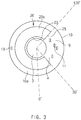
- FIG. 3 is a bottom view of FIG. 2 .
- a secondary battery includes a jelly-roll 10 in which an electrode and a separator are stacked to cross each other and which is wound around a central core 3, a plurality of multi-tab parts 11 extending from the electrode and formed on a predetermined area a at an end 10a of the jelly-roll 10, a can member 1 accommodating the jelly-roll 10, and an insulation member 20 disposed adjacent to the end 10a to insulate the can member 1 from the jelly-roll 10.
- the insulation member 20 has a central hole 23 punched in a center of the insulation member 20 so that the central core 3 passes therethrough and a tab hole 25 punched around the central hole 23 to correspond to the plurality of multi-tab parts 11 so that the plurality of multi-tab parts 11 pass therethrough.
- the jelly-roll 10 may be manufactured by winding a stack, in which a positive electrode, a separator, and a negative electrode are stacked, in a jelly-roll shape.
- the positive electrode may be an aluminum plate and include a positive electrode active material portion coated with a positive electrode active material and a positive electrode non-coating portion which is not coated with the positive electrode active material.
- the negative electrode may be a copper plate and include a negative electrode active material portion coated with a negative electrode active material and a negative electrode non-coating portion which is not coated with the negative electrode active material.
- the separator may be stacked between the positive electrode and the negative electrode to separate the positive electrode from the negative electrode.
- the electrode according to the present invention may be at least one of the positive electrode and the negative electrode, which form the jelly-roll.
- the plurality of multi-tab parts 11 and a tab part 13 may be bonded to each other by notching the non-coating portion of the electrode to extend from the electrode or by welding the plurality of multi-tab parts 11 and the tab part 13 to the non-coating portion of the electrode.
- the insulation member 20 may be installed on all the jelly-roll 10 including the multi-tab parts 11 formed by the notching or welding.
- the plurality of multi-tab parts 11 may be formed on the end 10a of the jelly-roll 10.
- the plurality of multi-tab parts 11 may be formed on a lower end of the end 10a of the jelly-roll 10.
- the plurality of multi-tab parts 11 may be negative tabs extending from the negative electrode of the electrode.
- the plurality of multi-tab parts 11 may have different lengths to be electrically connected to the can member 1.
- Each of the plurality of multi-tab parts 11 may have a length that gradually decreases from the end 10a of the jelly-roll 10 toward the central core 3 so as to be easily electrically connected to the can member 1.
- the predetermined area a may correspond to an area corresponding to an angle of 30° to 120° (see FIG. 3 ) about the central core 3 at the end 10a of the jelly-roll 10.
- the plurality of multi-tab parts 11 may be formed on the predetermined area a at the end 10a of the jelly-roll 10 to standardize formation positions of the plurality of multi-tab parts, thereby facilitating the manufacture.
- the can member 1 may be a container made of a metal material and having a shape that is opened substantially upward in the cylindrical secondary battery.
- iron (Fe) on which aluminum (Al) or nickel (Ni), which is light and easy to cope with corrosion, is plated may be used as the metal material.
- the central hole 23 is punched in the center, and the tab hole 25 is punched around the central hole 23.
- the insulation member may have a circumferential length less than that of the end 10a of the jelly-roll 20.
- the tab part 13 when the tab part 13 is formed on the circumference of the end 10a of the jelly-roll 20, the tab part 13 may extend through the outside of an edge of the insulation member 20. Thus, an additional tab part 13 may be easily formed on the end 10a.
- the central core 3 may pass through the central hole 23.
- an electrode tab (not shown) formed on the end 10a of the jelly-roll 10 may pass through the central hole 23.
- the tab hole 25 may be formed in a position corresponding to that of the predetermined area a at the end 10a of the jelly-roll 10.
- the tab hole 25 may be formed in a position corresponding to the predetermined area a of the end 10a in the insulation member 20 to induce the multi-tab part 11 so that the multi-tab part 11 formed on the predetermined area a of the end 10a of the jelly-roll 10 easily passes through the tab hole 25.
- the tab hole 25 may be punched at a position corresponding to the predetermined area a of the end 10a in the insulation member 20 and be opened up to a portion of the edge of the insulation member 20.
- the tab hole 25 may communicate with the central hole 23.
- a body 20a of the insulation member 20 may be minimized to reduce a weight.
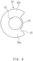
- FIG. 4 is a plan view illustrating only an insulation member of a secondary battery according to another embodiment of the present invention.
- a central hole 23 and a tan hole 25 of an insulation member 10 are formed to be separated from each other.
- a boundary part 27 may be formed between the central hole 23 and the tab hole 25.
- a central core 3 may be inserted into and coupled to the central hole 23 by the boundary part 27, and thus, the insulation member 10 may be guided to be fixed in a proper position at an end 10a of the jelly-roll 10, and the position of the insulation member 10 may be stably maintained without moving in a transverse direction.
- the jelly-roll including the multi-tab and the can member may be insulated from each other.
- the insulation member may be stably fixed between the jelly-roll including the multi-tab and the can member.
- the position at which the multi-tab is formed may be standardized to easily manufacture the multi-tab.
- the insulation member installed between the jelly-roll including the multi-tab and the can member may be minimized in size to reduce the weight of the secondary battery.
- the insulation member installed between the jelly-roll including the multi-tab and the can member may have the circumference less than that of the end of the jelly-roll to facilitate the additional design of the tab part.
- the present invention may be applied to the multi-tab that is manufactured through various methods.
- the present invention may be easily applied to the negative electrode multi-tab.
Landscapes
- Chemical & Material Sciences (AREA)
- Chemical Kinetics & Catalysis (AREA)
- Electrochemistry (AREA)
- General Chemical & Material Sciences (AREA)
- Engineering & Computer Science (AREA)
- Manufacturing & Machinery (AREA)
- Inorganic Chemistry (AREA)
- Connection Of Batteries Or Terminals (AREA)
- Secondary Cells (AREA)
Abstract
Description
- The present application claims the benefit of the priority of Korean Patent Application No.
10-2017-0068857 filed on June 02, 2017 - The present invention relates to a secondary battery, and more particularly, to a secondary battery provided with a multi-tab.
- Batteries (cells) that generate electric energy through physical or chemical reaction to supply the generated electric energy to the outside are used when AC power to be supplied to the building is not obtained, or DC power is required according to the living environments surrounded by various electric and electronic devices.
- Among such batteries, primary batteries and secondary batteries, which are chemical batteries using chemical reaction, are being generally used. The primary batteries are consumable batteries which are collectively referred to as dry batteries. Also, secondary batteries are rechargeable batteries that are manufactured by using a material in a redox process between current and a substance is repeatable several times. When the reduction reaction is performed on the material by the current, power is charged, and when the oxidation reaction is performed on the material, power is discharged. Such the charging-discharging is repeatedly performed to generate electricity.
- A lithium ion battery of the secondary batteries is manufactured through the following processes. An active material is applied to each of a positive electrode conductive foil and a negative electrode conductive foil at a predetermined thickness, and a separator is disposed between the positive electrode conductive foil and the negative electrode conductive foil, and then, an electrode assembly, in which the positive electrode conductive foil, the separator, and the negative electrode conductive foil are wound several times in a jelly-roll or cylindrical shape, is accommodated into a cylindrical or prismatic can, a pouch, and the like to seal the resultant product, thereby manufacturing the lithium ion battery.
- An electrode assembly and a secondary battery including the same according to the related art are disclosed in Korea Patent Publication No.
10-2008-0047165 - In the secondary battery according to the related art, since the position of the multi-tab is not constant, it is difficult to design an insulator formed between the electrode assembly and a can.
- Thus, it is necessary to develop an insulator that is suitable for the multi-tab.
- The present invention has been made to solve the above problem, and thus an object of the present is to provide a secondary battery including an insulation member that is suitable for a multi-tab.
- A secondary battery according to an embodiment of the present invention includes a jelly-roll in which an electrode and a separator are stacked to cross each other and which is wound around a central core, a plurality of multi-tab parts extending from the electrode and formed on a predetermined area at an end of the jelly-roll, a can member accommodating the jelly-roll, and an insulation member disposed adjacent to the end to insulate the can member from the jelly-roll, wherein the insulation member includes a central hole punched in a center of the insulation member so that the central core passes therethrough and a tab hole punched around the central hole to correspond to the plurality of multi-tab parts so that the plurality of multi-tab parts pass therethrough.
- The predetermined area may correspond to an area corresponding to an angle of 30° to 120° about the central core.
- The tab hole may be formed in a position corresponding to that of the predetermined area.
- The insulation member may be formed so that the central hole and the tab hole are separated from each other.
- The insulation member may be formed so that the central hole and the tab hole communicate with each other.
- The insulation member may have a circumference less than that of the end.
- The secondary battery may further include a tab part formed on the end and disposed outside an edge of the insulation member.
- The tab hole may be opened up to a portion of an edge of the insulation member.
- The plurality of multi-tab parts and the tab part may be provided on the jelly-roll through welding or notching.
- The end may be a lower end of the jelly-roll.
- According to the present invention, the jelly-roll including the multi-tab and the can member may be insulated from each other.
- According to the present invention, the insulation member may be stably fixed between the jelly-roll including the multi-tab and the can member.
- According to the present invention, the position at which the multi-tab is formed may be standardized to easily manufacture the multi-tab.
- According to the present invention, the insulation member installed between the jelly-roll including the multi-tab and the can member may be minimized in size to reduce the weight of the secondary battery.
- According to the present invention, the insulation member installed between the jelly-roll including the multi-tab and the can member may have the circumference less than that of the end of the jelly-roll to facilitate the additional design of the tab part.
- The present invention may be applied to the multi-tab that is manufactured through various methods.
- The present invention may be easily applied to the negative electrode multi-tab.
-
-
FIG. 1 is a perspective view of a secondary battery according to an embodiment of the present invention. -
FIG. 2 is a side view illustrating only a jelly-roll and a multi-tab part of the secondary battery according to the present invention. -
FIG. 3 is a bottom view ofFIG. 2 . -
FIG. 4 is a plan view illustrating only an insulation member of a secondary battery according to another embodiment the present invention. - Hereinafter, a secondary battery according to an exemplary embodiment of the present invention will be described in detail with reference to the accompanying drawings.
- Terms or words used in the specification and claims should not be construed as limited to a lexical meaning, and should be understood as appropriate notions by the inventor based on that he/she is able to define terms to describe his/her invention in the best way to be seen by others. Therefore, embodiments and drawings described herein are simply exemplary and not exhaustive, and it will be understood that various equivalents may be made to take the place of the embodiments.
- In the drawings, the dimension of each of components or a specific portion constituting the component is exaggerated, omitted, or schematically illustrated for convenience in description and clarity. Thus, the dimension of each element does not entirely reflect an actual size. Moreover, detailed descriptions related to well-known functions or configurations will be ruled out in order not to unnecessarily obscure subject matters of the present invention.
-
FIG. 1 is a perspective view of a secondary battery according to an embodiment of the present invention,FIG. 2 is a side view illustrating only a jelly-roll and a multi-tab part of the secondary battery according to the present invention, andFIG. 3 is a bottom view ofFIG. 2 . - As illustrated in
FIGS. 1 to 3 , a secondary battery according to an embodiment of the present invention includes a jelly-roll 10 in which an electrode and a separator are stacked to cross each other and which is wound around acentral core 3, a plurality ofmulti-tab parts 11 extending from the electrode and formed on a predetermined area a at anend 10a of the jelly-roll 10, a can member 1 accommodating the jelly-roll 10, and aninsulation member 20 disposed adjacent to theend 10a to insulate the can member 1 from the jelly-roll 10. Theinsulation member 20 has acentral hole 23 punched in a center of theinsulation member 20 so that thecentral core 3 passes therethrough and atab hole 25 punched around thecentral hole 23 to correspond to the plurality ofmulti-tab parts 11 so that the plurality ofmulti-tab parts 11 pass therethrough. - The jelly-
roll 10 may be manufactured by winding a stack, in which a positive electrode, a separator, and a negative electrode are stacked, in a jelly-roll shape. - The positive electrode may be an aluminum plate and include a positive electrode active material portion coated with a positive electrode active material and a positive electrode non-coating portion which is not coated with the positive electrode active material.
- The negative electrode may be a copper plate and include a negative electrode active material portion coated with a negative electrode active material and a negative electrode non-coating portion which is not coated with the negative electrode active material.
- The separator may be stacked between the positive electrode and the negative electrode to separate the positive electrode from the negative electrode.
- As described above, the electrode according to the present invention may be at least one of the positive electrode and the negative electrode, which form the jelly-roll.
- The plurality of
multi-tab parts 11 and atab part 13 may be bonded to each other by notching the non-coating portion of the electrode to extend from the electrode or by welding the plurality ofmulti-tab parts 11 and thetab part 13 to the non-coating portion of the electrode. - Thus, the
insulation member 20 may be installed on all the jelly-roll 10 including themulti-tab parts 11 formed by the notching or welding. - The plurality of
multi-tab parts 11 may be formed on theend 10a of the jelly-roll 10. - The plurality of
multi-tab parts 11 may be formed on a lower end of theend 10a of the jelly-roll 10. - The plurality of
multi-tab parts 11 may be negative tabs extending from the negative electrode of the electrode. - The plurality of
multi-tab parts 11 may have different lengths to be electrically connected to the can member 1. - Each of the plurality of
multi-tab parts 11 may have a length that gradually decreases from theend 10a of the jelly-roll 10 toward thecentral core 3 so as to be easily electrically connected to the can member 1. - The predetermined area a may correspond to an area corresponding to an angle of 30° to 120° (see
FIG. 3 ) about thecentral core 3 at theend 10a of the jelly-roll 10. - As described above, the plurality of
multi-tab parts 11 may be formed on the predetermined area a at theend 10a of the jelly-roll 10 to standardize formation positions of the plurality of multi-tab parts, thereby facilitating the manufacture. - The can member 1 may be a container made of a metal material and having a shape that is opened substantially upward in the cylindrical secondary battery. Here, iron (Fe), on which aluminum (Al) or nickel (Ni), which is light and easy to cope with corrosion, is plated may be used as the metal material.
- In the
insulation member 20, thecentral hole 23 is punched in the center, and thetab hole 25 is punched around thecentral hole 23. - The insulation member may have a circumferential length less than that of the
end 10a of the jelly-roll 20. - Also, when the
tab part 13 is formed on the circumference of theend 10a of the jelly-roll 20, thetab part 13 may extend through the outside of an edge of theinsulation member 20. Thus, anadditional tab part 13 may be easily formed on theend 10a. - The
central core 3 may pass through thecentral hole 23. In some case, an electrode tab (not shown) formed on theend 10a of the jelly-roll 10 may pass through thecentral hole 23. - The
tab hole 25 may be formed in a position corresponding to that of the predetermined area a at theend 10a of the jelly-roll 10. - That is, when the
insulation member 20 is installed on theend 10a of the jelly-roll 10, thetab hole 25 may be formed in a position corresponding to the predetermined area a of theend 10a in theinsulation member 20 to induce themulti-tab part 11 so that themulti-tab part 11 formed on the predetermined area a of theend 10a of the jelly-roll 10 easily passes through thetab hole 25. - Also, the
tab hole 25 may be punched at a position corresponding to the predetermined area a of theend 10a in theinsulation member 20 and be opened up to a portion of the edge of theinsulation member 20. - Also, the
tab hole 25 may communicate with thecentral hole 23. - In addition, when the
tab hole 25 communicating with thecentral hole 23 is formed in theinsulation member 20, abody 20a of theinsulation member 20 may be minimized to reduce a weight. -
FIG. 4 is a plan view illustrating only an insulation member of a secondary battery according to another embodiment of the present invention. - As illustrated in
FIG. 4 , in a secondary battery according to another embodiment of the present invention, acentral hole 23 and atan hole 25 of aninsulation member 10 are formed to be separated from each other. - To separate the
central hole 23 from thetab hole 25, aboundary part 27 may be formed between thecentral hole 23 and thetab hole 25. - A
central core 3 may be inserted into and coupled to thecentral hole 23 by theboundary part 27, and thus, theinsulation member 10 may be guided to be fixed in a proper position at anend 10a of the jelly-roll 10, and the position of theinsulation member 10 may be stably maintained without moving in a transverse direction. - As described above, according to the present invention, the jelly-roll including the multi-tab and the can member may be insulated from each other.
- According to the present invention, the insulation member may be stably fixed between the jelly-roll including the multi-tab and the can member.
- According to the present invention, the position at which the multi-tab is formed may be standardized to easily manufacture the multi-tab.
- According to the present invention, the insulation member installed between the jelly-roll including the multi-tab and the can member may be minimized in size to reduce the weight of the secondary battery.
- According to the present invention, the insulation member installed between the jelly-roll including the multi-tab and the can member may have the circumference less than that of the end of the jelly-roll to facilitate the additional design of the tab part.
- The present invention may be applied to the multi-tab that is manufactured through various methods.
- The present invention may be easily applied to the negative electrode multi-tab.
- Although the secondary battery according to the present invention has been described above with reference to the exemplary drawings, various changes and modifications may be made thereto by one skilled in the art without departing from the scope and spirit of the invention as set forth in the appended claims.
Claims (10)
- A secondary battery comprising:a jelly-roll (10) in which an electrode and a separator are stacked to cross each other and which is wound around a central core (3);a plurality of multi-tab parts (11) extending from the electrode and formed on a predetermined area (a) at an end (10a) of the jelly-roll (10);a can member (1) accommodating the jelly-roll (10); andan insulation member (20) disposed adjacent to the end (10a) to insulate the can member (1) from the jelly-roll (10),wherein the insulation member (20) comprises:a central hole (23) punched in a center of the insulation member (20) so that the central core (3) passes therethrough; anda tab hole (25) punched around the central hole (23) to correspond to the plurality of multi-tab parts (11) so that the plurality of multi-tab parts (11) pass therethrough.
- The secondary battery of claim 1, wherein the predetermined area (a) corresponds to an area corresponding to an angle of 30° to 120° about the central core (3).
- The secondary battery of claim 1, wherein the tab hole (25) is formed in a position corresponding to that of the predetermined area (a).
- The secondary battery of claim 1, wherein the insulation member (20) is formed so that the central hole (23) and the tab hole (25) are separated from each other.
- The secondary battery of claim 1, wherein the insulation member (20) is formed so that the central hole (23) and the tab hole (25) communicate with each other.
- The secondary battery of claim 1, wherein the insulation member (20) has a circumference less than that of the end (10a).
- The secondary battery of claim 6, further comprising a tab part (13) formed on the end (10a) and disposed outside an edge of the insulation member (20).
- The secondary battery of claim 1, wherein the tab hole (25) is opened up to a portion of an edge of the insulation member (20).
- The secondary battery of claim 7, wherein the plurality of multi-tab parts (11) and the tab part (13) are provided on the jelly-roll (10) through welding or notching.
- The secondary battery of claim 1, wherein the end (10a) is a lower end of the jelly-roll (10).
Applications Claiming Priority (2)
| Application Number | Priority Date | Filing Date | Title |
|---|---|---|---|
| KR1020170068857A KR102179486B1 (en) | 2017-06-02 | 2017-06-02 | Secondary battery |
| PCT/KR2018/006172 WO2018221965A1 (en) | 2017-06-02 | 2018-05-30 | Secondary battery |
Publications (3)
| Publication Number | Publication Date |
|---|---|
| EP3534426A1 true EP3534426A1 (en) | 2019-09-04 |
| EP3534426A4 EP3534426A4 (en) | 2020-02-12 |
| EP3534426B1 EP3534426B1 (en) | 2024-02-28 |
Family
ID=64455544
Family Applications (1)
| Application Number | Title | Priority Date | Filing Date |
|---|---|---|---|
| EP18810767.6A Active EP3534426B1 (en) | 2017-06-02 | 2018-05-30 | Secondary battery |
Country Status (5)
| Country | Link |
|---|---|
| US (1) | US11152638B2 (en) |
| EP (1) | EP3534426B1 (en) |
| KR (1) | KR102179486B1 (en) |
| CN (1) | CN110226244B (en) |
| WO (1) | WO2018221965A1 (en) |
Families Citing this family (6)
| Publication number | Priority date | Publication date | Assignee | Title |
|---|---|---|---|---|
| USD899355S1 (en) * | 2016-08-15 | 2020-10-20 | Milwaukee Electric Tool Corporation | Battery |
| PL3526827T3 (en) | 2016-10-14 | 2022-11-28 | Milwaukee Electric Tool Corporation | Battery pack |
| JP7219148B2 (en) * | 2018-04-25 | 2023-02-07 | 住友化学株式会社 | Inspection system and method for driving inspection system |
| USD911926S1 (en) * | 2019-03-13 | 2021-03-02 | Ningbo Roca Superior Products E-Commerce Co., Ltd | Rechargeable battery |
| USD929315S1 (en) * | 2019-03-15 | 2021-08-31 | The Coleman Company, Inc. | Interchangeable battery |
| JP7255013B2 (en) | 2019-11-01 | 2023-04-10 | エルジー エナジー ソリューション リミテッド | Secondary battery and manufacturing method thereof |
Family Cites Families (22)
| Publication number | Priority date | Publication date | Assignee | Title |
|---|---|---|---|---|
| JPH0794165A (en) | 1993-09-21 | 1995-04-07 | Hitachi Maxell Ltd | Organic electrolyte battery |
| JP3519953B2 (en) * | 1998-08-27 | 2004-04-19 | 三洋電機株式会社 | Rechargeable battery |
| JP2002164044A (en) * | 2000-11-24 | 2002-06-07 | Nec Corp | Electrode wound-type battery and method of manufacturing the same |
| KR100515832B1 (en) | 2003-04-24 | 2005-09-21 | 삼성에스디아이 주식회사 | Electrode assembly of secondary battery |
| CN2833901Y (en) * | 2005-08-19 | 2006-11-01 | 周基平 | Cylindrical lithium cell |
| KR100821221B1 (en) | 2006-08-21 | 2008-04-10 | 엘지전자 주식회사 | Schedule sharing service method using wireless internet and mobile communication terminal therefor |
| KR20080047165A (en) | 2006-11-24 | 2008-05-28 | 주식회사 엘지화학 | Electrode assembly and secondary battery comprising the same |
| KR100954590B1 (en) | 2008-02-20 | 2010-04-26 | 삼성에스디아이 주식회사 | Electrode assembly and secondary battery using the same |
| CN101604737B (en) * | 2008-06-13 | 2014-03-12 | 深圳市比克电池有限公司 | Secondary battery |
| KR101250196B1 (en) * | 2010-01-12 | 2013-04-03 | 주식회사 엘지화학 | Cylindrical Secondary Battery having Two More Cathode Taps |
| US20110262779A1 (en) | 2010-04-23 | 2011-10-27 | Hossein Maleki | Electrochemical Cell with Reduced Magnetic Field Emission and Corresponding Devices |
| KR101147237B1 (en) * | 2010-07-12 | 2012-05-18 | 삼성에스디아이 주식회사 | Electrode assembly and rechargeable battery including the same |
| WO2013002496A2 (en) * | 2011-06-30 | 2013-01-03 | 주식회사 엘지화학 | Secondary battery provided with insulator |
| JP5838073B2 (en) | 2011-11-04 | 2015-12-24 | 株式会社日立製作所 | Cylindrical wound battery |
| KR101416763B1 (en) | 2012-12-31 | 2014-07-11 | 킴스테크날리지 주식회사 | Terminal of Electric Energy Storage Device And Assembling Method thereof |
| KR101975392B1 (en) * | 2013-01-17 | 2019-05-07 | 삼성에스디아이 주식회사 | Rechargeable battery |
| CN107112487B (en) * | 2014-12-16 | 2020-08-07 | 三洋电机株式会社 | Cylindrical battery |
| KR102141240B1 (en) * | 2015-04-30 | 2020-08-04 | 주식회사 엘지화학 | Electrode assembly and secondary battery comprising the same |
| KR101958762B1 (en) * | 2015-07-17 | 2019-03-15 | 주식회사 엘지화학 | Cylindrical secondary battery |
| KR102459618B1 (en) * | 2015-09-23 | 2022-10-27 | 삼성에스디아이 주식회사 | secondary battery |
| KR102384021B1 (en) * | 2015-09-24 | 2022-04-07 | 삼성에스디아이 주식회사 | Electrode assembly and secondary battery having the same |
| KR102547065B1 (en) * | 2016-02-29 | 2023-06-23 | 삼성에스디아이 주식회사 | Secondary battery |
-
2017
- 2017-06-02 KR KR1020170068857A patent/KR102179486B1/en active IP Right Grant
-
2018
- 2018-05-30 EP EP18810767.6A patent/EP3534426B1/en active Active
- 2018-05-30 US US16/464,531 patent/US11152638B2/en active Active
- 2018-05-30 CN CN201880007303.2A patent/CN110226244B/en active Active
- 2018-05-30 WO PCT/KR2018/006172 patent/WO2018221965A1/en unknown
Also Published As
| Publication number | Publication date |
|---|---|
| EP3534426B1 (en) | 2024-02-28 |
| US11152638B2 (en) | 2021-10-19 |
| KR20180132242A (en) | 2018-12-12 |
| KR102179486B1 (en) | 2020-11-16 |
| CN110226244A (en) | 2019-09-10 |
| US20190348703A1 (en) | 2019-11-14 |
| WO2018221965A1 (en) | 2018-12-06 |
| EP3534426A4 (en) | 2020-02-12 |
| CN110226244B (en) | 2022-08-16 |
Similar Documents
| Publication | Publication Date | Title |
|---|---|---|
| EP3534426B1 (en) | Secondary battery | |
| CN110476273B (en) | Secondary battery and method of manufacturing the same | |
| EP3477729B1 (en) | Rechargeable lithium ion button cell battery | |
| US10790486B2 (en) | Secondary battery and method for manufacturing the same | |
| US10446802B2 (en) | Curved secondary battery and method of manufacturing the same | |
| US10062871B2 (en) | Rechargeable battery with tabs | |
| US11349182B2 (en) | Electrode assembly | |
| EP3614451B1 (en) | Secondary battery | |
| US9825326B2 (en) | Rechargeable battery | |
| EP3136471B1 (en) | Battery | |
| EP3401992B1 (en) | Secondary battery | |
| EP2860796A2 (en) | Rechargeable battery having short-circuit protrusion | |
| US20170170450A1 (en) | Rechargeable battery | |
| US11749866B2 (en) | Secondary battery | |
| US20180351206A1 (en) | Secondary battery | |
| EP3330727A2 (en) | Apparatus for measuring change in thickness of electrode in secondary battery and secondary battery having same apparatus mounted thereto | |
| KR102106455B1 (en) | Secondary battery | |
| KR20160137218A (en) | Secondary battery |
Legal Events
| Date | Code | Title | Description |
|---|---|---|---|
| STAA | Information on the status of an ep patent application or granted ep patent |
Free format text: STATUS: THE INTERNATIONAL PUBLICATION HAS BEEN MADE |
|
| PUAI | Public reference made under article 153(3) epc to a published international application that has entered the european phase |
Free format text: ORIGINAL CODE: 0009012 |
|
| STAA | Information on the status of an ep patent application or granted ep patent |
Free format text: STATUS: REQUEST FOR EXAMINATION WAS MADE |
|
| 17P | Request for examination filed |
Effective date: 20190529 |
|
| AK | Designated contracting states |
Kind code of ref document: A1 Designated state(s): AL AT BE BG CH CY CZ DE DK EE ES FI FR GB GR HR HU IE IS IT LI LT LU LV MC MK MT NL NO PL PT RO RS SE SI SK SM TR |
|
| AX | Request for extension of the european patent |
Extension state: BA ME |
|
| A4 | Supplementary search report drawn up and despatched |
Effective date: 20200114 |
|
| RIC1 | Information provided on ipc code assigned before grant |
Ipc: H01M 2/06 20060101AFI20200108BHEP Ipc: H01M 2/02 20060101ALI20200108BHEP Ipc: H01M 10/052 20100101ALN20200108BHEP Ipc: H01M 10/04 20060101ALI20200108BHEP Ipc: H01M 2/30 20060101ALN20200108BHEP Ipc: H01M 10/0587 20100101ALI20200108BHEP Ipc: H01M 2/26 20060101ALI20200108BHEP Ipc: H01M 2/04 20060101ALI20200108BHEP |
|
| DAV | Request for validation of the european patent (deleted) | ||
| DAX | Request for extension of the european patent (deleted) | ||
| STAA | Information on the status of an ep patent application or granted ep patent |
Free format text: STATUS: EXAMINATION IS IN PROGRESS |
|
| 17Q | First examination report despatched |
Effective date: 20211117 |
|
| RAP1 | Party data changed (applicant data changed or rights of an application transferred) |
Owner name: LG ENERGY SOLUTION LTD. |
|
| RAP3 | Party data changed (applicant data changed or rights of an application transferred) |
Owner name: LG ENERGY SOLUTION, LTD. |
|
| REG | Reference to a national code |
Ref country code: DE Ref legal event code: R079 Ref document number: 602018065932 Country of ref document: DE Free format text: PREVIOUS MAIN CLASS: H01M0002060000 Ipc: H01M0010040000 Ref country code: DE Free format text: PREVIOUS MAIN CLASS: H01M0002060000 |
|
| RIC1 | Information provided on ipc code assigned before grant |
Ipc: H01M 10/052 20100101ALN20230429BHEP Ipc: H01M 50/107 20210101ALI20230429BHEP Ipc: H01M 50/538 20210101ALI20230429BHEP Ipc: H01M 10/0587 20100101ALI20230429BHEP Ipc: H01M 10/04 20060101AFI20230429BHEP |
|
| GRAP | Despatch of communication of intention to grant a patent |
Free format text: ORIGINAL CODE: EPIDOSNIGR1 |
|
| STAA | Information on the status of an ep patent application or granted ep patent |
Free format text: STATUS: GRANT OF PATENT IS INTENDED |
|
| RIC1 | Information provided on ipc code assigned before grant |
Ipc: H01M 10/052 20100101ALN20231115BHEP Ipc: H01M 50/107 20210101ALI20231115BHEP Ipc: H01M 50/538 20210101ALI20231115BHEP Ipc: H01M 10/0587 20100101ALI20231115BHEP Ipc: H01M 10/04 20060101AFI20231115BHEP |
|
| RIC1 | Information provided on ipc code assigned before grant |
Ipc: H01M 10/052 20100101ALN20231117BHEP Ipc: H01M 50/107 20210101ALI20231117BHEP Ipc: H01M 50/538 20210101ALI20231117BHEP Ipc: H01M 10/0587 20100101ALI20231117BHEP Ipc: H01M 10/04 20060101AFI20231117BHEP |
|
| INTG | Intention to grant announced |
Effective date: 20231204 |
|
| GRAS | Grant fee paid |
Free format text: ORIGINAL CODE: EPIDOSNIGR3 |
|
| GRAA | (expected) grant |
Free format text: ORIGINAL CODE: 0009210 |
|
| STAA | Information on the status of an ep patent application or granted ep patent |
Free format text: STATUS: THE PATENT HAS BEEN GRANTED |
|
| P01 | Opt-out of the competence of the unified patent court (upc) registered |
Effective date: 20240105 |
|
| AK | Designated contracting states |
Kind code of ref document: B1 Designated state(s): AL AT BE BG CH CY CZ DE DK EE ES FI FR GB GR HR HU IE IS IT LI LT LU LV MC MK MT NL NO PL PT RO RS SE SI SK SM TR |
|
| REG | Reference to a national code |
Ref country code: GB Ref legal event code: FG4D |
|
| REG | Reference to a national code |
Ref country code: CH Ref legal event code: EP |
|
| REG | Reference to a national code |
Ref country code: DE Ref legal event code: R096 Ref document number: 602018065932 Country of ref document: DE |
|
| REG | Reference to a national code |
Ref country code: IE Ref legal event code: FG4D |