EP3534098A1 - Raw material charging apparatus and charging method therefor - Google Patents
Raw material charging apparatus and charging method therefor Download PDFInfo
- Publication number
- EP3534098A1 EP3534098A1 EP16919841.3A EP16919841A EP3534098A1 EP 3534098 A1 EP3534098 A1 EP 3534098A1 EP 16919841 A EP16919841 A EP 16919841A EP 3534098 A1 EP3534098 A1 EP 3534098A1
- Authority
- EP
- European Patent Office
- Prior art keywords
- raw material
- charging
- charging chute
- movable roll
- mixed raw
- Prior art date
- Legal status (The legal status is an assumption and is not a legal conclusion. Google has not performed a legal analysis and makes no representation as to the accuracy of the status listed.)
- Withdrawn
Links
Images







Classifications
-
- F—MECHANICAL ENGINEERING; LIGHTING; HEATING; WEAPONS; BLASTING
- F27—FURNACES; KILNS; OVENS; RETORTS
- F27B—FURNACES, KILNS, OVENS OR RETORTS IN GENERAL; OPEN SINTERING OR LIKE APPARATUS
- F27B21/00—Open or uncovered sintering apparatus; Other heat-treatment apparatus of like construction
- F27B21/02—Sintering grates or tables
-
- C—CHEMISTRY; METALLURGY
- C22—METALLURGY; FERROUS OR NON-FERROUS ALLOYS; TREATMENT OF ALLOYS OR NON-FERROUS METALS
- C22B—PRODUCTION AND REFINING OF METALS; PRETREATMENT OF RAW MATERIALS
- C22B1/00—Preliminary treatment of ores or scrap
- C22B1/14—Agglomerating; Briquetting; Binding; Granulating
- C22B1/16—Sintering; Agglomerating
- C22B1/20—Sintering; Agglomerating in sintering machines with movable grates
-
- F—MECHANICAL ENGINEERING; LIGHTING; HEATING; WEAPONS; BLASTING
- F27—FURNACES; KILNS; OVENS; RETORTS
- F27B—FURNACES, KILNS, OVENS OR RETORTS IN GENERAL; OPEN SINTERING OR LIKE APPARATUS
- F27B21/00—Open or uncovered sintering apparatus; Other heat-treatment apparatus of like construction
-
- F—MECHANICAL ENGINEERING; LIGHTING; HEATING; WEAPONS; BLASTING
- F27—FURNACES; KILNS; OVENS; RETORTS
- F27D—DETAILS OR ACCESSORIES OF FURNACES, KILNS, OVENS OR RETORTS, IN SO FAR AS THEY ARE OF KINDS OCCURRING IN MORE THAN ONE KIND OF FURNACE
- F27D3/00—Charging; Discharging; Manipulation of charge
- F27D3/0033—Charging; Discharging; Manipulation of charge charging of particulate material
-
- F—MECHANICAL ENGINEERING; LIGHTING; HEATING; WEAPONS; BLASTING
- F27—FURNACES; KILNS; OVENS; RETORTS
- F27D—DETAILS OR ACCESSORIES OF FURNACES, KILNS, OVENS OR RETORTS, IN SO FAR AS THEY ARE OF KINDS OCCURRING IN MORE THAN ONE KIND OF FURNACE
- F27D3/00—Charging; Discharging; Manipulation of charge
- F27D3/10—Charging directly from hoppers or shoots
-
- F—MECHANICAL ENGINEERING; LIGHTING; HEATING; WEAPONS; BLASTING
- F27—FURNACES; KILNS; OVENS; RETORTS
- F27D—DETAILS OR ACCESSORIES OF FURNACES, KILNS, OVENS OR RETORTS, IN SO FAR AS THEY ARE OF KINDS OCCURRING IN MORE THAN ONE KIND OF FURNACE
- F27D3/00—Charging; Discharging; Manipulation of charge
- F27D2003/0001—Positioning the charge
- F27D2003/0002—Positioning the charge involving positioning devices, e.g. buffers, buffer zones
-
- F—MECHANICAL ENGINEERING; LIGHTING; HEATING; WEAPONS; BLASTING
- F27—FURNACES; KILNS; OVENS; RETORTS
- F27D—DETAILS OR ACCESSORIES OF FURNACES, KILNS, OVENS OR RETORTS, IN SO FAR AS THEY ARE OF KINDS OCCURRING IN MORE THAN ONE KIND OF FURNACE
- F27D3/00—Charging; Discharging; Manipulation of charge
- F27D2003/0001—Positioning the charge
- F27D2003/0006—Particulate materials
- F27D2003/0009—Separation of different types of fines, e.g. by a blower
Definitions
- the present invention relates to a raw material charging apparatus and a charging method thereof, and more particularly, to a raw material charging apparatus and method, which are capable of improving quality and productivity of sintered ore by rapidly responding to fluctuation in operation.
- the sintering mixed raw material is charged into the sintering car by using a charging chute constituted by an inclined plate and a plurality of rolls or rods.
- the charging chute generates grain segregation so that large and heavy particles of the sintering mixed raw material are charged into a lower layer of the sintering car, and small and light particles are charged in the upper layer to induce segregation charging so that air permeability is good during the sintering.
- the fine raw material of the sintering mixed raw material is attached to the charging chute to reduce the moving speed of the sintering mixed raw material moving along the charging chute, it is necessary to increase in inclination of the charging chute so as to maintain the moving speed of the sintering mixed raw material. Also, in a case in which it is necessary to increase in layer thickness rather than the normal operation, a lower end of the charging chute may contact the raw material layer to press the a surface layer portion, thereby reducing the air permeability during the sintering.
- the present invention provides a raw material charging apparatus and a charging method thereof, which are capable of quickly responding to fluctuation in operation.
- the present invention provides a raw material charging apparatus and a charging method thereof, which are capable of improving air permeability of a raw material layer to improve quality and productivity of sintered ore.
- a raw material charging apparatus may include a charging chute disposed between a raw material feeding part and a container to charge a raw material into the container, wherein the charging chute may include a movable roll, which is movable in a direction crossing a width direction of the charging chute, in at least a portion thereof.
- the charging chute may include a plurality of fixed rolls that are disposed parallel to each other to form a moving path for the raw material, and the movable roll may be disposed below the fixed rolls from which the raw material breaks away into the container.
- the charging chute may include an upper charging chute having an area and a plate shape to form the moving path for the raw material, and the movable roll may be disposed on a lower portion of the upper charging chute from which the raw material breaks away into the container.
- the movable roll may be disposed at the lowermost end in a direction in which the raw material moves in the charging chute.
- At least a portion of the moving path may have a linear or curved cross-sectional shape.
- At least a portion of the moving path may have a cycloid curved cross-sectional shape.
- the raw material charging apparatus may further include an elevation unit that allows the movable roll to move.
- the elevation unit may include one of a cylinder, a screw shaft, and a hydraulic jack.
- the raw material charging apparatus may further include a driving unit that allows the movable roll to rotate.
- the movable roll may be movable in a vertical direction.
- the movable may be movable in a vertical direction or a direction perpendicular to the moving direction of the raw material that moves along the charging chute.
- the movable roll may move forward and backward in the direction crossing the width direction of the charging chute.
- a raw material charging method for charging a raw material into a container by using a charging chute forming a moving path for the raw material may include: allowing a movable roll disposed on a lower portion of the charging chute, from which the raw material breaks away into the container, to move in a direction crossing a width direction of the charging chute; and feeding the raw material into the charging chute to charge the raw material into the container.
- the allowing of the movable roll to move in the direction crossing the width direction of the charging chute may include allow the movable roll to move according to at least one of a particle size of the raw material, a moisture content of the raw material, or a charging amount of the raw material.
- the movable roll may move to adjust at least one of a speed or height at which the raw material breaks away from the charging chute.
- the movable roll may move to form a space around the movable roll.
- a portion of the raw material may be discharged into the space to charge the raw material into an upper layer portion of a raw material layer formed in the container.
- the movable roll may rotate.
- the movable roll may be provided in the lower portion of the charging chute, and the movable roll may move according to the operation condition fluctuation to control the breakaway angle and speed of the mixed raw material charged into the sintering car. Since the charging pattern is quickly controlled according to the operation fluctuation, the charging fluctuation of the raw material layer within the sintering car may be minimized. Thus, the sintered ore having the predetermined strength while constantly maintaining the air permeability within the raw material layer during the sintering may be manufactured to improve the process efficiency and the productivity.
- FIG. 1 is a schematic view of a raw material charging apparatus according to an embodiment of the present invention.
- a raw material charging apparatus may include a raw material feeding part comprising a raw material hopper 100 and a drum feeder 120 and a charging chute 130.
- the raw material hopper 100 feeds mixed raw materials 1 such as fine iron ore, subsidiary raw materials, and fine coke to the drum feeder 120 via a hopper gate 110, and the drum feeder 120 mixes the mixed raw materials 1 fed therein while rotating to dispense the mixed raw material 1 to the charging chute 130.
- mixed raw materials 1 such as fine iron ore, subsidiary raw materials, and fine coke
- the charging chute 130 is provided between the raw material hopper 1 and a sintering car 200 to charge the mixed raw material 1 into the sintering car 200.
- a plurality of rolls are disposed parallel to each other to form a moving path, through which the mixed raw material moves, in an upper portion thereof.
- the charging chute 130 may have the moving path that is formed in an inclined surface or curved surface shape having a predetermined area.
- the charging chute 130 may have a transverse sectional shape formed in a cycloid curve shape.
- the charging chute 130 may serve to promote vertical segregation so that the mixed raw material having a relatively large particle size is charged into a lower portion of the sintering car 200, and the mixed raw material having a relatively small particle size is charged into an upper portion of the sintering car 200.
- a surface layer portion of the raw material layer may be planarized on a surface smoothing plate 140 provided at a front side with respect to a moving direction of the sintering car 200.
- the surface layer portion is ignited in a igniting burner 150 provided in front of the surface smoothing plate 140, and while the sintering car 200 moves along a sintering section, the fuel material of the mixed raw material within the sintering car 200, for example, the fin coke may be burned by suction force of a wind box to manufacture sintered ore.
- the charging chute 130 may include a movable roll 131 that is movable in a direction crossing a width direction of the charging chute 130.
- the plurality of rolls are disposed parallel to each other to form a moving path for the mixed raw material.
- the movable roll 131 may be provided in the lower portion of the charging chute 130, i.e., the lower portion from which the mixed raw material brakes away so as to be movable in the direction crossing the width direction of the charging chute 130, e.g., in at least one direction of a vertical direction and a diagonal direction.
- the diagonal direction may be a direction crossing the moving direction of the raw material, e.g., a direction perpendicular to the moving direction.
- At least a portion of the plurality of rolls may be a fixed roll 132 of which an installation position is fixed to maintain the moving path for the mixed raw material at a constant angle, and at least a portion may be the movable roll 131 of which an installation position is variable.
- the fixed roll 132 may be provided from the upper portion of the charging chute 130 in a longitudinal direction of the charging chute 130
- the movable roll 131 may be provided from the lower portion of the charging chute 130 in the longitudinal direction of the charging chute 130.
- the movable roll 131 may be provided at the lowermost end of the charging chute 130, at which the mixed raw material breaks away from the moving path formed in the charging chute 130.
- about two or three movable rolls in addition to the roll disposed at the lowermost end may be provided from the lower portion of the charging chute 130.
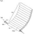
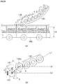
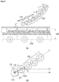
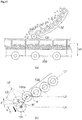
- FIGS. 2 to 5 are perspective and cross-sectional views of the charging chute constituting the raw material charging apparatus according to an embodiment of the present invention
- FIG. 6 is a schematic view illustrating an example of an elevation unit for driving the movable roll.
- the plurality of rolls of the fixed roll 132 may be disposed parallel to each other to form the moving path through which the mixed raw material moves.
- the moving path for the mixed raw material which is formed by the fixed roll 132, may form a moving path having a cycloid curve shape.
- the fixed roll 132 may be rotatably provided to rotate in a moving direction of the mixed raw material and in a direction opposite to the moving direction. This is done for controlling the rotation direction according to a charging amount of the mixed raw material, a moisture content of the mixed raw material, and a particle size of the mixed raw material.
- the movable roll 131 may be provided at the lowermost end of the charging chute 130, for example, may be provided to be movable in an upward/downward direction, e.g., in a vertical direction.
- the movable roll 131 may be provided to be rotatable at a position adjacent to the lowermost fixed roll 132 of the fixed rolls 132, for example, a first fixed roll 132a.
- the movable roll 131 may vertically move according to a change in layer thickness, the particle size of the mixed raw material, or the moisture content of the mixed raw material to adjust a moving distance or moving speed of the mixed raw material discharged to the sintering car 200.
- the movable roll 131 may be provided at the lowermost end of the charging chute 130 and also be provided to be movable in the direction crossing the moving direction of the mixed raw material, e.g., the direction perpendicular to the moving direction.
- the movable roll 131 may be provided to be diagonally movable in a direction that is inclined downward with respect to the moving direction of the mixed raw material.
- the movable roll 131 may be provided to be rotatable at a position adjacent to the lowermost fixed roll 132 of the fixed rolls 132, for example, the first fixed roll 132a.
- the movable roll 131 may diagonally move in the direction perpendicular to the moving direction of the mixed raw material according to the change in layer thickness, the particle size of the mixed raw material, or the moisture content of the mixed raw material to adjust the moving distance or moving speed of the mixed raw material discharged to the sintering car 200.
- an elevation unit 300 supporting the movable roll 131 to allow the movable roll 131 to move in the vertical direction or in the direction crossing the moving direction of the mixed raw material and a driving unit providing rotation force to allow the movable roll 131 to rotate may be provided.
- elevation unit 300 Various constituents such as a cylinder, a screw shaft, a hydraulic jack, and the like may be used as the elevation unit 300.
- the screw shaft is used as the elevation unit 300.
- the elevation unit may include a support frame 310 provided on each of both sides of the movable roll 131 and a connection member 320 connecting the movable roll 131 to the support frame 310 so that the movable roll 131 is movable in the vertical direction.
- a contact member 330 such as a bearing may be provided between the movable roll 131 and the connection member 320 so that the movable roll 131 is rotatably connected to the connection member 320.
- the support frame 310 may be disposed in a longitudinal direction of the movable roll 131, for example, in a direction crossing a width direction of the charging chute 130. That is, since the movable roll 131 is provided to be movable in the vertical direction or the direction crossing the moving direction of the raw material, the support frame 310 may be provided to extend in the moving direction of the movable roll 131. For example, as illustrated in FIG. 2 , when the movable roll 131 moves in the vertical direction, the support frame 310 may be provided to extend in the vertical direction. Also, as illustrated in FIG.
- the support frame 310 when the movable roll 131 moves in the direction crossing the moving direction of the raw material, i.e., in the diagonal direction, the support frame 310 may be disposed in the longitudinal direction of the movable roll 131, for example, in the direction crossing the width direction of the charging chute 130. More particularly, a lower portion of the support frame 310 may be disposed to be inclined downward in the moving direction of the mixed raw material. Thus, the movable roll 131 may ascend and descend in the longitudinal direction of the support frame 310 to move in the diagonal direction.
- a screw thread may be formed on an outer circumferential surface of the support frame 310.
- the support frame 310 may be rotatably provided.
- a grip part 314 may be provided on the support frame 310 so that the support frame 310 directly rotates by a worker.
- a separate power part (not shown) may be connected.
- a sensor (not shown) for measuring a height of the movable roll 131 and a control part (not shown) for controlling the power part by using the result measured by the sensor may be provided so that the support frame 310 rotates to automatically adjust the height of the movable roll 131.
- connection member 320 may have a ring shape surrounding at least a portion of the support frame 310.
- a screw thread may be formed on an inner circumferential surface of the connection member 320 and thus be engaged with a screw thread formed on an outer circumferential surface of the support frame 310. Due to this configuration, when the support frame 310 rotates, the connection member 320 may move in the longitudinal direction of the support frame 310 to allow the movable roll 131 to move in the vertical direction or diagonally move in the direction crossing the moving direction of the raw material.
- the contact member 330 may be provided between the movable roll 131 and the connection member 320 so that the rotation force is not transmitted to the connection member even though the movable roll 131 rotates.
- the bearing may be used as the contact member 330.
- One side of the contact member 330, which is connected to the connection member 320, may become a fixed side, and the other side of the contact member 330, which is connected to the movable roll 131, may become a free side.
- the driving unit may include a driver 350 providing rotation force and a motion transmitting member 340 transmitting the rotation force provided from the driver 350 to the movable roll 131.
- the motion transmitting member 340 may be provided between the movable roll 131 and the contact member 330 and be provided as a gear box including various gears.
- the raw material charging apparatus may adjust a position, e.g., a height of the movable roll 131 without adjusting a position, angle, and height of the charging chute 130 to quickly respond to the fluctuation of the operation condition. That is, when the height of the movable roll 131 is changed, an angle of the lowermost end of the charging chute 130, which has the greatest influence when charging the mixed raw material into the sintering car 200, may be freely adjusted to quickly response the fluctuation of the operation condition.
- the movable roll 131 when the movable roll 131 is disposed to be movable in the vertical direction, the movable roll 131 may have a maximum height of the raw material layer that is capable of being changed into the sintering car 200, for example, a height corresponding to 1500 mm (layer thickness) as an initial height.
- the initial height herein means a maximum height when the movable roll 131 moves in the vertical direction, and the movable roll 131 may only move downward from the initial height. This is done because, when the movable roll 131 ascends, the movable roll 131 may act as an obstacle with respect to the transferring of the mixed raw material to affect the movement of the mixed raw material.
- the movable roll 131 may move downward according to a difference in height to adjust a height or angle, at which the mixed raw material breaks away from the charging chute 130, thereby preventing pressure charging or light charging within the sintering car 200 from occurring.
- the detailed contents thereof will be described later.
- the movable roll 131 when the movable roll 131 is disposed to be movable in the direction crossing the moving direction of the raw material, the movable roll 131 may have a reference height of the raw material layer to be charged into the sintering car 200 when common sintered ore is produced, for example, a height corresponding to 1200 mm (layer thickness) as a reference height.
- the reference height herein may mean a height corresponding to the height of the raw material layer charged into the sintering car 200 when the sintered ore is produced, i.e., a height at which an angle similar to the angle of the movable roll 131 with respect to the moving path formed by the fixed roll 132.
- the movable roll 131 may be movable upward and downward from the reference height.
- the movable roll 131 may diagonally move according to a difference in height to ascend or descend and thereby to adjust a height or angle, at which the mixed raw material breaks away from the charging chute 130, thereby preventing the pressure charging or the light charging within the sintering car 200 from occurring.
- the detailed contents thereof will be described later.
- the charging chute may include an inclined plate having a predetermined area.
- FIG. 7 is a schematic view of a raw material charging apparatus according to a modified example of the present invention
- FIG. 8 is a perspective view of a charging chute constituting the raw material charging apparatus according to an embodiment of the present invention.
- a charging chute 1300 is provided between the raw material hopper 100 and a sintering car 200 to charge a mixed raw material 1 into the sintering car 200.
- the charging chute 1300 may include a movable roll that is movable in a direction crossing a width direction of the charging chute 1300.
- the charging chute 1300 may include an upper charging chute 1230 extending in one direction and having a plate shape at an upper portion thereof to form a moving path through which the mixed raw material 1 moves and a lower charging chute 1310 provided to be movable in a direction crossing a width direction of the upper charging chute 1320 and having a roll shape at a lower portion thereof, for example, a movable roll.
- the upper charging chute 1320 may be provided to be inclined downward toward the sintering car 200, and the moving path formed in the upper charging chute 1320 may be formed to have a linear or curved transverse cross-sectional shape. Also, here, when the upper charging chute 1320 has the moving path with the curved cross-sectional shape, the moving path may have a cycloid curve shape.
- the lower charging chute 1310 may be disposed along the width direction of the upper charging chute 1320 below the upper charging chute 1320 and provided to be movable in the direction crossing the width direction of the upper charging chute 1320.
- the lower charging chute 1310 may be rotatably provided to rotate in the moving direction of the mixed raw material and in a direction opposite to the moving direction.
- the lower charging chute 1310 may adjust a breakaway speed or angle at which the raw material is charged into the sintering car 200.
- the charging chute 1300 may include the upper charging chute 1320 having the plate shape and the lower charging chute 1310 having the roll shape and disposed along the width direction of the upper charging chute 1320 below the upper charging chute 1320.
- the lower charging chute 1310 may be provided to be movable in the direction crossing the width direction of the upper charging chute 1320 below the upper charging chute 1320.
- the lower charging chute 1310 may be rotatably provided.
- the upper charging chute 1320 may form a substantial moving path through which the raw material fed from the raw material hopper 100 moves, and the lower charging chute 1310 may adjust an angle and height at which the mixed raw material 1 breaks away from the charging chute 1300 when the mixed raw material 1 moving along the upper charging chute 1320 is charged into the charging car 200. That is, the upper charging chute 1320 may be fixed in installation position to maintain the path, through which the mixed raw material moves, at a constant angle, and the lower charging chute 1310 may be changeable in position to adjust the angle and height, at which the mixed raw material breaks away from the charging chute 1300 just before the mixed raw material 1 is charged into the sintering car 200.
- the lower charging chute 1310 is provided as one roll, the lower charging chute 1310 may include a plurality of rolls as necessary.
- the upper charging chute 1320 may form the moving path through which the mixed raw material moves so that the mixed raw material discharged from a drum feeder 120 is maintained in a state in which particles of the mixed raw material are granulated and classified.
- the lower charging chute 1310 may be provided to be movable in the direction crossing the width direction of the upper charging chute 1320.
- the direction crossing the width direction of the upper charging chute 1320 may mean at least one direction of a vertical direction, a diagonal direction, and a horizontal direction.
- the lower charging chute 1310 may move in the direction crossing the width direction of the upper charging chute 1320 according to an operation condition, for example, a change in layer thickness, a particle size of the mixed raw material, or a moisture content of the mixed raw material to adjust at least one of the height and angle at which the mixed raw material breaks away from the charging chute 1300 and thereby to adjust a moving distance or moving speed of the mixed raw material discharged to the sintering car 200, thereby controlling a charging pattern of the mixed raw material.
- an operation condition for example, a change in layer thickness, a particle size of the mixed raw material, or a moisture content of the mixed raw material to adjust at least one of the height and angle at which the mixed raw material breaks away from the charging chute 1300 and thereby to adjust a moving distance or moving speed of the mixed raw material discharged to the sintering car 200, thereby controlling a charging pattern of the mixed raw material.
- An elevation unit 300 supporting the lower charging chute 1310 to allow the lower charging chute 1310 to move and a driving unit providing rotation force to allow the lower charging chute 1310 to rotate may be provided.
- the elevation unit 300 may have a structure that is substantially similar to that of the elevation unit according to the foregoing embodiment and may change an arranged shape of a support frame 310 according to the moving direction of the lower charging chute 1310. That is, the support frame 310 may be disposed in one direction of the vertical direction, the diagonal direction, and the horizontal direction according to the moving direction of the lower charging chute 1310 and thus used as the moving path of the lower charging chute 1310. When the lower charging chute 1310 move in the vertical direction, the support frame 310 may be disposed to extend in a direction perpendicular to a horizontal surface.
- a lower portion of the support frame 310 may be disposed to be inclined downward. Also, both sides of the support frame may be disposed to be inclined downward in the moving direction of the mixed raw material. Also, when the lower charging chute 1310 moves in the horizontal direction, the support frame 310 may be disposed parallel to the horizontal surface or the ground surface.
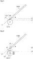
- FIGS. 9 and 10 are views illustrating an example in which a raw material is charged by using the raw material charging apparatus according to an embodiment of the present invention
- FIGS. 11 to 13 are views for explaining another example in which the raw material is charged by using the raw material charging apparatus according to an embodiment of the present invention
- FIGS. 14 to 17 are views illustrating a moving state of a lower charging chute according to a modified example of the present invention.
- first line L1 When a virtual line connecting centers of the plurality of fixed rolls 132 to each other is defined as a first line L1, the first line L1 may have the same curvature as that of a moving path formed in an upper portion of each of the fixed rolls 132. Also, a line extending from a center of a first fixed roll 132a, which is disposed at the lowermost end, of the fixed rolls 132 in a horizontal direction may be defined as a second line L2. Also, an angle that is defined by the first line L1 and the second line L2 may be a first angle a, and the first angle a may be an angle at which the mixed raw material moves on the fixed rolls 132. However, when the fixed roll 132 forms a moving path having a cycloid curve shape, an angle at which the mixed raw material moves may vary while the mixed raw material moves above the fixed roll 132.
- a line connecting a center of the first fixed roll 132a to a center of the movable roll 131 is defined as a third line L3, and a line extending from the center of the movable roll 131 in th horizontal direction is defined as a fourth line L4.
- an angle defined by the third line L3 and the fourth line L4 is defined as a second angle a0 that is an angle at which the mixed raw material breaks away from the charging chute 130.
- the movable roll 131 may move in the vertical direction according to an operation condition to change the second angle a0, thereby controlling a height and speed at which the mixed raw material breaks away from the charging chute 130.
- the movable roll 131 when the mixed raw material is charged at a maximum height H0, for example, 1500 mm at which the mixed raw material is charged into the sintering car 200, the movable roll 131 may be maintained at an initial height.
- the first angle a and the second angle a0 may be the same or similar to each other.
- the movable roll 131 when the mixed raw material is charged at a height H1, i.e., 900 mm, the movable roll 131 may move downward.
- the second angle a1 defined by the third line L3 and the fourth line L4 may further increase than the second angle a0 defined by the third line L3 and the fourth line L4 before the movable roll 131 moves.
- the mixed raw material may break away from the charging chute 130 to increase in moving distance up to the sintering car 200, and thus, pressure charging may occur by acceleration due to the increase of the moving distance.
- the movable roll 131 may move downward to reduce a distance between the movable roll 131 and the sintering car 200.
- the moving distance of the mixed raw material that breaks away from the charging chute 130 may be reduced, and also, the acceleration added to the moving speed of the mixed raw material by the reduced moving distance may be reduced to suppress the pressure charging within the sintering car 200 or prevent the pressure charging within the sintering car 200 from occurring.
- the mixed raw material may be charged into the sintering car 200 in a state in which the moving speed of the mixed raw material is reduced to prevent the pressure charging from occurring.
- air permeability within the raw material layer may be secured to improve sintering efficiency, thereby obtaining sintered ore having the uniform strength.
- the movable roll 131 and the first fixed roll 132a may be spaced apart from each other to form a space around the movable roll 131.
- the mixed raw material having a relatively small particle size e.g., fine coke may be discharged through the space so as to be charged into an upper layer portion of the raw material layer within the sintering car 200.
- the air permeability within the raw material layer may be improved to perform smooth sintering reaction, thereby improving quality and productivity of the sintered ore.
- Table 1 below shows a moving distance of the movable roll 131, i.e., a spaced distance between the first fixed roll 132a and the movable roll 131 according to the downwardly moving distance and the angle (the second angle) at which the mixed raw material breaks away from the movable roll 131.
- Table 1 shows an example in which the distance between the first fixed roll 132a and the movable roll 131 or a numerical value of the second angle may be variously changed.
- the moving distance of the movable roll 131 may increase to increase in distance between the first fixed roll 132a and the movable roll 131.
- the distance between the first fixed roll 132a and the movable roll 131 excessively increases, since vertical segregation of the raw material layer within the sintering car 200 may not be performed smoothly, it is preferable that the movable roll 131 does not excessively move. Also, it is seen that the more the moving distance of the movable roll 131 increases, the more the angle at which the mixed raw material breaks away from the movable roll 131 increases.
- the movable roll 131 properly moves to smoothly perform the charging pattern and the vertical segregation of the raw material layer within the sintering car 200.
- a rotation direction of the movable roll 131 together with the movement of the movable roll 131 according to a particle size, a moisture content, and a charging amount of the mixed raw material charged into the sintering car 200.
- the mixed raw material when the particle size of the mixed raw material is small, or the moisture content is high, the mixed raw material may be attached to the charging chute 130 or be reduced in moving speed due to friction thereof to cause light charging .
- the movable roll 131 may rotate in the moving direction of the mixed raw material to increase in charging speed of the mixed raw material, i.e., a speed at which the mixed raw material breaks away from the charging chute 130.
- the movable roll 131 may rotate at a speed quicker than the moving speed of the mixed raw material.
- pressure charging may occur when an amount of mixed raw material charged into the sintering car 200 is large.
- the movable roll 131 rotates in a direction opposite to the moving direction of the mixed raw material to reduce the charging speed of the mixed raw material.
- the rotation speed of the movable roll 131 is excessively high, the vertical segregation of the raw material layer within the sintering car 200 may not be formed.
- the movable roll 131 may rotate at a speed less than the moving speed of the mixed raw material.
- a charging pattern within the sintering car 200 may be constantly maintained by quickly responding to the operation condition without changing the overall structure of the charging chute 130.
- the occurrence of the pressure charging or the light charging within the sintering car 200 may be suppressed to constantly maintain the air permeability, thereby producing the high-quality sintered ore having the uniform strength.
- first line L1 When a virtual line connecting centers of the plurality of fixed rolls 132 to each other is defined as a first line L1, the first line L1 may have the same curvature as that of a moving path formed in an upper portion of each of the fixed rolls 132. Also, a line extending from a center of a first fixed roll 132a, which is disposed at the lowermost end, of the fixed rolls 132 in a horizontal direction may be defined as a second line L2. Also, an angle that is defined by the first line L1 and the second line L2 may be a first angle a, and the first angle a may be an angle at which the mixed raw material moves on the fixed rolls 132. However, when the fixed roll 132 forms a moving path having a cycloid curve shape, an angle at which the mixed raw material moves may vary while the mixed raw material moves above the fixed roll 132.
- a line connecting a center of the first fixed roll 132a to a center of the movable roll 131 is defined as a third line L3, and a line extending from the center of the movable roll 131 in th horizontal direction is defined as a fourth line L4.
- the third line L3 may be the moving path for the mixed raw material
- an angle defined by the third line L3 and the fourth line L4 may be a second angle a0 that is an angle at which the mixed raw material breaks away from the charging chute 130.
- a line extending perpendicular to the third line L3 that is the moving path of the mixed raw material is defined as a moving line L0.
- the movable roll 131 may move along the moving line L0 according to the operation condition to change the second angle a0 that is the angle at which the mixed raw material breaks away from the charging chute 130, thereby controlling a height and speed at which the mixed raw material breaks away from the charging chute 130.
- the movable roll 131 may be maintained at the reference height.
- the first angle a and the second angle a0 may be the same or similar to each other.
- the movable roll 131 may move downward along the moving line L0.
- an angle a1 defined by a third line L3' and the fourth line L4 may further increase than the angle a0 defined by the third line L3 and the fourth line L4 before the movable roll 131 moves.
- the mixed raw material may break away from the charging chute 130 to increase in moving distance up to the sintering car 200, and thus, pressure charging may occur by acceleration due to the increase of the moving distance.
- the movable roll 131 may diagonally move downward from the reference height to reduce a distance between the movable roll 131 and the sintering car 200.
- the moving distance of the mixed raw material that breaks away from the charging chute 130 may be reduced, and also, the acceleration added to the moving speed of the mixed raw material by the reduced moving distance may be reduced to suppress the pressure charging within the sintering car 200 or prevent the pressure charging within the sintering car 200 from occurring.
- the mixed raw material may be charged into the sintering car 200 in a state in which the moving speed of the mixed raw material is reduced to prevent the pressure charging from occurring.
- air permeability within the raw material layer may be secured to improve sintering efficiency, thereby obtaining sintered ore having the uniform strength.
- the movable roll 131 and th first fixed roll 132a may be spaced apart from each other, and thus, the mixed raw material having a relatively small particle size, e.g., fine coke may be discharged through the space so as to be charged into an upper layer portion of the raw material layer within the sintering car 200.
- the mixed raw material having the relatively small particle size is charged into the upper layer portion of the raw material layer within the sintering car 200, the air permeability within the raw material layer may be improved to perform smooth sintering reaction, thereby improving quality and productivity of the sintered ore.
- the movable roll 131 may move upward along the moving line L0.
- the center of the movable roll 131 moves upward, and as illustrated in FIG. 13(b) , an angle a1 defined by a third line L3' and the fourth line L4 may further decrease than the angle a0 defined by the third line L3 and the fourth line L4 before the movable roll 131 moves.
- the mixed raw material may break away from the charging chute 130 to decrease in moving distance up to the sintering car 200, and thus, light charging may occur.
- the movable roll 131 may diagonally move upward from the reference height to increase in distance between the movable roll 131 and the sintering car 200.
- the moving distance of the mixed raw material that breaks away from the charging chute 130 may increase, and also, the acceleration added to the moving speed of the mixed raw material by the increasing moving distance may increase to suppress the light charging within the sintering car 200 or prevent the light charging within the sintering car 200 from occurring.
- Table 2 below shows a moving distance of the movable roll 131, i.e., a spaced distance between the first fixed roll 132a and the movable roll 131 according to the diagonally moving distance and the angle (the second angle) at which the mixed raw material breaks away from the movable roll 131.
- Table 2 shows an example in which the distance between the first fixed roll 132a and the movable roll 131 or a numerical value of the second angle may be variously changed.
- the moving distance of the movable roll 131 may increase to increase in distance between the first fixed roll 132a and the movable roll 131.
- the distance between the first fixed roll 132a and the movable roll 131 excessively increases, since vertical segregation of the raw material layer within the sintering car 200 may not be performed smoothly, it is preferable that the movable roll 131 does not excessively move.
- the movable roll 131 may diagonally move to adjust the breakaway angle of the mixed raw material, thereby properly adjusting the charging pattern within the sintering car according to the fluctuation of the operation condition.
- the mixed raw material when the particle size of the mixed raw material is small, or the moisture content is high, the mixed raw material may be attached to the charging chute 130 or be reduced in moving speed due to friction thereof to cause light charging .
- the movable roll 131 may rotate in the moving direction of the mixed raw material to increase in charging speed of the mixed raw material, i.e., a speed at which the mixed raw material breaks away from the charging chute 130.
- the movable roll 131 may rotate at a speed quicker than the moving speed of the mixed raw material.
- pressure charging may occur when an amount of mixed raw material charged into the sintering car 200 is large.
- the movable roll 131 rotates in a direction opposite to the moving direction of the mixed raw material to reduce the charging speed of the mixed raw material.
- the rotation speed of the movable roll 131 is excessively high, the vertical segregation of the raw material layer within the sintering car 200 may not be formed.
- the movable roll 131 may rotate at a speed less than the moving speed of the mixed raw material.
- a charging pattern within the sintering car 200 may be constantly maintained by quickly responding to the operation condition without changing the overall structure of the charging chute 130.
- the occurrence of the pressure charging or the light charging within the sintering car 200 may be suppressed to constantly maintain the air permeability, thereby producing the high-quality sintered ore having the uniform strength.
- a line formed along a top surface of the upper charging chute 1320 is defined as a first line L1.
- the first line L1 may be the same as a moving path formed in an upper portion of the upper charging chute 1320.
- a line extending from an end of the upper charging chute 1320 adjacent to the lower charging chute 1310 in a horizontal direction is defined as a second line L2.
- an angle that is defined by the first line L1 and the second line L2 may be a first angle a
- the first angle a may be an angle at which the mixed raw material moves on the upper charging chute 1320.
- an angle at which the mixed raw material moves may vary while the mixed raw material moves above the upper charging chute 1320.
- a line connecting an end of the upper charging chute 1320 to an outer circumferential surface of the lower charging chute 1310 is defined as a third line L3, and a line extending from the third line L3 contacting the outer circumferential surface of the lower charging chute 1310 in a horizontal direction is defined as a fourth line L4.
- an angle defined by the third line L3 and the fourth line L4 is defined as a second angle a0.
- the third line L3 may indicate a direction in which the mixed raw material breaks away from the charging chute 130
- the second angle a0 may indicate an angle at which the mixed raw material breaks away from the charging chute 130.
- the lower charging chute 1320 may move in a direction crossing a width direction of the upper charging chute 1320 according to the operation condition to change the second angle a0 that is the angle at which the mixed raw material breaks away from the charging chute 130, thereby controlling a height and speed at which the mixed raw material breaks away from the charging chute 130.
- FIG. 15 illustrates an example in which the lower charging chute 1310 moves in the vertical direction, i.e., a state in which the lower charging chute 1310 moves downward in the initial state illustrated in FIG. 14 .
- the lower charging chute 1310 may descend in a direction that is vertical or perpendicular to the ground surface.
- the mixed raw material is charged at a maximum height at which the mixed raw material is capable of being charged into the sintering car, for example, a height of 1200 mm, the lower charging chute 1310 may be maintained in the initial state.
- the first angle a and the second angle a0 may be the same or similar to each other.
- the lower charging chute 1310 may descend.
- the lower charging chute 1310 may move along the line extending from a center of the lower charging chute 1310 in the direction perpendicular to a horizontal surface, e.g., the moving line L0.
- the second angle a1 defined by the third line L3 and the fourth line L4 may further increase than the second angle a0 defined by the third line L3 and the fourth line L4 before the lower charging chute 1310 moves.
- the mixed raw material may break away from the charging chute 130 to increase in moving distance up to the sintering car 200, and thus, pressure charging may occur by acceleration due to the increase of the moving distance.
- the lower charging chute 1310 may move downward to reduce a distance between the lower charging chute 1310 and the sintering car 200.
- the moving distance of the mixed raw material that breaks away from the charging chute 130 may be reduced, and also, the acceleration added to the moving speed of the mixed raw material by the reduced moving distance may be reduced to suppress the pressure charging within the sintering car 200 or prevent the pressure charging within the sintering car 200 from occurring.
- the mixed raw material may be charged into the sintering car 200 in a state in which the moving speed of the mixed raw material is reduced to prevent the pressure charging from occurring.
- FIG. 16 illustrates an example in which the lower charging chute 1310 moves in a direction perpendicular to the moving direction of the mixed raw material, i.e., in a diagonal direction.
- the lower charging chute 1310 may move downward to adjust the angle and height at which the mixed raw material breaks away from the charging chute 130.
- this example is different from the above-described example in that the direction in which the lower charging chute 1310 moves is a direction perpendicular to the moving direction of the mixed raw material.
- the moving line L0 of the lower charging chute 1310 may extend from the center of the lower charging chute 1310 in the moving direction of the mixed raw material in the upper charging chute 1320, i.e., the first lien L1.
- FIG. 17 illustrates an example in which the lower charging chute 1310 moves in the horizontal direction.
- the lower charging chute 1310 may move forward or backward in a longitudinal direction of the lower charging chute 1310, i.e., the direction perpendicular to the width direction of the upper charging chute 1320 in a state in which the height of the lower charging chute 1310 is maintained as it is.
- the moving line of the lower charging chute 1310 may extend from the center of the lower charging chute 1310 in the horizontal direction.
- the angle at which the mixed raw material breaks away from the charging chute 130 i.e., the second angle a1 may further increase than that in the initial state.
- the mixed raw material charged into the sintering car 200 decreases in height, for example, when the height of the mixed raw material is lower than that when the lower charging chute 1310 is maintained in the initial state, this may be applied.
- the angle at which the mixed raw material breaks away from the charging chute 130 i.e., the second angle a1 may further decrease than that in the initial state.
- the mixed raw material charged into the sintering car 200 increases in height, for example, when the moisture content within the mixed raw material is higher, or the particle size of the mixed raw material is larger than when the lower charging chute 1310 is maintained in the initial state, this may be applied.
- the lower charging chute 1310 may move according to the fluctuation of the operation condition to adjust the breakaway angle of the mixed raw material, thereby properly adjusting the charging pattern within the sintering car according to the fluctuation of the operation condition.
- the mixed raw material when the particle size of the mixed raw material is small, or the moisture content is high, the mixed raw material may be attached to the upper charging chute 1320 or be reduced in moving speed due to friction thereof to cause light charging .
- the lower charging chute 1310 may rotate in the moving direction of the mixed raw material to increase in charging speed of the mixed raw material, i.e., a speed at which the mixed raw material breaks away from the charging chute 130.
- the lower charging chute 1310 may rotate at a speed quicker than the moving speed of the mixed raw material.
- pressure charging may occur when an amount of mixed raw material charged into the sintering car 200 is large.
- the lower charging chute 1310 rotates in a direction opposite to the moving direction of the mixed raw material to reduce the charging speed of the mixed raw material.
- the rotation speed of the lower charging chute1310 is excessively high, the vertical segregation of the raw material layer within the sintering car 200 may not be formed.
- the lower charging chute 1310 may rotate at a speed less than the moving speed of the mixed raw material.
- a charging pattern within the sintering car 200 may be constantly maintained by quickly responding to the operation condition without changing the overall structure of the charging chute 130.
- the occurrence of the pressure charging or the light charging within the sintering car 200 may be suppressed to constantly maintain the air permeability, thereby producing the high-quality sintered ore having the uniform strength.
- the air permeability within the raw material layer in the sintering process may be constantly maintained to produce the sintered ore having the uniform strength, thereby improving the process efficiency and the productivity.
Landscapes
- Engineering & Computer Science (AREA)
- Mechanical Engineering (AREA)
- General Engineering & Computer Science (AREA)
- Chemical & Material Sciences (AREA)
- Life Sciences & Earth Sciences (AREA)
- General Life Sciences & Earth Sciences (AREA)
- Geochemistry & Mineralogy (AREA)
- Geology (AREA)
- Manufacturing & Machinery (AREA)
- Environmental & Geological Engineering (AREA)
- Materials Engineering (AREA)
- Metallurgy (AREA)
- Organic Chemistry (AREA)
- Manufacture And Refinement Of Metals (AREA)
- Furnace Charging Or Discharging (AREA)
Abstract
Description
- The present invention relates to a raw material charging apparatus and a charging method thereof, and more particularly, to a raw material charging apparatus and method, which are capable of improving quality and productivity of sintered ore by rapidly responding to fluctuation in operation.
- In general, in a process of producing sintered ore, fine iron ore, subsidiary raw materials, and fuels (fine coke, anthracite, or the like) are put into a drum mixer to be mixed and humidified so that the sintering mixed raw material that is pseudo-granulated is charged into a sintering car.
- The sintering mixed raw material is charged into the sintering car by using a charging chute constituted by an inclined plate and a plurality of rolls or rods. The charging chute generates grain segregation so that large and heavy particles of the sintering mixed raw material are charged into a lower layer of the sintering car, and small and light particles are charged in the upper layer to induce segregation charging so that air permeability is good during the sintering.
- In the process of producing the sintered ore, when the fluctuation in operation such as a variation in height (layer thickness) of the raw material layer or a change in moisture content or particle size in the sintering mixed raw material occurs, fluctuation in charging pattern is inevitable. For example, in the case in which it is necessary to reduce the layer thickness rather than the normal operation, since pressure charging occurs in a state in which a height of the lowermost end of the charging chute is fixed, the height of the lowermost end of the charging chute may be lowered, or an inclination of the charging chute may be reduced to reduce a moving speed of the sintering mixed raw material. Also, in a case in which a relatively large amount of moisture is contained in the sintering mixed raw material, the fine raw material of the sintering mixed raw material is attached to the charging chute to reduce the moving speed of the sintering mixed raw material moving along the charging chute, it is necessary to increase in inclination of the charging chute so as to maintain the moving speed of the sintering mixed raw material. Also, in a case in which it is necessary to increase in layer thickness rather than the normal operation, a lower end of the charging chute may contact the raw material layer to press the a surface layer portion, thereby reducing the air permeability during the sintering.
- However, when the height or inclination of the charging chute is changed, there is a problem in that it is difficult to quickly respond to the fluctuation in operation because a relationship between peripheral facilities have to be considered.
- The present invention provides a raw material charging apparatus and a charging method thereof, which are capable of quickly responding to fluctuation in operation.
- The present invention provides a raw material charging apparatus and a charging method thereof, which are capable of improving air permeability of a raw material layer to improve quality and productivity of sintered ore.
- A raw material charging apparatus according to an embodiment of the present invention may include a charging chute disposed between a raw material feeding part and a container to charge a raw material into the container, wherein the charging chute may include a movable roll, which is movable in a direction crossing a width direction of the charging chute, in at least a portion thereof.
- The charging chute may include a plurality of fixed rolls that are disposed parallel to each other to form a moving path for the raw material, and the movable roll may be disposed below the fixed rolls from which the raw material breaks away into the container.
- The charging chute may include an upper charging chute having an area and a plate shape to form the moving path for the raw material, and the movable roll may be disposed on a lower portion of the upper charging chute from which the raw material breaks away into the container.
- The movable roll may be disposed at the lowermost end in a direction in which the raw material moves in the charging chute.
- At least a portion of the moving path may have a linear or curved cross-sectional shape.
- At least a portion of the moving path may have a cycloid curved cross-sectional shape.
- The raw material charging apparatus may further include an elevation unit that allows the movable roll to move.
- The elevation unit may include one of a cylinder, a screw shaft, and a hydraulic jack.
- The raw material charging apparatus may further include a driving unit that allows the movable roll to rotate.
- The movable roll may be movable in a vertical direction.
- The movable may be movable in a vertical direction or a direction perpendicular to the moving direction of the raw material that moves along the charging chute.
- The movable roll may move forward and backward in the direction crossing the width direction of the charging chute.
- A raw material charging method for charging a raw material into a container by using a charging chute forming a moving path for the raw material according to an embodiment of the present invention may include: allowing a movable roll disposed on a lower portion of the charging chute, from which the raw material breaks away into the container, to move in a direction crossing a width direction of the charging chute; and feeding the raw material into the charging chute to charge the raw material into the container.
- The allowing of the movable roll to move in the direction crossing the width direction of the charging chute may include allow the movable roll to move according to at least one of a particle size of the raw material, a moisture content of the raw material, or a charging amount of the raw material.
- The movable roll may move to adjust at least one of a speed or height at which the raw material breaks away from the charging chute.
- The movable roll may move to form a space around the movable roll.
- While the raw material is charged into the container, a portion of the raw material may be discharged into the space to charge the raw material into an upper layer portion of a raw material layer formed in the container.
- While the raw material is charged into the container, the movable roll may rotate.
- According to the embodiment of the present invention, it may be possible to control the charging pattern of the sintering mixed raw material in response to the fluctuation of the operation condition. That is, the movable roll may be provided in the lower portion of the charging chute, and the movable roll may move according to the operation condition fluctuation to control the breakaway angle and speed of the mixed raw material charged into the sintering car. Since the charging pattern is quickly controlled according to the operation fluctuation, the charging fluctuation of the raw material layer within the sintering car may be minimized. Thus, the sintered ore having the predetermined strength while constantly maintaining the air permeability within the raw material layer during the sintering may be manufactured to improve the process efficiency and the productivity.
-
-
FIG. 1 is a schematic view of a raw material charging apparatus according to an embodiment of the present invention. -
FIGS. 2 to 5 are perspective and cross-sectional views of a charging chute constituting the raw material charging apparatus according to an embodiment of the present invention. -
FIG. 6 is a schematic view illustrating an example of an elevation unit for driving a movable roll. -
FIG. 7 is a schematic view of a raw material charging apparatus according to a modified example of the present invention. -
FIG. 8 is a perspective view of a charging chute constituting the raw material charging apparatus according to an embodiment of the present invention. -
FIGS. 9 and10 are views illustrating an example in which a raw material is charged by using the raw material charging apparatus according to an embodiment of the present invention. -
FIGS. 11 to 13 are views for explaining another example in which the raw material is charged by using the raw material charging apparatus according to an embodiment of the present invention. -
FIGS. 14 to 17 are views illustrating a moving state of a lower charging chute according to a modified example of the present invention. - Hereinafter, specific embodiments will be described in detail with reference to the accompanying drawings. The present invention may, however, be embodied in different forms and should not be construed as limited to the embodiments set forth herein. Rather, these embodiments are provided so that the present invention will be thorough and complete, and will fully convey the scope of the present invention to those skilled in the art.
-
FIG. 1 is a schematic view of a raw material charging apparatus according to an embodiment of the present invention. - First, a raw material charging apparatus according to an embodiment of the present invention will be described with reference to the accompanying drawings.
- Referring to
FIG. 1 , a raw material charging apparatus may include a raw material feeding part comprising araw material hopper 100 and adrum feeder 120 and acharging chute 130. - The raw material hopper 100 feeds mixed raw materials 1 such as fine iron ore, subsidiary raw materials, and fine coke to the
drum feeder 120 via ahopper gate 110, and thedrum feeder 120 mixes the mixed raw materials 1 fed therein while rotating to dispense the mixed raw material 1 to thecharging chute 130. - The
charging chute 130 is provided between the raw material hopper 1 and a sinteringcar 200 to charge the mixed raw material 1 into the sinteringcar 200. In thecharging chute 130, a plurality of rolls are disposed parallel to each other to form a moving path, through which the mixed raw material moves, in an upper portion thereof. Here, thecharging chute 130 may have the moving path that is formed in an inclined surface or curved surface shape having a predetermined area. Here, when thecharging chute 130 is formed in the curved surface shape having the predetermined area, thecharging chute 130 may have a transverse sectional shape formed in a cycloid curve shape. Due to the above-described configuration, thecharging chute 130 may serve to promote vertical segregation so that the mixed raw material having a relatively large particle size is charged into a lower portion of thesintering car 200, and the mixed raw material having a relatively small particle size is charged into an upper portion of thesintering car 200. - When the mixed raw material 1 is charged into the sintering
car 200 by using the raw material charging apparatus to form a raw material layer, a surface layer portion of the raw material layer may be planarized on asurface smoothing plate 140 provided at a front side with respect to a moving direction of the sinteringcar 200. Sequentially, the surface layer portion is ignited in aigniting burner 150 provided in front of thesurface smoothing plate 140, and while the sinteringcar 200 moves along a sintering section, the fuel material of the mixed raw material within thesintering car 200, for example, the fin coke may be burned by suction force of a wind box to manufacture sintered ore. - The
charging chute 130 may include amovable roll 131 that is movable in a direction crossing a width direction of thecharging chute 130. Here, in thecharging chute 130, the plurality of rolls are disposed parallel to each other to form a moving path for the mixed raw material. Themovable roll 131 may be provided in the lower portion of thecharging chute 130, i.e., the lower portion from which the mixed raw material brakes away so as to be movable in the direction crossing the width direction of thecharging chute 130, e.g., in at least one direction of a vertical direction and a diagonal direction. Here, the diagonal direction may be a direction crossing the moving direction of the raw material, e.g., a direction perpendicular to the moving direction. That is, in the chargingchute 130, at least a portion of the plurality of rolls may be a fixedroll 132 of which an installation position is fixed to maintain the moving path for the mixed raw material at a constant angle, and at least a portion may be themovable roll 131 of which an installation position is variable. Here, the fixedroll 132 may be provided from the upper portion of the chargingchute 130 in a longitudinal direction of the chargingchute 130, and themovable roll 131 may be provided from the lower portion of the chargingchute 130 in the longitudinal direction of the chargingchute 130. For example, themovable roll 131 may be provided at the lowermost end of the chargingchute 130, at which the mixed raw material breaks away from the moving path formed in the chargingchute 130. Here, although the structure in which themovable roll 131 is provided at the lowermost end of the charging chute is described, about two or three movable rolls in addition to the roll disposed at the lowermost end may be provided from the lower portion of the chargingchute 130. -
FIGS. 2 to 5 are perspective and cross-sectional views of the charging chute constituting the raw material charging apparatus according to an embodiment of the present invention, andFIG. 6 is a schematic view illustrating an example of an elevation unit for driving the movable roll. - First, referring to
FIGS. 2 and3 , the plurality of rolls of the fixedroll 132 may be disposed parallel to each other to form the moving path through which the mixed raw material moves. Here, the moving path for the mixed raw material, which is formed by the fixedroll 132, may form a moving path having a cycloid curve shape. The fixedroll 132 may be rotatably provided to rotate in a moving direction of the mixed raw material and in a direction opposite to the moving direction. This is done for controlling the rotation direction according to a charging amount of the mixed raw material, a moisture content of the mixed raw material, and a particle size of the mixed raw material. - The
movable roll 131 may be provided at the lowermost end of the chargingchute 130, for example, may be provided to be movable in an upward/downward direction, e.g., in a vertical direction. Here, themovable roll 131 may be provided to be rotatable at a position adjacent to the lowermostfixed roll 132 of the fixed rolls 132, for example, a firstfixed roll 132a. Themovable roll 131 may vertically move according to a change in layer thickness, the particle size of the mixed raw material, or the moisture content of the mixed raw material to adjust a moving distance or moving speed of the mixed raw material discharged to thesintering car 200. - Also, referring to
FIGS. 4 and5 , themovable roll 131 may be provided at the lowermost end of the chargingchute 130 and also be provided to be movable in the direction crossing the moving direction of the mixed raw material, e.g., the direction perpendicular to the moving direction. Here, themovable roll 131 may be provided to be diagonally movable in a direction that is inclined downward with respect to the moving direction of the mixed raw material. Also, themovable roll 131 may be provided to be rotatable at a position adjacent to the lowermostfixed roll 132 of the fixed rolls 132, for example, the firstfixed roll 132a. Themovable roll 131 may diagonally move in the direction perpendicular to the moving direction of the mixed raw material according to the change in layer thickness, the particle size of the mixed raw material, or the moisture content of the mixed raw material to adjust the moving distance or moving speed of the mixed raw material discharged to thesintering car 200. - As described above, an
elevation unit 300 supporting themovable roll 131 to allow themovable roll 131 to move in the vertical direction or in the direction crossing the moving direction of the mixed raw material and a driving unit providing rotation force to allow themovable roll 131 to rotate may be provided. - Various constituents such as a cylinder, a screw shaft, a hydraulic jack, and the like may be used as the
elevation unit 300. In this embodiment, an example in which the screw shaft is used as theelevation unit 300 will be described. - Referring to
FIG. 6 , the elevation unit may include asupport frame 310 provided on each of both sides of themovable roll 131 and aconnection member 320 connecting themovable roll 131 to thesupport frame 310 so that themovable roll 131 is movable in the vertical direction. Here, acontact member 330 such as a bearing may be provided between themovable roll 131 and theconnection member 320 so that themovable roll 131 is rotatably connected to theconnection member 320. - The
support frame 310 may be disposed in a longitudinal direction of themovable roll 131, for example, in a direction crossing a width direction of the chargingchute 130. That is, since themovable roll 131 is provided to be movable in the vertical direction or the direction crossing the moving direction of the raw material, thesupport frame 310 may be provided to extend in the moving direction of themovable roll 131. For example, as illustrated inFIG. 2 , when themovable roll 131 moves in the vertical direction, thesupport frame 310 may be provided to extend in the vertical direction. Also, as illustrated inFIG. 4 , when themovable roll 131 moves in the direction crossing the moving direction of the raw material, i.e., in the diagonal direction, thesupport frame 310 may be disposed in the longitudinal direction of themovable roll 131, for example, in the direction crossing the width direction of the chargingchute 130. More particularly, a lower portion of thesupport frame 310 may be disposed to be inclined downward in the moving direction of the mixed raw material. Thus, themovable roll 131 may ascend and descend in the longitudinal direction of thesupport frame 310 to move in the diagonal direction. - A screw thread may be formed on an outer circumferential surface of the
support frame 310. Thesupport frame 310 may be rotatably provided. Agrip part 314 may be provided on thesupport frame 310 so that thesupport frame 310 directly rotates by a worker. When thesupport frame 310 automatically rotates, a separate power part (not shown) may be connected. In the latter case, a sensor (not shown) for measuring a height of themovable roll 131 and a control part (not shown) for controlling the power part by using the result measured by the sensor may be provided so that thesupport frame 310 rotates to automatically adjust the height of themovable roll 131. - Also, the
connection member 320 may have a ring shape surrounding at least a portion of thesupport frame 310. A screw thread may be formed on an inner circumferential surface of theconnection member 320 and thus be engaged with a screw thread formed on an outer circumferential surface of thesupport frame 310. Due to this configuration, when thesupport frame 310 rotates, theconnection member 320 may move in the longitudinal direction of thesupport frame 310 to allow themovable roll 131 to move in the vertical direction or diagonally move in the direction crossing the moving direction of the raw material. - The
contact member 330 may be provided between themovable roll 131 and theconnection member 320 so that the rotation force is not transmitted to the connection member even though themovable roll 131 rotates. As described above, the bearing may be used as thecontact member 330. One side of thecontact member 330, which is connected to theconnection member 320, may become a fixed side, and the other side of thecontact member 330, which is connected to themovable roll 131, may become a free side. - The driving unit may include a
driver 350 providing rotation force and amotion transmitting member 340 transmitting the rotation force provided from thedriver 350 to themovable roll 131. Here, themotion transmitting member 340 may be provided between themovable roll 131 and thecontact member 330 and be provided as a gear box including various gears. - Due to this configuration, the raw material charging apparatus may adjust a position, e.g., a height of the
movable roll 131 without adjusting a position, angle, and height of the chargingchute 130 to quickly respond to the fluctuation of the operation condition. That is, when the height of themovable roll 131 is changed, an angle of the lowermost end of the chargingchute 130, which has the greatest influence when charging the mixed raw material into thesintering car 200, may be freely adjusted to quickly response the fluctuation of the operation condition. - For example, when the
movable roll 131 is disposed to be movable in the vertical direction, themovable roll 131 may have a maximum height of the raw material layer that is capable of being changed into thesintering car 200, for example, a height corresponding to 1500 mm (layer thickness) as an initial height. The initial height herein means a maximum height when themovable roll 131 moves in the vertical direction, and themovable roll 131 may only move downward from the initial height. This is done because, when themovable roll 131 ascends, themovable roll 131 may act as an obstacle with respect to the transferring of the mixed raw material to affect the movement of the mixed raw material. - Thus, when the fluctuation of the layer thickness occurs, for example, the height of the raw material layer charged into the
sintering car 200 is less than 1500 mm, themovable roll 131 may move downward according to a difference in height to adjust a height or angle, at which the mixed raw material breaks away from the chargingchute 130, thereby preventing pressure charging or light charging within thesintering car 200 from occurring. The detailed contents thereof will be described later. - Also, when the
movable roll 131 is disposed to be movable in the direction crossing the moving direction of the raw material, themovable roll 131 may have a reference height of the raw material layer to be charged into thesintering car 200 when common sintered ore is produced, for example, a height corresponding to 1200 mm (layer thickness) as a reference height. The reference height herein may mean a height corresponding to the height of the raw material layer charged into thesintering car 200 when the sintered ore is produced, i.e., a height at which an angle similar to the angle of themovable roll 131 with respect to the moving path formed by the fixedroll 132. Here, themovable roll 131 may be movable upward and downward from the reference height. - Thus, when the fluctuation of the layer thickness occurs, for example, the height of the raw material layer charged into the
sintering car 200 is greater or less than 1200 mm, themovable roll 131 may diagonally move according to a difference in height to ascend or descend and thereby to adjust a height or angle, at which the mixed raw material breaks away from the chargingchute 130, thereby preventing the pressure charging or the light charging within thesintering car 200 from occurring. The detailed contents thereof will be described later. - Although the case in which the charging chute is provided as the plurality of rolls has been described above, the charging chute may include an inclined plate having a predetermined area.
-
FIG. 7 is a schematic view of a raw material charging apparatus according to a modified example of the present invention, andFIG. 8 is a perspective view of a charging chute constituting the raw material charging apparatus according to an embodiment of the present invention. - Referring to
FIG. 7 , a chargingchute 1300 is provided between theraw material hopper 100 and asintering car 200 to charge a mixed raw material 1 into thesintering car 200. The chargingchute 1300 may include a movable roll that is movable in a direction crossing a width direction of the chargingchute 1300. Here, the chargingchute 1300 may include an upper charging chute 1230 extending in one direction and having a plate shape at an upper portion thereof to form a moving path through which the mixed raw material 1 moves and alower charging chute 1310 provided to be movable in a direction crossing a width direction of theupper charging chute 1320 and having a roll shape at a lower portion thereof, for example, a movable roll. Here, theupper charging chute 1320 may be provided to be inclined downward toward thesintering car 200, and the moving path formed in theupper charging chute 1320 may be formed to have a linear or curved transverse cross-sectional shape. Also, here, when theupper charging chute 1320 has the moving path with the curved cross-sectional shape, the moving path may have a cycloid curve shape. - Also, the
lower charging chute 1310 may be disposed along the width direction of theupper charging chute 1320 below theupper charging chute 1320 and provided to be movable in the direction crossing the width direction of theupper charging chute 1320. Thelower charging chute 1310 may be rotatably provided to rotate in the moving direction of the mixed raw material and in a direction opposite to the moving direction. Thus, thelower charging chute 1310 may adjust a breakaway speed or angle at which the raw material is charged into thesintering car 200. - Referring to
FIG. 8 , the chargingchute 1300 may include theupper charging chute 1320 having the plate shape and thelower charging chute 1310 having the roll shape and disposed along the width direction of theupper charging chute 1320 below theupper charging chute 1320. Here, thelower charging chute 1310 may be provided to be movable in the direction crossing the width direction of theupper charging chute 1320 below theupper charging chute 1320. Also, thelower charging chute 1310 may be rotatably provided. - The
upper charging chute 1320 may form a substantial moving path through which the raw material fed from theraw material hopper 100 moves, and thelower charging chute 1310 may adjust an angle and height at which the mixed raw material 1 breaks away from the chargingchute 1300 when the mixed raw material 1 moving along theupper charging chute 1320 is charged into the chargingcar 200. That is, theupper charging chute 1320 may be fixed in installation position to maintain the path, through which the mixed raw material moves, at a constant angle, and thelower charging chute 1310 may be changeable in position to adjust the angle and height, at which the mixed raw material breaks away from the chargingchute 1300 just before the mixed raw material 1 is charged into thesintering car 200. Here, although thelower charging chute 1310 is provided as one roll, thelower charging chute 1310 may include a plurality of rolls as necessary. - The
upper charging chute 1320 may form the moving path through which the mixed raw material moves so that the mixed raw material discharged from adrum feeder 120 is maintained in a state in which particles of the mixed raw material are granulated and classified. - The
lower charging chute 1310 may be provided to be movable in the direction crossing the width direction of theupper charging chute 1320. Here, the direction crossing the width direction of theupper charging chute 1320 may mean at least one direction of a vertical direction, a diagonal direction, and a horizontal direction. - As described above, the
lower charging chute 1310 may move in the direction crossing the width direction of theupper charging chute 1320 according to an operation condition, for example, a change in layer thickness, a particle size of the mixed raw material, or a moisture content of the mixed raw material to adjust at least one of the height and angle at which the mixed raw material breaks away from the chargingchute 1300 and thereby to adjust a moving distance or moving speed of the mixed raw material discharged to thesintering car 200, thereby controlling a charging pattern of the mixed raw material. - An
elevation unit 300 supporting thelower charging chute 1310 to allow thelower charging chute 1310 to move and a driving unit providing rotation force to allow thelower charging chute 1310 to rotate may be provided. - The
elevation unit 300 may have a structure that is substantially similar to that of the elevation unit according to the foregoing embodiment and may change an arranged shape of asupport frame 310 according to the moving direction of thelower charging chute 1310. That is, thesupport frame 310 may be disposed in one direction of the vertical direction, the diagonal direction, and the horizontal direction according to the moving direction of thelower charging chute 1310 and thus used as the moving path of thelower charging chute 1310. When thelower charging chute 1310 move in the vertical direction, thesupport frame 310 may be disposed to extend in a direction perpendicular to a horizontal surface. Also, when thelower charging chute 1310 moves in the diagonal direction, i.e., in the direction perpendicular to the moving direction of the mixed raw material, a lower portion of thesupport frame 310 may be disposed to be inclined downward. Also, both sides of the support frame may be disposed to be inclined downward in the moving direction of the mixed raw material. Also, when thelower charging chute 1310 moves in the horizontal direction, thesupport frame 310 may be disposed parallel to the horizontal surface or the ground surface. - Hereinafter, a method for charging a mixed raw material into a sintering car by using the raw material charging apparatus according to the present invention will be described.
-
FIGS. 9 and10 are views illustrating an example in which a raw material is charged by using the raw material charging apparatus according to an embodiment of the present invention,FIGS. 11 to 13 are views for explaining another example in which the raw material is charged by using the raw material charging apparatus according to an embodiment of the present invention, andFIGS. 14 to 17 are views illustrating a moving state of a lower charging chute according to a modified example of the present invention. - First, an example in which a
movable roll 131 moves in a vertical direction will be described with reference toFIGS. 9 and10 . - An arrangement relationship between fixed
rolls 132 and themovable roll 131, which constitute a chargingchute 130, will be described. - When a virtual line connecting centers of the plurality of fixed
rolls 132 to each other is defined as a first line L1, the first line L1 may have the same curvature as that of a moving path formed in an upper portion of each of the fixed rolls 132. Also, a line extending from a center of a firstfixed roll 132a, which is disposed at the lowermost end, of the fixed rolls 132 in a horizontal direction may be defined as a second line L2. Also, an angle that is defined by the first line L1 and the second line L2 may be a first angle a, and the first angle a may be an angle at which the mixed raw material moves on the fixed rolls 132. However, when the fixedroll 132 forms a moving path having a cycloid curve shape, an angle at which the mixed raw material moves may vary while the mixed raw material moves above the fixedroll 132. - Also, a line connecting a center of the first
fixed roll 132a to a center of themovable roll 131 is defined as a third line L3, and a line extending from the center of themovable roll 131 in th horizontal direction is defined as a fourth line L4. Here, an angle defined by the third line L3 and the fourth line L4 is defined as a second angle a0 that is an angle at which the mixed raw material breaks away from the chargingchute 130. - According to the present invention, the
movable roll 131 may move in the vertical direction according to an operation condition to change the second angle a0, thereby controlling a height and speed at which the mixed raw material breaks away from the chargingchute 130. - For example, as illustrated in
FIGS. 9(a) and 9(b) , when the mixed raw material is charged at a maximum height H0, for example, 1500 mm at which the mixed raw material is charged into thesintering car 200, themovable roll 131 may be maintained at an initial height. Here, the first angle a and the second angle a0 may be the same or similar to each other. - On the other hand, as illustrated in
FIG. 10(a) , when the mixed raw material is charged at a height H1, i.e., 900 mm, themovable roll 131 may move downward. Here, since the center of themovable roll 131 moves downward, as illustrated inFIG. 10(b) , the second angle a1 defined by the third line L3 and the fourth line L4 may further increase than the second angle a0 defined by the third line L3 and the fourth line L4 before themovable roll 131 moves. - When a raw material layer formed in the
sintering car 200 decreases in height, the mixed raw material may break away from the chargingchute 130 to increase in moving distance up to thesintering car 200, and thus, pressure charging may occur by acceleration due to the increase of the moving distance. Thus, themovable roll 131 may move downward to reduce a distance between themovable roll 131 and thesintering car 200. When the distance between themovable roll 131 and thesintering car 200 is reduced, the moving distance of the mixed raw material that breaks away from the chargingchute 130 may be reduced, and also, the acceleration added to the moving speed of the mixed raw material by the reduced moving distance may be reduced to suppress the pressure charging within thesintering car 200 or prevent the pressure charging within thesintering car 200 from occurring. Also, since the angle at which the mixed raw material breaks away from the chargingchute 130, i.e., the angle a1 defined by the third line L3 and the fourth line L4 increases to change the moving path of the mixed raw material, when the mixed raw material breaks away from themovable roll 131 because it is difficult to maintain the moving speed of the mixed raw material on the fixedroll 132, the mixed raw material may be charged into thesintering car 200 in a state in which the moving speed of the mixed raw material is reduced to prevent the pressure charging from occurring. - As described above, when the pressure charging within the
sintering car 200 is suppressed or prevented, air permeability within the raw material layer may be secured to improve sintering efficiency, thereby obtaining sintered ore having the uniform strength. - When the
movable roll 131 descends, themovable roll 131 and the firstfixed roll 132a may be spaced apart from each other to form a space around themovable roll 131. Thus, the mixed raw material having a relatively small particle size, e.g., fine coke may be discharged through the space so as to be charged into an upper layer portion of the raw material layer within thesintering car 200. As described above, when the mixed raw material having the relatively small particle size is charged into the upper layer portion of the raw material layer within thesintering car 200, the air permeability within the raw material layer may be improved to perform smooth sintering reaction, thereby improving quality and productivity of the sintered ore. - Table 1 below shows a moving distance of the
movable roll 131, i.e., a spaced distance between the firstfixed roll 132a and themovable roll 131 according to the downwardly moving distance and the angle (the second angle) at which the mixed raw material breaks away from themovable roll 131. Table 1 shows an example in which the distance between the firstfixed roll 132a and themovable roll 131 or a numerical value of the second angle may be variously changed.[Table 1] Vertical moving distance (hmm) Distance between first fixed roll and movable (pmm) Second angle (a1°) 0 4.12 41.4 10 8.82 44.1 20 13.34 46.55 30 17.64 48.8 40 21.73 50.9 50 25.59 52.78 - Referring to Table 1 above, when the
movable roll 131 moves downward, the moving distance of themovable roll 131 may increase to increase in distance between the firstfixed roll 132a and themovable roll 131. Here, when the distance between the firstfixed roll 132a and themovable roll 131 excessively increases, since vertical segregation of the raw material layer within thesintering car 200 may not be performed smoothly, it is preferable that themovable roll 131 does not excessively move. Also, it is seen that the more the moving distance of themovable roll 131 increases, the more the angle at which the mixed raw material breaks away from themovable roll 131 increases. Here, when the breakaway angle of the mixed raw material excessively increases, the excessive breakaway angle may adversely affect the vertical segregation of the raw material layer within thesintering car 200. Thus, it is preferable that themovable roll 131 properly moves to smoothly perform the charging pattern and the vertical segregation of the raw material layer within thesintering car 200. - Also, it may be possible to control a rotation direction of the
movable roll 131 together with the movement of themovable roll 131 according to a particle size, a moisture content, and a charging amount of the mixed raw material charged into thesintering car 200. - For example, when the particle size of the mixed raw material is small, or the moisture content is high, the mixed raw material may be attached to the charging
chute 130 or be reduced in moving speed due to friction thereof to cause light charging . In this case, themovable roll 131 may rotate in the moving direction of the mixed raw material to increase in charging speed of the mixed raw material, i.e., a speed at which the mixed raw material breaks away from the chargingchute 130. Here, themovable roll 131 may rotate at a speed quicker than the moving speed of the mixed raw material. On the other hand, when an amount of mixed raw material charged into thesintering car 200 is large, pressure charging may occur. In this case, it is necessary that themovable roll 131 rotates in a direction opposite to the moving direction of the mixed raw material to reduce the charging speed of the mixed raw material. Here, when the rotation speed of themovable roll 131 is excessively high, the vertical segregation of the raw material layer within thesintering car 200 may not be formed. Thus, themovable roll 131 may rotate at a speed less than the moving speed of the mixed raw material. - In this method, when the mixed raw material is charged into the
sintering car 200, a charging pattern within thesintering car 200 may be constantly maintained by quickly responding to the operation condition without changing the overall structure of the chargingchute 130. Thus, even though the operation condition is fluctuated, the occurrence of the pressure charging or the light charging within thesintering car 200 may be suppressed to constantly maintain the air permeability, thereby producing the high-quality sintered ore having the uniform strength. - Next, an example in which the
movable roll 131 moves in the direction crossing the moving direction of the raw material will be described with reference toFIGS. 11 to 13 . - First, an arrangement relationship between the
fixed roll 132 and themovable roll 131, which constitute the chargingchute 130, will be described with reference toFIGS. 11 to 13 . - When a virtual line connecting centers of the plurality of fixed
rolls 132 to each other is defined as a first line L1, the first line L1 may have the same curvature as that of a moving path formed in an upper portion of each of the fixed rolls 132. Also, a line extending from a center of a firstfixed roll 132a, which is disposed at the lowermost end, of the fixed rolls 132 in a horizontal direction may be defined as a second line L2. Also, an angle that is defined by the first line L1 and the second line L2 may be a first angle a, and the first angle a may be an angle at which the mixed raw material moves on the fixed rolls 132. However, when the fixedroll 132 forms a moving path having a cycloid curve shape, an angle at which the mixed raw material moves may vary while the mixed raw material moves above the fixedroll 132. - Also, a line connecting a center of the first
fixed roll 132a to a center of themovable roll 131 is defined as a third line L3, and a line extending from the center of themovable roll 131 in th horizontal direction is defined as a fourth line L4. Here, when themovable roll 131 is disposed at the reference height, the third line L3 may be the moving path for the mixed raw material, and an angle defined by the third line L3 and the fourth line L4 may be a second angle a0 that is an angle at which the mixed raw material breaks away from the chargingchute 130. - Also, when the
movable roll 131 is disposed at the reference height, a line extending perpendicular to the third line L3 that is the moving path of the mixed raw material is defined as a moving line L0. - According to the present invention, the
movable roll 131 may move along the moving line L0 according to the operation condition to change the second angle a0 that is the angle at which the mixed raw material breaks away from the chargingchute 130, thereby controlling a height and speed at which the mixed raw material breaks away from the chargingchute 130. - For example, as illustrated in
FIGS. 11(a) and 11(b) , when the height of the mixed raw material charged into thesintering car 200 under the common operation condition, e.g., a first height H0 is 1200 mm, themovable roll 131 may be maintained at the reference height. Here, the first angle a and the second angle a0 may be the same or similar to each other. - On the other hand, as illustrated in
FIG. 12(a) , when the mixed raw material is charged at a second height H1 that is less than the first height H0, i.e., 900 mm, themovable roll 131 may move downward along the moving line L0. Here, since the center of themovable roll 131 moves downward, as illustrated inFIG. 12(b) , an angle a1 defined by a third line L3' and the fourth line L4 may further increase than the angle a0 defined by the third line L3 and the fourth line L4 before themovable roll 131 moves. - When a raw material layer formed in the
sintering car 200 decreases in height, the mixed raw material may break away from the chargingchute 130 to increase in moving distance up to thesintering car 200, and thus, pressure charging may occur by acceleration due to the increase of the moving distance. Thus, themovable roll 131 may diagonally move downward from the reference height to reduce a distance between themovable roll 131 and thesintering car 200. When the distance between themovable roll 131 and thesintering car 200 is reduced, the moving distance of the mixed raw material that breaks away from the chargingchute 130 may be reduced, and also, the acceleration added to the moving speed of the mixed raw material by the reduced moving distance may be reduced to suppress the pressure charging within thesintering car 200 or prevent the pressure charging within thesintering car 200 from occurring. Also, since the angle at which the mixed raw material breaks away from the chargingchute 130, i.e., the angle a1 defined by the third line L3' and the fourth line L4 increases to change the moving path of the mixed raw material, when the mixed raw material breaks away from themovable roll 131 because it is difficult to maintain the moving speed of the mixed raw material on the fixedroll 132, the mixed raw material may be charged into thesintering car 200 in a state in which the moving speed of the mixed raw material is reduced to prevent the pressure charging from occurring. - As described above, when the pressure charging within the
sintering car 200 is suppressed or prevented, air permeability within the raw material layer may be secured to improve sintering efficiency, thereby obtaining sintered ore having the uniform strength. - When the
movable roll 131 moves, themovable roll 131 and th first fixedroll 132a may be spaced apart from each other, and thus, the mixed raw material having a relatively small particle size, e.g., fine coke may be discharged through the space so as to be charged into an upper layer portion of the raw material layer within thesintering car 200. As described above, when the mixed raw material having the relatively small particle size is charged into the upper layer portion of the raw material layer within thesintering car 200, the air permeability within the raw material layer may be improved to perform smooth sintering reaction, thereby improving quality and productivity of the sintered ore. - Also, as illustrated in
FIG. 13(a) , when the mixed raw material is charged at a third height H2 that is greater than the first height H0, i.e., 1500 mm, themovable roll 131 may move upward along the moving line L0. Here, the center of themovable roll 131 moves upward, and as illustrated inFIG. 13(b) , an angle a1 defined by a third line L3' and the fourth line L4 may further decrease than the angle a0 defined by the third line L3 and the fourth line L4 before themovable roll 131 moves. - When a raw material layer formed in the
sintering car 200 increases in height, the mixed raw material may break away from the chargingchute 130 to decrease in moving distance up to thesintering car 200, and thus, light charging may occur. Thus, themovable roll 131 may diagonally move upward from the reference height to increase in distance between themovable roll 131 and thesintering car 200. When the distance between themovable roll 131 and thesintering car 200 increases, the moving distance of the mixed raw material that breaks away from the chargingchute 130 may increase, and also, the acceleration added to the moving speed of the mixed raw material by the increasing moving distance may increase to suppress the light charging within thesintering car 200 or prevent the light charging within thesintering car 200 from occurring. - Table 2 below shows a moving distance of the
movable roll 131, i.e., a spaced distance between the firstfixed roll 132a and themovable roll 131 according to the diagonally moving distance and the angle (the second angle) at which the mixed raw material breaks away from themovable roll 131. Table 2 shows an example in which the distance between the firstfixed roll 132a and themovable roll 131 or a numerical value of the second angle may be variously changed.[Table 2] Diagonal moving distance (hmm) Distance between first fixed roll and movable (pmm) Second angle (a1°) 20 (Upward) 6.65 34.06 10 (Upward) 4.62 37.71 (Reference height) 4.12 41.4 10 (Downward) 3.66 45.15 20 (Downward) 3.65 48.88 30 (Downward) 3.98 52.58 - Referring to Table 2 above, when the
movable roll 131 moves diagonally, the moving distance of themovable roll 131 may increase to increase in distance between the firstfixed roll 132a and themovable roll 131. Here, when the distance between the firstfixed roll 132a and themovable roll 131 excessively increases, since vertical segregation of the raw material layer within thesintering car 200 may not be performed smoothly, it is preferable that themovable roll 131 does not excessively move. - Also, it is seen that when the
movable roll 131 diagonally moves upward, the second angle a2 that is the breakaway angle of the mixed raw material decreases, and when themovable roll 131 diagonally moves downward, the second angle a1 that is the breakaway angle of the mixed raw material increases. As described above, themovable roll 131 may diagonally move to adjust the breakaway angle of the mixed raw material, thereby properly adjusting the charging pattern within the sintering car according to the fluctuation of the operation condition. - It may be possible to control a rotation direction of the
movable roll 131 together with the diagonal movement of themovable roll 131 according to a particle size, a moisture content, and a charging amount of the mixed raw material charged into thesintering car 200. - For example, when the particle size of the mixed raw material is small, or the moisture content is high, the mixed raw material may be attached to the charging
chute 130 or be reduced in moving speed due to friction thereof to cause light charging . In this case, themovable roll 131 may rotate in the moving direction of the mixed raw material to increase in charging speed of the mixed raw material, i.e., a speed at which the mixed raw material breaks away from the chargingchute 130. Here, themovable roll 131 may rotate at a speed quicker than the moving speed of the mixed raw material. On the other hand, when an amount of mixed raw material charged into thesintering car 200 is large, pressure charging may occur. In this case, it is necessary that themovable roll 131 rotates in a direction opposite to the moving direction of the mixed raw material to reduce the charging speed of the mixed raw material. Here, when the rotation speed of themovable roll 131 is excessively high, the vertical segregation of the raw material layer within thesintering car 200 may not be formed. Thus, themovable roll 131 may rotate at a speed less than the moving speed of the mixed raw material. - In this method, when the mixed raw material is charged into the
sintering car 200, a charging pattern within thesintering car 200 may be constantly maintained by quickly responding to the operation condition without changing the overall structure of the chargingchute 130. Thus, even though the operation condition is fluctuated, the occurrence of the pressure charging or the light charging within thesintering car 200 may be suppressed to constantly maintain the air permeability, thereby producing the high-quality sintered ore having the uniform strength. - Next, a method for charging the mixed raw material into the sintering car by using the raw material charging apparatus according to the modified example of the present invention will be described with reference to
FIGS. 14 to 17 . - First, an arrangement relationship between an
upper charging chute 1320 and alower charging chute 1310, which constitute a chargingchute 1300, in an initial state before thelower charging chute 1310 moves will be described with reference toFIG. 14 . - A line formed along a top surface of the
upper charging chute 1320 is defined as a first line L1. Here, the first line L1 may be the same as a moving path formed in an upper portion of theupper charging chute 1320. Also, a line extending from an end of theupper charging chute 1320 adjacent to thelower charging chute 1310 in a horizontal direction is defined as a second line L2. Also, an angle that is defined by the first line L1 and the second line L2 may be a first angle a, and the first angle a may be an angle at which the mixed raw material moves on theupper charging chute 1320. However, when theupper charging chute 1320 forms a moving path having a cycloid curve shape, an angle at which the mixed raw material moves may vary while the mixed raw material moves above theupper charging chute 1320. - A line connecting an end of the
upper charging chute 1320 to an outer circumferential surface of thelower charging chute 1310 is defined as a third line L3, and a line extending from the third line L3 contacting the outer circumferential surface of thelower charging chute 1310 in a horizontal direction is defined as a fourth line L4. Also, an angle defined by the third line L3 and the fourth line L4 is defined as a second angle a0. Here, the third line L3 may indicate a direction in which the mixed raw material breaks away from the chargingchute 130, and the second angle a0 may indicate an angle at which the mixed raw material breaks away from the chargingchute 130. - According to the present invention, the
lower charging chute 1320 may move in a direction crossing a width direction of theupper charging chute 1320 according to the operation condition to change the second angle a0 that is the angle at which the mixed raw material breaks away from the chargingchute 130, thereby controlling a height and speed at which the mixed raw material breaks away from the chargingchute 130. -
FIG. 15 illustrates an example in which thelower charging chute 1310 moves in the vertical direction, i.e., a state in which thelower charging chute 1310 moves downward in the initial state illustrated inFIG. 14 . Here, thelower charging chute 1310 may descend in a direction that is vertical or perpendicular to the ground surface. - For example, the mixed raw material is charged at a maximum height at which the mixed raw material is capable of being charged into the sintering car, for example, a height of 1200 mm, the
lower charging chute 1310 may be maintained in the initial state. Here, the first angle a and the second angle a0 may be the same or similar to each other. - On the other hand, when the mixed raw material is charged at a height of 900 mm into the sintering car, the
lower charging chute 1310 may descend. Here, thelower charging chute 1310 may move along the line extending from a center of thelower charging chute 1310 in the direction perpendicular to a horizontal surface, e.g., the moving line L0. As illustrated inFIG. 15 , the second angle a1 defined by the third line L3 and the fourth line L4 may further increase than the second angle a0 defined by the third line L3 and the fourth line L4 before thelower charging chute 1310 moves. - When a raw material layer formed in the
sintering car 200 decreases in height, the mixed raw material may break away from the chargingchute 130 to increase in moving distance up to thesintering car 200, and thus, pressure charging may occur by acceleration due to the increase of the moving distance. Thus, thelower charging chute 1310 may move downward to reduce a distance between thelower charging chute 1310 and thesintering car 200. When the distance between thelower charging chute 1310 and thesintering car 200 is reduced, the moving distance of the mixed raw material that breaks away from the chargingchute 130 may be reduced, and also, the acceleration added to the moving speed of the mixed raw material by the reduced moving distance may be reduced to suppress the pressure charging within thesintering car 200 or prevent the pressure charging within thesintering car 200 from occurring. Also, since the angle at which the mixed raw material breaks away from the chargingchute 130, i.e., the angle a1 defined by the third line L3 and the fourth line L4 increases to change the moving path of the mixed raw material, when the mixed raw material breaks away from thelower charging chute 1310 because it is difficult to maintain the moving speed of the mixed raw material on theupper charging chute 1320, the mixed raw material may be charged into thesintering car 200 in a state in which the moving speed of the mixed raw material is reduced to prevent the pressure charging from occurring. -
FIG. 16 illustrates an example in which thelower charging chute 1310 moves in a direction perpendicular to the moving direction of the mixed raw material, i.e., in a diagonal direction. Here, like the example in which thelower charging chute 1310 moves in the vertical direction, thelower charging chute 1310 may move downward to adjust the angle and height at which the mixed raw material breaks away from the chargingchute 130. However, this example is different from the above-described example in that the direction in which thelower charging chute 1310 moves is a direction perpendicular to the moving direction of the mixed raw material. Here, the moving line L0 of thelower charging chute 1310 may extend from the center of thelower charging chute 1310 in the moving direction of the mixed raw material in theupper charging chute 1320, i.e., the first lien L1. -
FIG. 17 illustrates an example in which thelower charging chute 1310 moves in the horizontal direction. Here, thelower charging chute 1310 may move forward or backward in a longitudinal direction of thelower charging chute 1310, i.e., the direction perpendicular to the width direction of theupper charging chute 1320 in a state in which the height of thelower charging chute 1310 is maintained as it is. Here, the moving line of thelower charging chute 1310 may extend from the center of thelower charging chute 1310 in the horizontal direction. - When the
lower charging chute 1310 moves backward, as illustrated inFIG. 17(a) , the angle at which the mixed raw material breaks away from the chargingchute 130, i.e., the second angle a1 may further increase than that in the initial state. Thus, when the mixed raw material charged into thesintering car 200 decreases in height, for example, when the height of the mixed raw material is lower than that when thelower charging chute 1310 is maintained in the initial state, this may be applied. - On the other hand, when the
lower charging chute 1310 moves backward, as illustrated inFIG. 17(b) , the angle at which the mixed raw material breaks away from the chargingchute 130, i.e., the second angle a1 may further decrease than that in the initial state. Thus, when the mixed raw material charged into thesintering car 200 increases in height, for example, when the moisture content within the mixed raw material is higher, or the particle size of the mixed raw material is larger than when thelower charging chute 1310 is maintained in the initial state, this may be applied. - As described above, the
lower charging chute 1310 may move according to the fluctuation of the operation condition to adjust the breakaway angle of the mixed raw material, thereby properly adjusting the charging pattern within the sintering car according to the fluctuation of the operation condition. - Also, although not shown, it may be possible to control a rotation direction of the
lower charging chute 1310 together with the movement of thelower charging chute 1310 according to a particle size, a moisture content, and a charging amount of the mixed raw material charged into thesintering car 200. - For example, when the particle size of the mixed raw material is small, or the moisture content is high, the mixed raw material may be attached to the
upper charging chute 1320 or be reduced in moving speed due to friction thereof to cause light charging . In this case, thelower charging chute 1310 may rotate in the moving direction of the mixed raw material to increase in charging speed of the mixed raw material, i.e., a speed at which the mixed raw material breaks away from the chargingchute 130. Here, thelower charging chute 1310 may rotate at a speed quicker than the moving speed of the mixed raw material. On the other hand, when an amount of mixed raw material charged into thesintering car 200 is large, pressure charging may occur. In this case, it is necessary that thelower charging chute 1310 rotates in a direction opposite to the moving direction of the mixed raw material to reduce the charging speed of the mixed raw material. Here, when the rotation speed of the lower charging chute1310 is excessively high, the vertical segregation of the raw material layer within thesintering car 200 may not be formed. Thus, thelower charging chute 1310 may rotate at a speed less than the moving speed of the mixed raw material. - In this method, when the mixed raw material is charged into the
sintering car 200, a charging pattern within thesintering car 200 may be constantly maintained by quickly responding to the operation condition without changing the overall structure of the chargingchute 130. Thus, even though the operation condition is fluctuated, the occurrence of the pressure charging or the light charging within thesintering car 200 may be suppressed to constantly maintain the air permeability, thereby producing the high-quality sintered ore having the uniform strength. - As described above, while this invention has been particularly shown and described with reference to preferred embodiments thereof, it will be understood by those skilled in the art that various changes in form and details may be made therein without departing from the spirit and scope of the invention as defined by the appended claims. Therefore, the scope of the invention is defined not by the detailed description of the invention but by the appended claims, and all differences within the scope will be construed as being included in the present invention.
- In the raw material charging apparatus and the charging method thereof according to the embodiment of the present invention, the air permeability within the raw material layer in the sintering process may be constantly maintained to produce the sintered ore having the uniform strength, thereby improving the process efficiency and the productivity.
Claims (18)
- A raw material charging apparatus, which comprises a charging chute disposed between a raw material feeding part and a container to charge a raw material into the container,
wherein the charging chute comprises a movable roll, which is movable in a direction crossing a width direction of the charging chute, in at least a portion thereof. - The raw material charging apparatus of claim 1, wherein the charging chute comprises a plurality of fixed rolls that are disposed parallel to each other to form a moving path for the raw material, and
the movable roll is disposed below the fixed rolls from which the raw material breaks away into the container. - The raw material charging apparatus of claim 1, wherein the charging chute comprises an upper charging chute having an area and a plate shape to form the moving path for the raw material, and
the movable roll is disposed on a lower portion of the upper charging chute from which the raw material breaks away into the container. - The raw material charging apparatus of any one of claims 1 to 3, wherein the movable roll is disposed at the lowermost end in a direction in which the raw material moves in the charging chute.
- The raw material charging apparatus of claim 4, wherein at least a portion of the moving path has a linear or curved cross-sectional shape.
- The raw material charging apparatus of claim 5, wherein at least a portion of the moving path has a cycloid curved cross-sectional shape.
- The raw material charging apparatus of claim 6, further comprising an elevation unit that allows the movable roll to move.
- The raw material charging apparatus of claim 7, wherein the elevation unit comprises one of a cylinder, a screw shaft, and a hydraulic jack.
- The raw material charging apparatus of claim 8, further comprising a driving unit that allows the movable roll to rotate.
- The raw material charging apparatus of claim 9, wherein the movable roll is movable in a vertical direction.
- The raw material charging apparatus of claim 9, wherein the movable is movable in a vertical direction or a direction perpendicular to the moving direction of the raw material that moves along the charging chute.
- The raw material charging apparatus of claim 9, wherein the movable roll moves forward and backward in the direction crossing the width direction of the charging chute.
- A raw material charging method for charging a raw material into a container by using a charging chute forming a moving path for the raw material, the raw material charging method comprising:allowing a movable roll disposed on a lower portion of the charging chute, from which the raw material breaks away into the container, to move in a direction crossing a width direction of the charging chute; andfeeding the raw material into the charging chute to charge the raw material into the container.
- The raw material charging method of claim 13, wherein the allowing of the movable roll to move in the direction crossing the width direction of the charging chute comprises allow the movable roll to move according to at least one of a particle size of the raw material, a moisture content of the raw material, or a charging amount of the raw material.
- The raw material charging method of claim 14, wherein the movable roll moves to adjust at least one of a speed or height at which the raw material breaks away from the charging chute.
- The raw material charging method of claim 15, wherein the movable roll moves to form a space around the movable roll.
- The raw material charging method of claim 16, wherein, while the raw material is charged into the container, a portion of the raw material is discharged into the space to charge the raw material into an upper layer portion of a raw material layer formed in the container.
- The raw material charging method of claim 17, wherein, while the raw material is charged into the container, the movable roll rotates.
Applications Claiming Priority (4)
| Application Number | Priority Date | Filing Date | Title |
|---|---|---|---|
| KR1020160143263A KR101892150B1 (en) | 2016-10-31 | 2016-10-31 | Charging apparatus for raw material and method thereof |
| KR1020160143262A KR20180047298A (en) | 2016-10-31 | 2016-10-31 | Charging apparatus for raw material |
| KR1020160143264A KR101892149B1 (en) | 2016-10-31 | 2016-10-31 | Charging apparatus for raw material and method thereof |
| PCT/KR2016/014841 WO2018079933A1 (en) | 2016-10-31 | 2016-12-16 | Raw material charging apparatus and charging method therefor |
Publications (2)
| Publication Number | Publication Date |
|---|---|
| EP3534098A1 true EP3534098A1 (en) | 2019-09-04 |
| EP3534098A4 EP3534098A4 (en) | 2019-11-13 |
Family
ID=62023728
Family Applications (1)
| Application Number | Title | Priority Date | Filing Date |
|---|---|---|---|
| EP16919841.3A Withdrawn EP3534098A4 (en) | 2016-10-31 | 2016-12-16 | Raw material charging apparatus and charging method therefor |
Country Status (4)
| Country | Link |
|---|---|
| EP (1) | EP3534098A4 (en) |
| JP (1) | JP2019536967A (en) |
| CN (1) | CN109891175A (en) |
| WO (1) | WO2018079933A1 (en) |
Family Cites Families (14)
| Publication number | Priority date | Publication date | Assignee | Title |
|---|---|---|---|---|
| JPH06279874A (en) * | 1993-03-26 | 1994-10-04 | Nisshin Steel Co Ltd | Charging of raw material to pallet of sintering machine via rotating body |
| AU700063B2 (en) * | 1995-12-22 | 1998-12-17 | Kawasaki Steel Corporation | Method of the magnetic loading of a sintering material |
| JP2000018837A (en) * | 1998-06-30 | 2000-01-18 | Kawasaki Steel Corp | Method and apparatus for charging sintering raw material |
| KR100435474B1 (en) * | 1999-12-27 | 2004-06-10 | 주식회사 포스코 | Apparatus for charging sintering materials and multi roll-chute device used for it |
| JP2001234257A (en) * | 2000-02-28 | 2001-08-28 | Kawasaki Steel Corp | Loading method of sintering raw material using magnetic force |
| KR100544434B1 (en) * | 2001-06-05 | 2006-01-24 | 주식회사 포스코 | Sintered Raw Material Loading Device |
| CN2588303Y (en) * | 2002-12-26 | 2003-11-26 | 首钢总公司 | Adjustable material-shovelling board device for chain-grate machine |
| JP2010203681A (en) * | 2009-03-03 | 2010-09-16 | Nisshin Steel Co Ltd | Material charging device for sintering machine |
| KR101235757B1 (en) * | 2010-12-08 | 2013-02-28 | 주식회사 포스코 | Apparatus for charging sintering material |
| KR101300168B1 (en) * | 2011-12-22 | 2013-08-26 | 주식회사 포스코 | System for providing sinter mix for sintered ore |
| WO2013183914A1 (en) * | 2012-06-05 | 2013-12-12 | 주식회사 포스코 | Apparatus for charging and method for charging raw material |
| KR101372913B1 (en) * | 2012-06-05 | 2014-03-10 | 주식회사 포스코 | Charging apparatus for raw material and the method thereof |
| KR101375561B1 (en) * | 2012-10-26 | 2014-04-01 | 주식회사 포스코 | Charging apparatus using gap difference between sintering rolls |
| CN105592928B (en) * | 2013-09-04 | 2018-06-12 | 美卓矿物公司 | Mineral material processing equipment and the method for operating process equipment |
-
2016
- 2016-12-16 EP EP16919841.3A patent/EP3534098A4/en not_active Withdrawn
- 2016-12-16 JP JP2019522328A patent/JP2019536967A/en active Pending
- 2016-12-16 WO PCT/KR2016/014841 patent/WO2018079933A1/en not_active Ceased
- 2016-12-16 CN CN201680090525.6A patent/CN109891175A/en active Pending
Also Published As
| Publication number | Publication date |
|---|---|
| WO2018079933A1 (en) | 2018-05-03 |
| EP3534098A4 (en) | 2019-11-13 |
| CN109891175A (en) | 2019-06-14 |
| JP2019536967A (en) | 2019-12-19 |
Similar Documents
| Publication | Publication Date | Title |
|---|---|---|
| KR101372913B1 (en) | Charging apparatus for raw material and the method thereof | |
| CN201048438Y (en) | Direction adjustable TV set rack | |
| JPH01203053A (en) | Vertical roller mill | |
| CN106738277A (en) | The full-automatic cloth system of the weight such as powder | |
| CN206416310U (en) | The full-automatic cloth system of the weight such as powder | |
| CN212882819U (en) | Grinding machine capable of adjusting size of grinding particles | |
| CN206218872U (en) | The dust-proof leveling platform movement dress alms bowl machine of screw feeding | |
| CN213254810U (en) | Ball mill for producing waterproof agent | |
| CN103721798B (en) | Oblique pendulum waterfall material flour mill | |
| KR101326052B1 (en) | Charging apparatus for raw material and the method thereof | |
| CN203663923U (en) | Inclined pendulum waterfall blanking mill | |
| KR101892149B1 (en) | Charging apparatus for raw material and method thereof | |
| CN209222209U (en) | A kind of hydraulic compound kibbler roll | |
| KR101299331B1 (en) | Hopper for sintered ore | |
| KR101892150B1 (en) | Charging apparatus for raw material and method thereof | |
| KR101723447B1 (en) | Surface processing unit and Raw material processing apparatus having the same | |
| KR101751286B1 (en) | Apparatus for Charging Material | |
| KR101373111B1 (en) | Charging apparatus for raw material | |
| KR20180047298A (en) | Charging apparatus for raw material | |
| US5542804A (en) | Modular solids charger | |
| US5158412A (en) | Solids charger | |
| JP2005226113A (en) | Method for charging sintering raw material | |
| CN116921429B (en) | Silver-copper alloy manufacturing system and manufacturing method thereof | |
| CN108548419B (en) | Material leveling mechanism and material leveling method of sintering machine | |
| CN115138452A (en) | Energy-saving ball mill for heavy calcium powder production and grinding method |
Legal Events
| Date | Code | Title | Description |
|---|---|---|---|
| PUAI | Public reference made under article 153(3) epc to a published international application that has entered the european phase |
Free format text: ORIGINAL CODE: 0009012 |
|
| 17P | Request for examination filed |
Effective date: 20190430 |
|
| AK | Designated contracting states |
Kind code of ref document: A1 Designated state(s): AL AT BE BG CH CY CZ DE DK EE ES FI FR GB GR HR HU IE IS IT LI LT LU LV MC MK MT NL NO PL PT RO RS SE SI SK SM TR |
|
| AX | Request for extension of the european patent |
Extension state: BA ME |
|
| A4 | Supplementary search report drawn up and despatched |
Effective date: 20191011 |
|
| RIC1 | Information provided on ipc code assigned before grant |
Ipc: F27D 1/12 20060101ALI20191007BHEP Ipc: F27D 3/00 20060101ALI20191007BHEP Ipc: C22B 1/20 20060101ALI20191007BHEP Ipc: F27D 3/02 20060101ALI20191007BHEP Ipc: F27B 21/02 20060101ALI20191007BHEP Ipc: F27D 3/10 20060101AFI20191007BHEP |
|
| DAV | Request for validation of the european patent (deleted) | ||
| DAX | Request for extension of the european patent (deleted) | ||
| STAA | Information on the status of an ep patent application or granted ep patent |
Free format text: STATUS: THE APPLICATION IS DEEMED TO BE WITHDRAWN |
|
| 18D | Application deemed to be withdrawn |
Effective date: 20200603 |