EP3534085A1 - Indoor unit of air-conditioner - Google Patents
Indoor unit of air-conditioner Download PDFInfo
- Publication number
- EP3534085A1 EP3534085A1 EP17877627.4A EP17877627A EP3534085A1 EP 3534085 A1 EP3534085 A1 EP 3534085A1 EP 17877627 A EP17877627 A EP 17877627A EP 3534085 A1 EP3534085 A1 EP 3534085A1
- Authority
- EP
- European Patent Office
- Prior art keywords
- bottom panel
- main body
- width direction
- base
- protruding
- Prior art date
- Legal status (The legal status is an assumption and is not a legal conclusion. Google has not performed a legal analysis and makes no representation as to the accuracy of the status listed.)
- Withdrawn
Links
- 238000004378 air conditioning Methods 0.000 claims description 26
- 238000009434 installation Methods 0.000 description 7
- 238000001816 cooling Methods 0.000 description 5
- 238000007664 blowing Methods 0.000 description 3
- 230000005494 condensation Effects 0.000 description 3
- 238000009833 condensation Methods 0.000 description 3
- 230000007423 decrease Effects 0.000 description 2
- 238000007599 discharging Methods 0.000 description 2
- 238000000034 method Methods 0.000 description 2
- 230000000903 blocking effect Effects 0.000 description 1
- 230000000694 effects Effects 0.000 description 1
- 239000002184 metal Substances 0.000 description 1
- 238000000465 moulding Methods 0.000 description 1
- 230000002093 peripheral effect Effects 0.000 description 1
- 230000001105 regulatory effect Effects 0.000 description 1
- 239000011347 resin Substances 0.000 description 1
- 229920005989 resin Polymers 0.000 description 1
- 239000002023 wood Substances 0.000 description 1
Images




Classifications
-
- F—MECHANICAL ENGINEERING; LIGHTING; HEATING; WEAPONS; BLASTING
- F24—HEATING; RANGES; VENTILATING
- F24F—AIR-CONDITIONING; AIR-HUMIDIFICATION; VENTILATION; USE OF AIR CURRENTS FOR SCREENING
- F24F1/00—Room units for air-conditioning, e.g. separate or self-contained units or units receiving primary air from a central station
- F24F1/0007—Indoor units, e.g. fan coil units
- F24F1/0043—Indoor units, e.g. fan coil units characterised by mounting arrangements
- F24F1/0057—Indoor units, e.g. fan coil units characterised by mounting arrangements mounted in or on a wall
-
- F—MECHANICAL ENGINEERING; LIGHTING; HEATING; WEAPONS; BLASTING
- F24—HEATING; RANGES; VENTILATING
- F24F—AIR-CONDITIONING; AIR-HUMIDIFICATION; VENTILATION; USE OF AIR CURRENTS FOR SCREENING
- F24F2221/00—Details or features not otherwise provided for
- F24F2221/26—Details or features not otherwise provided for improving the aesthetic appearance
Definitions
- the present invention relates to an indoor unit of an air conditioner.
- an air conditioner which has a main body unit internally accommodating a heat exchanger and a blower fan, and a cover portion having a front panel covering the main body unit.
- the air conditioner configured in this way performs indoor air-conditioning by suctioning indoor air, adjusting temperature and humidity of the air, and then discharging the air (for example, refer to PTL 1).
- the design for not giving a user a feeling of pressure is regarded as important.
- a technique of reducing the feeling of pressure by adopting a design in which a space is provided between the indoor unit and a wall part to which the indoor unit is attached is known.
- An object of the present invention is to provide an indoor unit of an air conditioner which prevents the indoor unit from being tilted to the front due to the self-weight.
- an indoor unit of an air conditioner includes a main body unit having a base unit fixed to a wall surface and extending in a width direction along the wall surface, and an air-conditioning device which is attached to a front of the base unit, and has a heat exchanger, a blower fan, and a flap that has a plate shape and has a back edge extending in the width direction; and a bottom panel covering a bottom surface of the main body unit, and having a front end extending along a back edge of the flap disposed in a lower portion of the main body unit, a curved part which curves upwards from the front end towards a back and which is positioned with a back end forwards of a back surface of the base unit, and a first rib protruding to the back from the back end of the curved part.
- the curved part is disposed in the bottom panel.
- the indoor unit can be designed so as not to give a user a feeling of pressure.
- the first rib is disposed in the bottom panel. Accordingly, when the indoor unit is tilted to the front due to the self-weight, the first rib is pushed against the wall surface. In this manner, it is possible to prevent the indoor unit from being tilted to the front.
- the indoor unit of an air conditioner may further include a bottom panel fastening structure that fastens the bottom panel to the base unit.
- the bottom panel fastening structure may have a screw hole disposed in the base unit, an opening portion disposed on a main surface of the bottom panel, and having a linear first edge and a linear second edge disposed on a side opposite to the first edge, a cap portion covering the opening portion, a fastening target plate portion connected to the first edge, tilted upwards as the fastening target plate portion is separated from the first edge, and having a through-hole corresponding to the screw hole, and a baffle member connecting an upper side end portion of the fastening target plate portion and the second edge of the opening portion to each other.
- the baffle member is disposed in the bottom panel. In this manner, when the opening portion is covered using the cap portion after the bottom panel is fastened to the base unit, it is possible to prevent the cap portion from entering the inside of the bottom panel.
- the bottom panel may have a second rib protruding upwards from the front end of the bottom panel such that wind generated by the blower fan collides with the second rib.
- the dew condensation can be prevented by the second rib blocking the cold air when the cooling is performed. That is, it is possible to prevent a bottom panel and a flap from being cooled due to the cold air blowing out from between the bottom panel and the flap when the cooling is performed.
- the indoor unit of an air conditioner may further include a first engagement portion disposed in the base unit and having a first base portion protruding downwards and extending in the width direction, and a first protruding portion protruding to one side in a front-back direction from a lower end of the first base portion; and a second engagement portion disposed on an upper surface of the bottom panel, engaging with the first engagement portion, and having a second base portion protruding upwards and extending in the width direction, and a second protruding portion protruding to the other side in the front-back direction from an upper end of the second base portion.
- the bottom panel extends in the width direction. Accordingly, the bottom panel thermally expands so as to increase the width in the width direction.
- the bottom panel thermally expands in the width direction. In this manner, an engagement margin decreases, and both the engagement portions are likely to disengage from each other.
- the first protruding portion of the first engagement portion and the second protruding portion of the second engagement portion protrude in the front-back direction.
- the bottom panel thermally expanding in the width direction it is possible to prevent the first engagement portion and the second engagement portion from insufficiently engaging with each other by the bottom panel thermally expanding in the width direction. That is, even in a case where the bottom panel thermally expands in the width direction, there is no influence on the engagement margin in the front-back direction. Therefore, it is possible to prevent the disengagement.
- the bottom panel may have a cross rib having a third rib disposed on an upper surface of the bottom panel, extending along the upper surface and in a direction tilted to the width direction, and protruding upwards, and a fourth rib crossing the third rib, extending along the upper surface and in the direction tilted to the width direction, and protruding upwards.
- the bottom panel it is possible to cause the bottom panel to have a strong structure. That is, even in a case where the bottom panel has a long shape in the width direction, the strength can be improved without increasing the plate thickness of the bottom panel.
- the indoor unit of an air conditioner may further include a pair of third engagement portions having third base portions respectively disposed in both ends of the base unit in the width direction, and third protruding portions each protruding inward in the width direction from each of the third base portions; and a pair of fourth engagement portions that is disposed in both ends of the bottom panel in the width direction, that engages with the third engagement portions, and that has fourth base portions extending upwards, and fourth protruding portions each protruding outward in the width direction from an upper portion of each of the fourth base portions.
- an indoor unit of an air conditioner includes: a main body unit having a base unit fixed to a wall surface and extending in a width direction along the wall surface, and an air-conditioning device which is attached to a front of the base unit, and has a heat exchanger, a blower fan, and a flap that has a plate shape; a bottom panel covering a bottom surface of the main body unit; and a bottom panel fastening structure that fastens the bottom panel to the base unit.
- the bottom panel fastening structure has a screw hole disposed in the base unit, an opening portion disposed on a main surface of the bottom panel, and having a linear first edge and a linear second edge disposed on a side opposite to the first edge, a cap portion covering the opening portion, a fastening target plate portion connected to the first edge, tilted upwards as the fastening target plate portion is separated from the first edge, and having a through-hole corresponding to the screw hole, and a baffle member connecting an upper side end portion of the fastening target plate portion and the second edge of the opening portion to each other.
- the baffle member is disposed in the bottom panel. In this manner, when the opening portion is covered using the cap portion after the bottom panel is fastened to the base unit, it is possible to prevent the cap portion from entering the inside of the bottom panel.
- an indoor unit of an air conditioner includes: a main body unit having a base unit fixed to a wall surface and extending in a width direction along the wall surface, and a heat exchanger and a blower fan which are attached to a front of the base unit; and a bottom panel covering a bottom surface of the main body unit.
- the base unit has a base unit main body, and a first engagement portion having a first base portion protruding downwards from the base unit main body and extending in a width direction, and a first protruding portion protruding to one side in a front-back direction from a lower end of the first base portion.
- the bottom panel has a bottom panel main body having a plate shape, a second engagement portion that is disposed on an upper surface of the bottom panel main body, engages with the first engagement portion, and has a second base portion protruding upwards and extending in the width direction, and a second protruding portion protruding to the other side in the front-back direction from an upper end of the second base portion.
- the configuration it is possible to prevent the first engagement portion and the second engagement portion from insufficiently engaging with each other by the bottom panel thermally expanding in the width direction. That is, even in a case where the bottom panel thermally expands in the width direction, there is no influence on the engagement margin in the front-back direction. Therefore, it is possible to prevent the disengagement.
- an indoor unit of an air conditioner includes: a main body unit that extends in a width direction and has an air-conditioning device having a heat exchanger and a blower fan; and a bottom panel covering a bottom surface of the main body unit, and having a bottom panel main body extending in the width direction and having a plate shape, and a cross rib having a third rib that is disposed on an upper surface of the bottom panel main body, extends along the upper surface and in a direction tilted to the width direction, and protrudes upwards, and a fourth rib that crosses the third rib, extends along the upper surface and in the direction tilted to the width direction, and protrudes upwards.
- the bottom panel it is possible to cause the bottom panel to have a strong structure. That is, even in a case where the bottom panel has a long shape in the width direction, the strength can be improved without increasing the plate thickness of the bottom panel.
- an indoor unit of an air conditioner includes: a main body unit having a base unit fixed to a wall surface and extending in a width direction along the wall surface, and an air-conditioning device which is attached to a front of the base unit, and has a heat exchanger and a blower fan; and a bottom panel covering a bottom surface of the main body unit.
- the base unit has a base unit main body, and a pair of third engagement portions having third base portions respectively disposed in both ends of the base unit main body in the width direction, and third protruding portions each protruding inward in the width direction from each of the third base portions.
- the bottom panel has a bottom panel main body extending in the width direction and having a plate shape, a pair of fourth engagement portions that is disposed in both ends of the bottom panel main body in the width direction, that engages with the third engagement portions, and that has fourth base portions extending upwards, and fourth protruding portions each protruding outward in the width direction from an upper portion of each of the fourth base portions.
- the present invention it is possible to adopt a design for not giving a user a feeling of pressure by disposing the curved part in the bottom panel.
- the first rib is disposed in the bottom panel. Accordingly, when the indoor unit is tilted to the front due to the self-weight, the first rib is pushed against the wall surface. In this manner, it is possible to prevent the indoor unit from being tilted to the front.
- An air conditioner 100 includes an indoor unit 1 disposed indoor and an outdoor unit (not illustrated) disposed outdoor.
- the indoor unit 1 and the outdoor unit are connected to each other by using a pipe.
- the indoor unit 1 performs indoor air-conditioning by suctioning air, adjusting temperature and humidity of the air, and then discharging the air.
- a front surface, an upper surface, a bottom surface, a back surface, and side surfaces are surfaces expressed based on a state where the indoor unit 1 is attached to a wall surface Wa.
- the front surface means a front side surface
- the upper surface means an indoor ceiling side surface
- the bottom surface means an indoor floor side surface
- the back surface means a surface on the indoor wall surface Wa side
- the side surfaces mean right and left surfaces facing the indoor wall surface Wa side in a width direction W.
- the indoor unit 1 includes a main body unit 2 having an air-conditioning device 5, and a cover portion 3 covering the main body unit 2.
- the main body unit 2 has a base unit 11 fixed to the wall surface Wa and extending in the width direction W along the wall surface Wa, and the air-conditioning device 5 attached to a front FB1 of the base unit 11.
- An air intake port 8 is disposed in an upper portion of a front surface of the main body unit 2.
- a discharge outlet 9 is disposed in a lower portion of the main body unit 2.
- the cover portion 3 has a front panel 14 covering the front surface of the main body unit 2, a top panel 15 covering an upper surface of the main body unit 2, a bottom panel 16 covering a bottom surface of the main body unit 2, and a pair of side panels 17 respectively covering right and left side portions of the main body unit 2.
- the base unit 11 has an installation plate 12 formed of metal, and a base 13 to be fixed to the installation plate 12 by using a fastening member such as a bolt, for example.
- the installation plate 12 has a rectangular plate shape, and has a plurality of attachment holes (not illustrated) or a hook 12a (refer to Fig. 2 ) for hanging the base unit 11.
- the installation plate 12 is fixed to the wall surface Wa by using a wood screw, for example.
- the base 13 supports the air-conditioning device 5, and is a member to which the cover portion 3 is attached.
- the base 13 is formed of a resin.
- the base 13 has a rectangular support portion 19 extending in the width direction W, an air-conditioning device holder 20 (base unit main body) disposed on the front FB1 of the support portion 19, first engagement portions 23 (refer to Fig. 4 ) disposed in a lower portion of the air-conditioning device holder 20 at intervals in the width direction W, a pair of third engagement portions 38 disposed in both ends of the support portion 19 in the width direction W, and a plurality of screw holes 22 for attaching the bottom panel 16.
- the support portion 19 is a member forming a back surface of the main body unit 2 together with the installation plate 12, and has a hook 19a hooked on the hook of the installation plate 12.
- the air-conditioning device holder 20 has a cylindrical inner peripheral surface 20a. The air-conditioning device 5 is held by the air-conditioning device holder 20.
- a lower portion of the air-conditioning device holder 20 of the base 13 is provided with the first engagement portion 23 that supports the bottom panel 16 in cooperation with the second engagement portion 32 disposed in the bottom panel 16, and a pair of movement regulators 27.
- the first engagement portion 23 has a first plate portion 24 protruding to the back FB2 from the air-conditioning device holder 20, a first base portion 25 protruding downwards from a back end of the first plate portion 24, and a first protruding portion 26 protruding to the front FB1 from a lower end of the first base portion 25.
- the first plate portion 24 is a plate-shaped member formed such that a main surface of the first plate portion 24 is orthogonal to a vertical direction V.
- the first base portion 25 is a plate-shaped member formed such that a main surface of the first base portion 25 is orthogonal to a front-back direction FB.
- the first protruding portion 26 has a triangular shape when viewed in the width direction W.
- the first protruding portion 26 has a first engagement surface 28 extending along the width direction W and facing upwards, and a first introduction surface 29 connecting the front end of the first engagement surface 28 and a tip of the first base portion 25 to each other.
- the first introduction surface 29 is tilted to the front FB1 as the first introduction surface 29 faces upwards.
- the pair of movement regulators 27 is a portion regulating the movement of the second engagement portion 32, which engages with the first engagement portion 23, in the width direction W.
- the movement regulator 27 is a plate-shaped member formed such that a main surface of the movement regulator 27 is orthogonal to the width direction W.
- the movement regulator 27 is provided in the front and back of the first protruding portion 26 with a predetermined interval.
- Three first engagement portions 23 are formed at intervals in the width direction W.
- each of both ends of the base 13 in the width direction W is provided with a third engagement portions 38 supporting the bottom panel 16 in cooperation with a fourth engagement portion 44 of the bottom panel 16 (only one of the third engagement portions 38 is illustrated in Fig. 5 ).
- the third engagement portion 38 has a wall-shaped third base portion 39 disposed in an edge of each of both ends of the support portion 19 in the width direction W, and a third protruding portion 40 disposed in a lower end of the third base portion 39.
- the third base portion 39 is a plate shape portion protruding to the front FB1 from an end portion of the support portion 19 in the width direction W.
- the third protruding portion 40 is a member that is disposed in the lower end of the third base portion 39 and protrudes inward in the width direction W.
- the third protruding portion 40 has a third engagement surface 41 facing upwards, and a third introduction tilting surface 42 that connects a tip of the third engagement surface 41 and the lower end of the third base portion 39 to each other and is gradually increased inward in the width direction W.
- a lower portion of the air-conditioning device holder 20 of the base 13 is provided with the plurality of screw holes 22 for attaching the bottom panel 16.
- the screw holes 22 are configuration elements of a bottom panel fastening structure 64 which will be described later.
- the screw hole 22 is formed in a screw hole plate portion 30 protruding to the front FB1 from the air-conditioning device holder 20.
- the air-conditioning device 5 has a heat exchanger 6, a blower fan 7, and a flap 10.
- the blower fan 7 is a cross flow fan extending in the width direction W.
- the heat exchanger 6 is disposed to surround the blower fan 7 from an outer periphery.
- the discharge outlet 9 for blowing the air from the blower fan 7 into a room is disposed facing downwards, facing obliquely downwards, or facing forwards.
- the flap 10 that covers the discharge outlet 9 from the outer side such that the discharge outlet 9 can be opened and closed is disposed on the downstream side of the discharge outlet 9.
- the flap 10 When the air conditioner 100 is operated, the flap 10 is in an open state and can adjust the tilting angle thereof in order to adjust the direction of the air from the discharge outlet 9 in the vertical direction V.
- the flap 10 When the air conditioner 100 is stopped, the flap 10 is in a closed state and can cover the discharge outlet 9 together with the surface of the cover portion 3 that is around the flap 10.
- the flap 10 has a flap main body 50 having a plate shape and a support structure 51 supporting the flap main body 50.
- the flap main body 50 is formed of a molded body formed in a substantially plate shape.
- the length of the flap main body 50 in the width direction W corresponds to the discharge outlet 9.
- a back edge 50a of the flap main body 50 extends in the width direction W.
- the flap 10 can adjust the size of the opening portion of the discharge outlet 9 by a rotation mechanism (not illustrated).
- the support structure 51 is disposed on a back end side of the flap main body 50.
- the support structure 51 includes an arm 52 supporting the flap 10 such that the flap 10 is rotatable around the base 13.
- the arm 52 has an arm main body 53, a rotation connector 54 that is disposed in one end of the arm main body 53 and is connected to the base 13 so as to be rotatable, and a fixing portion 55 that is disposed in the other end of the arm main body 53 and is fixed to the back end of the flap main body 50.
- the arm main body 53 is formed to be greatly curved in a semicircular shape when viewed in the width direction W.
- the arm main body 53 is convex upwards when the air conditioner 100 is in an operation state (the flap 10 is in an open state).
- the rotation connector 54 has a cutout portion 54a.
- the cutout portion 54a of the rotation connector 54 is disposed in the lower portion of the base 13, and can be fitted to a rotation shaft (not illustrated) rotated around an axis extending in the width direction W.
- the cutout portion 54a of the rotation connector 54 is formed in a substantially C-shape. An opening of the cutout portion 54a of the rotation connector 54 faces downwards when the air conditioner 100 is in the operation state (the flap 10 is in the open state).
- the front panel 14 is detachably disposed on the front surface of the main body unit 2.
- the front panel 14 covers the front surface of the main body unit 2, and the air is suctioned into the main body unit 2 from a space between the front panel 14 and the main body unit 2.
- the top panel 15 is detachably disposed on the upper surface of the main body unit 2.
- the top panel 15 covers the upper surface of the main body unit 2.
- the pair of side panels 17 is detachably disposed in the respective right and left side portions of the main body unit 2.
- the pair of side panels 17 covers the side surfaces of the main body unit 2.
- the bottom panel 16 is detachably disposed on the bottom surface of the main body unit 2.
- the bottom panel 16 covers the bottom surface of the main body unit 2.
- the bottom panel 16 has a bottom panel main body 47, a pair of stay portions 48 extending upwards from both ends of the bottom panel main body 47 in the width direction W, three second engagement portions 32 disposed on the upper surface of the bottom panel main body 47, a plurality of cross ribs 57 disposed on the upper surface of the bottom panel main body 47, a first rib 18 protruding to the back FB2 from a back end of the bottom panel main body 47, and a second rib 21 protruding upwards from a front end of the bottom panel main body 47.
- a front end 47a of the bottom panel main body 47 extends along the back edge 50a of the flap main body 50.
- a gap is formed in the width direction W between the front end 47a of the bottom panel main body 47 and the back edge 50a of the flap main body 50.
- the second rib 21 is formed such that wind generated by the blower fan 7 collides with the second rib 21.
- the second engagement portion 32 that supports the bottom panel 16 in cooperation with the first engagement portion 23 disposed in the base 13 is disposed on the upper surface of the bottom panel main body 47.
- the second engagement portion 32 has a second base portion 33, and a second protruding portion 34 protruding to the back FB2 from an upper end of the second base portion 33.
- the second base portion 33 is a member protruding upwards and extending in the width direction W.
- the second protruding portion 34 has a triangular shape when viewed in the width direction W.
- the second protruding portion 34 has a second engagement surface 35 extending along the width direction W and facing downwards, and a second introduction surface 36 connecting the back end of the second engagement surface 35 and a tip of the second base portion 33 to each other.
- the second introduction surface 36 is tilted to the front FB1 as the second introduction surface 36 faces upwards.
- Three second engagement portions 32 are formed at intervals in the width direction W.
- the second engagement portion 32 is formed at a position corresponding to the first engagement portion 23.
- each of the stay portions 48 has a stay portion main body 49, and a fourth engagement portion 44 disposed in an upper end of the stay portion main body 49.
- the fourth engagement portion 44 is a member supporting both ends of the bottom panel 16 in the width direction W in cooperation with the third engagement portion 38 of the base 13.
- the stay portion main body 49 is a plate-shaped member extending in the vertical direction V.
- the main surface of the stay portion main body 49 is oriented in the front-back direction FB.
- the fourth engagement portion 44 has a fourth base portion 45 protruding upwards together with the stay portion main body 49, and a fourth protruding portion 46 protruding outward in the width direction W from an upper end of the fourth base portion 45.
- the fourth base portion 45 has a plate shape, and is formed to protrude to the front FB1 from the front surface of the stay portion main body 49.
- the main surface of the fourth base portion 45 is oriented in the width direction W.
- the fourth protruding portion 46 has a fourth engagement surface 61 facing downwards, and a fourth introduction tilting surface 62 that connects a tip of the fourth engagement surface 61 and the upper end of the fourth base portion 45 to each other and is gradually lowered outward in the width direction W.
- the bottom panel main body 47 of the bottom panel 16 is attached to the base 13 by using the bottom panel fastening structure 64.
- the bottom panel fastening structure 64 has the plurality of screw holes 22 (refer to Fig. 3 ) disposed in the base 13, an opening portion 65 (refer to Fig. 8 ) formed in the bottom panel 16, a fastening target plate portion 66 (refer to Fig. 7 ), a baffle member 67, and a cap portion 68 covering the opening portion 65.
- the opening portion 65 is disposed at a position corresponding to the screw hole 22.
- the opening portion 65 has a rectangular shape.
- the opening portion 65 has a linear first edge 65a and a linear second edge 65b disposed on a side opposite to the first edge 65a.
- the cap portion 68 is a component for concealing a screw used in the bottom panel fastening structure 64.
- the cap portion 68 can be attached to the opening portion 65.
- the cap portion 68 can be rotated around a rotation shaft portion 73 attached to the first edge 65a of the opening portion 65.
- the fastening target plate portion 66 has a plate shape formed to be tilted with respect to the main surface of the bottom panel main body 47.
- the fastening target plate portion 66 is connected to the first edge 65a of the opening portion 65, and is tilted upwards as the fastening target plate portion 66 is separated from the first edge 65a.
- a through-hole 72 into which a shaft portion of the screw, which fastens the bottom panel 16, is inserted is formed in a central portion of the fastening target plate portion 66.
- the fastening target plate portion 66 is connected to the bottom panel main body 47 by using a first connection plate 69 and a pair of second connection plates 70.
- the first connection plate 69 connects an upper end 66a of the fastening target plate portion 66 and the second edge 65b to each other, the second edge 65b being disposed on the opposite side of the opening portion 65 from the first edge 65a.
- the pair of second connection plates 70 connects a lateral side 66c of the fastening target plate portion 66 and a side edge 65c of the opening portion 65 to each other.
- a gap G1 is formed between a lower edge 66b which is disposed on the opposite side of the fastening target plate portion 66 from a portion connected to the first connection plate 69, and the first edge 65a of the opening portion 65.
- the second connection plate 70 has an engagement hole 71 with which a cap projection 74 (to be described later) engages.
- the cap portion 68 is a rectangular plate-shaped member corresponding to the opening portion 65.
- the rotation shaft portion 73 is formed on a first side 68a of the cap portion 68.
- the rotation shaft portion 73 protrudes in a direction extending along the first side 68a of the cap portion 68.
- the rotation shaft portion 73 is rotatably supported by bearing portions (not illustrated) formed on the pair of second connection plates 70.
- a pair of cap projections 74 protruding in a direction extending along the second side 68b is formed on a second side 68b that is disposed on the opposite side of the cap portion 68 from the first side 68a.
- the cap projection 74 is a hemispherical projection engaging with the engagement hole 71 of the second connection plate 70.
- the bottom panel fastening structure 64 has the baffle member 67 connecting the first edge 65a of the opening portion 65 and the lower edge 66b of the fastening target plate portion 66 to each other.
- the baffle member 67 is formed to close a part of the gap G1 between the lower edge 66b of the fastening target plate portion 66 and the first edge 65a of the opening portion 65.
- the upper surface of the bottom panel main body 47 has a fifth rib 76 extending in the width direction W, and a plurality of sixth ribs 77 orthogonal to the fifth rib 76 and extending in the front-back direction FB.
- the fifth rib 76 is a plate-shaped member protruding upwards from the upper surface of the bottom panel main body 47.
- the main surface of the fifth rib 76 is orthogonal to the upper surface of the bottom panel main body 47.
- the fifth rib 76 is formed on the front side of the bottom panel main body 47.
- the plurality of sixth ribs 77 is formed on the back FB2 of the fifth rib 76.
- the plurality of sixth ribs 77 is formed at an interval in the width direction W.
- the cross rib 57 has a third rib 58 and a fourth rib 59 which are formed to cross each other.
- the third rib 58 is a plate-shaped member protruding upwards from the upper surface of the bottom panel main body 47.
- the third rib 58 extends along the upper surface of the bottom panel main body 47 and in a direction tilted to the width direction W.
- the main surface of the third rib 58 is orthogonal to the upper surface of the bottom panel main body 47.
- the fourth rib 59 is a plate-shaped member protruding upwards from the upper surface of the bottom panel main body 47.
- the fourth rib 59 extends along the upper surface of the bottom panel main body 47 and in the direction tilted to the width direction W.
- the main surface of the fourth rib 59 is orthogonal to the upper surface of the bottom panel main body 47.
- the cross rib 57 is formed in a rectangular region formed by the two adjacent sixth ribs 77 and the fifth rib 76.
- the third rib 58 and the fourth rib 59 which configure the cross rib 57 are formed so as to form diagonal lines of the above-described rectangular region.
- the height of the cross rib 57 from the upper surface of the bottom panel main body 47 can be set to 3 mm, for example.
- the height of the cross rib 57 from the upper surface of the bottom panel main body 47 can be appropriately changed in accordance with the thickness of the bottom panel main body 47.
- a circular rib may be disposed in a cross point of the cross rib 57.
- the number of the cross ribs 57 can be appropriately changed. However, in order to improve strength, it is preferable that the cross ribs 57 are disposed as many as possible.
- the bottom panel main body 47 of the bottom panel 16 has a front end 47a extending along the back edge 50a of the flap main body 50, and a curved part 79 which curves upwards from the front end 47a towards the back FB2.
- the curved part 79 is formed such that a gap G2 between a back end 47b of the curved part 79 and the wall surface Wa is evenly disposed in the width direction W.
- the back end 47b of the curved part 79 is located on the front side of the back surface of the base unit 11.
- the bottom panel 16 has the first rib 18 protruding to the back FB2 from the back end 47b of the curved part 79.
- the first rib 18 is a plate-shaped member extending in the width direction W.
- the main surface of the first rib 18 is substantially horizontal.
- the first rib 18 is formed such that an angle formed between the front end of the first rib 18 and the back end of the curved part 79 of the bottom panel main body 47 is from 90° to 150°.
- the first rib 18 is formed to cover the gap G2 between the curved part 79 and the wall surface Wa.
- the bottom panel main body 47 of the bottom panel 16 has the second rib 21 protruding upwards from the front end 47a of the bottom panel main body 47.
- the second rib 21 is a plate-shaped member extending in the width direction W.
- the main surface of the second rib 21 is oriented to the front FB1.
- the second rib 21 is formed such that an angle formed between the lower end of the second rib 21 and the back end of the front end 47a of the bottom panel main body 47 is from 90° to 120°.
- the second rib 21 is formed to have an escape portion 80 in order to avoid interference with the arm 52 of the flap 10.
- the bottom panel 16 is attached by causing the first engagement portion 23 disposed in the lower portion of the base 13 and the second engagement portion 32 disposed on the upper surface of the bottom panel main body 47 to engage with each other, causing the third engagement portion 38 disposed in both ends of the base 13 in the width direction W and the fourth engagement portion 44 disposed in the stay portion 48 of the bottom panel 16 to engage with each other, and fastening the bottom panel main body 47 to the base 13 by using the bottom panel fastening structure 64.
- the bottom panel main body 47 is supported by engagement between the first protruding portion 26 of the first engagement portion 23 and the second protruding portion 34 of the second engagement portion 32.
- Both ends of the bottom panel main body 47 in the width direction W are supported by engagement between the third protruding portion 40 of the third engagement portion 38 and the fourth protruding portion 46 of the fourth engagement portion 44.
- the fourth engagement portion 44 is inserted from below the third engagement portion 38, thereby enabling the third engagement portion 38 and the fourth engagement portion 44 to engage with each other.
- the fourth introduction tilting surface 62 of the fourth engagement portion 44 slides on the third introduction tilting surface 42 of the third engagement portion 38, and the fourth base portion 45 of the fourth engagement portion 44 is elastically deformed.
- the fourth base portion 45 has a plate shape, and the main surface of the fourth base portion 45 is oriented in the width direction W. Accordingly, the fourth base portion 45 is easily deformed inward in the width direction W.
- the bottom panel main body 47 can be fastened to the base unit 11 by using the bottom panel fastening structure 64. Specifically, the fastening target plate portion 66 of the bottom panel main body 47 is fastened to the screw hole plate portion 30 of the base 13 by using a screw. In this manner, the bottom panel main body 47 can be fixed to the base 13.
- the opening portion 65 of the bottom panel main body 47 can be closed by using the cap portion 68.
- the curved part 79 is disposed in the bottom panel main body 47 according to the present embodiment. Accordingly, the indoor unit 1 can be designed so as not to give a user a feeling of pressure.
- the first rib 18 is formed in the curved part 79. Accordingly, the strength of the curved part 79 can be improved.
- the indoor unit 1 is tilted to the front FB1 due to the self-weight, the first rib 18 is pushed against the wall surface Wa.
- the curved part 79 is disposed in the bottom panel main body 47. Accordingly, the indoor unit 1 can be designed so as not to give a user a feeling of pressure.
- the first rib 18 is disposed in the bottom panel 16. Accordingly, when the indoor unit 1 is tilted to the front FB1 due to the self-weight, the first rib 18 is pushed against the wall surface Wa, and thereby it is possible to prevent the indoor unit 1 from being tilted to the front FB1.
- the baffle member 67 is disposed in the bottom panel 16. Accordingly, when the opening portion 65 is covered using the cap portion 68 after the bottom panel 16 is fastened to the base unit 11, it is possible to prevent the cap portion 68 from entering the inside of the bottom panel 16.
- the second rib 21 blocks cold air when cooling is performed. In this manner, dew condensation can be prevented. That is, it is possible to prevent the bottom panel 16 and the flap 10 from being cooled due to the cold air blowing out from between the bottom panel 16 and the flap 10 when the cooling is performed.
- the bottom panel 16 extends in the width direction W. Accordingly, the bottom panel 16 thermally expands so as to increase the width in the width direction W.
- the bottom panel 16 thermally expands in the width direction W. In this manner, an engagement margin decreases, and both the engagement portions are likely to disengage from each other.
- the first protruding portion 26 of the first engagement portion 23 and the second protruding portion 34 of the second engagement portion 32 protrude in the front-back direction FB.
- the first engagement portion 23 and the second engagement portion 32 from insufficiently engaging with each other by the bottom panel 16 thermally expanding in the width direction W. That is, even in a case where the bottom panel 16 thermally expands in the width direction W, there is no influence on the engagement margin in the front-back direction FB. Therefore, it is possible to prevent the disengagement.
- the cross rib 57 is disposed on the upper surface of the bottom panel main body 47. Accordingly, the bottom panel 16 can have a strong structure. That is, even in a case where the bottom panel 16 has a long shape in the width direction W, the strength can be improved without increasing the plate thickness of the bottom panel 16.
- the third engagement portion 38 disposed in both ends of the base 13 in the width direction W and the fourth engagement portion 44 disposed in both ends of the bottom panel 16 are caused to engage with each other. In this manner, it is possible to prevent both end portions of the bottom panel 16 from being lowered downwards.
- the above-described embodiment adopts a configuration in which the first protruding portion 26 of the first engagement portion 23 disposed in the base 13 protrudes to the front FB1 in the front-back direction FB and the second protruding portion 34 of the second engagement portion 32 disposed in the bottom panel 16 protrudes to the back FB2 in the front-back direction FB.
- the present invention is not limited thereto. That is, a configuration in which the first protruding portion 26 of the first engagement portion 23 protrudes to the back FB2 in the front-back direction FB, and the second protruding portion 34 of the second engagement portion 32 protrudes to the front FB1 in the front-back direction FB may be adopted.
- the present invention it is possible to adopt a design for not giving a user a feeling of pressure by disposing the curved part in the bottom panel.
- the first rib is disposed in the bottom panel. Accordingly, when the indoor unit is tilted to the front due to the self-weight, the first rib is pushed against the wall surface. In this manner, it is possible to prevent the indoor unit from being tilted to the front.
Landscapes
- Engineering & Computer Science (AREA)
- Chemical & Material Sciences (AREA)
- Combustion & Propulsion (AREA)
- Mechanical Engineering (AREA)
- General Engineering & Computer Science (AREA)
- Air Filters, Heat-Exchange Apparatuses, And Housings Of Air-Conditioning Units (AREA)
Abstract
An indoor unit (1) of an air conditioner is provided which comprises: a main body unit (2) comprising a base unit (11), which is fixed to a wall surface (Wa) and extends in the width direction (W) along the wall surface (Wa), and an air conditioner (5) which is attached to the front (FB1) of the base unit (11) and which comprises a heat exchanger (6), a blower fan (7), and a plate-shape flap (10) that has a back edge extending in the width direction; and a bottom panel (16) covering the bottom of the main body unit (2) and comprising a front end (47a) which extends along the back edge (50a) of the flap (10) provided at the bottom of the main body unit (2), a curved part (79) which curves upwards from the front end (47a) towards the back end and which is positioned with the back end (47b) forwards of the back surface of the base unit (11), and a first rib (18) which projects towards the back from the back end of the curved part (79).
Description
- The present invention relates to an indoor unit of an air conditioner.
- Priority is claimed on Japanese Patent Application No.
2016-235972, filed on December 5, 2016 - In the related art, an air conditioner is known which has a main body unit internally accommodating a heat exchanger and a blower fan, and a cover portion having a front panel covering the main body unit. The air conditioner configured in this way performs indoor air-conditioning by suctioning indoor air, adjusting temperature and humidity of the air, and then discharging the air (for example, refer to PTL 1).
- Recently, for the indoor unit of the air conditioner, in particular, the design for not giving a user a feeling of pressure is regarded as important. In this regard, a technique of reducing the feeling of pressure by adopting a design in which a space is provided between the indoor unit and a wall part to which the indoor unit is attached is known.
- [PTL 1] Japanese Unexamined Patent Application Publication No.
9-60916 - By the way, there is a problem that the indoor unit tends to be tilted to the front due to a self-weight by adopting a design that does not give the user the feeling of pressure as described above.
- An object of the present invention is to provide an indoor unit of an air conditioner which prevents the indoor unit from being tilted to the front due to the self-weight.
- According to a first aspect of the invention, there is provided an indoor unit of an air conditioner. The indoor unit includes a main body unit having a base unit fixed to a wall surface and extending in a width direction along the wall surface, and an air-conditioning device which is attached to a front of the base unit, and has a heat exchanger, a blower fan, and a flap that has a plate shape and has a back edge extending in the width direction; and a bottom panel covering a bottom surface of the main body unit, and having a front end extending along a back edge of the flap disposed in a lower portion of the main body unit, a curved part which curves upwards from the front end towards a back and which is positioned with a back end forwards of a back surface of the base unit, and a first rib protruding to the back from the back end of the curved part.
- According to this configuration, the curved part is disposed in the bottom panel. In this manner, the indoor unit can be designed so as not to give a user a feeling of pressure. In addition, the first rib is disposed in the bottom panel. Accordingly, when the indoor unit is tilted to the front due to the self-weight, the first rib is pushed against the wall surface. In this manner, it is possible to prevent the indoor unit from being tilted to the front.
- The indoor unit of an air conditioner may further include a bottom panel fastening structure that fastens the bottom panel to the base unit. The bottom panel fastening structure may have a screw hole disposed in the base unit, an opening portion disposed on a main surface of the bottom panel, and having a linear first edge and a linear second edge disposed on a side opposite to the first edge, a cap portion covering the opening portion, a fastening target plate portion connected to the first edge, tilted upwards as the fastening target plate portion is separated from the first edge, and having a through-hole corresponding to the screw hole, and a baffle member connecting an upper side end portion of the fastening target plate portion and the second edge of the opening portion to each other.
- According to this configuration, the baffle member is disposed in the bottom panel. In this manner, when the opening portion is covered using the cap portion after the bottom panel is fastened to the base unit, it is possible to prevent the cap portion from entering the inside of the bottom panel.
- In the indoor unit of an air conditioner, the bottom panel may have a second rib protruding upwards from the front end of the bottom panel such that wind generated by the blower fan collides with the second rib.
- According to the configuration, the dew condensation can be prevented by the second rib blocking the cold air when the cooling is performed. That is, it is possible to prevent a bottom panel and a flap from being cooled due to the cold air blowing out from between the bottom panel and the flap when the cooling is performed.
- The indoor unit of an air conditioner may further include a first engagement portion disposed in the base unit and having a first base portion protruding downwards and extending in the width direction, and a first protruding portion protruding to one side in a front-back direction from a lower end of the first base portion; and a second engagement portion disposed on an upper surface of the bottom panel, engaging with the first engagement portion, and having a second base portion protruding upwards and extending in the width direction, and a second protruding portion protruding to the other side in the front-back direction from an upper end of the second base portion.
- The bottom panel extends in the width direction. Accordingly, the bottom panel thermally expands so as to increase the width in the width direction. In a case where the first engagement portion and the second engagement portion are formed such that the first protruding portion of the first engagement portion and the second protruding portion of the second engagement portion protrude in the width direction, the bottom panel thermally expands in the width direction. In this manner, an engagement margin decreases, and both the engagement portions are likely to disengage from each other.
- On the other hand, according to the configuration of the present invention, the first protruding portion of the first engagement portion and the second protruding portion of the second engagement portion protrude in the front-back direction. In this manner, it is possible to prevent the first engagement portion and the second engagement portion from insufficiently engaging with each other by the bottom panel thermally expanding in the width direction. That is, even in a case where the bottom panel thermally expands in the width direction, there is no influence on the engagement margin in the front-back direction. Therefore, it is possible to prevent the disengagement.
- In the indoor unit of an air conditioner, the bottom panel may have a cross rib having a third rib disposed on an upper surface of the bottom panel, extending along the upper surface and in a direction tilted to the width direction, and protruding upwards, and a fourth rib crossing the third rib, extending along the upper surface and in the direction tilted to the width direction, and protruding upwards.
- According to the configuration, it is possible to cause the bottom panel to have a strong structure. That is, even in a case where the bottom panel has a long shape in the width direction, the strength can be improved without increasing the plate thickness of the bottom panel.
- The indoor unit of an air conditioner may further include a pair of third engagement portions having third base portions respectively disposed in both ends of the base unit in the width direction, and third protruding portions each protruding inward in the width direction from each of the third base portions; and a pair of fourth engagement portions that is disposed in both ends of the bottom panel in the width direction, that engages with the third engagement portions, and that has fourth base portions extending upwards, and fourth protruding portions each protruding outward in the width direction from an upper portion of each of the fourth base portions.
- According to the configuration, it is possible to prevent both end portions of the bottom panel from being lowered downwards.
- According to a second aspect of the invention, there is provided an indoor unit of an air conditioner. The indoor unit includes: a main body unit having a base unit fixed to a wall surface and extending in a width direction along the wall surface, and an air-conditioning device which is attached to a front of the base unit, and has a heat exchanger, a blower fan, and a flap that has a plate shape; a bottom panel covering a bottom surface of the main body unit; and a bottom panel fastening structure that fastens the bottom panel to the base unit. The bottom panel fastening structure has a screw hole disposed in the base unit, an opening portion disposed on a main surface of the bottom panel, and having a linear first edge and a linear second edge disposed on a side opposite to the first edge, a cap portion covering the opening portion, a fastening target plate portion connected to the first edge, tilted upwards as the fastening target plate portion is separated from the first edge, and having a through-hole corresponding to the screw hole, and a baffle member connecting an upper side end portion of the fastening target plate portion and the second edge of the opening portion to each other.
- According to the configuration, the baffle member is disposed in the bottom panel. In this manner, when the opening portion is covered using the cap portion after the bottom panel is fastened to the base unit, it is possible to prevent the cap portion from entering the inside of the bottom panel.
- According to a third aspect of the invention, there is provided an indoor unit of an air conditioner. The indoor unit includes: a main body unit having a base unit fixed to a wall surface and extending in a width direction along the wall surface, and a heat exchanger and a blower fan which are attached to a front of the base unit; and a bottom panel covering a bottom surface of the main body unit. The base unit has a base unit main body, and a first engagement portion having a first base portion protruding downwards from the base unit main body and extending in a width direction, and a first protruding portion protruding to one side in a front-back direction from a lower end of the first base portion. The bottom panel has a bottom panel main body having a plate shape, a second engagement portion that is disposed on an upper surface of the bottom panel main body, engages with the first engagement portion, and has a second base portion protruding upwards and extending in the width direction, and a second protruding portion protruding to the other side in the front-back direction from an upper end of the second base portion.
- According to the configuration, it is possible to prevent the first engagement portion and the second engagement portion from insufficiently engaging with each other by the bottom panel thermally expanding in the width direction. That is, even in a case where the bottom panel thermally expands in the width direction, there is no influence on the engagement margin in the front-back direction. Therefore, it is possible to prevent the disengagement.
- According to a fourth aspect of the invention, there is provided an indoor unit of an air conditioner. The indoor unit includes: a main body unit that extends in a width direction and has an air-conditioning device having a heat exchanger and a blower fan; and a bottom panel covering a bottom surface of the main body unit, and having a bottom panel main body extending in the width direction and having a plate shape, and a cross rib having a third rib that is disposed on an upper surface of the bottom panel main body, extends along the upper surface and in a direction tilted to the width direction, and protrudes upwards, and a fourth rib that crosses the third rib, extends along the upper surface and in the direction tilted to the width direction, and protrudes upwards.
- According to the configuration, it is possible to cause the bottom panel to have a strong structure. That is, even in a case where the bottom panel has a long shape in the width direction, the strength can be improved without increasing the plate thickness of the bottom panel.
- According to a fifth aspect of the invention, there is provided an indoor unit of an air conditioner. The indoor unit includes: a main body unit having a base unit fixed to a wall surface and extending in a width direction along the wall surface, and an air-conditioning device which is attached to a front of the base unit, and has a heat exchanger and a blower fan; and a bottom panel covering a bottom surface of the main body unit. The base unit has a base unit main body, and a pair of third engagement portions having third base portions respectively disposed in both ends of the base unit main body in the width direction, and third protruding portions each protruding inward in the width direction from each of the third base portions. The bottom panel has a bottom panel main body extending in the width direction and having a plate shape, a pair of fourth engagement portions that is disposed in both ends of the bottom panel main body in the width direction, that engages with the third engagement portions, and that has fourth base portions extending upwards, and fourth protruding portions each protruding outward in the width direction from an upper portion of each of the fourth base portions.
- According to the configuration, it is possible to prevent both end portions of the bottom panel from being lowered downwards.
- According to the present invention, it is possible to adopt a design for not giving a user a feeling of pressure by disposing the curved part in the bottom panel. In addition, the first rib is disposed in the bottom panel. Accordingly, when the indoor unit is tilted to the front due to the self-weight, the first rib is pushed against the wall surface. In this manner, it is possible to prevent the indoor unit from being tilted to the front.
-
-
Fig. 1 is an exploded perspective view of an indoor unit of an air conditioner according to an embodiment of the present invention. -
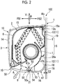
Fig. 2 is a side sectional view of the indoor unit of the air conditioner according to the embodiment of the present invention. -
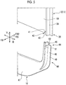
Fig. 3 is a perspective view of a base unit and a bottom panel according to the embodiment of the present invention. -
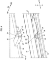
Fig. 4 is a perspective view of a first engagement portion of a base and a second engagement portion of the bottom panel according to the embodiment of the present invention. -
Fig. 5 is a perspective view of a third engagement portion of the base and a fourth engagement portion of the bottom panel according to the embodiment of the present invention. -
Fig. 6 is a perspective view of a support structure of a flap according to the embodiment of the present invention. -
Fig. 7 is a perspective view of a bottom panel fastening structure according to the embodiment of the present invention. -
Fig. 8 is a view when the bottom panel fastening structure according to the embodiment of the present invention is viewed from below. -
Fig. 9 is a perspective view of a cap portion according to the embodiment of the present invention. Description of Embodiments - An
air conditioner 100 includes an indoor unit 1 disposed indoor and an outdoor unit (not illustrated) disposed outdoor. The indoor unit 1 and the outdoor unit are connected to each other by using a pipe. - The indoor unit 1 performs indoor air-conditioning by suctioning air, adjusting temperature and humidity of the air, and then discharging the air.
- Hereinafter, the indoor unit 1 according to an embodiment of the present invention will be described in detail with reference to the drawings.
- In the following description, a front surface, an upper surface, a bottom surface, a back surface, and side surfaces are surfaces expressed based on a state where the indoor unit 1 is attached to a wall surface Wa. The front surface means a front side surface, the upper surface means an indoor ceiling side surface, the bottom surface means an indoor floor side surface, the back surface means a surface on the indoor wall surface Wa side, and the side surfaces mean right and left surfaces facing the indoor wall surface Wa side in a width direction W.
- As illustrated in
Figs. 1 and2 , the indoor unit 1 includes amain body unit 2 having an air-conditioning device 5, and acover portion 3 covering themain body unit 2. - The
main body unit 2 has abase unit 11 fixed to the wall surface Wa and extending in the width direction W along the wall surface Wa, and the air-conditioning device 5 attached to a front FB1 of thebase unit 11. Anair intake port 8 is disposed in an upper portion of a front surface of themain body unit 2. A discharge outlet 9 is disposed in a lower portion of themain body unit 2. - The
cover portion 3 has afront panel 14 covering the front surface of themain body unit 2, atop panel 15 covering an upper surface of themain body unit 2, abottom panel 16 covering a bottom surface of themain body unit 2, and a pair ofside panels 17 respectively covering right and left side portions of themain body unit 2. - A back surface of the
base unit 11 is in surface contact with the wall surface Wa. Thebase unit 11 has aninstallation plate 12 formed of metal, and a base 13 to be fixed to theinstallation plate 12 by using a fastening member such as a bolt, for example. - The
installation plate 12 has a rectangular plate shape, and has a plurality of attachment holes (not illustrated) or ahook 12a (refer toFig. 2 ) for hanging thebase unit 11. Theinstallation plate 12 is fixed to the wall surface Wa by using a wood screw, for example. - The
base 13 supports the air-conditioning device 5, and is a member to which thecover portion 3 is attached. Thebase 13 is formed of a resin. - As illustrated in
Figs. 2 and3 , thebase 13 has arectangular support portion 19 extending in the width direction W, an air-conditioning device holder 20 (base unit main body) disposed on the front FB1 of thesupport portion 19, first engagement portions 23 (refer toFig. 4 ) disposed in a lower portion of the air-conditioning device holder 20 at intervals in the width direction W, a pair ofthird engagement portions 38 disposed in both ends of thesupport portion 19 in the width direction W, and a plurality of screw holes 22 for attaching thebottom panel 16. - The
support portion 19 is a member forming a back surface of themain body unit 2 together with theinstallation plate 12, and has ahook 19a hooked on the hook of theinstallation plate 12. The air-conditioning device holder 20 has a cylindrical innerperipheral surface 20a. The air-conditioning device 5 is held by the air-conditioning device holder 20. - As illustrated in
Fig. 4 , a lower portion of the air-conditioning device holder 20 of thebase 13 is provided with thefirst engagement portion 23 that supports thebottom panel 16 in cooperation with thesecond engagement portion 32 disposed in thebottom panel 16, and a pair of movement regulators 27. - The
first engagement portion 23 has afirst plate portion 24 protruding to the back FB2 from the air-conditioning device holder 20, afirst base portion 25 protruding downwards from a back end of thefirst plate portion 24, and a first protrudingportion 26 protruding to the front FB1 from a lower end of thefirst base portion 25. - The
first plate portion 24 is a plate-shaped member formed such that a main surface of thefirst plate portion 24 is orthogonal to a vertical direction V. - The
first base portion 25 is a plate-shaped member formed such that a main surface of thefirst base portion 25 is orthogonal to a front-back direction FB. - The first protruding
portion 26 has a triangular shape when viewed in the width direction W. The first protrudingportion 26 has afirst engagement surface 28 extending along the width direction W and facing upwards, and afirst introduction surface 29 connecting the front end of thefirst engagement surface 28 and a tip of thefirst base portion 25 to each other. Thefirst introduction surface 29 is tilted to the front FB1 as thefirst introduction surface 29 faces upwards. - The pair of
movement regulators 27 is a portion regulating the movement of thesecond engagement portion 32, which engages with thefirst engagement portion 23, in the width direction W. Themovement regulator 27 is a plate-shaped member formed such that a main surface of themovement regulator 27 is orthogonal to the width direction W. Themovement regulator 27 is provided in the front and back of the first protrudingportion 26 with a predetermined interval. - Three
first engagement portions 23 are formed at intervals in the width direction W. - As illustrated in
Fig. 5 , each of both ends of the base 13 in the width direction W is provided with athird engagement portions 38 supporting thebottom panel 16 in cooperation with afourth engagement portion 44 of the bottom panel 16 (only one of thethird engagement portions 38 is illustrated inFig. 5 ). - The
third engagement portion 38 has a wall-shapedthird base portion 39 disposed in an edge of each of both ends of thesupport portion 19 in the width direction W, and a third protrudingportion 40 disposed in a lower end of thethird base portion 39. Thethird base portion 39 is a plate shape portion protruding to the front FB1 from an end portion of thesupport portion 19 in the width direction W. - The third protruding
portion 40 is a member that is disposed in the lower end of thethird base portion 39 and protrudes inward in the width direction W. The third protrudingportion 40 has athird engagement surface 41 facing upwards, and a thirdintroduction tilting surface 42 that connects a tip of thethird engagement surface 41 and the lower end of thethird base portion 39 to each other and is gradually increased inward in the width direction W. - As illustrated in
Fig. 3 , a lower portion of the air-conditioning device holder 20 of thebase 13 is provided with the plurality of screw holes 22 for attaching thebottom panel 16. The screw holes 22 are configuration elements of a bottompanel fastening structure 64 which will be described later. - The
screw hole 22 is formed in a screwhole plate portion 30 protruding to the front FB1 from the air-conditioning device holder 20. - The air-
conditioning device 5 has aheat exchanger 6, a blower fan 7, and aflap 10. - The blower fan 7 is a cross flow fan extending in the width direction W.
- The
heat exchanger 6 is disposed to surround the blower fan 7 from an outer periphery. - In the lower portion of the air-
conditioning device 5, the discharge outlet 9 for blowing the air from the blower fan 7 into a room is disposed facing downwards, facing obliquely downwards, or facing forwards. - The
flap 10 that covers the discharge outlet 9 from the outer side such that the discharge outlet 9 can be opened and closed is disposed on the downstream side of the discharge outlet 9. When theair conditioner 100 is operated, theflap 10 is in an open state and can adjust the tilting angle thereof in order to adjust the direction of the air from the discharge outlet 9 in the vertical direction V. When theair conditioner 100 is stopped, theflap 10 is in a closed state and can cover the discharge outlet 9 together with the surface of thecover portion 3 that is around theflap 10. - As shown in
Figs. 2 and6 , theflap 10 has a flapmain body 50 having a plate shape and asupport structure 51 supporting the flapmain body 50. The flapmain body 50 is formed of a molded body formed in a substantially plate shape. The length of the flapmain body 50 in the width direction W corresponds to the discharge outlet 9. Aback edge 50a of the flapmain body 50 extends in the width direction W. Theflap 10 can adjust the size of the opening portion of the discharge outlet 9 by a rotation mechanism (not illustrated). - The
support structure 51 is disposed on a back end side of the flapmain body 50. - The
support structure 51 includes anarm 52 supporting theflap 10 such that theflap 10 is rotatable around thebase 13. Thearm 52 has an armmain body 53, arotation connector 54 that is disposed in one end of the armmain body 53 and is connected to the base 13 so as to be rotatable, and a fixingportion 55 that is disposed in the other end of the armmain body 53 and is fixed to the back end of the flapmain body 50. - The arm
main body 53 is formed to be greatly curved in a semicircular shape when viewed in the width direction W. The armmain body 53 is convex upwards when theair conditioner 100 is in an operation state (theflap 10 is in an open state). - The
rotation connector 54 has acutout portion 54a. Thecutout portion 54a of therotation connector 54 is disposed in the lower portion of thebase 13, and can be fitted to a rotation shaft (not illustrated) rotated around an axis extending in the width direction W. Thecutout portion 54a of therotation connector 54 is formed in a substantially C-shape. An opening of thecutout portion 54a of therotation connector 54 faces downwards when theair conditioner 100 is in the operation state (theflap 10 is in the open state). - Next, the
cover portion 3 covering themain body unit 2 will be described. - As illustrated in
Fig. 1 , thefront panel 14 is detachably disposed on the front surface of themain body unit 2. Thefront panel 14 covers the front surface of themain body unit 2, and the air is suctioned into themain body unit 2 from a space between thefront panel 14 and themain body unit 2. - The
top panel 15 is detachably disposed on the upper surface of themain body unit 2. Thetop panel 15 covers the upper surface of themain body unit 2. - The pair of
side panels 17 is detachably disposed in the respective right and left side portions of themain body unit 2. The pair ofside panels 17 covers the side surfaces of themain body unit 2. - The
bottom panel 16 is detachably disposed on the bottom surface of themain body unit 2. Thebottom panel 16 covers the bottom surface of themain body unit 2. - As illustrated in
Figs. 2 and3 , thebottom panel 16 has a bottom panelmain body 47, a pair ofstay portions 48 extending upwards from both ends of the bottom panelmain body 47 in the width direction W, threesecond engagement portions 32 disposed on the upper surface of the bottom panelmain body 47, a plurality ofcross ribs 57 disposed on the upper surface of the bottom panelmain body 47, afirst rib 18 protruding to the back FB2 from a back end of the bottom panelmain body 47, and asecond rib 21 protruding upwards from a front end of the bottom panelmain body 47. Afront end 47a of the bottom panelmain body 47 extends along theback edge 50a of the flapmain body 50. A gap is formed in the width direction W between thefront end 47a of the bottom panelmain body 47 and theback edge 50a of the flapmain body 50. - The
second rib 21 is formed such that wind generated by the blower fan 7 collides with thesecond rib 21. - As illustrated in
Fig. 4 , thesecond engagement portion 32 that supports thebottom panel 16 in cooperation with thefirst engagement portion 23 disposed in thebase 13 is disposed on the upper surface of the bottom panelmain body 47. Thesecond engagement portion 32 has asecond base portion 33, and a second protrudingportion 34 protruding to the back FB2 from an upper end of thesecond base portion 33. - The
second base portion 33 is a member protruding upwards and extending in the width direction W. - The second protruding
portion 34 has a triangular shape when viewed in the width direction W. The second protrudingportion 34 has asecond engagement surface 35 extending along the width direction W and facing downwards, and asecond introduction surface 36 connecting the back end of thesecond engagement surface 35 and a tip of thesecond base portion 33 to each other. Thesecond introduction surface 36 is tilted to the front FB1 as thesecond introduction surface 36 faces upwards. - Three
second engagement portions 32 are formed at intervals in the width direction W. Thesecond engagement portion 32 is formed at a position corresponding to thefirst engagement portion 23. - As illustrated in
Fig. 5 , each of thestay portions 48 has a stay portionmain body 49, and afourth engagement portion 44 disposed in an upper end of the stay portionmain body 49. Thefourth engagement portion 44 is a member supporting both ends of thebottom panel 16 in the width direction W in cooperation with thethird engagement portion 38 of thebase 13. - The stay portion
main body 49 is a plate-shaped member extending in the vertical direction V. The main surface of the stay portionmain body 49 is oriented in the front-back direction FB. - The
fourth engagement portion 44 has afourth base portion 45 protruding upwards together with the stay portionmain body 49, and a fourth protrudingportion 46 protruding outward in the width direction W from an upper end of thefourth base portion 45. - The
fourth base portion 45 has a plate shape, and is formed to protrude to the front FB1 from the front surface of the stay portionmain body 49. The main surface of thefourth base portion 45 is oriented in the width direction W. - The fourth protruding
portion 46 has afourth engagement surface 61 facing downwards, and a fourthintroduction tilting surface 62 that connects a tip of thefourth engagement surface 61 and the upper end of thefourth base portion 45 to each other and is gradually lowered outward in the width direction W. - As illustrated in
Figs. 7 ,8 , and9 , the bottom panelmain body 47 of thebottom panel 16 is attached to thebase 13 by using the bottompanel fastening structure 64. - The bottom
panel fastening structure 64 has the plurality of screw holes 22 (refer toFig. 3 ) disposed in thebase 13, an opening portion 65 (refer toFig. 8 ) formed in thebottom panel 16, a fastening target plate portion 66 (refer toFig. 7 ), a baffle member 67, and acap portion 68 covering the openingportion 65. - The opening
portion 65 is disposed at a position corresponding to thescrew hole 22. The openingportion 65 has a rectangular shape. The openingportion 65 has a linearfirst edge 65a and a linearsecond edge 65b disposed on a side opposite to thefirst edge 65a. - The
cap portion 68 is a component for concealing a screw used in the bottompanel fastening structure 64. Thecap portion 68 can be attached to the openingportion 65. Thecap portion 68 can be rotated around arotation shaft portion 73 attached to thefirst edge 65a of the openingportion 65. - The fastening
target plate portion 66 has a plate shape formed to be tilted with respect to the main surface of the bottom panelmain body 47. The fasteningtarget plate portion 66 is connected to thefirst edge 65a of the openingportion 65, and is tilted upwards as the fasteningtarget plate portion 66 is separated from thefirst edge 65a. - A through-hole 72 into which a shaft portion of the screw, which fastens the
bottom panel 16, is inserted is formed in a central portion of the fasteningtarget plate portion 66. - The fastening
target plate portion 66 is connected to the bottom panelmain body 47 by using afirst connection plate 69 and a pair ofsecond connection plates 70. Thefirst connection plate 69 connects anupper end 66a of the fasteningtarget plate portion 66 and thesecond edge 65b to each other, thesecond edge 65b being disposed on the opposite side of the openingportion 65 from thefirst edge 65a. The pair ofsecond connection plates 70 connects alateral side 66c of the fasteningtarget plate portion 66 and aside edge 65c of the openingportion 65 to each other. - A gap G1 is formed between a
lower edge 66b which is disposed on the opposite side of the fasteningtarget plate portion 66 from a portion connected to thefirst connection plate 69, and thefirst edge 65a of the openingportion 65. Thesecond connection plate 70 has anengagement hole 71 with which a cap projection 74 (to be described later) engages. - As illustrated in
Fig. 9 , thecap portion 68 is a rectangular plate-shaped member corresponding to the openingportion 65. Therotation shaft portion 73 is formed on afirst side 68a of thecap portion 68. Therotation shaft portion 73 protrudes in a direction extending along thefirst side 68a of thecap portion 68. Therotation shaft portion 73 is rotatably supported by bearing portions (not illustrated) formed on the pair ofsecond connection plates 70. - A pair of
cap projections 74 protruding in a direction extending along thesecond side 68b is formed on asecond side 68b that is disposed on the opposite side of thecap portion 68 from thefirst side 68a. Thecap projection 74 is a hemispherical projection engaging with theengagement hole 71 of thesecond connection plate 70. - The bottom
panel fastening structure 64 according to the present embodiment has the baffle member 67 connecting thefirst edge 65a of the openingportion 65 and thelower edge 66b of the fasteningtarget plate portion 66 to each other. The baffle member 67 is formed to close a part of the gap G1 between thelower edge 66b of the fasteningtarget plate portion 66 and thefirst edge 65a of the openingportion 65. - As illustrated in
Figs. 3 and7 , the upper surface of the bottom panelmain body 47 has afifth rib 76 extending in the width direction W, and a plurality ofsixth ribs 77 orthogonal to thefifth rib 76 and extending in the front-back direction FB. - The
fifth rib 76 is a plate-shaped member protruding upwards from the upper surface of the bottom panelmain body 47. The main surface of thefifth rib 76 is orthogonal to the upper surface of the bottom panelmain body 47. Thefifth rib 76 is formed on the front side of the bottom panelmain body 47. - The plurality of
sixth ribs 77 is formed on the back FB2 of thefifth rib 76. The plurality ofsixth ribs 77 is formed at an interval in the width direction W. - The
cross rib 57 has athird rib 58 and afourth rib 59 which are formed to cross each other. - The
third rib 58 is a plate-shaped member protruding upwards from the upper surface of the bottom panelmain body 47. Thethird rib 58 extends along the upper surface of the bottom panelmain body 47 and in a direction tilted to the width direction W. The main surface of thethird rib 58 is orthogonal to the upper surface of the bottom panelmain body 47. - Similar to the
third rib 58, thefourth rib 59 is a plate-shaped member protruding upwards from the upper surface of the bottom panelmain body 47. Thefourth rib 59 extends along the upper surface of the bottom panelmain body 47 and in the direction tilted to the width direction W. The main surface of thefourth rib 59 is orthogonal to the upper surface of the bottom panelmain body 47. - The
cross rib 57 is formed in a rectangular region formed by the two adjacentsixth ribs 77 and thefifth rib 76. Thethird rib 58 and thefourth rib 59 which configure thecross rib 57 are formed so as to form diagonal lines of the above-described rectangular region. - The height of the
cross rib 57 from the upper surface of the bottom panelmain body 47 can be set to 3 mm, for example. The height of thecross rib 57 from the upper surface of the bottom panelmain body 47 can be appropriately changed in accordance with the thickness of the bottom panelmain body 47. In order to facilitate molding of thebottom panel 16, a circular rib may be disposed in a cross point of thecross rib 57. - The number of the
cross ribs 57 can be appropriately changed. However, in order to improve strength, it is preferable that thecross ribs 57 are disposed as many as possible. - As illustrated in
Figs. 2 and3 , the bottom panelmain body 47 of thebottom panel 16 has afront end 47a extending along theback edge 50a of the flapmain body 50, and acurved part 79 which curves upwards from thefront end 47a towards the back FB2. Thecurved part 79 is formed such that a gap G2 between aback end 47b of thecurved part 79 and the wall surface Wa is evenly disposed in the width direction W. In other words, theback end 47b of thecurved part 79 is located on the front side of the back surface of thebase unit 11. - The
bottom panel 16 has thefirst rib 18 protruding to the back FB2 from theback end 47b of thecurved part 79. Thefirst rib 18 is a plate-shaped member extending in the width direction W. The main surface of thefirst rib 18 is substantially horizontal. Thefirst rib 18 is formed such that an angle formed between the front end of thefirst rib 18 and the back end of thecurved part 79 of the bottom panelmain body 47 is from 90° to 150°. Thefirst rib 18 is formed to cover the gap G2 between thecurved part 79 and the wall surface Wa. - The bottom panel
main body 47 of thebottom panel 16 has thesecond rib 21 protruding upwards from thefront end 47a of the bottom panelmain body 47. - The
second rib 21 is a plate-shaped member extending in the width direction W. The main surface of thesecond rib 21 is oriented to the front FB1. Thesecond rib 21 is formed such that an angle formed between the lower end of thesecond rib 21 and the back end of thefront end 47a of the bottom panelmain body 47 is from 90° to 120°. As illustrated inFig. 4 , thesecond rib 21 is formed to have anescape portion 80 in order to avoid interference with thearm 52 of theflap 10. - Next, a method of attaching the
bottom panel 16 of the indoor unit 1 of theair conditioner 100 according to the present embodiment will be described. - The
bottom panel 16 is attached by causing thefirst engagement portion 23 disposed in the lower portion of thebase 13 and thesecond engagement portion 32 disposed on the upper surface of the bottom panelmain body 47 to engage with each other, causing thethird engagement portion 38 disposed in both ends of the base 13 in the width direction W and thefourth engagement portion 44 disposed in thestay portion 48 of thebottom panel 16 to engage with each other, and fastening the bottom panelmain body 47 to thebase 13 by using the bottompanel fastening structure 64. - The bottom panel
main body 47 is supported by engagement between the first protrudingportion 26 of thefirst engagement portion 23 and the second protrudingportion 34 of thesecond engagement portion 32. - Both ends of the bottom panel
main body 47 in the width direction W are supported by engagement between the third protrudingportion 40 of thethird engagement portion 38 and the fourth protrudingportion 46 of thefourth engagement portion 44. Thefourth engagement portion 44 is inserted from below thethird engagement portion 38, thereby enabling thethird engagement portion 38 and thefourth engagement portion 44 to engage with each other. - In this case, the fourth
introduction tilting surface 62 of thefourth engagement portion 44 slides on the thirdintroduction tilting surface 42 of thethird engagement portion 38, and thefourth base portion 45 of thefourth engagement portion 44 is elastically deformed. Thefourth base portion 45 has a plate shape, and the main surface of thefourth base portion 45 is oriented in the width direction W. Accordingly, thefourth base portion 45 is easily deformed inward in the width direction W. - The bottom panel
main body 47 can be fastened to thebase unit 11 by using the bottompanel fastening structure 64. Specifically, the fasteningtarget plate portion 66 of the bottom panelmain body 47 is fastened to the screwhole plate portion 30 of the base 13 by using a screw. In this manner, the bottom panelmain body 47 can be fixed to thebase 13. - After the bottom panel
main body 47 is fixed, the openingportion 65 of the bottom panelmain body 47 can be closed by using thecap portion 68. - Next, an operation of the
first rib 18 will be described. - The
curved part 79 is disposed in the bottom panelmain body 47 according to the present embodiment. Accordingly, the indoor unit 1 can be designed so as not to give a user a feeling of pressure. Thefirst rib 18 is formed in thecurved part 79. Accordingly, the strength of thecurved part 79 can be improved. In addition, when the indoor unit 1 is tilted to the front FB1 due to the self-weight, thefirst rib 18 is pushed against the wall surface Wa. - Next, an operation of the
second rib 21 will be described. - When cooling is performed, cold air is discharged from the discharge outlet 9. In this case, when the
second rib 21 is not provided, the cold air is blown out from a gap between theflap 10 and thebottom panel 16. Accordingly, dew condensation may occur. Since thesecond rib 21 is disposed in thebottom panel 16 according to the present embodiment, the cold air blown from the gap between theflap 10 and thebottom panel 16 is blocked. - According to the embodiment, the
curved part 79 is disposed in the bottom panelmain body 47. Accordingly, the indoor unit 1 can be designed so as not to give a user a feeling of pressure. In addition, thefirst rib 18 is disposed in thebottom panel 16. Accordingly, when the indoor unit 1 is tilted to the front FB1 due to the self-weight, thefirst rib 18 is pushed against the wall surface Wa, and thereby it is possible to prevent the indoor unit 1 from being tilted to the front FB1. - In addition, the baffle member 67 is disposed in the
bottom panel 16. Accordingly, when the openingportion 65 is covered using thecap portion 68 after thebottom panel 16 is fastened to thebase unit 11, it is possible to prevent thecap portion 68 from entering the inside of thebottom panel 16. - In addition, the
second rib 21 blocks cold air when cooling is performed. In this manner, dew condensation can be prevented. That is, it is possible to prevent thebottom panel 16 and theflap 10 from being cooled due to the cold air blowing out from between thebottom panel 16 and theflap 10 when the cooling is performed. - In addition, the
bottom panel 16 extends in the width direction W. Accordingly, thebottom panel 16 thermally expands so as to increase the width in the width direction W. In a case where thefirst engagement portion 23 and thesecond engagement portion 32 are formed such that the first protrudingportion 26 of thefirst engagement portion 23 and the second protrudingportion 34 of thesecond engagement portion 32 protrude in the width direction W, thebottom panel 16 thermally expands in the width direction W. In this manner, an engagement margin decreases, and both the engagement portions are likely to disengage from each other. - On the other hand, according to the configuration of the present invention, the first protruding
portion 26 of thefirst engagement portion 23 and the second protrudingportion 34 of thesecond engagement portion 32 protrude in the front-back direction FB. In this manner, it is possible to prevent thefirst engagement portion 23 and thesecond engagement portion 32 from insufficiently engaging with each other by thebottom panel 16 thermally expanding in the width direction W. That is, even in a case where thebottom panel 16 thermally expands in the width direction W, there is no influence on the engagement margin in the front-back direction FB. Therefore, it is possible to prevent the disengagement. - In addition, the
cross rib 57 is disposed on the upper surface of the bottom panelmain body 47. Accordingly, thebottom panel 16 can have a strong structure. That is, even in a case where thebottom panel 16 has a long shape in the width direction W, the strength can be improved without increasing the plate thickness of thebottom panel 16. - In addition, the
third engagement portion 38 disposed in both ends of the base 13 in the width direction W and thefourth engagement portion 44 disposed in both ends of thebottom panel 16 are caused to engage with each other. In this manner, it is possible to prevent both end portions of thebottom panel 16 from being lowered downwards. - Hitherto, the embodiment according to the present invention has been described in detail with reference to the drawings. However, the specific configurations are not limited to this embodiment. The present invention also includes any design change within the scope not departing from the gist of the present invention.
- The above-described embodiment adopts a configuration in which the first protruding
portion 26 of thefirst engagement portion 23 disposed in the base 13 protrudes to the front FB1 in the front-back direction FB and the second protrudingportion 34 of thesecond engagement portion 32 disposed in thebottom panel 16 protrudes to the back FB2 in the front-back direction FB. However, the present invention is not limited thereto. That is, a configuration in which the first protrudingportion 26 of thefirst engagement portion 23 protrudes to the back FB2 in the front-back direction FB, and the second protrudingportion 34 of thesecond engagement portion 32 protrudes to the front FB1 in the front-back direction FB may be adopted. - According to the present invention, it is possible to adopt a design for not giving a user a feeling of pressure by disposing the curved part in the bottom panel. In addition, the first rib is disposed in the bottom panel. Accordingly, when the indoor unit is tilted to the front due to the self-weight, the first rib is pushed against the wall surface. In this manner, it is possible to prevent the indoor unit from being tilted to the front.
-
- 1 indoor unit
- 2 main body
- 3 cover portion
- 5 air-conditioning device
- 6 heat exchanger
- 7 blower fan
- 8 intake port
- 9 discharge outlet
- 10 flap
- 11 base unit
- 12 installation plate
- 13 base
- 14 front panel
- 15 top panel
- 16 bottom panel
- 17 side panel
- 18 first rib
- 19 support portion
- 20 air-conditioning device holder (base unit main body)
- 21 second rib
- 22 screw hole
- 23 first engagement portion
- 24 first plate portion
- 25 first base portion
- 26 first protruding portion
- 27 movement regulator
- 28 first engagement surface
- 29 first introduction surface
- 30 screw hole plate portion
- 32 second engagement portion
- 33 second base portion
- 34 second protruding portion
- 35 second engagement surface
- 36 second introduction surface
- 38 third engagement portion
- 39 third base portion
- 40 third protruding portion
- 41 third engagement surface
- 42 third introduction tilting surface
- 44 fourth engagement portion
- 45 fourth base portion
- 46 fourth protruding portion
- 47 bottom panel main body
- 48 stay portion
- 49 stay portion main body
- 50 flap main body
- 50a back edge
- 51 support structure
- 52 arm
- 53 arm main body
- 54 rotation connector
- 55 fixing portion
- 57 cross rib
- 58 third rib
- 59 fourth rib
- 61 fourth engagement surface
- 62 fourth introduction tilting surface
- 64 bottom panel fastening structure
- 65 opening portion
- 66 fastening target plate portion
- 67 baffle member
- 68 cap portion
- 69 first connection plate
- 70 second connection plate
- 71 engagement hole
- 72 through-hole
- 73 rotation shaft portion
- 74 cap projection
- 76 fifth rib
- 77 sixth rib
- 79 curved part
- 80 escape portion
- 100 air conditioner
- FB front-back direction
- FB1 front
- FB2 back
- V vertical direction
- W width direction
- Wa wall surface
Claims (10)
- An indoor unit of an air conditioner, comprising:a main body unit havinga base unit fixed to a wall surface and extending in a width direction along the wall surface, andan air-conditioning device which is attached to a front of the base unit, and has a heat exchanger, a blower fan, and a flap that has a plate shape and has a back edge extending in the width direction; anda bottom panel covering a bottom surface of the main body unit, and havinga front end extending along a back edge of the flap disposed in a lower portion of the main body unit,a curved part which curves upwards from the front end towards a back and which is positioned with a back end forwards of a back surface of the base unit, anda first rib protruding to the back from the back end of the curved part.
- The indoor unit of an air conditioner according to Claim 1, further comprising:a bottom panel fastening structure that fastens the bottom panel to the base unit,wherein the bottom panel fastening structure hasa screw hole disposed in the base unit,an opening portion disposed on a main surface of the bottom panel, and having a linear first edge and a linear second edge disposed on a side opposite to the first edge,a cap portion covering the opening portion,a fastening target plate portion connected to the first edge, tilted upwards as the fastening target plate portion is separated from the first edge, and having a through-hole corresponding to the screw hole, anda baffle member connecting an upper side end portion of the fastening target plate portion and the second edge of the opening portion to each other.
- The indoor unit of an air conditioner according to Claim 1 or 2,
wherein the bottom panel has a second rib protruding upwards from the front end of the bottom panel such that wind generated by the blower fan collides with the second rib. - The indoor unit of an air conditioner according to any one of Claims 1 to 3, further comprising:a first engagement portion disposed in the base unit and havinga first base portion protruding downwards and extending in the width direction, anda first protruding portion protruding to one side in a front-back direction from a lower end of the first base portion; anda second engagement portion disposed on an upper surface of the bottom panel, engaging with the first engagement portion, and havinga second base portion protruding upwards and extending in the width direction, anda second protruding portion protruding to the other side in the front-back direction from an upper end of the second base portion.
- The indoor unit of an air conditioner according to any one of Claims 1 to 4,
wherein the bottom panel has a cross rib havinga third rib disposed on an upper surface of the bottom panel, extending along the upper surface and in a direction tilted to the width direction, and protruding upwards, anda fourth rib crossing the third rib, extending along the upper surface and in the direction tilted to the width direction, and protruding upwards. - The indoor unit of an air conditioner according to any one of Claims 1 to 5, further comprising:a pair of third engagement portions havingthird base portions respectively disposed in both ends of the base unit in the width direction, andthird protruding portions each protruding inward in the width direction from each of the third base portions; anda pair of fourth engagement portions that is disposed in both ends of the bottom panel in the width direction, that engages with the third engagement portions, and that hasfourth base portions extending upwards, andfourth protruding portions each protruding outward in the width direction from an upper portion of each of the fourth base portions.
- An indoor unit of an air conditioner, comprising:a main body unit havinga base unit fixed to a wall surface and extending in a width direction along the wall surface, andan air-conditioning device which is attached to a front of the base unit, and has a heat exchanger, a blower fan, and a flap that has a plate shape;a bottom panel covering a bottom surface of the main body unit; anda bottom panel fastening structure that fastens the bottom panel to the base unit,wherein the bottom panel fastening structure hasa screw hole disposed in the base unit,an opening portion disposed on a main surface of the bottom panel, and having a linear first edge and a linear second edge disposed on a side opposite to the first edge,a cap portion covering the opening portion,a fastening target plate portion connected to the first edge, tilted upwards as the fastening target plate portion is separated from the first edge, and having a through-hole corresponding to the screw hole, anda baffle member connecting an upper side end portion of the fastening target plate portion and the second edge of the opening portion to each other.
- An indoor unit of an air conditioner, comprising:a main body unit havinga base unit fixed to a wall surface and extending in a width direction along the wall surface, anda heat exchanger and a blower fan which are attached to a front of the base unit; anda bottom panel covering a bottom surface of the main body unit,wherein the base unit hasa base unit main body, anda first engagement portion having a first base portion protruding downwards from the base unit main body and extending in a width direction, and a first protruding portion protruding to one side in a front-back direction from a lower end of the first base portion, andwherein the bottom panel hasa bottom panel main body having a plate shape,a second engagement portion that is disposed on an upper surface of the bottom panel main body, engages with the first engagement portion, and has a second base portion protruding upwards and extending in the width direction, and a second protruding portion protruding to the other side in the front-back direction from an upper end of the second base portion.
- An indoor unit of an air conditioner, comprising:a main body unit that extends in a width direction and has an air-conditioning device having a heat exchanger and a blower fan; anda bottom panel covering a bottom surface of the main body unit, and havinga bottom panel main body extending in the width direction and having a plate shape, anda cross rib having a third rib that is disposed on an upper surface of the bottom panel main body, extends along the upper surface and in a direction tilted to the width direction, and protrudes upwards, and a fourth rib that crosses the third rib, extends along the upper surface and in the direction tilted to the width direction, and protrudes upwards.
- An indoor unit of an air conditioner, comprising:a main body unit havinga base unit fixed to a wall surface and extending in a width direction along the wall surface, andan air-conditioning device which is attached to a front of the base unit, and has a heat exchanger and a blower fan; anda bottom panel covering a bottom surface of the main body unit,wherein the base unit hasa base unit main body, anda pair of third engagement portions having third base portions respectively disposed in both ends of the base unit main body in the width direction, and third protruding portions each protruding inward in the width direction from each of the third base portions, andwherein the bottom panel hasa bottom panel main body extending in the width direction and having a plate shape,a pair of fourth engagement portions that is disposed in both ends of the bottom panel main body in the width direction, that engages with the third engagement portions, and that hasfourth base portions extending upwards, andfourth protruding portions each protruding outward in the width direction from an upper portion of each of the fourth base portions.
Applications Claiming Priority (2)
| Application Number | Priority Date | Filing Date | Title |
|---|---|---|---|
| JP2016235972A JP2018091563A (en) | 2016-12-05 | 2016-12-05 | Air conditioner indoor unit |
| PCT/JP2017/043474 WO2018105555A1 (en) | 2016-12-05 | 2017-12-04 | Indoor unit of air-conditioner |
Publications (1)
| Publication Number | Publication Date |
|---|---|
| EP3534085A1 true EP3534085A1 (en) | 2019-09-04 |
Family
ID=62491511
Family Applications (1)
| Application Number | Title | Priority Date | Filing Date |
|---|---|---|---|
| EP17877627.4A Withdrawn EP3534085A1 (en) | 2016-12-05 | 2017-12-04 | Indoor unit of air-conditioner |
Country Status (3)
| Country | Link |
|---|---|
| EP (1) | EP3534085A1 (en) |
| JP (1) | JP2018091563A (en) |
| WO (1) | WO2018105555A1 (en) |
Families Citing this family (2)
| Publication number | Priority date | Publication date | Assignee | Title |
|---|---|---|---|---|
| KR101185583B1 (en) * | 2011-12-27 | 2012-09-24 | 김영재 | A suture which need not be knotted and a kit comprising the suture |
| CN113899067A (en) * | 2020-06-22 | 2022-01-07 | 广东美的制冷设备有限公司 | End cover assembly, face frame assembly and air conditioner indoor unit |
Family Cites Families (5)
| Publication number | Priority date | Publication date | Assignee | Title |
|---|---|---|---|---|
| JPS5819054Y2 (en) * | 1979-12-29 | 1983-04-19 | 河西工業株式会社 | Housing structure of automotive air conditioning equipment |
| JPS59134439A (en) * | 1983-01-19 | 1984-08-02 | Sanyo Electric Co Ltd | Wall hanging type air conditioner unit |
| JP3277099B2 (en) | 1995-08-22 | 2002-04-22 | 東芝キヤリア株式会社 | Indoor unit of air conditioner |
| JP2001193958A (en) * | 2000-12-12 | 2001-07-17 | Sharp Corp | Air conditioner indoor unit |
| JP3882790B2 (en) * | 2003-06-23 | 2007-02-21 | ダイキン工業株式会社 | Air conditioner indoor unit |
-
2016
- 2016-12-05 JP JP2016235972A patent/JP2018091563A/en active Pending
-
2017
- 2017-12-04 WO PCT/JP2017/043474 patent/WO2018105555A1/en not_active Ceased
- 2017-12-04 EP EP17877627.4A patent/EP3534085A1/en not_active Withdrawn
Also Published As
| Publication number | Publication date |
|---|---|
| JP2018091563A (en) | 2018-06-14 |
| WO2018105555A1 (en) | 2018-06-14 |
Similar Documents
| Publication | Publication Date | Title |
|---|---|---|
| EP2899472B1 (en) | Indoor unit for air conditioner having wind visors | |
| US9982908B2 (en) | Air conditioner | |
| KR100957122B1 (en) | Ventilation duct diffuser | |
| US9903600B2 (en) | Wind direction adjusting device of air-conditioning apparatus and air-conditioning apparatus | |
| EP3460350A1 (en) | Indoor unit of air-conditioner | |
| AU2019242466B2 (en) | Ceiling-embedded air conditioner | |
| WO2013047240A1 (en) | Ceiling-embedded air-conditioner | |
| EP3441693B1 (en) | Air conditioner | |
| JP5660060B2 (en) | Indoor unit | |
| US20250271171A1 (en) | Grille attachment system for a ventilation system | |
| CN112601915B (en) | Air conditioner | |
| JP2018091563A (en) | Air conditioner indoor unit | |
| KR200477238Y1 (en) | Air diffuser | |
| JP2013015288A (en) | Air conditioner | |
| JP2006038380A (en) | Blowout grill device, blowout chamber device and built-in type air conditioner using the same | |
| CN111936798B (en) | Ceiling embedded air conditioner | |
| AU2019242467B2 (en) | Ceiling-embedded air conditioner | |
| JP5195706B2 (en) | Fixed claw structure for wall-mounted indoor unit | |
| CA2578329A1 (en) | Air circulation with releasable air grille | |
| WO2018100766A1 (en) | Ventilation system component and ventilator | |
| KR20170019290A (en) | Indoor unit for air conditoiner | |
| KR20180089783A (en) | Air conditioner |
Legal Events
| Date | Code | Title | Description |
|---|---|---|---|
| PUAI | Public reference made under article 153(3) epc to a published international application that has entered the european phase |
Free format text: ORIGINAL CODE: 0009012 |
|
| 17P | Request for examination filed |
Effective date: 20190529 |
|
| AK | Designated contracting states |
Kind code of ref document: A1 Designated state(s): AL AT BE BG CH CY CZ DE DK EE ES FI FR GB GR HR HU IE IS IT LI LT LU LV MC MK MT NL NO PL PT RO RS SE SI SK SM TR |
|
| AX | Request for extension of the european patent |
Extension state: BA ME |
|
| STAA | Information on the status of an ep patent application or granted ep patent |
Free format text: STATUS: THE APPLICATION HAS BEEN WITHDRAWN |
|
| 18W | Application withdrawn |
Effective date: 20190910 |