EP3534083A1 - Air-conditioning indoor unit - Google Patents
Air-conditioning indoor unit Download PDFInfo
- Publication number
- EP3534083A1 EP3534083A1 EP17863931.6A EP17863931A EP3534083A1 EP 3534083 A1 EP3534083 A1 EP 3534083A1 EP 17863931 A EP17863931 A EP 17863931A EP 3534083 A1 EP3534083 A1 EP 3534083A1
- Authority
- EP
- European Patent Office
- Prior art keywords
- air
- blow
- air conditioning
- switching mechanism
- temperature
- Prior art date
- Legal status (The legal status is an assumption and is not a legal conclusion. Google has not performed a legal analysis and makes no representation as to the accuracy of the status listed.)
- Granted
Links
Images



Classifications
-
- F—MECHANICAL ENGINEERING; LIGHTING; HEATING; WEAPONS; BLASTING
- F24—HEATING; RANGES; VENTILATING
- F24F—AIR-CONDITIONING; AIR-HUMIDIFICATION; VENTILATION; USE OF AIR CURRENTS FOR SCREENING
- F24F11/00—Control or safety arrangements
- F24F11/70—Control systems characterised by their outputs; Constructional details thereof
- F24F11/72—Control systems characterised by their outputs; Constructional details thereof for controlling the supply of treated air, e.g. its pressure
- F24F11/74—Control systems characterised by their outputs; Constructional details thereof for controlling the supply of treated air, e.g. its pressure for controlling air flow rate or air velocity
-
- F—MECHANICAL ENGINEERING; LIGHTING; HEATING; WEAPONS; BLASTING
- F24—HEATING; RANGES; VENTILATING
- F24F—AIR-CONDITIONING; AIR-HUMIDIFICATION; VENTILATION; USE OF AIR CURRENTS FOR SCREENING
- F24F11/00—Control or safety arrangements
- F24F11/70—Control systems characterised by their outputs; Constructional details thereof
- F24F11/72—Control systems characterised by their outputs; Constructional details thereof for controlling the supply of treated air, e.g. its pressure
- F24F11/79—Control systems characterised by their outputs; Constructional details thereof for controlling the supply of treated air, e.g. its pressure for controlling the direction of the supplied air
-
- F—MECHANICAL ENGINEERING; LIGHTING; HEATING; WEAPONS; BLASTING
- F24—HEATING; RANGES; VENTILATING
- F24F—AIR-CONDITIONING; AIR-HUMIDIFICATION; VENTILATION; USE OF AIR CURRENTS FOR SCREENING
- F24F2110/00—Control inputs relating to air properties
- F24F2110/10—Temperature
Definitions
- the present invention relates to an air conditioning indoor unit.
- Patent Literature 1 JP 2013-076530 A
- an air conditioning indoor unit configured to send air, from which heat is taken at a heat exchanger, horizontally or substantially horizontally to cool an air conditioning target space. Air blowing out horizontally or substantially horizontally from the air conditioning indoor unit generates a circulating airflow in the air conditioning target space to facilitate uniform conditioning of air in the entire air conditioning target space.
- An object of the present invention is to provide an air conditioning indoor unit configured to facilitate relief of temperature unevenness in an air conditioning target space during cooling operation to achieve the highly comfortable air conditioning target space.
- An air conditioning indoor unit includes a casing, a heat exchanger, a fan, an airflow direction switching mechanism, and a switching mechanism control unit.
- the casing has an intake port and a blow-out port.
- the heat exchanger exchanges heat with air sucked through the intake port to draw the heat from the air.
- the fan sends the air exchanged heat at the heat exchanger out of the blow-out port.
- the airflow direction switching mechanism switches an airflow direction of blow-out air from the blow-out port at least between a first direction and a second direction.
- the first direction is horizontal or substantially horizontal direction.
- the second direction is vertically downward or substantially vertically downward direction.
- the switching mechanism control unit controls operation of the airflow direction switching mechanism so that the blow-out air temporarily blows out in the second direction when temperature unevenness is detected or presumed in the air conditioning target space while the blow-out air is blowing out in the first direction.
- the air conditioning indoor unit blows out air in the second direction (vertically downward or substantially vertically downward) in a case where temperature unevenness is detected or presumed in the air conditioning target space when cooling (including dehumidifying) is performed while blowing out air in the first direction (horizontally or substantially horizontally).
- This configuration achieves supply of conditioned air to an area vertically below the air conditioning indoor unit, where the blow-out air blowing out in the first direction is unlikely to reach, to relieve the temperature unevenness in the air conditioning target space and provide the comfortable air conditioning target space.
- An air conditioning indoor unit is the air conditioning indoor unit according to the first aspect and further includes a temperature unevenness detection sensor detecting the temperature unevenness and a temperature unevenness detector.
- the temperature unevenness detector detects the temperature unevenness in the air conditioning target space in accordance with a result of measurement by the temperature unevenness detection sensor.
- the switching mechanism control unit controls the operation of the airflow direction switching mechanism so that the blow-out air temporarily blows out in the second direction in accordance with a result of detection by the temperature unevenness detector while the blow-out air blowing out in the first direction.
- the air conditioning indoor unit can accurately detect the temperature unevenness in accordance with the result of measurement by the sensor and relieve the temperature unevenness through control on the airflow direction of the blow-out air.
- An air conditioning indoor unit is the air conditioning indoor unit according to the second aspect and is of a wall-mounted type.
- the temperature unevenness detection sensor includes a first temperature sensor.
- the first temperature sensor measures a temperature of a position below the air conditioning indoor unit.
- the air conditioning indoor unit detects the temperature unevenness in accordance with a result of measurement by the first temperature sensor that measures the temperature of the position below the air conditioning indoor unit of the wall-mounted type to facilitate accurate detection of the temperature unevenness without missing out it.
- An air conditioning indoor unit is the air conditioning indoor unit according to the third aspect, and the temperature unevenness detection sensor further includes a second temperature sensor.
- the second temperature sensor measures a temperature of a position, which is distant from a wall on which the air conditioning indoor unit is installed, in the air conditioning target space.
- the temperature unevenness detector detects the temperature unevenness in the air conditioning target space in accordance with a result of comparison between a measurement value of the first temperature sensor and a measurement value of the second temperature sensor.
- the air conditioning indoor unit detects the temperature unevenness in accordance with measurement results of the temperature of the position, which is distant from the wall on which the air conditioning indoor unit is installed, in the air conditioning target space and the temperature of the position below the air conditioning indoor unit, to facilitate accurate detection of the temperature unevenness without missing out it.
- An air conditioning indoor unit is the air conditioning indoor unit according to the third aspect, and the temperature unevenness detector detects the temperature unevenness in the air conditioning target space in accordance with time change of the temperature measured by the first temperature sensor.
- the air conditioning indoor unit detects the temperature unevenness by means of only the first temperature sensor that measures the temperature of the position below the air conditioning indoor unit of the wall-mounted type, in other words, by means of a relatively simple configuration, and relieves the temperature unevenness through control on the airflow direction of the blow-out air.
- An air conditioning indoor unit is the air conditioning indoor unit according to any one of the first to fifth aspects, and further includes a temperature unevenness presumer.
- the temperature unevenness presumer presumes occurrence of the temperature unevenness in the air conditioning target space in a case where a period in which the blow-out air continuously blows out in the first direction exceeds a first period.
- the switching mechanism control unit controls the operation of the airflow direction switching mechanism so that the blow-out air temporarily blows out in the second direction in accordance with a result of presumption by the temperature unevenness presumer while the blow-out air blowing out in the first direction.
- the air conditioning indoor unit appropriately presumes occurrence of the temperature unevenness based on a feature that the temperature unevenness is likely to occur at a position immediately below the air conditioning indoor unit when air blows out in the first direction, to suppress the occurrence of the temperature unevenness as well as to relieve the temperature unevenness.
- the air conditioning indoor unit includes the temperature unevenness detection sensor
- temperature unevenness may occur at a position where the temperature unevenness detection sensor has difficulty in measuring.
- the occurrence of temperature unevenness is presumed when the blow-out air blows out in the first direction continuously for a long period. This configuration can thus relieve the temperature unevenness in the air conditioning target space, even if there is a difficulty for the sensor to detect the temperature unevenness.
- An air conditioning indoor unit is the air conditioning indoor unit according to any one of the first to sixth aspects, and further includes a space temperature sensor, a space humidity sensor, and a control permission unit.
- the space temperature sensor detects a temperature of the air conditioning target space.
- the space humidity sensor detects a humidity of the air conditioning target space.
- the control permission unit permits the switching mechanism control unit to control the operation of the airflow direction switching mechanism.
- the control permission unit permits the switching mechanism control unit to control the operation of the airflow direction switching mechanism so that the blow-out air blows out in the second direction in a case where a condition that the temperature detected by the space temperature sensor is equal to or less than a predetermined temperature and the humidity detected by the space humidity sensor is equal to or less than a predetermined humidity continues for a second period or more.
- the air conditioning indoor unit prioritizes to blow out air in the first direction to facilitate generation of a circulating airflow in the air conditioning target space until the temperature and the humidity of the air conditioning target space satisfy predetermined conditions.
- This configuration can thus further improve in comfort through relief of temperature unevenness after initially securing comfort in the entire air conditioning target space.
- An air conditioning indoor unit is the air conditioning indoor unit according to the seventh aspect, and the control permission unit further permits the switching mechanism control unit to control the operation of the airflow direction switching mechanism so that the blow-out air blows out in the second direction in a case where a continuous operation period after the air conditioning indoor unit starts blowing out the blow-out air in the first direction firstly after starting its operation exceeds a third period.
- the air conditioning indoor unit permits the blow-out air to blow out in the second direction immediately after the start of the operation when temperature unevenness is particularly likely to occur, regardless of whether the temperature and the humidity of the air conditioning target space satisfy the predetermined conditions. This configuration facilitates relief of the temperature unevenness immediately after the start of the operation.
- An air conditioning indoor unit is the air conditioning indoor unit according to any one of the first to eighth aspects, and further includes an airflow volume control unit that controls an airflow volume of the fan.
- the airflow direction switching mechanism switches the airflow direction of the blow-out air from the first direction to the second direction or from the second direction to the first direction, by continuously changing the air flow direction of the blow-out air.
- the airflow volume control unit decreases the airflow volume of the fan, in comparison to the airflow volume of the fan at the time when the blow-out air blowing out in the first direction or the second direction, while the airflow direction switching mechanism is switching the airflow direction of the blow-out air from the first direction to the second direction or from the second direction to the first direction.
- the air conditioning indoor unit suppresses that the airflow directly hits a person in the air conditioning target space so as not to deteriorate comfort.
- An air conditioning indoor unit is the air conditioning indoor unit according to the ninth aspect, and the airflow volume control unit decreases an airflow volume of the fan at the time when the blow-out air blowing out in the second direction in comparison to an airflow volume of the fan at the time when the blow-out air blowing out in the first direction.
- the air conditioning indoor unit decreases the airflow volume when the air blows out vertically downward, to facilitate suppression of the airflow directly hitting a person in the air conditioning target space for reducing deterioration in comfort.
- the air conditioning indoor unit blows out air in the second direction (vertically downward or substantially vertically downward) in a case where temperature unevenness is detected or presumed in the air conditioning target space when cooling (including dehumidifying) is preformed while blowing out air in the first direction (horizontally or substantially horizontally).
- This configuration achieves supply of conditioned air to an area vertically below the air conditioning indoor unit, where the blow-out air blowing out in the first direction is unlikely to reach, to relieve the temperature unevenness in the air conditioning target space and provide the comfortable air conditioning target space.
- the air conditioning indoor unit can accurately detect the temperature unevenness in accordance with the result of measurement by the sensor and relieve the temperature unevenness through control on the airflow direction of the blow-out air.
- the air conditioning indoor unit can detect the temperature unevenness by means of a relatively simple configuration and relieve the temperature unevenness through control on the airflow direction of the blow-out air.
- the air conditioning indoor unit appropriately presumes occurrence of the temperature unevenness based on a feature that the temperature unevenness is likely to occur at a position immediately below the air conditioning indoor unit when air blows out in the first direction, to suppress the occurrence of the temperature unevenness as well as to relieve the temperature unevenness.
- the air conditioning indoor unit according to the seventh aspect of the present invention can further improves in comfort through relief of temperature unevenness after initially securing comfort in the entire air conditioning target space.
- the air conditioning indoor unit facilitates to reduce the occurrence of the temperature unevenness even immediately after the start of the operation when the temperature unevenness is particularly likely to occur.
- the air conditioning indoor unit facilitates to suppress that the airflow directly hits a person in the air conditioning target space for reducing deterioration in comfort.
- the air conditioning indoor unit 10 and an air conditioning outdoor unit configure a part of an air conditioner.
- the air conditioner circulates a refrigerant in a refrigerant circuit that includes an indoor heat exchanger 13 of the air conditioning indoor unit 10 to cool or heat an air conditioning target space RS in which the air conditioning indoor unit 10 is installed (see FIG. 2 ). Cooling in this case includes dehumidifying the air conditioning target space RS.
- the air conditioner according to the present embodiment is configured to cool and heat the air conditioning target space RS, but should not be limited to such a configuration.
- the air conditioner may alternatively be configured as an air conditioner dedicated to cooling.
- FIG. 1 is a schematic perspective view of the air conditioning indoor unit 10.
- FIG. 2 is a schematic longitudinal right sectional view, of the air conditioning indoor unit 10 depicted in FIG. 1 , which is cut along a plane vertical to a transverse direction substantially at the center in the transverse direction.
- FIGS. 1 and 2 are views of the air conditioning indoor unit 10 in operation.
- FIGS. 1 and 2 are views of, particularly, the air conditioning indoor unit 10 that is sending air in a first direction to be described later out of a blow-out port 27 to be described later.
- FIG. 3 is a block diagram of the air conditioning indoor unit 10.
- the air conditioning indoor unit 10 is of a wall-mounted type and is mounted on a wall WL (see FIGS. 1 and 2 ). Specifically, the air conditioning indoor unit 10 has a rear end attached to the wall WL.
- the air conditioning indoor unit 10 mainly includes a casing 11, an air filter 12, the indoor heat exchanger 13, an indoor fan 14, a bottom frame 16, an airflow direction switching mechanism 30, a floor temperature sensor 70, a space temperature sensor 71, a space humidity sensor 72, and a control unit 80 (see FIGS. 1 to 3 ).
- the casing 11 has a substantially rectangular parallelepiped shape elongated transversely.
- the casing 11 accommodates the air filter 12, the indoor heat exchanger 13, the indoor fan 14, the bottom frame 16, the airflow direction switching mechanism 30, the control unit 80, and the like.
- the casing 11 has a top surface 11a, a front surface 11b, a right surface 11d, a left surface 11e, and a bottom surface 11f that are covered with a panel 20, as well as a rear surface 11c provided with a backboard 28.
- the air conditioning indoor unit 10 is attached to the wall WL in such a manner that the backboard 28 is attached to a mounting plate (not depicted) provided on the wall WL by means of a screw or the like.
- the top surface 11a of the casing 11 has a top intake port 25 (see FIG. 2 ).
- Air taken from the air conditioning target space RS through the top intake port 25 is sent to the indoor fan 14 through the air filter 12 and the indoor heat exchanger 13.
- the front surface 11b of the casing 11 is provided with the panel 20 (front panel 21) having an upper end rotatably supported by a hinge (not depicted) (see FIG. 2 ).
- the front panel 21 is provided separately from the panel 20 (right-side panel 22) covering the right surface lid and the panel 20 (left-side panel 23) covering the left surface lie (see FIGS. 1 and 2 ).
- the bottom surface 11f of the casing 11 has a bottom intake port 26 (see FIG. 2 ).
- the bottom intake port 26 is provided with an open-close plate 17 configured to open or close the bottom intake port 26.
- the bottom surface 11f is provided with the blow-out port 27 (see FIG. 2 ).
- the bottom intake port 26 is disposed behind the blow-out port 27.
- the bottom intake port 26 communicates, via an intake flow path 16a, with a space above the air filter 12 in the casing 11 (see FIG. 2 ).
- the intake flow path 16a is disposed behind the indoor fan 14 and vertically extends adjacent to the rear surface in the casing 11.
- air is sucked through the bottom intake port 26.
- the air sucked through the bottom intake port 26 passes through the intake flow path 16a, the air filter 12, and the indoor heat exchanger 13, and is sent to the indoor fan 14.
- the blow-out port 27 is a substantially rectangular opening having a long side extending transversely.
- the blow-out port 27 has an upper edge 27a disposed on a front side and elongated transversely, and a lower edge 27b disposed on a rear side and elongated transversely (see FIG. 2 ).
- the blow-out port 27 communicates with the interior of the casing 11 via a scroll air blow-out flow path 16b (see FIG. 2 ).
- the scroll air blow-out flow path 16b extends obliquely forward and downward from a position immediately below the indoor fan 14 toward the blow-out port 27. Indoor air sucked through the top intake port 25 and the bottom intake port 26 exchanges heat at the indoor heat exchanger 13, and then passes through the scroll air blow-out flow path 16b and is sent into the room through the blow-out port 27.
- the air filter 12 is configured to collect dust in the air sucked from the air conditioning target space RS through the top intake port 25 and the bottom intake port 26.
- the air filter 12 prevents the dust from adhering to a surface of the indoor heat exchanger 13.
- the air filter 12 is disposed between the indoor heat exchanger 13 and the top surface 11a and the front surface 11b of the casing 11 (see FIG. 2 ).
- the air filter 12 is detachable for maintenance.
- the indoor heat exchanger 13 includes a plurality of fins and a plurality of heat transfer tubes penetrating the fins.
- the indoor heat exchanger 13 is attached to the bottom frame 16 that is accommodated in the casing 11.
- the indoor heat exchanger 13 has a substantially inverted V shape with both ends directed downward in a side view.
- the indoor heat exchanger 13 is disposed above the indoor fan 14 to cover the indoor fan 14.
- the indoor heat exchanger 13 functions as an evaporator when the air conditioner including the air conditioning indoor unit 10 performs cooling (including dehumidifying) the air conditioning target space RS.
- the indoor heat exchanger 13 exchanges heat with air sucked through the top intake port 25 and the bottom intake port 26 to draw the heat from the air. More specifically, when the air conditioner cools the air conditioning target space RS, heat is exchanged between the air sucked through the top intake port 25 and the bottom intake port 26 and the refrigerant flowing through the heat transfer tubes of the indoor heat exchanger 13 and the heat is drawn from the air.
- the indoor heat exchanger 13 functions as a condenser when the air conditioner performs heating the air conditioning target space RS.
- the indoor heat exchanger 13 exchanges heat with air sucked through the top intake port 25 and the bottom intake port 26 to provide the air with the heat. More specifically, when the air conditioner heats the air conditioning target space RS, heat is exchanged between the air sucked through the top intake port 25 and the bottom intake port 26 and the refrigerant flowing through the heat transfer tubes of the indoor heat exchanger 13 for provision of the heat to the air.
- the indoor fan 14 is disposed substantially at the center in the casing 11.
- the indoor fan 14 is configured as a cross-flow fan having a substantially tubular shape extending in the longitudinal direction (transverse direction) of the air conditioning indoor unit 10.
- the indoor fan 14 is driven to rotate, the air in the air conditioning target space RS is sucked through the top intake port 25 and the bottom intake port 26 and passes through the air filter 12 to subsequently pass through the indoor heat exchanger 13.
- the indoor fan 14 sends the air (conditioned air), that has exchanged heat at the indoor heat exchanger 13, out of the blow-out port 27 into the air conditioning target space RS.
- the bottom frame 16 supports the air filter 12, the indoor heat exchanger 13, and the indoor fan 14 (see FIG. 2 ).
- the casing 11 is provided therein with the intake flow path 16a and the scroll air blow-out flow path 16b that are configured by the bottom frame 16 (see FIG. 2 ).
- the scroll air blow-out flow path 16b is a space sandwiched between a flow path upper surface 16c located on the front side and a flow path lower surface 16d located on the rear side (see FIG. 2 ).
- the airflow direction switching mechanism 30 switches an airflow direction of blow-out air from the blow-out port 27 to adjust the airflow direction.
- the airflow direction switching mechanism 30 includes a first upper flap 40, a second upper flap 50, and a lower flap 60 that extend transversely and are used to vertically switch the airflow direction of the blow-out air (see FIGS. 1 and 2 ).
- the airflow direction switching mechanism 30 also includes a plurality of vertical flaps 15 used to transversely switch the airflow direction of the blow-out air (see FIGS. 1 and 3 ).
- the first upper flap 40 and the second upper flap 50 are provided on the upper edge 27a side of the blow-out port 27 (see FIG. 2 ).
- the lower flap 60 is provided on the lower edge 27b side of the blow-out port 27 (see FIG. 2 ).
- the first upper flap 40 has a first upper flap upper surface 41 and a first upper flap lower surface 42 that are located at an upper position and a lower position, respectively, in the state depicted in FIG. 2 , where air blows out of the blow-out port 27 in the first direction to be described later.
- the first upper flap 40 has a first end 43 and a second end 44 that are located at a front position and a rear position, respectively, in the state depicted in FIG. 2 .
- the second upper flap 50 has a second upper flap upper surface 51 and a second upper flap lower surface 52 that are located at an upper position and a lower position, respectively, in the state depicted in FIG. 2 (see FIG. 2 ).
- the second upper flap 50 has a first end 53 and a second end 54 that are located at a front position and a rear position, respectively, in the state depicted in FIG. 2 .
- the lower flap 60 has a lower flap upper surface 61 and a lower flap lower surface 62 that are located at an upper position and a lower position, respectively, in the state depicted in FIG. 2 .
- the lower flap 60 has a first end 63 and a second end 64 that are located at a front position and a rear position, respectively, in the state depicted in FIG. 2 .
- the first upper flap 40, the second upper flap 50, and the lower flap 60 are rotatably attached to the casing 11.
- the airflow direction switching mechanism 30 includes a flap driving motor (not depicted) configured to individually drive the first upper flap 40, the second upper flap 50, and the lower flap 60.
- the first upper flap 40, the second upper flap 50, and the lower flap 60 are configured to be rotated independently by the flap driving motor that is controlled by the control unit 80.
- the first upper flap 40, the second upper flap 50, and the lower flap 60 are driven by the flap driving motor to rotate about a rotation center 45, a rotation center 55, and a rotation center 65, respectively, which extend transversely (see FIG. 4 ).
- the rotation center 45, the rotation center 55, and the rotation center 65 are located adjacent to the second end 44 of the first upper flap 40, the second end 54 of the second upper flap 50, and the second end 64 of the lower flap 60, respectively.
- FIG. 2 none of the rotation center 45, the rotation center 55, and the rotation center 65 is depicted.
- the first upper flap 40, the second upper flap 50, and the lower flap 60 are rotated by the flap driving motor while the air conditioning indoor unit 10 is in operation and take predetermined postures to vertically adjust the airflow direction of the air blowing out of the blow-out port 27 independently from one another or cooperatively with one another.
- the first upper flap 40, the second upper flap 50, and the lower flap 60 adjust the airflow direction to cause the air to blow out of the blow-out port 27 substantially horizontally forward, forward and downward, or substantially vertically downward.
- the lower flap 60 opens the blow-out port 27 while the air conditioning indoor unit 10 is in operation and closes the blow-out port 27 while the air conditioning indoor unit 10 is not in operation. While the air conditioning indoor unit 10 is not in operation, the second upper flap 50 comes close to the casing 11 to have a posture as part of the casing 11 along with the panel 20.
- the plurality of vertical flaps 15 each having a flat surface crossing the transverse direction are provided behind the first upper flap 40 (upstream in an air flow direction of the indoor fan 14) (see FIGS. 1 and 4 ). In FIG. 2 , the vertical flaps 15 are not depicted.
- the airflow direction switching mechanism 30 includes a flap driving motor (not depicted) configured to drive the vertical flaps 15.
- the vertical flaps 15 are each configured to be rotated about a vertically extending rotation center (not depicted) by the flap driving motor that is controlled by the control unit 80.
- the vertical flaps 15 transversely adjust the airflow direction of the air blowing out of the blow-out port 27.
- Described below is the airflow direction of the blow-out air from the blow-out port 27 during circulation mode cooling operation (while the air conditioning indoor unit 10 is operated in a circulation mode to be described later in order to cool (including dehumidify) the air conditioning target space RS). Described herein is the airflow direction of the blow-out air adjusted (switched) by the first upper flap 40, the second upper flap 50, and the lower flap 60 of the airflow direction switching mechanism 30.
- the airflow direction switching mechanism 30, in the circulation mode cooling operation switches the airflow direction of the blow-out air from the blow-out port 27 at least between the first direction being a horizontal or substantially horizontal direction and a second direction being a vertically downward or substantially vertically downward direction.
- the airflow direction of the blow-out air from the blow-out port 27 may be further switched to a direction (e.g. forward and downward) other than the first direction and the second direction, as necessary, in the circulation mode cooling operation.
- the airflow direction switching mechanism 30 continuously changes the postures of the first upper flap 40, the second upper flap 50, and the lower flap 60 in order to switch the airflow direction of the blow-out air from the blow-out port 27 from the first direction to the second direction or from the second direction to the first direction.
- the airflow direction switching mechanism 30 switches the airflow direction of the blow-out air from the blow-out port 27 from the first direction to the second direction or from the second direction to the first direction by continuously changing the airflow direction of the blow-out air.
- the first direction is horizontal or substantially horizontal.
- the airflow direction switching mechanism 30 switches the airflow direction of the blow-out air from the blow-out port 27 to the first direction (sets to the first direction) in the circulation mode cooling operation.
- the circulation mode is an operating mode of the air conditioning indoor unit 10 in which air mainly blows out in the first direction out of the blow-out port 27 so that the airflow reaches to a deep position in the air conditioning target space RS and circulate conditioned air in the air conditioning target space RS.
- the air blowing out of the blow-out port 27 flows substantially along the ceiling, walls, and the floor in the order of the ceiling, a far wall facing the wall WL provided with the air conditioning indoor unit 10 (a wall located in front of the air conditioning indoor unit 10), the floor, and the wall WL provided with the air conditioning indoor unit 10, to generate a circulating airflow in the air conditioning target space RS.
- a laminar air flow with high airflow speed is generated without making the air being diffused at the blow-out port 27 in order to allow the airflow to reach a deep portion in the air conditioning target space RS.
- the first upper flap 40, the second upper flap 50, and the lower flap 60 of the airflow direction switching mechanism 30 are controlled by the control unit 80, to be described later, to have postures depicted in FIGS. 1 and 2 .
- the first upper flap 40 takes a posture in which the first upper flap lower surface 42 smoothly extends forward from the flow path upper surface 16c of the scroll air blow-out flow path 16b.
- the lower flap 60 takes a posture in which the lower flap upper surface 61 smoothly extends forward from the flow path lower surface 16d of the scroll air blow-out flow path 16b.
- the first upper flap 40 and the lower flap 60 establish, in a pseudo manner, a condition where the scroll air blow-out flow path 16b is extended forward. This enables generation of the laminar air flow having high airflow speed to easily allow the airflow to reach a deep portion in the air conditioning target space RS.
- the second upper flap 50 arranged downstream in an air blow-out direction of the first upper flap 40 vertically finely adjusts the direction of air blowing out of a portion, serving as a blow-out port of the pseudo extended scroll air blow-out flow path 16b, surrounded by the first end 43 of the first upper flap 40 and the first end 63 of the lower flap 60.
- the second upper flap 50 in the state depicted in FIG. 2 has a posture of minimizing resistance for blown out air and directing slightly upward the airflow direction of air blowing out slightly downward with respect to the horizontal direction.
- postures of the first upper flap 40, the second upper flap 50, and the lower flap 60 when air blows out in the first direction are merely examples herein.
- the postures of the first upper flap 40, the second upper flap 50, and the lower flap 60 may be appropriately determined to cause the airflow direction of the blow-out air from the blow-out port 27 to be the first direction (horizontally or substantially horizontally).
- the second direction is vertically downward or substantially vertically downward.
- the airflow direction switching mechanism 30 temporarily switches the airflow direction of the blow-out air from the blow-out port 27 to the second direction when temperature unevenness is detected or presumed in the air conditioning target space RS in the circulation mode cooling operation. Switching of the airflow direction of the blow-out air from the blow-out port 27 during the circulation mode cooling operation will be described later.
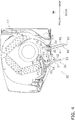
- the first upper flap 40, the second upper flap 50, and the lower flap 60 of the airflow direction switching mechanism 30 are controlled by the control unit 80, to be described later, to have postures depicted in FIG. 4 .
- the first upper flap 40, the second upper flap 50, and the lower flap 60 take the postures depicted in FIG. 4 , there is generated an airflow which goes backward (toward the wall WL provided with the air conditioning indoor unit 10) from the blow-out port 27.
- the lower flap 60 rotates to dispose the first end 63 in the rear of the second end 64 so that the lower flap upper surface 61 inclines with respect to the vertical plane in a state disposing its upper end side (the second end 64 side) forward.
- the second upper flap 50 rotates to dispose the first end 53 in the rear of the second end 54 so that the second upper flap upper surface 51 inclines with respect to the vertical plane in a state disposing its upper end side (the second end 54 side) forward.
- the first upper flap 40 rotates to dispose the first end 43 in the rear of the second end 44 so that the first upper flap upper surface 41 inclines with respect to the vertical plane in a state disposing its upper end side (the second end 44 side) forward.
- the lower flap lower surface 62 preferably has a recess 66 positioned adjacent to the second end 64.
- the lower flap 60 is formed to allow the recess 66 provided in the lower flap lower surface 62 to receive the lower edge 27b of the blow-out port 27 when air blows out in the second direction. In comparison to a case where the lower flap lower surface 62 has no recess 66, this configuration enables the first end 63 of the lower flap 60 to move further backward to allow the air to flow along the wall WL from a higher position.
- postures of the first upper flap 40, the second upper flap 50, and the lower flap 60 when air blows out in the second direction are merely examples herein.
- the postures of the first upper flap 40, the second upper flap 50, and the lower flap 60 may be appropriately determined to cause the airflow direction of the blow-out air from the blow-out port 27 to be the second direction (vertically downward or substantially vertically downward).
- the postures of the first upper flap 40, the second upper flap 50, and the lower flap 60 may alternatively be determined such that the first upper flap upper surface 41, the second upper flap upper surface 51, and the lower flap upper surface 61 become substantially vertical planes when air blows out in the second direction.
- the floor temperature sensor 70 is an exemplary temperature unevenness detection sensor configured to detect temperature unevenness in the air conditioning target space RS.
- the floor temperature sensor 70 detects a floor temperature in the room.
- the floor temperature sensor 70 may be configured as a sensor adopting any one of various detection methods.
- the floor temperature sensor 70 is a thermopile array sensor.
- the floor temperature sensor 70 may be provided on the bottom surface 11f of the casing 11, for example (see FIG. 1 ).
- the floor temperature sensor 70 detects a floor temperature for each of areas in the air conditioning target space RS. For example, the floor temperature sensor 70 divides the floor of the air conditioning target space RS into 8 ⁇ 8 areas and detects a temperature in each of the areas.
- the floor temperature sensor 70 detects a temperature of a floor surface adjacent to the wall WL provided with the air conditioning indoor unit 10, as a temperature of a position below the air conditioning indoor unit 10.
- the floor temperature sensor 70 detects a temperature of a floor surface distant from the wall WL provided with the air conditioning indoor unit 10, as a temperature of a position distant from the wall WL in the air conditioning target space RS.
- the floor temperature sensor 70 is an example of the first temperature sensor and the second temperature sensor.
- the floor temperature sensor 70 functions as the first temperature sensor and the second temperature sensor, although the present invention should not be limited to such a configuration.
- the floor temperature sensor 70 may alternatively include a first floor temperature sensor functioning as the first temperature sensor, and a second floor temperature sensor provided separately from the first floor temperature sensor and functioning as the second temperature sensor.
- the space temperature sensor 71 detects a temperature of the air conditioning target space RS.
- the space temperature sensor 71 is disposed adjacent to the top intake port 25 or the like and detects, as a temperature of the air conditioning target space RS, a temperature of air introduced into the air conditioning indoor unit 10.
- the disposition of the space temperature sensor 71 disclosed in this embodiment is merely an example, and the space temperature sensor 71 may alternatively be disposed at a different position where a representative temperature of the air conditioning target space RS can be detected.
- the space humidity sensor 72 detects a humidity of the air conditioning target space RS.
- the space humidity sensor 72 is disposed adjacent to the top intake port 25 or the like and detects, as a humidity of the air conditioning target space RS, a humidity of air introduced into the air conditioning indoor unit 10.
- the disposition of the space humidity sensor 72 disclosed in this embodiment is merely an example, and the space humidity sensor 72 may alternatively be disposed at a different position where a representative humidity of the air conditioning target space RS can be detected.
- the control unit 80 mainly includes a CPU (not depicted) and a memory (not depicted). The control unit 80 executes a program stored in the memory to control operation of the air conditioning indoor unit 10.
- the control unit 80 is electrically connected to the indoor fan 14 and the airflow direction switching mechanism 30 (the flap driving motor of the airflow direction switching mechanism 30) of the air conditioning indoor unit 10.
- the control unit 80 is also electrically connected to various sensors including the floor temperature sensor 70, the space temperature sensor 71, and the space humidity sensor 72 of the air conditioning indoor unit 10.
- the control unit 80 is further electrically connected to a control unit (not depicted) included in the air conditioning outdoor unit that configures the air conditioner together with the air conditioning indoor unit 10.
- the control unit 80 is configured to be communicable with a remote controller (not depicted) operated by a user of the air conditioner to command the air conditioner.
- the control unit 80 controls operation of the indoor fan 14, the airflow direction switching mechanism 30, and the like in accordance with results of measurement by the various sensors, signals transmitted from the control unit of the air conditioning outdoor unit, commands by the user of the air conditioner transmitted via the remote controller, and the like.
- control on operation of the air conditioning indoor unit 10 during the circulation mode cooling operation is mainly described among various control on operation of the air conditioning indoor unit 10 by the control unit 80.
- the control unit 80 includes, as functional units particularly relating to control on operation of the air conditioning indoor unit 10 during the circulation mode cooling operation, a switching mechanism control unit 81, a control permission unit 82, a fan control unit 83, a temperature unevenness detector 84, and a temperature unevenness presumer 85.
- the switching mechanism control unit 81 controls operation of the airflow direction switching mechanism 30 to switch the airflow direction of the blow-out air from the blow-out port 27.
- the switching mechanism control unit 81 controls operation of the airflow direction switching mechanism 30 to switch the airflow direction of the blow-out air from the blow-out port 27 as designated by the user of the air conditioner with use of the remote controller or in accordance with an operating mode or an airflow mode of the air conditioner designated by the user of the air conditioner with use of the remote controller.
- the air conditioner has operating modes including an automatic mode, a cooling mode, a dehumidifying mode, a heating mode, a ventilating mode, and the like.
- the automatic mode corresponds to an operating mode in which the control unit 80 automatically selects an operation content in accordance with a temperature, a humidity, or the like of the air conditioning target space RS.
- Airflow modes relate to aspects of sending the blow-out air out of the blow-out port 27, and the circulation mode mentioned earlier corresponds to one of the airflow modes.
- the switching mechanism control unit 81 When being in the circulation mode cooling operation, the user of the air conditioner selects the automatic mode, the cooling mode, or the dehumidifying mode as an operating mode of the air conditioner, as well as the circulation mode as an airflow mode, for execution of cooling operation or dehumidifying operation by the air conditioner.
- the switching mechanism control unit 81 normally controls operation of the airflow direction switching mechanism 30 to cause the air conditioning indoor unit 10 to send the blow-out air in the first direction.
- the switching mechanism control unit 81 controls operation of the airflow direction switching mechanism 30 so that the blow-out air temporarily blows out in the second direction when temperature unevenness is detected or presumed in the air conditioning target space RS while the air conditioning indoor unit 10 is sending the blow-out air in the first direction. More specifically, the switching mechanism control unit 81 controls the operation of the airflow direction switching mechanism 30 so that the blow-out air temporarily blows out in the second direction in accordance with a result of detection by the temperature unevenness detector 84 to be described later while the air conditioning indoor unit 10 is sending the blow-out air in the first direction.
- the switching mechanism control unit 81 controls the operation of the airflow direction switching mechanism 30 so that the blow-out air temporarily blows out in the second direction in accordance with a result of presumption by the temperature unevenness presumer 85 to be described later while the air conditioning indoor unit 10 is sending the blow-out air in the first direction.
- the control permission unit 82 is a functional unit configured to permit the switching mechanism control unit 81 to control operation of the airflow direction switching mechanism 30. Conversely, the control permission unit 82 is a functional unit configured to prohibit the switching mechanism control unit 81 from controlling operation of the airflow direction switching mechanism 30. Particularly, the control permission unit 82 permits the switching mechanism control unit 81 to control operation of the airflow direction switching mechanism 30 so as to switch the airflow direction of the blow-out air to the second direction while the air conditioning indoor unit 10 is sending air in the first direction.
- the switching mechanism control unit 81 controls the operation of the airflow direction switching mechanism 30 in accordance with a result of detection by the temperature unevenness detector 84 or a result of presumption by the temperature unevenness presumer 85 while the air conditioning indoor unit 10 is sending the blow-out air in the first direction.
- the switching mechanism control unit 81 cannot control the operation of the airflow direction switching mechanism 30 to switch the airflow direction of the blow-out air from the first direction to the second direction even if the temperature unevenness is detected or presumed in the air conditioning target space RS.
- control permission unit 82 permits the switching mechanism control unit 81 to control operation of the airflow direction switching mechanism 30.
- the fan control unit 83 controls to operate or stop the indoor fan 14, and also controls an airflow volume of the indoor fan 14 (number of rotations of a fan motor).
- the fan control unit 83 is an example of the airflow volume control unit.
- the fan control unit 83 controls operation of the indoor fan 14 to switch an airflow volume of the blow-out air from the blow-out port 27 as designated by the user of the air conditioner with use of the remote controller or in accordance with an operating mode or an airflow mode of the air conditioner designated by the user of the air conditioner with use of the remote controller.
- the fan control unit 83 decreases the airflow volume of the indoor fan 14, in comparison to the airflow volume of the indoor fan 14 at the time when the blow-out air blowing out in the first direction or the second direction, while the airflow direction switching mechanism 30 is switching the airflow direction of the blow-out air from the first direction to the second direction or from the second direction to the first direction during the circulation mode cooling operation.
- the fan control unit 83 controls the airflow volume of the indoor fan 14 to a minimum level while the airflow direction switching mechanism 30 is switching the airflow direction of the blow-out air from the first direction to the second direction or from the second direction to the first direction during the circulation mode cooling operation.
- the fan control unit 83 decreases the airflow volume of the indoor fan 14 at the time when the blow-out air blowing out in the second direction in comparison to the airflow volume of the indoor fan 14 at the time when the blow-out air blowing out in the first direction.
- the fan control unit 83 controls the airflow volume of the indoor fan 14 in this manner during the circulation mode cooling operation, to prevent the airflow from directly hitting a person in the air conditioning target space RS for reducing deterioration in comfort.
- the temperature unevenness detector 84 detects temperature unevenness in the air conditioning target space RS in accordance with a result of measurement by the floor temperature sensor 70.
- the temperature unevenness detector 84 detects the temperature unevenness in the air conditioning target space RS at least during the circulation mode cooling operation.
- the temperature unevenness detector 84 detects the temperature unevenness in the air conditioning target space RS in accordance with a result of comparison between a temperature at a near side and a temperature at a far side transmitted from the floor temperature sensor 70.
- the temperature at the near side indicates a measurement value of the temperature of the position below the air conditioning indoor unit 10 (temperature of the floor surface adjacent to the wall WL provided with the air conditioning indoor unit 10) measured by the floor temperature sensor 70.
- the temperature at the far side indicates a measurement value of the temperature of the position distant from the wall WL in the air conditioning target space RS (temperature of the floor surface distant from the wall WL provided with the air conditioning indoor unit 10) measured by the floor temperature sensor 70.
- the temperature unevenness detector 84 detects the temperature unevenness in the air conditioning target space RS when a difference between the temperature at the near side and the temperature at the far side is equal to or more than a predetermined value, more specifically, when the temperature at the near side is higher than the temperature at the far side by at least the predetermined value.
- the temperature unevenness detector 84 may detect the temperature unevenness in the air conditioning target space RS in accordance with a result of comparison between the temperature at the near side and the temperature at the far side at a certain moment.
- the temperature unevenness detector 84 may alternatively detect the temperature unevenness in the air conditioning target space RS in accordance with a result of comparison between the temperature at the near side and the temperature at the far side during a certain period (e.g. one minute).
- the temperature unevenness detector 84 may detect the temperature unevenness in the air conditioning target space RS when the temperature at the near side is higher than the temperature at the far side by at least the predetermined value for the certain period.
- the temperature unevenness presumer 85 presumes occurrence of the temperature unevenness in the air conditioning target space RS.
- the temperature unevenness detector 84 presumes the occurrence of the temperature unevenness in the air conditioning target space RS at least during the circulation mode cooling operation.
- the temperature unevenness presumer 85 presumes the occurrence of the temperature unevenness in the air conditioning target space when a period in which the blow-out air continuously blows out in the first direction exceeds a predetermined period in the circulation mode cooling operation.
- the following series of processing starts when the user of the air conditioner selects, with use of the remote controller, the automatic mode, the cooling mode, or the dehumidifying mode as an operating mode of the air conditioner, as well as the circulation mode as an airflow mode and then commands start of the air conditioner, and the control unit 80 selects the cooling operation or the dehumidifying operation if the automatic mode is selected as the operating mode.
- the following description does not take into consideration a case where the user of the air conditioner halfway changes the operating mode or the airflow mode.
- step S1 the switching mechanism control unit 81 controls the operation of the airflow direction switching mechanism 30 to direct the airflow direction of the blow-out air from the blow-out port 27 to the first direction. Specifically, the switching mechanism control unit 81 commands the flap driving motor (not depicted) of the airflow direction switching mechanism 30 to change the postures of the first upper flap 40, the second upper flap 50, and the lower flap 60 to the postures for blowing out air in the first direction.
- step S2 it is determined whether an initial switching period has elapsed after the blow-out air starts blowing out in the first direction.
- the initial switching period is set preliminarily.
- the initial switching period should not be limited and is exemplarily set to ten minutes.
- the flow proceeds to step S3 when it is determined that the initial switching period has elapsed after the blow-out air starts flowing in the first direction.
- Step S2 is executed repeatedly until it is determined that the initial switching period has elapsed after the blow-out air starts flowing in the first direction.
- the control permission unit 82 is configured to permit the switching mechanism control unit 81 to control the operation of the airflow direction switching mechanism 30 so that the blow-out air blows out in the second direction in a case where a continuous operation period after the air conditioning indoor unit 10 starts sending the blow-out air in the first direction firstly after the circulation mode cooling operation starts exceeds the initial switching period.
- the control permission unit 82 thus permits the switching mechanism control unit 81 to control the operation of the airflow direction switching mechanism 30 so that the blow-out air blows out in the second direction.
- the temperature unevenness presumer 85 is configured to presume the occurrence of the temperature unevenness in the air conditioning target space RS in a case where a period in which the blow-out air continuously blows out in the first direction exceeds the initial switching period. In step S3, the temperature unevenness presumer 85 thus presumes the occurrence of the temperature unevenness in the air conditioning target space RS.
- step S4 the switching mechanism control unit 81 controls the operation of the airflow direction switching mechanism 30 so that the blow-out air blows out in the second direction because the control permission unit 82 permits the switching mechanism control unit 81 to control the operation of the airflow direction switching mechanism 30 and the temperature unevenness is detected or presumed in the air conditioning target space RS.
- the switching mechanism control unit 81 commands the flap driving motor (not depicted) of the airflow direction switching mechanism 30 to change the postures of the first upper flap 40, the second upper flap 50, and the lower flap 60 of the airflow direction switching mechanism 30 to the postures for blowing out air in the second direction.
- step S5 it is determined whether a second direction blow-out set period has elapsed after the blow-out air starts blowing out in the second direction.
- the second direction blow-out set period is set preliminarily for relief of the temperature unevenness in the air conditioning target space RS.
- the second direction blow-out set period should not be limited and is exemplarily set to two minutes.
- Step S6 when it is determined that the second direction blow-out set period has elapsed after the blow-out air starts blowing out in the second direction.
- Step S5 is executed repeatedly until it is determined that the second direction blow-out set period has elapsed after the blow-out air starts blowing out in the second direction.
- step S6 the switching mechanism control unit 81 controls the operation of the airflow direction switching mechanism 30 to blow out the blow-out air in the first direction. Specifically, the switching mechanism control unit 81 commands the flap driving motor (not depicted) of the airflow direction switching mechanism 30 to change the postures of the first upper flap 40, the second upper flap 50, and the lower flap 60 to the postures for blowing out air in the first direction.
- the control permission unit 82 prohibits (cancels control permission for) the switching mechanism control unit 81 from controlling the operation of the airflow direction switching mechanism 30 to blow out the blow-out air in the second direction.
- step S7 it is determined whether the air conditioning target space RS satisfies a predetermined condition continuously for a first predetermined period.
- the predetermined condition in this case is that a temperature detected by the space temperature sensor 71 is equal to or less than a predetermined temperature and a humidity detected by the space humidity sensor is equal to or less than a predetermined humidity.
- the predetermined temperature and the predetermined humidity preferably have values that should satisfy that comfort of the user of the air conditioner.
- step S7 it is determined whether the temperature detected by the space temperature sensor 71 is equal to or less than a set temperature input with use of the remote controller and the humidity detected by the space humidity sensor 72 is equal to or less than 70% continuously for at least 60 minutes, for example.
- step S8 when it is determined that the air conditioning target space RS satisfies the predetermined condition continuously for the first predetermined period. Determination in step S7 is executed repeatedly until it is determined that the air conditioning target space RS satisfies the predetermined condition continuously for the first predetermined period.
- the control permission unit 82 is configured to permit the switching mechanism control unit 81 to control the operation of the airflow direction switching mechanism 30 so as to blow out the blow-out air in the second direction when the temperature detected by the space temperature sensor 71 is equal to or less than the predetermined temperature and the humidity detected by the space humidity sensor 72 is equal to or less than the predetermined humidity continuously for at least the first predetermined period during the circulation mode cooling operation.
- the control permission unit 82 thus permits the switching mechanism control unit 81 to control operation of the airflow direction switching mechanism 30 so as to blow out the blow-out air in the second direction.
- the temperature unevenness detector 84 detects the temperature unevenness in the air conditioning target space RS in accordance with a result of comparison between the temperature at the near side and the temperature at the far side transmitted from the floor temperature sensor 70.
- the temperature at the near side indicates the measurement value of the temperature of the position below the air conditioning indoor unit 10 measured by the floor temperature sensor 70
- the temperature at the far side indicates the measurement value of the temperature of the position distant from the wall WL in the air conditioning target space RS measured by the floor temperature sensor 70.
- the temperature unevenness detector 84 determines whether the temperature at the near side is higher than the temperature at the far side by at least the predetermined value.
- the temperature unevenness detector 84 detects the temperature unevenness in the air conditioning target space RS when the temperature at the near side is higher than the temperature at the far side by at least the predetermined value (e.g. at a certain moment or for a certain period) (step S10), and the flow then returns to step S4. Processing in step S4 has been described earlier and will not be described repeatedly. The flow proceeds to step S11 when the temperature at the front position is not higher than the temperature at the back position by at least the predetermined value.
- the predetermined value e.g. at a certain moment or for a certain period
- step S 11 it is determined whether a period for which the blow-out air blows out in the first direction continuously (a period after the airflow direction of the blow-out air is switched to the first direction most recently) exceeds a second predetermined period.
- the second predetermined period is set preliminarily.
- the second predetermined period should not be limited and is exemplarily set to 90 minutes.
- the flow proceeds to step S12 when it is determined that the blow-out air blows out in the first direction continuously for a period exceeding the second predetermined period.
- the flow returns to step S7 if it is determined that a period for which the blow-out air blows out in the first direction continuously is less than the second predetermined period.
- control permission unit 82 prohibits (cancels control permission for) the switching mechanism control unit 81 from controlling the operation of the airflow direction switching mechanism 30 to blow out the blow-out air in the second direction.
- the temperature unevenness presumer 85 is configured to presume the occurrence of temperature unevenness in the air conditioning target space RS when a period for which the blow-out air blows out in the first direction continuously exceeds the second predetermined period unless the step S3 is in process. In step S12, the temperature unevenness presumer 85 thus presumes the occurrence of the temperature unevenness in the air conditioning target space RS. The flow then proceeds to step S4. Processing in step S4 has been described earlier and will not be described repeatedly.
- the switching of the airflow direction of the blow-out air described with reference to FIG. 5 is an example of switching of the airflow direction of the blow-out air during the circulation mode cooling operation, and the present invention should not be limited to this example.
- the switching of the airflow direction of the blow-out air during the circulation mode cooling operation may alternatively be designed such that the steps S2 to S6 are omitted and the flow proceeds to step S7 after the execution of processing in step S1 depicted in FIG. 5 .
- the air conditioning indoor unit 10 includes the casing 11, the indoor heat exchanger 13 as an exemplary heat exchanger, the indoor fan 14 as an exemplary fan, the airflow direction switching mechanism 30, and the switching mechanism control unit 81.
- the casing 11 has the top intake port 25, the bottom intake port 26, and the blow-out port 27.
- the indoor heat exchanger 13 exchanges heat with air sucked through the top intake port 25 and the bottom intake port 26 to draw the heat from the air.
- the indoor fan 14 sends the air exchanged heat at the indoor heat exchanger 13 out of the blow-out port 27.
- the airflow direction switching mechanism 30 switches the airflow direction of the blow-out air from the blow-out port 27 at least between the first direction and the second direction.
- the first direction is horizontal or substantially horizontal direction.
- the second direction is vertically downward or substantially vertically downward direction.
- the switching mechanism control unit 81 controls operation of the airflow direction switching mechanism 30 so that the blow-out air temporarily blows out in the second direction when occurrence of temperature unevenness is detected or presumed in the air conditioning target space RS while the blow-out air is flowing in the first direction.
- the air conditioning indoor unit 10 blows out air in the second direction in a case where temperature unevenness is detected or presumed in the air conditioning target space RS when cooling (including dehumidifying) is performed while blowing out air in the first direction.
- This configuration achieves supply of conditioned air to an area vertically below the air conditioning indoor unit 10, where the blow-out air blowing out in the first direction is unlikely to reach, to relieve the temperature unevenness in the air conditioning target space RS and provide the comfortable air conditioning target space RS.
- the air conditioning indoor unit 10 includes the floor temperature sensor 70 and the temperature unevenness detector 84.
- the floor temperature sensor 70 is an example of a temperature unevenness detection sensor configured to detect the temperature unevenness.
- the temperature unevenness detector 84 detects the temperature unevenness in the air conditioning target space RS in accordance with a result of measurement by the floor temperature sensor 70.
- the switching mechanism control unit 81 controls the operation of the airflow direction switching mechanism 30 so that the blow-out air temporarily blows out in the second direction in accordance with a result of detection by the temperature unevenness detector 84 while the blow-out air blowing out in the first direction.
- the air conditioning indoor unit 10 can accurately detect the temperature unevenness in accordance with the result of measurement by the floor temperature sensor 70 and relieve the temperature unevenness through control on the airflow direction of the blow-out air.
- the air conditioning indoor unit 10 is of the wall-mounted type.
- the floor temperature sensor 70 includes the first temperature sensor configured to measure a temperature of the position below the air conditioning indoor unit 10. In other words, the floor temperature sensor 70 functions as the first temperature sensor configured to measure the temperature of the position below the air conditioning indoor unit 10.
- the temperature unevenness is detected in accordance with a result of measurement by the first temperature sensor that measures the temperature of the position below the air conditioning indoor unit 10 of the wall-mounted type to facilitate accurate detection of the temperature unevenness without missing out it.
- the floor temperature sensor 70 includes the second temperature sensor that measures a temperature of the position, which is distant from the wall WL on which the air conditioning indoor unit 10 is installed, in the air conditioning target space RS.
- the floor temperature sensor 70 functions as the second temperature sensor that measures the temperature of the position, which is distant from the wall WL on which the air conditioning indoor unit 10 is installed, in the air conditioning target space RS.
- the temperature unevenness detector 84 detects the temperature unevenness in the air conditioning target space RS in accordance with a result of comparison between a measurement value (temperature at the near side) of the floor temperature sensor 70 functioning as the first temperature sensor and a measurement value (temperature at the far side) of the floor temperature sensor 70 functioning as the second temperature sensor.
- the air conditioning indoor unit 10 detects the temperature unevenness in accordance with measurement results of the temperature of the position, which is distant from the wall WL on which the air conditioning indoor unit 10 is installed, in the air conditioning target space RS and the temperature of the position below the air conditioning indoor unit 10, to facilitate accurate detection of the temperature unevenness without missing out it.
- the air conditioning indoor unit 10 includes the temperature unevenness presumer 85.
- the temperature unevenness presumer 85 presumes occurrence of temperature unevenness in the air conditioning target space RS in a case where the period in which the blow-out air continuously blows out in the first direction exceeds the first period.
- the switching mechanism control unit 81 controls the operation of the airflow direction switching mechanism 30 so that the blow-out air temporarily blows out in the second direction in accordance with a result of presumption by the temperature unevenness presumer 85 while the blow-out air blowing out in the first direction.
- the temperature unevenness presumer 85 presumes the occurrence of temperature unevenness in the air conditioning target space RS when the blow-out air blows out in the first direction continuously for the period exceeding the initial switching period immediately after the start of circulation cooling operation (see FIG. 5 ). At timing other than the above, the temperature unevenness presumer 85 presumes the occurrence of temperature unevenness in the air conditioning target space RS when the blow-out air flows in the first direction continuously for a period exceeding the second predetermined period (see FIG. 5 ).
- the air conditioning indoor unit 10 can appropriately presume occurrence of the temperature unevenness based on a feature that the temperature unevenness is likely to occur at a position immediately below the air conditioning indoor unit 10 when air blows out in the first direction, to suppress the occurrence of the temperature unevenness as well as to relieve the temperature unevenness.
- the air conditioning indoor unit 10 includes the floor temperature sensor 70 functioning as the temperature unevenness detection sensor.
- temperature unevenness may occur at a position where the floor temperature sensor 70 can hardly detect it.
- occurrence of the temperature unevenness is presumed when the blow-out air blows out in the first direction continuously for a long period. This configuration can thus relieve the temperature unevenness in the air conditioning target space RS, even if there is a difficulty for the sensor to detect the temperature unevenness.
- the air conditioning indoor unit 10 includes the space temperature sensor 71, the space humidity sensor 72, and the control permission unit 82.
- the space temperature sensor 71 detects a temperature of the air conditioning target space RS.
- the space humidity sensor 72 detects a humidity of the air conditioning target space RS.
- the control permission unit 82 permits the switching mechanism control unit 81 to control the operation of the airflow direction switching mechanism 30.
- the control permission unit 82 permits the switching mechanism control unit 81 to control the operation of the airflow direction switching mechanism 30 so that the blow-out air blows out in the second direction in a case where a condition that the temperature detected by the space temperature sensor 71 is equal to or less than the predetermined temperature and the humidity detected by the space humidity sensor 72 is equal to or less than the predetermined humidity continues for at least the first predetermined period.
- the air conditioning indoor unit 10 prioritizes to blow out air in the first direction to facilitate generation of a circulating airflow in the air conditioning target space RS until the temperature and the humidity of the air conditioning target space RS satisfy predetermined conditions. This configuration can thus further improve in comfort through relief of temperature unevenness after initially securing comfort in the entire air conditioning target space RS.
- control permission unit 82 permits the switching mechanism control unit 81 to control the operation of the airflow direction switching mechanism 30 so that the blow-out air blows out in the second direction in a case where the continuous operation period after the air conditioning indoor unit 10 starts blowing out the blow-out air in the first direction firstly after starting its operation exceeds the initial switching period.
- the air conditioning indoor unit 10 permits the blow-out air to blow out in the second direction immediately after the start of the operation when temperature unevenness is particularly likely to occur, regardless of whether the temperature and the humidity in the air conditioning target space RS satisfy the predetermined conditions. This configuration facilitates relief of the temperature unevenness immediately after the start of the operation.
- the air conditioning indoor unit 10 includes the fan control unit 83 as an exemplary airflow volume control unit configured to control the airflow volume of the indoor fan 14.
- the airflow direction switching mechanism 30 switches the airflow direction of the blow-out air from the first direction to the second direction or from the second direction to the first direction by continuously changing the air flow direction of the blow-out air.
- the fan control unit 83 decreases the airflow volume of the indoor fan 14, in comparison to the airflow volume of the indoor fan 14 at the time when the blow-out air blowing out in the first direction or the second direction, while the airflow direction switching mechanism 30 is switching the airflow direction of the blow-out air from the first direction to the second direction or from the second direction to the first direction.
- the air conditioning indoor unit 10 suppresses that the airflow directly hits a person in the air conditioning target space RS so as not to deteriorate comfort.
- the fan control unit 83 decreases the airflow volume of the indoor fan 14 at the time when the blow-out air blowing out in the second direction in comparison to the airflow volume of the indoor fan 14 at the time when the blow-out air blowing out in the first direction.
- the air conditioning indoor unit 10 decreases the airflow volume when the air blows out downward, to facilitate suppression of the airflow directly hitting a person in the air conditioning target space RS for reducing deterioration in comfort.
- the temperature unevenness detector 84 detects the temperature unevenness in the air conditioning target space RS in accordance with a result of comparison between the temperature at the near side and the temperature at the far side transmitted from the floor temperature sensor 70.
- the method of detection by the temperature unevenness detector 84 is not limited to this method.
- the temperature unevenness detector 84 may alternatively detect the temperature unevenness in the air conditioning target space RS in accordance with time change of the temperature measured by the first temperature sensor (in other words, the temperature at the near side transmitted from the floor temperature sensor 70). More specifically, the temperature unevenness detector 84 may detect the temperature unevenness in the air conditioning target space RS when the temperature measured by the first temperature sensor gradually increases (despite no change in a set temperature input with use of the remote controller). This enables detection of temperature unevenness by means of a relatively simple configuration and relieves the temperature unevenness through control on the airflow direction of the blow-out air.
- Temperature unevenness in the air conditioning target space RS may occur due to solar radiation.
- the air conditioning target space RS may have temperature unevenness when the floor surface is warmed by sunlight coming through a window in the wall WL provided with the air conditioning indoor unit 10 or when the wall WL provided with the air conditioning indoor unit 10 is warmed by sunlight.
- the air conditioning target space RS is thus likely to have temperature unevenness particularly during daytime.
- the switching of the airflow direction of the blow-out air from the first direction to the second direction during the circulation mode cooling operation may alternatively be executed only during daytime.
- the control permission unit 82 may always prohibit the switching mechanism control unit 81 from controlling the operation of the airflow direction switching mechanism 30 to send the blow-out air in the second direction during nighttime.
- the above embodiment merely exemplifies, and thus should not limit, the configuration of the airflow direction switching mechanism 30.
- the airflow direction switching mechanism may alternatively be configured to switch the airflow direction of the blow-out air from the blow-out port 27 between the first direction and the second direction with use of two or fewer flaps, or three or more flaps.
- the casing 11 may alternatively be provided with two or more blow-out ports, such that the air conditioning indoor unit is configured to blow out air out of different blow-out ports between the case where the air blows out in the first direction and the case where the air blows out in the second direction.
- the airflow direction switching mechanism may alternatively adjust the airflow direction with use of the different flaps between the case where the air blows out in the first direction and the case where the air blows out in the second direction.
- the switching mechanism control unit 81 controls the operation of the airflow direction switching mechanism 30 so that the blow-out air temporarily blows out in the second direction in each of the case where temperature unevenness is detected in the air conditioning target space RS and the case where occurrence of temperature unevenness is presumed in the air conditioning target space RS while the blow-out air is blowing out in the first direction.
- the air conditioning indoor unit may alternatively include no temperature unevenness presumer 85 and the switching mechanism control unit 81 may control operation of the airflow direction switching mechanism 30 so that the blow-out air temporarily blows out in the second direction only in the case where the temperature unevenness is detected in the air conditioning target space RS while the blow-out air is blowing out in the first direction.
- the air conditioning indoor unit may still alternatively include no temperature unevenness detector 84 and the switching mechanism control unit 81 may control the operation of the airflow direction switching mechanism 30 so that the blow-out air temporarily blows out in the second direction only in the case where the occurrence of the temperature unevenness is presumed in the air conditioning target space RS while the blow-out air is blowing out in the first direction.
- the airflow direction switching mechanism 30 In order to suppress the occurrence of the temperature unevenness more reliably, it is preferable to control the operation of the airflow direction switching mechanism 30 so that the blow-out air blows out in the second direction in each of the case where temperature unevenness is detected in the air conditioning target space RS and the case where occurrence of temperature unevenness is presumed in the air conditioning target space RS.
- the present invention is useful because of wide applicability to an air conditioning indoor unit.
Landscapes
- Engineering & Computer Science (AREA)
- Chemical & Material Sciences (AREA)
- Combustion & Propulsion (AREA)
- Mechanical Engineering (AREA)
- General Engineering & Computer Science (AREA)
- Physics & Mathematics (AREA)
- Fluid Mechanics (AREA)
- Air Conditioning Control Device (AREA)
Abstract
Description
- The present invention relates to an air conditioning indoor unit.
- As disclosed in Patent Literature 1 (
JP 2013-076530 A - However, such air blowing out horizontally or substantially horizontally from the air conditioning indoor unit is unlikely to reach an area vertically below the air conditioning indoor unit. As a result, temperature unevenness may be caused in the air conditioning target space and it may be further required to improve the comfort.
- An object of the present invention is to provide an air conditioning indoor unit configured to facilitate relief of temperature unevenness in an air conditioning target space during cooling operation to achieve the highly comfortable air conditioning target space.
- An air conditioning indoor unit according to a first aspect of the present invention includes a casing, a heat exchanger, a fan, an airflow direction switching mechanism, and a switching mechanism control unit. The casing has an intake port and a blow-out port. The heat exchanger exchanges heat with air sucked through the intake port to draw the heat from the air. The fan sends the air exchanged heat at the heat exchanger out of the blow-out port. The airflow direction switching mechanism switches an airflow direction of blow-out air from the blow-out port at least between a first direction and a second direction. The first direction is horizontal or substantially horizontal direction. The second direction is vertically downward or substantially vertically downward direction. The switching mechanism control unit controls operation of the airflow direction switching mechanism so that the blow-out air temporarily blows out in the second direction when temperature unevenness is detected or presumed in the air conditioning target space while the blow-out air is blowing out in the first direction.
- The air conditioning indoor unit according to the first aspect of the present invention blows out air in the second direction (vertically downward or substantially vertically downward) in a case where temperature unevenness is detected or presumed in the air conditioning target space when cooling (including dehumidifying) is performed while blowing out air in the first direction (horizontally or substantially horizontally). This configuration achieves supply of conditioned air to an area vertically below the air conditioning indoor unit, where the blow-out air blowing out in the first direction is unlikely to reach, to relieve the temperature unevenness in the air conditioning target space and provide the comfortable air conditioning target space.
- An air conditioning indoor unit according to a second aspect of the present invention is the air conditioning indoor unit according to the first aspect and further includes a temperature unevenness detection sensor detecting the temperature unevenness and a temperature unevenness detector. The temperature unevenness detector detects the temperature unevenness in the air conditioning target space in accordance with a result of measurement by the temperature unevenness detection sensor. The switching mechanism control unit controls the operation of the airflow direction switching mechanism so that the blow-out air temporarily blows out in the second direction in accordance with a result of detection by the temperature unevenness detector while the blow-out air blowing out in the first direction.
- The air conditioning indoor unit according to the second aspect of the present invention can accurately detect the temperature unevenness in accordance with the result of measurement by the sensor and relieve the temperature unevenness through control on the airflow direction of the blow-out air.
- An air conditioning indoor unit according to a third aspect of the present invention is the air conditioning indoor unit according to the second aspect and is of a wall-mounted type. The temperature unevenness detection sensor includes a first temperature sensor. The first temperature sensor measures a temperature of a position below the air conditioning indoor unit.
- The air conditioning indoor unit according to the third aspect of the present invention detects the temperature unevenness in accordance with a result of measurement by the first temperature sensor that measures the temperature of the position below the air conditioning indoor unit of the wall-mounted type to facilitate accurate detection of the temperature unevenness without missing out it.
- An air conditioning indoor unit according to a fourth aspect of the present invention is the air conditioning indoor unit according to the third aspect, and the temperature unevenness detection sensor further includes a second temperature sensor. The second temperature sensor measures a temperature of a position, which is distant from a wall on which the air conditioning indoor unit is installed, in the air conditioning target space. The temperature unevenness detector detects the temperature unevenness in the air conditioning target space in accordance with a result of comparison between a measurement value of the first temperature sensor and a measurement value of the second temperature sensor.
- The air conditioning indoor unit according to the fourth aspect of the present invention detects the temperature unevenness in accordance with measurement results of the temperature of the position, which is distant from the wall on which the air conditioning indoor unit is installed, in the air conditioning target space and the temperature of the position below the air conditioning indoor unit, to facilitate accurate detection of the temperature unevenness without missing out it.
- An air conditioning indoor unit according to a fifth aspect of the present invention is the air conditioning indoor unit according to the third aspect, and the temperature unevenness detector detects the temperature unevenness in the air conditioning target space in accordance with time change of the temperature measured by the first temperature sensor.
- The air conditioning indoor unit according to the fifth aspect of the present invention detects the temperature unevenness by means of only the first temperature sensor that measures the temperature of the position below the air conditioning indoor unit of the wall-mounted type, in other words, by means of a relatively simple configuration, and relieves the temperature unevenness through control on the airflow direction of the blow-out air.
- An air conditioning indoor unit according to a sixth aspect of the present invention is the air conditioning indoor unit according to any one of the first to fifth aspects, and further includes a temperature unevenness presumer. The temperature unevenness presumer presumes occurrence of the temperature unevenness in the air conditioning target space in a case where a period in which the blow-out air continuously blows out in the first direction exceeds a first period. The switching mechanism control unit controls the operation of the airflow direction switching mechanism so that the blow-out air temporarily blows out in the second direction in accordance with a result of presumption by the temperature unevenness presumer while the blow-out air blowing out in the first direction.
- The air conditioning indoor unit according to the sixth aspect of the present invention appropriately presumes occurrence of the temperature unevenness based on a feature that the temperature unevenness is likely to occur at a position immediately below the air conditioning indoor unit when air blows out in the first direction, to suppress the occurrence of the temperature unevenness as well as to relieve the temperature unevenness.
- Even in the case where the air conditioning indoor unit includes the temperature unevenness detection sensor, under some condition, temperature unevenness may occur at a position where the temperature unevenness detection sensor has difficulty in measuring. However, in this aspect, the occurrence of temperature unevenness is presumed when the blow-out air blows out in the first direction continuously for a long period. This configuration can thus relieve the temperature unevenness in the air conditioning target space, even if there is a difficulty for the sensor to detect the temperature unevenness.
- An air conditioning indoor unit according to a seventh aspect of the present invention is the air conditioning indoor unit according to any one of the first to sixth aspects, and further includes a space temperature sensor, a space humidity sensor, and a control permission unit. The space temperature sensor detects a temperature of the air conditioning target space. The space humidity sensor detects a humidity of the air conditioning target space. The control permission unit permits the switching mechanism control unit to control the operation of the airflow direction switching mechanism. The control permission unit permits the switching mechanism control unit to control the operation of the airflow direction switching mechanism so that the blow-out air blows out in the second direction in a case where a condition that the temperature detected by the space temperature sensor is equal to or less than a predetermined temperature and the humidity detected by the space humidity sensor is equal to or less than a predetermined humidity continues for a second period or more.
- The air conditioning indoor unit according to the seventh aspect of the present invention prioritizes to blow out air in the first direction to facilitate generation of a circulating airflow in the air conditioning target space until the temperature and the humidity of the air conditioning target space satisfy predetermined conditions. This configuration can thus further improve in comfort through relief of temperature unevenness after initially securing comfort in the entire air conditioning target space.
- An air conditioning indoor unit according to an eighth aspect of the present invention is the air conditioning indoor unit according to the seventh aspect, and the control permission unit further permits the switching mechanism control unit to control the operation of the airflow direction switching mechanism so that the blow-out air blows out in the second direction in a case where a continuous operation period after the air conditioning indoor unit starts blowing out the blow-out air in the first direction firstly after starting its operation exceeds a third period.
- The air conditioning indoor unit according to the eighth aspect of the present invention permits the blow-out air to blow out in the second direction immediately after the start of the operation when temperature unevenness is particularly likely to occur, regardless of whether the temperature and the humidity of the air conditioning target space satisfy the predetermined conditions. This configuration facilitates relief of the temperature unevenness immediately after the start of the operation.
- An air conditioning indoor unit according to a ninth aspect of the present invention is the air conditioning indoor unit according to any one of the first to eighth aspects, and further includes an airflow volume control unit that controls an airflow volume of the fan. The airflow direction switching mechanism switches the airflow direction of the blow-out air from the first direction to the second direction or from the second direction to the first direction, by continuously changing the air flow direction of the blow-out air. The airflow volume control unit decreases the airflow volume of the fan, in comparison to the airflow volume of the fan at the time when the blow-out air blowing out in the first direction or the second direction, while the airflow direction switching mechanism is switching the airflow direction of the blow-out air from the first direction to the second direction or from the second direction to the first direction.
- The air conditioning indoor unit according to the ninth aspect of the present invention suppresses that the airflow directly hits a person in the air conditioning target space so as not to deteriorate comfort.
- An air conditioning indoor unit according to a tenth aspect of the present invention is the air conditioning indoor unit according to the ninth aspect, and the airflow volume control unit decreases an airflow volume of the fan at the time when the blow-out air blowing out in the second direction in comparison to an airflow volume of the fan at the time when the blow-out air blowing out in the first direction.
- The air conditioning indoor unit according to the tenth aspect of the present invention decreases the airflow volume when the air blows out vertically downward, to facilitate suppression of the airflow directly hitting a person in the air conditioning target space for reducing deterioration in comfort.
- The air conditioning indoor unit according to the first aspect of the present invention blows out air in the second direction (vertically downward or substantially vertically downward) in a case where temperature unevenness is detected or presumed in the air conditioning target space when cooling (including dehumidifying) is preformed while blowing out air in the first direction (horizontally or substantially horizontally). This configuration achieves supply of conditioned air to an area vertically below the air conditioning indoor unit, where the blow-out air blowing out in the first direction is unlikely to reach, to relieve the temperature unevenness in the air conditioning target space and provide the comfortable air conditioning target space.
- The air conditioning indoor unit according to any one of the second to fourth aspects of the present invention can accurately detect the temperature unevenness in accordance with the result of measurement by the sensor and relieve the temperature unevenness through control on the airflow direction of the blow-out air.
- The air conditioning indoor unit according to the fifth aspect of the present invention can detect the temperature unevenness by means of a relatively simple configuration and relieve the temperature unevenness through control on the airflow direction of the blow-out air.
- The air conditioning indoor unit according to the sixth aspect of the present invention appropriately presumes occurrence of the temperature unevenness based on a feature that the temperature unevenness is likely to occur at a position immediately below the air conditioning indoor unit when air blows out in the first direction, to suppress the occurrence of the temperature unevenness as well as to relieve the temperature unevenness.
- The air conditioning indoor unit according to the seventh aspect of the present invention can further improves in comfort through relief of temperature unevenness after initially securing comfort in the entire air conditioning target space.
- The air conditioning indoor unit according to the eighth aspect of the present invention facilitates to reduce the occurrence of the temperature unevenness even immediately after the start of the operation when the temperature unevenness is particularly likely to occur.
- The air conditioning indoor unit according to the ninth or tenth aspect of the present invention facilitates to suppress that the airflow directly hits a person in the air conditioning target space for reducing deterioration in comfort.
-
-
FIG. 1 is a schematic perspective view of an air conditioning indoor unit according to an embodiment of the present invention. -
FIG. 2 is a schematic longitudinal sectional view of the air conditioning indoor unit depicted inFIG. 1 . -
FIG. 3 is a block diagram of the air conditioning indoor unit depicted inFIG. 1 . -
FIG. 4 is a schematic longitudinal sectional view of the air conditioning indoor unit depicted inFIG. 1 in a state of sending air in a second direction. -
FIG. 5 is an explanatory flowchart of switching of an airflow direction of blow-out air executed in the air conditioning indoor unit depicted inFIG. 1 during circulation mode cooling operation. - An air conditioning
indoor unit 10 according to an embodiment of the present invention will be described below with reference to the drawings. The following embodiment merely specifically exemplifies the present invention and is not intended to limit the technical scope of the present invention. - The following description may include expressions such as "up", "down", "left", "right", "front", and "rear", to indicate disposition and directions for convenience of description. These expressions follow the arrows indicated in the drawings unless otherwise specified.
- The air conditioning
indoor unit 10 and an air conditioning outdoor unit (not depicted) configure a part of an air conditioner. The air conditioner circulates a refrigerant in a refrigerant circuit that includes anindoor heat exchanger 13 of the air conditioningindoor unit 10 to cool or heat an air conditioning target space RS in which the air conditioningindoor unit 10 is installed (seeFIG. 2 ). Cooling in this case includes dehumidifying the air conditioning target space RS. The air conditioner according to the present embodiment is configured to cool and heat the air conditioning target space RS, but should not be limited to such a configuration. The air conditioner may alternatively be configured as an air conditioner dedicated to cooling. -
FIG. 1 is a schematic perspective view of the air conditioningindoor unit 10.FIG. 2 is a schematic longitudinal right sectional view, of the air conditioningindoor unit 10 depicted inFIG. 1 , which is cut along a plane vertical to a transverse direction substantially at the center in the transverse direction.FIGS. 1 and2 are views of the air conditioningindoor unit 10 in operation.FIGS. 1 and2 are views of, particularly, the air conditioningindoor unit 10 that is sending air in a first direction to be described later out of a blow-outport 27 to be described later.FIG. 3 is a block diagram of the air conditioningindoor unit 10. - The air conditioning
indoor unit 10 is of a wall-mounted type and is mounted on a wall WL (seeFIGS. 1 and2 ). Specifically, the air conditioningindoor unit 10 has a rear end attached to the wall WL. - The air conditioning
indoor unit 10 mainly includes acasing 11, anair filter 12, theindoor heat exchanger 13, anindoor fan 14, abottom frame 16, an airflowdirection switching mechanism 30, afloor temperature sensor 70, aspace temperature sensor 71, aspace humidity sensor 72, and a control unit 80 (seeFIGS. 1 to 3 ). - The
casing 11 has a substantially rectangular parallelepiped shape elongated transversely. Thecasing 11 accommodates theair filter 12, theindoor heat exchanger 13, theindoor fan 14, thebottom frame 16, the airflowdirection switching mechanism 30, the control unit 80, and the like. - As depicted in
FIGS. 1 and2 , thecasing 11 has atop surface 11a, afront surface 11b, aright surface 11d, aleft surface 11e, and abottom surface 11f that are covered with apanel 20, as well as arear surface 11c provided with abackboard 28. The air conditioningindoor unit 10 is attached to the wall WL in such a manner that the backboard 28 is attached to a mounting plate (not depicted) provided on the wall WL by means of a screw or the like. - The
top surface 11a of thecasing 11 has a top intake port 25 (seeFIG. 2 ). When theindoor fan 14 is driven, air is sucked into thecasing 11 through thetop intake port 25. Air taken from the air conditioning target space RS through thetop intake port 25 is sent to theindoor fan 14 through theair filter 12 and theindoor heat exchanger 13. - The
front surface 11b of thecasing 11 is provided with the panel 20 (front panel 21) having an upper end rotatably supported by a hinge (not depicted) (seeFIG. 2 ). Thefront panel 21 is provided separately from the panel 20 (right-side panel 22) covering the right surface lid and the panel 20 (left-side panel 23) covering the left surface lie (seeFIGS. 1 and2 ). - The
bottom surface 11f of thecasing 11 has a bottom intake port 26 (seeFIG. 2 ). The bottom intake port 26 is provided with an open-close plate 17 configured to open or close the bottom intake port 26. Thebottom surface 11f is provided with the blow-out port 27 (seeFIG. 2 ). The bottom intake port 26 is disposed behind the blow-outport 27. - The bottom intake port 26 communicates, via an
intake flow path 16a, with a space above theair filter 12 in the casing 11 (seeFIG. 2 ). Theintake flow path 16a is disposed behind theindoor fan 14 and vertically extends adjacent to the rear surface in thecasing 11. When theindoor fan 14 is driven with the open-close plate 17 being opened, air is sucked through the bottom intake port 26. The air sucked through the bottom intake port 26 passes through theintake flow path 16a, theair filter 12, and theindoor heat exchanger 13, and is sent to theindoor fan 14. - The blow-out
port 27 is a substantially rectangular opening having a long side extending transversely. The blow-outport 27 has an upper edge 27a disposed on a front side and elongated transversely, and alower edge 27b disposed on a rear side and elongated transversely (seeFIG. 2 ). The blow-outport 27 communicates with the interior of thecasing 11 via a scroll air blow-outflow path 16b (seeFIG. 2 ). The scroll air blow-outflow path 16b extends obliquely forward and downward from a position immediately below theindoor fan 14 toward the blow-outport 27. Indoor air sucked through thetop intake port 25 and the bottom intake port 26 exchanges heat at theindoor heat exchanger 13, and then passes through the scroll air blow-outflow path 16b and is sent into the room through the blow-outport 27. - The
air filter 12 is configured to collect dust in the air sucked from the air conditioning target space RS through thetop intake port 25 and the bottom intake port 26. Theair filter 12 prevents the dust from adhering to a surface of theindoor heat exchanger 13. Theair filter 12 is disposed between theindoor heat exchanger 13 and thetop surface 11a and thefront surface 11b of the casing 11 (seeFIG. 2 ). Theair filter 12 is detachable for maintenance. - The
indoor heat exchanger 13 includes a plurality of fins and a plurality of heat transfer tubes penetrating the fins. Theindoor heat exchanger 13 is attached to thebottom frame 16 that is accommodated in thecasing 11. - As depicted in
FIG. 2 , theindoor heat exchanger 13 has a substantially inverted V shape with both ends directed downward in a side view. Theindoor heat exchanger 13 is disposed above theindoor fan 14 to cover theindoor fan 14. - The
indoor heat exchanger 13 functions as an evaporator when the air conditioner including the air conditioningindoor unit 10 performs cooling (including dehumidifying) the air conditioning target space RS. In other words, when the air conditioner cools the air conditioning target space RS, theindoor heat exchanger 13 exchanges heat with air sucked through thetop intake port 25 and the bottom intake port 26 to draw the heat from the air. More specifically, when the air conditioner cools the air conditioning target space RS, heat is exchanged between the air sucked through thetop intake port 25 and the bottom intake port 26 and the refrigerant flowing through the heat transfer tubes of theindoor heat exchanger 13 and the heat is drawn from the air. - Meanwhile, the
indoor heat exchanger 13 functions as a condenser when the air conditioner performs heating the air conditioning target space RS. In other words, when the air conditioner heats the air conditioning target space RS, theindoor heat exchanger 13 exchanges heat with air sucked through thetop intake port 25 and the bottom intake port 26 to provide the air with the heat. More specifically, when the air conditioner heats the air conditioning target space RS, heat is exchanged between the air sucked through thetop intake port 25 and the bottom intake port 26 and the refrigerant flowing through the heat transfer tubes of theindoor heat exchanger 13 for provision of the heat to the air. - As depicted in
FIG. 2 , theindoor fan 14 is disposed substantially at the center in thecasing 11. Theindoor fan 14 is configured as a cross-flow fan having a substantially tubular shape extending in the longitudinal direction (transverse direction) of the air conditioningindoor unit 10. When theindoor fan 14 is driven to rotate, the air in the air conditioning target space RS is sucked through thetop intake port 25 and the bottom intake port 26 and passes through theair filter 12 to subsequently pass through theindoor heat exchanger 13. Theindoor fan 14 sends the air (conditioned air), that has exchanged heat at theindoor heat exchanger 13, out of the blow-outport 27 into the air conditioning target space RS. - The
bottom frame 16 supports theair filter 12, theindoor heat exchanger 13, and the indoor fan 14 (seeFIG. 2 ). Thecasing 11 is provided therein with theintake flow path 16a and the scroll air blow-outflow path 16b that are configured by the bottom frame 16 (seeFIG. 2 ). The scroll air blow-outflow path 16b is a space sandwiched between a flow pathupper surface 16c located on the front side and a flow pathlower surface 16d located on the rear side (seeFIG. 2 ). - The airflow
direction switching mechanism 30 switches an airflow direction of blow-out air from the blow-outport 27 to adjust the airflow direction. - The airflow
direction switching mechanism 30 includes a firstupper flap 40, a secondupper flap 50, and alower flap 60 that extend transversely and are used to vertically switch the airflow direction of the blow-out air (seeFIGS. 1 and2 ). The airflowdirection switching mechanism 30 also includes a plurality ofvertical flaps 15 used to transversely switch the airflow direction of the blow-out air (seeFIGS. 1 and3 ). - The first
upper flap 40 and the secondupper flap 50 are provided on the upper edge 27a side of the blow-out port 27 (seeFIG. 2 ). Thelower flap 60 is provided on thelower edge 27b side of the blow-out port 27 (seeFIG. 2 ). - The first
upper flap 40 has a first upper flapupper surface 41 and a first upper flaplower surface 42 that are located at an upper position and a lower position, respectively, in the state depicted inFIG. 2 , where air blows out of the blow-outport 27 in the first direction to be described later. The firstupper flap 40 has afirst end 43 and asecond end 44 that are located at a front position and a rear position, respectively, in the state depicted inFIG. 2 . The secondupper flap 50 has a second upper flapupper surface 51 and a second upper flaplower surface 52 that are located at an upper position and a lower position, respectively, in the state depicted inFIG. 2 (seeFIG. 2 ). The secondupper flap 50 has afirst end 53 and asecond end 54 that are located at a front position and a rear position, respectively, in the state depicted inFIG. 2 . Thelower flap 60 has a lower flapupper surface 61 and a lower flaplower surface 62 that are located at an upper position and a lower position, respectively, in the state depicted inFIG. 2 . Thelower flap 60 has afirst end 63 and asecond end 64 that are located at a front position and a rear position, respectively, in the state depicted inFIG. 2 . - The first
upper flap 40, the secondupper flap 50, and thelower flap 60 are rotatably attached to thecasing 11. The airflowdirection switching mechanism 30 includes a flap driving motor (not depicted) configured to individually drive the firstupper flap 40, the secondupper flap 50, and thelower flap 60. The firstupper flap 40, the secondupper flap 50, and thelower flap 60 are configured to be rotated independently by the flap driving motor that is controlled by the control unit 80. The firstupper flap 40, the secondupper flap 50, and thelower flap 60 are driven by the flap driving motor to rotate about arotation center 45, arotation center 55, and arotation center 65, respectively, which extend transversely (seeFIG. 4 ). Therotation center 45, therotation center 55, and therotation center 65 are located adjacent to thesecond end 44 of the firstupper flap 40, thesecond end 54 of the secondupper flap 50, and thesecond end 64 of thelower flap 60, respectively. InFIG. 2 , none of therotation center 45, therotation center 55, and therotation center 65 is depicted. - The first
upper flap 40, the secondupper flap 50, and thelower flap 60 are rotated by the flap driving motor while the air conditioningindoor unit 10 is in operation and take predetermined postures to vertically adjust the airflow direction of the air blowing out of the blow-outport 27 independently from one another or cooperatively with one another. The firstupper flap 40, the secondupper flap 50, and thelower flap 60 adjust the airflow direction to cause the air to blow out of the blow-outport 27 substantially horizontally forward, forward and downward, or substantially vertically downward. Thelower flap 60 opens the blow-outport 27 while the air conditioningindoor unit 10 is in operation and closes the blow-outport 27 while the air conditioningindoor unit 10 is not in operation. While the air conditioningindoor unit 10 is not in operation, the secondupper flap 50 comes close to thecasing 11 to have a posture as part of thecasing 11 along with thepanel 20. - The plurality of
vertical flaps 15 each having a flat surface crossing the transverse direction are provided behind the first upper flap 40 (upstream in an air flow direction of the indoor fan 14) (seeFIGS. 1 and4 ). InFIG. 2 , thevertical flaps 15 are not depicted. The airflowdirection switching mechanism 30 includes a flap driving motor (not depicted) configured to drive the vertical flaps 15. Thevertical flaps 15 are each configured to be rotated about a vertically extending rotation center (not depicted) by the flap driving motor that is controlled by the control unit 80. Thevertical flaps 15 transversely adjust the airflow direction of the air blowing out of the blow-outport 27. - Described below is the airflow direction of the blow-out air from the blow-out
port 27 during circulation mode cooling operation (while the air conditioningindoor unit 10 is operated in a circulation mode to be described later in order to cool (including dehumidify) the air conditioning target space RS). Described herein is the airflow direction of the blow-out air adjusted (switched) by the firstupper flap 40, the secondupper flap 50, and thelower flap 60 of the airflowdirection switching mechanism 30. - The airflow
direction switching mechanism 30, in the circulation mode cooling operation, switches the airflow direction of the blow-out air from the blow-outport 27 at least between the first direction being a horizontal or substantially horizontal direction and a second direction being a vertically downward or substantially vertically downward direction. The airflow direction of the blow-out air from the blow-outport 27 may be further switched to a direction (e.g. forward and downward) other than the first direction and the second direction, as necessary, in the circulation mode cooling operation. - The airflow
direction switching mechanism 30 continuously changes the postures of the firstupper flap 40, the secondupper flap 50, and thelower flap 60 in order to switch the airflow direction of the blow-out air from the blow-outport 27 from the first direction to the second direction or from the second direction to the first direction. In other words, the airflowdirection switching mechanism 30 switches the airflow direction of the blow-out air from the blow-outport 27 from the first direction to the second direction or from the second direction to the first direction by continuously changing the airflow direction of the blow-out air. - The first direction is horizontal or substantially horizontal.
- The airflow
direction switching mechanism 30 switches the airflow direction of the blow-out air from the blow-outport 27 to the first direction (sets to the first direction) in the circulation mode cooling operation. The circulation mode is an operating mode of the air conditioningindoor unit 10 in which air mainly blows out in the first direction out of the blow-outport 27 so that the airflow reaches to a deep position in the air conditioning target space RS and circulate conditioned air in the air conditioning target space RS. - When air blows out of the blow-out
port 27 in the first direction (hereinafter, occasionally referred to as when air blows out in the first direction for simplified description), the air blowing out of the blow-outport 27 flows substantially along the ceiling, walls, and the floor in the order of the ceiling, a far wall facing the wall WL provided with the air conditioning indoor unit 10 (a wall located in front of the air conditioning indoor unit 10), the floor, and the wall WL provided with the air conditioningindoor unit 10, to generate a circulating airflow in the air conditioning target space RS. Preferably, a laminar air flow with high airflow speed is generated without making the air being diffused at the blow-outport 27 in order to allow the airflow to reach a deep portion in the air conditioning target space RS. - When air blows out in the first direction, the first
upper flap 40, the secondupper flap 50, and thelower flap 60 of the airflowdirection switching mechanism 30 are controlled by the control unit 80, to be described later, to have postures depicted inFIGS. 1 and2 . Specifically, when air blows out in the first direction, the firstupper flap 40 takes a posture in which the first upper flaplower surface 42 smoothly extends forward from the flow pathupper surface 16c of the scroll air blow-outflow path 16b. When air blows out in the first direction, thelower flap 60 takes a posture in which the lower flapupper surface 61 smoothly extends forward from the flow pathlower surface 16d of the scroll air blow-outflow path 16b. In other words, when air blows out in the first direction, the firstupper flap 40 and thelower flap 60 establish, in a pseudo manner, a condition where the scroll air blow-outflow path 16b is extended forward. This enables generation of the laminar air flow having high airflow speed to easily allow the airflow to reach a deep portion in the air conditioning target space RS. - The second
upper flap 50 arranged downstream in an air blow-out direction of the firstupper flap 40 vertically finely adjusts the direction of air blowing out of a portion, serving as a blow-out port of the pseudo extended scroll air blow-outflow path 16b, surrounded by thefirst end 43 of the firstupper flap 40 and thefirst end 63 of thelower flap 60. The secondupper flap 50 in the state depicted inFIG. 2 has a posture of minimizing resistance for blown out air and directing slightly upward the airflow direction of air blowing out slightly downward with respect to the horizontal direction. - These postures of the first
upper flap 40, the secondupper flap 50, and thelower flap 60 when air blows out in the first direction are merely examples herein. The postures of the firstupper flap 40, the secondupper flap 50, and thelower flap 60 may be appropriately determined to cause the airflow direction of the blow-out air from the blow-outport 27 to be the first direction (horizontally or substantially horizontally). - The second direction is vertically downward or substantially vertically downward.
- The airflow
direction switching mechanism 30 temporarily switches the airflow direction of the blow-out air from the blow-outport 27 to the second direction when temperature unevenness is detected or presumed in the air conditioning target space RS in the circulation mode cooling operation. Switching of the airflow direction of the blow-out air from the blow-outport 27 during the circulation mode cooling operation will be described later. - When air blows out of the blow-out
port 27 in the second direction (hereinafter, occasionally referred to as when air blows out in the second direction for simplified description), an airflow is generated so that the air from the blow-outport 27 flows along the wall WL provided with the air conditioningindoor unit 10 and conditioned air is sent to immediately below the air conditioningindoor unit 10. - When air blows out in the second direction, the first
upper flap 40, the secondupper flap 50, and thelower flap 60 of the airflowdirection switching mechanism 30 are controlled by the control unit 80, to be described later, to have postures depicted inFIG. 4 . When the firstupper flap 40, the secondupper flap 50, and thelower flap 60 take the postures depicted inFIG. 4 , there is generated an airflow which goes backward (toward the wall WL provided with the air conditioning indoor unit 10) from the blow-outport 27. When air blows out in the second direction, thelower flap 60 rotates to dispose thefirst end 63 in the rear of thesecond end 64 so that the lower flapupper surface 61 inclines with respect to the vertical plane in a state disposing its upper end side (thesecond end 64 side) forward. When air blows out in the second direction, the secondupper flap 50 rotates to dispose thefirst end 53 in the rear of thesecond end 54 so that the second upper flapupper surface 51 inclines with respect to the vertical plane in a state disposing its upper end side (thesecond end 54 side) forward. When air blows out in the second direction, the firstupper flap 40 rotates to dispose thefirst end 43 in the rear of thesecond end 44 so that the first upper flapupper surface 41 inclines with respect to the vertical plane in a state disposing its upper end side (thesecond end 44 side) forward. - The lower flap
lower surface 62 preferably has arecess 66 positioned adjacent to thesecond end 64. Thelower flap 60 is formed to allow therecess 66 provided in the lower flaplower surface 62 to receive thelower edge 27b of the blow-outport 27 when air blows out in the second direction. In comparison to a case where the lower flaplower surface 62 has norecess 66, this configuration enables thefirst end 63 of thelower flap 60 to move further backward to allow the air to flow along the wall WL from a higher position. - These postures of the first
upper flap 40, the secondupper flap 50, and thelower flap 60 when air blows out in the second direction are merely examples herein. The postures of the firstupper flap 40, the secondupper flap 50, and thelower flap 60 may be appropriately determined to cause the airflow direction of the blow-out air from the blow-outport 27 to be the second direction (vertically downward or substantially vertically downward). The postures of the firstupper flap 40, the secondupper flap 50, and thelower flap 60 may alternatively be determined such that the first upper flapupper surface 41, the second upper flapupper surface 51, and the lower flapupper surface 61 become substantially vertical planes when air blows out in the second direction. - The
floor temperature sensor 70 is an exemplary temperature unevenness detection sensor configured to detect temperature unevenness in the air conditioning target space RS. - The
floor temperature sensor 70 detects a floor temperature in the room. Thefloor temperature sensor 70 may be configured as a sensor adopting any one of various detection methods. In this embodiment, thefloor temperature sensor 70 is a thermopile array sensor. Thefloor temperature sensor 70 may be provided on thebottom surface 11f of thecasing 11, for example (seeFIG. 1 ). - The
floor temperature sensor 70 detects a floor temperature for each of areas in the air conditioning target space RS. For example, thefloor temperature sensor 70 divides the floor of the air conditioning target space RS into 8 × 8 areas and detects a temperature in each of the areas. Thefloor temperature sensor 70 detects a temperature of a floor surface adjacent to the wall WL provided with the air conditioningindoor unit 10, as a temperature of a position below the air conditioningindoor unit 10. Thefloor temperature sensor 70 detects a temperature of a floor surface distant from the wall WL provided with the air conditioningindoor unit 10, as a temperature of a position distant from the wall WL in the air conditioning target space RS. Thefloor temperature sensor 70 is an example of the first temperature sensor and the second temperature sensor. - The
floor temperature sensor 70 according to the present embodiment functions as the first temperature sensor and the second temperature sensor, although the present invention should not be limited to such a configuration. Thefloor temperature sensor 70 may alternatively include a first floor temperature sensor functioning as the first temperature sensor, and a second floor temperature sensor provided separately from the first floor temperature sensor and functioning as the second temperature sensor. - The
space temperature sensor 71 detects a temperature of the air conditioning target space RS. Thespace temperature sensor 71 is disposed adjacent to thetop intake port 25 or the like and detects, as a temperature of the air conditioning target space RS, a temperature of air introduced into the air conditioningindoor unit 10. The disposition of thespace temperature sensor 71 disclosed in this embodiment is merely an example, and thespace temperature sensor 71 may alternatively be disposed at a different position where a representative temperature of the air conditioning target space RS can be detected. - The
space humidity sensor 72 detects a humidity of the air conditioning target space RS. Thespace humidity sensor 72 is disposed adjacent to thetop intake port 25 or the like and detects, as a humidity of the air conditioning target space RS, a humidity of air introduced into the air conditioningindoor unit 10. The disposition of thespace humidity sensor 72 disclosed in this embodiment is merely an example, and thespace humidity sensor 72 may alternatively be disposed at a different position where a representative humidity of the air conditioning target space RS can be detected. - The control unit 80 mainly includes a CPU (not depicted) and a memory (not depicted). The control unit 80 executes a program stored in the memory to control operation of the air conditioning
indoor unit 10. - The control unit 80 is electrically connected to the
indoor fan 14 and the airflow direction switching mechanism 30 (the flap driving motor of the airflow direction switching mechanism 30) of the air conditioningindoor unit 10. The control unit 80 is also electrically connected to various sensors including thefloor temperature sensor 70, thespace temperature sensor 71, and thespace humidity sensor 72 of the air conditioningindoor unit 10. The control unit 80 is further electrically connected to a control unit (not depicted) included in the air conditioning outdoor unit that configures the air conditioner together with the air conditioningindoor unit 10. The control unit 80 is configured to be communicable with a remote controller (not depicted) operated by a user of the air conditioner to command the air conditioner. - The control unit 80 controls operation of the
indoor fan 14, the airflowdirection switching mechanism 30, and the like in accordance with results of measurement by the various sensors, signals transmitted from the control unit of the air conditioning outdoor unit, commands by the user of the air conditioner transmitted via the remote controller, and the like. - In this embodiment, control on operation of the air conditioning
indoor unit 10 during the circulation mode cooling operation is mainly described among various control on operation of the air conditioningindoor unit 10 by the control unit 80. - The control unit 80 includes, as functional units particularly relating to control on operation of the air conditioning
indoor unit 10 during the circulation mode cooling operation, a switchingmechanism control unit 81, acontrol permission unit 82, afan control unit 83, atemperature unevenness detector 84, and atemperature unevenness presumer 85. - The switching
mechanism control unit 81 controls operation of the airflowdirection switching mechanism 30 to switch the airflow direction of the blow-out air from the blow-outport 27. - The switching
mechanism control unit 81 controls operation of the airflowdirection switching mechanism 30 to switch the airflow direction of the blow-out air from the blow-outport 27 as designated by the user of the air conditioner with use of the remote controller or in accordance with an operating mode or an airflow mode of the air conditioner designated by the user of the air conditioner with use of the remote controller. The air conditioner has operating modes including an automatic mode, a cooling mode, a dehumidifying mode, a heating mode, a ventilating mode, and the like. The automatic mode corresponds to an operating mode in which the control unit 80 automatically selects an operation content in accordance with a temperature, a humidity, or the like of the air conditioning target space RS. Airflow modes relate to aspects of sending the blow-out air out of the blow-outport 27, and the circulation mode mentioned earlier corresponds to one of the airflow modes. - Particularly described herein is operation of the switching
mechanism control unit 81 during the circulation mode cooling operation. When being in the circulation mode cooling operation, the user of the air conditioner selects the automatic mode, the cooling mode, or the dehumidifying mode as an operating mode of the air conditioner, as well as the circulation mode as an airflow mode, for execution of cooling operation or dehumidifying operation by the air conditioner. - During the circulation mode cooling operation, the switching
mechanism control unit 81 normally controls operation of the airflowdirection switching mechanism 30 to cause the air conditioningindoor unit 10 to send the blow-out air in the first direction. - The switching
mechanism control unit 81 controls operation of the airflowdirection switching mechanism 30 so that the blow-out air temporarily blows out in the second direction when temperature unevenness is detected or presumed in the air conditioning target space RS while the air conditioningindoor unit 10 is sending the blow-out air in the first direction. More specifically, the switchingmechanism control unit 81 controls the operation of the airflowdirection switching mechanism 30 so that the blow-out air temporarily blows out in the second direction in accordance with a result of detection by thetemperature unevenness detector 84 to be described later while the air conditioningindoor unit 10 is sending the blow-out air in the first direction. Further, the switchingmechanism control unit 81 controls the operation of the airflowdirection switching mechanism 30 so that the blow-out air temporarily blows out in the second direction in accordance with a result of presumption by thetemperature unevenness presumer 85 to be described later while the air conditioningindoor unit 10 is sending the blow-out air in the first direction. - The
control permission unit 82 is a functional unit configured to permit the switchingmechanism control unit 81 to control operation of the airflowdirection switching mechanism 30. Conversely, thecontrol permission unit 82 is a functional unit configured to prohibit the switchingmechanism control unit 81 from controlling operation of the airflowdirection switching mechanism 30. Particularly, thecontrol permission unit 82 permits the switchingmechanism control unit 81 to control operation of the airflowdirection switching mechanism 30 so as to switch the airflow direction of the blow-out air to the second direction while the air conditioningindoor unit 10 is sending air in the first direction. - As described above, the switching
mechanism control unit 81 controls the operation of the airflowdirection switching mechanism 30 in accordance with a result of detection by thetemperature unevenness detector 84 or a result of presumption by thetemperature unevenness presumer 85 while the air conditioningindoor unit 10 is sending the blow-out air in the first direction. In a case where thecontrol permission unit 82 does not permit control, the switchingmechanism control unit 81 cannot control the operation of the airflowdirection switching mechanism 30 to switch the airflow direction of the blow-out air from the first direction to the second direction even if the temperature unevenness is detected or presumed in the air conditioning target space RS. - Description will be given later about under what condition the
control permission unit 82 permits the switchingmechanism control unit 81 to control operation of the airflowdirection switching mechanism 30. - The
fan control unit 83 controls to operate or stop theindoor fan 14, and also controls an airflow volume of the indoor fan 14 (number of rotations of a fan motor). Thefan control unit 83 is an example of the airflow volume control unit. Thefan control unit 83 controls operation of theindoor fan 14 to switch an airflow volume of the blow-out air from the blow-outport 27 as designated by the user of the air conditioner with use of the remote controller or in accordance with an operating mode or an airflow mode of the air conditioner designated by the user of the air conditioner with use of the remote controller. - The
fan control unit 83 decreases the airflow volume of theindoor fan 14, in comparison to the airflow volume of theindoor fan 14 at the time when the blow-out air blowing out in the first direction or the second direction, while the airflowdirection switching mechanism 30 is switching the airflow direction of the blow-out air from the first direction to the second direction or from the second direction to the first direction during the circulation mode cooling operation. Thefan control unit 83 controls the airflow volume of theindoor fan 14 to a minimum level while the airflowdirection switching mechanism 30 is switching the airflow direction of the blow-out air from the first direction to the second direction or from the second direction to the first direction during the circulation mode cooling operation. Further during the circulation mode cooling operation, thefan control unit 83 decreases the airflow volume of theindoor fan 14 at the time when the blow-out air blowing out in the second direction in comparison to the airflow volume of theindoor fan 14 at the time when the blow-out air blowing out in the first direction. Thefan control unit 83 controls the airflow volume of theindoor fan 14 in this manner during the circulation mode cooling operation, to prevent the airflow from directly hitting a person in the air conditioning target space RS for reducing deterioration in comfort. - The
temperature unevenness detector 84 detects temperature unevenness in the air conditioning target space RS in accordance with a result of measurement by thefloor temperature sensor 70. Thetemperature unevenness detector 84 detects the temperature unevenness in the air conditioning target space RS at least during the circulation mode cooling operation. - During the circulation mode cooling operation, the
temperature unevenness detector 84 detects the temperature unevenness in the air conditioning target space RS in accordance with a result of comparison between a temperature at a near side and a temperature at a far side transmitted from thefloor temperature sensor 70. The temperature at the near side indicates a measurement value of the temperature of the position below the air conditioning indoor unit 10 (temperature of the floor surface adjacent to the wall WL provided with the air conditioning indoor unit 10) measured by thefloor temperature sensor 70. The temperature at the far side indicates a measurement value of the temperature of the position distant from the wall WL in the air conditioning target space RS (temperature of the floor surface distant from the wall WL provided with the air conditioning indoor unit 10) measured by thefloor temperature sensor 70. During the circulation mode cooling operation, thetemperature unevenness detector 84 detects the temperature unevenness in the air conditioning target space RS when a difference between the temperature at the near side and the temperature at the far side is equal to or more than a predetermined value, more specifically, when the temperature at the near side is higher than the temperature at the far side by at least the predetermined value. - The
temperature unevenness detector 84 may detect the temperature unevenness in the air conditioning target space RS in accordance with a result of comparison between the temperature at the near side and the temperature at the far side at a certain moment. Thetemperature unevenness detector 84 may alternatively detect the temperature unevenness in the air conditioning target space RS in accordance with a result of comparison between the temperature at the near side and the temperature at the far side during a certain period (e.g. one minute). For example, thetemperature unevenness detector 84 may detect the temperature unevenness in the air conditioning target space RS when the temperature at the near side is higher than the temperature at the far side by at least the predetermined value for the certain period. - The
temperature unevenness presumer 85 presumes occurrence of the temperature unevenness in the air conditioning target space RS. Thetemperature unevenness detector 84 presumes the occurrence of the temperature unevenness in the air conditioning target space RS at least during the circulation mode cooling operation. - The
temperature unevenness presumer 85 presumes the occurrence of the temperature unevenness in the air conditioning target space when a period in which the blow-out air continuously blows out in the first direction exceeds a predetermined period in the circulation mode cooling operation. - Switching of the airflow direction of the blow-out air executed during the circulation mode cooling operation will be described with reference to the flowchart in
FIG. 5 . - The following series of processing starts when the user of the air conditioner selects, with use of the remote controller, the automatic mode, the cooling mode, or the dehumidifying mode as an operating mode of the air conditioner, as well as the circulation mode as an airflow mode and then commands start of the air conditioner, and the control unit 80 selects the cooling operation or the dehumidifying operation if the automatic mode is selected as the operating mode. For simplification, the following description does not take into consideration a case where the user of the air conditioner halfway changes the operating mode or the airflow mode.
- Initially in step S1, the switching
mechanism control unit 81 controls the operation of the airflowdirection switching mechanism 30 to direct the airflow direction of the blow-out air from the blow-outport 27 to the first direction. Specifically, the switchingmechanism control unit 81 commands the flap driving motor (not depicted) of the airflowdirection switching mechanism 30 to change the postures of the firstupper flap 40, the secondupper flap 50, and thelower flap 60 to the postures for blowing out air in the first direction. - In subsequent step S2, it is determined whether an initial switching period has elapsed after the blow-out air starts blowing out in the first direction. The initial switching period is set preliminarily. The initial switching period should not be limited and is exemplarily set to ten minutes. The flow proceeds to step S3 when it is determined that the initial switching period has elapsed after the blow-out air starts flowing in the first direction. Step S2 is executed repeatedly until it is determined that the initial switching period has elapsed after the blow-out air starts flowing in the first direction.
- The
control permission unit 82 is configured to permit the switchingmechanism control unit 81 to control the operation of the airflowdirection switching mechanism 30 so that the blow-out air blows out in the second direction in a case where a continuous operation period after the air conditioningindoor unit 10 starts sending the blow-out air in the first direction firstly after the circulation mode cooling operation starts exceeds the initial switching period. In step S3, thecontrol permission unit 82 thus permits the switchingmechanism control unit 81 to control the operation of the airflowdirection switching mechanism 30 so that the blow-out air blows out in the second direction. - The
temperature unevenness presumer 85 is configured to presume the occurrence of the temperature unevenness in the air conditioning target space RS in a case where a period in which the blow-out air continuously blows out in the first direction exceeds the initial switching period. In step S3, thetemperature unevenness presumer 85 thus presumes the occurrence of the temperature unevenness in the air conditioning target space RS. - Subsequently, in step S4, the switching
mechanism control unit 81 controls the operation of the airflowdirection switching mechanism 30 so that the blow-out air blows out in the second direction because thecontrol permission unit 82 permits the switchingmechanism control unit 81 to control the operation of the airflowdirection switching mechanism 30 and the temperature unevenness is detected or presumed in the air conditioning target space RS. Specifically, the switchingmechanism control unit 81 commands the flap driving motor (not depicted) of the airflowdirection switching mechanism 30 to change the postures of the firstupper flap 40, the secondupper flap 50, and thelower flap 60 of the airflowdirection switching mechanism 30 to the postures for blowing out air in the second direction. - In subsequent step S5, it is determined whether a second direction blow-out set period has elapsed after the blow-out air starts blowing out in the second direction. The second direction blow-out set period is set preliminarily for relief of the temperature unevenness in the air conditioning target space RS. The second direction blow-out set period should not be limited and is exemplarily set to two minutes. The flow proceeds to step S6 when it is determined that the second direction blow-out set period has elapsed after the blow-out air starts blowing out in the second direction. Step S5 is executed repeatedly until it is determined that the second direction blow-out set period has elapsed after the blow-out air starts blowing out in the second direction.
- In step S6, the switching
mechanism control unit 81 controls the operation of the airflowdirection switching mechanism 30 to blow out the blow-out air in the first direction. Specifically, the switchingmechanism control unit 81 commands the flap driving motor (not depicted) of the airflowdirection switching mechanism 30 to change the postures of the firstupper flap 40, the secondupper flap 50, and thelower flap 60 to the postures for blowing out air in the first direction. Although not depicted, in step S6, thecontrol permission unit 82 prohibits (cancels control permission for) the switchingmechanism control unit 81 from controlling the operation of the airflowdirection switching mechanism 30 to blow out the blow-out air in the second direction. - Subsequently, in step S7, it is determined whether the air conditioning target space RS satisfies a predetermined condition continuously for a first predetermined period. The predetermined condition in this case is that a temperature detected by the
space temperature sensor 71 is equal to or less than a predetermined temperature and a humidity detected by the space humidity sensor is equal to or less than a predetermined humidity. The predetermined temperature and the predetermined humidity preferably have values that should satisfy that comfort of the user of the air conditioner. Although not limited, in step S7, it is determined whether the temperature detected by thespace temperature sensor 71 is equal to or less than a set temperature input with use of the remote controller and the humidity detected by thespace humidity sensor 72 is equal to or less than 70% continuously for at least 60 minutes, for example. The flow proceeds to step S8 when it is determined that the air conditioning target space RS satisfies the predetermined condition continuously for the first predetermined period. Determination in step S7 is executed repeatedly until it is determined that the air conditioning target space RS satisfies the predetermined condition continuously for the first predetermined period. - The
control permission unit 82 is configured to permit the switchingmechanism control unit 81 to control the operation of the airflowdirection switching mechanism 30 so as to blow out the blow-out air in the second direction when the temperature detected by thespace temperature sensor 71 is equal to or less than the predetermined temperature and the humidity detected by thespace humidity sensor 72 is equal to or less than the predetermined humidity continuously for at least the first predetermined period during the circulation mode cooling operation. In step S8, thecontrol permission unit 82 thus permits the switchingmechanism control unit 81 to control operation of the airflowdirection switching mechanism 30 so as to blow out the blow-out air in the second direction. - Subsequently, in step S9, the
temperature unevenness detector 84 detects the temperature unevenness in the air conditioning target space RS in accordance with a result of comparison between the temperature at the near side and the temperature at the far side transmitted from thefloor temperature sensor 70. As described above, the temperature at the near side indicates the measurement value of the temperature of the position below the air conditioningindoor unit 10 measured by thefloor temperature sensor 70, and the temperature at the far side indicates the measurement value of the temperature of the position distant from the wall WL in the air conditioning target space RS measured by thefloor temperature sensor 70. Specifically, thetemperature unevenness detector 84 determines whether the temperature at the near side is higher than the temperature at the far side by at least the predetermined value. Thetemperature unevenness detector 84 detects the temperature unevenness in the air conditioning target space RS when the temperature at the near side is higher than the temperature at the far side by at least the predetermined value (e.g. at a certain moment or for a certain period) (step S10), and the flow then returns to step S4. Processing in step S4 has been described earlier and will not be described repeatedly. The flow proceeds to step S11 when the temperature at the front position is not higher than the temperature at the back position by at least the predetermined value. - In
step S 11, it is determined whether a period for which the blow-out air blows out in the first direction continuously (a period after the airflow direction of the blow-out air is switched to the first direction most recently) exceeds a second predetermined period. The second predetermined period is set preliminarily. The second predetermined period should not be limited and is exemplarily set to 90 minutes. The flow proceeds to step S12 when it is determined that the blow-out air blows out in the first direction continuously for a period exceeding the second predetermined period. The flow returns to step S7 if it is determined that a period for which the blow-out air blows out in the first direction continuously is less than the second predetermined period. Although not depicted, in the case where the flow returns to step S7, thecontrol permission unit 82 prohibits (cancels control permission for) the switchingmechanism control unit 81 from controlling the operation of the airflowdirection switching mechanism 30 to blow out the blow-out air in the second direction. - The
temperature unevenness presumer 85 is configured to presume the occurrence of temperature unevenness in the air conditioning target space RS when a period for which the blow-out air blows out in the first direction continuously exceeds the second predetermined period unless the step S3 is in process. In step S12, thetemperature unevenness presumer 85 thus presumes the occurrence of the temperature unevenness in the air conditioning target space RS. The flow then proceeds to step S4. Processing in step S4 has been described earlier and will not be described repeatedly. - The switching of the airflow direction of the blow-out air described with reference to
FIG. 5 is an example of switching of the airflow direction of the blow-out air during the circulation mode cooling operation, and the present invention should not be limited to this example. For example, the switching of the airflow direction of the blow-out air during the circulation mode cooling operation may alternatively be designed such that the steps S2 to S6 are omitted and the flow proceeds to step S7 after the execution of processing in step S1 depicted inFIG. 5 . - The air conditioning
indoor unit 10 according to the present embodiment includes thecasing 11, theindoor heat exchanger 13 as an exemplary heat exchanger, theindoor fan 14 as an exemplary fan, the airflowdirection switching mechanism 30, and the switchingmechanism control unit 81. Thecasing 11 has thetop intake port 25, the bottom intake port 26, and the blow-outport 27. Theindoor heat exchanger 13 exchanges heat with air sucked through thetop intake port 25 and the bottom intake port 26 to draw the heat from the air. Theindoor fan 14 sends the air exchanged heat at theindoor heat exchanger 13 out of the blow-outport 27. The airflowdirection switching mechanism 30 switches the airflow direction of the blow-out air from the blow-outport 27 at least between the first direction and the second direction. The first direction is horizontal or substantially horizontal direction. The second direction is vertically downward or substantially vertically downward direction. The switchingmechanism control unit 81 controls operation of the airflowdirection switching mechanism 30 so that the blow-out air temporarily blows out in the second direction when occurrence of temperature unevenness is detected or presumed in the air conditioning target space RS while the blow-out air is flowing in the first direction. - The air conditioning
indoor unit 10 blows out air in the second direction in a case where temperature unevenness is detected or presumed in the air conditioning target space RS when cooling (including dehumidifying) is performed while blowing out air in the first direction. This configuration achieves supply of conditioned air to an area vertically below the air conditioningindoor unit 10, where the blow-out air blowing out in the first direction is unlikely to reach, to relieve the temperature unevenness in the air conditioning target space RS and provide the comfortable air conditioning target space RS. - The air conditioning
indoor unit 10 according to the present embodiment includes thefloor temperature sensor 70 and thetemperature unevenness detector 84. Thefloor temperature sensor 70 is an example of a temperature unevenness detection sensor configured to detect the temperature unevenness. Thetemperature unevenness detector 84 detects the temperature unevenness in the air conditioning target space RS in accordance with a result of measurement by thefloor temperature sensor 70. The switchingmechanism control unit 81 controls the operation of the airflowdirection switching mechanism 30 so that the blow-out air temporarily blows out in the second direction in accordance with a result of detection by thetemperature unevenness detector 84 while the blow-out air blowing out in the first direction. - The air conditioning
indoor unit 10 can accurately detect the temperature unevenness in accordance with the result of measurement by thefloor temperature sensor 70 and relieve the temperature unevenness through control on the airflow direction of the blow-out air. - The air conditioning
indoor unit 10 according to the present embodiment is of the wall-mounted type. Thefloor temperature sensor 70 includes the first temperature sensor configured to measure a temperature of the position below the air conditioningindoor unit 10. In other words, thefloor temperature sensor 70 functions as the first temperature sensor configured to measure the temperature of the position below the air conditioningindoor unit 10. - In this embodiment, the temperature unevenness is detected in accordance with a result of measurement by the first temperature sensor that measures the temperature of the position below the air conditioning
indoor unit 10 of the wall-mounted type to facilitate accurate detection of the temperature unevenness without missing out it. - In the air conditioning
indoor unit 10 according to the present embodiment, thefloor temperature sensor 70 includes the second temperature sensor that measures a temperature of the position, which is distant from the wall WL on which the air conditioningindoor unit 10 is installed, in the air conditioning target space RS. In other words, thefloor temperature sensor 70 functions as the second temperature sensor that measures the temperature of the position, which is distant from the wall WL on which the air conditioningindoor unit 10 is installed, in the air conditioning target space RS. Thetemperature unevenness detector 84 detects the temperature unevenness in the air conditioning target space RS in accordance with a result of comparison between a measurement value (temperature at the near side) of thefloor temperature sensor 70 functioning as the first temperature sensor and a measurement value (temperature at the far side) of thefloor temperature sensor 70 functioning as the second temperature sensor. - The air conditioning
indoor unit 10 detects the temperature unevenness in accordance with measurement results of the temperature of the position, which is distant from the wall WL on which the air conditioningindoor unit 10 is installed, in the air conditioning target space RS and the temperature of the position below the air conditioningindoor unit 10, to facilitate accurate detection of the temperature unevenness without missing out it. - The air conditioning
indoor unit 10 according to the present embodiment includes thetemperature unevenness presumer 85. Thetemperature unevenness presumer 85 presumes occurrence of temperature unevenness in the air conditioning target space RS in a case where the period in which the blow-out air continuously blows out in the first direction exceeds the first period. The switchingmechanism control unit 81 controls the operation of the airflowdirection switching mechanism 30 so that the blow-out air temporarily blows out in the second direction in accordance with a result of presumption by thetemperature unevenness presumer 85 while the blow-out air blowing out in the first direction. - Specifically, the
temperature unevenness presumer 85 presumes the occurrence of temperature unevenness in the air conditioning target space RS when the blow-out air blows out in the first direction continuously for the period exceeding the initial switching period immediately after the start of circulation cooling operation (seeFIG. 5 ). At timing other than the above, thetemperature unevenness presumer 85 presumes the occurrence of temperature unevenness in the air conditioning target space RS when the blow-out air flows in the first direction continuously for a period exceeding the second predetermined period (seeFIG. 5 ). - The air conditioning
indoor unit 10 can appropriately presume occurrence of the temperature unevenness based on a feature that the temperature unevenness is likely to occur at a position immediately below the air conditioningindoor unit 10 when air blows out in the first direction, to suppress the occurrence of the temperature unevenness as well as to relieve the temperature unevenness. - The air conditioning
indoor unit 10 includes thefloor temperature sensor 70 functioning as the temperature unevenness detection sensor. However, depending on a condition (where there is an obstacle, for example), temperature unevenness may occur at a position where thefloor temperature sensor 70 can hardly detect it. In this embodiment, occurrence of the temperature unevenness is presumed when the blow-out air blows out in the first direction continuously for a long period. This configuration can thus relieve the temperature unevenness in the air conditioning target space RS, even if there is a difficulty for the sensor to detect the temperature unevenness. - The air conditioning
indoor unit 10 according to the present embodiment includes thespace temperature sensor 71, thespace humidity sensor 72, and thecontrol permission unit 82. Thespace temperature sensor 71 detects a temperature of the air conditioning target space RS. Thespace humidity sensor 72 detects a humidity of the air conditioning target space RS. Thecontrol permission unit 82 permits the switchingmechanism control unit 81 to control the operation of the airflowdirection switching mechanism 30. Thecontrol permission unit 82 permits the switchingmechanism control unit 81 to control the operation of the airflowdirection switching mechanism 30 so that the blow-out air blows out in the second direction in a case where a condition that the temperature detected by thespace temperature sensor 71 is equal to or less than the predetermined temperature and the humidity detected by thespace humidity sensor 72 is equal to or less than the predetermined humidity continues for at least the first predetermined period. - The air conditioning
indoor unit 10 prioritizes to blow out air in the first direction to facilitate generation of a circulating airflow in the air conditioning target space RS until the temperature and the humidity of the air conditioning target space RS satisfy predetermined conditions. This configuration can thus further improve in comfort through relief of temperature unevenness after initially securing comfort in the entire air conditioning target space RS. - In the air conditioning
indoor unit 10 according to the present embodiment, thecontrol permission unit 82 permits the switchingmechanism control unit 81 to control the operation of the airflowdirection switching mechanism 30 so that the blow-out air blows out in the second direction in a case where the continuous operation period after the air conditioningindoor unit 10 starts blowing out the blow-out air in the first direction firstly after starting its operation exceeds the initial switching period. - The air conditioning
indoor unit 10 permits the blow-out air to blow out in the second direction immediately after the start of the operation when temperature unevenness is particularly likely to occur, regardless of whether the temperature and the humidity in the air conditioning target space RS satisfy the predetermined conditions. This configuration facilitates relief of the temperature unevenness immediately after the start of the operation. - The air conditioning
indoor unit 10 according to the present embodiment includes thefan control unit 83 as an exemplary airflow volume control unit configured to control the airflow volume of theindoor fan 14. The airflowdirection switching mechanism 30 switches the airflow direction of the blow-out air from the first direction to the second direction or from the second direction to the first direction by continuously changing the air flow direction of the blow-out air. Thefan control unit 83 decreases the airflow volume of theindoor fan 14, in comparison to the airflow volume of theindoor fan 14 at the time when the blow-out air blowing out in the first direction or the second direction, while the airflowdirection switching mechanism 30 is switching the airflow direction of the blow-out air from the first direction to the second direction or from the second direction to the first direction. - The air conditioning
indoor unit 10 suppresses that the airflow directly hits a person in the air conditioning target space RS so as not to deteriorate comfort. - In the air conditioning
indoor unit 10 according to the present embodiment, thefan control unit 83 decreases the airflow volume of theindoor fan 14 at the time when the blow-out air blowing out in the second direction in comparison to the airflow volume of theindoor fan 14 at the time when the blow-out air blowing out in the first direction. - The air conditioning
indoor unit 10 decreases the airflow volume when the air blows out downward, to facilitate suppression of the airflow directly hitting a person in the air conditioning target space RS for reducing deterioration in comfort. - Modification examples of the present embodiment will be described below. Any of the following modification examples may be combined appropriately unless there is no contradiction each other.
- The
temperature unevenness detector 84 according to the embodiment described above detects the temperature unevenness in the air conditioning target space RS in accordance with a result of comparison between the temperature at the near side and the temperature at the far side transmitted from thefloor temperature sensor 70. However, in the present invention, the method of detection by thetemperature unevenness detector 84 is not limited to this method. - The
temperature unevenness detector 84 may alternatively detect the temperature unevenness in the air conditioning target space RS in accordance with time change of the temperature measured by the first temperature sensor (in other words, the temperature at the near side transmitted from the floor temperature sensor 70). More specifically, thetemperature unevenness detector 84 may detect the temperature unevenness in the air conditioning target space RS when the temperature measured by the first temperature sensor gradually increases (despite no change in a set temperature input with use of the remote controller). This enables detection of temperature unevenness by means of a relatively simple configuration and relieves the temperature unevenness through control on the airflow direction of the blow-out air. - Temperature unevenness in the air conditioning target space RS may occur due to solar radiation. For example, the air conditioning target space RS may have temperature unevenness when the floor surface is warmed by sunlight coming through a window in the wall WL provided with the air conditioning
indoor unit 10 or when the wall WL provided with the air conditioningindoor unit 10 is warmed by sunlight. The air conditioning target space RS is thus likely to have temperature unevenness particularly during daytime. - In view of this, the switching of the airflow direction of the blow-out air from the first direction to the second direction during the circulation mode cooling operation may alternatively be executed only during daytime. For example, the
control permission unit 82 may always prohibit the switchingmechanism control unit 81 from controlling the operation of the airflowdirection switching mechanism 30 to send the blow-out air in the second direction during nighttime. - The above embodiment merely exemplifies, and thus should not limit, the configuration of the airflow
direction switching mechanism 30. The airflow direction switching mechanism may alternatively be configured to switch the airflow direction of the blow-out air from the blow-outport 27 between the first direction and the second direction with use of two or fewer flaps, or three or more flaps. - The
casing 11 may alternatively be provided with two or more blow-out ports, such that the air conditioning indoor unit is configured to blow out air out of different blow-out ports between the case where the air blows out in the first direction and the case where the air blows out in the second direction. Further, the airflow direction switching mechanism may alternatively adjust the airflow direction with use of the different flaps between the case where the air blows out in the first direction and the case where the air blows out in the second direction. - The switching
mechanism control unit 81 according to the above embodiment controls the operation of the airflowdirection switching mechanism 30 so that the blow-out air temporarily blows out in the second direction in each of the case where temperature unevenness is detected in the air conditioning target space RS and the case where occurrence of temperature unevenness is presumed in the air conditioning target space RS while the blow-out air is blowing out in the first direction. - The present invention should not be limited to this configuration, and the air conditioning indoor unit may alternatively include no
temperature unevenness presumer 85 and the switchingmechanism control unit 81 may control operation of the airflowdirection switching mechanism 30 so that the blow-out air temporarily blows out in the second direction only in the case where the temperature unevenness is detected in the air conditioning target space RS while the blow-out air is blowing out in the first direction. The air conditioning indoor unit may still alternatively include notemperature unevenness detector 84 and the switchingmechanism control unit 81 may control the operation of the airflowdirection switching mechanism 30 so that the blow-out air temporarily blows out in the second direction only in the case where the occurrence of the temperature unevenness is presumed in the air conditioning target space RS while the blow-out air is blowing out in the first direction. - In order to suppress the occurrence of the temperature unevenness more reliably, it is preferable to control the operation of the airflow
direction switching mechanism 30 so that the blow-out air blows out in the second direction in each of the case where temperature unevenness is detected in the air conditioning target space RS and the case where occurrence of temperature unevenness is presumed in the air conditioning target space RS. - The present invention is useful because of wide applicability to an air conditioning indoor unit.
-
- 10 Air conditioning indoor unit
- 11 Casing
- 13 Indoor heat exchanger (heat exchanger)
- 14 Indoor fan (fan)
- 25 Top intake port (intake port)
- 26 Bottom intake port (intake port)
- 27 Blow-out port
- 30 Airflow direction switching mechanism
- 70 Floor temperature sensor (temperature unevenness detection sensor, first temperature sensor, second temperature sensor)
- 71 Space temperature sensor
- 72 Space humidity sensor
- 81 Switching mechanism control unit
- 82 Control permission unit
- 83 Fan control unit (airflow volume control unit)
- 84 Temperature unevenness detector
- 85 Temperature unevenness presumer
- RS Air conditioning target space
- WL Wall
- [Patent Literature 1]
JP 2013-076530 A
Claims (10)
- An air conditioning indoor unit (10) comprising:a casing (11) having an intake port (25, 26) and a blow-out port (27);a heat exchanger (13) configured to exchange heat with air sucked through the intake port to draw heat from the air;a fan (14) configured to send the air exchanged heat at the heat exchanger out of the blow-out port;an airflow direction switching mechanism (30) configured to switch an airflow direction of blow-out air from the blow-out port at least between a first direction being a horizontal or substantially horizontal direction and a second direction being a vertically downward or substantially vertically downward direction; anda switching mechanism control unit (81) configured to control operation of the airflow direction switching mechanism to switch the airflow direction of the blow-out air, whereinthe switching mechanism control unit is configured to control the operation of the airflow direction switching mechanism so that the blow-out air temporarily blows out in the second direction when temperature unevenness is detected or presumed in an air conditioning target space (RS) while the blow-out air blowing out in the first direction.
- The air conditioning indoor unit according to claim 1, further comprising:a temperature unevenness detection sensor (70) configured to detect the temperature unevenness; anda temperature unevenness detector (84) configured to detect the temperature unevenness in the air conditioning target space in accordance with a result of measurement by the temperature unevenness detection sensor, whereinthe switching mechanism control unit is configured to control the operation of the airflow direction switching mechanism so that the blow-out air temporarily blows out in the second direction in accordance with a result of detection by the temperature unevenness detector while the blow-out air blowing out in the first direction.
- The air conditioning indoor unit according to claim 2, whereinthe air conditioning indoor unit is of a wall-mounted type, andthe temperature unevenness detection sensor includes a first temperature sensor configured to measure a temperature of a position below the air conditioning indoor unit.
- The air conditioning indoor unit according to claim 3, whereinthe temperature unevenness detection sensor further includes a second temperature sensor configured to measure a temperature of a position in the air conditioning target space, the position being distant from a wall (WL) on which the air conditioning indoor unit is installed, andthe temperature unevenness detector is configured to detect the temperature unevenness in the air conditioning target space in accordance with a result of comparison between a measurement value of the first temperature sensor and a measurement value of the second temperature sensor.
- The air conditioning indoor unit according to claim 3, wherein
the temperature unevenness detector is configured to detect the temperature unevenness in the air conditioning target space in accordance with time change of the temperature measured by the first temperature sensor. - The air conditioning indoor unit according to any one of claims 1 to 5, further comprisinga temperature unevenness presumer (85) configured to presume occurrence of the temperature unevenness in the air conditioning target space in a case where a period in which the blow-out air continuously blows out in the first direction exceeds a first period, whereinthe switching mechanism control unit is configured to control the operation of the airflow direction switching mechanism so that the blow-out air temporarily blows out in the second direction in accordance with a result of presumption by the temperature unevenness presumer while the blow-out air blowing out in the first direction.
- The air conditioning indoor unit according to any one of claims 1 to 6, further comprising:a space temperature sensor (71) configured to detect a temperature of the air conditioning target space;a space humidity sensor (72) configured to detect a humidity of the air conditioning target space; anda control permission unit (82) configured to permit the switching mechanism control unit to control the operation of the airflow direction switching mechanism, whereinthe control permission unit is configured to permit the switching mechanism control unit to control the operation of the airflow direction switching mechanism so that the blow-out air blows out in the second direction in a case where a condition that the temperature detected by the space temperature sensor is equal to or less than a predetermined temperature and the humidity detected by the space humidity sensor is equal to or less than a predetermined humidity continues for a second period or more.
- The air conditioning indoor unit according to claim 7, wherein
the control permission unit is configured to further permit the switching mechanism control unit to control the operation of the airflow direction switching mechanism so that the blow-out air blows out in the second direction in a case where a continuous operation period after the air conditioning indoor unit starts blowing out the blow-out air in the first direction firstly after starting its operation exceeds a third period. - The air conditioning indoor unit according to any one of claims 1 to 8, further comprisingan airflow volume control unit (83) configured to control an airflow volume of the fan, whereinthe airflow direction switching mechanism is configured to switch the airflow direction of the blow-out air from the first direction to the second direction or from the second direction to the first direction by continuously changing the airflow direction of the blow-out air, andthe airflow volume control unit is configured to decrease the airflow volume of the fan, in comparison to an airflow volume of the fan at the time when the blow-out air blowing out in the first direction or the second direction, while the airflow direction switching mechanism is switching the airflow direction of the blow-out air from the first direction to the second direction or from the second direction to the first direction.
- The air conditioning indoor unit according to claim 9, wherein
the airflow volume control unit is configured to decrease the airflow volume of the fan at the time when the blow-out air blowing out in the second direction in comparison to an airflow volume of the fan at the time when the blow-out air blowing out in the first direction.
Applications Claiming Priority (2)
| Application Number | Priority Date | Filing Date | Title |
|---|---|---|---|
| JP2016212097A JP6361718B2 (en) | 2016-10-28 | 2016-10-28 | Air conditioning indoor unit |
| PCT/JP2017/038164 WO2018079476A1 (en) | 2016-10-28 | 2017-10-23 | Air-conditioning indoor unit |
Publications (3)
| Publication Number | Publication Date |
|---|---|
| EP3534083A1 true EP3534083A1 (en) | 2019-09-04 |
| EP3534083A4 EP3534083A4 (en) | 2019-11-06 |
| EP3534083B1 EP3534083B1 (en) | 2021-06-09 |
Family
ID=62023582
Family Applications (1)
| Application Number | Title | Priority Date | Filing Date |
|---|---|---|---|
| EP17863931.6A Active EP3534083B1 (en) | 2016-10-28 | 2017-10-23 | Air-conditioning indoor unit |
Country Status (5)
| Country | Link |
|---|---|
| EP (1) | EP3534083B1 (en) |
| JP (1) | JP6361718B2 (en) |
| CN (1) | CN109891159B (en) |
| ES (1) | ES2880404T3 (en) |
| WO (1) | WO2018079476A1 (en) |
Cited By (1)
| Publication number | Priority date | Publication date | Assignee | Title |
|---|---|---|---|---|
| US12117195B2 (en) | 2019-08-28 | 2024-10-15 | Fujitsu General Limited | Control method, computer-readable recording medium storing control program, and air conditioning control device |
Families Citing this family (5)
| Publication number | Priority date | Publication date | Assignee | Title |
|---|---|---|---|---|
| CN108843608A (en) * | 2018-06-08 | 2018-11-20 | 珠海格力电器股份有限公司 | Wind speed compensation closed-loop control system based on different air supply angles |
| CN108954709B (en) * | 2018-06-29 | 2019-12-10 | 广东美的制冷设备有限公司 | Control method and device of air conditioning equipment and air conditioning equipment |
| JP7356219B2 (en) | 2018-11-30 | 2023-10-04 | ホシザキ株式会社 | cooling storage |
| CN112228956B (en) * | 2020-10-16 | 2022-01-21 | 珠海格力节能环保制冷技术研究中心有限公司 | Air conditioner and control method thereof |
| JP2025121271A (en) * | 2024-02-06 | 2025-08-19 | パナソニックIpマネジメント株式会社 | air conditioner |
Family Cites Families (10)
| Publication number | Priority date | Publication date | Assignee | Title |
|---|---|---|---|---|
| JPH06313607A (en) * | 1993-04-28 | 1994-11-08 | Sanyo Electric Co Ltd | Air conditioner |
| JP3446478B2 (en) * | 1996-05-10 | 2003-09-16 | ダイキン工業株式会社 | Air conditioner |
| JP3686963B2 (en) * | 2003-11-28 | 2005-08-24 | シャープ株式会社 | Air conditioner |
| JP4311212B2 (en) * | 2004-01-26 | 2009-08-12 | ダイキン工業株式会社 | Ceiling-embedded air conditioner and control method thereof |
| JP4434303B2 (en) * | 2008-02-05 | 2010-03-17 | ダイキン工業株式会社 | Air conditioner |
| EP2484986B1 (en) * | 2009-09-28 | 2020-08-05 | Daikin Industries, Ltd. | Control device |
| JP5487855B2 (en) * | 2009-09-28 | 2014-05-14 | ダイキン工業株式会社 | Air conditioner |
| JP5504845B2 (en) * | 2009-11-25 | 2014-05-28 | ダイキン工業株式会社 | Air conditioning controller |
| JP5365675B2 (en) | 2011-09-30 | 2013-12-11 | ダイキン工業株式会社 | Air conditioning indoor unit |
| JP5754429B2 (en) * | 2012-09-13 | 2015-07-29 | ダイキン工業株式会社 | Air conditioning indoor unit |
-
2016
- 2016-10-28 JP JP2016212097A patent/JP6361718B2/en active Active
-
2017
- 2017-10-23 CN CN201780065236.5A patent/CN109891159B/en active Active
- 2017-10-23 WO PCT/JP2017/038164 patent/WO2018079476A1/en not_active Ceased
- 2017-10-23 ES ES17863931T patent/ES2880404T3/en active Active
- 2017-10-23 EP EP17863931.6A patent/EP3534083B1/en active Active
Cited By (1)
| Publication number | Priority date | Publication date | Assignee | Title |
|---|---|---|---|---|
| US12117195B2 (en) | 2019-08-28 | 2024-10-15 | Fujitsu General Limited | Control method, computer-readable recording medium storing control program, and air conditioning control device |
Also Published As
| Publication number | Publication date |
|---|---|
| CN109891159B (en) | 2020-04-10 |
| CN109891159A (en) | 2019-06-14 |
| JP2018071885A (en) | 2018-05-10 |
| WO2018079476A1 (en) | 2018-05-03 |
| EP3534083B1 (en) | 2021-06-09 |
| JP6361718B2 (en) | 2018-07-25 |
| ES2880404T3 (en) | 2021-11-24 |
| EP3534083A4 (en) | 2019-11-06 |
Similar Documents
| Publication | Publication Date | Title |
|---|---|---|
| EP3534083B1 (en) | Air-conditioning indoor unit | |
| EP3358265B1 (en) | Indoor unit of air conditioner | |
| US20120171948A1 (en) | Air flow direction changing device for air conditioning device | |
| KR20090081919A (en) | Air Conditioner and Control Method | |
| EP3346202A1 (en) | Air-conditioning device and indoor unit | |
| JP6808999B2 (en) | Air conditioner | |
| CN101825328B (en) | Air conditioner and its control method | |
| JP2003240312A (en) | Air conditioner | |
| US20200254847A1 (en) | In-vehicle air conditioning device and control method for in-vehicle air conditioning device | |
| JP2004150679A (en) | Air conditioning system | |
| KR101645196B1 (en) | Air-conditioner and the control method | |
| JP3137042B2 (en) | Airflow control method and airflow control device for indoor unit of air conditioner | |
| KR102684036B1 (en) | Air conditioning system | |
| KR102575089B1 (en) | Air conditioning system | |
| JP4090315B2 (en) | Air conditioner | |
| CN211177357U (en) | Air deflector and air conditioner with same | |
| JP2019190766A (en) | Air conditioner | |
| JPH05118618A (en) | Controller of air conditioner operation | |
| KR101418849B1 (en) | Air conditioner for vehicle and its control method | |
| JP2001153433A (en) | Air conditioner wind direction control method | |
| JP2009090868A (en) | Vehicular air-conditioner | |
| CN1875226B (en) | Air conditioner | |
| JP4215035B2 (en) | Air conditioner and control method thereof | |
| CN111473418A (en) | Air conditioner and control method thereof | |
| JPH11254945A (en) | Vehicle air-conditioning device |
Legal Events
| Date | Code | Title | Description |
|---|---|---|---|
| STAA | Information on the status of an ep patent application or granted ep patent |
Free format text: STATUS: THE INTERNATIONAL PUBLICATION HAS BEEN MADE |
|
| PUAI | Public reference made under article 153(3) epc to a published international application that has entered the european phase |
Free format text: ORIGINAL CODE: 0009012 |
|
| STAA | Information on the status of an ep patent application or granted ep patent |
Free format text: STATUS: REQUEST FOR EXAMINATION WAS MADE |
|
| 17P | Request for examination filed |
Effective date: 20190522 |
|
| AK | Designated contracting states |
Kind code of ref document: A1 Designated state(s): AL AT BE BG CH CY CZ DE DK EE ES FI FR GB GR HR HU IE IS IT LI LT LU LV MC MK MT NL NO PL PT RO RS SE SI SK SM TR |
|
| AX | Request for extension of the european patent |
Extension state: BA ME |
|
| A4 | Supplementary search report drawn up and despatched |
Effective date: 20191004 |
|
| RIC1 | Information provided on ipc code assigned before grant |
Ipc: F24F 11/30 20180101AFI20190927BHEP |
|
| DAV | Request for validation of the european patent (deleted) | ||
| DAX | Request for extension of the european patent (deleted) | ||
| STAA | Information on the status of an ep patent application or granted ep patent |
Free format text: STATUS: EXAMINATION IS IN PROGRESS |
|
| 17Q | First examination report despatched |
Effective date: 20200703 |
|
| GRAP | Despatch of communication of intention to grant a patent |
Free format text: ORIGINAL CODE: EPIDOSNIGR1 |
|
| STAA | Information on the status of an ep patent application or granted ep patent |
Free format text: STATUS: GRANT OF PATENT IS INTENDED |
|
| INTG | Intention to grant announced |
Effective date: 20210104 |
|
| INTG | Intention to grant announced |
Effective date: 20210113 |
|
| GRAS | Grant fee paid |
Free format text: ORIGINAL CODE: EPIDOSNIGR3 |
|
| GRAA | (expected) grant |
Free format text: ORIGINAL CODE: 0009210 |
|
| STAA | Information on the status of an ep patent application or granted ep patent |
Free format text: STATUS: THE PATENT HAS BEEN GRANTED |
|
| AK | Designated contracting states |
Kind code of ref document: B1 Designated state(s): AL AT BE BG CH CY CZ DE DK EE ES FI FR GB GR HR HU IE IS IT LI LT LU LV MC MK MT NL NO PL PT RO RS SE SI SK SM TR |
|
| REG | Reference to a national code |
Ref country code: GB Ref legal event code: FG4D |
|
| REG | Reference to a national code |
Ref country code: CH Ref legal event code: EP Ref country code: AT Ref legal event code: REF Ref document number: 1400834 Country of ref document: AT Kind code of ref document: T Effective date: 20210615 |
|
| REG | Reference to a national code |
Ref country code: DE Ref legal event code: R096 Ref document number: 602017040176 Country of ref document: DE |
|
| REG | Reference to a national code |
Ref country code: IE Ref legal event code: FG4D |
|
| REG | Reference to a national code |
Ref country code: LT Ref legal event code: MG9D |
|
| PG25 | Lapsed in a contracting state [announced via postgrant information from national office to epo] |
Ref country code: HR Free format text: LAPSE BECAUSE OF FAILURE TO SUBMIT A TRANSLATION OF THE DESCRIPTION OR TO PAY THE FEE WITHIN THE PRESCRIBED TIME-LIMIT Effective date: 20210609 Ref country code: BG Free format text: LAPSE BECAUSE OF FAILURE TO SUBMIT A TRANSLATION OF THE DESCRIPTION OR TO PAY THE FEE WITHIN THE PRESCRIBED TIME-LIMIT Effective date: 20210909 Ref country code: FI Free format text: LAPSE BECAUSE OF FAILURE TO SUBMIT A TRANSLATION OF THE DESCRIPTION OR TO PAY THE FEE WITHIN THE PRESCRIBED TIME-LIMIT Effective date: 20210609 Ref country code: LT Free format text: LAPSE BECAUSE OF FAILURE TO SUBMIT A TRANSLATION OF THE DESCRIPTION OR TO PAY THE FEE WITHIN THE PRESCRIBED TIME-LIMIT Effective date: 20210609 |
|
| REG | Reference to a national code |
Ref country code: AT Ref legal event code: MK05 Ref document number: 1400834 Country of ref document: AT Kind code of ref document: T Effective date: 20210609 |
|
| REG | Reference to a national code |
Ref country code: NL Ref legal event code: MP Effective date: 20210609 |
|
| REG | Reference to a national code |
Ref country code: ES Ref legal event code: FG2A Ref document number: 2880404 Country of ref document: ES Kind code of ref document: T3 Effective date: 20211124 |
|
| PG25 | Lapsed in a contracting state [announced via postgrant information from national office to epo] |
Ref country code: LV Free format text: LAPSE BECAUSE OF FAILURE TO SUBMIT A TRANSLATION OF THE DESCRIPTION OR TO PAY THE FEE WITHIN THE PRESCRIBED TIME-LIMIT Effective date: 20210609 Ref country code: NO Free format text: LAPSE BECAUSE OF FAILURE TO SUBMIT A TRANSLATION OF THE DESCRIPTION OR TO PAY THE FEE WITHIN THE PRESCRIBED TIME-LIMIT Effective date: 20210909 Ref country code: SE Free format text: LAPSE BECAUSE OF FAILURE TO SUBMIT A TRANSLATION OF THE DESCRIPTION OR TO PAY THE FEE WITHIN THE PRESCRIBED TIME-LIMIT Effective date: 20210609 Ref country code: RS Free format text: LAPSE BECAUSE OF FAILURE TO SUBMIT A TRANSLATION OF THE DESCRIPTION OR TO PAY THE FEE WITHIN THE PRESCRIBED TIME-LIMIT Effective date: 20210609 Ref country code: GR Free format text: LAPSE BECAUSE OF FAILURE TO SUBMIT A TRANSLATION OF THE DESCRIPTION OR TO PAY THE FEE WITHIN THE PRESCRIBED TIME-LIMIT Effective date: 20210910 |
|
| PG25 | Lapsed in a contracting state [announced via postgrant information from national office to epo] |
Ref country code: EE Free format text: LAPSE BECAUSE OF FAILURE TO SUBMIT A TRANSLATION OF THE DESCRIPTION OR TO PAY THE FEE WITHIN THE PRESCRIBED TIME-LIMIT Effective date: 20210609 Ref country code: SK Free format text: LAPSE BECAUSE OF FAILURE TO SUBMIT A TRANSLATION OF THE DESCRIPTION OR TO PAY THE FEE WITHIN THE PRESCRIBED TIME-LIMIT Effective date: 20210609 Ref country code: SM Free format text: LAPSE BECAUSE OF FAILURE TO SUBMIT A TRANSLATION OF THE DESCRIPTION OR TO PAY THE FEE WITHIN THE PRESCRIBED TIME-LIMIT Effective date: 20210609 Ref country code: CZ Free format text: LAPSE BECAUSE OF FAILURE TO SUBMIT A TRANSLATION OF THE DESCRIPTION OR TO PAY THE FEE WITHIN THE PRESCRIBED TIME-LIMIT Effective date: 20210609 Ref country code: AT Free format text: LAPSE BECAUSE OF FAILURE TO SUBMIT A TRANSLATION OF THE DESCRIPTION OR TO PAY THE FEE WITHIN THE PRESCRIBED TIME-LIMIT Effective date: 20210609 Ref country code: PT Free format text: LAPSE BECAUSE OF FAILURE TO SUBMIT A TRANSLATION OF THE DESCRIPTION OR TO PAY THE FEE WITHIN THE PRESCRIBED TIME-LIMIT Effective date: 20211011 Ref country code: NL Free format text: LAPSE BECAUSE OF FAILURE TO SUBMIT A TRANSLATION OF THE DESCRIPTION OR TO PAY THE FEE WITHIN THE PRESCRIBED TIME-LIMIT Effective date: 20210609 Ref country code: RO Free format text: LAPSE BECAUSE OF FAILURE TO SUBMIT A TRANSLATION OF THE DESCRIPTION OR TO PAY THE FEE WITHIN THE PRESCRIBED TIME-LIMIT Effective date: 20210609 |
|
| PG25 | Lapsed in a contracting state [announced via postgrant information from national office to epo] |
Ref country code: PL Free format text: LAPSE BECAUSE OF FAILURE TO SUBMIT A TRANSLATION OF THE DESCRIPTION OR TO PAY THE FEE WITHIN THE PRESCRIBED TIME-LIMIT Effective date: 20210609 |
|
| REG | Reference to a national code |
Ref country code: DE Ref legal event code: R097 Ref document number: 602017040176 Country of ref document: DE |
|
| PLBE | No opposition filed within time limit |
Free format text: ORIGINAL CODE: 0009261 |
|
| STAA | Information on the status of an ep patent application or granted ep patent |
Free format text: STATUS: NO OPPOSITION FILED WITHIN TIME LIMIT |
|
| PG25 | Lapsed in a contracting state [announced via postgrant information from national office to epo] |
Ref country code: DK Free format text: LAPSE BECAUSE OF FAILURE TO SUBMIT A TRANSLATION OF THE DESCRIPTION OR TO PAY THE FEE WITHIN THE PRESCRIBED TIME-LIMIT Effective date: 20210609 |
|
| 26N | No opposition filed |
Effective date: 20220310 |
|
| PG25 | Lapsed in a contracting state [announced via postgrant information from national office to epo] |
Ref country code: AL Free format text: LAPSE BECAUSE OF FAILURE TO SUBMIT A TRANSLATION OF THE DESCRIPTION OR TO PAY THE FEE WITHIN THE PRESCRIBED TIME-LIMIT Effective date: 20210609 |
|
| REG | Reference to a national code |
Ref country code: CH Ref legal event code: PL |
|
| REG | Reference to a national code |
Ref country code: BE Ref legal event code: MM Effective date: 20211031 |
|
| PG25 | Lapsed in a contracting state [announced via postgrant information from national office to epo] |
Ref country code: MC Free format text: LAPSE BECAUSE OF FAILURE TO SUBMIT A TRANSLATION OF THE DESCRIPTION OR TO PAY THE FEE WITHIN THE PRESCRIBED TIME-LIMIT Effective date: 20210609 |
|
| PG25 | Lapsed in a contracting state [announced via postgrant information from national office to epo] |
Ref country code: LU Free format text: LAPSE BECAUSE OF NON-PAYMENT OF DUE FEES Effective date: 20211023 Ref country code: BE Free format text: LAPSE BECAUSE OF NON-PAYMENT OF DUE FEES Effective date: 20211031 |
|
| PG25 | Lapsed in a contracting state [announced via postgrant information from national office to epo] |
Ref country code: LI Free format text: LAPSE BECAUSE OF NON-PAYMENT OF DUE FEES Effective date: 20211031 Ref country code: CH Free format text: LAPSE BECAUSE OF NON-PAYMENT OF DUE FEES Effective date: 20211031 |
|
| PG25 | Lapsed in a contracting state [announced via postgrant information from national office to epo] |
Ref country code: IE Free format text: LAPSE BECAUSE OF NON-PAYMENT OF DUE FEES Effective date: 20211023 |
|
| PG25 | Lapsed in a contracting state [announced via postgrant information from national office to epo] |
Ref country code: CY Free format text: LAPSE BECAUSE OF FAILURE TO SUBMIT A TRANSLATION OF THE DESCRIPTION OR TO PAY THE FEE WITHIN THE PRESCRIBED TIME-LIMIT Effective date: 20210609 |
|
| P01 | Opt-out of the competence of the unified patent court (upc) registered |
Effective date: 20230525 |
|
| PG25 | Lapsed in a contracting state [announced via postgrant information from national office to epo] |
Ref country code: HU Free format text: LAPSE BECAUSE OF FAILURE TO SUBMIT A TRANSLATION OF THE DESCRIPTION OR TO PAY THE FEE WITHIN THE PRESCRIBED TIME-LIMIT; INVALID AB INITIO Effective date: 20171023 |
|
| PG25 | Lapsed in a contracting state [announced via postgrant information from national office to epo] |
Ref country code: MK Free format text: LAPSE BECAUSE OF FAILURE TO SUBMIT A TRANSLATION OF THE DESCRIPTION OR TO PAY THE FEE WITHIN THE PRESCRIBED TIME-LIMIT Effective date: 20210609 |
|
| PG25 | Lapsed in a contracting state [announced via postgrant information from national office to epo] |
Ref country code: TR Free format text: LAPSE BECAUSE OF FAILURE TO SUBMIT A TRANSLATION OF THE DESCRIPTION OR TO PAY THE FEE WITHIN THE PRESCRIBED TIME-LIMIT Effective date: 20210609 |
|
| PG25 | Lapsed in a contracting state [announced via postgrant information from national office to epo] |
Ref country code: MT Free format text: LAPSE BECAUSE OF FAILURE TO SUBMIT A TRANSLATION OF THE DESCRIPTION OR TO PAY THE FEE WITHIN THE PRESCRIBED TIME-LIMIT Effective date: 20210609 |
|
| PGFP | Annual fee paid to national office [announced via postgrant information from national office to epo] |
Ref country code: IT Payment date: 20250922 Year of fee payment: 9 |
|
| PGFP | Annual fee paid to national office [announced via postgrant information from national office to epo] |
Ref country code: GB Payment date: 20250904 Year of fee payment: 9 |
|
| PGFP | Annual fee paid to national office [announced via postgrant information from national office to epo] |
Ref country code: FR Payment date: 20250908 Year of fee payment: 9 |
|
| PGFP | Annual fee paid to national office [announced via postgrant information from national office to epo] |
Ref country code: DE Payment date: 20250902 Year of fee payment: 9 |
|
| PGFP | Annual fee paid to national office [announced via postgrant information from national office to epo] |
Ref country code: ES Payment date: 20251103 Year of fee payment: 9 |