EP3534038A1 - Coupling - Google Patents
Coupling Download PDFInfo
- Publication number
- EP3534038A1 EP3534038A1 EP18275032.3A EP18275032A EP3534038A1 EP 3534038 A1 EP3534038 A1 EP 3534038A1 EP 18275032 A EP18275032 A EP 18275032A EP 3534038 A1 EP3534038 A1 EP 3534038A1
- Authority
- EP
- European Patent Office
- Prior art keywords
- coupling
- moveable
- housing
- actuator
- assembly
- Prior art date
- Legal status (The legal status is an assumption and is not a legal conclusion. Google has not performed a legal analysis and makes no representation as to the accuracy of the status listed.)
- Granted
Links
Images


Classifications
-
- F—MECHANICAL ENGINEERING; LIGHTING; HEATING; WEAPONS; BLASTING
- F16—ENGINEERING ELEMENTS AND UNITS; GENERAL MEASURES FOR PRODUCING AND MAINTAINING EFFECTIVE FUNCTIONING OF MACHINES OR INSTALLATIONS; THERMAL INSULATION IN GENERAL
- F16H—GEARING
- F16H25/00—Gearings comprising primarily only cams, cam-followers and screw-and-nut mechanisms
- F16H25/18—Gearings comprising primarily only cams, cam-followers and screw-and-nut mechanisms for conveying or interconverting oscillating or reciprocating motions
- F16H25/20—Screw mechanisms
- F16H25/2056—Telescopic screws with at least three screw members in coaxial arrangement
-
- F—MECHANICAL ENGINEERING; LIGHTING; HEATING; WEAPONS; BLASTING
- F02—COMBUSTION ENGINES; HOT-GAS OR COMBUSTION-PRODUCT ENGINE PLANTS
- F02K—JET-PROPULSION PLANTS
- F02K1/00—Plants characterised by the form or arrangement of the jet pipe or nozzle; Jet pipes or nozzles peculiar thereto
- F02K1/54—Nozzles having means for reversing jet thrust
- F02K1/76—Control or regulation of thrust reversers
- F02K1/763—Control or regulation of thrust reversers with actuating systems or actuating devices; Arrangement of actuators for thrust reversers
-
- F—MECHANICAL ENGINEERING; LIGHTING; HEATING; WEAPONS; BLASTING
- F02—COMBUSTION ENGINES; HOT-GAS OR COMBUSTION-PRODUCT ENGINE PLANTS
- F02K—JET-PROPULSION PLANTS
- F02K1/00—Plants characterised by the form or arrangement of the jet pipe or nozzle; Jet pipes or nozzles peculiar thereto
- F02K1/54—Nozzles having means for reversing jet thrust
- F02K1/64—Reversing fan flow
- F02K1/70—Reversing fan flow using thrust reverser flaps or doors mounted on the fan housing
-
- F—MECHANICAL ENGINEERING; LIGHTING; HEATING; WEAPONS; BLASTING
- F16—ENGINEERING ELEMENTS AND UNITS; GENERAL MEASURES FOR PRODUCING AND MAINTAINING EFFECTIVE FUNCTIONING OF MACHINES OR INSTALLATIONS; THERMAL INSULATION IN GENERAL
- F16C—SHAFTS; FLEXIBLE SHAFTS; ELEMENTS OR CRANKSHAFT MECHANISMS; ROTARY BODIES OTHER THAN GEARING ELEMENTS; BEARINGS
- F16C23/00—Bearings for exclusively rotary movement adjustable for aligning or positioning
- F16C23/10—Bearings, parts of which are eccentrically adjustable with respect to each other
-
- F—MECHANICAL ENGINEERING; LIGHTING; HEATING; WEAPONS; BLASTING
- F16—ENGINEERING ELEMENTS AND UNITS; GENERAL MEASURES FOR PRODUCING AND MAINTAINING EFFECTIVE FUNCTIONING OF MACHINES OR INSTALLATIONS; THERMAL INSULATION IN GENERAL
- F16C—SHAFTS; FLEXIBLE SHAFTS; ELEMENTS OR CRANKSHAFT MECHANISMS; ROTARY BODIES OTHER THAN GEARING ELEMENTS; BEARINGS
- F16C2322/00—Apparatus used in shaping articles
- F16C2322/39—General buildup of machine tools, e.g. spindles, slides, actuators
-
- F—MECHANICAL ENGINEERING; LIGHTING; HEATING; WEAPONS; BLASTING
- F16—ENGINEERING ELEMENTS AND UNITS; GENERAL MEASURES FOR PRODUCING AND MAINTAINING EFFECTIVE FUNCTIONING OF MACHINES OR INSTALLATIONS; THERMAL INSULATION IN GENERAL
- F16H—GEARING
- F16H25/00—Gearings comprising primarily only cams, cam-followers and screw-and-nut mechanisms
- F16H25/18—Gearings comprising primarily only cams, cam-followers and screw-and-nut mechanisms for conveying or interconverting oscillating or reciprocating motions
- F16H25/20—Screw mechanisms
- F16H25/24—Elements essential to such mechanisms, e.g. screws, nuts
- F16H2025/2436—Intermediate screw supports for reducing unsupported length of screw shaft
-
- F—MECHANICAL ENGINEERING; LIGHTING; HEATING; WEAPONS; BLASTING
- F16—ENGINEERING ELEMENTS AND UNITS; GENERAL MEASURES FOR PRODUCING AND MAINTAINING EFFECTIVE FUNCTIONING OF MACHINES OR INSTALLATIONS; THERMAL INSULATION IN GENERAL
- F16H—GEARING
- F16H25/00—Gearings comprising primarily only cams, cam-followers and screw-and-nut mechanisms
- F16H25/18—Gearings comprising primarily only cams, cam-followers and screw-and-nut mechanisms for conveying or interconverting oscillating or reciprocating motions
- F16H25/20—Screw mechanisms
- F16H25/24—Elements essential to such mechanisms, e.g. screws, nuts
- F16H2025/2445—Supports or other means for compensating misalignment or offset between screw and nut
Definitions
- the present disclosure relates to a coupling, particularly an eccentric coupling, for example, for an actuator assembly, such as a thrust reverser actuation system (TRAS).
- TRAS thrust reverser actuation system
- Coupling structures are known, for example, for joining components of an actuator assembly.
- couplings or joints may be designed to accommodate some translation of movement between the two components joined by the coupling, so as to avoid 'force fighting' or damage to one or both components due to the force on one of the components.
- Some actuator assemblies (as discussed below) require three or more fixing points to accommodate relatively moveable parts of the actuator.
- EP 3282132 teaches an eccentric coupling that allows some freedom of movement. This arrangement, however, may create undesirable friction.
- the coupling of this disclosure will be specifically described in relation to an actuator such as commonly used in aircraft e.g. for deploying/moving cowls and flaps, more specifically, a TRAS.
- the coupling may, however, find a very wide range of applications and is not limited to this specific field.
- a coupling assembly comprising a housing configured to be fixedly attached to a fixed component, an inner bearing mount arranged to be mounted eccentrically around a first moveable component via first bearings, an outer bearing mount mounted eccentrically around the inner bearing mount via second bearings, such that the inner and outer bearing mounts rotate eccentrically relative to the housing in response to a force exerted on the first moveable component.
- an assembly comprising a first moveable component and a second moveable component, moveable relative to the first, and a coupling as defined above.
- the assembly is preferably an actuator wherein the first and second moveable components are components arranged to actuate, respectively, first and second moveable parts.
- the first and second moveable components comprise telescopically arranged components such as a first and second (or outer and inner) rod.
- the actuator may be an actuator for use in a TRAS system or other aircraft system where the two moveable components actuate two different system parts such as cowls, flaps, doors or the like.
- the coupling housing is preferably in the form of a ring and the inner and outer bearing mounts are in the form of rings or annular disks mounted within the housing for eccentric movement within the housing.
- actuators drive moveable parts such as doors, flaps or cowls.
- actuators are used to deploy flaps or cowls to decelerate an aircraft.
- the actuators are used to withdraw or stow the flaps/cowls.
- Actuators may be hydraulic or pneumatic, or, increasingly, electric (or a combination of types).
- flaps are driven by movement of a piston or rod of the actuator moving axially relative to a cylindrical housing.
- One end of the housing is attached to a fixed structure e.g. via a gimbal and the other end is open.
- the rod extends out of the open end of the cylinder and has an end e.g. an eye end that is attached to the movable cowl in a manner in which universal angular movement can be accommodated.
- the rod is driven axially out from the cylinder.
- the rod is retracted into the cylinder.
- a TRAS has an actuator to operate the thrust reverser doors and the blocker doors are operated from a linkage mechanism from the thrust reverser doors, or by some other separate mechanism.
- the use of separate actuators for each door or cowl adds to the weight, space requirements, risk of faults and maintenance requirements in an aircraft.
- an actuator comprising a dual rod assembly wherein, within the cylindrical housing 1, are mounted two relatively moveable rods or pistons 2, 3, one inside the other.
- Such an assembly is able to deploy and/or stow two cowls e.g. the thrust reverser door 10 and the blocker door 20 using a single, relatively compact unit, as opposed to two separate mechanisms or actuators as in conventional systems.
- one end 1' of the housing 1 is attached to a fixed structure, e.g. via a bulk head attachment and the remote end 1" of the actuator is attached to a moveable part/cowl e.g. via an eye end (not shown).
- a third fixation point 30 for the free end of the second rod/piston is a third fixation point 30 for the free end of the second rod/piston.
- the cylindrical housing 1 accommodates an outer rod 2 and an inner rod 3, both rods axially moveable relative to the housing and to each other.
- the end of the outer rod extending from the open end of the cylinder is fixed to a first moveable part/cowl, flap, door etc., 10, e.g.
- the end of the inner rod 3 is fixed to a second moveable cowl/flap/door 20 e.g. via the eye end 5 mentioned above. Actuation of the outer rod will cause deployment of the first cowl 10; actuation of the inner rod will cause deployment of the second cowl 20.
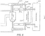
- Figure 6 shows an alternative two-stroke actuator assembly.
- Conventional assemblies such as shown in Fig. 1 move the two parts (e.g. a blocker door and thrust reverser sleeve) by virtue of them being respectively connected to the inner and outer pistons of the ball screw actuator.
- Such assemblies incorporate a synchronized follower device, SFD, 200 between the ball screw actuator 201 and the components to be moved (e.g. blocker door sleeve 220 and primary sleeve 210).
- the ball screw actuator 201 has one piston 202.
- the SFD comprises an outer housing 204 within which are axially moveably mounted an inner SFD piston 203 and an outer SFD piston 205.
- the free end 2031 of the inner SFD piston 203 is connected to the blocker door sleeve.
- the free end 2051 of the outer SFD piston 205 is connected to the primary sleeve and also to the ball screw actuator piston 202. In this embodiment, this is where the third fixation point 230, described above, is required and where the eccentric coupling would be mounted, as described above.
- the ball screw actuator piston 202 extends causing the outer SFD piston 205 to extend.
- the locking mechanism within the SFD causes the inner SFD piston 203 to also extend for part of the actuator piston 202 stroke, causing movement of the blocker door.
- the inner SFD piston 203 locks relative to the outer SFD piston 205 during the stroke such that for the rest of the stroke, only the outer SFD piston 205, and hence the primary sleeve 210, move.
- a dual stroke system requires an additional, third fixation point 30, 230 for the outer piston (of the actuator, in the simple embodiment, or of the SFD if provided).
- This third fixation point requires additional degrees of freedom to ensure that e.g. movement of the nacelle will not induce additional loads onto the actuator.
- angular movement of the fixation of the inner rod for deploying the second cowl should not be transferred to the fixation of the end of the outer rod with the first cowl and so the third fixation point needs to accommodate such angular movement.
- the solution provided by the present disclosure is to provide an eccentric coupling 7 at the third fixation point such as to permit movement, e.g. planar movement, of the outer rod 2 relative to its fixation to the first cowl when angular movement of the inner rod 3 is transmitted.
- a third coupling requires additional degrees of freedom to ensure, e.g. that nacelle structure movement will not induce side loads onto the actuator. This freedom of movement can be angular and planar.
- the third coupling must be designed to react to axial thrust loads generated from the actuator stroke and should not be restricted by friction.
- the coupling 7 can be best seen with reference to Figures 3A to 3C and Figure 5 .
- the coupling is mounted onto a fixed rod for demonstration purposes. In use, it would be mounted at the third fixation point 30, 230.
- the coupling comprises a housing 50, 60 which, here, is in the form of a ring mounted around the end of the outer rod 2 and which can be mounted to the component e.g. cowl being deployed by the outer rod by means of a coupling member such as a coupling bracket 9 which can, in turn, be mounted to the cowl either directly or, more preferably, via a steady bearing or a gimbal.
- 60 of the coupling 7 is an arrangement of bearings 100 that are housed eccentric to the axis between the bulk head attachment 4 and the rod end eye 5.
- the eccentric geometry allows uninhibited movement relative to the main axis, and the arrangement will accommodate positioned movement.
- the bearings 100 minimize the friction force during a planar displacement of the third fixation point.
- the eccentric coupling 7 and bearing arrangement 100 will now be described in more detail, and can best be seen in Figs. 3A , 4 and 5 .
- the coupling housing comprises an inner bearing mount 50 in the form of a ring that is mounted eccentrically to the main axis, with ball bearings 100' located between the inner bearing mount 50 and the outer rod 2.
- the coupling housing further comprises an outer bearing mount 60 which is mounted eccentrically around the inner bearing mount 50 via ball bearings 100".
- the coupling 7 is mounted with the gimbal via bearings 100"'.
- the off-set (eccentric) nature of the bearing mounts provides freedom for the main tube axis to displace in a planar motion relative to the gimbal centre. During this planar movement the eccentric bearing mounts 50, 60 will rotate. This is caused by the offset moment which allows the bearing mounts to cam away.
- the outer rod 2 determines the position of the cowl or other component to which it is attached.
- the inner rod 3 is driven to control the position of another component, cowl etc. Movement of the inner rod will, however, create forces acting on the outer rod.
- the coupling will, due to the bearing arrangement, permit eccentric movement to allow for these forces without transmitting them to the cowl driven by the outer rod.
- the coupling has a circular ring outer shape.
- Other shapes are, of course, possible and these will, at least to some extent be determined by the shape and form of the actuator components. It is also feasible that the coupling may have more than two eccentrically mounted bearing mounts.
- Such a coupling is advantageous for any actuators having three or more fixation points on a single axis.
Landscapes
- Engineering & Computer Science (AREA)
- General Engineering & Computer Science (AREA)
- Mechanical Engineering (AREA)
- Chemical & Material Sciences (AREA)
- Combustion & Propulsion (AREA)
- Transmission Devices (AREA)
Abstract
Description
- The present disclosure relates to a coupling, particularly an eccentric coupling, for example, for an actuator assembly, such as a thrust reverser actuation system (TRAS).
- Many mechanical systems require a coupling component or structure for coupling two or more parts of an assembly and to allow or prevent various degrees of movement between coupled parts.
- Coupling structures are known, for example, for joining components of an actuator assembly. Depending on the operation and structure of the actuator assembly, couplings or joints may be designed to accommodate some translation of movement between the two components joined by the coupling, so as to avoid 'force fighting' or damage to one or both components due to the force on one of the components.
- Some actuator assemblies (as discussed below) require three or more fixing points to accommodate relatively moveable parts of the actuator.
-
EP 3282132 teaches an eccentric coupling that allows some freedom of movement. This arrangement, however, may create undesirable friction. - The coupling of this disclosure will be specifically described in relation to an actuator such as commonly used in aircraft e.g. for deploying/moving cowls and flaps, more specifically, a TRAS. The coupling may, however, find a very wide range of applications and is not limited to this specific field. There is a general need for an eccentric coupling that permits some movement of a first component when a force is applied to a second component coupled to the first.
- In one aspect, there is provided a coupling assembly comprising a housing configured to be fixedly attached to a fixed component, an inner bearing mount arranged to be mounted eccentrically around a first moveable component via first bearings, an outer bearing mount mounted eccentrically around the inner bearing mount via second bearings, such that the inner and outer bearing mounts rotate eccentrically relative to the housing in response to a force exerted on the first moveable component.
- In another aspect, there is provided an assembly comprising a first moveable component and a second moveable component, moveable relative to the first, and a coupling as defined above.
- The assembly is preferably an actuator wherein the first and second moveable components are components arranged to actuate, respectively, first and second moveable parts.
- In one example, the first and second moveable components comprise telescopically arranged components such as a first and second (or outer and inner) rod.
- The actuator may be an actuator for use in a TRAS system or other aircraft system where the two moveable components actuate two different system parts such as cowls, flaps, doors or the like.
- The coupling housing is preferably in the form of a ring and the inner and outer bearing mounts are in the form of rings or annular disks mounted within the housing for eccentric movement within the housing.
- Preferred embodiments will now be described by way of example only and with reference to the drawings.
-
-
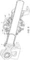
Figure 1 is a schematic view of an actuator, in use, requiring three fixation points. -
Figure 2 is a perspective view of an eccentric coupling in accordance with the disclosure (mounted onto a rod just to show the coupling). -
Figure 3A is a sectional view of the eccentric coupling such as shown inFig. 2 . -
Figures 3B and 3C are details of the housing components of the coupling fromFigure 3A showing the coupling in more detail. -
Figure 4 is an end view through the eccentric coupling. -
Figure 5 is a perspective view corresponding toFig. 3A . -
Figure 6 is a schematic view of an alternative actuator assembly, in use. - The coupling of the disclosure will now be described with reference to the drawings, by way of example only, in the specific context of an actuator. Many mechanical systems comprise moveable parts driven by actuators. As an example, in aircraft, actuators drive moveable parts such as doors, flaps or cowls. One example of the use of such actuators is in a TRAS where actuators are used to deploy flaps or cowls to decelerate an aircraft. When not in use, the actuators are used to withdraw or stow the flaps/cowls. Actuators may be hydraulic or pneumatic, or, increasingly, electric (or a combination of types).
- In traditional TRAS, flaps are driven by movement of a piston or rod of the actuator moving axially relative to a cylindrical housing. One end of the housing is attached to a fixed structure e.g. via a gimbal and the other end is open. The rod extends out of the open end of the cylinder and has an end e.g. an eye end that is attached to the movable cowl in a manner in which universal angular movement can be accommodated. To open the flap, the rod is driven axially out from the cylinder. To stow the cowl, the rod is retracted into the cylinder.
- Conventionally, a TRAS has an actuator to operate the thrust reverser doors and the blocker doors are operated from a linkage mechanism from the thrust reverser doors, or by some other separate mechanism. The use of separate actuators for each door or cowl adds to the weight, space requirements, risk of faults and maintenance requirements in an aircraft.
- Referring to
Fig. 1 , an actuator has been developed comprising a dual rod assembly wherein, within the cylindrical housing 1, are mounted two relatively moveable rods or pistons 2, 3, one inside the other. Such an assembly is able to deploy and/or stow two cowls e.g. the thrustreverser door 10 and theblocker door 20 using a single, relatively compact unit, as opposed to two separate mechanisms or actuators as in conventional systems. - In such a dual rod system, one end 1' of the housing 1 is attached to a fixed structure, e.g. via a bulk head attachment and the remote end 1" of the actuator is attached to a moveable part/cowl e.g. via an eye end (not shown). In between these two fixation points, though, is a
third fixation point 30 for the free end of the second rod/piston. An example can be seen in the figures. The cylindrical housing 1 accommodates an outer rod 2 and an inner rod 3, both rods axially moveable relative to the housing and to each other. The end of the outer rod extending from the open end of the cylinder is fixed to a first moveable part/cowl, flap, door etc., 10, e.g. via a gimbal or bearing (not shown). The end of the inner rod 3 is fixed to a second moveable cowl/flap/door 20 e.g. via theeye end 5 mentioned above. Actuation of the outer rod will cause deployment of thefirst cowl 10; actuation of the inner rod will cause deployment of thesecond cowl 20. -
Figure 6 shows an alternative two-stroke actuator assembly. Conventional assemblies such as shown inFig. 1 move the two parts (e.g. a blocker door and thrust reverser sleeve) by virtue of them being respectively connected to the inner and outer pistons of the ball screw actuator. - Recent improvements in actuator assemblies have been aimed at a reduced envelope for the actuator components and/or providing a variable driving force in each stage of actuation. Such assemblies incorporate a synchronized follower device, SFD, 200 between the
ball screw actuator 201 and the components to be moved (e.g.blocker door sleeve 220 and primary sleeve 210). In such assemblies, theball screw actuator 201 has onepiston 202. The SFD comprises anouter housing 204 within which are axially moveably mounted aninner SFD piston 203 and anouter SFD piston 205. Thefree end 2031 of the inner SFDpiston 203 is connected to the blocker door sleeve. The free end 2051 of the outer SFDpiston 205 is connected to the primary sleeve and also to the ballscrew actuator piston 202. In this embodiment, this is where thethird fixation point 230, described above, is required and where the eccentric coupling would be mounted, as described above. - On deployment, briefly, the ball
screw actuator piston 202 extends causing theouter SFD piston 205 to extend. The locking mechanism within the SFD (not described here, but as described in, e.g.EP 3228853 ) causes theinner SFD piston 203 to also extend for part of theactuator piston 202 stroke, causing movement of the blocker door. Theinner SFD piston 203 locks relative to theouter SFD piston 205 during the stroke such that for the rest of the stroke, only theouter SFD piston 205, and hence theprimary sleeve 210, move. - It can be seen that, compared to a conventional single stroke actuator with fixation points at the two ends, a dual stroke system requires an additional,
third fixation point - The solution provided by the present disclosure is to provide an
eccentric coupling 7 at the third fixation point such as to permit movement, e.g. planar movement, of the outer rod 2 relative to its fixation to the first cowl when angular movement of the inner rod 3 is transmitted. - A third coupling requires additional degrees of freedom to ensure, e.g. that nacelle structure movement will not induce side loads onto the actuator. This freedom of movement can be angular and planar. The third coupling must be designed to react to axial thrust loads generated from the actuator stroke and should not be restricted by friction.
- The
coupling 7 can be best seen with reference toFigures 3A to 3C andFigure 5 . In these figures, the coupling is mounted onto a fixed rod for demonstration purposes. In use, it would be mounted at thethird fixation point housing coupling bracket 9 which can, in turn, be mounted to the cowl either directly or, more preferably, via a steady bearing or a gimbal. Within thehousing coupling 7 is an arrangement ofbearings 100 that are housed eccentric to the axis between thebulk head attachment 4 and therod end eye 5. The eccentric geometry allows uninhibited movement relative to the main axis, and the arrangement will accommodate positioned movement. Thebearings 100 minimize the friction force during a planar displacement of the third fixation point. - The
eccentric coupling 7 andbearing arrangement 100 will now be described in more detail, and can best be seen inFigs. 3A ,4 and5 . The coupling housing comprises an inner bearing mount 50 in the form of a ring that is mounted eccentrically to the main axis, with ball bearings 100' located between theinner bearing mount 50 and the outer rod 2. The coupling housing further comprises an outer bearing mount 60 which is mounted eccentrically around the inner bearing mount 50 viaball bearings 100". Thecoupling 7 is mounted with the gimbal viabearings 100"'. - When a displacement of the gimbal is applied, the off-set (eccentric) nature of the bearing mounts provides freedom for the main tube axis to displace in a planar motion relative to the gimbal centre. During this planar movement the eccentric bearing mounts 50, 60 will rotate. This is caused by the offset moment which allows the bearing mounts to cam away.
- In use, therefore, the outer rod 2 determines the position of the cowl or other component to which it is attached. The inner rod 3 is driven to control the position of another component, cowl etc. Movement of the inner rod will, however, create forces acting on the outer rod. The coupling will, due to the bearing arrangement, permit eccentric movement to allow for these forces without transmitting them to the cowl driven by the outer rod.
- In the embodiment described and shown, the coupling has a circular ring outer shape. Other shapes are, of course, possible and these will, at least to some extent be determined by the shape and form of the actuator components. It is also feasible that the coupling may have more than two eccentrically mounted bearing mounts.
- Such a coupling is advantageous for any actuators having three or more fixation points on a single axis.
Claims (6)
- A coupling assembly comprising a housing configured to be fixedly attached to a fixed component, an inner bearing mount (50) arranged to be mounted eccentrically around a first moveable component (2) via first bearings (100'), an outer bearing mount (60) mounted eccentrically around the inner bearing mount via second bearings (100"), such that the inner and outer bearing mounts rotate eccentrically relative to the housing in response to a force exerted on the first moveable component.
- The coupling of claim 1, wherein the housing is in the form of a ring and the inner and outer bearing mounts are in the form of rings or annular discs mounted within the housing for eccentric movement within the housing.
- An assembly comprising a first moveable component (2) and a second moveable component (3), moveable relative to the first, and a coupling as claimed in claim 1 or 2.
- The assembly of claim 3, being an actuator wherein the first and second moveable components are components arranged to actuate, respectively, first (10) and second (20) moveable parts.
- The assembly of claim 4, wherein the first and second moveable components comprise telescopically arranged components such as a first and second (or outer and inner) rod.
- The assembly of claim 4 or 5 for use in an aircraft TRAS system.
Priority Applications (2)
| Application Number | Priority Date | Filing Date | Title |
|---|---|---|---|
| EP18275032.3A EP3534038B1 (en) | 2018-03-01 | 2018-03-01 | Actuator comprising a dual rod assembly and an eccentric coupling |
| US16/221,782 US11280294B2 (en) | 2018-03-01 | 2018-12-17 | Coupling with eccentric bearing arrangement |
Applications Claiming Priority (1)
| Application Number | Priority Date | Filing Date | Title |
|---|---|---|---|
| EP18275032.3A EP3534038B1 (en) | 2018-03-01 | 2018-03-01 | Actuator comprising a dual rod assembly and an eccentric coupling |
Publications (2)
| Publication Number | Publication Date |
|---|---|
| EP3534038A1 true EP3534038A1 (en) | 2019-09-04 |
| EP3534038B1 EP3534038B1 (en) | 2023-05-03 |
Family
ID=61569185
Family Applications (1)
| Application Number | Title | Priority Date | Filing Date |
|---|---|---|---|
| EP18275032.3A Active EP3534038B1 (en) | 2018-03-01 | 2018-03-01 | Actuator comprising a dual rod assembly and an eccentric coupling |
Country Status (2)
| Country | Link |
|---|---|
| US (1) | US11280294B2 (en) |
| EP (1) | EP3534038B1 (en) |
Families Citing this family (3)
| Publication number | Priority date | Publication date | Assignee | Title |
|---|---|---|---|---|
| EP3282132B1 (en) * | 2016-08-08 | 2019-10-02 | Goodrich Actuation Systems Limited | Actuator with a coupling |
| US10669013B2 (en) * | 2018-02-13 | 2020-06-02 | The Boeing Company | Split gimbal |
| US11066152B2 (en) * | 2018-05-25 | 2021-07-20 | The Boeing Company | Slotted entry gimbal |
Citations (4)
| Publication number | Priority date | Publication date | Assignee | Title |
|---|---|---|---|---|
| DE102005044956A1 (en) * | 2005-09-20 | 2007-03-22 | Voith Patent Gmbh | Spreader roll |
| DE102006040777A1 (en) * | 2006-08-31 | 2008-03-06 | Schaeffler Kg | rolling bearing unit |
| EP3228853A1 (en) | 2016-04-08 | 2017-10-11 | Goodrich Actuation Systems Limited | Thrust reverser actuator |
| EP3282132A1 (en) | 2016-08-08 | 2018-02-14 | Goodrich Actuation Systems Limited | Coupling |
Family Cites Families (5)
| Publication number | Priority date | Publication date | Assignee | Title |
|---|---|---|---|---|
| FR2754565B1 (en) | 1996-10-10 | 1999-01-08 | Hispano Suiza Sa | PUSH INVERTER WITH CONTROLLED LEAKAGE FLOW DOORS |
| DE102005044958A1 (en) * | 2005-09-20 | 2007-03-22 | Voith Patent Gmbh | Spreader roll |
| GB2449281A (en) * | 2007-05-17 | 2008-11-19 | Goodrich Actuation Systems Ltd | Screw and nut actuator |
| US8002217B2 (en) | 2007-11-16 | 2011-08-23 | Spirit Aerosystems, Inc. | System for adjustment of thrust reverser pivot door |
| GB0917057D0 (en) * | 2009-09-29 | 2009-11-11 | Goodrich Actuation Systems Ltd | Thrust reverser actuation |
-
2018
- 2018-03-01 EP EP18275032.3A patent/EP3534038B1/en active Active
- 2018-12-17 US US16/221,782 patent/US11280294B2/en active Active
Patent Citations (4)
| Publication number | Priority date | Publication date | Assignee | Title |
|---|---|---|---|---|
| DE102005044956A1 (en) * | 2005-09-20 | 2007-03-22 | Voith Patent Gmbh | Spreader roll |
| DE102006040777A1 (en) * | 2006-08-31 | 2008-03-06 | Schaeffler Kg | rolling bearing unit |
| EP3228853A1 (en) | 2016-04-08 | 2017-10-11 | Goodrich Actuation Systems Limited | Thrust reverser actuator |
| EP3282132A1 (en) | 2016-08-08 | 2018-02-14 | Goodrich Actuation Systems Limited | Coupling |
Also Published As
| Publication number | Publication date |
|---|---|
| EP3534038B1 (en) | 2023-05-03 |
| US20190271282A1 (en) | 2019-09-05 |
| US11280294B2 (en) | 2022-03-22 |
Similar Documents
| Publication | Publication Date | Title |
|---|---|---|
| EP2855261B1 (en) | Blow down actuator assembly | |
| US11280294B2 (en) | Coupling with eccentric bearing arrangement | |
| EP3552956B1 (en) | Method of operation of a linear actuator | |
| US5125131A (en) | Hinge locking mechanism with disengage action | |
| US8827205B2 (en) | Pneumatic blow-down actuator | |
| US8621978B2 (en) | Actuator for opening an aircraft engine nacelle cowl | |
| US11644089B2 (en) | Telescopic ballscrew actuator | |
| EP2604514A2 (en) | Automatically locking linear actuator | |
| US6389915B1 (en) | Dual load path ball screw with rod end swivel | |
| EP1922490B1 (en) | Exterior mechanical interlock for a linear actuator | |
| US5360185A (en) | Linear actuator, in particular for driving an aircraft landing gear leg | |
| EP1922248B1 (en) | Trim actuator actuating system for a hydraulically actuatable trimmable horizontal stabilizer actuator | |
| JP2013237435A (en) | Drive screw assembly and landing gear assembly with same | |
| EP2352670A1 (en) | Landing gear bay door with roller slot mechanism | |
| EP3301326B1 (en) | Linear actuator with multi-degree of freedom mounting structure | |
| EP3282132B1 (en) | Actuator with a coupling | |
| US6837054B2 (en) | Actuator assembly with synchronized hydraulic actuators | |
| JP2000272595A (en) | Annular aggregate pitch controller for helicopter rotor | |
| EP1288478A1 (en) | Synchronization cross-feed system | |
| US8356477B2 (en) | Dual linear actuator | |
| KR20210035817A (en) | Actuator | |
| EP3578463B1 (en) | Dual mode actuator | |
| EP3330570B1 (en) | Control system for an actuator | |
| EP3489547A1 (en) | Kinematic system with motion control device | |
| JP2020063822A (en) | Actuator |
Legal Events
| Date | Code | Title | Description |
|---|---|---|---|
| PUAI | Public reference made under article 153(3) epc to a published international application that has entered the european phase |
Free format text: ORIGINAL CODE: 0009012 |
|
| STAA | Information on the status of an ep patent application or granted ep patent |
Free format text: STATUS: THE APPLICATION HAS BEEN PUBLISHED |
|
| AK | Designated contracting states |
Kind code of ref document: A1 Designated state(s): AL AT BE BG CH CY CZ DE DK EE ES FI FR GB GR HR HU IE IS IT LI LT LU LV MC MK MT NL NO PL PT RO RS SE SI SK SM TR |
|
| AX | Request for extension of the european patent |
Extension state: BA ME |
|
| STAA | Information on the status of an ep patent application or granted ep patent |
Free format text: STATUS: REQUEST FOR EXAMINATION WAS MADE |
|
| 17P | Request for examination filed |
Effective date: 20200304 |
|
| RBV | Designated contracting states (corrected) |
Designated state(s): AL AT BE BG CH CY CZ DE DK EE ES FI FR GB GR HR HU IE IS IT LI LT LU LV MC MK MT NL NO PL PT RO RS SE SI SK SM TR |
|
| STAA | Information on the status of an ep patent application or granted ep patent |
Free format text: STATUS: EXAMINATION IS IN PROGRESS |
|
| 17Q | First examination report despatched |
Effective date: 20210927 |
|
| GRAP | Despatch of communication of intention to grant a patent |
Free format text: ORIGINAL CODE: EPIDOSNIGR1 |
|
| STAA | Information on the status of an ep patent application or granted ep patent |
Free format text: STATUS: GRANT OF PATENT IS INTENDED |
|
| RIC1 | Information provided on ipc code assigned before grant |
Ipc: F02K 1/76 20060101ALN20230131BHEP Ipc: F16H 25/24 20060101ALN20230131BHEP Ipc: F16C 23/10 20060101ALI20230131BHEP Ipc: F16C 29/00 20060101ALI20230131BHEP Ipc: F16H 25/20 20060101AFI20230131BHEP |
|
| GRAS | Grant fee paid |
Free format text: ORIGINAL CODE: EPIDOSNIGR3 |
|
| INTG | Intention to grant announced |
Effective date: 20230216 |
|
| GRAA | (expected) grant |
Free format text: ORIGINAL CODE: 0009210 |
|
| STAA | Information on the status of an ep patent application or granted ep patent |
Free format text: STATUS: THE PATENT HAS BEEN GRANTED |
|
| AK | Designated contracting states |
Kind code of ref document: B1 Designated state(s): AL AT BE BG CH CY CZ DE DK EE ES FI FR GB GR HR HU IE IS IT LI LT LU LV MC MK MT NL NO PL PT RO RS SE SI SK SM TR |
|
| REG | Reference to a national code |
Ref country code: GB Ref legal event code: FG4D |
|
| REG | Reference to a national code |
Ref country code: AT Ref legal event code: REF Ref document number: 1564848 Country of ref document: AT Kind code of ref document: T Effective date: 20230515 Ref country code: CH Ref legal event code: EP |
|
| REG | Reference to a national code |
Ref country code: DE Ref legal event code: R096 Ref document number: 602018049160 Country of ref document: DE |
|
| REG | Reference to a national code |
Ref country code: IE Ref legal event code: FG4D |
|
| P01 | Opt-out of the competence of the unified patent court (upc) registered |
Effective date: 20230706 |
|
| REG | Reference to a national code |
Ref country code: LT Ref legal event code: MG9D |
|
| REG | Reference to a national code |
Ref country code: NL Ref legal event code: MP Effective date: 20230503 |
|
| REG | Reference to a national code |
Ref country code: AT Ref legal event code: MK05 Ref document number: 1564848 Country of ref document: AT Kind code of ref document: T Effective date: 20230503 |
|
| PG25 | Lapsed in a contracting state [announced via postgrant information from national office to epo] |
Ref country code: SE Free format text: LAPSE BECAUSE OF FAILURE TO SUBMIT A TRANSLATION OF THE DESCRIPTION OR TO PAY THE FEE WITHIN THE PRESCRIBED TIME-LIMIT Effective date: 20230503 Ref country code: PT Free format text: LAPSE BECAUSE OF FAILURE TO SUBMIT A TRANSLATION OF THE DESCRIPTION OR TO PAY THE FEE WITHIN THE PRESCRIBED TIME-LIMIT Effective date: 20230904 Ref country code: NO Free format text: LAPSE BECAUSE OF FAILURE TO SUBMIT A TRANSLATION OF THE DESCRIPTION OR TO PAY THE FEE WITHIN THE PRESCRIBED TIME-LIMIT Effective date: 20230803 Ref country code: NL Free format text: LAPSE BECAUSE OF FAILURE TO SUBMIT A TRANSLATION OF THE DESCRIPTION OR TO PAY THE FEE WITHIN THE PRESCRIBED TIME-LIMIT Effective date: 20230503 Ref country code: ES Free format text: LAPSE BECAUSE OF FAILURE TO SUBMIT A TRANSLATION OF THE DESCRIPTION OR TO PAY THE FEE WITHIN THE PRESCRIBED TIME-LIMIT Effective date: 20230503 Ref country code: AT Free format text: LAPSE BECAUSE OF FAILURE TO SUBMIT A TRANSLATION OF THE DESCRIPTION OR TO PAY THE FEE WITHIN THE PRESCRIBED TIME-LIMIT Effective date: 20230503 |
|
| PG25 | Lapsed in a contracting state [announced via postgrant information from national office to epo] |
Ref country code: RS Free format text: LAPSE BECAUSE OF FAILURE TO SUBMIT A TRANSLATION OF THE DESCRIPTION OR TO PAY THE FEE WITHIN THE PRESCRIBED TIME-LIMIT Effective date: 20230503 Ref country code: PL Free format text: LAPSE BECAUSE OF FAILURE TO SUBMIT A TRANSLATION OF THE DESCRIPTION OR TO PAY THE FEE WITHIN THE PRESCRIBED TIME-LIMIT Effective date: 20230503 Ref country code: LV Free format text: LAPSE BECAUSE OF FAILURE TO SUBMIT A TRANSLATION OF THE DESCRIPTION OR TO PAY THE FEE WITHIN THE PRESCRIBED TIME-LIMIT Effective date: 20230503 Ref country code: LT Free format text: LAPSE BECAUSE OF FAILURE TO SUBMIT A TRANSLATION OF THE DESCRIPTION OR TO PAY THE FEE WITHIN THE PRESCRIBED TIME-LIMIT Effective date: 20230503 Ref country code: IS Free format text: LAPSE BECAUSE OF FAILURE TO SUBMIT A TRANSLATION OF THE DESCRIPTION OR TO PAY THE FEE WITHIN THE PRESCRIBED TIME-LIMIT Effective date: 20230903 Ref country code: HR Free format text: LAPSE BECAUSE OF FAILURE TO SUBMIT A TRANSLATION OF THE DESCRIPTION OR TO PAY THE FEE WITHIN THE PRESCRIBED TIME-LIMIT Effective date: 20230503 Ref country code: GR Free format text: LAPSE BECAUSE OF FAILURE TO SUBMIT A TRANSLATION OF THE DESCRIPTION OR TO PAY THE FEE WITHIN THE PRESCRIBED TIME-LIMIT Effective date: 20230804 |
|
| PG25 | Lapsed in a contracting state [announced via postgrant information from national office to epo] |
Ref country code: FI Free format text: LAPSE BECAUSE OF FAILURE TO SUBMIT A TRANSLATION OF THE DESCRIPTION OR TO PAY THE FEE WITHIN THE PRESCRIBED TIME-LIMIT Effective date: 20230503 |
|
| PG25 | Lapsed in a contracting state [announced via postgrant information from national office to epo] |
Ref country code: SK Free format text: LAPSE BECAUSE OF FAILURE TO SUBMIT A TRANSLATION OF THE DESCRIPTION OR TO PAY THE FEE WITHIN THE PRESCRIBED TIME-LIMIT Effective date: 20230503 |
|
| PG25 | Lapsed in a contracting state [announced via postgrant information from national office to epo] |
Ref country code: SM Free format text: LAPSE BECAUSE OF FAILURE TO SUBMIT A TRANSLATION OF THE DESCRIPTION OR TO PAY THE FEE WITHIN THE PRESCRIBED TIME-LIMIT Effective date: 20230503 Ref country code: SK Free format text: LAPSE BECAUSE OF FAILURE TO SUBMIT A TRANSLATION OF THE DESCRIPTION OR TO PAY THE FEE WITHIN THE PRESCRIBED TIME-LIMIT Effective date: 20230503 Ref country code: RO Free format text: LAPSE BECAUSE OF FAILURE TO SUBMIT A TRANSLATION OF THE DESCRIPTION OR TO PAY THE FEE WITHIN THE PRESCRIBED TIME-LIMIT Effective date: 20230503 Ref country code: EE Free format text: LAPSE BECAUSE OF FAILURE TO SUBMIT A TRANSLATION OF THE DESCRIPTION OR TO PAY THE FEE WITHIN THE PRESCRIBED TIME-LIMIT Effective date: 20230503 Ref country code: DK Free format text: LAPSE BECAUSE OF FAILURE TO SUBMIT A TRANSLATION OF THE DESCRIPTION OR TO PAY THE FEE WITHIN THE PRESCRIBED TIME-LIMIT Effective date: 20230503 Ref country code: CZ Free format text: LAPSE BECAUSE OF FAILURE TO SUBMIT A TRANSLATION OF THE DESCRIPTION OR TO PAY THE FEE WITHIN THE PRESCRIBED TIME-LIMIT Effective date: 20230503 |
|
| REG | Reference to a national code |
Ref country code: DE Ref legal event code: R097 Ref document number: 602018049160 Country of ref document: DE |
|
| PLBE | No opposition filed within time limit |
Free format text: ORIGINAL CODE: 0009261 |
|
| STAA | Information on the status of an ep patent application or granted ep patent |
Free format text: STATUS: NO OPPOSITION FILED WITHIN TIME LIMIT |
|
| 26N | No opposition filed |
Effective date: 20240206 |
|
| PG25 | Lapsed in a contracting state [announced via postgrant information from national office to epo] |
Ref country code: SI Free format text: LAPSE BECAUSE OF FAILURE TO SUBMIT A TRANSLATION OF THE DESCRIPTION OR TO PAY THE FEE WITHIN THE PRESCRIBED TIME-LIMIT Effective date: 20230503 |
|
| PG25 | Lapsed in a contracting state [announced via postgrant information from national office to epo] |
Ref country code: SI Free format text: LAPSE BECAUSE OF FAILURE TO SUBMIT A TRANSLATION OF THE DESCRIPTION OR TO PAY THE FEE WITHIN THE PRESCRIBED TIME-LIMIT Effective date: 20230503 |
|
| REG | Reference to a national code |
Ref country code: CH Ref legal event code: PL |
|
| PG25 | Lapsed in a contracting state [announced via postgrant information from national office to epo] |
Ref country code: BG Free format text: LAPSE BECAUSE OF FAILURE TO SUBMIT A TRANSLATION OF THE DESCRIPTION OR TO PAY THE FEE WITHIN THE PRESCRIBED TIME-LIMIT Effective date: 20230503 |
|
| PG25 | Lapsed in a contracting state [announced via postgrant information from national office to epo] |
Ref country code: LU Free format text: LAPSE BECAUSE OF NON-PAYMENT OF DUE FEES Effective date: 20240301 |
|
| PG25 | Lapsed in a contracting state [announced via postgrant information from national office to epo] |
Ref country code: MC Free format text: LAPSE BECAUSE OF FAILURE TO SUBMIT A TRANSLATION OF THE DESCRIPTION OR TO PAY THE FEE WITHIN THE PRESCRIBED TIME-LIMIT Effective date: 20230503 |
|
| PG25 | Lapsed in a contracting state [announced via postgrant information from national office to epo] |
Ref country code: MC Free format text: LAPSE BECAUSE OF FAILURE TO SUBMIT A TRANSLATION OF THE DESCRIPTION OR TO PAY THE FEE WITHIN THE PRESCRIBED TIME-LIMIT Effective date: 20230503 Ref country code: LU Free format text: LAPSE BECAUSE OF NON-PAYMENT OF DUE FEES Effective date: 20240301 Ref country code: BG Free format text: LAPSE BECAUSE OF FAILURE TO SUBMIT A TRANSLATION OF THE DESCRIPTION OR TO PAY THE FEE WITHIN THE PRESCRIBED TIME-LIMIT Effective date: 20230503 |
|
| REG | Reference to a national code |
Ref country code: BE Ref legal event code: MM Effective date: 20240331 |
|
| PG25 | Lapsed in a contracting state [announced via postgrant information from national office to epo] |
Ref country code: BE Free format text: LAPSE BECAUSE OF NON-PAYMENT OF DUE FEES Effective date: 20240331 |
|
| PG25 | Lapsed in a contracting state [announced via postgrant information from national office to epo] |
Ref country code: IE Free format text: LAPSE BECAUSE OF NON-PAYMENT OF DUE FEES Effective date: 20240301 |
|
| PG25 | Lapsed in a contracting state [announced via postgrant information from national office to epo] |
Ref country code: IE Free format text: LAPSE BECAUSE OF NON-PAYMENT OF DUE FEES Effective date: 20240301 Ref country code: BE Free format text: LAPSE BECAUSE OF NON-PAYMENT OF DUE FEES Effective date: 20240331 Ref country code: CH Free format text: LAPSE BECAUSE OF NON-PAYMENT OF DUE FEES Effective date: 20240331 |
|
| PGFP | Annual fee paid to national office [announced via postgrant information from national office to epo] |
Ref country code: IT Payment date: 20250218 Year of fee payment: 8 |
|
| PG25 | Lapsed in a contracting state [announced via postgrant information from national office to epo] |
Ref country code: CY Free format text: LAPSE BECAUSE OF FAILURE TO SUBMIT A TRANSLATION OF THE DESCRIPTION OR TO PAY THE FEE WITHIN THE PRESCRIBED TIME-LIMIT; INVALID AB INITIO Effective date: 20180301 |
|
| PG25 | Lapsed in a contracting state [announced via postgrant information from national office to epo] |
Ref country code: HU Free format text: LAPSE BECAUSE OF FAILURE TO SUBMIT A TRANSLATION OF THE DESCRIPTION OR TO PAY THE FEE WITHIN THE PRESCRIBED TIME-LIMIT; INVALID AB INITIO Effective date: 20180301 |
|
| PG25 | Lapsed in a contracting state [announced via postgrant information from national office to epo] |
Ref country code: TR Free format text: LAPSE BECAUSE OF FAILURE TO SUBMIT A TRANSLATION OF THE DESCRIPTION OR TO PAY THE FEE WITHIN THE PRESCRIBED TIME-LIMIT Effective date: 20230503 |
|
| PGFP | Annual fee paid to national office [announced via postgrant information from national office to epo] |
Ref country code: GB Payment date: 20260324 Year of fee payment: 9 |
|
| PGFP | Annual fee paid to national office [announced via postgrant information from national office to epo] |
Ref country code: DE Payment date: 20260320 Year of fee payment: 9 |
|
| PGFP | Annual fee paid to national office [announced via postgrant information from national office to epo] |
Ref country code: FR Payment date: 20260324 Year of fee payment: 9 |