EP3534021A1 - Half thrust bearing - Google Patents
Half thrust bearing Download PDFInfo
- Publication number
- EP3534021A1 EP3534021A1 EP19153952.7A EP19153952A EP3534021A1 EP 3534021 A1 EP3534021 A1 EP 3534021A1 EP 19153952 A EP19153952 A EP 19153952A EP 3534021 A1 EP3534021 A1 EP 3534021A1
- Authority
- EP
- European Patent Office
- Prior art keywords
- thrust bearing
- half thrust
- recess
- sliding surface
- grooves
- Prior art date
- Legal status (The legal status is an assumption and is not a legal conclusion. Google has not performed a legal analysis and makes no representation as to the accuracy of the status listed.)
- Granted
Links
- 238000002485 combustion reaction Methods 0.000 claims description 18
- 238000005461 lubrication Methods 0.000 description 22
- 239000001996 bearing alloy Substances 0.000 description 13
- 239000010410 layer Substances 0.000 description 13
- 239000002184 metal Substances 0.000 description 7
- 229910052751 metal Inorganic materials 0.000 description 7
- 239000011248 coating agent Substances 0.000 description 4
- 238000000576 coating method Methods 0.000 description 4
- 230000007423 decrease Effects 0.000 description 3
- 239000000126 substance Substances 0.000 description 3
- 238000007796 conventional method Methods 0.000 description 2
- 230000002093 peripheral effect Effects 0.000 description 2
- 239000012791 sliding layer Substances 0.000 description 2
- 238000004804 winding Methods 0.000 description 2
- 229910000640 Fe alloy Inorganic materials 0.000 description 1
- 229910000831 Steel Inorganic materials 0.000 description 1
- 239000000956 alloy Substances 0.000 description 1
- 229910045601 alloy Inorganic materials 0.000 description 1
- 230000005540 biological transmission Effects 0.000 description 1
- 229910052797 bismuth Inorganic materials 0.000 description 1
- 239000000446 fuel Substances 0.000 description 1
- 229910052745 lead Inorganic materials 0.000 description 1
- 238000000034 method Methods 0.000 description 1
- 239000011342 resin composition Substances 0.000 description 1
- 239000010959 steel Substances 0.000 description 1
- 229920003002 synthetic resin Polymers 0.000 description 1
- 239000000057 synthetic resin Substances 0.000 description 1
- 229910052718 tin Inorganic materials 0.000 description 1
Images


Classifications
-
- F—MECHANICAL ENGINEERING; LIGHTING; HEATING; WEAPONS; BLASTING
- F16—ENGINEERING ELEMENTS AND UNITS; GENERAL MEASURES FOR PRODUCING AND MAINTAINING EFFECTIVE FUNCTIONING OF MACHINES OR INSTALLATIONS; THERMAL INSULATION IN GENERAL
- F16C—SHAFTS; FLEXIBLE SHAFTS; ELEMENTS OR CRANKSHAFT MECHANISMS; ROTARY BODIES OTHER THAN GEARING ELEMENTS; BEARINGS
- F16C9/00—Bearings for crankshafts or connecting-rods; Attachment of connecting-rods
- F16C9/02—Crankshaft bearings
-
- F—MECHANICAL ENGINEERING; LIGHTING; HEATING; WEAPONS; BLASTING
- F02—COMBUSTION ENGINES; HOT-GAS OR COMBUSTION-PRODUCT ENGINE PLANTS
- F02F—CYLINDERS, PISTONS OR CASINGS, FOR COMBUSTION ENGINES; ARRANGEMENTS OF SEALINGS IN COMBUSTION ENGINES
- F02F7/00—Casings, e.g. crankcases or frames
- F02F7/0043—Arrangements of mechanical drive elements
- F02F7/0053—Crankshaft bearings fitted in the crankcase
-
- F—MECHANICAL ENGINEERING; LIGHTING; HEATING; WEAPONS; BLASTING
- F16—ENGINEERING ELEMENTS AND UNITS; GENERAL MEASURES FOR PRODUCING AND MAINTAINING EFFECTIVE FUNCTIONING OF MACHINES OR INSTALLATIONS; THERMAL INSULATION IN GENERAL
- F16C—SHAFTS; FLEXIBLE SHAFTS; ELEMENTS OR CRANKSHAFT MECHANISMS; ROTARY BODIES OTHER THAN GEARING ELEMENTS; BEARINGS
- F16C17/00—Sliding-contact bearings for exclusively rotary movement
- F16C17/04—Sliding-contact bearings for exclusively rotary movement for axial load only
- F16C17/045—Sliding-contact bearings for exclusively rotary movement for axial load only with grooves in the bearing surface to generate hydrodynamic pressure, e.g. spiral groove thrust bearings
-
- F—MECHANICAL ENGINEERING; LIGHTING; HEATING; WEAPONS; BLASTING
- F16—ENGINEERING ELEMENTS AND UNITS; GENERAL MEASURES FOR PRODUCING AND MAINTAINING EFFECTIVE FUNCTIONING OF MACHINES OR INSTALLATIONS; THERMAL INSULATION IN GENERAL
- F16C—SHAFTS; FLEXIBLE SHAFTS; ELEMENTS OR CRANKSHAFT MECHANISMS; ROTARY BODIES OTHER THAN GEARING ELEMENTS; BEARINGS
- F16C17/00—Sliding-contact bearings for exclusively rotary movement
- F16C17/10—Sliding-contact bearings for exclusively rotary movement for both radial and axial load
- F16C17/102—Sliding-contact bearings for exclusively rotary movement for both radial and axial load with grooves in the bearing surface to generate hydrodynamic pressure
-
- F—MECHANICAL ENGINEERING; LIGHTING; HEATING; WEAPONS; BLASTING
- F16—ENGINEERING ELEMENTS AND UNITS; GENERAL MEASURES FOR PRODUCING AND MAINTAINING EFFECTIVE FUNCTIONING OF MACHINES OR INSTALLATIONS; THERMAL INSULATION IN GENERAL
- F16C—SHAFTS; FLEXIBLE SHAFTS; ELEMENTS OR CRANKSHAFT MECHANISMS; ROTARY BODIES OTHER THAN GEARING ELEMENTS; BEARINGS
- F16C33/00—Parts of bearings; Special methods for making bearings or parts thereof
- F16C33/02—Parts of sliding-contact bearings
- F16C33/04—Brasses; Bushes; Linings
- F16C33/046—Brasses; Bushes; Linings divided or split, e.g. half-bearings or rolled sleeves
-
- F—MECHANICAL ENGINEERING; LIGHTING; HEATING; WEAPONS; BLASTING
- F16—ENGINEERING ELEMENTS AND UNITS; GENERAL MEASURES FOR PRODUCING AND MAINTAINING EFFECTIVE FUNCTIONING OF MACHINES OR INSTALLATIONS; THERMAL INSULATION IN GENERAL
- F16C—SHAFTS; FLEXIBLE SHAFTS; ELEMENTS OR CRANKSHAFT MECHANISMS; ROTARY BODIES OTHER THAN GEARING ELEMENTS; BEARINGS
- F16C33/00—Parts of bearings; Special methods for making bearings or parts thereof
- F16C33/02—Parts of sliding-contact bearings
- F16C33/04—Brasses; Bushes; Linings
- F16C33/06—Sliding surface mainly made of metal
- F16C33/10—Construction relative to lubrication
- F16C33/1005—Construction relative to lubrication with gas, e.g. air, as lubricant
- F16C33/101—Details of the bearing surface, e.g. means to generate pressure such as lobes or wedges
-
- F—MECHANICAL ENGINEERING; LIGHTING; HEATING; WEAPONS; BLASTING
- F16—ENGINEERING ELEMENTS AND UNITS; GENERAL MEASURES FOR PRODUCING AND MAINTAINING EFFECTIVE FUNCTIONING OF MACHINES OR INSTALLATIONS; THERMAL INSULATION IN GENERAL
- F16C—SHAFTS; FLEXIBLE SHAFTS; ELEMENTS OR CRANKSHAFT MECHANISMS; ROTARY BODIES OTHER THAN GEARING ELEMENTS; BEARINGS
- F16C33/00—Parts of bearings; Special methods for making bearings or parts thereof
- F16C33/02—Parts of sliding-contact bearings
- F16C33/04—Brasses; Bushes; Linings
- F16C33/06—Sliding surface mainly made of metal
- F16C33/10—Construction relative to lubrication
- F16C33/1025—Construction relative to lubrication with liquid, e.g. oil, as lubricant
- F16C33/106—Details of distribution or circulation inside the bearings, e.g. details of the bearing surfaces to affect flow or pressure of the liquid
- F16C33/1065—Grooves on a bearing surface for distributing or collecting the liquid
-
- F—MECHANICAL ENGINEERING; LIGHTING; HEATING; WEAPONS; BLASTING
- F16—ENGINEERING ELEMENTS AND UNITS; GENERAL MEASURES FOR PRODUCING AND MAINTAINING EFFECTIVE FUNCTIONING OF MACHINES OR INSTALLATIONS; THERMAL INSULATION IN GENERAL
- F16C—SHAFTS; FLEXIBLE SHAFTS; ELEMENTS OR CRANKSHAFT MECHANISMS; ROTARY BODIES OTHER THAN GEARING ELEMENTS; BEARINGS
- F16C33/00—Parts of bearings; Special methods for making bearings or parts thereof
- F16C33/02—Parts of sliding-contact bearings
- F16C33/04—Brasses; Bushes; Linings
- F16C33/06—Sliding surface mainly made of metal
- F16C33/10—Construction relative to lubrication
- F16C33/1025—Construction relative to lubrication with liquid, e.g. oil, as lubricant
- F16C33/106—Details of distribution or circulation inside the bearings, e.g. details of the bearing surfaces to affect flow or pressure of the liquid
- F16C33/107—Grooves for generating pressure
-
- F—MECHANICAL ENGINEERING; LIGHTING; HEATING; WEAPONS; BLASTING
- F16—ENGINEERING ELEMENTS AND UNITS; GENERAL MEASURES FOR PRODUCING AND MAINTAINING EFFECTIVE FUNCTIONING OF MACHINES OR INSTALLATIONS; THERMAL INSULATION IN GENERAL
- F16C—SHAFTS; FLEXIBLE SHAFTS; ELEMENTS OR CRANKSHAFT MECHANISMS; ROTARY BODIES OTHER THAN GEARING ELEMENTS; BEARINGS
- F16C33/00—Parts of bearings; Special methods for making bearings or parts thereof
- F16C33/30—Parts of ball or roller bearings
- F16C33/46—Cages for rollers or needles
- F16C33/56—Selection of substances
-
- F—MECHANICAL ENGINEERING; LIGHTING; HEATING; WEAPONS; BLASTING
- F16—ENGINEERING ELEMENTS AND UNITS; GENERAL MEASURES FOR PRODUCING AND MAINTAINING EFFECTIVE FUNCTIONING OF MACHINES OR INSTALLATIONS; THERMAL INSULATION IN GENERAL
- F16C—SHAFTS; FLEXIBLE SHAFTS; ELEMENTS OR CRANKSHAFT MECHANISMS; ROTARY BODIES OTHER THAN GEARING ELEMENTS; BEARINGS
- F16C2240/00—Specified values or numerical ranges of parameters; Relations between them
- F16C2240/40—Linear dimensions, e.g. length, radius, thickness, gap
- F16C2240/42—Groove sizes
-
- H—ELECTRICITY
- H02—GENERATION; CONVERSION OR DISTRIBUTION OF ELECTRIC POWER
- H02K—DYNAMO-ELECTRIC MACHINES
- H02K7/00—Arrangements for handling mechanical energy structurally associated with dynamo-electric machines, e.g. structural association with mechanical driving motors or auxiliary dynamo-electric machines
- H02K7/08—Structural association with bearings
- H02K7/09—Structural association with bearings with magnetic bearings
Definitions
- the present invention relates to a semi-annular-shaped half thrust bearing having a sliding surface for receiving an axial force of a crankshaft of an internal combustion engine.
- a crankshaft of an internal combustion engine is rotatably supported in its journal part by a lower portion of a cylinder block of the engine via a main bearing constituted by a pair of half bearings combined into a cylindrical shape.
- a main bearing constituted by a pair of half bearings combined into a cylindrical shape.
- One or both of the pair of half bearings are combined with a half thrust bearing for receiving an axial force of the crankshaft.
- the half thrust bearing is placed on one or both end faces in an axial direction of the half bearing.
- the half thrust bearing receives an axial force generated in an axial direction of the crankshaft. That is, the half thrust bearing is provided for the purpose of bearing an axial force applied to the crankshaft, for example, when the crankshaft is connected to a transmission by a clutch.
- the crankshaft of the internal combustion engine is supported in its journal part by the lower portion of the cylinder block of the engine via the main bearing constituted by the pair of half bearings.
- Lubrication oil is fed from an oil gallery in a cylinder block wall, via a through hole in a wall of the main bearing, into a lubrication oil groove formed along an inner surface of the main bearing.
- the lubrication oil is supplied into the lubrication oil groove of the main bearing and is then supplied to the half thrust bearing.
- an oil pump for supplying lubrication oil has been downsized in order to improve fuel economy of the internal combustion engine, and this causes a reduction in an amount of lubrication oil supplied to the bearings. Accordingly, an amount of lubrication oil leaked from end faces of the main bearing decreases, and thus an amount of lubrication oil supplied to the half thrust bearing also tends to decrease.
- JP 2001-323928A and JP 2000-504089A each disclose a configuration for improving retainability of lubrication oil on the sliding surface by forming oil grooves along a circumferential direction on the sliding surface ( JP 2001-323928A ) and by forming a plurality of minute recesses on the sliding surface ( JP 2000-504089A ).
- An object of the present invention is to provide a half thrust bearing of a crankshaft of an internal combustion engine, that can suppress seizure during operation of the internal combustion engine.
- a half thrust bearing for receiving an axial force of a crankshaft of an internal combustion engine.
- the half thrust bearing has a semi-annular shape, and has a sliding surface for receiving the axial force and a back surface opposite to the sliding surface.
- the sliding surface includes a plurality of recesses.
- Each recess has a recess surface recessed from the sliding surface toward the back surface of the half thrust bearing.
- the recess surface is convex toward the back surface in a cross-sectional view in a direction along a center line of the half thrust bearing.
- the recess surface includes a plurality of grooves along a center line.
- the grooves are recessed from the recess surface toward the back surface of the half thrust bearing.
- the grooves extend along the center line direction V of the half thrust bearing so that smooth surfaces and the grooves are alternately arranged on the recess surface in a horizontal direction H of the half thrust bearing.
- the “horizontal direction (H)” of the half thrust bearing indicates a direction connecting center points of both end faces of the half thrust bearing.
- the “center line direction (V)” (or vertical direction) of the half thrust bearing indicates a direction parallel to the sliding surface and perpendicular to the horizontal direction (H).
- the recesses preferably have a depth of 2 to 50 ⁇ m.
- the grooves preferably have a depth of 0.2 to 3 ⁇ m. Furthermore, the grooves preferably have a width of 5 to 50 ⁇ m. Furthermore, the grooves are preferably arranged with a pitch of 5 to 100 ⁇ m.
- the recesses preferably have an opening of a circular shape, an elliptical shape, or a quadrilateral shape. More preferably, the opening has an elliptical shape with a major axis of the elliptical shape extending along the center line direction of the half thrust bearing.
- the recess surface is preferably convex toward the back surface of the half thrust bearing in a cross-sectional view along the horizontal direction of the half thrust bearing.
- the recesses are preferably uniformly located throughout the sliding surface of the half thrust bearing.
- a bearing housing 4 is constituted by a cylinder block 2 and a bearing cap 3 attached to a lower portion of the cylinder block 2.
- the bearing housing 4 has a bearing hole 5 and seats 6.
- the bearing hole 5 is circular and passes through side surfaces of the bearing housing 4.
- the seats 6 each are configured as an annular recess at a peripheral edge of the bearing hole 5 on the side surface.
- half bearings 7 combined into a cylindrical shape are fitted.
- the half bearings 7 rotatably support a journal part 11 of a crankshaft.
- the half thrust bearings 8 combined into an annular shape are fitted.
- the half thrust bearings 8 receive an axial force f (see Fig. 8 ) via a thrust collar 12 of the crankshaft.
- the half bearing 7 closest to the cylinder block 2 (on an upper side) among the half bearings 7 constituting a main bearing has an inner surface having a lubrication oil groove 71 and a through hole 72 passing through the half bearing 7 from the lubrication oil groove 71 to an outer surface of the half bearing 7.
- the lubrication oil groove may be formed in both the upper and lower half bearings.
- the half bearings 7 each include, at both ends, crush reliefs each adjacent to a surface at which the half bearings 7 are butted against each other.
- lubrication oil is pressurized and discharged by an oil pump (not shown), and the lubrication oil is supplied from an inner oil passage of the cylinder block 2, via the through hole 72 passing through a wall of the half bearing 7, into the lubrication oil groove 71 on the inner surface of the half bearing 7.
- Part of the lubrication oil supplied into the lubrication oil groove 71 is supplied to the inner surface of the half bearing 7.
- Another part of the lubrication oil enters an opening of an inner oil passage of the crankshaft (not shown) on a surface of the journal part and flows toward a crankpin.
- Another part of the lubrication oil flows outward from the both ends in a width direction of each of the pair of half bearings 7 constituting the main bearing through a gap between surfaces of the crush reliefs of the half bearings 7 and the surface of the journal part 11 of the crankshaft.
- the lubrication oil flowing outward from the both ends in the width direction of each of the half bearings 7 mainly flows into a gap between a sliding surface 81 of the half thrust bearing 8 and a surface of the thrust collar 12 of the crankshaft (hereinafter, the gap between the sliding surface 81 and the surface of the thrust collar 12 is referred to as "sliding surface 81/thrust collar 12 gap").
- the thrust bearing 8 bears an axial force f from the crankshaft, by pressure generated in oil between the sliding surface of the thrust bearing 8 and the thrust collar surface of the crankshaft.
- the surface of the thrust collar 12 of the crankshaft repeats movement to be closer to the sliding surface 81 of the half thrust bearing 8 and movement to be away from the sliding surface 81 of the half thrust bearing 8 while changing an inclination angle with respect to the sliding surface 81 or winding.
- the surface of the thrust collar 12 comes closest to an outer edge or an inner edge in a radial direction of the sliding surface of the half thrust bearing, in particular, near a circumferential center portion of the half thrust bearing (in a range of a circumferential angle of -30° to +30° from a circumferential center toward circumferential ends of the half thrust bearing).
- the surface of the thrust collar 12 is more likely to directly come into contact with a portion near the outer edge or the inner edge in the radial direction of the sliding surface 81 near the circumferential center portion of the half thrust bearing 8. Thus, damage such as seizure is more likely to occur.
- a conventional half thrust bearing ( JP 2001-323928A ) having a sliding surface including a plurality of circumferential thin grooves extending along an entire circumferential length of the sliding surface has the following problems. While a surface of a thrust collar 12 separated from a portion of the sliding surface near a circumferential center portion of the half thrust bearing is moving relatively closer to the sliding surface, oil between the sliding surface of the half thrust bearing and the surface of the thrust collar flows in the circumferential grooves, and flows out from open ends of the oil groove or the circumferential grooves in a thrust relief into the oil groove or a thrust relief gap. Thus, even when the surface of the thrust collar comes closest to the sliding surface, pressure of the oil does not become sufficiently high.
- the surface of the thrust collar 12 is more likely to directly come into contact with a portion near an outer edge or an inner edge in a radial direction of the sliding surface near the circumferential center portion of the half thrust bearing. Thus, damage (seizure) is more likely to occur.
- a conventional half thrust bearing JP 2000-504089A having a sliding surface including a plurality of minute recesses has the following problems.
- a surface of a thrust collar separated from the sliding surface of the half thrust bearing having the minute recesses moves relatively closer to the sliding surface and the surface of the thrust collar comes closest to the sliding surface, oil in the recess is compressed to have high pressure, and flows out from the recess to a gap (sliding surface/thrust collar gap) between the sliding surface and the surface of the thrust collar.
- a gap sliding surface/thrust collar gap
- the amount of oil is small near the outer edge or the inner edge in the radial direction of the sliding surface near a circumferential center portion of the half thrust bearing. Accordingly, the surface of the thrust collar is more likely to directly come into contact with a portion near the outer edge or the inner edge in the radial direction of the sliding surface near the circumferential center portion of the half thrust bearing. Thus, damage (seizure) is more likely to occur.
- the present invention addresses such problems of the conventional techniques.
- An example of a configuration of a half thrust bearing according to the present invention will be described below.
- Figs. 2 to 7 show a first embodiment of the half thrust bearing 8 according to the present invention.
- the half thrust bearing 8 has a flat semi-annular shape and is made of bimetal produced by applying a thin bearing alloy layer to a back-metal layer made of steel.
- the half thrust bearing 8 has the sliding surface 81 for supporting the thrust collar 12.
- the sliding surface 81 is a surface of the bearing alloy layer.
- the sliding surface 81 is parallel to a back surface which is opposite to a surface of the back-metal layer bonded to the bearing alloy layer.
- the half thrust bearing 8 may include thrust reliefs 81b on the surface of the bearing alloy layer in regions adjacent to respective circumferential end faces 83.
- the surface of the bearing alloy layer may have two oil grooves 81a between the thrust reliefs 81b on both sides.
- the "sliding surface 81" indicates the surface of the bearing alloy layer excluding the thrust reliefs 81b and the oil grooves 81a.
- the thrust reliefs 81b have a thickness gradually reduced toward the respective end faces.
- the thrust reliefs 81b each extend along an entire width of the circumferential end face in the radial direction of the half thrust bearing 8.
- the thrust reliefs 81b are provided in order to reduce positional deviation between the circumferential end faces 83 of the pair of half thrust bearings 8 caused by, for example, positional deviation that occurs when the half thrust bearings 8 are assembled in the split-type bearing housing 4.
- Fig. 2 shows an example of a plurality of recesses 84 on the sliding surface 81 of the half thrust bearing 8.
- Fig. 3 shows an example of the recess 84 viewed from a sliding surface side.
- the present invention is not limited to the embodiment. For facilitating understanding, the recesses are exaggerated in the drawings.
- the recesses 84 on the sliding surface 81 of the half thrust bearing 8 have openings having the same shape, area, and size, such as a depth, and are uniformly arranged substantially throughout the sliding surface.
- the "uniform arrangement" of the recesses 84 on the sliding surface 81 does not indicate strictly geometrically uniform arrangement, but may be approximately or substantially uniform arrangement.
- the terms “horizontal direction H” and "center line direction V" of the half thrust bearing 8 will be described below.
- the horizontal direction H is a direction connecting both center points of the circumferential end faces 83 of the half thrust bearing 8.
- the center line direction (vertical direction) V of the half thrust bearing is a direction parallel to the sliding surface and perpendicular to the horizontal direction H.
- the center line direction V may also be defined as a direction perpendicular to the imaginary plane 90
- the horizontal direction H may also be defined as a direction parallel to the plane 90 and parallel to the sliding surface 81.
- the half thrust bearing 8 does not need to have the complete semi-annular shape and may have, for example, an inclined end face as shown in Fig. 16 .
- the horizontal direction H and the center line direction V are defined as the above.
- the “center line” is an imaginary line in the sliding surface that passes through a center point of the semi-annular shape of the half thrust bearing 8 and is perpendicular to the horizontal direction H (or the imaginary plane 90).
- a portion of the half thrust bearing 8 through which the center line passes is referred to as "circumferential center C" of the half thrust bearing.
- Fig. 3 shows the recess 84 having a circular opening.
- the recess 84A has a smooth surface 84S and a plurality of grooves 84G.
- the grooves 84G extend in a direction parallel to the center line direction V of the half thrust bearing 8.
- the smooth surfaces 84S and the grooves 84G are alternately arranged in the horizontal direction H in the recess.
- the term "smooth surface 84S" indicates a smooth surface having no grooves, protrusions, or the like, but may have minute (sufficiently small as compared with the rooves) asperities.
- the recess surface is recessed toward the back surface of the half thrust bearing 8 in a cross-sectional view (an A-A cross section in Fig. 3 ) cut along the center line direction V. That is, the recess surface forms a convex curve toward the back surface.
- the "recess surface” indicates a smooth surface of the recess excluding the grooves.
- the groove in cross-sectional view in the center line direction of the half thrust bearing 8 is also recessed from the recess surface toward the back surface of the half thrust bearing 8.
- the recess 84 preferably forms a convex curve toward the back surface also in a cross-sectional view cut along the horizontal direction H of the half thrust bearing. Furthermore, the recess 84 preferably forms a convex curve toward the back surface also in a cross-sectional view in any direction of the half thrust bearing 8.
- the "cross section” indicates a cross section perpendicular to the sliding surface 81.
- the recess 84 preferably has a depth D1 of 2 to 50 ⁇ m, and more preferably of 2 to 25 ⁇ m.
- the depth of the recess 84 is defined as a distance between an imaginary plane extending along the sliding surface over the opening of the recess and a deepest part of the smooth surface of the recess.
- the opening of the recess 84 has a circular shape
- the opening may have a diameter of 0.05 to 5 mm.
- the opening of the recess has a shape other than the circular shape, the opening preferably has the diameter of a circle having an area equal to that of the opening (equivalent circle diameter).
- the grooves 84G extend from a peripheral edge of the recess 84 and along the center line direction V, when viewed from the sliding surface side of the half thrust bearing.
- the grooves 84G are allowed to be slightly tilted (up to 3°) with respect to the center line direction V.
- the grooves 84G preferably have a depth D2 of 0.2 to 3 ⁇ m.
- the depth D2 is smaller than the depth D1 of the recess 84.
- the "depth of the groove” indicates a depth at a deepest part of the groove from the smooth surface adjacent to the groove viewed in cross-sectional view along a width direction of the groove.
- a width W of the grooves 84G (i.e., a width is a length along the horizontal direction H of the groove 84G on the surface 84S of the recess 84, see Fig. 6 ) is preferably 5 to 50 ⁇ m.
- the width W is preferably determined such that at least five grooves 84G can be formed in a single recess 84.
- the grooves are arranged with a pitch P (i.e., a length between the deepest parts of the adjacent grooves 84G in the horizontal direction H, see Fig. 6 ) in the horizontal direction H.
- the pitch is preferably 5 to 100 ⁇ m.
- a depth D2 of the groove 84G which is a depth from the surface 84S of the recess 84, is made constant over its length or along a direction in which the groove 84G extends, except in circumferential end regions of the recess.
- the width W of the groove 84G is preferably also made constant over the length (see Fig. 5 ).
- a cross section of the groove 84G is preferably V-shaped. However, the shape of the cross section of the groove 84G is not limited to the V-shape and may have another shape.
- the depth D2 and the width W of the groove 84G may be changed along the length of the groove 84G.
- the "depth of the groove” and the “width of the groove” respectively indicate the maximum depth and the maximum width of the groove 84G, and the maximum values are preferably sized to meet the above described depth and width.
- the half thrust bearing 8 of the embodiment may have a sliding layer made of a Cu bearing alloy or an Al bearing alloy on a back-metal layer made of an Fe alloy.
- the half thrust bearing may be constituted only by a Cu bearing alloy or an Al bearing alloy without a back-metal layer.
- the sliding surface 81 including an inner surface of the recess 84 may have a surface coating or overlay made of one of Bi, Sn and Pb or an alloy thereof, which are softer than the bearing alloy.
- the surface coating may be made of a resin composition including synthetic resin as a main component. (Even in the case, the surface of the sliding layer is referred to as "a sliding surface" in this context).
- the surface of the recess 84 preferably does not have such a surface coating.
- the surface 84S of the recess 84 or a surface of the groove 84G has such a soft surface coating, when oil contains many foreign substances, the foreign substances are more likely to be embedded and accumulated. If the foreign substances are embedded and accumulated on the surface 84S of the recess 84 or the surface of the groove 84G, turbulence is more likely to occur in the oil flowing in the recess.
- the half thrust bearing 8 of the present invention has the recesses 84 on the sliding surface, and each recess 84 has the smooth surface 84S and the plurality of grooves 84G.
- the half thrust bearing is less likely to cause damage (seizure). A reason thereof will be described below.
- the surface of the thrust collar 12 of the crankshaft repeats movement to be closer to the sliding surface 81 of the half thrust bearing 8 and movement to be away from the sliding surface 81 of the half thrust bearing 8 while changing an inclination angle with respect to the sliding surface 81 or winding.
- the surface of the thrust collar 12 comes closest to the outer edge or the inner edge in the radial direction of the sliding surface of the half thrust bearing, in particular, near the circumferential center portion of the half thrust bearing.
- Fig. 9 shows a state where the surface of the thrust collar 12 of the crankshaft separated from the sliding surface 81 of the half thrust bearing 8 has moved relatively closer to the sliding surface 81, and the surface of the thrust collar 12 has come closest to the sliding surface 81.
- the oil in the recess 84 is compressed to have high pressure and flows out from the recess 84 into the sliding surface 81/thrust collar 12 gap.
- the surface of the recess 84 has the grooves 84G extending in a direction parallel to the center line direction V of the half thrust bearing 8.
- the oil in the recess 84 is guided to the grooves 84G (F1) and flows in the same direction as the center line direction V of the half thrust bearing 8.
- the oil then flows out into the sliding surface 81/thrust collar gap 12 toward the outer edge and the inner edge in the radial direction of the half thrust bearing 8.
- an oil flow following the rotating surface of the thrust collar 12 has been formed.
- the oil compressed to have high pressure in the recess 84 mainly becomes the oil flow F1 flowing in the center line direction V of the half thrust bearing 8 in the sliding surface 81/thrust collar 12 gap, and thus the oil flow F1 is strong.
- the oil flow F1 flowing in the center line direction V of the half thrust bearing 8 becomes stronger than the oil flow following the rotating surface of the thrust collar 12, and thus the oil is supplied to the outer edge and the inner edge in the radial direction of the sliding surface of the half thrust bearing 8.
- the recesses 84 having the grooves 84G extending in a direction parallel to the center line direction V of the half thrust bearing 8 are located in a region around the circumferential center portion of the half thrust bearing 8 (i.e. in the range of -30° to +30° from the circumferential center C toward the circumferential ends of the half thrust bearing), as well as a region other than the region near the circumferential center portion .
- This is due to the following reason. That is, as the recess 84 is located closer to the circumferential end face 83, the longitudinal direction of the groove 84G forms a smaller angle with the circumferential direction of the half thrust bearing. Accordingly, the oil flow F1 out from the recess 84 flows in the circumferential direction of the half thrust bearing 8. Thus, following the rotating surface of the thrust collar 12, more oil is more likely to flow toward the circumferential center portion side of the half thrust bearing 8.
- a plurality of recesses 84 are substantially uniformly located throughout the sliding surface, and each recess 84 has an elliptical opening with its major axis L1 extending parallel to the center line direction V of the half thrust bearing 8 and its minor axis L2 extending in the horizontal direction H of the half thrust bearing 8.
- the major axis L of the elliptical opening of the recess 84 may be slightly tilted (up to 3°) with respect to the center line direction V of the half thrust bearing 8.
- the recess 84 may have a curved surface recessed toward the back surface (convex toward the back surface) of the half thrust bearing 8, not only in a cross-sectional view in the center line direction of the half thrust bearing 8 but also in a cross-sectional view in any direction other than the center line direction.
- the maximum depth D1 from the sliding surface 81 may be the same in the recesses 84.
- each recesses 84 has an elliptical opening with its major axis L1 extending parallel to the center line direction V of the half thrust bearing 8. Accordingly, when the surface of the thrust collar 12 comes closest to a portion of the sliding surface 81 near the circumferential center portion of the half thrust bearing 8, oil in the recess 84 is guided to the groove 84G and the oil is more likely to flow toward the outer edge and the inner edge in the radial direction of the half thrust bearing 8. Thus, the oil is more likely to flow into the sliding surface/thrust collar gap of the half thrust bearing 8 toward the outer edge and the inner edge in the radial direction of the half thrust bearing 8.
- the sliding surface 81 has two oil grooves 81a, and recesses 84 are substantially uniformly located only in a region between the two oil grooves 81a on the sliding surface 81. No recess 84 is located in regions between the oil grooves 81a and respective circumferential end faces 83 (or thrust reliefs 81b). Other configurations are the same as those of the half thrust bearing described in the first embodiment.
- the recesses 84 may be formed only in a region of the sliding surface 81 near the circumferential center portion of the half thrust bearing 8 (i.e. a region in the range of -30° to +30° from the circumferential center C toward the circumferential ends of the half thrust bearing) where the surface of the thrust collar 12 is more likely to come into contact with the sliding surface 81.
- the recesses 84 may be formed only in a region of the sliding surface 81 near the circumferential end face 83 of the half thrust bearing 8.
- FIG. 13 shows a recess 84 having a quadrilateral opening.
- An arrow V indicates the center line direction V of the half thrust bearing 8.
- Two sides of the quadrilateral opening of the recess extend in the center line direction V of the half thrust bearing 8.
- Grooves 84G are omitted in Fig. 13 .
- Fig. 14 shows a C-C cross section (i.e. a cross section in the horizontal direction H or across section cut along the horizontal direction H of the half thrust bearing 8) of the recess 84 in Fig. 13 .
- the cross section has a reverse trapezoidal shape, and a surface of the recess 84 is parallel to the sliding surface 81, excluding the surface at both ends of the recess 84 in the radial direction.
- the grooves 84G are omitted also in Fig. 14 .
- the surface of the recess 84 in a cross-sectional view in the center line direction V of the half thrust bearing 8 is curved and recessed toward the back surface of the half thrust bearing 8.
- Fig. 15 shows a recess 84 having a quadrilateral opening. Unlike in Fig. 13 , a diagonal line of the quadrilateral opening of the recess extends in the center line direction V of the half thrust bearing 8.
- a surface of the recess 84 in a cross-sectional view parallel to the center line direction V of the half thrust bearing 8 is curved and recessed toward the back surface of the half thrust bearing 8.
- the surface of the recess 84 in a cross-sectional view parallel to the horizontal direction H of the half thrust bearing 8 is curved and recessed toward the back surface.
- grooves 84G are omitted.
- circular, elliptical, and quadrilateral shapes are explained as the shape of the opening of the recess 84.
- these shapes of the opening do not indicate geometrically precise circular, elliptical, and quadrilateral shapes and they may be substantially circular, elliptical, and quadrilateral.
- the shape of the opening of the recess 84 is not limited to these shapes and other shapes may be applied.
- the half thrust bearing of the present invention has been described with the embodiments. The above description is made to the embodiments where the half thrust bearing of the present invention is applied to a thrust bearing constituted by combining a pair of the half thrust bearings into an annular shape for receiving an axial force of a crankshaft of an internal combustion engine.
- the half thrust bearing of the present invention is also applicable to a single thrust bearing for receiving an axial force of a crankshaft of an internal combustion engine.
- the half thrust bearing of the present invention may be made of bimetal composed of a back-metal layer and a bearing alloy or may be made of only a bearing alloy with no back-metal layer (also in this case, a surface to come into contact with the thrust collar is referred to as a sliding surface, and a surface opposite to the sliding surface is referred to as a back surface).
- the shape of the half thrust bearing of the present invention is not limited to a semi-annular shape having a length forming a circumferential angle of 180° in the circumferential direction, and may be a substantially semi-annular shape having a length forming a circumferential angle of slightly smaller than 180° in the circumferential direction.
- the half thrust bearing of the present invention may have an oil groove and a thrust relief having different shapes other than the shapes shown in the drawings.
- the half thrust bearing of the present invention may have no oil grooves or thrust reliefs.
- the sliding surface is parallel to the back surface of the back-metal layer, and the sliding surface has a constant thickness.
- the sliding surface may have a changing thickness, and for example, the thickness may be maximum at the inner edge of the sliding surface in the radial direction of the half thrust bearing and continuously decrease toward the outer edge of the sliding surface in the radial direction.
- the sliding surface may have a changing thickness in the circumferential direction of the half thrust bearing.
- only the sliding surface 81 includes the recesses 84.
- the present invention is not limited thereto, and a surface of the thrust relief 81b or a surface of the oil groove 81a may also include a recess/ recesses.
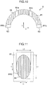
- circumferential end faces of the respective half thrust bearings 8 may be configured as inclined end faces 83A butted against each other as shown in Fig. 16 , at one or both of two butted portions of a pair of half thrust bearings 8.
- the inclined end faces 83A are each inclined at a predetermined angle ⁇ 1 with respect to a plane passing through the other circumferential end face which is not inclined.
- the circumferential end faces of the respective half thrust bearings 8 may have other shapes, such as a recessed shape and a corresponding protruding shape.
Landscapes
- Engineering & Computer Science (AREA)
- General Engineering & Computer Science (AREA)
- Mechanical Engineering (AREA)
- Chemical & Material Sciences (AREA)
- Oil, Petroleum & Natural Gas (AREA)
- Physics & Mathematics (AREA)
- Fluid Mechanics (AREA)
- Combustion & Propulsion (AREA)
- Sliding-Contact Bearings (AREA)
Abstract


Description
- The present invention relates to a semi-annular-shaped half thrust bearing having a sliding surface for receiving an axial force of a crankshaft of an internal combustion engine.
- A crankshaft of an internal combustion engine is rotatably supported in its journal part by a lower portion of a cylinder block of the engine via a main bearing constituted by a pair of half bearings combined into a cylindrical shape. One or both of the pair of half bearings are combined with a half thrust bearing for receiving an axial force of the crankshaft. The half thrust bearing is placed on one or both end faces in an axial direction of the half bearing.
- The half thrust bearing receives an axial force generated in an axial direction of the crankshaft. That is, the half thrust bearing is provided for the purpose of bearing an axial force applied to the crankshaft, for example, when the crankshaft is connected to a transmission by a clutch.
- The crankshaft of the internal combustion engine is supported in its journal part by the lower portion of the cylinder block of the engine via the main bearing constituted by the pair of half bearings. Lubrication oil is fed from an oil gallery in a cylinder block wall, via a through hole in a wall of the main bearing, into a lubrication oil groove formed along an inner surface of the main bearing. Thus, the lubrication oil is supplied into the lubrication oil groove of the main bearing and is then supplied to the half thrust bearing.
- In recent years, an oil pump for supplying lubrication oil has been downsized in order to improve fuel economy of the internal combustion engine, and this causes a reduction in an amount of lubrication oil supplied to the bearings. Accordingly, an amount of lubrication oil leaked from end faces of the main bearing decreases, and thus an amount of lubrication oil supplied to the half thrust bearing also tends to decrease. As a measure to address this problem, for example, it has been proposed to improve retainability of lubrication oil by forming thin grooves in parallel to each other on a sliding surface of the half thrust bearing (see
JP 2001- 323928A JP 2000-504089A - In recent years, due to the reduction in the amount of lubrication oil supplied to the half thrust bearing as described above, a surface of a thrust collar of the crankshaft directly comes into contact with a sliding surface of the half thrust bearing during operation of the internal combustion engine, and thus friction loss is more likely to occur. Furthermore, in recent years, a shaft diameter of the crankshaft is reduced in order to reduce a weight of the internal combustion engine, and this causes the crankshaft to have lower rigidity than a conventional crankshaft. Thus, during operation of the internal combustion engine, deflection is more likely to occur in the crankshaft, and this tends to cause the crankshaft to vibrate greatly. Accordingly, the surface of the thrust collar is more likely to directly come into contact with a portion of the sliding surface near a circumferential center portion of the half thrust bearing. Thus, damage such as seizure is more likely to occur.
- In order to address the situation,
JP 2001-323928A JP 2000-504089A JP 2001-323928A JP 2000-504089A - However, even if the technique of
JP 2001-323928A JP 2000-504089A - An object of the present invention is to provide a half thrust bearing of a crankshaft of an internal combustion engine, that can suppress seizure during operation of the internal combustion engine.
- In an aspect of the present invention, a half thrust bearing is provided for receiving an axial force of a crankshaft of an internal combustion engine. The half thrust bearing has a semi-annular shape, and has a sliding surface for receiving the axial force and a back surface opposite to the sliding surface. The sliding surface includes a plurality of recesses. Each recess has a recess surface recessed from the sliding surface toward the back surface of the half thrust bearing. The recess surface is convex toward the back surface in a cross-sectional view in a direction along a center line of the half thrust bearing. The recess surface includes a plurality of grooves along a center line. The grooves are recessed from the recess surface toward the back surface of the half thrust bearing. The grooves extend along the center line direction V of the half thrust bearing so that smooth surfaces and the grooves are alternately arranged on the recess surface in a horizontal direction H of the half thrust bearing.
- Here, the "horizontal direction (H)" of the half thrust bearing indicates a direction connecting center points of both end faces of the half thrust bearing. The "center line direction (V)" (or vertical direction) of the half thrust bearing indicates a direction parallel to the sliding surface and perpendicular to the horizontal direction (H).
- According to an embodiment of the present invention, the recesses preferably have a depth of 2 to 50 µm.
- According to an embodiment of the present invention, the grooves preferably have a depth of 0.2 to 3 µm. Furthermore, the grooves preferably have a width of 5 to 50 µm. Furthermore, the grooves are preferably arranged with a pitch of 5 to 100 µm.
- According to an embodiment of the present invention, the recesses preferably have an opening of a circular shape, an elliptical shape, or a quadrilateral shape. More preferably, the opening has an elliptical shape with a major axis of the elliptical shape extending along the center line direction of the half thrust bearing.
- According to an embodiment of the present invention, the recess surface is preferably convex toward the back surface of the half thrust bearing in a cross-sectional view along the horizontal direction of the half thrust bearing.
- According to an embodiment of the present invention, the recesses are preferably uniformly located throughout the sliding surface of the half thrust bearing.
-
-
Fig. 1 is an exploded perspective view of a bearing device. -
Fig. 2 is a front view of a half thrust bearing according to a first embodiment of the present invention. -
Fig. 3 shows a recess inFig. 2 , viewed from a sliding surface side. -
Fig. 4 is a cross-sectional view of an A-A cross section (along a center line direction) inFig. 3 . -
Fig. 5 is a cross-sectional view of a B-B cross section (along a horizontal direction) inFig. 3 . -
Fig. 6 is a cross-sectional view of grooves along the center line direction. -
Fig. 7 is a front view of half bearings and a thrust bearing. -
Fig. 8 is a cross-sectional view of the bearing device. -
Fig. 9 shows oil flows in the recess inFig. 3 . -
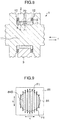
Fig. 10 is a front view of the half thrust bearing according to a second mbodiment of the present invention. -
Fig. 11 shows a recess inFig. 10 , viewed from the sliding surface side. -
Fig. 12 is a front view of the half thrust bearing according to a third embodiment of the present invention. -
Fig. 13 shows a recess of the half thrust bearing according to a fourth embodiment of the present invention, viewed from the sliding surface side. -
Fig. 14 is a cross-sectional view of a C-C cross section (i. e. a cross section along horizontal direction) inFig. 13 . -
Fig. 15 shows a recess of the half thrust bearing according to a fifth embodiment of the present invention, viewed from the sliding surface side. -
Fig. 16 shows butted portions of a pair of half thrust bearings according to another embodiment of the present invention, viewed from the sliding surface side. -
Fig. 17 shows a recess according to a conventional technique, viewed from the sliding surface side. - Embodiments of the present invention and their advantages will be described in detail below with reference to the accompanying drawings. The embodiments below are described merely as examples, and the present invention is not limited to the embodiments.
- First, with reference to
Figs. 1 ,7 and8 , a description will be given of a general configuration of a bearing device 1 including a half thrust bearing 8 of the present invention. As shown inFigs. 1 ,7 and8 , a bearing housing 4 is constituted by acylinder block 2 and abearing cap 3 attached to a lower portion of thecylinder block 2. The bearing housing 4 has abearing hole 5 andseats 6. Thebearing hole 5 is circular and passes through side surfaces of the bearing housing 4. Theseats 6 each are configured as an annular recess at a peripheral edge of thebearing hole 5 on the side surface. In thebearing hole 5, half bearings 7 combined into a cylindrical shape are fitted. The half bearings 7 rotatably support ajournal part 11 of a crankshaft. In theseats 6, thehalf thrust bearings 8 combined into an annular shape are fitted. Thehalf thrust bearings 8 receive an axial force f (seeFig. 8 ) via athrust collar 12 of the crankshaft. - As shown in
Fig. 7 , the half bearing 7 closest to the cylinder block 2 (on an upper side) among the half bearings 7 constituting a main bearing has an inner surface having alubrication oil groove 71 and a throughhole 72 passing through the half bearing 7 from thelubrication oil groove 71 to an outer surface of the half bearing 7. The lubrication oil groove may be formed in both the upper and lower half bearings. The half bearings 7 each include, at both ends, crush reliefs each adjacent to a surface at which the half bearings 7 are butted against each other. - In the bearing device 1, lubrication oil is pressurized and discharged by an oil pump (not shown), and the lubrication oil is supplied from an inner oil passage of the
cylinder block 2, via the throughhole 72 passing through a wall of the half bearing 7, into thelubrication oil groove 71 on the inner surface of the half bearing 7. Part of the lubrication oil supplied into thelubrication oil groove 71 is supplied to the inner surface of the half bearing 7. Another part of the lubrication oil enters an opening of an inner oil passage of the crankshaft (not shown) on a surface of the journal part and flows toward a crankpin. Another part of the lubrication oil flows outward from the both ends in a width direction of each of the pair of half bearings 7 constituting the main bearing through a gap between surfaces of the crush reliefs of the half bearings 7 and the surface of thejournal part 11 of the crankshaft. The lubrication oil flowing outward from the both ends in the width direction of each of the half bearings 7 mainly flows into a gap between a slidingsurface 81 of thehalf thrust bearing 8 and a surface of thethrust collar 12 of the crankshaft (hereinafter, the gap between the slidingsurface 81 and the surface of thethrust collar 12 is referred to as "slidingsurface 81/thrust collar 12 gap"). - In general, the
thrust bearing 8 bears an axial force f from the crankshaft, by pressure generated in oil between the sliding surface of thethrust bearing 8 and the thrust collar surface of the crankshaft. - During operation of the internal combustion engine, when deflection of the crankshaft causes the crankshaft to vibrate greatly, the surface of the
thrust collar 12 of the crankshaft repeats movement to be closer to the slidingsurface 81 of thehalf thrust bearing 8 and movement to be away from the slidingsurface 81 of thehalf thrust bearing 8 while changing an inclination angle with respect to the slidingsurface 81 or winding. The surface of thethrust collar 12 comes closest to an outer edge or an inner edge in a radial direction of the sliding surface of the half thrust bearing, in particular, near a circumferential center portion of the half thrust bearing (in a range of a circumferential angle of -30° to +30° from a circumferential center toward circumferential ends of the half thrust bearing). While the surface of thethrust collar 12 of the crankshaft is moving closer to a portion of the slidingsurface 81 near the circumferential center portion of thehalf thrust bearing 8, oil in a gap between the surface of thethrust collar 12 of the crankshaft and the slidingsurface 81 near the circumferential center portion of thehalf thrust bearing 8 is compressed to have an increased pressure. The oil having the pressure increased during the movement flows, following the surface of thethrust collar 12, in a circumferential direction of thehalf thrust bearing 8, and is thus less likely to flow toward the outer edge or the inner edge in the radial direction of the slidingsurface 81 of thehalf thrust bearing 8. Accordingly, the surface of thethrust collar 12 is more likely to directly come into contact with a portion near the outer edge or the inner edge in the radial direction of the slidingsurface 81 near the circumferential center portion of thehalf thrust bearing 8. Thus, damage such as seizure is more likely to occur. - A conventional half thrust bearing (
JP 2001-323928A thrust collar 12 separated from a portion of the sliding surface near a circumferential center portion of the half thrust bearing is moving relatively closer to the sliding surface, oil between the sliding surface of the half thrust bearing and the surface of the thrust collar flows in the circumferential grooves, and flows out from open ends of the oil groove or the circumferential grooves in a thrust relief into the oil groove or a thrust relief gap. Thus, even when the surface of the thrust collar comes closest to the sliding surface, pressure of the oil does not become sufficiently high. Accordingly, the surface of thethrust collar 12 is more likely to directly come into contact with a portion near an outer edge or an inner edge in a radial direction of the sliding surface near the circumferential center portion of the half thrust bearing. Thus, damage (seizure) is more likely to occur. - Furthermore, a conventional half thrust bearing (
JP 2000-504089A Fig. 17 , in a case where aminute recess 184 has a smooth surface, oil compressed to have high pressure in the recess and overflowing from the recess into the sliding surface/thrust collar gap flows in all directions (F2). Accordingly, the pressure is dispersed to the oil flows flowing in the respective directions. Including an oil flow toward an outer edge or an inner edge in a radial direction of the sliding surface of the half thrust bearing, the oil flows flowing out toward the respective directions from the recess into the gap has a low pressure. Immediately after flowing out from the recess into the gap, therefore, the oil flows change their direction to a circumferential direction of the half thrust bearing, following the rotating surface of the thrust collar. Thus, the amount of oil is small near the outer edge or the inner edge in the radial direction of the sliding surface near a circumferential center portion of the half thrust bearing. Accordingly, the surface of the thrust collar is more likely to directly come into contact with a portion near the outer edge or the inner edge in the radial direction of the sliding surface near the circumferential center portion of the half thrust bearing. Thus, damage (seizure) is more likely to occur. - The present invention addresses such problems of the conventional techniques. An example of a configuration of a half thrust bearing according to the present invention will be described below.
-
Figs. 2 to 7 show a first embodiment of thehalf thrust bearing 8 according to the present invention. Thehalf thrust bearing 8 has a flat semi-annular shape and is made of bimetal produced by applying a thin bearing alloy layer to a back-metal layer made of steel. Thehalf thrust bearing 8 has the slidingsurface 81 for supporting thethrust collar 12. The slidingsurface 81 is a surface of the bearing alloy layer. The slidingsurface 81 is parallel to a back surface which is opposite to a surface of the back-metal layer bonded to the bearing alloy layer. Thehalf thrust bearing 8 may include thrustreliefs 81b on the surface of the bearing alloy layer in regions adjacent to respective circumferential end faces 83. Furthermore, in order to enhance oil supply to the slidingsurface 8, the surface of the bearing alloy layer may have twooil grooves 81a between thethrust reliefs 81b on both sides. In this context, the "slidingsurface 81" indicates the surface of the bearing alloy layer excluding thethrust reliefs 81b and theoil grooves 81a. - The thrust reliefs 81b have a thickness gradually reduced toward the respective end faces. The thrust reliefs 81b each extend along an entire width of the circumferential end face in the radial direction of the
half thrust bearing 8. The thrust reliefs 81b are provided in order to reduce positional deviation between the circumferential end faces 83 of the pair ofhalf thrust bearings 8 caused by, for example, positional deviation that occurs when thehalf thrust bearings 8 are assembled in the split-type bearing housing 4. -
Fig. 2 shows an example of a plurality ofrecesses 84 on the slidingsurface 81 of thehalf thrust bearing 8.Fig. 3 shows an example of therecess 84 viewed from a sliding surface side. The present invention is not limited to the embodiment. For facilitating understanding, the recesses are exaggerated in the drawings. - In this embodiment, the
recesses 84 on the slidingsurface 81 of thehalf thrust bearing 8 have openings having the same shape, area, and size, such as a depth, and are uniformly arranged substantially throughout the sliding surface. The "uniform arrangement" of therecesses 84 on the slidingsurface 81 does not indicate strictly geometrically uniform arrangement, but may be approximately or substantially uniform arrangement. - The terms "horizontal direction H" and "center line direction V" of the
half thrust bearing 8 will be described below. The horizontal direction H is a direction connecting both center points of the circumferential end faces 83 of thehalf thrust bearing 8. The center line direction (vertical direction) V of the half thrust bearing is a direction parallel to the sliding surface and perpendicular to the horizontal direction H. When thehalf thrust bearing 8 has a complete semi-annular shape as shown inFig. 2 , the circumferential end faces 83 extend in a sameimaginary plane 90. Accordingly, the center line direction V may also be defined as a direction perpendicular to theimaginary plane 90, and the horizontal direction H may also be defined as a direction parallel to theplane 90 and parallel to the slidingsurface 81. However, thehalf thrust bearing 8 does not need to have the complete semi-annular shape and may have, for example, an inclined end face as shown inFig. 16 . Thus, the horizontal direction H and the center line direction V are defined as the above. - The "center line" is an imaginary line in the sliding surface that passes through a center point of the semi-annular shape of the
half thrust bearing 8 and is perpendicular to the horizontal direction H (or the imaginary plane 90). A portion of thehalf thrust bearing 8 through which the center line passes is referred to as "circumferential center C" of the half thrust bearing. -
Fig. 3 shows therecess 84 having a circular opening. The recess 84A has asmooth surface 84S and a plurality ofgrooves 84G. Thegrooves 84G extend in a direction parallel to the center line direction V of thehalf thrust bearing 8. Thus, thesmooth surfaces 84S and thegrooves 84G are alternately arranged in the horizontal direction H in the recess. The term "smooth surface 84S" indicates a smooth surface having no grooves, protrusions, or the like, but may have minute (sufficiently small as compared with the rooves) asperities. - In
Fig. 4 , the recess surface is recessed toward the back surface of thehalf thrust bearing 8 in a cross-sectional view (an A-A cross section inFig. 3 ) cut along the center line direction V. That is, the recess surface forms a convex curve toward the back surface. The "recess surface" indicates a smooth surface of the recess excluding the grooves. The groove in cross-sectional view in the center line direction of thehalf thrust bearing 8 is also recessed from the recess surface toward the back surface of thehalf thrust bearing 8. - In an embodiment, the
recess 84 preferably forms a convex curve toward the back surface also in a cross-sectional view cut along the horizontal direction H of the half thrust bearing. Furthermore, therecess 84 preferably forms a convex curve toward the back surface also in a cross-sectional view in any direction of thehalf thrust bearing 8. In this context, the "cross section" indicates a cross section perpendicular to the slidingsurface 81. - The
recess 84 preferably has a depth D1 of 2 to 50 µm, and more preferably of 2 to 25 µm. The depth of therecess 84 is defined as a distance between an imaginary plane extending along the sliding surface over the opening of the recess and a deepest part of the smooth surface of the recess. In a case where the opening of therecess 84 has a circular shape, the opening may have a diameter of 0.05 to 5 mm. In a case where the opening of the recess has a shape other than the circular shape, the opening preferably has the diameter of a circle having an area equal to that of the opening (equivalent circle diameter). - The
grooves 84G extend from a peripheral edge of therecess 84 and along the center line direction V, when viewed from the sliding surface side of the half thrust bearing. Thegrooves 84G are allowed to be slightly tilted (up to 3°) with respect to the center line direction V. - The
grooves 84G preferably have a depth D2 of 0.2 to 3 µm. The depth D2 is smaller than the depth D1 of therecess 84. The "depth of the groove" indicates a depth at a deepest part of the groove from the smooth surface adjacent to the groove viewed in cross-sectional view along a width direction of the groove. - A width W of the
grooves 84G (i.e., a width is a length along the horizontal direction H of thegroove 84G on thesurface 84S of therecess 84, seeFig. 6 ) is preferably 5 to 50 µm. The width W is preferably determined such that at least fivegrooves 84G can be formed in asingle recess 84. In therecess 84, the grooves are arranged with a pitch P (i.e., a length between the deepest parts of theadjacent grooves 84G in the horizontal direction H, seeFig. 6 ) in the horizontal direction H. The pitch is preferably 5 to 100 µm. - Preferably, a depth D2 of the
groove 84G, which is a depth from thesurface 84S of therecess 84, is made constant over its length or along a direction in which thegroove 84G extends, except in circumferential end regions of the recess. Furthermore, the width W of thegroove 84G is preferably also made constant over the length (seeFig. 5 ). A cross section of thegroove 84G is preferably V-shaped. However, the shape of the cross section of thegroove 84G is not limited to the V-shape and may have another shape. - The depth D2 and the width W of the
groove 84G may be changed along the length of thegroove 84G. In such a case, the "depth of the groove" and the "width of the groove" respectively indicate the maximum depth and the maximum width of thegroove 84G, and the maximum values are preferably sized to meet the above described depth and width. - The half thrust bearing 8 of the embodiment may have a sliding layer made of a Cu bearing alloy or an Al bearing alloy on a back-metal layer made of an Fe alloy. However, the half thrust bearing may be constituted only by a Cu bearing alloy or an Al bearing alloy without a back-metal layer. The sliding
surface 81 including an inner surface of therecess 84 may have a surface coating or overlay made of one of Bi, Sn and Pb or an alloy thereof, which are softer than the bearing alloy. Alternatively, the surface coating may be made of a resin composition including synthetic resin as a main component. (Even in the case, the surface of the sliding layer is referred to as "a sliding surface" in this context).
However, the surface of therecess 84 preferably does not have such a surface coating. If thesurface 84S of therecess 84 or a surface of thegroove 84G has such a soft surface coating, when oil contains many foreign substances, the foreign substances are more likely to be embedded and accumulated. If the foreign substances are embedded and accumulated on thesurface 84S of therecess 84 or the surface of thegroove 84G, turbulence is more likely to occur in the oil flowing in the recess. - As described above, the half thrust bearing 8 of the present invention has the
recesses 84 on the sliding surface, and eachrecess 84 has thesmooth surface 84S and the plurality ofgrooves 84G. Thus, the half thrust bearing is less likely to cause damage (seizure). A reason thereof will be described below. - As described above, during operation of the internal combustion engine, when deflection of the crankshaft causes the crankshaft to vibrate greatly, the surface of the
thrust collar 12 of the crankshaft repeats movement to be closer to the slidingsurface 81 of thehalf thrust bearing 8 and movement to be away from the slidingsurface 81 of thehalf thrust bearing 8 while changing an inclination angle with respect to the slidingsurface 81 or winding. The surface of thethrust collar 12 comes closest to the outer edge or the inner edge in the radial direction of the sliding surface of the half thrust bearing, in particular, near the circumferential center portion of the half thrust bearing. -
Fig. 9 shows a state where the surface of thethrust collar 12 of the crankshaft separated from the slidingsurface 81 of thehalf thrust bearing 8 has moved relatively closer to the slidingsurface 81, and the surface of thethrust collar 12 has come closest to the slidingsurface 81. In this state, the oil in therecess 84 is compressed to have high pressure and flows out from therecess 84 into the slidingsurface 81/thrust collar 12 gap. The surface of therecess 84 has thegrooves 84G extending in a direction parallel to the center line direction V of thehalf thrust bearing 8. Thus, the oil in therecess 84 is guided to thegrooves 84G (F1) and flows in the same direction as the center line direction V of thehalf thrust bearing 8. The oil then flows out into the slidingsurface 81/thrust collar gap 12 toward the outer edge and the inner edge in the radial direction of thehalf thrust bearing 8. - In the sliding
surface 81/thrust collar 12 gap, an oil flow following the rotating surface of thethrust collar 12 has been formed. As described above, the oil compressed to have high pressure in therecess 84 mainly becomes the oil flow F1 flowing in the center line direction V of thehalf thrust bearing 8 in the slidingsurface 81/thrust collar 12 gap, and thus the oil flow F1 is strong. Also near the circumferential center portion of thehalf thrust bearing 8, the oil flow F1 flowing in the center line direction V of thehalf thrust bearing 8 becomes stronger than the oil flow following the rotating surface of thethrust collar 12, and thus the oil is supplied to the outer edge and the inner edge in the radial direction of the sliding surface of thehalf thrust bearing 8. - Due to this oil flow, even when the surface of the
thrust collar 12 comes closest to the outer edge or the inner edge in the radial direction of the slidingsurface 81 of thehalf thrust bearing 8 near the circumferential center portion of the half thrust bearing, the surface of thethrust collar 12 is less likely to directly come into contact with the outer edge or the inner edge of the slidingsurface 81. - In the embodiment, the
recesses 84 having thegrooves 84G extending in a direction parallel to the center line direction V of thehalf thrust bearing 8 are located in a region around the circumferential center portion of the half thrust bearing 8 (i.e. in the range of -30° to +30° from the circumferential center C toward the circumferential ends of the half thrust bearing), as well as a region other than the region near the circumferential center portion . This is due to the following reason. That is, as therecess 84 is located closer to thecircumferential end face 83, the longitudinal direction of thegroove 84G forms a smaller angle with the circumferential direction of the half thrust bearing. Accordingly, the oil flow F1 out from therecess 84 flows in the circumferential direction of thehalf thrust bearing 8. Thus, following the rotating surface of thethrust collar 12, more oil is more likely to flow toward the circumferential center portion side of thehalf thrust bearing 8. - Alternative non-limiting embodiments of the present invention will be described below.
- In an embodiment shown in
Figs. 10 and 11 , a plurality ofrecesses 84 are substantially uniformly located throughout the sliding surface, and eachrecess 84 has an elliptical opening with its major axis L1 extending parallel to the center line direction V of thehalf thrust bearing 8 and its minor axis L2 extending in the horizontal direction H of thehalf thrust bearing 8. The major axis L of the elliptical opening of therecess 84 may be slightly tilted (up to 3°) with respect to the center line direction V of thehalf thrust bearing 8. - The
recess 84 may have a curved surface recessed toward the back surface (convex toward the back surface) of thehalf thrust bearing 8, not only in a cross-sectional view in the center line direction of thehalf thrust bearing 8 but also in a cross-sectional view in any direction other than the center line direction. The maximum depth D1 from the slidingsurface 81 may be the same in therecesses 84. - In the half thrust bearing 8 of the embodiment, each recesses 84 has an elliptical opening with its major axis L1 extending parallel to the center line direction V of the
half thrust bearing 8. Accordingly, when the surface of thethrust collar 12 comes closest to a portion of the slidingsurface 81 near the circumferential center portion of thehalf thrust bearing 8, oil in therecess 84 is guided to thegroove 84G and the oil is more likely to flow toward the outer edge and the inner edge in the radial direction of thehalf thrust bearing 8. Thus, the oil is more likely to flow into the sliding surface/thrust collar gap of thehalf thrust bearing 8 toward the outer edge and the inner edge in the radial direction of thehalf thrust bearing 8. - In an embodiment shown in
Fig. 12 , the slidingsurface 81 has twooil grooves 81a, and recesses 84 are substantially uniformly located only in a region between the twooil grooves 81a on the slidingsurface 81. Norecess 84 is located in regions between theoil grooves 81a and respective circumferential end faces 83 (or thrustreliefs 81b). Other configurations are the same as those of the half thrust bearing described in the first embodiment. - As described above, during operation of the internal combustion engine, when deflection of the crankshaft causes the crankshaft to vibrate greatly, the surface of the
thrust collar 12 comes closest to the outer edge or the inner edge in the radial direction of the slidingsurface 81, in particular, near the circumferential center portion of thehalf thrust bearing 8, and thus, the surface of thethrust collar 12 is more likely to directly come into contact with the outer edge or the inner edge of the slidingsurface 81. Accordingly, therecesses 84 may be formed only in a region of the slidingsurface 81 near the circumferential center portion of the half thrust bearing 8 (i.e. a region in the range of -30° to +30° from the circumferential center C toward the circumferential ends of the half thrust bearing) where the surface of thethrust collar 12 is more likely to come into contact with the slidingsurface 81. - In a case where the internal combustion engine is configured such that during operation of the internal combustion engine, deflection of the crankshaft causes the crankshaft to vibrate, and the surface of the
thrust collar 12 is more likely to come into contact with a portion of the slidingsurface 81 near a circumferential end of thehalf thrust bearing 8, unlike the embodiment, therecesses 84 may be formed only in a region of the slidingsurface 81 near the circumferential end face 83 of thehalf thrust bearing 8. - An embodiment shown in
Fig. 13 shows arecess 84 having a quadrilateral opening. An arrow V indicates the center line direction V of thehalf thrust bearing 8. Two sides of the quadrilateral opening of the recess extend in the center line direction V of thehalf thrust bearing 8.Grooves 84G are omitted inFig. 13 . -
Fig. 14 shows a C-C cross section (i.e. a cross section in the horizontal direction H or across section cut along the horizontal direction H of the half thrust bearing 8) of therecess 84 inFig. 13 . The cross section has a reverse trapezoidal shape, and a surface of therecess 84 is parallel to the slidingsurface 81, excluding the surface at both ends of therecess 84 in the radial direction. Thegrooves 84G are omitted also inFig. 14 . The surface of therecess 84 in a cross-sectional view in the center line direction V of thehalf thrust bearing 8 is curved and recessed toward the back surface of thehalf thrust bearing 8. -
Fig. 15 shows arecess 84 having a quadrilateral opening. Unlike inFig. 13 , a diagonal line of the quadrilateral opening of the recess extends in the center line direction V of thehalf thrust bearing 8. In therecess 84 inFig. 15 , a surface of therecess 84 in a cross-sectional view parallel to the center line direction V of thehalf thrust bearing 8 is curved and recessed toward the back surface of thehalf thrust bearing 8. Also, the surface of therecess 84 in a cross-sectional view parallel to the horizontal direction H of thehalf thrust bearing 8 is curved and recessed toward the back surface. Also inFig. 15 ,grooves 84G are omitted. - As stated above, circular, elliptical, and quadrilateral shapes are explained as the shape of the opening of the
recess 84. However, these shapes of the opening do not indicate geometrically precise circular, elliptical, and quadrilateral shapes and they may be substantially circular, elliptical, and quadrilateral. Furthermore, the shape of the opening of therecess 84 is not limited to these shapes and other shapes may be applied. - The half thrust bearing of the present invention has been described with the embodiments. The above description is made to the embodiments where the half thrust bearing of the present invention is applied to a thrust bearing constituted by combining a pair of the half thrust bearings into an annular shape for receiving an axial force of a crankshaft of an internal combustion engine. The half thrust bearing of the present invention is also applicable to a single thrust bearing for receiving an axial force of a crankshaft of an internal combustion engine.
- As described above, the half thrust bearing of the present invention may be made of bimetal composed of a back-metal layer and a bearing alloy or may be made of only a bearing alloy with no back-metal layer (also in this case, a surface to come into contact with the thrust collar is referred to as a sliding surface, and a surface opposite to the sliding surface is referred to as a back surface).
- The shape of the half thrust bearing of the present invention is not limited to a semi-annular shape having a length forming a circumferential angle of 180° in the circumferential direction, and may be a substantially semi-annular shape having a length forming a circumferential angle of slightly smaller than 180° in the circumferential direction. Furthermore, the half thrust bearing of the present invention may have an oil groove and a thrust relief having different shapes other than the shapes shown in the drawings. Alternatively, the half thrust bearing of the present invention may have no oil grooves or thrust reliefs.
- In the embodiments, the sliding surface is parallel to the back surface of the back-metal layer, and the sliding surface has a constant thickness. However, the present invention is not limited thereto. The sliding surface may have a changing thickness, and for example, the thickness may be maximum at the inner edge of the sliding surface in the radial direction of the half thrust bearing and continuously decrease toward the outer edge of the sliding surface in the radial direction. Furthermore, the sliding surface may have a changing thickness in the circumferential direction of the half thrust bearing.
- In the embodiments, only the sliding
surface 81 includes therecesses 84. However, the present invention is not limited thereto, and a surface of thethrust relief 81b or a surface of theoil groove 81a may also include a recess/ recesses. - In order to prevent erroneous assembling, circumferential end faces of the respective
half thrust bearings 8 may be configured as inclined end faces 83A butted against each other as shown inFig. 16 , at one or both of two butted portions of a pair ofhalf thrust bearings 8. In this case, the inclined end faces 83A are each inclined at a predetermined angle θ1 with respect to a plane passing through the other circumferential end face which is not inclined. Alternatively, instead of the inclined end faces 83A, the circumferential end faces of the respectivehalf thrust bearings 8 may have other shapes, such as a recessed shape and a corresponding protruding shape.
Claims (9)
- A half thrust bearing (8) for receiving an axial force of a crankshaft of an internal combustion engine, the half thrust bearing having a semi-annular shape, and having a sliding surface (81) for receiving the axial force and a back surface opposite to the sliding surface (81),
wherein the sliding surface (81) comprises a plurality of recesses (84), each recess (84) having a recess surface, the recess surface being recessed from the sliding surface (81) toward the back surface,
wherein the recess surface is convex toward the back surface in a cross-sectional view in a direction along a center line (V) of the half thrust bearing,
wherein the recess surface comprises a plurality of grooves (84G) extending along the center line direction, the grooves (84G) being recessed from the recess surface toward the back surface, thereby smooth surfaces and the grooves (84G) are alternately arranged on the recess surface in a horizontal direction (H) of the half thrust bearing. - The half thrust bearing according to claim 1, wherein the recesses (84) have a depth (D1) of 2 to 50 µm.
- The half thrust bearing according to claim 1 or 2, wherein the grooves (84G) have a depth (D2) of 0.2 to 3 µm.
- The half thrust bearing according to any one of the preceding claims, wherein the grooves (84G) have a width (W) of 5 to 50 µm.
- The half thrust bearing according to any one of the preceding claims, wherein the grooves (84G) are arranged with a pitch (P) of 5 to 100 µm.
- The half thrust bearing according to any one of the preceding claims, wherein the recesses (84) have an opening of a circular shape, an elliptical shape, or a quadrilateral shape.
- The half thrust bearing according to any one of the preceding claims, wherein the recess surface is convex toward the back surface in a cross-sectional view along the horizontal direction (H).
- The half thrust bearing according to any one of the preceding claims, wherein the recesses (84) are uniformly located throughout the sliding surface (81) of the half thrust bearing.
- The half thrust bearing according to any one of the preceding claims, wherein the recesses (84) have an opening of an elliptical shape, a major axis of the elliptical shape extending in the center line direction (V) of the half thrust bearing.
Applications Claiming Priority (1)
| Application Number | Priority Date | Filing Date | Title |
|---|---|---|---|
| JP2018034154A JP6936752B2 (en) | 2018-02-28 | 2018-02-28 | Half thrust bearing |
Publications (2)
| Publication Number | Publication Date |
|---|---|
| EP3534021A1 true EP3534021A1 (en) | 2019-09-04 |
| EP3534021B1 EP3534021B1 (en) | 2020-06-24 |
Family
ID=65241150
Family Applications (1)
| Application Number | Title | Priority Date | Filing Date |
|---|---|---|---|
| EP19153952.7A Active EP3534021B1 (en) | 2018-02-28 | 2019-01-28 | Half thrust bearing |
Country Status (4)
| Country | Link |
|---|---|
| US (1) | US10704590B2 (en) |
| EP (1) | EP3534021B1 (en) |
| JP (1) | JP6936752B2 (en) |
| KR (1) | KR102109690B1 (en) |
Families Citing this family (2)
| Publication number | Priority date | Publication date | Assignee | Title |
|---|---|---|---|---|
| JP7309908B2 (en) * | 2019-12-04 | 2023-07-18 | 三菱重工エンジン&ターボチャージャ株式会社 | Thrust bearing device and turbocharger |
| CN111014042A (en) * | 2019-12-30 | 2020-04-17 | 嘉兴新博信息科技有限公司 | Winnowing equipment for artificial sand |
Citations (4)
| Publication number | Priority date | Publication date | Assignee | Title |
|---|---|---|---|---|
| JP2000504089A (en) | 1996-01-30 | 2000-04-04 | グリコ―メタル―ウエルケ・グリコ・ベー・ファウ・ウント・コンパニー・コマンディトゲゼルシャフト | Plain bearing element with lubricating oil pocket |
| JP2001323928A (en) | 2000-05-15 | 2001-11-22 | Daido Metal Co Ltd | Thrust bearing |
| WO2012138544A2 (en) * | 2011-04-08 | 2012-10-11 | Dresser-Rand Company | Self-lubricating snubber bearing |
| GB2537857A (en) * | 2015-04-28 | 2016-11-02 | Mahle Int Gmbh | Thrust washer comprising a polymer running layer having a textured surface |
Family Cites Families (16)
| Publication number | Priority date | Publication date | Assignee | Title |
|---|---|---|---|---|
| US3133769A (en) * | 1961-04-13 | 1964-05-19 | Clevite Harris Products Inc | Permanently lubricated rubber bearing |
| DE2504204C3 (en) * | 1975-02-01 | 1981-11-12 | Skf Kugellagerfabriken Gmbh, 8720 Schweinfurt | Self-pressure generating axial slide bearing |
| US5192136A (en) * | 1991-12-19 | 1993-03-09 | Federal-Mogul Corporation | Crankshaft bearing having hydrodynamic thrust flanges |
| GB9127191D0 (en) * | 1991-12-21 | 1992-02-19 | T & N Technology Ltd | Flanged bearings |
| JPH07305721A (en) * | 1994-05-10 | 1995-11-21 | Mitsubishi Heavy Ind Ltd | Self-aligning thrust sliding bearing |
| DE19700339C2 (en) | 1996-01-30 | 2001-06-13 | Federal Mogul Wiesbaden Gmbh | Main or connecting rod bearing element |
| JP3307871B2 (en) * | 1998-01-12 | 2002-07-24 | 大同メタル工業株式会社 | Half thrust bearing |
| US6511226B2 (en) * | 2000-09-05 | 2003-01-28 | Federal-Mogul World Wide, Inc. | Aluminum thrust washer |
| US6736729B2 (en) * | 2002-07-03 | 2004-05-18 | Gkn Automotive, Inc. | Constant velocity joint and method of making same |
| US7354199B2 (en) * | 2005-06-01 | 2008-04-08 | Federal Mogul Worldwide, Inc. | Thrust bearing |
| DE102007055005B4 (en) * | 2007-11-14 | 2009-08-27 | Federal-Mogul Wiesbaden Gmbh | Thrust washer and radial-axial bearing with such |
| JP4766141B2 (en) * | 2009-03-31 | 2011-09-07 | 大豊工業株式会社 | Bearing device |
| EP2853787B1 (en) * | 2012-05-21 | 2019-05-08 | Eagle Industry Co., Ltd. | Sliding component |
| JP2014163402A (en) * | 2013-02-21 | 2014-09-08 | Daido Metal Co Ltd | Half-split thrust bearing and bearing device |
| US9664229B2 (en) * | 2013-04-26 | 2017-05-30 | GM Global Technology Operations LLC | Connecting rod |
| JP6092837B2 (en) * | 2014-12-15 | 2017-03-08 | 大同メタル工業株式会社 | Bearing device for crankshaft of internal combustion engine |
-
2018
- 2018-02-28 JP JP2018034154A patent/JP6936752B2/en active Active
-
2019
- 2019-01-28 US US16/258,882 patent/US10704590B2/en active Active
- 2019-01-28 EP EP19153952.7A patent/EP3534021B1/en active Active
- 2019-02-27 KR KR1020190023355A patent/KR102109690B1/en active IP Right Grant
Patent Citations (5)
| Publication number | Priority date | Publication date | Assignee | Title |
|---|---|---|---|---|
| JP2000504089A (en) | 1996-01-30 | 2000-04-04 | グリコ―メタル―ウエルケ・グリコ・ベー・ファウ・ウント・コンパニー・コマンディトゲゼルシャフト | Plain bearing element with lubricating oil pocket |
| US6095690A (en) * | 1996-01-30 | 2000-08-01 | Glyco-Metall-Werke Glyco B.V. & Co. Kg | Sliding bearing element with lubricating oil pockets |
| JP2001323928A (en) | 2000-05-15 | 2001-11-22 | Daido Metal Co Ltd | Thrust bearing |
| WO2012138544A2 (en) * | 2011-04-08 | 2012-10-11 | Dresser-Rand Company | Self-lubricating snubber bearing |
| GB2537857A (en) * | 2015-04-28 | 2016-11-02 | Mahle Int Gmbh | Thrust washer comprising a polymer running layer having a textured surface |
Also Published As
| Publication number | Publication date |
|---|---|
| EP3534021B1 (en) | 2020-06-24 |
| KR102109690B1 (en) | 2020-05-12 |
| JP2019148307A (en) | 2019-09-05 |
| US20190264732A1 (en) | 2019-08-29 |
| US10704590B2 (en) | 2020-07-07 |
| KR20190103982A (en) | 2019-09-05 |
| JP6936752B2 (en) | 2021-09-22 |
Similar Documents
| Publication | Publication Date | Title |
|---|---|---|
| US9188159B2 (en) | Half thrust bearing and bearing device | |
| US10641317B2 (en) | Half thrust bearing | |
| US10704591B2 (en) | Half bearing and sliding bearing | |
| US10302124B2 (en) | Half bearing and sliding bearing | |
| EP3534021B1 (en) | Half thrust bearing | |
| GB2541112A (en) | Half thrust bearing and bearing device using the same | |
| KR102082856B1 (en) | Main bearing for crankshaft of internal combustion engine | |
| US20190249711A1 (en) | Main bearing for crankshaft of internal combustion engine | |
| KR102082853B1 (en) | Connecting rod bearing for crankshaft of internal combustion engine | |
| US20240255019A1 (en) | Half thrust bearing | |
| JP2019124234A (en) | Main bearing for crank shaft of internal combustion engine | |
| US11261904B2 (en) | Half bearing and sliding bearing | |
| JP2022147891A (en) | Half-split thrust bearing for crankshaft of internal combustion engine and bearing device | |
| JP2024047720A (en) | Half-split thrust bearing | |
| JP2019124233A (en) | Connecting rod bearing for crank shaft of internal combustion engine |
Legal Events
| Date | Code | Title | Description |
|---|---|---|---|
| PUAI | Public reference made under article 153(3) epc to a published international application that has entered the european phase |
Free format text: ORIGINAL CODE: 0009012 |
|
| STAA | Information on the status of an ep patent application or granted ep patent |
Free format text: STATUS: REQUEST FOR EXAMINATION WAS MADE |
|
| 17P | Request for examination filed |
Effective date: 20190128 |
|
| AK | Designated contracting states |
Kind code of ref document: A1 Designated state(s): AL AT BE BG CH CY CZ DE DK EE ES FI FR GB GR HR HU IE IS IT LI LT LU LV MC MK MT NL NO PL PT RO RS SE SI SK SM TR |
|
| AX | Request for extension of the european patent |
Extension state: BA ME |
|
| GRAP | Despatch of communication of intention to grant a patent |
Free format text: ORIGINAL CODE: EPIDOSNIGR1 |
|
| STAA | Information on the status of an ep patent application or granted ep patent |
Free format text: STATUS: GRANT OF PATENT IS INTENDED |
|
| INTG | Intention to grant announced |
Effective date: 20200114 |
|
| GRAS | Grant fee paid |
Free format text: ORIGINAL CODE: EPIDOSNIGR3 |
|
| GRAA | (expected) grant |
Free format text: ORIGINAL CODE: 0009210 |
|
| STAA | Information on the status of an ep patent application or granted ep patent |
Free format text: STATUS: THE PATENT HAS BEEN GRANTED |
|
| AK | Designated contracting states |
Kind code of ref document: B1 Designated state(s): AL AT BE BG CH CY CZ DE DK EE ES FI FR GB GR HR HU IE IS IT LI LT LU LV MC MK MT NL NO PL PT RO RS SE SI SK SM TR |
|
| REG | Reference to a national code |
Ref country code: GB Ref legal event code: FG4D |
|
| REG | Reference to a national code |
Ref country code: CH Ref legal event code: EP |
|
| REG | Reference to a national code |
Ref country code: AT Ref legal event code: REF Ref document number: 1284171 Country of ref document: AT Kind code of ref document: T Effective date: 20200715 |
|
| REG | Reference to a national code |
Ref country code: DE Ref legal event code: R096 Ref document number: 602019000199 Country of ref document: DE |
|
| REG | Reference to a national code |
Ref country code: IE Ref legal event code: FG4D |
|
| PG25 | Lapsed in a contracting state [announced via postgrant information from national office to epo] |
Ref country code: SE Free format text: LAPSE BECAUSE OF FAILURE TO SUBMIT A TRANSLATION OF THE DESCRIPTION OR TO PAY THE FEE WITHIN THE PRESCRIBED TIME-LIMIT Effective date: 20200624 Ref country code: NO Free format text: LAPSE BECAUSE OF FAILURE TO SUBMIT A TRANSLATION OF THE DESCRIPTION OR TO PAY THE FEE WITHIN THE PRESCRIBED TIME-LIMIT Effective date: 20200924 Ref country code: GR Free format text: LAPSE BECAUSE OF FAILURE TO SUBMIT A TRANSLATION OF THE DESCRIPTION OR TO PAY THE FEE WITHIN THE PRESCRIBED TIME-LIMIT Effective date: 20200925 Ref country code: FI Free format text: LAPSE BECAUSE OF FAILURE TO SUBMIT A TRANSLATION OF THE DESCRIPTION OR TO PAY THE FEE WITHIN THE PRESCRIBED TIME-LIMIT Effective date: 20200624 Ref country code: LT Free format text: LAPSE BECAUSE OF FAILURE TO SUBMIT A TRANSLATION OF THE DESCRIPTION OR TO PAY THE FEE WITHIN THE PRESCRIBED TIME-LIMIT Effective date: 20200624 |
|
| REG | Reference to a national code |
Ref country code: LT Ref legal event code: MG4D |
|
| PG25 | Lapsed in a contracting state [announced via postgrant information from national office to epo] |
Ref country code: LV Free format text: LAPSE BECAUSE OF FAILURE TO SUBMIT A TRANSLATION OF THE DESCRIPTION OR TO PAY THE FEE WITHIN THE PRESCRIBED TIME-LIMIT Effective date: 20200624 Ref country code: HR Free format text: LAPSE BECAUSE OF FAILURE TO SUBMIT A TRANSLATION OF THE DESCRIPTION OR TO PAY THE FEE WITHIN THE PRESCRIBED TIME-LIMIT Effective date: 20200624 Ref country code: RS Free format text: LAPSE BECAUSE OF FAILURE TO SUBMIT A TRANSLATION OF THE DESCRIPTION OR TO PAY THE FEE WITHIN THE PRESCRIBED TIME-LIMIT Effective date: 20200624 Ref country code: BG Free format text: LAPSE BECAUSE OF FAILURE TO SUBMIT A TRANSLATION OF THE DESCRIPTION OR TO PAY THE FEE WITHIN THE PRESCRIBED TIME-LIMIT Effective date: 20200924 |
|
| REG | Reference to a national code |
Ref country code: NL Ref legal event code: MP Effective date: 20200624 |
|
| REG | Reference to a national code |
Ref country code: AT Ref legal event code: MK05 Ref document number: 1284171 Country of ref document: AT Kind code of ref document: T Effective date: 20200624 |
|
| PG25 | Lapsed in a contracting state [announced via postgrant information from national office to epo] |
Ref country code: NL Free format text: LAPSE BECAUSE OF FAILURE TO SUBMIT A TRANSLATION OF THE DESCRIPTION OR TO PAY THE FEE WITHIN THE PRESCRIBED TIME-LIMIT Effective date: 20200624 Ref country code: AL Free format text: LAPSE BECAUSE OF FAILURE TO SUBMIT A TRANSLATION OF THE DESCRIPTION OR TO PAY THE FEE WITHIN THE PRESCRIBED TIME-LIMIT Effective date: 20200624 |
|
| PG25 | Lapsed in a contracting state [announced via postgrant information from national office to epo] |
Ref country code: IT Free format text: LAPSE BECAUSE OF FAILURE TO SUBMIT A TRANSLATION OF THE DESCRIPTION OR TO PAY THE FEE WITHIN THE PRESCRIBED TIME-LIMIT Effective date: 20200624 Ref country code: RO Free format text: LAPSE BECAUSE OF FAILURE TO SUBMIT A TRANSLATION OF THE DESCRIPTION OR TO PAY THE FEE WITHIN THE PRESCRIBED TIME-LIMIT Effective date: 20200624 Ref country code: SM Free format text: LAPSE BECAUSE OF FAILURE TO SUBMIT A TRANSLATION OF THE DESCRIPTION OR TO PAY THE FEE WITHIN THE PRESCRIBED TIME-LIMIT Effective date: 20200624 Ref country code: AT Free format text: LAPSE BECAUSE OF FAILURE TO SUBMIT A TRANSLATION OF THE DESCRIPTION OR TO PAY THE FEE WITHIN THE PRESCRIBED TIME-LIMIT Effective date: 20200624 Ref country code: EE Free format text: LAPSE BECAUSE OF FAILURE TO SUBMIT A TRANSLATION OF THE DESCRIPTION OR TO PAY THE FEE WITHIN THE PRESCRIBED TIME-LIMIT Effective date: 20200624 Ref country code: PT Free format text: LAPSE BECAUSE OF FAILURE TO SUBMIT A TRANSLATION OF THE DESCRIPTION OR TO PAY THE FEE WITHIN THE PRESCRIBED TIME-LIMIT Effective date: 20201026 Ref country code: ES Free format text: LAPSE BECAUSE OF FAILURE TO SUBMIT A TRANSLATION OF THE DESCRIPTION OR TO PAY THE FEE WITHIN THE PRESCRIBED TIME-LIMIT Effective date: 20200624 Ref country code: CZ Free format text: LAPSE BECAUSE OF FAILURE TO SUBMIT A TRANSLATION OF THE DESCRIPTION OR TO PAY THE FEE WITHIN THE PRESCRIBED TIME-LIMIT Effective date: 20200624 |
|
| PG25 | Lapsed in a contracting state [announced via postgrant information from national office to epo] |
Ref country code: SK Free format text: LAPSE BECAUSE OF FAILURE TO SUBMIT A TRANSLATION OF THE DESCRIPTION OR TO PAY THE FEE WITHIN THE PRESCRIBED TIME-LIMIT Effective date: 20200624 Ref country code: PL Free format text: LAPSE BECAUSE OF FAILURE TO SUBMIT A TRANSLATION OF THE DESCRIPTION OR TO PAY THE FEE WITHIN THE PRESCRIBED TIME-LIMIT Effective date: 20200624 Ref country code: IS Free format text: LAPSE BECAUSE OF FAILURE TO SUBMIT A TRANSLATION OF THE DESCRIPTION OR TO PAY THE FEE WITHIN THE PRESCRIBED TIME-LIMIT Effective date: 20201024 |
|
| REG | Reference to a national code |
Ref country code: DE Ref legal event code: R097 Ref document number: 602019000199 Country of ref document: DE |
|
| PG25 | Lapsed in a contracting state [announced via postgrant information from national office to epo] |
Ref country code: DK Free format text: LAPSE BECAUSE OF FAILURE TO SUBMIT A TRANSLATION OF THE DESCRIPTION OR TO PAY THE FEE WITHIN THE PRESCRIBED TIME-LIMIT Effective date: 20200624 |
|
| PLBE | No opposition filed within time limit |
Free format text: ORIGINAL CODE: 0009261 |
|
| STAA | Information on the status of an ep patent application or granted ep patent |
Free format text: STATUS: NO OPPOSITION FILED WITHIN TIME LIMIT |
|
| 26N | No opposition filed |
Effective date: 20210325 |
|
| PG25 | Lapsed in a contracting state [announced via postgrant information from national office to epo] |
Ref country code: SI Free format text: LAPSE BECAUSE OF FAILURE TO SUBMIT A TRANSLATION OF THE DESCRIPTION OR TO PAY THE FEE WITHIN THE PRESCRIBED TIME-LIMIT Effective date: 20200624 Ref country code: MC Free format text: LAPSE BECAUSE OF FAILURE TO SUBMIT A TRANSLATION OF THE DESCRIPTION OR TO PAY THE FEE WITHIN THE PRESCRIBED TIME-LIMIT Effective date: 20200624 |
|
| PG25 | Lapsed in a contracting state [announced via postgrant information from national office to epo] |
Ref country code: LU Free format text: LAPSE BECAUSE OF NON-PAYMENT OF DUE FEES Effective date: 20210128 |
|
| REG | Reference to a national code |
Ref country code: BE Ref legal event code: MM Effective date: 20210131 |
|
| PG25 | Lapsed in a contracting state [announced via postgrant information from national office to epo] |
Ref country code: IE Free format text: LAPSE BECAUSE OF NON-PAYMENT OF DUE FEES Effective date: 20210128 |
|
| PG25 | Lapsed in a contracting state [announced via postgrant information from national office to epo] |
Ref country code: BE Free format text: LAPSE BECAUSE OF NON-PAYMENT OF DUE FEES Effective date: 20210131 |
|
| REG | Reference to a national code |
Ref country code: CH Ref legal event code: PL |
|
| PG25 | Lapsed in a contracting state [announced via postgrant information from national office to epo] |
Ref country code: LI Free format text: LAPSE BECAUSE OF NON-PAYMENT OF DUE FEES Effective date: 20220131 Ref country code: CH Free format text: LAPSE BECAUSE OF NON-PAYMENT OF DUE FEES Effective date: 20220131 |
|
| PG25 | Lapsed in a contracting state [announced via postgrant information from national office to epo] |
Ref country code: CY Free format text: LAPSE BECAUSE OF FAILURE TO SUBMIT A TRANSLATION OF THE DESCRIPTION OR TO PAY THE FEE WITHIN THE PRESCRIBED TIME-LIMIT Effective date: 20200624 |
|
| PG25 | Lapsed in a contracting state [announced via postgrant information from national office to epo] |
Ref country code: HU Free format text: LAPSE BECAUSE OF FAILURE TO SUBMIT A TRANSLATION OF THE DESCRIPTION OR TO PAY THE FEE WITHIN THE PRESCRIBED TIME-LIMIT; INVALID AB INITIO Effective date: 20190128 |
|
| P01 | Opt-out of the competence of the unified patent court (upc) registered |
Effective date: 20230623 |
|
| PG25 | Lapsed in a contracting state [announced via postgrant information from national office to epo] |
Ref country code: MK Free format text: LAPSE BECAUSE OF FAILURE TO SUBMIT A TRANSLATION OF THE DESCRIPTION OR TO PAY THE FEE WITHIN THE PRESCRIBED TIME-LIMIT Effective date: 20200624 |
|
| PGFP | Annual fee paid to national office [announced via postgrant information from national office to epo] |
Ref country code: DE Payment date: 20240119 Year of fee payment: 6 Ref country code: GB Payment date: 20240123 Year of fee payment: 6 |
|
| PGFP | Annual fee paid to national office [announced via postgrant information from national office to epo] |
Ref country code: FR Payment date: 20240122 Year of fee payment: 6 |