EP3533975B1 - Aeroderivative gasturbine mit verbessertem thermischen management - Google Patents
Aeroderivative gasturbine mit verbessertem thermischen management Download PDFInfo
- Publication number
- EP3533975B1 EP3533975B1 EP19159056.1A EP19159056A EP3533975B1 EP 3533975 B1 EP3533975 B1 EP 3533975B1 EP 19159056 A EP19159056 A EP 19159056A EP 3533975 B1 EP3533975 B1 EP 3533975B1
- Authority
- EP
- European Patent Office
- Prior art keywords
- casing
- turbine
- rotor
- air
- passage
- Prior art date
- Legal status (The legal status is an assumption and is not a legal conclusion. Google has not performed a legal analysis and makes no representation as to the accuracy of the status listed.)
- Active
Links
Images



Classifications
-
- F—MECHANICAL ENGINEERING; LIGHTING; HEATING; WEAPONS; BLASTING
- F01—MACHINES OR ENGINES IN GENERAL; ENGINE PLANTS IN GENERAL; STEAM ENGINES
- F01D—NON-POSITIVE DISPLACEMENT MACHINES OR ENGINES, e.g. STEAM TURBINES
- F01D25/00—Component parts, details, or accessories, not provided for in, or of interest apart from, other groups
- F01D25/08—Cooling; Heating; Heat-insulation
- F01D25/14—Casings modified therefor
- F01D25/145—Thermally insulated casings
-
- F—MECHANICAL ENGINEERING; LIGHTING; HEATING; WEAPONS; BLASTING
- F01—MACHINES OR ENGINES IN GENERAL; ENGINE PLANTS IN GENERAL; STEAM ENGINES
- F01D—NON-POSITIVE DISPLACEMENT MACHINES OR ENGINES, e.g. STEAM TURBINES
- F01D25/00—Component parts, details, or accessories, not provided for in, or of interest apart from, other groups
- F01D25/24—Casings; Casing parts, e.g. diaphragms, casing fastenings
- F01D25/26—Double casings; Measures against temperature strain in casings
-
- F—MECHANICAL ENGINEERING; LIGHTING; HEATING; WEAPONS; BLASTING
- F02—COMBUSTION ENGINES; HOT-GAS OR COMBUSTION-PRODUCT ENGINE PLANTS
- F02C—GAS-TURBINE PLANTS; AIR INTAKES FOR JET-PROPULSION PLANTS; CONTROLLING FUEL SUPPLY IN AIR-BREATHING JET-PROPULSION PLANTS
- F02C7/00—Features, components parts, details or accessories, not provided for in, or of interest apart form groups F02C1/00 - F02C6/00; Air intakes for jet-propulsion plants
- F02C7/12—Cooling of plants
- F02C7/16—Cooling of plants characterised by cooling medium
- F02C7/18—Cooling of plants characterised by cooling medium the medium being gaseous, e.g. air
-
- F—MECHANICAL ENGINEERING; LIGHTING; HEATING; WEAPONS; BLASTING
- F02—COMBUSTION ENGINES; HOT-GAS OR COMBUSTION-PRODUCT ENGINE PLANTS
- F02C—GAS-TURBINE PLANTS; AIR INTAKES FOR JET-PROPULSION PLANTS; CONTROLLING FUEL SUPPLY IN AIR-BREATHING JET-PROPULSION PLANTS
- F02C7/00—Features, components parts, details or accessories, not provided for in, or of interest apart form groups F02C1/00 - F02C6/00; Air intakes for jet-propulsion plants
- F02C7/20—Mounting or supporting of plant; Accommodating heat expansion or creep
-
- F—MECHANICAL ENGINEERING; LIGHTING; HEATING; WEAPONS; BLASTING
- F02—COMBUSTION ENGINES; HOT-GAS OR COMBUSTION-PRODUCT ENGINE PLANTS
- F02C—GAS-TURBINE PLANTS; AIR INTAKES FOR JET-PROPULSION PLANTS; CONTROLLING FUEL SUPPLY IN AIR-BREATHING JET-PROPULSION PLANTS
- F02C7/00—Features, components parts, details or accessories, not provided for in, or of interest apart form groups F02C1/00 - F02C6/00; Air intakes for jet-propulsion plants
- F02C7/24—Heat or noise insulation
-
- F—MECHANICAL ENGINEERING; LIGHTING; HEATING; WEAPONS; BLASTING
- F02—COMBUSTION ENGINES; HOT-GAS OR COMBUSTION-PRODUCT ENGINE PLANTS
- F02K—JET-PROPULSION PLANTS
- F02K3/00—Plants including a gas turbine driving a compressor or a ducted fan
- F02K3/02—Plants including a gas turbine driving a compressor or a ducted fan in which part of the working fluid by-passes the turbine and combustion chamber
- F02K3/04—Plants including a gas turbine driving a compressor or a ducted fan in which part of the working fluid by-passes the turbine and combustion chamber the plant including ducted fans, i.e. fans with high volume, low pressure outputs, for augmenting the jet thrust, e.g. of double-flow type
- F02K3/065—Plants including a gas turbine driving a compressor or a ducted fan in which part of the working fluid by-passes the turbine and combustion chamber the plant including ducted fans, i.e. fans with high volume, low pressure outputs, for augmenting the jet thrust, e.g. of double-flow type with front and aft fans
-
- F—MECHANICAL ENGINEERING; LIGHTING; HEATING; WEAPONS; BLASTING
- F05—INDEXING SCHEMES RELATING TO ENGINES OR PUMPS IN VARIOUS SUBCLASSES OF CLASSES F01-F04
- F05D—INDEXING SCHEME FOR ASPECTS RELATING TO NON-POSITIVE-DISPLACEMENT MACHINES OR ENGINES, GAS-TURBINES OR JET-PROPULSION PLANTS
- F05D2210/00—Working fluids
- F05D2210/40—Flow geometry or direction
-
- F—MECHANICAL ENGINEERING; LIGHTING; HEATING; WEAPONS; BLASTING
- F05—INDEXING SCHEMES RELATING TO ENGINES OR PUMPS IN VARIOUS SUBCLASSES OF CLASSES F01-F04
- F05D—INDEXING SCHEME FOR ASPECTS RELATING TO NON-POSITIVE-DISPLACEMENT MACHINES OR ENGINES, GAS-TURBINES OR JET-PROPULSION PLANTS
- F05D2260/00—Function
- F05D2260/20—Heat transfer, e.g. cooling
- F05D2260/221—Improvement of heat transfer
-
- F—MECHANICAL ENGINEERING; LIGHTING; HEATING; WEAPONS; BLASTING
- F05—INDEXING SCHEMES RELATING TO ENGINES OR PUMPS IN VARIOUS SUBCLASSES OF CLASSES F01-F04
- F05D—INDEXING SCHEME FOR ASPECTS RELATING TO NON-POSITIVE-DISPLACEMENT MACHINES OR ENGINES, GAS-TURBINES OR JET-PROPULSION PLANTS
- F05D2260/00—Function
- F05D2260/20—Heat transfer, e.g. cooling
- F05D2260/231—Preventing heat transfer
-
- F—MECHANICAL ENGINEERING; LIGHTING; HEATING; WEAPONS; BLASTING
- F05—INDEXING SCHEMES RELATING TO ENGINES OR PUMPS IN VARIOUS SUBCLASSES OF CLASSES F01-F04
- F05D—INDEXING SCHEME FOR ASPECTS RELATING TO NON-POSITIVE-DISPLACEMENT MACHINES OR ENGINES, GAS-TURBINES OR JET-PROPULSION PLANTS
- F05D2270/00—Control
- F05D2270/30—Control parameters, e.g. input parameters
- F05D2270/303—Temperature
- F05D2270/3032—Temperature excessive temperatures, e.g. caused by overheating
-
- F—MECHANICAL ENGINEERING; LIGHTING; HEATING; WEAPONS; BLASTING
- F05—INDEXING SCHEMES RELATING TO ENGINES OR PUMPS IN VARIOUS SUBCLASSES OF CLASSES F01-F04
- F05D—INDEXING SCHEME FOR ASPECTS RELATING TO NON-POSITIVE-DISPLACEMENT MACHINES OR ENGINES, GAS-TURBINES OR JET-PROPULSION PLANTS
- F05D2300/00—Materials; Properties thereof
- F05D2300/60—Properties or characteristics given to material by treatment or manufacturing
- F05D2300/614—Fibres or filaments
-
- Y—GENERAL TAGGING OF NEW TECHNOLOGICAL DEVELOPMENTS; GENERAL TAGGING OF CROSS-SECTIONAL TECHNOLOGIES SPANNING OVER SEVERAL SECTIONS OF THE IPC; TECHNICAL SUBJECTS COVERED BY FORMER USPC CROSS-REFERENCE ART COLLECTIONS [XRACs] AND DIGESTS
- Y02—TECHNOLOGIES OR APPLICATIONS FOR MITIGATION OR ADAPTATION AGAINST CLIMATE CHANGE
- Y02T—CLIMATE CHANGE MITIGATION TECHNOLOGIES RELATED TO TRANSPORTATION
- Y02T50/00—Aeronautics or air transport
- Y02T50/60—Efficient propulsion technologies, e.g. for aircraft
Definitions
- the present disclosure relates generally to gas turbines, particularly, to aeroderivative gas turbines.
- Aeroderivative gas turbines are widely used as power sources for mechanical drive applications, as well as in power generation for industrial plants, pipelines, offshore platforms, LNG applications and the like.
- the turbine section of an aeroderivative industrial gas turbine engine has inner casing which comprises wall sections with inner portion spaced from outer portion to form fluid tight chamber in-between inner and outer portions.
- an aeroderivative gas turbine provided with a structure allowing an optimized thermal control to avoid rotor locking, a common phenomenon among aeroderivative gas turbines.
- Rotor locking is due to the fact that aeroderivative gas turbines have a casing of minimal weight coupled with a robust rotor, designed to handle high over-speed events as in many industrial applications.
- embodiments disclosed herein provide for preventing heat from leaving the casing of the turbine. This allows compensating for temperature gradients also when the turbine is in operation.
- the insulation coating is an insulation assembly comprising an insulating sheet or panel coupled to a metal sheet maintained at a designed distance from the casing to create passage for cooling air between the casing and the panel. This allows to circulate air between the casing and the insulation coating to keep temperature under safe limits.
- the turbine is part of a system that comprises one or more sensors to measure the speed of the rotor and/or the temperature in one or more areas of the aeroderivative turbine and a control unit configured to read the output of one or more sensors.
- the output of said one or more sensors is compared to predefined thresholds to determine an ongoing condition of over-temperature and act on the forced-air generator to regulate air flow in the passage to control heat exchange through the casing.
- Said thresholds can advantageously be temperature target of variable value depending from the aeroderivative turbine running state.
- the exemplary embodiments set forth below refer to an aeroderivative gas turbine wherein the thin case is thermally insulated by means of a panel. This panel is maintained at a designed distance from the case thus building a cooling air flow passage. Cooling air is driven to the passage through air inlet manifolds. The position of the inlet manifolds, the cooling air quantity and the number and geometry of the spacers employed to keep the panel distant from the case are optimized to meet case metal temperature requirement. Air can be supplied by the gas turbine axial compressor extraction or by external sources. Air is shut-off at gas turbine shut-off.
- the embodiments herein allow to design the required thermal response both in running condition and after shut-off thus mitigating the risk for rotor lock and/or the risk of damaging of the turbine parts.
- an aeroderivative gas turbine 102 comprises a compressor section 9, including a compressor front frame or bell mouth 11, forming a compressor air-intake, a casing 13 and a rotor 14 supported in a rotating manner by a shaft 16 and arranged in the casing 13.
- Rotary blades on the rotor 14 and stationary blades on the casing 13 cause air to be sucked through the bell mouth 11, compressed and fed to an outlet 15 of the compressor section 9.
- Outlet 15 is in fluid communication with a combustor 17. Compressed air exiting the compressor section 9 is fed into combustor 17, together with a gaseous or liquid fuel.
- Combustor 17 is in fluid communication with a high pressure turbine 19.
- the high pressure turbine 19 is driven into rotation by the combustion gases flowing there through and provides power to drive the compressor section 9. Only part of the power available is used by the high pressure turbine 19 to drive the compressor. Hot gases exiting the high pressure turbine 19 are still pressurized and will be used in a downstream section of the aeroderivative gas turbine to generate mechanical power.
- the combination of compressor section 9, combustor 17 and high pressure turbine 19 is usually named gas generator and is designated 20 as a whole in the drawings.
- the rotor 14 of the compressor section 9 and the rotor of the high pressure turbine 19 are supported by a common shaft 16 and jointly form a gas generator rotor.
- the gas generated by the gas generator 20 and exiting the high pressure turbine 19 flows through a power turbine section downstream, wherein the energy contained in the gas is partly transformed into mechanical energy.
- the power turbine section comprises a low pressure power turbine 21, which comprises a stator 21S and a rotor 21R.
- rotor 21R of the power turbine 21 is supported on and torsionally connected to a turbine shaft 22, which is mechanically separated from shaft 16 of the gas generator.
- the shaft 22 is provided to drive a generic load, for example an electric generator, a compressor or a compressor train of a natural gas liquefaction line, or any other suitable load.
- the power turbine 21 can include a variable number of expansion stages.
- the exemplary embodiment illustrated in Fig. 1 includes a low speed, six-stages power turbine.
- Other embodiments can include a high-speed power turbine, e.g. a highspeed, two-stages power turbine.
- Exhaust gases exiting the power turbine in 23 can be used for cogeneration purposes, or simply discharged into the atmosphere.
- aeroderivative gas turbine illustrated in Fig. 1 is only an example.
- Various and different commercially available aeroderivative gas turbines can be used in this application.
- the overall structure and layout, including the number of compressors, the number of turbines, the number of shafts and the number of compression and expansion stages, may vary from one aeroderivative gas turbine to another.
- Suitable aeroderivative gas turbines are LM2500 Plus G4 HSPT or LM2500 Plus 6-Stage gas turbines: Both are commercially available from GE Aviation; Evendale, Ohio; USA.
- aeroderivative gas turbines are the PGT25+ aeroderivative gas turbine; commercially available from BHGE; Florence, Italy; or the Dresser-Rand Vectra® 40G4 aeroderivative gas turbine, commercially available from Dresser-Rand Company; Houston, Texas; USA.
- the aeroderivative gas turbine could be a PGT 16, a PGT 20, or a PGT25; all commercially available from BHGE; Florence, Italy.
- an LM6000 aeroderivative gas turbine commercially available from GE Aviation; Evendale, Ohio; USA or LM9000; commercially available from BHGE; Florence; Italy.
- the shaft of the aeroderivative gas turbine can drive a load directly, i.e. with a direct mechanical connection, so that the load rotates at substantially the same speed as the power turbine of the aeroderivative gas turbine 102.
- a gearbox can be arranged between the shaft of the power turbine and the shaft of the load. The particular arrangement depends on design considerations, based on the kind of power turbine used (high speed or low speed) and/or on the rotary speed of load.
- the casing is at least partially thermally insulated to reduce the gradient of temperature between the casing and the rotor to avoid rotor locking.
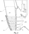
- such thermal insulation is obtained by applying a panel 10 to the casing 13 in correspondence of the low pressure turbine 21 of Fig. 1 .
- the panel can be positioned indistinguishably in correspondence of the high pressure turbine 19 or the compressor section 9 or in any combination thereof.
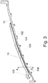
- Fig. 3 shows, in grey level shadings, the thermal behavior of a section of the case 13 of a turbine when a thermal insulation assembly 10 is applied.
- such an insulation assembly 10 comprises a panel 101 coupled to a metal sheet 102 maintained at a designed distance from the casing 13 by milling longitudinal ribs 103 on the casing. This allows to create a passage 104 for cooling air.
- ribs or protuberances 203 of the metal sheet 102 define air passage 204 between the casing 13 and the panel 101.
- Such ribs can be advantageously obtained, for example, by bending the sheet at certain points to create pins or pillars 203.
- the metal sheet is substituted by an external casing 102' welded on the main casing 13 of the turbine, for example by a brazing process.
- Welding points define spacers 303 allowing to create a passage 304 for cooling air as in previous embodiments.
- the external casing 102' can, for example, be coupled to a metal sheet 102 to improve thermal conductivity of the insulation assembly 10.
- Metal sheet 102 or external casing 102' could also be omitted in some embodiments.
- the panel 101 can be of any geometrical shape and can be applied longitudinally, circumferentially, spirally or following any suitable pattern to provide an optimized thermal management.
- the insulating panels 101 can advantageously be quilted panels encased in woven glass cloth and stitched through parallel or crosswise in distances from 25 to 100 mm in order to give flexibility in one or two dimensions.
- Thread types can include glass, aramid or stainless steel.
- the density of quilted panels is typically in the range 190 to 300 Kg/m 3 .
- the glass cloth is provided for handling purposes only and embrittles or melts at temperature below the maximum usage temperature of the insulation without affecting the insulation properties in service.
- Cooling air is impinged in the passage 104, 204, 304 through air inlet 106 by means of air manifolds 105 as best seen in Fig. 3 .
- Position and quantity of the inlet manifolds 105, air quantity and geometry of the spacer are optimized to meet case metal temperature requirement.
- Air is supplied by gas turbine axial compressor extraction or by external sources and, more in general, by a forced air-stream generator in fluid communication with an air intake plenum.
- the forced-air generator generates a stream of forced cooling air at a pressure sufficient to circulate the cooling air in the air passage to control heat dissipation.
- Air is shut-off at gas turbine shut-off.
- Outlets 107 are provided in the passage 104, 204, 304 to allow air to exit either in the external environment or in the turbine main outlet 23 to avoid heating the room containing the turbine.
- the turbine comprises one or more sensors to measure the speed of the rotor and/or the temperature in one or more areas of the aeroderivative turbine and a control unit configured to:
- the system allows to design the required thermal response both in running condition and after shut-off.
- the passage 104, 204, 304 allows the air therein to act as a thermal insulator for the turbine rotor after shut-off thus avoiding the rotor to lower its temperature too much and too quickly and possibly undergo damages. Therefore, the thermal response of the case would be made convenient with respect the thermal response of the rotor in all of the mission steps, so to drive the best clearances mitigating the risk for rotor lock and/or the risk of damaging of the parts.
Landscapes
- Engineering & Computer Science (AREA)
- Chemical & Material Sciences (AREA)
- Combustion & Propulsion (AREA)
- Mechanical Engineering (AREA)
- General Engineering & Computer Science (AREA)
- Turbine Rotor Nozzle Sealing (AREA)
- Structures Of Non-Positive Displacement Pumps (AREA)
- Organic Low-Molecular-Weight Compounds And Preparation Thereof (AREA)
- Control Of Turbines (AREA)
Claims (12)
- Aeroderivative Gasturbine, umfassend:ein Gehäuse (13);einen Verdichter mit einem Rotor (14), der auf einer Generatorwelle (16) montiert ist, die zur Drehung in dem Gehäuse (13) gelagert ist;eine Brennkammer (17);eine Hochdruckturbine (19), die in dem Gehäuse angeordnet ist und bestehend aus einem Rotor (19), der an der Generatorwelle (16) zur gemeinsamen Drehung mit dem Verdichterrotor (14) montiert ist;eine Nutzturbine (21), die in dem Gehäuse (13) angeordnet ist und einen Rotor (21 R) umfasst, der auf einer Turbinenwelle (22) montiert ist, um eine Last anzutreiben,umfassend eine Wärmeisolationsbeschichtung, die mit dem Gehäuse (13) gekoppelt ist, um Wärmedispersion durch das Gehäuse (13) zu reduzieren, wobei die Turbine dadurch gekennzeichnet ist, dass die Isolationsbeschichtung eine Isolationsanordnung (10) ist, die ein Isolationsblech oder -paneel (101) umfasst, das mit einem Metallblech (102) gekoppelt ist, das in einem ausgelegten Abstand von dem Gehäuse (13) gehalten wird, um einen Durchgang (104, 204, 304) zu erzeugen und konfiguriert ist, um Kühlluft zwischen dem Gehäuse (13) und dem Paneel (101) zirkulieren zu lassen, wenn der Rotor (21 R) in Betrieb ist, und konfiguriert ist, um der Luft innerhalb des Durchgangs (104, 204, 304) zu ermöglichen, als ein thermischer Isolator für den Rotor (21 R) zu wirken, wenn der Rotor (21 R) im Leerlauf ist.
- Turbine nach Anspruch 1, wobei die Wärmeisolationsbeschichtung (10) auf mindestens einem Teil der Außenfläche des Gehäuses (13) angeordnet ist.
- Turbine nach Anspruch 1 oder 2, wobei sich die
Isolationsbeschichtung (10) auf dem Teil des Gehäuses (13) befindet, der mindestens teilweise die Nutzturbine (21) enthält. - Turbine nach Anspruch 1, wobei das Metallblech (102) durch Längsrippen (103), die an dem Gehäuse (13) gefräst sind, auf Abstand von dem Gehäuse gehalten wird.
- Turbine nach Anspruch 1, wobei das Metallblech (102) durch Rippen oder Vorsprünge (203) des Metallblechs (102) auf Abstand von dem Gehäuse (13) gehalten wird.
- Turbine nach Anspruch 1, wobei das Metallblech (102) durch ein Außengehäuse (102 ') ersetzt oder zusätzlich dazu bereitgestellt ist, das an das Gehäuse (13) der Turbine geschweißt ist, wobei Schweißpunkte (303) zwischen dem Außengehäuse (102') und dem Gehäuse (13) angeordnet sind, um Abstandshalter zu bilden, die einen Durchgang (304) für Kühlluft zwischen dem Gehäuse (13) und dem Paneel (101) erzeugen.
- Turbine nach einem der vorstehenden Ansprüche, wobei die Isolationsanordnung (10) an dem Gehäuse (13) in Längsrichtung, in Umfangsrichtung, spiralförmig oder nach einem beliebigen geeigneten Muster angeordnet ist, um ein optimiertes Wärmemanagement bereitzustellen.
- Turbine nach einem der vorstehenden Ansprüche, wobei die Isolationsbeschichtung gesteppte Paneele umfasst, die mit Glasgewebe ummantelt und parallel oder kreuzweise in Abständen von 25 bis 100 mm durchgenäht sind.
- Turbine nach einem der vorstehenden Ansprüche, wobei die Kühlluft in dem Durchgang (104, 204, 304) durch einen Lufteinlass (106) mittels Luftverteilern (105) beaufschlagt wird.
- Turbine nach einem der vorstehenden Ansprüche, ferner umfassend einen Zwangsluftgenerator, wie eine Turbinenaxialverdichterentnahme, eine externe Quelle oder dergleichen, der einen Strom von Zwangskühlluft mit einem Druck erzeugt, der ausreicht, um die Kühlluft in dem Luftdurchgang (104, 204, 304) zirkulieren zu lassen, um die Wärmeabfuhr zu steuern.
- Turbine nach einem der vorstehenden Ansprüche, ferner umfassend einen Auslass (107) in Fluidverbindung mit dem Turbinenhauptauslass (23), um zu ermöglichen, dass die Luft den Durchgang (104, 204, 304) verlässt.
- Turbine nach einem der vorstehenden Ansprüche, ferner umfassend einen oder mehrere Sensoren zum Messen der Drehzahl des Rotors und/oder der Temperatur in einem oder mehreren Bereichen der aeroderivativen Turbine und eine Steuereinheit, die konfiguriert ist zum:Lesen der Ausgabe des Sensors oder der Sensoren;Vergleichen der Ausgabe mit Schwellenwerten, um einen Übertemperaturzustand zu bestimmen, oder Vergleichen der Ausgabe mit einem Temperaturziel in Abhängigkeit von dem Betriebszustand der aeroderivativen Turbine;Einwirken auf den Zwangsluftgenerator, um den Luftstrom in dem Durchgang (104, 204, 304) zu regulieren, um den Wärmeaustausch durch das Gehäuse zu steuern.
Applications Claiming Priority (1)
| Application Number | Priority Date | Filing Date | Title |
|---|---|---|---|
| IT102018000003136A IT201800003136A1 (it) | 2018-02-28 | 2018-02-28 | Turbina a gas aero-derivata con gestione termica migliorata |
Publications (2)
| Publication Number | Publication Date |
|---|---|
| EP3533975A1 EP3533975A1 (de) | 2019-09-04 |
| EP3533975B1 true EP3533975B1 (de) | 2021-04-21 |
Family
ID=62223118
Family Applications (1)
| Application Number | Title | Priority Date | Filing Date |
|---|---|---|---|
| EP19159056.1A Active EP3533975B1 (de) | 2018-02-28 | 2019-02-25 | Aeroderivative gasturbine mit verbessertem thermischen management |
Country Status (5)
| Country | Link |
|---|---|
| US (2) | US11933222B2 (de) |
| EP (1) | EP3533975B1 (de) |
| AU (1) | AU2019200994B2 (de) |
| CA (1) | CA3033822A1 (de) |
| IT (1) | IT201800003136A1 (de) |
Families Citing this family (1)
| Publication number | Priority date | Publication date | Assignee | Title |
|---|---|---|---|---|
| DE102023121051A1 (de) * | 2023-08-08 | 2025-02-13 | MTU Aero Engines AG | Kühlbares Turbinenmodul und erwärmbares Verdichtermodul für eine Strömungsmaschine, sowie Strömungsmaschine |
Family Cites Families (21)
| Publication number | Priority date | Publication date | Assignee | Title |
|---|---|---|---|---|
| US2705208A (en) * | 1951-04-30 | 1955-03-29 | Gen Electric | Thermal insulation blanket |
| US5131097A (en) * | 1988-11-30 | 1992-07-21 | Grilliot William L | Firefighter's garments having minimum weight and excellent protective qualities |
| US5176495A (en) * | 1991-07-09 | 1993-01-05 | General Electric Company | Thermal shielding apparatus or radiositor for a gas turbine engine |
| DE4331060C1 (de) * | 1993-09-13 | 1994-06-30 | Gruenzweig & Hartmann Montage | Wärmedämmanordnung |
| DE69422192D1 (de) * | 1993-11-03 | 2000-01-20 | Michael Graham Dawes | Verkleidung |
| WO2003008159A1 (en) * | 2001-07-17 | 2003-01-30 | Saint-Gobain Isover A/S | A method and an apparatus for producing elements by punching |
| FR2871513B1 (fr) * | 2004-06-15 | 2006-09-22 | Snecma Moteurs Sa | Systeme et procede de controle d'un flux d'air dans une turbine a gaz |
| US8181443B2 (en) * | 2008-12-10 | 2012-05-22 | Pratt & Whitney Canada Corp. | Heat exchanger to cool turbine air cooling flow |
| GB0906059D0 (en) * | 2009-04-08 | 2009-05-20 | Rolls Royce Plc | Thermal control system for turbines |
| FR2957115B1 (fr) * | 2010-03-05 | 2012-03-30 | Snecma | Etage de turbine dans une turbomachine |
| EP2518278A1 (de) * | 2011-04-28 | 2012-10-31 | Siemens Aktiengesellschaft | Kühlleitung eines Turbinengehäuses mit stromaufwärts fliessender Kühlflüssigkeit |
| US9115600B2 (en) * | 2011-08-30 | 2015-08-25 | Siemens Energy, Inc. | Insulated wall section |
| ITFI20110247A1 (it) | 2011-11-14 | 2013-05-15 | Nuovo Pignone Spa | "device and method for slow turning of an aeroderivative gas turbine" |
| ITFI20120046A1 (it) | 2012-03-08 | 2013-09-09 | Nuovo Pignone Srl | "device and method for gas turbine unlocking" |
| ITTO20120519A1 (it) * | 2012-06-14 | 2013-12-15 | Avio Spa | Turbina a gas per motori aeronautici |
| DE102013213834A1 (de) * | 2013-07-15 | 2015-02-19 | MTU Aero Engines AG | Verfahren zum Herstellen eines Isolationselements und Isolationselement für ein Gehäuse eines Flugtriebwerks |
| ES2718129T3 (es) * | 2013-07-23 | 2019-06-27 | MTU Aero Engines AG | Dispositivo de aislamiento para una turbina de gas térmica y una turbina de gas térmica con esta estructura |
| JP6223111B2 (ja) * | 2013-10-15 | 2017-11-01 | 三菱日立パワーシステムズ株式会社 | ガスタービン |
| US10975721B2 (en) * | 2016-01-12 | 2021-04-13 | Pratt & Whitney Canada Corp. | Cooled containment case using internal plenum |
| FR3067751B1 (fr) * | 2017-06-15 | 2019-07-12 | Safran Aircraft Engines | Dispositif de refroidissement d'un carter annulaire externe de turbine |
| US10508810B2 (en) * | 2017-09-19 | 2019-12-17 | Hexcel Corporation | Thermal panel with a corrugated ceramic composite sheet having unequal ridge widths |
-
2018
- 2018-02-28 IT IT102018000003136A patent/IT201800003136A1/it unknown
-
2019
- 2019-02-05 US US16/267,972 patent/US11933222B2/en active Active
- 2019-02-13 AU AU2019200994A patent/AU2019200994B2/en active Active
- 2019-02-14 CA CA3033822A patent/CA3033822A1/en active Pending
- 2019-02-25 EP EP19159056.1A patent/EP3533975B1/de active Active
-
2024
- 2024-02-14 US US18/441,398 patent/US20240183313A1/en active Pending
Non-Patent Citations (1)
| Title |
|---|
| None * |
Also Published As
| Publication number | Publication date |
|---|---|
| US11933222B2 (en) | 2024-03-19 |
| CA3033822A1 (en) | 2019-08-28 |
| US20240183313A1 (en) | 2024-06-06 |
| RU2019105414A (ru) | 2020-08-26 |
| AU2019200994B2 (en) | 2024-07-25 |
| AU2019200994A1 (en) | 2019-09-12 |
| EP3533975A1 (de) | 2019-09-04 |
| IT201800003136A1 (it) | 2019-08-28 |
| US20190264613A1 (en) | 2019-08-29 |
| BR102019004037A2 (pt) | 2019-11-05 |
Similar Documents
| Publication | Publication Date | Title |
|---|---|---|
| EP3075957B1 (de) | Wärmerohr-temperaturregelung für eine turbomaschine | |
| RU2550371C2 (ru) | Способ эксплуатации газовой турбины, система охлаждения газовой турбины и газовая турбина, содержащая такую систему | |
| EP2208862B1 (de) | Vorrichtung und Verfahren zur Kontrolle des Schaufelspitzenspiels eines Verdichters | |
| US9945266B2 (en) | Combined cycle power plant thermal energy conservation | |
| US20130139516A1 (en) | Cooling system for gas turbine load coupling | |
| CN101793269A (zh) | 利用轴承油余热的压缩机间隙控制系统 | |
| Ol’khovskii | The most powerful power-generating GTUs (a review) | |
| US20240183313A1 (en) | Aeroderivative gas turbine with improved thermal management | |
| EP2589750A2 (de) | Verfahren zur Steuerung der Gasturbinenrotortemperatur während längerer Ausfallzeiten | |
| Shepard et al. | Design and development of the WR-21 intercooled recuperated (ICR) marine gas turbine | |
| US9115600B2 (en) | Insulated wall section | |
| EP3896263B1 (de) | Thermischer kontrollring mit speichen für ein gehäuseabstandskontrollsystem eines hochdruckverdichters | |
| US20160061060A1 (en) | Combined cycle power plant thermal energy conservation | |
| MEHALIC | Effect of spatial inlet temperature and pressure distortion on turbofan engine stability | |
| CN104126065A (zh) | 燃气涡轮发动机 | |
| US20200116038A1 (en) | Diffuser flex seal assembly | |
| US20050120719A1 (en) | Internally insulated turbine assembly | |
| RU2777405C2 (ru) | Газовая турбина авиационного типа с улучшенным терморегулированием | |
| BR102019004037B1 (pt) | Turbina a gás aeroderivada | |
| EP3284917B1 (de) | Aktiver spielsteuerungskollektor für einen verteilereinsatz | |
| Ol’khovskii | Aeroderivative GTUs for Power Generation (Overview) | |
| Arai et al. | Characteristics and Applications of Hitachi H-25 Gas Turbine | |
| Hubbard et al. | Development and Field Experience of a New 29000 HP Gas Turbine | |
| Aschenbruck et al. | Development and Testing of the Upgraded High Pressure Turbine Section for an Industrial Gas Turbine | |
| CA3224045A1 (en) | DYNAMIC AIR-DRIVED BLADE CONTROL SYSTEM FOR TURBOPROPULS |
Legal Events
| Date | Code | Title | Description |
|---|---|---|---|
| PUAI | Public reference made under article 153(3) epc to a published international application that has entered the european phase |
Free format text: ORIGINAL CODE: 0009012 |
|
| STAA | Information on the status of an ep patent application or granted ep patent |
Free format text: STATUS: THE APPLICATION HAS BEEN PUBLISHED |
|
| AK | Designated contracting states |
Kind code of ref document: A1 Designated state(s): AL AT BE BG CH CY CZ DE DK EE ES FI FR GB GR HR HU IE IS IT LI LT LU LV MC MK MT NL NO PL PT RO RS SE SI SK SM TR |
|
| AX | Request for extension of the european patent |
Extension state: BA ME |
|
| STAA | Information on the status of an ep patent application or granted ep patent |
Free format text: STATUS: REQUEST FOR EXAMINATION WAS MADE |
|
| 17P | Request for examination filed |
Effective date: 20200304 |
|
| RBV | Designated contracting states (corrected) |
Designated state(s): AL AT BE BG CH CY CZ DE DK EE ES FI FR GB GR HR HU IE IS IT LI LT LU LV MC MK MT NL NO PL PT RO RS SE SI SK SM TR |
|
| GRAP | Despatch of communication of intention to grant a patent |
Free format text: ORIGINAL CODE: EPIDOSNIGR1 |
|
| STAA | Information on the status of an ep patent application or granted ep patent |
Free format text: STATUS: GRANT OF PATENT IS INTENDED |
|
| INTG | Intention to grant announced |
Effective date: 20201002 |
|
| GRAS | Grant fee paid |
Free format text: ORIGINAL CODE: EPIDOSNIGR3 |
|
| GRAA | (expected) grant |
Free format text: ORIGINAL CODE: 0009210 |
|
| STAA | Information on the status of an ep patent application or granted ep patent |
Free format text: STATUS: THE PATENT HAS BEEN GRANTED |
|
| AK | Designated contracting states |
Kind code of ref document: B1 Designated state(s): AL AT BE BG CH CY CZ DE DK EE ES FI FR GB GR HR HU IE IS IT LI LT LU LV MC MK MT NL NO PL PT RO RS SE SI SK SM TR |
|
| REG | Reference to a national code |
Ref country code: GB Ref legal event code: FG4D |
|
| REG | Reference to a national code |
Ref country code: CH Ref legal event code: EP |
|
| REG | Reference to a national code |
Ref country code: DE Ref legal event code: R096 Ref document number: 602019003960 Country of ref document: DE |
|
| REG | Reference to a national code |
Ref country code: IE Ref legal event code: FG4D |
|
| REG | Reference to a national code |
Ref country code: AT Ref legal event code: REF Ref document number: 1384841 Country of ref document: AT Kind code of ref document: T Effective date: 20210515 |
|
| REG | Reference to a national code |
Ref country code: SE Ref legal event code: TRGR |
|
| REG | Reference to a national code |
Ref country code: LT Ref legal event code: MG9D |
|
| REG | Reference to a national code |
Ref country code: AT Ref legal event code: MK05 Ref document number: 1384841 Country of ref document: AT Kind code of ref document: T Effective date: 20210421 |
|
| REG | Reference to a national code |
Ref country code: NL Ref legal event code: MP Effective date: 20210421 |
|
| REG | Reference to a national code |
Ref country code: NO Ref legal event code: T2 Effective date: 20210421 |
|
| PG25 | Lapsed in a contracting state [announced via postgrant information from national office to epo] |
Ref country code: NL Free format text: LAPSE BECAUSE OF FAILURE TO SUBMIT A TRANSLATION OF THE DESCRIPTION OR TO PAY THE FEE WITHIN THE PRESCRIBED TIME-LIMIT Effective date: 20210421 Ref country code: AT Free format text: LAPSE BECAUSE OF FAILURE TO SUBMIT A TRANSLATION OF THE DESCRIPTION OR TO PAY THE FEE WITHIN THE PRESCRIBED TIME-LIMIT Effective date: 20210421 Ref country code: BG Free format text: LAPSE BECAUSE OF FAILURE TO SUBMIT A TRANSLATION OF THE DESCRIPTION OR TO PAY THE FEE WITHIN THE PRESCRIBED TIME-LIMIT Effective date: 20210721 Ref country code: FI Free format text: LAPSE BECAUSE OF FAILURE TO SUBMIT A TRANSLATION OF THE DESCRIPTION OR TO PAY THE FEE WITHIN THE PRESCRIBED TIME-LIMIT Effective date: 20210421 Ref country code: HR Free format text: LAPSE BECAUSE OF FAILURE TO SUBMIT A TRANSLATION OF THE DESCRIPTION OR TO PAY THE FEE WITHIN THE PRESCRIBED TIME-LIMIT Effective date: 20210421 Ref country code: LT Free format text: LAPSE BECAUSE OF FAILURE TO SUBMIT A TRANSLATION OF THE DESCRIPTION OR TO PAY THE FEE WITHIN THE PRESCRIBED TIME-LIMIT Effective date: 20210421 |
|
| PG25 | Lapsed in a contracting state [announced via postgrant information from national office to epo] |
Ref country code: RS Free format text: LAPSE BECAUSE OF FAILURE TO SUBMIT A TRANSLATION OF THE DESCRIPTION OR TO PAY THE FEE WITHIN THE PRESCRIBED TIME-LIMIT Effective date: 20210421 Ref country code: PT Free format text: LAPSE BECAUSE OF FAILURE TO SUBMIT A TRANSLATION OF THE DESCRIPTION OR TO PAY THE FEE WITHIN THE PRESCRIBED TIME-LIMIT Effective date: 20210823 Ref country code: PL Free format text: LAPSE BECAUSE OF FAILURE TO SUBMIT A TRANSLATION OF THE DESCRIPTION OR TO PAY THE FEE WITHIN THE PRESCRIBED TIME-LIMIT Effective date: 20210421 Ref country code: LV Free format text: LAPSE BECAUSE OF FAILURE TO SUBMIT A TRANSLATION OF THE DESCRIPTION OR TO PAY THE FEE WITHIN THE PRESCRIBED TIME-LIMIT Effective date: 20210421 Ref country code: IS Free format text: LAPSE BECAUSE OF FAILURE TO SUBMIT A TRANSLATION OF THE DESCRIPTION OR TO PAY THE FEE WITHIN THE PRESCRIBED TIME-LIMIT Effective date: 20210821 Ref country code: GR Free format text: LAPSE BECAUSE OF FAILURE TO SUBMIT A TRANSLATION OF THE DESCRIPTION OR TO PAY THE FEE WITHIN THE PRESCRIBED TIME-LIMIT Effective date: 20210722 |
|
| REG | Reference to a national code |
Ref country code: DE Ref legal event code: R097 Ref document number: 602019003960 Country of ref document: DE |
|
| PG25 | Lapsed in a contracting state [announced via postgrant information from national office to epo] |
Ref country code: ES Free format text: LAPSE BECAUSE OF FAILURE TO SUBMIT A TRANSLATION OF THE DESCRIPTION OR TO PAY THE FEE WITHIN THE PRESCRIBED TIME-LIMIT Effective date: 20210421 Ref country code: EE Free format text: LAPSE BECAUSE OF FAILURE TO SUBMIT A TRANSLATION OF THE DESCRIPTION OR TO PAY THE FEE WITHIN THE PRESCRIBED TIME-LIMIT Effective date: 20210421 Ref country code: SK Free format text: LAPSE BECAUSE OF FAILURE TO SUBMIT A TRANSLATION OF THE DESCRIPTION OR TO PAY THE FEE WITHIN THE PRESCRIBED TIME-LIMIT Effective date: 20210421 Ref country code: RO Free format text: LAPSE BECAUSE OF FAILURE TO SUBMIT A TRANSLATION OF THE DESCRIPTION OR TO PAY THE FEE WITHIN THE PRESCRIBED TIME-LIMIT Effective date: 20210421 Ref country code: SM Free format text: LAPSE BECAUSE OF FAILURE TO SUBMIT A TRANSLATION OF THE DESCRIPTION OR TO PAY THE FEE WITHIN THE PRESCRIBED TIME-LIMIT Effective date: 20210421 Ref country code: CZ Free format text: LAPSE BECAUSE OF FAILURE TO SUBMIT A TRANSLATION OF THE DESCRIPTION OR TO PAY THE FEE WITHIN THE PRESCRIBED TIME-LIMIT Effective date: 20210421 Ref country code: DK Free format text: LAPSE BECAUSE OF FAILURE TO SUBMIT A TRANSLATION OF THE DESCRIPTION OR TO PAY THE FEE WITHIN THE PRESCRIBED TIME-LIMIT Effective date: 20210421 |
|
| PLBE | No opposition filed within time limit |
Free format text: ORIGINAL CODE: 0009261 |
|
| STAA | Information on the status of an ep patent application or granted ep patent |
Free format text: STATUS: NO OPPOSITION FILED WITHIN TIME LIMIT |
|
| 26N | No opposition filed |
Effective date: 20220124 |
|
| PG25 | Lapsed in a contracting state [announced via postgrant information from national office to epo] |
Ref country code: IS Free format text: LAPSE BECAUSE OF FAILURE TO SUBMIT A TRANSLATION OF THE DESCRIPTION OR TO PAY THE FEE WITHIN THE PRESCRIBED TIME-LIMIT Effective date: 20210821 Ref country code: AL Free format text: LAPSE BECAUSE OF FAILURE TO SUBMIT A TRANSLATION OF THE DESCRIPTION OR TO PAY THE FEE WITHIN THE PRESCRIBED TIME-LIMIT Effective date: 20210421 |
|
| PG25 | Lapsed in a contracting state [announced via postgrant information from national office to epo] |
Ref country code: IT Free format text: LAPSE BECAUSE OF FAILURE TO SUBMIT A TRANSLATION OF THE DESCRIPTION OR TO PAY THE FEE WITHIN THE PRESCRIBED TIME-LIMIT Effective date: 20210421 |
|
| PG25 | Lapsed in a contracting state [announced via postgrant information from national office to epo] |
Ref country code: MC Free format text: LAPSE BECAUSE OF FAILURE TO SUBMIT A TRANSLATION OF THE DESCRIPTION OR TO PAY THE FEE WITHIN THE PRESCRIBED TIME-LIMIT Effective date: 20210421 |
|
| REG | Reference to a national code |
Ref country code: BE Ref legal event code: MM Effective date: 20220228 |
|
| PG25 | Lapsed in a contracting state [announced via postgrant information from national office to epo] |
Ref country code: LU Free format text: LAPSE BECAUSE OF NON-PAYMENT OF DUE FEES Effective date: 20220225 |
|
| PG25 | Lapsed in a contracting state [announced via postgrant information from national office to epo] |
Ref country code: FR Free format text: LAPSE BECAUSE OF NON-PAYMENT OF DUE FEES Effective date: 20220228 |
|
| PG25 | Lapsed in a contracting state [announced via postgrant information from national office to epo] |
Ref country code: IE Free format text: LAPSE BECAUSE OF NON-PAYMENT OF DUE FEES Effective date: 20220225 |
|
| PG25 | Lapsed in a contracting state [announced via postgrant information from national office to epo] |
Ref country code: BE Free format text: LAPSE BECAUSE OF NON-PAYMENT OF DUE FEES Effective date: 20220228 |
|
| P01 | Opt-out of the competence of the unified patent court (upc) registered |
Effective date: 20230526 |
|
| PG25 | Lapsed in a contracting state [announced via postgrant information from national office to epo] |
Ref country code: MK Free format text: LAPSE BECAUSE OF FAILURE TO SUBMIT A TRANSLATION OF THE DESCRIPTION OR TO PAY THE FEE WITHIN THE PRESCRIBED TIME-LIMIT Effective date: 20210421 Ref country code: CY Free format text: LAPSE BECAUSE OF FAILURE TO SUBMIT A TRANSLATION OF THE DESCRIPTION OR TO PAY THE FEE WITHIN THE PRESCRIBED TIME-LIMIT Effective date: 20210421 |
|
| PG25 | Lapsed in a contracting state [announced via postgrant information from national office to epo] |
Ref country code: HU Free format text: LAPSE BECAUSE OF FAILURE TO SUBMIT A TRANSLATION OF THE DESCRIPTION OR TO PAY THE FEE WITHIN THE PRESCRIBED TIME-LIMIT; INVALID AB INITIO Effective date: 20190225 |
|
| PG25 | Lapsed in a contracting state [announced via postgrant information from national office to epo] |
Ref country code: MT Free format text: LAPSE BECAUSE OF FAILURE TO SUBMIT A TRANSLATION OF THE DESCRIPTION OR TO PAY THE FEE WITHIN THE PRESCRIBED TIME-LIMIT Effective date: 20210421 |
|
| PG25 | Lapsed in a contracting state [announced via postgrant information from national office to epo] |
Ref country code: TR Free format text: LAPSE BECAUSE OF FAILURE TO SUBMIT A TRANSLATION OF THE DESCRIPTION OR TO PAY THE FEE WITHIN THE PRESCRIBED TIME-LIMIT Effective date: 20210421 |
|
| REG | Reference to a national code |
Ref country code: CH Ref legal event code: U11 Free format text: ST27 STATUS EVENT CODE: U-0-0-U10-U11 (AS PROVIDED BY THE NATIONAL OFFICE) Effective date: 20260301 |
|
| PGFP | Annual fee paid to national office [announced via postgrant information from national office to epo] |
Ref country code: SE Payment date: 20260121 Year of fee payment: 8 |
|
| PGFP | Annual fee paid to national office [announced via postgrant information from national office to epo] |
Ref country code: GB Payment date: 20260122 Year of fee payment: 8 |
|
| PGFP | Annual fee paid to national office [announced via postgrant information from national office to epo] |
Ref country code: NO Payment date: 20260123 Year of fee payment: 8 Ref country code: DE Payment date: 20260121 Year of fee payment: 8 |
|
| PGFP | Annual fee paid to national office [announced via postgrant information from national office to epo] |
Ref country code: CH Payment date: 20260301 Year of fee payment: 8 |