EP3533736A1 - Component supply device and control method for component supply device - Google Patents
Component supply device and control method for component supply device Download PDFInfo
- Publication number
- EP3533736A1 EP3533736A1 EP16919755.5A EP16919755A EP3533736A1 EP 3533736 A1 EP3533736 A1 EP 3533736A1 EP 16919755 A EP16919755 A EP 16919755A EP 3533736 A1 EP3533736 A1 EP 3533736A1
- Authority
- EP
- European Patent Office
- Prior art keywords
- movable plate
- storage hole
- state
- hole
- plate
- Prior art date
- Legal status (The legal status is an assumption and is not a legal conclusion. Google has not performed a legal analysis and makes no representation as to the accuracy of the status listed.)
- Granted
Links
Images




Classifications
-
- B—PERFORMING OPERATIONS; TRANSPORTING
- B65—CONVEYING; PACKING; STORING; HANDLING THIN OR FILAMENTARY MATERIAL
- B65G—TRANSPORT OR STORAGE DEVICES, e.g. CONVEYORS FOR LOADING OR TIPPING, SHOP CONVEYOR SYSTEMS OR PNEUMATIC TUBE CONVEYORS
- B65G47/00—Article or material-handling devices associated with conveyors; Methods employing such devices
- B65G47/02—Devices for feeding articles or materials to conveyors
- B65G47/04—Devices for feeding articles or materials to conveyors for feeding articles
- B65G47/12—Devices for feeding articles or materials to conveyors for feeding articles from disorderly-arranged article piles or from loose assemblages of articles
- B65G47/14—Devices for feeding articles or materials to conveyors for feeding articles from disorderly-arranged article piles or from loose assemblages of articles arranging or orientating the articles by mechanical or pneumatic means during feeding
- B65G47/1407—Devices for feeding articles or materials to conveyors for feeding articles from disorderly-arranged article piles or from loose assemblages of articles arranging or orientating the articles by mechanical or pneumatic means during feeding the articles being fed from a container, e.g. a bowl
- B65G47/1442—Devices for feeding articles or materials to conveyors for feeding articles from disorderly-arranged article piles or from loose assemblages of articles arranging or orientating the articles by mechanical or pneumatic means during feeding the articles being fed from a container, e.g. a bowl by means of movement of the bottom or a part of the wall of the container
- B65G47/145—Jigging or reciprocating movement
-
- B—PERFORMING OPERATIONS; TRANSPORTING
- B65—CONVEYING; PACKING; STORING; HANDLING THIN OR FILAMENTARY MATERIAL
- B65G—TRANSPORT OR STORAGE DEVICES, e.g. CONVEYORS FOR LOADING OR TIPPING, SHOP CONVEYOR SYSTEMS OR PNEUMATIC TUBE CONVEYORS
- B65G47/00—Article or material-handling devices associated with conveyors; Methods employing such devices
- B65G47/02—Devices for feeding articles or materials to conveyors
- B65G47/04—Devices for feeding articles or materials to conveyors for feeding articles
- B65G47/12—Devices for feeding articles or materials to conveyors for feeding articles from disorderly-arranged article piles or from loose assemblages of articles
-
- B—PERFORMING OPERATIONS; TRANSPORTING
- B65—CONVEYING; PACKING; STORING; HANDLING THIN OR FILAMENTARY MATERIAL
- B65G—TRANSPORT OR STORAGE DEVICES, e.g. CONVEYORS FOR LOADING OR TIPPING, SHOP CONVEYOR SYSTEMS OR PNEUMATIC TUBE CONVEYORS
- B65G47/00—Article or material-handling devices associated with conveyors; Methods employing such devices
- B65G47/74—Feeding, transfer, or discharging devices of particular kinds or types
- B65G47/78—Troughs having discharge openings and closures
-
- B—PERFORMING OPERATIONS; TRANSPORTING
- B65—CONVEYING; PACKING; STORING; HANDLING THIN OR FILAMENTARY MATERIAL
- B65G—TRANSPORT OR STORAGE DEVICES, e.g. CONVEYORS FOR LOADING OR TIPPING, SHOP CONVEYOR SYSTEMS OR PNEUMATIC TUBE CONVEYORS
- B65G65/00—Loading or unloading
- B65G65/30—Methods or devices for filling or emptying bunkers, hoppers, tanks, or like containers, of interest apart from their use in particular chemical or physical processes or their application in particular machines, e.g. not covered by a single other subclass
- B65G65/34—Emptying devices
- B65G65/40—Devices for emptying otherwise than from the top
- B65G65/48—Devices for emptying otherwise than from the top using other rotating means, e.g. rotating pressure sluices in pneumatic systems
- B65G65/4809—Devices for emptying otherwise than from the top using other rotating means, e.g. rotating pressure sluices in pneumatic systems rotating about a substantially vertical axis
-
- B—PERFORMING OPERATIONS; TRANSPORTING
- B65—CONVEYING; PACKING; STORING; HANDLING THIN OR FILAMENTARY MATERIAL
- B65G—TRANSPORT OR STORAGE DEVICES, e.g. CONVEYORS FOR LOADING OR TIPPING, SHOP CONVEYOR SYSTEMS OR PNEUMATIC TUBE CONVEYORS
- B65G2814/00—Indexing codes relating to loading or unloading articles or bulk materials
- B65G2814/03—Loading or unloading means
- B65G2814/0301—General arrangements
- B65G2814/0314—General arrangements for moving bulk material downwards
- B65G2814/0319—General arrangements for moving bulk material downwards through a closable or non-closable outlet opening
- B65G2814/0325—General arrangements for moving bulk material downwards through a closable or non-closable outlet opening with rotating drums, cylinders or cones in or beneath the opening
Definitions
- the invention relates to a component supply device and a control method thereof.
- a work operation using a component such as a clip or a grommet is performed by taking out only a predetermined number of components to be used in the work operation from a hopper in which many components are stored in advance.
- a hopper in which many components are stored in advance.
- unnecessary components are returned to the hopper, and when the number of components is smaller than the number of components to be used, a necessary number of components are taken out from the hopper. In either case, useless work operations should be performed.
- JP 2013-103792 A discloses a component supply device configured to output only a predetermined number of components to be used so as to restrain such useless work operations.
- the component supply device is configured such that a component is supplied, via an inclined supply pipe, from a housing portion in which a lot of components are stored to an output groove provided in the outer periphery of a rotating disk, and in a state where the component stays in the output groove, the rotating disk rotates, so that the component is moved to a discharge port to the outside. Further, in a case where the components have a complicated shape, there is such a problem that the components get entangled.
- the component supply device in the literature includes, as a mechanism for breaking off the entanglement between the components, an excitation rod configured to vibrate in the up-down direction inside the housing portion, and a stirring rod provided on a front surface of the rotating disk.
- the entanglement is broken in such a manner that vertical vibrations are given by the excitation rod to the components stored in the housing portion. Accordingly, in a state where a large number of components are stored in the housing portion, the entanglement is hard to be broken, and this might cause deformation or breakage of the components. Further, even in a case where the entanglement is broken by the excitation rod and the stirring rod, if a plurality of components stays in the output groove, a greater number of components than the predetermined number are output.
- the invention is intended to provide a component supply device that can output only a predetermined number of components to be used in a work operation, and a control method thereof.
- a component supply device configured to output a predetermined number of components to be used in a work operation
- the component supply device comprises a fixing plate having a via-hole through which the components pass, the fixing plate being fixed to a housing, and a movable plate having a storage hole penetrating through the movable plate in an up-down direction and having a size that allows the predetermined number of components to be stored, the movable plate being laminated on a top side of the fixing plate and configured to move such that the storage hole moves relative to the via-hole in a direction parallel to a top face of the fixing plate.
- the component supply device further comprises a controlling portion configured to control an operation of the movable plate and an elastic member placed on a top side of the movable plate and configured to elastically deform in a direction parallel to a top face of the movable plate.
- the controlling portion repeatedly performs the following operations until the predetermined number of components are output, a forward-direction operation of moving the movable plate from a first state in which a top side of the storage hole is opened and a bottom side of the storage hole is closed by the fixing plate to a second state in which the storage hole communicates with the via-hole and the components are movable from the storage hole to the via-hole, and a reverse-direction operation of returning the movable plate to the first state by reversing a moving direction of the movable plate when the movable plate enters the second state.
- the elastic member hits the component to remove the projecting component from the storage hole before the movable plate enters the second state, or the elastic member elastically deforms by being pressed by the projecting component, so that, while the movable plate is in the second state, the projecting component is sandwiched between the elastic member and a wall surface of the storage hole due to an elastic force caused by the elastic deformation.
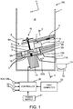
- FIG. 1 is a sectional view illustrating a configuration of a component supply device 100 according to a first embodiment.
- FIG. 2 is a sectional view of the component supply device 100 taken along a line II-II in FIG. 1 .
- the x-axis direction is assumed to be the lateral direction
- the y-axis direction is assumed to be the up-down direction unless otherwise specified.
- a component (also referred to as "workpiece") output from the component supply device 100 in the present embodiment is a resin clip W to be used in a step of attaching a trim component and the like to a vehicle body in an assembly line for automobiles.
- FIG. 3 is a side view illustrating an example of the clip W.
- FIG. 4 is a top plan view of the clip W. Further, the "longitudinal dimension" and the “radial dimension” of the clip W to be used in the following description are as illustrated in FIGS. 3, 4 .
- component supply device 100 of the present embodiment is also usable for a grommet, a bolt, a nut, and the like other than the resin clip W described above.
- a housing 1 of the component supply device 100 is formed in a box shape opened upward. Note that a cover for opening and closing an upper opening 4A may be provided.
- a fixing plate 2 is fixed to an inner side wall of the housing 1 in an inclined manner.
- the fixing plate 2 has a via-hole 2A penetrating through the fixing plate 2 from its top face to its bottom face and having a size that allows the clip W to pass through the via-hole 2A. Further, the fixing plate 2 also has a hole through which a rotary shaft of a stepping motor 13 (described later) penetrates.
- a rotating disk 3 as a movable plate, and a disk enclosure 17 having a top face flush with a top face of the rotating disk 3 are laminated.
- the disk enclosure 17 is fixed to the inner side wall of the housing 1 in an inclined manner, similarly to the fixing plate 2.
- the disk enclosure 17 has a through-hole having the same shape as the rotating disk 3, and the rotating disk 3 is placed in the through-hole.
- the disk enclosure 17 includes a position sensor 16 configured to detect a zero-degree position of the rotating disk 3 as will be described below.
- the rotating disk 3 is connected to the rotary shaft of the stepping motor 13 via a fixation collar 10 and rotates by a driving force of the stepping motor 13.
- the rotating disk 3 is connected to the stepping motor 13 such that the rotating axis of the rotating disk 3 and the rotary shaft of the stepping motor 13 are placed coaxially.
- a stirring shaft 9 is fixed to the top face of the rotating disk 3 such that its rotating axis corresponds to the rotary shaft of the stepping motor 13.
- the stirring shaft 9 includes a stirring plate 8 provided near a distal end of the stirring shaft 9 so as to extend in a direction perpendicular to the axial direction of the stirring shaft 9.
- the stirring shaft 9 and the stirring plate 8 constitute an agitator 19.
- the thickness of the rotating disk 3 in the up-down direction is equivalent to or larger than the longitudinal dimension of the clip W. However, the thickness of the rotating disk 3 in the up-down direction is smaller than twice the longitudinal dimension of the clip W.
- the rotating disk 3 has a pair of storage holes 3A.
- the storage holes 3A are columnar holes penetrating through the rotating disk 3 in the up-down direction.
- the inside diameter of the storage hole 3A is equivalent to or larger than the radial dimension of the clip W. However, the inside diameter of the storage hole 3A is smaller than twice the radial dimension.
- the pair of storage holes 3A is provided at an interval of 180 degrees in the circumferential direction of the rotating disk 3. Further, the opening area of the via-hole 2A is equivalent to or larger than the opening area of the storage hole 3A.
- the via-hole 2A is disposed such that the loci of the openings of the pair of the storage holes 3A at the time when the rotating disk 3 rotates pass the opening of the via-hole 2A, when viewed from above.
- the reason why the thickness of the rotating disk 3 and the inside diameter of the storage hole 3A are set as described above is to cause one of two clips W to partially project from the top face of the storage hole 3A when the two clips W enter the storage hole 3A.
- a stopper 5 is laminated on a top side of the rotating disk 3.
- the stopper 5 is supported by the housing 1 via a spring 6.
- the stopper 5 and the spring 6 form an elastic member.
- the stopper 5 is placed above the via-hole 2A and is also placed on the loci of the openings of two storage holes 3A at the time when the rotating disk 3 rotates, when viewed from above.
- the stopper 5 of the present embodiment has a cylindrical shape with a diameter equivalent to or larger than the inside diameter of the storage hole 3A but not larger than about twice the inside diameter.
- a space retainer plate 4 is fixed to an inner wall surface of the housing 1 in an inclined state similarly to the fixing plate 2, the rotating disk 3, and the disk enclosure 17.
- An opening 4A is provided between a lowest-side end of the space retainer plate 4 in the vertical direction and the inner wall surface of the housing 1.
- the space retainer plate 4 is made of a transparent acrylic board. Since the space retainer plate 4 is transparent, a state below the space retainer plate 4 can be easily viewed, and when abnormality or the like occurs in movement of the rotating disk 3, for example, it is possible to deal with the abnormality immediately.
- a weight plate 7 is disposed between a bottom face of the space retainer plate 4 and a top face of the stopper 5.
- the weight plate 7 is configured to restrict the moving direction of the stopper 5 so that the stopper 5 moves along the top face of the disk enclosure 17. Note that, in a case where the elastic member has a configuration different from the present embodiment and the moving direction of a part corresponding to the stopper 5 can be directly restricted by the space retainer plate 4, the weight plate 7 is not an essential constituent.
- a slider 11 via which the via-hole 2A communicates with the outside of the housing 1 is disposed on a bottom side of the fixing plate 2.
- Two workpiece count sensors 12A, 12B are disposed on the slider 11.
- Each of the workpiece count sensors 12A, 12B is constituted by a light-emitting element and a light-receiving element provided in a pair so as to sandwich the slider 11 and is configured to detect that the clip W has passed when the clip W has passed between the light-emitting element and the light-receiving element to block light.
- the two workpiece count sensors 12A, 12B are disposed at a predetermined interval in a direction where the clip W flows. Then, when at least one of the two workpiece count sensors 12A, 12B detects that the clip W has passed in a predetermined time set in advance, a controller 20 (described below) performs count-up.
- a tray 14 configured to receive the clip W output via the slider 11, and a weight sensor (hereinafter referred to as "workpiece check sensor") 15 configured to determine whether the clip W is put in the tray 14 or not are disposed outside the housing 1 and below an outlet 11A of the slider 11.
- workpiece check sensor a weight sensor
- the controller 20 reads information from a host computer 22 and signals from the workpiece count sensors 12A, 12B, the position sensor 16, and the workpiece check sensor 15, and controls driving of the stepping motor 13. Details of the control will be described later. Note that the controller 20 and the stepping motor 13 are operated by electric power supplied from a power supply 21.
- controller 20 is constituted by a microcomputer including a central processing unit (CPU), a read only memory (ROM), a random access memory (RAM), and an input-output interface (I/O interface).
- the controller 20 can be constituted by a plurality of microcomputers.
- FIG. 5 is a view of the rotating disk 3, the disk enclosure 17, and the stopper 5 viewed from above. Note that, in order to distinguish the two storage holes 3A from each other, they are referred to as a first storage hole 3A-1 and a second storage hole 3A-2, respectively.
- the first storage hole 3A-1 is placed on an opposite side from the stopper 5 across the rotation center of the rotating disk 3 as illustrated in FIG. 5(a) .
- the second storage hole 3A-2 is placed below the stopper 5. This state is referred to as a zero position. Note that, in a case where the rotating disk 3 deviates from the zero position at the time of the operation start, the controller 20 starts the operation after performing zero-position adjustment to return the rotating disk 3 to the zero position.
- the zero-position adjustment is performed based on a detection value of the position sensor 16 as a starting position check sensor.
- a mark such as a notch or a projection is provided in the rotating disk 3, and by disposing the position sensor 16 at a position facing the mark at the time when the rotating disk 3 is placed at the zero position, it is possible to detect whether the rotating disk 3 is placed at the zero position or not.
- the rotating disk 3 rotates counterclockwise in the figure as illustrated in FIG. 5(b) . Then, as illustrated in FIG. 5(c) , when the rotating disk 3 rotates by 180 degrees and the first storage hole 3A-1 reaches above the via-hole 2A, the rotating disk 3 stops rotating. After that, as illustrated in FIG. 5(d) , the rotating disk 3 reverses its rotation direction and rotates clockwise in the figure by 180 degrees, so that the rotating disk 3 returns to the zero position. Hereafter, this operation is performed repeatedly.
- the rotating disk 3 includes two storage holes 3A, but the rotating disk 3 may include one storage hole 3A.
- the rotating disk 3 includes only the first storage hole 3A-1. That is, at the zero position, the rotating disk 3 enters a first state in which a top side of the first storage hole 3A-1 is opened and a bottom side thereof is closed by the fixing plate 2, and when the rotating disk 3 rotates by 180 degrees, the rotating disk 3 enters a second state in which the first storage hole 3A-1 communicates with the via-hole 2A and the clip W is movable from the first storage hole 3A-1 to the via-hole 2A
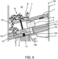
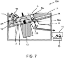
- FIGS. 6 , 7 are sectional views similar to FIG. 1 .
- the clip W stored in the second storage hole 3A-2 is output via the via-hole 2A and the slider 11. This operation is repeated until a necessary number of clips W to be used for a work operation are output. Further, inside the housing portion 18, the clips W are stirred by the stirring plate 8 rotationally driven by the stepping motor 13. Hereby, entanglement between the clips is broken.
- the clip W is stored in the storage hole 3A by use of the deadweight of the clip W.
- the size of the storage hole 3A should be made slightly larger than the size of the clip W.
- the following state may occur. That is, although one clip W is present in the storage hole 3A, another clip W may further enter an excessive space in the storage hole 3A, and the clip W entering afterward may partially project from the top face of the rotating disk 3.
- the clips W can be output one by one as described below.
- FIG. 8 is a view to describe the operation when an excessive clip W enters the storage hole 3A. Note that FIG. 8 is a view enlarging a part around the via-hole 2A in FIGS. 6 , 7 .
- the reason why the clip W can be sandwiched as described above is that the moving direction of the stopper 5 is restricted by the weight plate 7 to a direction parallel to the top face of the rotating disk 3.
- the storage hole 3A reaches above the via-hole 2A in the state where the clip W is sandwiched, only the clip W stored first in the storage hole 3A passes through the via-hole 2A as illustrated in FIG. 8(c) .
- the elastic force of the spring 6 gradually decreases, and the sandwiched clip W eventually falls into the storage hole 3A as illustrated in FIG. 8(d) .
- the clip W thus falling into the storage hole 3A is output via the via-hole 2A and the slider 11, when the rotation direction of the rotating disk 3 is reversed again and the storage hole 3A reaches above the via-hole 2A.
- the excessive clip W can be removed by the stopper 5 or the excessive clip W can be sandwiched between the stopper 5 and a wall surface of the storage hole 3A, so that the clips W can be output one by one.
- the elastic force of the spring 6 continues increasing even after the storage hole 3A passes above the via-hole 2A.
- the stopper 5 is to return to its original position due to the elastic force.
- the sandwiched clip W is flicked by the stopper 5, so that the clip W is not stored in the storage hole 3A.
- the elastic force decreases as the storage hole 3A is distanced from the stopper 5, and when the distance between the storage hole 3A and the stopper 5 becomes a size with which the clip W cannot be sandwiched, the elastic force becomes zero, so that the clip W easily falls into the storage hole 3A.
- the storage hole 3A is set to a size that causes one of two clips W to project from the top face of the rotating disk 3 when the two clips W enter the storage hole 3A, and the stopper 5 configured to clear out the projecting clip W or cause the projecting clip W to be sandwiched between the stopper 5 and the wall surface of the storage hole 3A is provided.
- the clips W can be output one by one via the via-hole 2A and the slider 11.
- a force that biases the clip W when the clip W is sandwiched between the stopper 5 and the wall surface of the storage hole 3A is the elastic force of the spring 6.
- the spring 6 is configured to have a size that allows the clip W to be sandwiched without deforming or damaging the clip W and without dropping the clip W.
- the present embodiment describes an example in which the stopper 5 and the spring 6 constitute the elastic member, but the present embodiment is not limited to this.
- the stopper 5 may be made of a member having elasticity, and the stopper 5 may be supported by just a bar-shaped member.
- a configuration that yields the above effect may be constituted by only a member having an elastic force such as a rubber or a leaf spring.
- FIG. 9 is a flowchart of a control routine executed by the controller 20. This control routine is programed in advance by the controller 20. The following describes the control routine in accordance with steps.
- step S100 the controller 20 sets the number of components to be used in a current work operation, that is, the number (hereinafter also referred to as "predetermined number") of clips W to be output this time. More specifically, a predetermined number for each type of a vehicle is stored in advance in the controller 20, and the controller 20 reads a type of a vehicle to be assembled from the host computer 22 managing an entire vehicle assembly line and sets a predetermined number corresponding to the type of the vehicle.
- step S110 the controller 20 determines whether or not an assembling target is set at a work position, and when the assembling target is set, the controller 20 executes a process of step S120.
- the determination on whether or not the assembling target is set is performed based on a detection value from a sensor (not shown) provided at the work position.
- step S120 the controller 20 determines whether or not a clip W is present in the tray 14, based on a signal from the workpiece check sensor 15, and when no clip W is present in the tray 14, the controller 20 executes a process of step S130, but when a clip W is present in the tray 14, the controller 20 repeats the determination.
- step S130 the controller 20 executes the zero-position adjustment.
- step S140 the controller 20 performs an output operation and starts count-up of the number of output clips.
- the output operation is to repeat the operation in which the rotating disk 3 is rotated counterclockwise from the zero position by 180 degrees, and then, the rotation direction is reversed to rotate the rotating disk 3 by 180 degrees, as described above with reference to FIG. 5 .
- step S150 the controller 20 determines whether the number of clips thus counted (a counter value) reaches the predetermined number or not. When the number of clips reaches the predetermined number, the controller 20 executes processes of step S160 and its subsequent steps, and when the number of clips does not reach the predetermined number, the controller 20 repeats the determination.
- step S160 the controller 20 stops the rotation of the stepping motor 13, and in step S170, the controller 20 turns on a completion lamp that informs an operator that the predetermined number of clips have been output.
- step S180 the controller 20 determines, in step S180, that there is no clip W in the tray 14, that is, when the controller 20 determines that the operator has taken out the clip W from the tray 14, the controller 20 turns off the completion lamp in step S190 and resets the counter in step S200 to finish this routine.
- the component supply device 100 outputs only the predetermined number of clips W from the housing portion 18.
- FIG. 10 is a view to describe a first modification.
- FIG. 10 illustrates only the stopper 5 and the spring 6 as the elastic member, the fixing plate 2, and a movable board 30 as the movable plate.
- the movable board 30 is used instead of the rotating disk 3 and the disk enclosure 17.
- the housing 1, the slider 11, the space retainer plate 4, and so on are configured in a similar manner to those in FIGS. 1 , 2 .
- the movable board 30 reciprocates linearly.
- the movable board 30 is driven by the stepping motor 13 via a mechanism of a rack and a pinion, or the like.
- the movable board 30 In an initial state, as illustrated in FIG. 10(a) , the movable board 30 is placed near a lower side end of the inclined fixing plate 2, and here, the clip W enters a storage hole 30A by deadweight. As illustrated in FIG. 10(b) , the movable board 30 moves along the top face of the fixing plate 2 until the storage hole 30A reaches the via-hole 2A. Then, the clip W falls from the storage hole 30A and passes through the via-hole 2A. After that, the movable board 30 reverses its travelling direction and moves back to the initial state. This operation is repeated afterward until a predetermined number of clips W are output.
- a basic configuration is the same as the configuration illustrated in FIGS. 1 , 2 , and so on.
- the size of the storage hole 3A is a size that allows the storage hole 3A to receive a plurality of clips W and is a size that causes an excessive clip W to partially project from the top face of the rotating disk 3 when more clips W than the above enter the storage hole 3A.
- the excessive clip W is removed by the stopper 5 or is sandwiched between the stopper 5 and the wall surface of the storage hole 30A, so that the plurality of clips W, the number of which is set in advance, can be output at a time.
- the plurality of clips W when the plurality of clips W is output at a time like this modification, the plurality of clips W may pass through the workpiece count sensors 12A, 12B at the same time or in an extremely short time. In such a case, it is difficult to exactly detect the number of clips W that have passed through the workpiece count sensors 12A, 12B.
- the weight hereinafter also referred to as "unit weight"
- the controller 20 determines that the predetermined number of clips W have been output.
- the fixing plate 2, the rotating disk 3, and so on that are inclined in FIG. 1 , etc. are disposed horizontally. Even in this case, the clip W enters the storage hole 3A by deadweight, so that the same effect as the above embodiment is yielded.
- the clip W falling from the housing portion 18 or the clip W removed from the storage hole 3A by the stopper 5 easily gathers on a lower side on an inclined surface and easily enters the storage hole 3A.
- the component supply device 100 of the present embodiment includes the fixing plate 2 having the via-hole 2A through which the clip W (a component) passes, the fixing plate 2 being fixed to an inner part of the housing 1, and the rotating disk (movable plate) 3 having the storage hole 3A penetrating through the rotating disk 3 in the up-down direction and having a size that allows the clip W to be stored in the storage hole 3A, the rotating disk 3 being laminated on the top side of the fixing plate 2 and configured such that the storage hole 3A moves relative to the via-hole 2A in a direction parallel to the top face of the fixing plate 2.
- the component supply device 100 includes the controller (controlling portion) 20 configured to control the operation of the rotating disk 3, and the stopper 5 and the spring 6 as the elastic member disposed on the top side of the rotating disk 3 and configured to elastically deform in a direction parallel to the top face of the rotating disk 3.
- the controller 20 repeatedly performs the following operations until the predetermined number of clips W are output: a forward-direction operation of moving the rotating disk 3 from the first state in which the top side of the storage hole 3A is opened and the bottom side thereof is closed by the fixing plate 2 to the second state in which the storage hole 3A communicates with the via-hole 2A and the clip W is movable from the storage hole 3A to the via-hole 2A; and a reverse-direction operation of returning the rotating disk 3 to the first state by reversing the moving direction of the rotating disk 3 when the rotating disk 3 enters the second state.
- the elastic member removes the projecting clip W from the storage hole 3A before the rotating disk 3 enters the second state, or the elastic member elastically deforms by being pressed by the projecting clip W to cause an elastic force by which the projecting clip W is sandwiched between the elastic member and the wall surface of the storage hole 3A while the rotating disk 3 is in the second state.
- the component supply device 100 can output the clips W one by one.
- the clip W projecting from the storage hole 3A is sandwiched between the stopper 5 and the wall surface of the storage hole 3A due to the elastic force of the spring 6, and when the rotating disk 3 is returned from the second state to the first state, the elastic force is canceled, so that the clip W is stored in the storage hole 3A. Accordingly, the clip W is efficiently stored in the storage hole 3A without being damaged.
- the component supply device 100 of the present embodiment further includes the space retainer plate 4 disposed inside the housing 1 so as to be fixed above the stopper 5, and a communication portion via which a part above the space retainer plate 4 communicates with a part below the space retainer plate 4.
- a space where the stopper 5 moves is secured, so that a large number of clips W can be put into the housing portion 18.
- the fixing plate 2, the rotating disk 3, the disk enclosure 17, and so on are inclined such that the position of the storage hole 3A in the vertical direction becomes higher in the second state than in the first state, and the space retainer plate 4 is inclined in the same direction as the fixing plate 2 and the rotating disk 3.
- the clips W gather at a low position and easily enter the storage hole 3A. Further, the clips W put into the housing portion 18 easily move to the opening 4A.
- a rotation angle of the rotating disk 3 from the first state to the second state is 180°, and the rotating disk 3 has the first storage hole 3A-1 and the second storage hole 3A-2 entering the second state when the first storage hole 3A-1 is in the first state.
- the clip W can be more efficiently output as compared to a case where only one storage hole 3A is provided.
- the controller 20 performs position adjustment (the zero-position adjustment) to adjust the rotating disk 3 to enter the first state before the rotating disk 3 starts working.
- position adjustment the zero-position adjustment
- the rotating disk 3 starts working in that state, either one of the storage holes 3A does not reach above the via-hole 2A, so that the either one of the storage holes 3A cannot function to output the clip W.
- the rotating disk 3 starts working after the zero-position adjustment is performed, so that the clips W can be output from the two storage holes 3A.
- the component supply device 100 of the present embodiment includes the agitator 19 on the top side of the space retainer plate 4. Hereby, even if many clips W are put into the housing portion 18, entanglement between clips can be broken.
Landscapes
- Engineering & Computer Science (AREA)
- Mechanical Engineering (AREA)
- Feeding Of Articles To Conveyors (AREA)
- Automatic Assembly (AREA)
- Filling Or Emptying Of Bunkers, Hoppers, And Tanks (AREA)
Abstract
Description
- The invention relates to a component supply device and a control method thereof.
- In a production process, a work operation using a component such as a clip or a grommet is performed by taking out only a predetermined number of components to be used in the work operation from a hopper in which many components are stored in advance. However, when the number of components thus taken out is larger than the number of components to be used, unnecessary components are returned to the hopper, and when the number of components is smaller than the number of components to be used, a necessary number of components are taken out from the hopper. In either case, useless work operations should be performed.
-
JP 2013-103792 A - However, in the component supply device of the literature, the entanglement is broken in such a manner that vertical vibrations are given by the excitation rod to the components stored in the housing portion. Accordingly, in a state where a large number of components are stored in the housing portion, the entanglement is hard to be broken, and this might cause deformation or breakage of the components. Further, even in a case where the entanglement is broken by the excitation rod and the stirring rod, if a plurality of components stays in the output groove, a greater number of components than the predetermined number are output.
- In view of this, the invention is intended to provide a component supply device that can output only a predetermined number of components to be used in a work operation, and a control method thereof.
- According to one embodiment of this invention, a component supply device configured to output a predetermined number of components to be used in a work operation, the component supply device comprises
a fixing plate having a via-hole through which the components pass, the fixing plate being fixed to a housing, and a movable plate having a storage hole penetrating through the movable plate in an up-down direction and having a size that allows the predetermined number of components to be stored, the movable plate being laminated on a top side of the fixing plate and configured to move such that the storage hole moves relative to the via-hole in a direction parallel to a top face of the fixing plate. The component supply device further comprises a controlling portion configured to control an operation of the movable plate and an elastic member placed on a top side of the movable plate and configured to elastically deform in a direction parallel to a top face of the movable plate. The controlling portion repeatedly performs the following operations until the predetermined number of components are output, a forward-direction operation of moving the movable plate from a first state in which a top side of the storage hole is opened and a bottom side of the storage hole is closed by the fixing plate to a second state in which the storage hole communicates with the via-hole and the components are movable from the storage hole to the via-hole, and a reverse-direction operation of returning the movable plate to the first state by reversing a moving direction of the movable plate when the movable plate enters the second state. When the movable plate moves in a state where an excessive component enters the storage hole and the component partially projects from an upper end of the storage hole, the elastic member hits the component to remove the projecting component from the storage hole before the movable plate enters the second state, or the elastic member elastically deforms by being pressed by the projecting component, so that, while the movable plate is in the second state, the projecting component is sandwiched between the elastic member and a wall surface of the storage hole due to an elastic force caused by the elastic deformation. -
-
FIG. 1 is a sectional view of a component supply device. -
FIG. 2 is a sectional view of the component supply device taken along a line II-II inFIG. 1 . -
FIG. 3 is a view illustrating an example of a side view of a component. -
FIG. 4 is a view illustrating an example of a top view of the component. -
FIG. 5 is a view to describe an operation of a movable plate. -
FIG. 6 is a view to describe the course before the component enters a storage hole. -
FIG. 7 is a view to describe the course before the component is stored in a tray. -
FIG. 8 is a view to describe an operation of an elastic member. -
FIG. 9 is a flowchart illustrating a control routine of the component supply device, the control routine being programed by a controlling portion. -
FIG. 10 is a view to describe an operation ofModification 1. - With reference to the attached drawings, the following describes an embodiment of the present invention.
-
FIG. 1 is a sectional view illustrating a configuration of acomponent supply device 100 according to a first embodiment.FIG. 2 is a sectional view of thecomponent supply device 100 taken along a line II-II inFIG. 1 . In the following description, in the figures, the x-axis direction is assumed to be the lateral direction, and the y-axis direction is assumed to be the up-down direction unless otherwise specified. - A component (also referred to as "workpiece") output from the
component supply device 100 in the present embodiment is a resin clip W to be used in a step of attaching a trim component and the like to a vehicle body in an assembly line for automobiles.FIG. 3 is a side view illustrating an example of the clip W.FIG. 4 is a top plan view of the clip W. Further, the "longitudinal dimension" and the "radial dimension" of the clip W to be used in the following description are as illustrated inFIGS. 3, 4 . - Note that the
component supply device 100 of the present embodiment is also usable for a grommet, a bolt, a nut, and the like other than the resin clip W described above. - A
housing 1 of thecomponent supply device 100 is formed in a box shape opened upward. Note that a cover for opening and closing an upper opening 4A may be provided. - A
fixing plate 2 is fixed to an inner side wall of thehousing 1 in an inclined manner. Thefixing plate 2 has a via-hole 2A penetrating through thefixing plate 2 from its top face to its bottom face and having a size that allows the clip W to pass through the via-hole 2A. Further, thefixing plate 2 also has a hole through which a rotary shaft of a stepping motor 13 (described later) penetrates. - On a top side of the
fixing plate 2, a rotatingdisk 3 as a movable plate, and adisk enclosure 17 having a top face flush with a top face of the rotatingdisk 3 are laminated. Thedisk enclosure 17 is fixed to the inner side wall of thehousing 1 in an inclined manner, similarly to thefixing plate 2. Thedisk enclosure 17 has a through-hole having the same shape as the rotatingdisk 3, and the rotatingdisk 3 is placed in the through-hole. Thedisk enclosure 17 includes aposition sensor 16 configured to detect a zero-degree position of the rotatingdisk 3 as will be described below. - The rotating
disk 3 is connected to the rotary shaft of the steppingmotor 13 via afixation collar 10 and rotates by a driving force of the steppingmotor 13. In the present embodiment, the rotatingdisk 3 is connected to the steppingmotor 13 such that the rotating axis of the rotatingdisk 3 and the rotary shaft of thestepping motor 13 are placed coaxially. - A
stirring shaft 9 is fixed to the top face of the rotatingdisk 3 such that its rotating axis corresponds to the rotary shaft of the steppingmotor 13. The stirringshaft 9 includes astirring plate 8 provided near a distal end of the stirringshaft 9 so as to extend in a direction perpendicular to the axial direction of the stirringshaft 9. The stirringshaft 9 and thestirring plate 8 constitute anagitator 19. - The thickness of the rotating
disk 3 in the up-down direction is equivalent to or larger than the longitudinal dimension of the clip W. However, the thickness of the rotatingdisk 3 in the up-down direction is smaller than twice the longitudinal dimension of the clip W. - The rotating
disk 3 has a pair ofstorage holes 3A. Thestorage holes 3A are columnar holes penetrating through the rotatingdisk 3 in the up-down direction. The inside diameter of thestorage hole 3A is equivalent to or larger than the radial dimension of the clip W. However, the inside diameter of thestorage hole 3A is smaller than twice the radial dimension. - The pair of
storage holes 3A is provided at an interval of 180 degrees in the circumferential direction of the rotatingdisk 3. Further, the opening area of the via-hole 2A is equivalent to or larger than the opening area of thestorage hole 3A. The via-hole 2A is disposed such that the loci of the openings of the pair of thestorage holes 3A at the time when the rotatingdisk 3 rotates pass the opening of the via-hole 2A, when viewed from above. - The reason why the thickness of the rotating
disk 3 and the inside diameter of thestorage hole 3A are set as described above is to cause one of two clips W to partially project from the top face of thestorage hole 3A when the two clips W enter thestorage hole 3A. - A
stopper 5 is laminated on a top side of the rotatingdisk 3. Thestopper 5 is supported by thehousing 1 via aspring 6. Thestopper 5 and thespring 6 form an elastic member. Thestopper 5 is placed above the via-hole 2A and is also placed on the loci of the openings of twostorage holes 3A at the time when the rotatingdisk 3 rotates, when viewed from above. Thestopper 5 of the present embodiment has a cylindrical shape with a diameter equivalent to or larger than the inside diameter of thestorage hole 3A but not larger than about twice the inside diameter. - Above the
stopper 5 but below the stirringplate 8, aspace retainer plate 4 is fixed to an inner wall surface of thehousing 1 in an inclined state similarly to the fixingplate 2, therotating disk 3, and thedisk enclosure 17. Anopening 4A is provided between a lowest-side end of thespace retainer plate 4 in the vertical direction and the inner wall surface of thehousing 1. Note that thespace retainer plate 4 is made of a transparent acrylic board. Since thespace retainer plate 4 is transparent, a state below thespace retainer plate 4 can be easily viewed, and when abnormality or the like occurs in movement of therotating disk 3, for example, it is possible to deal with the abnormality immediately. - A
weight plate 7 is disposed between a bottom face of thespace retainer plate 4 and a top face of thestopper 5. Theweight plate 7 is configured to restrict the moving direction of thestopper 5 so that thestopper 5 moves along the top face of thedisk enclosure 17. Note that, in a case where the elastic member has a configuration different from the present embodiment and the moving direction of a part corresponding to thestopper 5 can be directly restricted by thespace retainer plate 4, theweight plate 7 is not an essential constituent. - A
slider 11 via which the via-hole 2A communicates with the outside of thehousing 1 is disposed on a bottom side of the fixingplate 2. Twoworkpiece count sensors slider 11. Each of theworkpiece count sensors slider 11 and is configured to detect that the clip W has passed when the clip W has passed between the light-emitting element and the light-receiving element to block light. The twoworkpiece count sensors workpiece count sensors - Note that, in a case where only one workpiece count sensor is provided, when the clip W has a complicated shape as illustrated in
FIG. 3 , such a situation may occasionally happen that the clip W rotates and passes between the light-emitting element and the light-receiving element to avoid light and detection error occurs. In view of this, in the present embodiment, in order to prevent detection error, two sensors are provided as described above. Further, in order to avoid redundant counting, when the twoworkpiece count sensors controller 20 increases a counter value by 1. - A
tray 14 configured to receive the clip W output via theslider 11, and a weight sensor (hereinafter referred to as "workpiece check sensor") 15 configured to determine whether the clip W is put in thetray 14 or not are disposed outside thehousing 1 and below anoutlet 11A of theslider 11. - The
controller 20 reads information from ahost computer 22 and signals from theworkpiece count sensors position sensor 16, and theworkpiece check sensor 15, and controls driving of the steppingmotor 13. Details of the control will be described later. Note that thecontroller 20 and the steppingmotor 13 are operated by electric power supplied from apower supply 21. - Note that the
controller 20 is constituted by a microcomputer including a central processing unit (CPU), a read only memory (ROM), a random access memory (RAM), and an input-output interface (I/O interface). Thecontroller 20 can be constituted by a plurality of microcomputers. - Next will be described the movement of the
rotating disk 3. -
FIG. 5 is a view of therotating disk 3, thedisk enclosure 17, and thestopper 5 viewed from above. Note that, in order to distinguish the twostorage holes 3A from each other, they are referred to as afirst storage hole 3A-1 and asecond storage hole 3A-2, respectively. - At the time of the operation start of the
component supply device 100, thefirst storage hole 3A-1 is placed on an opposite side from thestopper 5 across the rotation center of therotating disk 3 as illustrated inFIG. 5(a) . Thesecond storage hole 3A-2 is placed below thestopper 5. This state is referred to as a zero position. Note that, in a case where therotating disk 3 deviates from the zero position at the time of the operation start, thecontroller 20 starts the operation after performing zero-position adjustment to return therotating disk 3 to the zero position. The zero-position adjustment is performed based on a detection value of theposition sensor 16 as a starting position check sensor. For example, a mark such as a notch or a projection is provided in therotating disk 3, and by disposing theposition sensor 16 at a position facing the mark at the time when therotating disk 3 is placed at the zero position, it is possible to detect whether therotating disk 3 is placed at the zero position or not. - When the zero-position adjustment is finished, the
rotating disk 3 rotates counterclockwise in the figure as illustrated inFIG. 5(b) . Then, as illustrated inFIG. 5(c) , when therotating disk 3 rotates by 180 degrees and thefirst storage hole 3A-1 reaches above the via-hole 2A, therotating disk 3 stops rotating. After that, as illustrated inFIG. 5(d) , therotating disk 3 reverses its rotation direction and rotates clockwise in the figure by 180 degrees, so that therotating disk 3 returns to the zero position. Hereafter, this operation is performed repeatedly. - Note that, in the present embodiment, the
rotating disk 3 includes twostorage holes 3A, but therotating disk 3 may include onestorage hole 3A. In this case, it should be considered that therotating disk 3 includes only thefirst storage hole 3A-1. That is, at the zero position, therotating disk 3 enters a first state in which a top side of thefirst storage hole 3A-1 is opened and a bottom side thereof is closed by the fixingplate 2, and when therotating disk 3 rotates by 180 degrees, therotating disk 3 enters a second state in which thefirst storage hole 3A-1 communicates with the via-hole 2A and the clip W is movable from thefirst storage hole 3A-1 to the via-hole 2A - Next will be described the operation of the
component supply device 100 to supply the clip W with reference toFIGS. 6 ,7 .FIGS. 6 ,7 are sectional views similar toFIG. 1 . - When many clips W are put into a
housing portion 18, some of the clips W pass through theopening 4A and reach the top faces of therotating disk 3 and thedisk enclosure 17. Then, one of the clips W is stored in thefirst storage hole 3A-1 by deadweight. When therotating disk 3 rotates from this state and thefirst storage hole 3A-1 reaches above the via-hole 2A, the clip W falls from thefirst storage hole 3A-1 and reaches thetray 14 through the via-hole 2A and theslider 11. At this time, a clip W is stored in thesecond storage hole 3A-2. Then, when the rotation direction of therotating disk 3 is reversed and thesecond storage hole 3A-2 reaches above the via-hole 2A, the clip W stored in thesecond storage hole 3A-2 is output via the via-hole 2A and theslider 11. This operation is repeated until a necessary number of clips W to be used for a work operation are output. Further, inside thehousing portion 18, the clips W are stirred by the stirringplate 8 rotationally driven by the steppingmotor 13. Hereby, entanglement between the clips is broken. - In the meantime, in the
component supply device 100 of the present embodiment, the clip W is stored in thestorage hole 3A by use of the deadweight of the clip W. On this account, in order that the clip W easily enters thestorage hole 3A, the size of thestorage hole 3A should be made slightly larger than the size of the clip W. However, when the size of thestorage hole 3A is set as such, the following state may occur. That is, although one clip W is present in thestorage hole 3A, another clip W may further enter an excessive space in thestorage hole 3A, and the clip W entering afterward may partially project from the top face of therotating disk 3. If thestorage hole 3A communicates with the via-hole 2A in such a state, two clips W are output at the same time, so that it is difficult to count an exact number of clips. However, in thecomponent supply device 100 of the present embodiment, the clips W can be output one by one as described below. -
FIG. 8 is a view to describe the operation when an excessive clip W enters thestorage hole 3A. Note thatFIG. 8 is a view enlarging a part around the via-hole 2A inFIGS. 6 ,7 . - As illustrated in
FIG. 8(a) , when two clips W enter thestorage hole 3A, therotating disk 3 rotates and thestorage hole 3A approaches the via-hole 2A in a state where one of the clips W partially projects from the top face of therotating disk 3, the clip W thus projecting as illustrated inFIG. 8(b) eventually comes into contact with thestopper 5. When therotating disk 3 continues rotating in that state, the clip W thus projecting is cleared out from thestorage hole 3A by thestopper 5 or is sandwiched between thestopper 5 and an inner wall of thestorage hole 3A due to an elastic force of thespring 6. Note that the reason why the clip W can be sandwiched as described above is that the moving direction of thestopper 5 is restricted by theweight plate 7 to a direction parallel to the top face of therotating disk 3. When thestorage hole 3A reaches above the via-hole 2A in the state where the clip W is sandwiched, only the clip W stored first in thestorage hole 3A passes through the via-hole 2A as illustrated inFIG. 8(c) . Then, when the rotation direction of therotating disk 3 is reversed and thestorage hole 3A is distanced from thestopper 5, the elastic force of thespring 6 gradually decreases, and the sandwiched clip W eventually falls into thestorage hole 3A as illustrated inFIG. 8(d) . The clip W thus falling into thestorage hole 3A is output via the via-hole 2A and theslider 11, when the rotation direction of therotating disk 3 is reversed again and thestorage hole 3A reaches above the via-hole 2A. - Note that, even in a configuration where the
rotating disk 3 continues rotating unidirectionally without reversing the rotation direction, the excessive clip W can be removed by thestopper 5 or the excessive clip W can be sandwiched between thestopper 5 and a wall surface of thestorage hole 3A, so that the clips W can be output one by one. However, when therotating disk 3 continues rotating unidirectionally in the state where the clip W is sandwiched, the elastic force of thespring 6 continues increasing even after thestorage hole 3A passes above the via-hole 2A. When the distance between thestorage hole 3A and thestopper 5 becomes a size with which the clip W cannot be sandwiched, thestopper 5 is to return to its original position due to the elastic force. At this time, the sandwiched clip W is flicked by thestopper 5, so that the clip W is not stored in thestorage hole 3A. In comparison with this, when the rotation direction is reversed every 180 degrees like the present embodiment, the elastic force decreases as thestorage hole 3A is distanced from thestopper 5, and when the distance between thestorage hole 3A and thestopper 5 becomes a size with which the clip W cannot be sandwiched, the elastic force becomes zero, so that the clip W easily falls into thestorage hole 3A. - As described above, in the
component supply device 100 of the present embodiment, thestorage hole 3A is set to a size that causes one of two clips W to project from the top face of therotating disk 3 when the two clips W enter thestorage hole 3A, and thestopper 5 configured to clear out the projecting clip W or cause the projecting clip W to be sandwiched between thestopper 5 and the wall surface of thestorage hole 3A is provided. Hereby, even if two clips W enter thestorage hole 3A, the clips W can be output one by one via the via-hole 2A and theslider 11. - Further, a force that biases the clip W when the clip W is sandwiched between the
stopper 5 and the wall surface of thestorage hole 3A is the elastic force of thespring 6. In view of this, thespring 6 is configured to have a size that allows the clip W to be sandwiched without deforming or damaging the clip W and without dropping the clip W. - Note that the present embodiment describes an example in which the
stopper 5 and thespring 6 constitute the elastic member, but the present embodiment is not limited to this. For example, thestopper 5 may be made of a member having elasticity, and thestopper 5 may be supported by just a bar-shaped member. Further, a configuration that yields the above effect may be constituted by only a member having an elastic force such as a rubber or a leaf spring. - Next will be described the control on the
component supply device 100 by thecontroller 20. -
FIG. 9 is a flowchart of a control routine executed by thecontroller 20. This control routine is programed in advance by thecontroller 20. The following describes the control routine in accordance with steps. - In step S100, the
controller 20 sets the number of components to be used in a current work operation, that is, the number (hereinafter also referred to as "predetermined number") of clips W to be output this time. More specifically, a predetermined number for each type of a vehicle is stored in advance in thecontroller 20, and thecontroller 20 reads a type of a vehicle to be assembled from thehost computer 22 managing an entire vehicle assembly line and sets a predetermined number corresponding to the type of the vehicle. - In step S110, the
controller 20 determines whether or not an assembling target is set at a work position, and when the assembling target is set, thecontroller 20 executes a process of step S120. The determination on whether or not the assembling target is set is performed based on a detection value from a sensor (not shown) provided at the work position. - In step S120, the
controller 20 determines whether or not a clip W is present in thetray 14, based on a signal from theworkpiece check sensor 15, and when no clip W is present in thetray 14, thecontroller 20 executes a process of step S130, but when a clip W is present in thetray 14, thecontroller 20 repeats the determination. - In step S130, the
controller 20 executes the zero-position adjustment. - In step S140, the
controller 20 performs an output operation and starts count-up of the number of output clips. The output operation is to repeat the operation in which therotating disk 3 is rotated counterclockwise from the zero position by 180 degrees, and then, the rotation direction is reversed to rotate therotating disk 3 by 180 degrees, as described above with reference toFIG. 5 . - In step S150, the
controller 20 determines whether the number of clips thus counted (a counter value) reaches the predetermined number or not. When the number of clips reaches the predetermined number, thecontroller 20 executes processes of step S160 and its subsequent steps, and when the number of clips does not reach the predetermined number, thecontroller 20 repeats the determination. - In step S160, the
controller 20 stops the rotation of the steppingmotor 13, and in step S170, thecontroller 20 turns on a completion lamp that informs an operator that the predetermined number of clips have been output. When thecontroller 20 determines, in step S180, that there is no clip W in thetray 14, that is, when thecontroller 20 determines that the operator has taken out the clip W from thetray 14, thecontroller 20 turns off the completion lamp in step S190 and resets the counter in step S200 to finish this routine. - By executing the control routine, the
component supply device 100 outputs only the predetermined number of clips W from thehousing portion 18. - Next will be described a modification of the present embodiment.
-
FIG. 10 is a view to describe a first modification.FIG. 10 illustrates only thestopper 5 and thespring 6 as the elastic member, the fixingplate 2, and amovable board 30 as the movable plate. In this modification, themovable board 30 is used instead of therotating disk 3 and thedisk enclosure 17. Thehousing 1, theslider 11, thespace retainer plate 4, and so on are configured in a similar manner to those inFIGS. 1 ,2 . - In the configuration of
FIG. 10 , themovable board 30 reciprocates linearly. Themovable board 30 is driven by the steppingmotor 13 via a mechanism of a rack and a pinion, or the like. - In an initial state, as illustrated in
FIG. 10(a) , themovable board 30 is placed near a lower side end of the inclined fixingplate 2, and here, the clip W enters astorage hole 30A by deadweight. As illustrated inFIG. 10(b) , themovable board 30 moves along the top face of the fixingplate 2 until thestorage hole 30A reaches the via-hole 2A. Then, the clip W falls from thestorage hole 30A and passes through the via-hole 2A. After that, themovable board 30 reverses its travelling direction and moves back to the initial state. This operation is repeated afterward until a predetermined number of clips W are output. - Even in this modification, when two clips W enter the
storage hole 30A, the clip W projecting from thestorage hole 30A is removed by thestopper 5 or is sandwiched between thestopper 5 and a wall surface of thestorage hole 30A, so that the two clips W do not pass through the via-hole 2A collectively. Further, when themovable board 30 moves to be distanced from thestopper 5, the clip W thus sandwiched enters thestorage hole 30A. - In
Modification 2, a basic configuration is the same as the configuration illustrated inFIGS. 1 ,2 , and so on. However, the size of thestorage hole 3A is a size that allows thestorage hole 3A to receive a plurality of clips W and is a size that causes an excessive clip W to partially project from the top face of therotating disk 3 when more clips W than the above enter thestorage hole 3A. - Even in this case, the excessive clip W is removed by the
stopper 5 or is sandwiched between thestopper 5 and the wall surface of thestorage hole 30A, so that the plurality of clips W, the number of which is set in advance, can be output at a time. - Note that, when the plurality of clips W is output at a time like this modification, the plurality of clips W may pass through the
workpiece count sensors workpiece count sensors controller 20, and when the weight detected by theworkpiece check sensor 15 is equal to a value obtained by multiplying the unit weight by the predetermined number, thecontroller 20 determines that the predetermined number of clips W have been output. - In this modification, the fixing
plate 2, therotating disk 3, and so on that are inclined inFIG. 1 , etc., are disposed horizontally. Even in this case, the clip W enters thestorage hole 3A by deadweight, so that the same effect as the above embodiment is yielded. However, when those members are inclined likeFIG. 1 , etc., the clip W falling from thehousing portion 18 or the clip W removed from thestorage hole 3A by thestopper 5 easily gathers on a lower side on an inclined surface and easily enters thestorage hole 3A. - Next will be described the effect of the present embodiment.
- The
component supply device 100 of the present embodiment includes the fixingplate 2 having the via-hole 2A through which the clip W (a component) passes, the fixingplate 2 being fixed to an inner part of thehousing 1, and the rotating disk (movable plate) 3 having thestorage hole 3A penetrating through therotating disk 3 in the up-down direction and having a size that allows the clip W to be stored in thestorage hole 3A, therotating disk 3 being laminated on the top side of the fixingplate 2 and configured such that thestorage hole 3A moves relative to the via-hole 2A in a direction parallel to the top face of the fixingplate 2. Further, thecomponent supply device 100 includes the controller (controlling portion) 20 configured to control the operation of therotating disk 3, and thestopper 5 and thespring 6 as the elastic member disposed on the top side of therotating disk 3 and configured to elastically deform in a direction parallel to the top face of therotating disk 3. Thecontroller 20 repeatedly performs the following operations until the predetermined number of clips W are output: a forward-direction operation of moving therotating disk 3 from the first state in which the top side of thestorage hole 3A is opened and the bottom side thereof is closed by the fixingplate 2 to the second state in which thestorage hole 3A communicates with the via-hole 2A and the clip W is movable from thestorage hole 3A to the via-hole 2A; and a reverse-direction operation of returning therotating disk 3 to the first state by reversing the moving direction of therotating disk 3 when therotating disk 3 enters the second state. Further, when therotating disk 3 moves in a state where the clip W partially projects from the upper end of thestorage hole 3A, the elastic member removes the projecting clip W from thestorage hole 3A before therotating disk 3 enters the second state, or the elastic member elastically deforms by being pressed by the projecting clip W to cause an elastic force by which the projecting clip W is sandwiched between the elastic member and the wall surface of thestorage hole 3A while therotating disk 3 is in the second state. With such a configuration, thecomponent supply device 100 can output the clips W one by one. Further, the clip W projecting from thestorage hole 3A is sandwiched between thestopper 5 and the wall surface of thestorage hole 3A due to the elastic force of thespring 6, and when therotating disk 3 is returned from the second state to the first state, the elastic force is canceled, so that the clip W is stored in thestorage hole 3A. Accordingly, the clip W is efficiently stored in thestorage hole 3A without being damaged. - The
component supply device 100 of the present embodiment further includes thespace retainer plate 4 disposed inside thehousing 1 so as to be fixed above thestopper 5, and a communication portion via which a part above thespace retainer plate 4 communicates with a part below thespace retainer plate 4. Hereby, a space where thestopper 5 moves is secured, so that a large number of clips W can be put into thehousing portion 18. - In the present embodiment, the fixing
plate 2, therotating disk 3, thedisk enclosure 17, and so on are inclined such that the position of thestorage hole 3A in the vertical direction becomes higher in the second state than in the first state, and thespace retainer plate 4 is inclined in the same direction as the fixingplate 2 and therotating disk 3. Hereby, the clips W gather at a low position and easily enter thestorage hole 3A. Further, the clips W put into thehousing portion 18 easily move to theopening 4A. - In the present embodiment, a rotation angle of the
rotating disk 3 from the first state to the second state is 180°, and therotating disk 3 has thefirst storage hole 3A-1 and thesecond storage hole 3A-2 entering the second state when thefirst storage hole 3A-1 is in the first state. Hereby, the clip W can be more efficiently output as compared to a case where only onestorage hole 3A is provided. - In the present embodiment, the
controller 20 performs position adjustment (the zero-position adjustment) to adjust therotating disk 3 to enter the first state before therotating disk 3 starts working. In a case where the rotation angle of therotating disk 3 deviates for some reasons and therotating disk 3 is not in the first state at the time of the operation start, if therotating disk 3 starts working in that state, either one of thestorage holes 3A does not reach above the via-hole 2A, so that the either one of thestorage holes 3A cannot function to output the clip W. However, in the present embodiment, therotating disk 3 starts working after the zero-position adjustment is performed, so that the clips W can be output from the twostorage holes 3A. - The
component supply device 100 of the present embodiment includes theagitator 19 on the top side of thespace retainer plate 4. Hereby, even if many clips W are put into thehousing portion 18, entanglement between clips can be broken. - The embodiment of the present invention has been described above, but the above embodiment just exemplifies some applications of the present invention and is not intended to limit the technical scope of the present invention to the concrete configuration of the above embodiment.
Claims (7)
- A component supply device configured to output a predetermined number of components to be used in a work operation, the component supply device comprising:a fixing plate having a via-hole through which the components pass, the fixing plate being fixed to a housing;a movable plate having a storage hole penetrating through the movable plate in an up-down direction and having a size that allows the predetermined number of components to be stored, the movable plate being laminated on a top side of the fixing plate and configured to move such that the storage hole moves relative to the via-hole in a direction parallel to a top face of the fixing plate;a controlling portion configured to control an operation of the movable plate; andan elastic member placed on a top side of the movable plate and configured to elastically deform in a direction parallel to a top face of the movable plate, wherein:the controlling portion repeatedly performs the following operations until the predetermined number of components are output, a forward-direction operation of moving the movable plate from a first state in which a top side of the storage hole is opened and a bottom side of the storage hole is closed by the fixing plate to a second state in which the storage hole communicates with the via-hole and the components are movable from the storage hole to the via-hole, and a reverse-direction operation of returning the movable plate to the first state by reversing a moving direction of the movable plate when the movable plate enters the second state; andwhen the movable plate moves in a state where an excessive component enters the storage hole and the component partially projects from an upper end of the storage hole, the elastic member hits the component to remove the projecting component from the storage hole before the movable plate enters the second state, or the elastic member elastically deforms by being pressed by the projecting component, so that, while the movable plate is in the second state, the projecting component is sandwiched between the elastic member and a wall surface of the storage hole due to an elastic force caused by the elastic deformation.
- The component supply device according to claim 1, further comprising:a space retainer plate disposed inside the housing so as to be fixed above the elastic member; anda communication portion via which a part above the space retainer plate communicates with a part below the space retainer plate.
- The component supply device according to claim 2, wherein:the fixing plate and the movable plate are inclined such that a position of the storage hole in a vertical direction becomes higher in the second state than in the first state; andthe space retainer plate is inclined in the same direction as the fixing plate and the movable plate.
- The component supply device according to claim 2 or 3, wherein:the movable plate is a rotating disk in which a rotation angle from the first state to the second state is 180°; andthe movable plate has a first storage hole and a second storage hole entering the second state when the first storage hole is in the first state.
- The component supply device according to any one of claims 2 to 4, wherein the controlling portion performs position adjustment to adjust the movable plate to the first state before the movable plate starts working.
- The component supply device according to any one of claims 2 to 5, further comprising an agitator provided on a top side of the space retainer plate.
- A controlling method for a component supply device configured to output a predetermined number of components to be used in a work operation, the component supply device including:a fixing plate having a via-hole through which the components pass, the fixing plate being fixed to a housing;a movable plate having a storage hole penetrating through the movable plate in an up-down direction and having a size that allows the predetermined number of components to be stored in the storage hole, the movable plate being laminated on a top side of the fixing plate and configured to move such that the storage hole moves relative to the via-hole in a direction parallel to a top face of the fixing plate;a controlling portion configured to control an operation of the movable plate; andan elastic member placed on a top side of the movable plate and configured to elastically deform in a direction parallel to a top face of the movable plate,
the controlling method comprising
repeatedly performing, by the controlling portion, the following steps until the predetermined number of components are output,a step of storing the components in the storage hole,a first moving step of moving the movable plate from a first state in which a top side of the storage hole is opened and a bottom side of the storage hole is closed by the fixing plate to a second state in which the storage hole communicates with the via-hole and the components are movable from the storage hole to the via-hole, anda second moving step of returning the movable plate to the first state by reversing a moving direction of the movable plate when the movable plate enters the second state, wherein
in a case where the first moving step is performed in a state where an excessive component enters the storage hole and the component partially projects from an upper end of the storage hole, even when the projecting component comes into contact with the elastic member before the movable plate enters the second state, the first moving step is continued.
Applications Claiming Priority (1)
| Application Number | Priority Date | Filing Date | Title |
|---|---|---|---|
| PCT/JP2016/082352 WO2018078884A1 (en) | 2016-10-31 | 2016-10-31 | Component supply device and control method for component supply device |
Publications (3)
| Publication Number | Publication Date |
|---|---|
| EP3533736A1 true EP3533736A1 (en) | 2019-09-04 |
| EP3533736A4 EP3533736A4 (en) | 2019-11-20 |
| EP3533736B1 EP3533736B1 (en) | 2021-06-23 |
Family
ID=62024678
Family Applications (1)
| Application Number | Title | Priority Date | Filing Date |
|---|---|---|---|
| EP16919755.5A Active EP3533736B1 (en) | 2016-10-31 | 2016-10-31 | Component supply device and control method for component supply device |
Country Status (6)
| Country | Link |
|---|---|
| US (1) | US11034527B2 (en) |
| EP (1) | EP3533736B1 (en) |
| JP (1) | JP6777158B2 (en) |
| CN (1) | CN109843760B (en) |
| MX (1) | MX384509B (en) |
| WO (1) | WO2018078884A1 (en) |
Families Citing this family (4)
| Publication number | Priority date | Publication date | Assignee | Title |
|---|---|---|---|---|
| MX384509B (en) * | 2016-10-31 | 2025-03-14 | Nissan Motor | COMPONENT SUPPLY DEVICE AND CONTROL METHOD FOR COMPONENT SUPPLY DEVICE. |
| TWI814082B (en) * | 2020-09-18 | 2023-09-01 | 日商雷恩自動機股份有限公司 | Solid matter supply device and food manufacturing device equipped with solid matter supply device |
| JP7634267B2 (en) * | 2021-08-02 | 2025-02-21 | 株式会社マイス | Small parts fixed quantity supply device |
| US20260060207A1 (en) * | 2024-08-30 | 2026-03-05 | Med Associates, Inc. | Food Pellet Dispenser |
Family Cites Families (28)
| Publication number | Priority date | Publication date | Assignee | Title |
|---|---|---|---|---|
| JPS4936994U (en) * | 1972-07-01 | 1974-04-01 | ||
| JPS5546678Y2 (en) * | 1976-05-28 | 1980-11-01 | ||
| JPS5643830U (en) * | 1979-09-12 | 1981-04-21 | ||
| EP0039004A3 (en) | 1980-04-28 | 1982-06-23 | Edwin Albert Pecker | Product dispensing device and method |
| JP3155268B2 (en) | 1990-05-18 | 2001-04-09 | 株式会社ファブリカトヤマ | Weighing device |
| US5074824A (en) * | 1990-05-29 | 1991-12-24 | Dixie-Narco, Inc. | Coin hopper |
| JP2512261Y2 (en) * | 1991-12-21 | 1996-09-25 | 太陽誘電株式会社 | Chip circuit component supply device |
| US5322185A (en) * | 1993-04-27 | 1994-06-21 | Leight Howard S | Earplug dispenser system |
| JPH0717636A (en) * | 1993-06-30 | 1995-01-20 | Janome Sewing Mach Co Ltd | Automatic feeder for set screw with hexagonal hole |
| JPH0717638A (en) * | 1993-06-30 | 1995-01-20 | Janome Sewing Mach Co Ltd | Automatic feeder for set screw with hexagonal hole |
| JPH0871248A (en) * | 1994-09-06 | 1996-03-19 | Taihei Giken Kogyo Kk | Prize delivering device for prize acquiring game machine |
| JP2831951B2 (en) * | 1995-08-02 | 1998-12-02 | 株式会社湯山製作所 | Pill feeder |
| JP4298834B2 (en) * | 1999-01-14 | 2009-07-22 | 株式会社湯山製作所 | Tablet feeder |
| JP4346173B2 (en) * | 1999-10-06 | 2009-10-21 | 株式会社湯山製作所 | Tablet feeder |
| US7097068B2 (en) * | 2004-06-08 | 2006-08-29 | Ecolab Inc. | Tablet dispenser with isolated delivery sensor |
| JP4528609B2 (en) | 2004-12-21 | 2010-08-18 | 株式会社タカラトミーアーツ | vending machine |
| JP2009193496A (en) | 2008-02-18 | 2009-08-27 | Ohzeki Sales Promotion Co Ltd | Vending machine |
| JP5059693B2 (en) * | 2008-06-06 | 2012-10-24 | Juki株式会社 | Parts supply device |
| CN102327188B (en) * | 2008-09-18 | 2015-04-01 | 株式会社汤山制作所 | Tablet feeder |
| JP5417413B2 (en) | 2011-11-14 | 2014-02-12 | ウォーマー株式会社 | Part quantity extraction machine |
| CN104185435B (en) * | 2012-03-26 | 2017-12-19 | 皇家飞利浦有限公司 | Device for orienting capsules in a beverage maker |
| JP6000195B2 (en) * | 2013-07-03 | 2016-09-28 | 株式会社トーショー | Tablet cassette |
| JP2015016924A (en) * | 2013-07-08 | 2015-01-29 | 日東精工株式会社 | Separation feeder for head-provided bar |
| JP6040893B2 (en) * | 2013-08-30 | 2016-12-07 | 株式会社ダイフク | Sequential transport system |
| CN104443865B (en) * | 2014-11-05 | 2017-02-22 | 珠海格力电器股份有限公司 | Discharging device for spherical parts |
| KR101513152B1 (en) | 2015-03-09 | 2015-04-17 | 김동수 | Feeding device for a golf ball |
| US10028888B2 (en) * | 2016-01-29 | 2018-07-24 | Carefusion Germany 326 Gmbh | Storage container for a storage and delivery station for drugs |
| MX384509B (en) * | 2016-10-31 | 2025-03-14 | Nissan Motor | COMPONENT SUPPLY DEVICE AND CONTROL METHOD FOR COMPONENT SUPPLY DEVICE. |
-
2016
- 2016-10-31 MX MX2019004332A patent/MX384509B/en unknown
- 2016-10-31 CN CN201680090174.9A patent/CN109843760B/en active Active
- 2016-10-31 US US16/345,508 patent/US11034527B2/en active Active
- 2016-10-31 EP EP16919755.5A patent/EP3533736B1/en active Active
- 2016-10-31 WO PCT/JP2016/082352 patent/WO2018078884A1/en not_active Ceased
- 2016-10-31 JP JP2018547102A patent/JP6777158B2/en active Active
Also Published As
| Publication number | Publication date |
|---|---|
| MX2019004332A (en) | 2019-07-15 |
| US20190276244A1 (en) | 2019-09-12 |
| CN109843760B (en) | 2021-05-11 |
| US11034527B2 (en) | 2021-06-15 |
| CN109843760A (en) | 2019-06-04 |
| MX384509B (en) | 2025-03-14 |
| EP3533736B1 (en) | 2021-06-23 |
| WO2018078884A1 (en) | 2018-05-03 |
| EP3533736A4 (en) | 2019-11-20 |
| JP6777158B2 (en) | 2020-10-28 |
| JPWO2018078884A1 (en) | 2019-08-08 |
Similar Documents
| Publication | Publication Date | Title |
|---|---|---|
| EP3533736B1 (en) | Component supply device and control method for component supply device | |
| US4583909A (en) | Industrial robot | |
| US9592608B1 (en) | Methods and systems for providing feedback during teach mode | |
| JP6076315B2 (en) | Contactless charging system | |
| US11506677B2 (en) | Systems and methods for pipette robots | |
| US11124321B2 (en) | Lid closing device and lid closing method | |
| EP3504388B1 (en) | Locking system for a door | |
| US10512980B2 (en) | Wire electrical discharge machining system and relative positional relationship calculating method | |
| CN109834717A (en) | Robotic manipulation device | |
| CN110103201B (en) | Work robot system | |
| CN109278063B (en) | Robot apparatus, control method, assembly method, and recording medium | |
| US20220009009A1 (en) | Machining apparatus | |
| KR20190018023A (en) | Movable hard stop for robot components | |
| JP7688542B2 (en) | Electric Actuator | |
| KR20110031288A (en) | Changes in entry angles associated with circular tool motion to improve part machining throughput | |
| CN107743646B (en) | Touch sensor | |
| CN109571437A (en) | A monocular camera robot | |
| CN211589353U (en) | Knife loading aid | |
| JP6100212B2 (en) | Pallet rotating device | |
| US20140326100A1 (en) | Driving mechanism | |
| US20140326099A1 (en) | Driving mechanism | |
| KR101824128B1 (en) | Target for photogrammetry and target detachable device using drone | |
| CN111556237A (en) | Electronic device and electronic device adjusting method | |
| CN108247401A (en) | Workpiece replacing device and workpiece replacing method | |
| CN209757343U (en) | Locking piece, vehicle lock and vehicle |
Legal Events
| Date | Code | Title | Description |
|---|---|---|---|
| STAA | Information on the status of an ep patent application or granted ep patent |
Free format text: STATUS: THE INTERNATIONAL PUBLICATION HAS BEEN MADE |
|
| PUAI | Public reference made under article 153(3) epc to a published international application that has entered the european phase |
Free format text: ORIGINAL CODE: 0009012 |
|
| STAA | Information on the status of an ep patent application or granted ep patent |
Free format text: STATUS: REQUEST FOR EXAMINATION WAS MADE |
|
| 17P | Request for examination filed |
Effective date: 20190527 |
|
| AK | Designated contracting states |
Kind code of ref document: A1 Designated state(s): AL AT BE BG CH CY CZ DE DK EE ES FI FR GB GR HR HU IE IS IT LI LT LU LV MC MK MT NL NO PL PT RO RS SE SI SK SM TR |
|
| AX | Request for extension of the european patent |
Extension state: BA ME |
|
| RIC1 | Information provided on ipc code assigned before grant |
Ipc: B65G 65/40 20060101ALI20191010BHEP Ipc: B65G 47/12 20060101AFI20191010BHEP Ipc: B65G 47/14 20060101ALI20191010BHEP |
|
| A4 | Supplementary search report drawn up and despatched |
Effective date: 20191017 |
|
| RIC1 | Information provided on ipc code assigned before grant |
Ipc: B65G 47/14 20060101ALI20191011BHEP Ipc: B65G 47/12 20060101AFI20191011BHEP Ipc: B65G 65/40 20060101ALI20191011BHEP |
|
| DAV | Request for validation of the european patent (deleted) | ||
| DAX | Request for extension of the european patent (deleted) | ||
| STAA | Information on the status of an ep patent application or granted ep patent |
Free format text: STATUS: EXAMINATION IS IN PROGRESS |
|
| 17Q | First examination report despatched |
Effective date: 20200804 |
|
| GRAP | Despatch of communication of intention to grant a patent |
Free format text: ORIGINAL CODE: EPIDOSNIGR1 |
|
| STAA | Information on the status of an ep patent application or granted ep patent |
Free format text: STATUS: GRANT OF PATENT IS INTENDED |
|
| INTG | Intention to grant announced |
Effective date: 20210319 |
|
| GRAS | Grant fee paid |
Free format text: ORIGINAL CODE: EPIDOSNIGR3 |
|
| GRAA | (expected) grant |
Free format text: ORIGINAL CODE: 0009210 |
|
| STAA | Information on the status of an ep patent application or granted ep patent |
Free format text: STATUS: THE PATENT HAS BEEN GRANTED |
|
| AK | Designated contracting states |
Kind code of ref document: B1 Designated state(s): AL AT BE BG CH CY CZ DE DK EE ES FI FR GB GR HR HU IE IS IT LI LT LU LV MC MK MT NL NO PL PT RO RS SE SI SK SM TR |
|
| REG | Reference to a national code |
Ref country code: GB Ref legal event code: FG4D |
|
| REG | Reference to a national code |
Ref country code: CH Ref legal event code: EP |
|
| REG | Reference to a national code |
Ref country code: DE Ref legal event code: R096 Ref document number: 602016059835 Country of ref document: DE Ref country code: AT Ref legal event code: REF Ref document number: 1404144 Country of ref document: AT Kind code of ref document: T Effective date: 20210715 |
|
| REG | Reference to a national code |
Ref country code: IE Ref legal event code: FG4D |
|
| REG | Reference to a national code |
Ref country code: LT Ref legal event code: MG9D |
|
| PG25 | Lapsed in a contracting state [announced via postgrant information from national office to epo] |
Ref country code: LT Free format text: LAPSE BECAUSE OF FAILURE TO SUBMIT A TRANSLATION OF THE DESCRIPTION OR TO PAY THE FEE WITHIN THE PRESCRIBED TIME-LIMIT Effective date: 20210623 Ref country code: FI Free format text: LAPSE BECAUSE OF FAILURE TO SUBMIT A TRANSLATION OF THE DESCRIPTION OR TO PAY THE FEE WITHIN THE PRESCRIBED TIME-LIMIT Effective date: 20210623 Ref country code: HR Free format text: LAPSE BECAUSE OF FAILURE TO SUBMIT A TRANSLATION OF THE DESCRIPTION OR TO PAY THE FEE WITHIN THE PRESCRIBED TIME-LIMIT Effective date: 20210623 Ref country code: BG Free format text: LAPSE BECAUSE OF FAILURE TO SUBMIT A TRANSLATION OF THE DESCRIPTION OR TO PAY THE FEE WITHIN THE PRESCRIBED TIME-LIMIT Effective date: 20210923 |
|
| REG | Reference to a national code |
Ref country code: AT Ref legal event code: MK05 Ref document number: 1404144 Country of ref document: AT Kind code of ref document: T Effective date: 20210623 |
|
| PG25 | Lapsed in a contracting state [announced via postgrant information from national office to epo] |
Ref country code: GR Free format text: LAPSE BECAUSE OF FAILURE TO SUBMIT A TRANSLATION OF THE DESCRIPTION OR TO PAY THE FEE WITHIN THE PRESCRIBED TIME-LIMIT Effective date: 20210924 Ref country code: LV Free format text: LAPSE BECAUSE OF FAILURE TO SUBMIT A TRANSLATION OF THE DESCRIPTION OR TO PAY THE FEE WITHIN THE PRESCRIBED TIME-LIMIT Effective date: 20210623 Ref country code: NO Free format text: LAPSE BECAUSE OF FAILURE TO SUBMIT A TRANSLATION OF THE DESCRIPTION OR TO PAY THE FEE WITHIN THE PRESCRIBED TIME-LIMIT Effective date: 20210923 Ref country code: RS Free format text: LAPSE BECAUSE OF FAILURE TO SUBMIT A TRANSLATION OF THE DESCRIPTION OR TO PAY THE FEE WITHIN THE PRESCRIBED TIME-LIMIT Effective date: 20210623 Ref country code: SE Free format text: LAPSE BECAUSE OF FAILURE TO SUBMIT A TRANSLATION OF THE DESCRIPTION OR TO PAY THE FEE WITHIN THE PRESCRIBED TIME-LIMIT Effective date: 20210623 |
|
| REG | Reference to a national code |
Ref country code: NL Ref legal event code: MP Effective date: 20210623 |
|
| PG25 | Lapsed in a contracting state [announced via postgrant information from national office to epo] |
Ref country code: CZ Free format text: LAPSE BECAUSE OF FAILURE TO SUBMIT A TRANSLATION OF THE DESCRIPTION OR TO PAY THE FEE WITHIN THE PRESCRIBED TIME-LIMIT Effective date: 20210623 Ref country code: EE Free format text: LAPSE BECAUSE OF FAILURE TO SUBMIT A TRANSLATION OF THE DESCRIPTION OR TO PAY THE FEE WITHIN THE PRESCRIBED TIME-LIMIT Effective date: 20210623 Ref country code: AT Free format text: LAPSE BECAUSE OF FAILURE TO SUBMIT A TRANSLATION OF THE DESCRIPTION OR TO PAY THE FEE WITHIN THE PRESCRIBED TIME-LIMIT Effective date: 20210623 Ref country code: ES Free format text: LAPSE BECAUSE OF FAILURE TO SUBMIT A TRANSLATION OF THE DESCRIPTION OR TO PAY THE FEE WITHIN THE PRESCRIBED TIME-LIMIT Effective date: 20210623 Ref country code: RO Free format text: LAPSE BECAUSE OF FAILURE TO SUBMIT A TRANSLATION OF THE DESCRIPTION OR TO PAY THE FEE WITHIN THE PRESCRIBED TIME-LIMIT Effective date: 20210623 Ref country code: PT Free format text: LAPSE BECAUSE OF FAILURE TO SUBMIT A TRANSLATION OF THE DESCRIPTION OR TO PAY THE FEE WITHIN THE PRESCRIBED TIME-LIMIT Effective date: 20211025 Ref country code: NL Free format text: LAPSE BECAUSE OF FAILURE TO SUBMIT A TRANSLATION OF THE DESCRIPTION OR TO PAY THE FEE WITHIN THE PRESCRIBED TIME-LIMIT Effective date: 20210623 Ref country code: SK Free format text: LAPSE BECAUSE OF FAILURE TO SUBMIT A TRANSLATION OF THE DESCRIPTION OR TO PAY THE FEE WITHIN THE PRESCRIBED TIME-LIMIT Effective date: 20210623 Ref country code: SM Free format text: LAPSE BECAUSE OF FAILURE TO SUBMIT A TRANSLATION OF THE DESCRIPTION OR TO PAY THE FEE WITHIN THE PRESCRIBED TIME-LIMIT Effective date: 20210623 |
|
| PG25 | Lapsed in a contracting state [announced via postgrant information from national office to epo] |
Ref country code: PL Free format text: LAPSE BECAUSE OF FAILURE TO SUBMIT A TRANSLATION OF THE DESCRIPTION OR TO PAY THE FEE WITHIN THE PRESCRIBED TIME-LIMIT Effective date: 20210623 |
|
| REG | Reference to a national code |
Ref country code: DE Ref legal event code: R097 Ref document number: 602016059835 Country of ref document: DE |
|
| PG25 | Lapsed in a contracting state [announced via postgrant information from national office to epo] |
Ref country code: DK Free format text: LAPSE BECAUSE OF FAILURE TO SUBMIT A TRANSLATION OF THE DESCRIPTION OR TO PAY THE FEE WITHIN THE PRESCRIBED TIME-LIMIT Effective date: 20210623 |
|
| PLBE | No opposition filed within time limit |
Free format text: ORIGINAL CODE: 0009261 |
|
| STAA | Information on the status of an ep patent application or granted ep patent |
Free format text: STATUS: NO OPPOSITION FILED WITHIN TIME LIMIT |
|
| REG | Reference to a national code |
Ref country code: CH Ref legal event code: PL |
|
| 26N | No opposition filed |
Effective date: 20220324 |
|
| PG25 | Lapsed in a contracting state [announced via postgrant information from national office to epo] |
Ref country code: AL Free format text: LAPSE BECAUSE OF FAILURE TO SUBMIT A TRANSLATION OF THE DESCRIPTION OR TO PAY THE FEE WITHIN THE PRESCRIBED TIME-LIMIT Effective date: 20210623 |
|
| REG | Reference to a national code |
Ref country code: BE Ref legal event code: MM Effective date: 20211031 |
|
| PG25 | Lapsed in a contracting state [announced via postgrant information from national office to epo] |
Ref country code: MC Free format text: LAPSE BECAUSE OF FAILURE TO SUBMIT A TRANSLATION OF THE DESCRIPTION OR TO PAY THE FEE WITHIN THE PRESCRIBED TIME-LIMIT Effective date: 20210623 |
|
| PG25 | Lapsed in a contracting state [announced via postgrant information from national office to epo] |
Ref country code: LU Free format text: LAPSE BECAUSE OF NON-PAYMENT OF DUE FEES Effective date: 20211031 Ref country code: IT Free format text: LAPSE BECAUSE OF FAILURE TO SUBMIT A TRANSLATION OF THE DESCRIPTION OR TO PAY THE FEE WITHIN THE PRESCRIBED TIME-LIMIT Effective date: 20210623 Ref country code: BE Free format text: LAPSE BECAUSE OF NON-PAYMENT OF DUE FEES Effective date: 20211031 |
|
| PG25 | Lapsed in a contracting state [announced via postgrant information from national office to epo] |
Ref country code: LI Free format text: LAPSE BECAUSE OF NON-PAYMENT OF DUE FEES Effective date: 20211031 Ref country code: CH Free format text: LAPSE BECAUSE OF NON-PAYMENT OF DUE FEES Effective date: 20211031 |
|
| PG25 | Lapsed in a contracting state [announced via postgrant information from national office to epo] |
Ref country code: IE Free format text: LAPSE BECAUSE OF NON-PAYMENT OF DUE FEES Effective date: 20211031 |
|
| PG25 | Lapsed in a contracting state [announced via postgrant information from national office to epo] |
Ref country code: CY Free format text: LAPSE BECAUSE OF FAILURE TO SUBMIT A TRANSLATION OF THE DESCRIPTION OR TO PAY THE FEE WITHIN THE PRESCRIBED TIME-LIMIT Effective date: 20210623 |
|
| PG25 | Lapsed in a contracting state [announced via postgrant information from national office to epo] |
Ref country code: HU Free format text: LAPSE BECAUSE OF FAILURE TO SUBMIT A TRANSLATION OF THE DESCRIPTION OR TO PAY THE FEE WITHIN THE PRESCRIBED TIME-LIMIT; INVALID AB INITIO Effective date: 20161031 |
|
| REG | Reference to a national code |
Ref country code: DE Ref legal event code: R084 Ref document number: 602016059835 Country of ref document: DE |
|
| REG | Reference to a national code |
Ref country code: GB Ref legal event code: 746 Effective date: 20230922 |
|
| PG25 | Lapsed in a contracting state [announced via postgrant information from national office to epo] |
Ref country code: MK Free format text: LAPSE BECAUSE OF FAILURE TO SUBMIT A TRANSLATION OF THE DESCRIPTION OR TO PAY THE FEE WITHIN THE PRESCRIBED TIME-LIMIT Effective date: 20210623 |
|
| PG25 | Lapsed in a contracting state [announced via postgrant information from national office to epo] |
Ref country code: TR Free format text: LAPSE BECAUSE OF FAILURE TO SUBMIT A TRANSLATION OF THE DESCRIPTION OR TO PAY THE FEE WITHIN THE PRESCRIBED TIME-LIMIT Effective date: 20210623 |
|
| PG25 | Lapsed in a contracting state [announced via postgrant information from national office to epo] |
Ref country code: MT Free format text: LAPSE BECAUSE OF FAILURE TO SUBMIT A TRANSLATION OF THE DESCRIPTION OR TO PAY THE FEE WITHIN THE PRESCRIBED TIME-LIMIT Effective date: 20210623 |
|
| PGFP | Annual fee paid to national office [announced via postgrant information from national office to epo] |
Ref country code: GB Payment date: 20250923 Year of fee payment: 10 |
|
| PGFP | Annual fee paid to national office [announced via postgrant information from national office to epo] |
Ref country code: FR Payment date: 20250923 Year of fee payment: 10 |
|
| PGFP | Annual fee paid to national office [announced via postgrant information from national office to epo] |
Ref country code: DE Payment date: 20250923 Year of fee payment: 10 |