EP3533708A1 - Propulsion systems for rotorcraft - Google Patents
Propulsion systems for rotorcraft Download PDFInfo
- Publication number
- EP3533708A1 EP3533708A1 EP18216007.7A EP18216007A EP3533708A1 EP 3533708 A1 EP3533708 A1 EP 3533708A1 EP 18216007 A EP18216007 A EP 18216007A EP 3533708 A1 EP3533708 A1 EP 3533708A1
- Authority
- EP
- European Patent Office
- Prior art keywords
- fan
- fan blades
- rotorcraft
- assemblies
- blades
- Prior art date
- Legal status (The legal status is an assumption and is not a legal conclusion. Google has not performed a legal analysis and makes no representation as to the accuracy of the status listed.)
- Granted
Links
Images


Classifications
-
- B—PERFORMING OPERATIONS; TRANSPORTING
- B64—AIRCRAFT; AVIATION; COSMONAUTICS
- B64C—AEROPLANES; HELICOPTERS
- B64C27/00—Rotorcraft; Rotors peculiar thereto
-
- B—PERFORMING OPERATIONS; TRANSPORTING
- B64—AIRCRAFT; AVIATION; COSMONAUTICS
- B64C—AEROPLANES; HELICOPTERS
- B64C27/00—Rotorcraft; Rotors peculiar thereto
- B64C27/04—Helicopters
- B64C27/08—Helicopters with two or more rotors
-
- B—PERFORMING OPERATIONS; TRANSPORTING
- B64—AIRCRAFT; AVIATION; COSMONAUTICS
- B64C—AEROPLANES; HELICOPTERS
- B64C27/00—Rotorcraft; Rotors peculiar thereto
- B64C27/04—Helicopters
- B64C27/12—Rotor drives
-
- B—PERFORMING OPERATIONS; TRANSPORTING
- B64—AIRCRAFT; AVIATION; COSMONAUTICS
- B64C—AEROPLANES; HELICOPTERS
- B64C27/00—Rotorcraft; Rotors peculiar thereto
- B64C27/82—Rotorcraft; Rotors peculiar thereto characterised by the provision of an auxiliary rotor or fluid-jet device for counter-balancing lifting rotor torque or changing direction of rotorcraft
-
- B—PERFORMING OPERATIONS; TRANSPORTING
- B64—AIRCRAFT; AVIATION; COSMONAUTICS
- B64C—AEROPLANES; HELICOPTERS
- B64C27/00—Rotorcraft; Rotors peculiar thereto
- B64C27/82—Rotorcraft; Rotors peculiar thereto characterised by the provision of an auxiliary rotor or fluid-jet device for counter-balancing lifting rotor torque or changing direction of rotorcraft
- B64C2027/8263—Rotorcraft; Rotors peculiar thereto characterised by the provision of an auxiliary rotor or fluid-jet device for counter-balancing lifting rotor torque or changing direction of rotorcraft comprising in addition rudders, tails, fins, or the like
- B64C2027/8281—Rotorcraft; Rotors peculiar thereto characterised by the provision of an auxiliary rotor or fluid-jet device for counter-balancing lifting rotor torque or changing direction of rotorcraft comprising in addition rudders, tails, fins, or the like comprising horizontal tail planes
-
- B—PERFORMING OPERATIONS; TRANSPORTING
- B64—AIRCRAFT; AVIATION; COSMONAUTICS
- B64C—AEROPLANES; HELICOPTERS
- B64C27/00—Rotorcraft; Rotors peculiar thereto
- B64C27/20—Rotorcraft characterised by having shrouded rotors, e.g. flying platforms
Definitions
- the present disclosure relates, in general, to propulsion systems operable for use on rotorcraft and, in particular, to propulsion systems including two or more fans having different rotational inertias to meet the thrust, responsiveness, handling and other requirements of the rotorcraft.
- the main fan, or rotor, of a helicopter produces the vertical lift necessary for flight.
- One consideration regarding the performance of a main fan is the main fan's capability to output sufficient propulsion thrust to maintain flight throughout all operational conditions. For example, the main fan may be required to output a higher thrust during takeoff or when performing certain maneuvers. In such circumstances, the main fan may be required to output thrust at or near its maximum capabilities.
- Another consideration regarding the performance of the main fan is its responsiveness when changing or correcting the helicopter's propulsion thrust.
- a main fan should be able to change speed rapidly to quickly and precisely control the helicopter's thrust, thereby meeting the helicopter's handling requirements.
- Current fans, including both fixed and variable rotational speed systems face difficulties in meeting both the thrust and responsiveness requirements mentioned above.
- a large main fan may be able to easily meet the maximum propulsion thrust requirements for flight, the correspondingly large rotational inertia of the main fan may hinder its responsiveness when quick thrust adjustments are necessary.
- a smaller main fan having a lower rotational inertia can more easily meet responsiveness requirements, but may be unable to output the propulsion thrust required by the helicopter in all operational conditions. Accordingly, the need has arisen for an improved propulsion system that is capable of meeting the thrust, responsiveness, handling, cost and other performance requirements of rotorcraft.
- the present disclosure is directed to a propulsion system for a rotorcraft including a first fan assembly including a plurality of first fan blades, a second fan assembly including a plurality of second fan blades and a drive system adapted to provide torque to the first and second fan blades.
- the first fan blades have a larger rotational inertia than the second fan blades.
- the second fan blades are adapted to experience a larger angular acceleration than the first fan blades in response to torque from the drive system, thereby providing responsive thrust control for the rotorcraft.
- the first and second fan blades may include fixed pitch fan blades. In certain embodiments, the first fan blades may be longer than the second fan blades. In some embodiments, the first fan blades may be formed from a different material than the second fan blades. In certain embodiments, the plurality of first fan blades may include a larger number of fan blades than the plurality of second fan blades. In some embodiments, the first fan blades may be wider than the second fan blades. In certain embodiments, the first fan blades may include a circumferential tip ring. In some embodiments, the first and/or second fan assemblies may be open or shrouded. In certain embodiments, the first fan blades may be adapted to provide a larger maximum thrust than the second fan blades.
- the first and second fan assemblies may provide vertical lift thrust for the rotorcraft.
- the first fan blades may be adapted to autorotate in response to descent of the rotorcraft while zero torque is provided by the drive system.
- the drive system may include first and second motors.
- the first fan assembly may include the first motor and the second fan assembly may include the second motor.
- the drive system may include an engine and a motor.
- the engine may provide rotational energy to the first fan assembly and the motor may provide rotational energy to the second fan assembly.
- the drive system may include an electric motor, a hydraulic motor or a variable speed motor.
- the present disclosure is directed to a rotorcraft including a fuselage and a propulsion system coupled to the fuselage.
- the propulsion system includes a first fan assembly including a plurality of first fan blades, a second fan assembly including a plurality of second fan blades and a drive system adapted to provide torque to the first and second fan blades.
- the first fan blades have a larger rotational inertia than the second fan blades.
- the second fan blades are adapted to experience a larger angular acceleration than the first fan blades in response to torque from the drive system, thereby providing responsive thrust control for the rotorcraft.
- the second fan assembly may include a plurality of second fan assemblies, such as four or more fan assemblies.
- the first fan assembly may include a central fan assembly including a mast, and the second fan assemblies may be radially symmetric about the mast of the central fan assembly.
- the central fan assembly may form a rotor disk and the second fan assemblies may be disposed outboard of or underneath the rotor disk of the central fan assembly.
- the first fan blades of the central fan assembly may include variable pitch fan blades, and the second fan blades of the second fan assemblies may include fixed pitch fan blades.
- the drive system may include an engine and a motor.
- the engine may provide rotational energy to the central fan assembly, and the motor may provide rotational energy to the second fan assemblies.
- the second fan assemblies may each include a respective motor.
- the rotorcraft may include first and second wings supported by the fuselage, the first and second wings each having an outboard end.
- the first fan assembly may include a plurality of first fan assemblies each coupled to the outboard end of a respective one of the first or second wings, and the plurality of first fan assemblies may each be tiltable relative to the fuselage.
- the plurality of first fan assemblies may include a plurality of first shrouded fan assemblies.
- the rotorcraft may include a closed wing disposed about the fuselage.
- the first fan assembly may be rotatably coupled to the fuselage, and the second fan assembly may include a plurality of second fan assemblies each rotatably coupled to the closed wing.
- the rotorcraft may include a flight control computer including a thrust controller in communication with the first and second fan assemblies.
- the thrust controller may be operable to control the thrust of the rotorcraft using the first and second fan assemblies.
- the thrust controller may include a thrust determination module operable to determine a thrust adjustment for the rotorcraft and a fan control module operable to modify the thrust of the rotorcraft using the first and second fan assemblies.
- the devices, members, apparatuses, and the like described herein may be positioned in any desired orientation.
- the use of terms such as “above,” “below,” “upper,” “lower” or other like terms to describe a spatial relationship between various components or to describe the spatial orientation of aspects of such components should be understood to describe a relative relationship between the components or a spatial orientation of aspects of such components, respectively, as the devices described herein may be oriented in any desired direction.
- the term “coupled” may include direct or indirect coupling by any means, including by mere contact or by moving and/or non-moving mechanical connections.
- Rotorcraft 10 includes a fuselage 12, from which tailboom 14 extends.
- a tail rotor 16 rotatably coupled to the aft portion of tailboom 14 controls the yaw of rotorcraft 10.
- a landing gear system 18 provides ground support for rotorcraft 10.
- Helicopters have traditionally relied upon a single main fan, or rotor, located atop fuselage 12 to provide propulsion.
- a fan may include a fixed pitch, variable rotational speed rotor system and/or a variable pitch, fixed rotational speed rotor system.
- a single fan compromises the maximum thrust and responsiveness requirements of the helicopter.
- a large fan may be capable of providing sufficient propulsion thrust in all operational circumstances, but may be unable to manage the propulsion thrust or orientation of rotorcraft 10 in a sufficiently responsive manner by virtue of the fan's high rotational inertia, thereby adversely affecting the handling and maneuverability of rotorcraft 10.
- a small fan with a low rotational inertia may be sufficiently responsive, but unable to meet the thrust demands of the helicopter in some operational circumstances, such as during takeoff.
- rotorcraft 10 includes a propulsion system 20 coupled to fuselage 12.
- Propulsion system 20 includes a central fan assembly 22 and four fan assemblies 24a, 24b, 24c, 24d disposed outboard of, and in substantially the same plane as, rotor disk 26 of central fan assembly 22.
- Central fan assembly 22 and fan assemblies 24a, 24b, 24c, 24d may provide vertical lift or other directional thrusts for rotorcraft 10.
- Central fan assembly 22 includes a motor 28 that provides torque to fan blades 30.
- Fan assemblies 24a, 24b, 24c, 24d each include a motor 32a, 32b, 32c, 32d that provides torque to fan blades 34a, 34b, 34c, 34d, respectively.
- Fan blades 30, 34a, 34b, 34c, 34d may be fixed pitch fan blades and motors 28, 32a, 32b, 32c, 32d may be variable speed motors capable of producing a wide range of revolutions per minute (RPM).
- Fan assemblies 24a, 24b, 24c, 24d are radially symmetric about mast 36 of central fan assembly 22, although non-symmetric configurations are also within the scope of the illustrative embodiments.
- Fan blades 30 of central fan assembly 22 have a larger rotational inertia, or moment of inertia or angular mass, than fan blades 34a, 34b, 34c, 34d of fan assemblies 24a, 24b, 24c, 24d.
- fan blades 30 have a larger rotational inertia by virtue of being longer than fan blades 34a, 34b, 34c, 34d.
- Fan blades 30 thus form a larger rotor disk 26, in terms of area and diameter, than each of rotor disks 38a, 38b, 38c, 38d of fan blades 34a, 34b, 34c, 34d.
- fan blades 34a, 34b, 34c, 34d are shorter than fan blades 30, fan blades 34a, 34b, 34c, 34d are adapted to experience a larger angular acceleration in response to torque from motors 32a, 32b, 32c, 32d than that experienced by fan blades 30 in response to torque from motor 28.
- fan blades 30 are capable of producing a larger maximum thrust than the maximum thrust produced by each set of fan blades 34a, 34b, 34c, 34d.
- propulsion system 20 provides responsive control, handling and maneuverability for rotorcraft 10 using fan assemblies 24a, 24b, 24c, 24d while remaining capable of providing the propulsion thrust required in all operational circumstances using central fan assembly 22.
- Central fan assembly 22 is capable of moving a higher air volume and/or may be more efficient in outputting thrust by virtue of having a higher inertia.
- fan assemblies 24a, 24b, 24c, 24d may respond more quickly to control inputs 40 from the pilot or from elsewhere, and be able to change speed rapidly for finer control of rotorcraft 10.
- the smaller diameters of fan assemblies 24a, 24b, 24c, 24d also reduce the tip speed, and therefore noise, of rotating fan blades 34a, 34b, 34c, 34d.
- fan assemblies 24a, 24b, 24c, 24d may be utilized when a reduced noise environment is preferable, such as during air reconnaissance or clandestine operations.
- Propulsion system 20 also provides a redundancy advantage by, for example, allowing fan assemblies 24a, 24b, 24c, 24d to be utilized for propulsion thrust in the event that central fan assembly 22 fails.
- Fan assemblies 24a, 24b, 24c, 24d allow for a more nimble rotorcraft 10, while higher inertia central fan assembly 22 helps to efficiently provide a high thrust for maximum payload carrying capacity.
- propulsion system 20 is able to utilize two or more fans, such as five fans in the illustrated embodiment, to achieve optimal responsiveness, maximum thrust and cost in managing the thrust of rotorcraft 10.
- Motors 28, 32a, 32b, 32c, 32d are part of a drive system of rotorcraft 10 that provides rotational energy to propulsion system 20. While motors 28, 32a, 32b, 32c, 32d are variable speed motors capable of having a large range of RPM settings, in other embodiments motors 28, 32a, 32b, 32c, 32d may be fixed speed or other types of motors. For example, any one or more of motors 28, 32a, 32b, 32c, 32d may be a stacked motor assembly in which two or more motors are stacked end-to-end and drive a single driveshaft to provide torque for a respective fan assembly.
- motors 28, 32a, 32b, 32c, 32d may be an electric motor, hydraulic motor or mechanically-driven motor.
- the drive system of rotorcraft 10 may include an engine (not shown) that provides rotational energy to central fan assembly 22, and motors 32a, 32b, 32c, 32d may be electrical or hydraulic motors that provide rotational energy to fan assemblies 24a, 24b, 24c, 24d.
- the central fan assembly 22 may rotate at a substantially fixed speed and fan blades 30 may be variable pitch fan blades while fan assemblies 24a, 24b, 24c, 24d may rotate at a variable speed and fan blades 34a, 34b, 34c, 34d may be fixed pitch fan blades.
- Propulsion system 20 may utilize any number of motors or engines to drive the fan assemblies included therein.
- propulsion system 20 may include a single motor or engine that drives all fan assemblies 22, 24a, 24b, 24c, 24d.
- Fan assemblies 22, 24a, 24b, 24c, 24d are each open fan assemblies. In other embodiments, any one or more of fan assemblies 22, 24a, 24b, 24c, 24d may be shrouded, or ducted, fan assemblies.
- the rotational inertia of fan blades 30 of central fan assembly 22 may be large enough to allow fan blades 30 to autorotate in response to a high rate, underpowered or uncontrolled descent of rotorcraft 10 while zero or little torque is provided by motor 28. Rotorcraft 10 may thus retain the autorotation capabilities of traditional helicopters.
- fan assemblies 24a, 24b, 24c, 24d may be high inertia fan assemblies and central fan assembly 22 may be a lower inertia fan assembly.
- fan assembly 22 may not be centrally located relative to fan assemblies 24a, 24b, 24c, 24d, but instead form a different configuration, symmetrical or non-symmetrical, with fan assemblies 24a, 24b, 24c, 24d.
- fan assemblies 24a, 24b, 24c, 24d are each supported by a respective crane 42a, 42b, 42c, 42d coupled to the top of fuselage 12, fan assemblies 24a, 24b, 24c, 24d may be coupled to fuselage 12 or central fan assembly 22 in any manner.
- cranes 42a, 42b, 42c, 42d may be moveably, rotatably or telescopically coupled to fuselage 12 to allow for the movement of fan assemblies 24a, 24b, 24c, 24d relative to fuselage 12.
- Rotorcraft 10 includes a flight control computer 44.
- flight control computer 44 includes a thrust controller 46 that controls the thrust of rotorcraft 10 using fan assemblies 22, 24a, 24b, 24c, 24d.
- Thrust controller 46 may be in mechanical, electrical, wireless, computer or any other type of communication 48 with fan assemblies 22, 24a, 24b, 24c, 24d.
- Thrust controller 46 includes a thrust determination module 50 to determine an amount by which to change or correct the thrust, including orientation, of rotorcraft 10.
- thrust determination module 50 may include and utilize any number or combination of the following sensors: a ram air sensor, downwash sensor, airspeed sensor, altitude sensor, attitude sensor, wind velocity sensor, cyclic control position sensor, collective control position sensor, roll rate sensor, yaw rate sensor, pitch rate sensor, acceleration sensor, such as a normal, lateral and/or longitudinal acceleration sensor, swashplate angle sensor, rotor flapping sensor, mechanical failure sensor, health monitoring system, descent rate sensor, traffic alert sensor or any other sensor suitable to perform the illustrative embodiments disclosed herein.
- Thrust controller 46 also includes a fan control module 52 to modify the thrust of rotorcraft 10 using fan assemblies 22, 24a, 24b, 24c, 24d.
- Fan control module 52 may determine the thrust magnitude of each fan assembly 22, 24a, 24b, 24c, 24d that is required to achieve the desired orientation or thrust of rotorcraft 10 as determined by thrust determination module 50. Fan control module 52 may also determine how quickly thrust must be implemented so that the desired orientation or thrust is achieved in a timely manner. Fan control module 52 may thus determine whether and how fast to rotate each fan assembly 22, 24a, 24b, 24c, 24d, taking into account that central fan assembly 22 has a higher rotational inertia, and thus a lower angular acceleration, than fan assemblies 24a, 24b, 24c, 24d.
- thrust determination module 50 may determine that a thrust is needed to quickly balance the roll of rotorcraft 10, and fan control module 52 may activate fan assemblies 24c and 24d to quickly adjust the roll of rotorcraft 10.
- thrust determination module 50 may determine that a thrust is needed to level the pitch of rotorcraft 10, and fan control module 52 may activate fan assemblies 24a and 24d to quickly adjust the pitch of rotorcraft 10.
- Thrust controller 46 thus enhances the handling, maneuverability and controllability of rotorcraft 10 by selectively activating fan assemblies 22, 24a, 24b, 24c, 24d depending on the thrust and responsiveness requirements of the operational circumstance.
- propulsion system 20 may be implemented on any aircraft with two or more fans or rotors.
- Other aircraft implementations can include hybrid aircraft, tiltrotor aircraft, tiltwing aircraft, quad tiltrotor aircraft, unmanned aircraft, gyrocopters, airplanes, helicopters and the like.
- Propulsion system 20 may also be utilized on any rotorcraft having a distributed propulsion system with two or more rotors powered by an electrical, hydraulic, mechanical or other energy source.
- propulsion system 20 can be integrated into a variety of aircraft configurations. It should be appreciated that even though aircraft are particularly well-suited to implement the embodiments of the present disclosure, non-aircraft vehicles and devices can also implement the embodiments.
- rotorcraft 100 includes high inertia fan assembly 102, which is centrally located between low inertia fan assemblies 104a, 104b, 104c, 104d.
- Low inertia fan assemblies 104a, 104b, 104c, 104d are radially symmetric about high inertia fan assembly 102.
- Each fan assembly 102, 104a, 104b, 104c, 104d includes a motor 106, 108a, 108b, 108c, 108d and fan blades 110, 112a, 112b, 112c, 112d, respectively.
- High inertia fan assembly 102 has a higher rotational inertia than low inertia fan assemblies 104a, 104b, 104c, 104d. While fan blades 110 and fan blades 112a, 112b, 112c, 112d each have the same length, high inertia fan assembly 102 includes a larger number of fan blades 110.
- High inertia fan assembly 102 includes eight fan blades and low inertia fan assemblies 104a, 104b, 104c, 104d each include two fan blades, although the exact number of fan blades may differ depending on the embodiment. Because high inertia fan assembly 102 includes a larger number of fan blades, fan blades 110 collectively have a higher rotational inertia, have a lower angular acceleration and are capable of producing a higher maximum thrust than fan blades 112a, 112b, 112c, 112d of each low inertia fan assembly 104a, 104b, 104c, 104d.
- circumferential tip ring 114 coupled to the outboard tips of fan blades 110 and rotatable with high inertia fan assembly 102.
- Circumferential tip ring 114 may help reduce tip and efficiency losses, increase thrust performance and reduce the noise produced by high inertia fan assembly 102.
- Circumferential tip ring 114 may also help to reduce the edgewise flow on fan blades 110 during flight, which can cause undesirable forces to act upon rotorcraft 100.
- rotorcraft 116 includes high inertia fan assembly 118, which is centrally located between low inertia fan assemblies 120a, 120b, 120c, 120d.
- Low inertia fan assemblies 120a, 120b, 120c, 120d are radially symmetric about high inertia fan assembly 118.
- Each fan assembly 118, 120a, 120b, 120c, 120d includes a motor 122, 124a, 124b, 124c, 124d and fan blades 126, 128a, 128b, 128c, 128d, respectively.
- High inertia fan assembly 118 has a higher rotational inertia than low inertia fan assemblies 120a, 120b, 120c, 120d.
- high inertia fan assembly 118 achieves a higher rotational inertia than low inertia fan assemblies 120a, 120b, 120c, 120d by virtue of fan blades 126 being formed from a different material than fan blades 128a, 128b, 128c, 128d.
- fan blades 128a, 128b, 128c, 128d are formed from a lighter material than fan blades 126.
- fan blades 126 may be formed from an aluminum or aluminum alloy material and fan blades 128a, 128b, 128c, 128d may be formed from a lighter composite or carbon-based material.
- Such composite or carbon-based materials may be more expensive than the material from which fan blades 126 are formed. If cost is a compelling design constraint, composite, carbon-based or other expensive materials may be more sparingly used throughout the fan assemblies of rotorcraft 116.
- fan blades 128a, 128b, 128c, 128d may be formed from a low inertia and low strength material and fan blades 126 may be formed from a high inertia and high strength material.
- fan blades 126 of high inertia fan assembly 118 may include tip weights to increase the rotational inertia of fan blades 126, which may also assist high inertia fan assembly 118 in performing an autorotation maneuver.
- the rotational inertias of fan assemblies 118, 120a, 120b, 120c, 120d may also be differentiated from one another by varying the widths of fan blades 128a, 128b, 128c, 128d relative to fan blades 126. For example, width 130 of fan blades 128a, 128b, 128c, 128d may be smaller than width 132 of fan blades 126.
- the rotational inertias of fan assemblies 118, 120a, 120b, 120c, 120d may also be differentiated from one another by varying the surface areas of fan blades 128a, 128b, 128c, 128d relative to fan blades 126.
- the widths and surface areas of fan blades 126, 128a, 128b, 128c, 128d may differ whether or not fan blades 126, 128a, 128b, 128c, 128d are formed from the same material.
- the fan blades of the high inertia fan assemblies may have a higher collective mass than the fan blades of the low inertia fan assemblies by virtue of being longer, wider, more numerous, larger or heavier or by virtue of any other physical attribute.
- rotorcraft 200 includes four low inertia fan assemblies 202a, 202b, 202c, 202d and a centrally-located high inertia fan assembly 204 each having respective fan blades rotated by a respective motor.
- Low inertia fan assemblies 202a, 202b, 202c, 202d are radially symmetric about mast 206 of high inertia fan assembly 204.
- High inertia fan assembly 204 has a higher rotational inertia than low inertia fan assemblies 202a, 202b, 202c, 202d.
- Low inertia fan assemblies 202a, 202b, 202c, 202d are disposed underneath rotor disk 208 of high inertia fan assembly 204. Therefore, low inertia fan assemblies 202a, 202b, 202c, 202d are within the rotor wash of high inertia fan assembly 204.
- low inertia fan assemblies 202a, 202b, 202c, 202d are illustrated as inboard of the outer circumference of rotor disk 208, low inertia fan assemblies 202a, 202b, 202c, 202d may also be partially or fully outboard of the outer circumference of rotor disk 208.
- Low inertia fan assemblies 202a, 202b, 202c, 202d may be disposed any distance 210 beneath high inertia fan assembly 204. In other embodiments, the distances between high inertia fan assembly 204 and each low inertia fan assembly 202a, 202b, 202c, 202d may be nonuniform.
- rotorcraft 214 includes six low inertia fan assemblies 216a, 216b, 216c, 216d, 216e, 216f and a centrally-located high inertia fan assembly 218 each having respective fan blades rotated by a respective motor.
- Low inertia fan assemblies 216a, 216b, 216c, 216d, 216e, 216f are symmetric about bisecting longitudinal axis 220 of rotorcraft 214.
- High inertia fan assembly 218 has a higher rotational inertia than low inertia fan assemblies 216a, 216b, 216c, 216d, 216e, 216f.
- Rotorcraft 214 may have any ratio of low inertia fan assemblies to high inertia fan assemblies, such as 2:1, 3:1, 4:1, 4:2, 6:1, 3:2, 9:1, 1:2, 1:3, 1:4, 2:4, 1:6, 2:3, 9:1 or any other ratio.
- Cranes 222a, 222b, 222c, 222d, 222e, 222f each support a single respective low inertia fan assembly 216a, 216b, 216c, 216d, 216e, 216f, but in other embodiments each crane 222a, 222b, 222c, 222d, 222e, 222f may support more than one fan assembly.
- rotorcraft 226 includes wings 228, 230 supported by fuselage 232.
- High inertia fan assemblies 234a, 234b are rotatably coupled to the outboard ends of wings 228, 230, and each include a shroud, or duct, 236a, 236b, respectively.
- Low inertia fan assemblies 238a, 238b, 238c, 238d also include a respective shroud, or duct, 240a, 240b, 240c, 240d.
- Shrouds 240a, 240b of low inertia fan assemblies 238a, 238b are coupled to shroud 236a of high inertia fan assembly 234a by connection members 242a, 242b, respectively.
- Low inertia fan assemblies 238a, 238b may be fixed or tiltable relative to high inertia fan assembly 234a depending on the embodiment.
- Shrouds 240c, 240d of low inertia fan assemblies 238c, 238d are coupled to shroud 236b of high inertia fan assembly 234b by connection members 242c, 242d, respectively.
- Low inertia fan assemblies 238c, 238d may be fixed or tiltable relative to high inertia fan assembly 234b depending on the embodiment.
- Fan assemblies 234a, 234b, 238a, 238b, 238c, 238d each have respective fan blades rotated by a respective motor.
- Fan assemblies 234a, 234b, 238a, 238b, 238c, 238d are symmetric about bisecting longitudinal axis 244 of rotorcraft 226.
- High inertia fan assemblies 234a, 234b have a higher rotational inertia than low inertia fan assemblies 238a, 238b, 238c, 238d.
- High inertia fan assemblies 234a, 234b may be tiltable relative to fuselage 232 about tilt axis 246, thus allowing fan assemblies 234a, 234b, 238a, 238b, 238c, 238d to provide thrust in multiple directions.
- rotorcraft 226 may be a tiltrotor aircraft in which fan assemblies 234a, 234b, 238a, 238b, 238c, 238d provide thrust for both vertical takeoff and landing (VTOL) and forward flight depending on the tilt orientation of fan assemblies 234a, 234b, 238a, 238b, 238c, 238d.
- VTOL vertical takeoff and landing
- rotorcraft 226 may include any ratio of open fan assemblies to shrouded fan assemblies.
- low inertia fan assemblies 238a, 238b, 238c, 238d may instead be open fan assemblies.
- low inertia fan assemblies 238a, 238b, 238c, 238d are coupled to shrouds 236a, 236b, low inertia fan assemblies 238a, 238b, 238c, 238d may instead be coupled directly to fuselage 232 or another portion of rotorcraft 226.
- unmanned rotorcraft 250 includes fuselage 252 surrounded by a closed wing 254.
- High inertia fan assembly 256 is rotatably coupled to fuselage 252 and low inertia fan assemblies 258 are rotatably coupled to closed wing 254.
- Closed wing 254 is coupled to fuselage 252 by spokes 260.
- Fan assemblies 256, 258 are each open fan assemblies and have respective fan blades rotated by a respective electric or hydraulic motor.
- High inertia fan assembly 256 has a higher rotational inertia than low inertia fan assembly 258.
- rotorcraft 250 may include any number of low or high inertia fan assemblies depending on the requirements and desired attributes of the rotorcraft.
- high inertia fan assembly 256 may include variable pitch fan blades.
- any number of fan assemblies 256, 258 may be shrouded instead of open.
- spokes 260 may also include fan assemblies rotatably coupled thereto.
- the flight control computers of the present embodiments preferably include computing elements such as non-transitory computer readable storage media that include computer instructions executable by processors for controlling flight operations.
- the computing elements may be implemented as one or more general-purpose computers, special purpose computers or other machines with memory and processing capability.
- the computing elements may include one or more memory storage modules including, but is not limited to, internal storage memory such as random access memory, non-volatile memory such as read only memory, removable memory such as magnetic storage memory, optical storage, solid-state storage memory or other suitable memory storage entity.
- the computing elements may be implemented as microprocessor-based systems operable to execute program code in the form of machine-executable instructions.
- the computing elements may be selectively connectable to other computer systems via a proprietary encrypted network, a public encrypted network, the Internet or other suitable communication network that may include both wired and wireless connections.
Landscapes
- Engineering & Computer Science (AREA)
- Mechanical Engineering (AREA)
- Aviation & Aerospace Engineering (AREA)
- Structures Of Non-Positive Displacement Pumps (AREA)
- General Details Of Gearings (AREA)
- Toys (AREA)
Abstract
Description
- The present disclosure relates, in general, to propulsion systems operable for use on rotorcraft and, in particular, to propulsion systems including two or more fans having different rotational inertias to meet the thrust, responsiveness, handling and other requirements of the rotorcraft.
- The main fan, or rotor, of a helicopter produces the vertical lift necessary for flight. One consideration regarding the performance of a main fan is the main fan's capability to output sufficient propulsion thrust to maintain flight throughout all operational conditions. For example, the main fan may be required to output a higher thrust during takeoff or when performing certain maneuvers. In such circumstances, the main fan may be required to output thrust at or near its maximum capabilities. Another consideration regarding the performance of the main fan is its responsiveness when changing or correcting the helicopter's propulsion thrust. Ideally, a main fan should be able to change speed rapidly to quickly and precisely control the helicopter's thrust, thereby meeting the helicopter's handling requirements. Current fans, including both fixed and variable rotational speed systems, face difficulties in meeting both the thrust and responsiveness requirements mentioned above. For example, while a large main fan may be able to easily meet the maximum propulsion thrust requirements for flight, the correspondingly large rotational inertia of the main fan may hinder its responsiveness when quick thrust adjustments are necessary. Conversely, a smaller main fan having a lower rotational inertia can more easily meet responsiveness requirements, but may be unable to output the propulsion thrust required by the helicopter in all operational conditions. Accordingly, the need has arisen for an improved propulsion system that is capable of meeting the thrust, responsiveness, handling, cost and other performance requirements of rotorcraft.
- In a first aspect, the present disclosure is directed to a propulsion system for a rotorcraft including a first fan assembly including a plurality of first fan blades, a second fan assembly including a plurality of second fan blades and a drive system adapted to provide torque to the first and second fan blades. The first fan blades have a larger rotational inertia than the second fan blades. The second fan blades are adapted to experience a larger angular acceleration than the first fan blades in response to torque from the drive system, thereby providing responsive thrust control for the rotorcraft.
- In some embodiments, the first and second fan blades may include fixed pitch fan blades. In certain embodiments, the first fan blades may be longer than the second fan blades. In some embodiments, the first fan blades may be formed from a different material than the second fan blades. In certain embodiments, the plurality of first fan blades may include a larger number of fan blades than the plurality of second fan blades. In some embodiments, the first fan blades may be wider than the second fan blades. In certain embodiments, the first fan blades may include a circumferential tip ring. In some embodiments, the first and/or second fan assemblies may be open or shrouded. In certain embodiments, the first fan blades may be adapted to provide a larger maximum thrust than the second fan blades. In some embodiments, the first and second fan assemblies may provide vertical lift thrust for the rotorcraft. In certain embodiments, the first fan blades may be adapted to autorotate in response to descent of the rotorcraft while zero torque is provided by the drive system. In some embodiments, the drive system may include first and second motors. In such embodiments, the first fan assembly may include the first motor and the second fan assembly may include the second motor. In certain embodiments, the drive system may include an engine and a motor. In such embodiments, the engine may provide rotational energy to the first fan assembly and the motor may provide rotational energy to the second fan assembly. In some embodiments, the drive system may include an electric motor, a hydraulic motor or a variable speed motor.
- In a second aspect, the present disclosure is directed to a rotorcraft including a fuselage and a propulsion system coupled to the fuselage. The propulsion system includes a first fan assembly including a plurality of first fan blades, a second fan assembly including a plurality of second fan blades and a drive system adapted to provide torque to the first and second fan blades. The first fan blades have a larger rotational inertia than the second fan blades. The second fan blades are adapted to experience a larger angular acceleration than the first fan blades in response to torque from the drive system, thereby providing responsive thrust control for the rotorcraft.
- In some embodiments, the second fan assembly may include a plurality of second fan assemblies, such as four or more fan assemblies. In certain embodiments, the first fan assembly may include a central fan assembly including a mast, and the second fan assemblies may be radially symmetric about the mast of the central fan assembly. In some embodiments, the central fan assembly may form a rotor disk and the second fan assemblies may be disposed outboard of or underneath the rotor disk of the central fan assembly. In certain embodiments, the first fan blades of the central fan assembly may include variable pitch fan blades, and the second fan blades of the second fan assemblies may include fixed pitch fan blades. In some embodiments, the drive system may include an engine and a motor. In such embodiments, the engine may provide rotational energy to the central fan assembly, and the motor may provide rotational energy to the second fan assemblies. Also in such embodiments, the second fan assemblies may each include a respective motor. In certain embodiments, the rotorcraft may include first and second wings supported by the fuselage, the first and second wings each having an outboard end. In such embodiments, the first fan assembly may include a plurality of first fan assemblies each coupled to the outboard end of a respective one of the first or second wings, and the plurality of first fan assemblies may each be tiltable relative to the fuselage. In some embodiments, the plurality of first fan assemblies may include a plurality of first shrouded fan assemblies. In certain embodiments, the rotorcraft may include a closed wing disposed about the fuselage. In such embodiments, the first fan assembly may be rotatably coupled to the fuselage, and the second fan assembly may include a plurality of second fan assemblies each rotatably coupled to the closed wing. In some embodiments, the rotorcraft may include a flight control computer including a thrust controller in communication with the first and second fan assemblies. The thrust controller may be operable to control the thrust of the rotorcraft using the first and second fan assemblies. In certain embodiments, the thrust controller may include a thrust determination module operable to determine a thrust adjustment for the rotorcraft and a fan control module operable to modify the thrust of the rotorcraft using the first and second fan assemblies.
- For a more complete understanding of the features and advantages of the present disclosure, reference is now made to the detailed description along with the accompanying figures in which corresponding numerals in the different figures refer to corresponding parts and in which:
-
Figures 1A-1D are schematic illustrations of a rotorcraft including a propulsion system in accordance with embodiments of the present disclosure; -
Figures 2A-2B are top views of rotorcraft including propulsion systems in accordance with embodiments of the present disclosure; and -
Figures 3A-3F are various views of rotorcraft including propulsion systems in accordance with embodiments of the present disclosure. - While the making and using of various embodiments of the present disclosure are discussed in detail below, it should be appreciated that the present disclosure provides many applicable inventive concepts, which can be embodied in a wide variety of specific contexts. The specific embodiments discussed herein are merely illustrative and do not delimit the scope of the present disclosure. In the interest of clarity, all features of an actual implementation may not be described in this specification. It will of course be appreciated that in the development of any such actual embodiment, numerous implementation-specific decisions must be made to achieve the developer's specific goals, such as compliance with system-related and business-related constraints, which will vary from one implementation to another. Moreover, it will be appreciated that such a development effort might be complex and time-consuming but would nevertheless be a routine undertaking for those of ordinary skill in the art having the benefit of this disclosure.
- In the specification, reference may be made to the spatial relationships between various components and to the spatial orientation of various aspects of components as the devices are depicted in the attached drawings. However, as will be recognized by those skilled in the art after a complete reading of the present disclosure, the devices, members, apparatuses, and the like described herein may be positioned in any desired orientation. Thus, the use of terms such as "above," "below," "upper," "lower" or other like terms to describe a spatial relationship between various components or to describe the spatial orientation of aspects of such components should be understood to describe a relative relationship between the components or a spatial orientation of aspects of such components, respectively, as the devices described herein may be oriented in any desired direction. As used herein, the term "coupled" may include direct or indirect coupling by any means, including by mere contact or by moving and/or non-moving mechanical connections.
- Referring to
figures 1A-1D in the drawings, a rotorcraft is schematically illustrated and generally designated 10.Rotorcraft 10 includes afuselage 12, from which tailboom 14 extends. Atail rotor 16 rotatably coupled to the aft portion oftailboom 14 controls the yaw ofrotorcraft 10. Alanding gear system 18 provides ground support forrotorcraft 10. Helicopters have traditionally relied upon a single main fan, or rotor, located atopfuselage 12 to provide propulsion. As used herein, including in the claims, a fan may include a fixed pitch, variable rotational speed rotor system and/or a variable pitch, fixed rotational speed rotor system. A single fan, however, compromises the maximum thrust and responsiveness requirements of the helicopter. In particular, a large fan may be capable of providing sufficient propulsion thrust in all operational circumstances, but may be unable to manage the propulsion thrust or orientation ofrotorcraft 10 in a sufficiently responsive manner by virtue of the fan's high rotational inertia, thereby adversely affecting the handling and maneuverability ofrotorcraft 10. Conversely, a small fan with a low rotational inertia may be sufficiently responsive, but unable to meet the thrust demands of the helicopter in some operational circumstances, such as during takeoff. - To address these and other deficiencies of current helicopters,
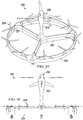
rotorcraft 10 includes apropulsion system 20 coupled tofuselage 12.Propulsion system 20 includes acentral fan assembly 22 and fourfan assemblies rotor disk 26 ofcentral fan assembly 22.Central fan assembly 22 andfan assemblies rotorcraft 10.Central fan assembly 22 includes amotor 28 that provides torque to fanblades 30.Fan assemblies motor fan blades Fan blades motors Fan assemblies mast 36 ofcentral fan assembly 22, although non-symmetric configurations are also within the scope of the illustrative embodiments. -
Fan blades 30 ofcentral fan assembly 22 have a larger rotational inertia, or moment of inertia or angular mass, thanfan blades fan assemblies fan blades 30 have a larger rotational inertia by virtue of being longer thanfan blades Fan blades 30 thus form alarger rotor disk 26, in terms of area and diameter, than each ofrotor disks fan blades fan blades fan blades 30,fan blades motors fan blades 30 in response to torque frommotor 28. On the other hand,fan blades 30 are capable of producing a larger maximum thrust than the maximum thrust produced by each set offan blades propulsion system 20 provides responsive control, handling and maneuverability forrotorcraft 10 usingfan assemblies central fan assembly 22.Central fan assembly 22 is capable of moving a higher air volume and/or may be more efficient in outputting thrust by virtue of having a higher inertia. However,fan assemblies inputs 40 from the pilot or from elsewhere, and be able to change speed rapidly for finer control ofrotorcraft 10. The smaller diameters offan assemblies fan blades fan assemblies Propulsion system 20 also provides a redundancy advantage by, for example, allowingfan assemblies central fan assembly 22 fails.Fan assemblies nimble rotorcraft 10, while higher inertiacentral fan assembly 22 helps to efficiently provide a high thrust for maximum payload carrying capacity. By utilizingfan assemblies central fan assembly 22 to achieve a higher maximum thrust,propulsion system 20 is able to utilize two or more fans, such as five fans in the illustrated embodiment, to achieve optimal responsiveness, maximum thrust and cost in managing the thrust ofrotorcraft 10. -
Motors rotorcraft 10 that provides rotational energy topropulsion system 20. Whilemotors other embodiments motors motors motors rotorcraft 10 may include an engine (not shown) that provides rotational energy tocentral fan assembly 22, andmotors fan assemblies central fan assembly 22 may rotate at a substantially fixed speed andfan blades 30 may be variable pitch fan blades whilefan assemblies fan blades Propulsion system 20 may utilize any number of motors or engines to drive the fan assemblies included therein. For example,propulsion system 20 may include a single motor or engine that drives allfan assemblies -
Fan assemblies fan assemblies fan blades 30 ofcentral fan assembly 22 may be large enough to allowfan blades 30 to autorotate in response to a high rate, underpowered or uncontrolled descent ofrotorcraft 10 while zero or little torque is provided bymotor 28.Rotorcraft 10 may thus retain the autorotation capabilities of traditional helicopters. In other embodiments,fan assemblies central fan assembly 22 may be a lower inertia fan assembly. In other embodiments,fan assembly 22 may not be centrally located relative tofan assemblies fan assemblies fan assemblies respective crane fuselage 12,fan assemblies fuselage 12 orcentral fan assembly 22 in any manner. In some embodiments,cranes fuselage 12 to allow for the movement offan assemblies fuselage 12. -
Rotorcraft 10 includes aflight control computer 44. In some embodiments,flight control computer 44 includes athrust controller 46 that controls the thrust ofrotorcraft 10 usingfan assemblies Thrust controller 46 may be in mechanical, electrical, wireless, computer or any other type ofcommunication 48 withfan assemblies Thrust controller 46 includes athrust determination module 50 to determine an amount by which to change or correct the thrust, including orientation, ofrotorcraft 10. In determining the thrust adjustment forrotorcraft 10, thrustdetermination module 50 may include and utilize any number or combination of the following sensors: a ram air sensor, downwash sensor, airspeed sensor, altitude sensor, attitude sensor, wind velocity sensor, cyclic control position sensor, collective control position sensor, roll rate sensor, yaw rate sensor, pitch rate sensor, acceleration sensor, such as a normal, lateral and/or longitudinal acceleration sensor, swashplate angle sensor, rotor flapping sensor, mechanical failure sensor, health monitoring system, descent rate sensor, traffic alert sensor or any other sensor suitable to perform the illustrative embodiments disclosed herein.Thrust controller 46 also includes afan control module 52 to modify the thrust ofrotorcraft 10 usingfan assemblies Fan control module 52 may determine the thrust magnitude of eachfan assembly rotorcraft 10 as determined bythrust determination module 50.Fan control module 52 may also determine how quickly thrust must be implemented so that the desired orientation or thrust is achieved in a timely manner.Fan control module 52 may thus determine whether and how fast to rotate eachfan assembly central fan assembly 22 has a higher rotational inertia, and thus a lower angular acceleration, thanfan assemblies determination module 50 may determine that a thrust is needed to quickly balance the roll ofrotorcraft 10, andfan control module 52 may activatefan assemblies rotorcraft 10. In another example, thrustdetermination module 50 may determine that a thrust is needed to level the pitch ofrotorcraft 10, andfan control module 52 may activatefan assemblies rotorcraft 10.Thrust controller 46 thus enhances the handling, maneuverability and controllability ofrotorcraft 10 by selectively activatingfan assemblies - It should be appreciated that
rotorcraft 10 is merely illustrative of a variety of aircraft that can implement the embodiments disclosed herein. Indeed,propulsion system 20 may be implemented on any aircraft with two or more fans or rotors. Other aircraft implementations can include hybrid aircraft, tiltrotor aircraft, tiltwing aircraft, quad tiltrotor aircraft, unmanned aircraft, gyrocopters, airplanes, helicopters and the like.Propulsion system 20 may also be utilized on any rotorcraft having a distributed propulsion system with two or more rotors powered by an electrical, hydraulic, mechanical or other energy source. As such, those skilled in the art will recognize thatpropulsion system 20 can be integrated into a variety of aircraft configurations. It should be appreciated that even though aircraft are particularly well-suited to implement the embodiments of the present disclosure, non-aircraft vehicles and devices can also implement the embodiments. - Referring to
figures 2A-2B in the drawings, various propulsion system configurations are shown by which to differentiate the rotational inertias of the fan assemblies therein. Referring tofigure 2A ,rotorcraft 100 includes highinertia fan assembly 102, which is centrally located between lowinertia fan assemblies inertia fan assemblies inertia fan assembly 102. Eachfan assembly motor fan blades inertia fan assembly 102 has a higher rotational inertia than lowinertia fan assemblies fan blades 110 andfan blades inertia fan assembly 102 includes a larger number offan blades 110. Highinertia fan assembly 102 includes eight fan blades and lowinertia fan assemblies inertia fan assembly 102 includes a larger number of fan blades,fan blades 110 collectively have a higher rotational inertia, have a lower angular acceleration and are capable of producing a higher maximum thrust thanfan blades inertia fan assembly inertia fan assembly 102 iscircumferential tip ring 114 coupled to the outboard tips offan blades 110 and rotatable with highinertia fan assembly 102.Circumferential tip ring 114 may help reduce tip and efficiency losses, increase thrust performance and reduce the noise produced by highinertia fan assembly 102.Circumferential tip ring 114 may also help to reduce the edgewise flow onfan blades 110 during flight, which can cause undesirable forces to act uponrotorcraft 100. Referring tofigure 2B ,rotorcraft 116 includes highinertia fan assembly 118, which is centrally located between lowinertia fan assemblies inertia fan assemblies inertia fan assembly 118. Eachfan assembly motor fan blades inertia fan assembly 118 has a higher rotational inertia than lowinertia fan assemblies fan blades inertia fan assembly 118 achieves a higher rotational inertia than lowinertia fan assemblies fan blades 126 being formed from a different material thanfan blades fan blades fan blades 126. In one non-limiting example,fan blades 126 may be formed from an aluminum or aluminum alloy material andfan blades fan blades 126 are formed. If cost is a compelling design constraint, composite, carbon-based or other expensive materials may be more sparingly used throughout the fan assemblies ofrotorcraft 116. In some embodiments,fan blades fan blades 126 may be formed from a high inertia and high strength material. - In some embodiments,
fan blades 126 of highinertia fan assembly 118 may include tip weights to increase the rotational inertia offan blades 126, which may also assist highinertia fan assembly 118 in performing an autorotation maneuver. The rotational inertias offan assemblies fan blades blades 126. For example,width 130 offan blades width 132 offan blades 126. The rotational inertias offan assemblies fan blades blades 126. The widths and surface areas offan blades blades - Referring to
figures 3A-3F in the drawings, various propulsion system configurations for a rotorcraft are schematically illustrated. Referring tofigures 3A-3B ,rotorcraft 200 includes four lowinertia fan assemblies inertia fan assembly 204 each having respective fan blades rotated by a respective motor. Lowinertia fan assemblies mast 206 of highinertia fan assembly 204. Highinertia fan assembly 204 has a higher rotational inertia than lowinertia fan assemblies inertia fan assemblies rotor disk 208 of highinertia fan assembly 204. Therefore, lowinertia fan assemblies inertia fan assembly 204. While lowinertia fan assemblies rotor disk 208, lowinertia fan assemblies rotor disk 208. Lowinertia fan assemblies distance 210 beneath highinertia fan assembly 204. In other embodiments, the distances between highinertia fan assembly 204 and each lowinertia fan assembly - Referring to
figure 3C ,rotorcraft 214 includes six lowinertia fan assemblies inertia fan assembly 218 each having respective fan blades rotated by a respective motor. Lowinertia fan assemblies longitudinal axis 220 ofrotorcraft 214. Highinertia fan assembly 218 has a higher rotational inertia than lowinertia fan assemblies Rotorcraft 214 may have any ratio of low inertia fan assemblies to high inertia fan assemblies, such as 2:1, 3:1, 4:1, 4:2, 6:1, 3:2, 9:1, 1:2, 1:3, 1:4, 2:4, 1:6, 2:3, 9:1 or any other ratio.Cranes inertia fan assembly crane - Referring to
figure 3D ,rotorcraft 226 includeswings fuselage 232. Highinertia fan assemblies wings inertia fan assemblies Shrouds inertia fan assemblies shroud 236a of highinertia fan assembly 234a byconnection members inertia fan assemblies inertia fan assembly 234a depending on the embodiment.Shrouds inertia fan assemblies shroud 236b of highinertia fan assembly 234b byconnection members inertia fan assemblies inertia fan assembly 234b depending on the embodiment.Fan assemblies Fan assemblies longitudinal axis 244 ofrotorcraft 226. Highinertia fan assemblies inertia fan assemblies inertia fan assemblies fuselage 232 abouttilt axis 246, thus allowingfan assemblies rotorcraft 226 may be a tiltrotor aircraft in whichfan assemblies fan assemblies fan assemblies rotorcraft 226 may include any ratio of open fan assemblies to shrouded fan assemblies. For example, lowinertia fan assemblies inertia fan assemblies shrouds inertia fan assemblies fuselage 232 or another portion ofrotorcraft 226. - Referring to
figures 3E-3F ,unmanned rotorcraft 250 includesfuselage 252 surrounded by aclosed wing 254. Highinertia fan assembly 256 is rotatably coupled tofuselage 252 and lowinertia fan assemblies 258 are rotatably coupled toclosed wing 254.Closed wing 254 is coupled tofuselage 252 byspokes 260.Fan assemblies inertia fan assembly 256 has a higher rotational inertia than lowinertia fan assembly 258. While nine lowinertia fan assemblies 258 and a single highinertia fan assembly 256 are shown in the illustrated embodiment,rotorcraft 250 may include any number of low or high inertia fan assemblies depending on the requirements and desired attributes of the rotorcraft. In some embodiments, highinertia fan assembly 256 may include variable pitch fan blades. Also, any number offan assemblies spokes 260 may also include fan assemblies rotatably coupled thereto. - The flight control computers of the present embodiments preferably include computing elements such as non-transitory computer readable storage media that include computer instructions executable by processors for controlling flight operations. The computing elements may be implemented as one or more general-purpose computers, special purpose computers or other machines with memory and processing capability. The computing elements may include one or more memory storage modules including, but is not limited to, internal storage memory such as random access memory, non-volatile memory such as read only memory, removable memory such as magnetic storage memory, optical storage, solid-state storage memory or other suitable memory storage entity. The computing elements may be implemented as microprocessor-based systems operable to execute program code in the form of machine-executable instructions. The computing elements may be selectively connectable to other computer systems via a proprietary encrypted network, a public encrypted network, the Internet or other suitable communication network that may include both wired and wireless connections.
- The foregoing description of embodiments of the disclosure has been presented for purposes of illustration and description. It is not intended to be exhaustive or to limit the disclosure to the precise form disclosed, and modifications and variations are possible in light of the above teachings or may be acquired from practice of the disclosure. The embodiments were chosen and described in order to explain the principals of the disclosure and its practical application to enable one skilled in the art to utilize the disclosure in various embodiments and with various modifications as are suited to the particular use contemplated. Other substitutions, modifications, changes and omissions may be made in the design, operating conditions and arrangement of the embodiments without departing from the scope of the present disclosure. Such modifications and combinations of the illustrative embodiments as well as other embodiments will be apparent to persons skilled in the art upon reference to the description. It is, therefore, intended that the appended claims encompass any such modifications or embodiments.
Claims (16)
- A propulsion system for a rotorcraft comprising:a first fan assembly including a plurality of first fan blades;a second fan assembly including a plurality of second fan blades; anda drive system adapted to provide torque to the first and second fan blades;wherein, the first fan blades have a larger rotational inertia than the second fan blades; and
wherein, the second fan blades are adapted to experience a larger angular acceleration than the first fan blades in response to torque from the drive system, thereby providing responsive thrust control for the rotorcraft. - The propulsion system as recited in claim 1 wherein the first and second fan blades further comprise fixed pitch fan blades.
- The propulsion system as recited in claim 1 or in claim 2 wherein the first fan blades are longer than the second fan blades.
- The propulsion system as recited in claim 1 or in claim 2 or in claim 3 wherein the first fan blades are formed from a different material than the second fan blades.
- The propulsion system as recited in claim 1 or in any preceding claim wherein the plurality of first fan blades include a larger number of fan blades than the plurality of second fan blades.
- The propulsion system as recited in claim 1 or in any preceding claim wherein the first fan blades are wider than the second fan blades.
- The propulsion system as recited in claim 1 or in any preceding claim wherein the first fan blades further comprise a circumferential tip ring.
- The propulsion system as recited in claim 1 or in any preceding claim wherein:-(i) at least one of the first or second fan assemblies further comprise a shrouded fan assembly; or(ii) at least one of the first or second fan assemblies further comprise an open fan assembly.
- The propulsion system as recited in claim 1 or in any preceding claim wherein the first fan blades are adapted to provide a larger maximum thrust than the second fan blades.
- The propulsion system as recited in claim 1 or in any preceding claim wherein:-(i) the drive system further comprises an electric motor; and/or(ii) wherein the drive system further comprises a hydraulic motor.
- The propulsion system as recited in claim 1 or in any preceding claim wherein the drive system further comprises a variable speed motor.
- A rotorcraft comprising:a fuselage; anda propulsion system coupled to the fuselage, the propulsion system comprising:a first fan assembly including a plurality of first fan blades;a second fan assembly including a plurality of second fan blades; anda drive system adapted to provide torque to the first and second fan blades;wherein, the first fan blades have a larger rotational inertia than the second fan blades; and
wherein, the second fan blades are adapted to experience a larger angular acceleration than the first fan blades in response to torque from the drive system, thereby providing responsive thrust control for the rotorcraft. - The rotorcraft as recited in claim 12 wherein the second fan assembly further comprises a plurality of second fan assemblies; and optionally or preferably wherein the plurality of second fan assemblies further comprise at least four second fan assemblies.
- The rotorcraft as recited in claim 13 wherein the first fan assembly further comprises a central fan assembly including a mast; and
wherein the second fan assemblies are radially symmetric about the mast of the central fan assembly. - The rotorcraft as recited in claim 14 wherein:-(i) the central fan assembly forms a rotor disk and the second fan assemblies are disposed outboard of the rotor disk of the central fan assembly; or(ii) the central fan assembly forms a rotor disk and the second fan assemblies are disposed underneath the rotor disk of the central fan assembly.
- The rotorcraft as recited in claim 14 or in claim 15 wherein the first fan blades of the central fan assembly further comprise variable pitch fan blades; and
wherein the second fan blades of the second fan assemblies further comprise fixed pitch fan blades.
Applications Claiming Priority (1)
| Application Number | Priority Date | Filing Date | Title |
|---|---|---|---|
| US15/909,246 US20190270516A1 (en) | 2018-03-01 | 2018-03-01 | Propulsion Systems for Rotorcraft |
Publications (2)
| Publication Number | Publication Date |
|---|---|
| EP3533708A1 true EP3533708A1 (en) | 2019-09-04 |
| EP3533708B1 EP3533708B1 (en) | 2020-09-23 |
Family
ID=64949115
Family Applications (1)
| Application Number | Title | Priority Date | Filing Date |
|---|---|---|---|
| EP18216007.7A Active EP3533708B1 (en) | 2018-03-01 | 2018-12-31 | Rotorcraft and propulsion systems for rotorcraft |
Country Status (3)
| Country | Link |
|---|---|
| US (2) | US20190270516A1 (en) |
| EP (1) | EP3533708B1 (en) |
| CN (1) | CN110217384B (en) |
Cited By (1)
| Publication number | Priority date | Publication date | Assignee | Title |
|---|---|---|---|---|
| US20190270516A1 (en) * | 2018-03-01 | 2019-09-05 | Bell Helicopter Textron Inc. | Propulsion Systems for Rotorcraft |
Families Citing this family (16)
| Publication number | Priority date | Publication date | Assignee | Title |
|---|---|---|---|---|
| DE102018133171B4 (en) * | 2018-12-20 | 2026-07-16 | Volocopter Technologies Gmbh | aircraft |
| NL1043177B1 (en) * | 2019-03-04 | 2020-09-17 | Pal V Ip B V | Vertical Take Off and Landing Vehicle |
| CN116867102A (en) * | 2019-09-30 | 2023-10-10 | 华为技术有限公司 | Data transmission method and device |
| US11565803B2 (en) | 2020-03-04 | 2023-01-31 | Textron Innovations Inc. | Electric drive system line replaceable unit with integrated cyclic actuation |
| US11472544B2 (en) | 2020-03-04 | 2022-10-18 | Textron Innovations Inc. | Electric drive system line replaceable unit with integrated collective actuation |
| US11554859B2 (en) | 2020-03-04 | 2023-01-17 | Textron Innovations Inc. | Electric drive system line replaceable unit with integrated thermal cooling |
| US11831220B2 (en) | 2020-06-22 | 2023-11-28 | Textron Innovations Inc. | Electric motor stack with integral one-piece gearbox input shaft |
| US11390395B2 (en) | 2020-06-25 | 2022-07-19 | Textron Innovations Inc. | Aircraft rotor assembly with segmented input shaft for electric motor stack and gearbox unit |
| US11814163B2 (en) | 2021-01-13 | 2023-11-14 | Textron Innovations Inc. | Electric tiltrotor aircraft with tilting coaxial motors and gearbox |
| US11760473B2 (en) | 2021-02-11 | 2023-09-19 | Karem Aircraft, Inc. | Rotorcraft with interchangeable rotor diameters |
| US20220412302A1 (en) * | 2021-05-04 | 2022-12-29 | Bogdan Tudor Bucheru | Systems and methods for interleaved synchronous propeller system |
| US12024285B1 (en) | 2022-03-10 | 2024-07-02 | Skypad Tech, Inc. | Modular mobility system including thrusters movably connected to a support structure |
| JPWO2023188269A1 (en) * | 2022-03-31 | 2023-10-05 | ||
| WO2024067896A1 (en) * | 2022-09-28 | 2024-04-04 | Ramin Assisi | Aircraft and method for operating an aircraft |
| US12397909B2 (en) * | 2023-01-06 | 2025-08-26 | Mihai Pruna, JR. | Supplementary lift generation system for multicopter rotorcraft |
| CN121894197A (en) * | 2026-03-26 | 2026-04-21 | 北京航空航天大学 | Heterogeneous vertical lifting layout of coaxial main rotor wing-tilting multi-slave rotor wing |
Citations (6)
| Publication number | Priority date | Publication date | Assignee | Title |
|---|---|---|---|---|
| DE102005046155A1 (en) * | 2005-09-27 | 2007-04-12 | Emt Ingenieurgesellschaft Dipl.-Ing. Hartmut Euer Mbh | Helicopter with coaxial, contrarotating main rotors has at least three control drives at distance from main rotor axle; each control drive has rotor and drive device |
| EP2394914A1 (en) * | 2010-06-12 | 2011-12-14 | Promark Sp. z o.o. | A rotorcraft with a coaxial rotor system |
| US20130206915A1 (en) * | 2010-04-22 | 2013-08-15 | Jean-Marc (Joseph) Desaulniers | Vertical take-off and landing multimodal, multienvironment, gyropendular craft with compensatory propulsion and fluidic gradient collimation |
| US20130205941A1 (en) * | 2010-10-18 | 2013-08-15 | Yuji Tanose | Horizontal attitude stabilization device for disc air vehicle |
| WO2015061857A1 (en) * | 2013-11-01 | 2015-05-07 | The University Of Queensland | A rotorcraft |
| EP3254962A1 (en) * | 2016-06-03 | 2017-12-13 | Bell Helicopter Textron Inc. | Electric distributed propulsion anti-torque redundant power and control system |
Family Cites Families (93)
| Publication number | Priority date | Publication date | Assignee | Title |
|---|---|---|---|---|
| US2318260A (en) * | 1940-04-09 | 1943-05-04 | United Aircraft Corp | Helicopter and controls therefor |
| US2330204A (en) * | 1941-09-15 | 1943-09-28 | Autogiro Co Of America | Multirotor aircraft |
| US2672939A (en) * | 1946-07-30 | 1954-03-23 | Autogiro Co Of America | Rotor-equipped aircraft |
| US2670804A (en) * | 1946-11-22 | 1954-03-02 | Autogiro Co Of America | Aircraft having rotative sustaining blades and control mechanism for such aircraft |
| US2514822A (en) * | 1949-08-19 | 1950-07-11 | Jr Frank H Wolfe | Helicopter automobile |
| US3185410A (en) * | 1963-10-21 | 1965-05-25 | Raymond C Smart | Vertical lift aircraft |
| US3345016A (en) * | 1965-08-17 | 1967-10-03 | Eickmann Karl | Fluidborne vehicle, driven by hydraulic motors and partially controlled by variable bypass means |
| US3801046A (en) * | 1966-05-24 | 1974-04-02 | K Eickmann | Fluid borne craft driven by hydrostatically operated propellers governed by an accident peventing automatic control device |
| US3632065A (en) * | 1969-11-19 | 1972-01-04 | Vlm Corp The | Rotary wing aircraft |
| US3614029A (en) * | 1970-06-12 | 1971-10-19 | Karl Eickmann | Added fluidflow control means for governing the attitude of fluidborne vehicles |
| US3986686A (en) * | 1975-06-02 | 1976-10-19 | Teledyne Ryan Aeronautical A Division Of Teledyne Industries, Inc. | Aircraft with retractable rotor wing |
| US4768737A (en) * | 1987-03-02 | 1988-09-06 | Pbsystems, Inc. | Helicopter control system |
| US4765567A (en) * | 1987-03-10 | 1988-08-23 | Tech Serv, Inc. | Helicopter target |
| US4856732A (en) * | 1987-05-01 | 1989-08-15 | Karl Eickmann | Airborne vehicle with hydraulic drive and control |
| GB2243132A (en) * | 1989-09-11 | 1991-10-23 | Peter A Hulmes | Helicopters with twin rotors |
| JPH07156890A (en) | 1993-12-02 | 1995-06-20 | Mitsubishi Heavy Ind Ltd | Helicopter |
| US5879131A (en) * | 1994-04-25 | 1999-03-09 | Arlton; Paul E. | Main rotor system for model helicopters |
| JPH09175495A (en) | 1995-12-21 | 1997-07-08 | Fujita Corp | Helicopter tail rotor |
| US5746390A (en) * | 1996-03-20 | 1998-05-05 | Fran Rich Chi Associates, Inc. | Air-land vehicle with ducted fan vanes providing improved performance |
| FR2769586B1 (en) * | 1997-10-01 | 1999-11-19 | Pierre Hardoin | HYDROPAL - AIR TERRESTRIAL HP 02 |
| US7497759B1 (en) * | 2001-03-28 | 2009-03-03 | Steven Davis | Directionally controllable, self-stabilizing, rotating flying vehicle |
| NO317612B1 (en) * | 2003-05-20 | 2004-11-22 | Proxflyer As | Rotor generating attic and use of rotor |
| US7857253B2 (en) * | 2003-10-27 | 2010-12-28 | Urban Aeronautics Ltd. | Ducted fan VTOL vehicles |
| US7802755B2 (en) * | 2004-03-10 | 2010-09-28 | Poltorak Alexander I | Rotating wing aircraft with tip-driven rotor and rotor guide-ring |
| US9434471B2 (en) * | 2005-04-14 | 2016-09-06 | Paul E Arlton | Rotary wing vehicle |
| US7946526B2 (en) * | 2004-11-05 | 2011-05-24 | Nachman Zimet | Rotary-wing vehicle system |
| US7032860B1 (en) | 2004-11-05 | 2006-04-25 | Eatts, Llc | Emergency anti-torque thruster system |
| US7699260B2 (en) * | 2005-01-14 | 2010-04-20 | Hughey Electricopter Corporation | Vertical takeoff and landing aircraft using a redundant array of independent rotors |
| US20070095973A1 (en) * | 2005-10-27 | 2007-05-03 | Douglas Challis | Aircraft having a helicopter rotor and an inclined front mounted propeller |
| GB2432348B (en) * | 2005-11-16 | 2008-04-23 | Peter Gregory Lloyd | Emergency device |
| ITNA20060002A1 (en) * | 2006-01-13 | 2007-07-14 | Vladimiro Lidak | TAIL ROTOR FOR HELICOPTERS WITH VELOCITY CHANGE WITH HYDROSTATIC DRIVE. |
| EP2121439B1 (en) * | 2007-02-16 | 2012-11-14 | Donald Orval Shaw | Modular flying vehicle |
| JP2009051465A (en) | 2007-08-29 | 2009-03-12 | Mitsubishi Heavy Ind Ltd | Tail rotor device and helicopter |
| JP2009090755A (en) | 2007-10-05 | 2009-04-30 | Mitsubishi Heavy Ind Ltd | Tail rotor |
| GB2462452B (en) * | 2008-08-08 | 2011-02-02 | Univ Manchester | A rotary wing vehicle |
| US9889928B2 (en) * | 2009-08-26 | 2018-02-13 | Manuel Salz | Lift, propulsion and stabilising system for vertical take-off and landing aircraft |
| US8196855B2 (en) | 2009-11-23 | 2012-06-12 | Balkus Jr Carl E | Helicopter auxiliary anti-torque system |
| FR2959205B1 (en) * | 2010-04-27 | 2012-04-13 | Eurocopter France | METHOD FOR CONTROLLING AND REGULATING THE TURNING ANGLE OF A HYBRID HELICOPTER VEHICLE |
| SE535346C2 (en) * | 2010-06-08 | 2012-07-03 | Jan-Evert Lindmark | survival craft |
| US20180072408A9 (en) * | 2010-10-21 | 2018-03-15 | Charles Howard Medlock | Torque balanced, lift rotor module providing increased lift with few or no moving parts |
| US8695919B2 (en) * | 2010-11-12 | 2014-04-15 | Sky Sapience Ltd. | Aerial unit and method for elevating payloads |
| KR101340409B1 (en) * | 2012-02-15 | 2013-12-13 | 주식회사 한울로보틱스 | Hybrid Unmanned Aerial Vehicle |
| WO2013124300A1 (en) * | 2012-02-22 | 2013-08-29 | E-Volo Gmbh | Aircraft |
| US9004973B2 (en) * | 2012-10-05 | 2015-04-14 | Qfo Labs, Inc. | Remote-control flying copter and method |
| WO2014198641A1 (en) * | 2013-06-09 | 2014-12-18 | Eth Zurich | Volitant vehicle rotating about an axis and method for controlling the same |
| US9815553B2 (en) | 2013-07-01 | 2017-11-14 | Bell Helicopter Tectron Inc. | Independent hydraulic control system for rotorcraft secondary rotor |
| KR101575120B1 (en) * | 2013-11-06 | 2015-12-07 | 이희성 | Flying Apparatus Having Multiple Rotors |
| IL231811A (en) * | 2014-03-30 | 2017-08-31 | Yefim Kereth | Asymmetric multirotor helicopter |
| WO2016081041A1 (en) * | 2014-08-29 | 2016-05-26 | Reference Technologies Inc. | Muiti-propulsion design for unmanned aerial systems |
| JP6425968B2 (en) * | 2014-10-29 | 2018-11-21 | ヤンマー株式会社 | helicopter |
| US9919797B2 (en) * | 2014-12-04 | 2018-03-20 | Elwha Llc | System and method for operation and management of reconfigurable unmanned aircraft |
| KR101579409B1 (en) * | 2014-12-26 | 2015-12-23 | 남승호 | Talk of vertical takeoff and landing aircraft-type propeller removal and balancing device Combination |
| FR3032687B1 (en) * | 2015-02-16 | 2018-10-12 | Hutchinson | AERODYNE VTOL WITH SOUFFLANTE (S) AXIALE (S) CARRIER (S) |
| US20160236775A1 (en) * | 2015-02-18 | 2016-08-18 | Siniger LLC | Vertical takeoff and landing aircraft |
| WO2016164280A1 (en) * | 2015-04-04 | 2016-10-13 | Skylift Global | Multi-rotor vehicle with yaw control and autorotation |
| US20160325834A1 (en) * | 2015-05-07 | 2016-11-10 | Curtis Asa Foster | In-flight battery recharging system for an unmanned aerial vehicle |
| GB201509509D0 (en) * | 2015-06-01 | 2015-07-15 | Imp Innovations Ltd | Aerial devices capable of controlled flight |
| WO2017002054A1 (en) * | 2015-06-30 | 2017-01-05 | Afghan Ismail Khan | A rotor arrangement with offset hubs for the air crafts |
| CN104973241A (en) * | 2015-07-08 | 2015-10-14 | 芜湖万户航空航天科技有限公司 | Unmanned aerial vehicle with main and auxiliary multi-rotor structure |
| FR3038882B1 (en) * | 2015-07-16 | 2018-03-23 | Airbus Helicopters | COMBINED AIRCRAFT PROVIDED WITH AN ADDITIONAL ANTICOUPLE DEVICE |
| FR3039506B1 (en) * | 2015-07-31 | 2019-05-24 | Innostar | SUSTENTATION ROTOR AND HYBRID AERODYNE WITH VERTICAL OR SHORT TAKEOFF AND / OR LANDING COMPRISING THE SAME |
| CN205229808U (en) * | 2015-12-25 | 2016-05-11 | 西北工业大学 | Integration of many power flies accuse system for little small aircraft |
| US10343770B2 (en) * | 2016-03-01 | 2019-07-09 | Joe H. Mullins | Torque and pitch managed quad-rotor aircraft |
| WO2017153807A1 (en) * | 2016-03-10 | 2017-09-14 | Yoav Netzer | Convertible rotor aircraft |
| US10703471B2 (en) | 2016-06-03 | 2020-07-07 | Bell Helicopter Textron Inc. | Anti-torque control using matrix of fixed blade pitch motor modules |
| US10377479B2 (en) | 2016-06-03 | 2019-08-13 | Bell Helicopter Textron Inc. | Variable directional thrust for helicopter tail anti-torque system |
| US10106253B2 (en) * | 2016-08-31 | 2018-10-23 | Bell Helicopter Textron Inc. | Tilting ducted fan aircraft generating a pitch control moment |
| WO2018076047A1 (en) * | 2016-10-24 | 2018-05-03 | Hybridskys Technology Pty Ltd | Hybrid aircraft |
| US11673676B2 (en) * | 2017-02-23 | 2023-06-13 | William J. Neff | Hybrid VTOL aerial vehicle |
| JP2020511350A (en) * | 2017-03-10 | 2020-04-16 | トップ フライト テクノロジーズ, インコーポレイテッド | Power system cooling for unmanned aerial vehicles |
| GB2566095B (en) * | 2017-09-04 | 2019-10-02 | Artemis Intelligent Power Ltd | Hydraulic multi-rotor aerial vehicle |
| US10994835B2 (en) * | 2017-09-28 | 2021-05-04 | Textron Innovations Inc. | Inertia weight assemblies for rotorcraft |
| US10796275B1 (en) * | 2017-10-27 | 2020-10-06 | Amazon Technologies, Inc. | Systems and methods for inventory control and delivery using unmanned aerial vehicles |
| EP3501983B2 (en) | 2017-12-22 | 2025-08-20 | LEONARDO S.p.A. | Anti-torque system for a helicopter and method for controlling an anti-torque system for a helicopter |
| RU181389U1 (en) * | 2018-01-09 | 2018-07-11 | Федеральное государственное бюджетное образовательное учреждение высшего образования "Казанский национальный исследовательский технический университет им. А.Н. Туполева-КАИ" (КНИТУ-КАИ) | MODULAR DESIGN OF THE UNMANNED AIRCRAFT VERTICAL TAKEOFF AND LANDING WITH COMBINED POWER PLANT |
| CN207791151U (en) * | 2018-01-23 | 2018-08-31 | 王锦锐 | A kind of novel hybrid complex controll aircraft |
| US20190270516A1 (en) * | 2018-03-01 | 2019-09-05 | Bell Helicopter Textron Inc. | Propulsion Systems for Rotorcraft |
| US11174016B2 (en) * | 2018-05-03 | 2021-11-16 | Jaunt Air Mobility, Llc | Compound rotorcraft with propeller |
| US10906637B2 (en) * | 2018-05-17 | 2021-02-02 | Textron Innovations Inc. | Assisted landing systems for rotorcraft |
| JP6461451B1 (en) * | 2018-08-03 | 2019-01-30 | 楽天株式会社 | Aircraft protection member |
| US20200108919A1 (en) * | 2018-10-17 | 2020-04-09 | Jaime Guillermo Sada | Quiet Redundant Rotorcraft |
| US11999474B2 (en) * | 2018-11-05 | 2024-06-04 | Yoav Netzer | Aircraft rotor protection |
| JP2022107078A (en) * | 2019-02-08 | 2022-07-21 | 株式会社ナイルワークス | Drone system |
| CN109625259A (en) * | 2019-02-25 | 2019-04-16 | 江富余 | Cross-arranging type propeller aircraft helicopter |
| US11673657B2 (en) * | 2019-05-03 | 2023-06-13 | The Boeing Company | Multi-rotor rotorcraft |
| CN110254704A (en) * | 2019-07-24 | 2019-09-20 | 江富余 | Division of labor formula propeller aircraft helicopter |
| JPWO2021166140A1 (en) * | 2020-02-20 | 2021-08-26 | ||
| US11572160B1 (en) * | 2020-03-20 | 2023-02-07 | Snap Inc. | Unmanned aerial vehicle with object detection propeller stoppage |
| US12304616B2 (en) * | 2020-05-26 | 2025-05-20 | Kaunas University Of Technology | Aircraft thrust control system |
| CN113905946A (en) * | 2020-06-29 | 2022-01-07 | 深圳市大疆创新科技有限公司 | Unmanned aerial vehicle and be applicable to unmanned aerial vehicle's protector |
| JP6997929B1 (en) * | 2020-08-07 | 2022-01-18 | 楽天グループ株式会社 | Flying object |
| US12093060B2 (en) * | 2021-01-29 | 2024-09-17 | Digital Aerolus, Inc. | Geometric control envelope system and method for limiting commands to actuator mapping function |
| US11987402B2 (en) * | 2021-03-29 | 2024-05-21 | The Boeing Company | Vertical air vehicle takeoff and landing stabilization apparatuses, systems, and methods |
-
2018
- 2018-03-01 US US15/909,246 patent/US20190270516A1/en not_active Abandoned
- 2018-12-31 EP EP18216007.7A patent/EP3533708B1/en active Active
-
2019
- 2019-03-01 CN CN201910154777.6A patent/CN110217384B/en active Active
-
2020
- 2020-10-21 US US17/076,399 patent/US11718390B2/en active Active
Patent Citations (6)
| Publication number | Priority date | Publication date | Assignee | Title |
|---|---|---|---|---|
| DE102005046155A1 (en) * | 2005-09-27 | 2007-04-12 | Emt Ingenieurgesellschaft Dipl.-Ing. Hartmut Euer Mbh | Helicopter with coaxial, contrarotating main rotors has at least three control drives at distance from main rotor axle; each control drive has rotor and drive device |
| US20130206915A1 (en) * | 2010-04-22 | 2013-08-15 | Jean-Marc (Joseph) Desaulniers | Vertical take-off and landing multimodal, multienvironment, gyropendular craft with compensatory propulsion and fluidic gradient collimation |
| EP2394914A1 (en) * | 2010-06-12 | 2011-12-14 | Promark Sp. z o.o. | A rotorcraft with a coaxial rotor system |
| US20130205941A1 (en) * | 2010-10-18 | 2013-08-15 | Yuji Tanose | Horizontal attitude stabilization device for disc air vehicle |
| WO2015061857A1 (en) * | 2013-11-01 | 2015-05-07 | The University Of Queensland | A rotorcraft |
| EP3254962A1 (en) * | 2016-06-03 | 2017-12-13 | Bell Helicopter Textron Inc. | Electric distributed propulsion anti-torque redundant power and control system |
Cited By (1)
| Publication number | Priority date | Publication date | Assignee | Title |
|---|---|---|---|---|
| US20190270516A1 (en) * | 2018-03-01 | 2019-09-05 | Bell Helicopter Textron Inc. | Propulsion Systems for Rotorcraft |
Also Published As
| Publication number | Publication date |
|---|---|
| EP3533708B1 (en) | 2020-09-23 |
| US20190270516A1 (en) | 2019-09-05 |
| US11718390B2 (en) | 2023-08-08 |
| US20210031908A1 (en) | 2021-02-04 |
| CN110217384A (en) | 2019-09-10 |
| CN110217384B (en) | 2023-04-07 |
Similar Documents
| Publication | Publication Date | Title |
|---|---|---|
| EP3533708B1 (en) | Rotorcraft and propulsion systems for rotorcraft | |
| EP3483065B1 (en) | Multirotor aircraft with collective for autorotation | |
| EP3527492B1 (en) | Anti-torque systems for rotorcraft | |
| EP3486168B1 (en) | Extended range tiltrotor aircraft | |
| US11603193B2 (en) | Aircraft convertible between fixed-wing and hovering orientations | |
| US11332240B2 (en) | Anti-torque systems for rotorcraft | |
| US10144509B2 (en) | High performance VTOL aircraft | |
| US10414492B2 (en) | Aircraft having rotor-to-wing conversion capabilities | |
| US10407169B2 (en) | Aircraft having dual rotor-to-wing conversion capabilities | |
| US10946956B2 (en) | Unmanned aerial systems having out of phase gimballing axes | |
| EP3684686B1 (en) | Unmanned aerial vehicle with co-axial reversible rotors | |
| US20130105635A1 (en) | Quad tilt rotor vertical take off and landing (vtol) unmanned aerial vehicle (uav) with 45 degree rotors | |
| EP2394914A1 (en) | A rotorcraft with a coaxial rotor system | |
| US10293931B2 (en) | Aircraft generating a triaxial dynamic thrust matrix | |
| KR101755278B1 (en) | Vertical takeoff and landing unmanned aerial vehicle having fixed wing, equipped with hybrid propeller system | |
| WO2016028358A2 (en) | High Performance VTOL Aircraft | |
| JPWO2016136848A1 (en) | Multicopter | |
| WO2008085192A2 (en) | Rotorcraft with opposing roll mast moments, and related methods | |
| CN107089322A (en) | One kind becomes the dynamic multi-rotor unmanned aerial vehicle of lift structure oil | |
| US12084175B2 (en) | Variable incidence wing aircraft having a wing stowage mode | |
| JP2024536455A (en) | Method for obtaining lift and thrust for horizontal flight while maintaining horizontal stability of a vertical take-off and landing aircraft, and an aircraft implementing this method | |
| CN105438464A (en) | Aircraft and control method thereof |
Legal Events
| Date | Code | Title | Description |
|---|---|---|---|
| STAA | Information on the status of an ep patent application or granted ep patent |
Free format text: STATUS: EXAMINATION IS IN PROGRESS |
|
| PUAI | Public reference made under article 153(3) epc to a published international application that has entered the european phase |
Free format text: ORIGINAL CODE: 0009012 |
|
| 17P | Request for examination filed |
Effective date: 20181231 |
|
| AK | Designated contracting states |
Kind code of ref document: A1 Designated state(s): AL AT BE BG CH CY CZ DE DK EE ES FI FR GB GR HR HU IE IS IT LI LT LU LV MC MK MT NL NO PL PT RO RS SE SI SK SM TR |
|
| AX | Request for extension of the european patent |
Extension state: BA ME |
|
| GRAP | Despatch of communication of intention to grant a patent |
Free format text: ORIGINAL CODE: EPIDOSNIGR1 |
|
| STAA | Information on the status of an ep patent application or granted ep patent |
Free format text: STATUS: GRANT OF PATENT IS INTENDED |
|
| INTG | Intention to grant announced |
Effective date: 20200713 |
|
| GRAS | Grant fee paid |
Free format text: ORIGINAL CODE: EPIDOSNIGR3 |
|
| GRAA | (expected) grant |
Free format text: ORIGINAL CODE: 0009210 |
|
| STAA | Information on the status of an ep patent application or granted ep patent |
Free format text: STATUS: THE PATENT HAS BEEN GRANTED |
|
| RAP1 | Party data changed (applicant data changed or rights of an application transferred) |
Owner name: TEXTRON INNOVATIONS INC. |
|
| AK | Designated contracting states |
Kind code of ref document: B1 Designated state(s): AL AT BE BG CH CY CZ DE DK EE ES FI FR GB GR HR HU IE IS IT LI LT LU LV MC MK MT NL NO PL PT RO RS SE SI SK SM TR |
|
| REG | Reference to a national code |
Ref country code: GB Ref legal event code: FG4D |
|
| REG | Reference to a national code |
Ref country code: CH Ref legal event code: EP |
|
| REG | Reference to a national code |
Ref country code: IE Ref legal event code: FG4D |
|
| REG | Reference to a national code |
Ref country code: AT Ref legal event code: REF Ref document number: 1316146 Country of ref document: AT Kind code of ref document: T Effective date: 20201015 Ref country code: DE Ref legal event code: R096 Ref document number: 602018008107 Country of ref document: DE |
|
| PG25 | Lapsed in a contracting state [announced via postgrant information from national office to epo] |
Ref country code: GR Free format text: LAPSE BECAUSE OF FAILURE TO SUBMIT A TRANSLATION OF THE DESCRIPTION OR TO PAY THE FEE WITHIN THE PRESCRIBED TIME-LIMIT Effective date: 20201224 Ref country code: BG Free format text: LAPSE BECAUSE OF FAILURE TO SUBMIT A TRANSLATION OF THE DESCRIPTION OR TO PAY THE FEE WITHIN THE PRESCRIBED TIME-LIMIT Effective date: 20201223 Ref country code: NO Free format text: LAPSE BECAUSE OF FAILURE TO SUBMIT A TRANSLATION OF THE DESCRIPTION OR TO PAY THE FEE WITHIN THE PRESCRIBED TIME-LIMIT Effective date: 20201223 Ref country code: SE Free format text: LAPSE BECAUSE OF FAILURE TO SUBMIT A TRANSLATION OF THE DESCRIPTION OR TO PAY THE FEE WITHIN THE PRESCRIBED TIME-LIMIT Effective date: 20200923 Ref country code: HR Free format text: LAPSE BECAUSE OF FAILURE TO SUBMIT A TRANSLATION OF THE DESCRIPTION OR TO PAY THE FEE WITHIN THE PRESCRIBED TIME-LIMIT Effective date: 20200923 Ref country code: FI Free format text: LAPSE BECAUSE OF FAILURE TO SUBMIT A TRANSLATION OF THE DESCRIPTION OR TO PAY THE FEE WITHIN THE PRESCRIBED TIME-LIMIT Effective date: 20200923 |
|
| REG | Reference to a national code |
Ref country code: AT Ref legal event code: MK05 Ref document number: 1316146 Country of ref document: AT Kind code of ref document: T Effective date: 20200923 |
|
| PG25 | Lapsed in a contracting state [announced via postgrant information from national office to epo] |
Ref country code: LV Free format text: LAPSE BECAUSE OF FAILURE TO SUBMIT A TRANSLATION OF THE DESCRIPTION OR TO PAY THE FEE WITHIN THE PRESCRIBED TIME-LIMIT Effective date: 20200923 Ref country code: RS Free format text: LAPSE BECAUSE OF FAILURE TO SUBMIT A TRANSLATION OF THE DESCRIPTION OR TO PAY THE FEE WITHIN THE PRESCRIBED TIME-LIMIT Effective date: 20200923 |
|
| REG | Reference to a national code |
Ref country code: NL Ref legal event code: MP Effective date: 20200923 |
|
| REG | Reference to a national code |
Ref country code: LT Ref legal event code: MG4D |
|
| PG25 | Lapsed in a contracting state [announced via postgrant information from national office to epo] |
Ref country code: LT Free format text: LAPSE BECAUSE OF FAILURE TO SUBMIT A TRANSLATION OF THE DESCRIPTION OR TO PAY THE FEE WITHIN THE PRESCRIBED TIME-LIMIT Effective date: 20200923 Ref country code: SM Free format text: LAPSE BECAUSE OF FAILURE TO SUBMIT A TRANSLATION OF THE DESCRIPTION OR TO PAY THE FEE WITHIN THE PRESCRIBED TIME-LIMIT Effective date: 20200923 Ref country code: EE Free format text: LAPSE BECAUSE OF FAILURE TO SUBMIT A TRANSLATION OF THE DESCRIPTION OR TO PAY THE FEE WITHIN THE PRESCRIBED TIME-LIMIT Effective date: 20200923 Ref country code: RO Free format text: LAPSE BECAUSE OF FAILURE TO SUBMIT A TRANSLATION OF THE DESCRIPTION OR TO PAY THE FEE WITHIN THE PRESCRIBED TIME-LIMIT Effective date: 20200923 Ref country code: PT Free format text: LAPSE BECAUSE OF FAILURE TO SUBMIT A TRANSLATION OF THE DESCRIPTION OR TO PAY THE FEE WITHIN THE PRESCRIBED TIME-LIMIT Effective date: 20210125 Ref country code: CZ Free format text: LAPSE BECAUSE OF FAILURE TO SUBMIT A TRANSLATION OF THE DESCRIPTION OR TO PAY THE FEE WITHIN THE PRESCRIBED TIME-LIMIT Effective date: 20200923 |
|
| PG25 | Lapsed in a contracting state [announced via postgrant information from national office to epo] |
Ref country code: PL Free format text: LAPSE BECAUSE OF FAILURE TO SUBMIT A TRANSLATION OF THE DESCRIPTION OR TO PAY THE FEE WITHIN THE PRESCRIBED TIME-LIMIT Effective date: 20200923 Ref country code: IS Free format text: LAPSE BECAUSE OF FAILURE TO SUBMIT A TRANSLATION OF THE DESCRIPTION OR TO PAY THE FEE WITHIN THE PRESCRIBED TIME-LIMIT Effective date: 20210123 Ref country code: ES Free format text: LAPSE BECAUSE OF FAILURE TO SUBMIT A TRANSLATION OF THE DESCRIPTION OR TO PAY THE FEE WITHIN THE PRESCRIBED TIME-LIMIT Effective date: 20200923 Ref country code: AT Free format text: LAPSE BECAUSE OF FAILURE TO SUBMIT A TRANSLATION OF THE DESCRIPTION OR TO PAY THE FEE WITHIN THE PRESCRIBED TIME-LIMIT Effective date: 20200923 Ref country code: AL Free format text: LAPSE BECAUSE OF FAILURE TO SUBMIT A TRANSLATION OF THE DESCRIPTION OR TO PAY THE FEE WITHIN THE PRESCRIBED TIME-LIMIT Effective date: 20200923 |
|
| REG | Reference to a national code |
Ref country code: DE Ref legal event code: R097 Ref document number: 602018008107 Country of ref document: DE |
|
| PG25 | Lapsed in a contracting state [announced via postgrant information from national office to epo] |
Ref country code: SK Free format text: LAPSE BECAUSE OF FAILURE TO SUBMIT A TRANSLATION OF THE DESCRIPTION OR TO PAY THE FEE WITHIN THE PRESCRIBED TIME-LIMIT Effective date: 20200923 |
|
| PLBE | No opposition filed within time limit |
Free format text: ORIGINAL CODE: 0009261 |
|
| STAA | Information on the status of an ep patent application or granted ep patent |
Free format text: STATUS: NO OPPOSITION FILED WITHIN TIME LIMIT |
|
| PG25 | Lapsed in a contracting state [announced via postgrant information from national office to epo] |
Ref country code: MC Free format text: LAPSE BECAUSE OF FAILURE TO SUBMIT A TRANSLATION OF THE DESCRIPTION OR TO PAY THE FEE WITHIN THE PRESCRIBED TIME-LIMIT Effective date: 20200923 Ref country code: DK Free format text: LAPSE BECAUSE OF FAILURE TO SUBMIT A TRANSLATION OF THE DESCRIPTION OR TO PAY THE FEE WITHIN THE PRESCRIBED TIME-LIMIT Effective date: 20200923 Ref country code: SI Free format text: LAPSE BECAUSE OF FAILURE TO SUBMIT A TRANSLATION OF THE DESCRIPTION OR TO PAY THE FEE WITHIN THE PRESCRIBED TIME-LIMIT Effective date: 20200923 |
|
| 26N | No opposition filed |
Effective date: 20210624 |
|
| REG | Reference to a national code |
Ref country code: BE Ref legal event code: MM Effective date: 20201231 |
|
| PG25 | Lapsed in a contracting state [announced via postgrant information from national office to epo] |
Ref country code: LU Free format text: LAPSE BECAUSE OF NON-PAYMENT OF DUE FEES Effective date: 20201231 Ref country code: IE Free format text: LAPSE BECAUSE OF NON-PAYMENT OF DUE FEES Effective date: 20201231 |
|
| PG25 | Lapsed in a contracting state [announced via postgrant information from national office to epo] |
Ref country code: TR Free format text: LAPSE BECAUSE OF FAILURE TO SUBMIT A TRANSLATION OF THE DESCRIPTION OR TO PAY THE FEE WITHIN THE PRESCRIBED TIME-LIMIT Effective date: 20200923 Ref country code: MT Free format text: LAPSE BECAUSE OF FAILURE TO SUBMIT A TRANSLATION OF THE DESCRIPTION OR TO PAY THE FEE WITHIN THE PRESCRIBED TIME-LIMIT Effective date: 20200923 Ref country code: CY Free format text: LAPSE BECAUSE OF FAILURE TO SUBMIT A TRANSLATION OF THE DESCRIPTION OR TO PAY THE FEE WITHIN THE PRESCRIBED TIME-LIMIT Effective date: 20200923 |
|
| PG25 | Lapsed in a contracting state [announced via postgrant information from national office to epo] |
Ref country code: MK Free format text: LAPSE BECAUSE OF FAILURE TO SUBMIT A TRANSLATION OF THE DESCRIPTION OR TO PAY THE FEE WITHIN THE PRESCRIBED TIME-LIMIT Effective date: 20200923 |
|
| PG25 | Lapsed in a contracting state [announced via postgrant information from national office to epo] |
Ref country code: BE Free format text: LAPSE BECAUSE OF NON-PAYMENT OF DUE FEES Effective date: 20201231 |
|
| REG | Reference to a national code |
Ref country code: CH Ref legal event code: PL |
|
| PG25 | Lapsed in a contracting state [announced via postgrant information from national office to epo] |
Ref country code: LI Free format text: LAPSE BECAUSE OF NON-PAYMENT OF DUE FEES Effective date: 20211231 Ref country code: CH Free format text: LAPSE BECAUSE OF NON-PAYMENT OF DUE FEES Effective date: 20211231 |
|
| PG25 | Lapsed in a contracting state [announced via postgrant information from national office to epo] |
Ref country code: NL Free format text: LAPSE BECAUSE OF NON-PAYMENT OF DUE FEES Effective date: 20200923 |
|
| P01 | Opt-out of the competence of the unified patent court (upc) registered |
Effective date: 20230602 |
|
| PGFP | Annual fee paid to national office [announced via postgrant information from national office to epo] |
Ref country code: GB Payment date: 20251229 Year of fee payment: 8 |
|
| PGFP | Annual fee paid to national office [announced via postgrant information from national office to epo] |
Ref country code: IT Payment date: 20251219 Year of fee payment: 8 |
|
| PGFP | Annual fee paid to national office [announced via postgrant information from national office to epo] |
Ref country code: FR Payment date: 20251226 Year of fee payment: 8 |
|
| PGFP | Annual fee paid to national office [announced via postgrant information from national office to epo] |
Ref country code: DE Payment date: 20251229 Year of fee payment: 8 |