EP3533638A1 - Tyre - Google Patents
Tyre Download PDFInfo
- Publication number
- EP3533638A1 EP3533638A1 EP19153408.0A EP19153408A EP3533638A1 EP 3533638 A1 EP3533638 A1 EP 3533638A1 EP 19153408 A EP19153408 A EP 19153408A EP 3533638 A1 EP3533638 A1 EP 3533638A1
- Authority
- EP
- European Patent Office
- Prior art keywords
- tyre
- tyre according
- oblique side
- range
- reference surface
- Prior art date
- Legal status (The legal status is an assumption and is not a legal conclusion. Google has not performed a legal analysis and makes no representation as to the accuracy of the status listed.)
- Granted
Links
Images


Classifications
-
- B—PERFORMING OPERATIONS; TRANSPORTING
- B60—VEHICLES IN GENERAL
- B60C—VEHICLE TYRES; TYRE INFLATION; TYRE CHANGING; CONNECTING VALVES TO INFLATABLE ELASTIC BODIES IN GENERAL; DEVICES OR ARRANGEMENTS RELATED TO TYRES
- B60C13/00—Tyre sidewalls; Protecting, decorating, marking, or the like, thereof
- B60C13/001—Decorating, marking or the like
Definitions
- the present invention relates to a tyre having improved legibility of a mark provided on a sidewall portion.
- one or more marks which are letters, symbols, and the like indicating the manufacturer name, brand name, size, and the like of the tyre are formed.
- the marks are formed to be one step higher than the surface of the sidewall portion and a serrated pattern is formed by arranging a plurality of ridges in parallel on the surface of each of the marks (for example, see Japanese Unexamined Patent Application Publication No. H9-86106 ).
- each of the ridges mentioned above has an isosceles triangle cross section in which slope angles of both sides are equal to each other, therefore, amount of light reflected by surfaces of the ridges is relatively small. Further, there is little change in contrast between when viewed from one side and when viewed from the other side, therefore, there is room for improvement in terms of the legibility.
- An object of the present invention is to provide a tyre capable of improving the legibility by increasing the area of the slopes on one side to increase the amount of reflected light so as to bring about a big difference in contrast between one side and the other side.
- a tyre comprises a sidewall portion provided with a mark indicating portion having one or more marks, wherein the mark indicating portion comprises a reference surface provided on a surface of the sidewall portion and the one or more marks formed on the reference surface, at least a part of a surface of the or each mark is provided with a serration portion in which a plurality of ridges is arranged in parallel, each of the ridges has a triangular or trapezoidal cross section taken perpendicular to a length direction thereof having a first oblique side and a second oblique side, and an angle ⁇ 1 of the first oblique side with respect to the reference surface is different from an angle ⁇ 2 of the second oblique side with respect to the reference surface.
- between the angle ⁇ 1 and the angle ⁇ 2 is not less than 10 degrees.
- the or each mark is provided with an edging portion extending along an outer circumference of the or each mark to surround the serration portion thereof, and the edging portion has a height equal to or larger than that of the serration portion.
- the edging portion is provided with a plurality of small protruding portions each protruding from a surface of the edging portion.
- each of the small protruding portions is a truncated conical protrusion having a smaller diameter on a side of an upper end thereof.
- each of the truncated conical protrusions has a maximum diameter in a range of from 50 to 1000 micro meters and a protruding height in a range of from 50 to 1000 micro meters, and a distance between centers of the truncated conical protrusions adjacent to each other is in a range of from 200 to 1000 micro meters.
- each of the small protruding portions is a rib-shaped protrusion having a trapezoidal cross section with a thickness thereof decreasing toward an upper end thereof, and the rib-shaped protrusions are arranged in parallel to each other or in a non-parallel manner.
- each of the rib-shaped protrusions has a maximum thickness in a range of from 20 to 1000 micro meters and a protruding height in a range of from 200 to 500 micro meters, and a distance between the rib-shaped protrusions adjacent to each other is in a range of from 10 to 800 micro meters.
- the surface of the or each mark is inclined with respect to the reference surface in a direction in which a height thereof increases from one side to the other side in a tyre circumferential direction.
- a mildly sloped one of the first oblique side and the second oblique side is arranged on the one side in the tyre circumferential direction.
- the mark indicating portion is provided with a base portion projecting from the surface of the sidewall portion at a constant height, and a surface of the base portion forms the reference surface.
- each of the ridges is formed to have a triangular or trapezoidal cross section in which the angle ⁇ 1 of the first oblique side and the angle ⁇ 2 of the second oblique side are different.
- an area of an inclined surface on one side (the inclined surface having the first oblique side, for example) of each of the ridges is relatively large, therefore, it is possible that an amount of reflected light is increased. Further, a difference between the amount of the reflected light of the inclined surface on the one side and the amount of the reflected light of the inclined surface on the other side becomes large, therefore, it is possible that a large difference in contrast is brought about between when viewed from one side and when viewed from the other side. And by a synergistic effect of these, it becomes possible that the legibility is improved.
- a tyre 1 in this embodiment is provided with one or more mark indicating portions 3 in at least one of sidewall portions 2.
- Each of the mark indicating portions 3 is provided with a reference surface (x) provided on a surface (2s) of a respective one of the sidewall portions 2 and one or more marks 4 formed on the reference surface (x).
- each of the mark indicating portions 3 is provided with a base portion 5 which projects stepwise from the surface (2s) of a respective one of the sidewall portions 2 at a constant height (H5) (that is, a top surface of the base portion is not inclined with respect to the surface (2s)) and a surface (5s) of the base portion 5 forms the reference surface (x).
- Each of the marks 4 is a letter, a symbol, a figure, and the like for representing the manufacturer name, brand name, size, and the like of the tyre, and in this embodiment, a case is shown in which a brand name consisting of a plurality of the marks 4 is formed on the reference surface (x).
- the marks 4 are protruded from the reference surface (x) at a small height.
- a serration portion 7 in which a plurality of ridges 6 is arranged in parallel is formed on at least a part of a surface (4s) of each of the marks 4.
- the surface (4s) of each of the marks 4 is composed of the serration portion 7 and an edging portion 8.
- the edging portion 8 extends along an outer circumference of a respective one of the marks 4 to surround the serration portion 7 thereof.
- the edging portion 8 has a height equal to or larger than that of the serration portion 7. It is possible that the edging portions 8 configured as such make contour shapes of the marks clear, therefore, they are helpful for improving the legibility.
- a case is shown in this embodiment where the surface (4s) of each of the marks 4 is inclined with respect to the reference surface (x) in a direction in which a height (H) thereof increases from an end (Fa) on one side in a tyre circumferential direction to an end (Fb) on the other side in the tyre circumferential direction.
- the height (H) means a height from the reference surface (x).
- each of the ridges 6 extends linearly along a tyre radial direction.
- the ridges 6 may be inclined with respect to the tyre radial direction or may be configured to extend along the tyre circumferential direction.
- each of the ridges 6 is configured such that a cross section taken perpendicular to a length direction of a respective one of the ridges 6 has a triangular shape in which a top portion (Q) is sandwiched by a first oblique side 11 and a second oblique side 12, or a trapezoidal shape such that the top portion (Q) is cut off.
- the cross section is the triangular shape.
- a height (h) of each of the ridges 6 and pitches (p) the ridges 6 can be set based on custom. Normally, it is preferred that the height (h) is in the range of from 0.15 to 1.0 mm and the pitch (p) is in the range of from 0.5 to 2.0 times the height (h),
- an angle ⁇ 1 of the first oblique side 11 with respect to the reference surface (x) is different from an angle ⁇ 2 of the second oblique side 12 with respect to the reference surface (x).
- the angles ⁇ 1 and ⁇ 2 are indicated by angles on a side of an interior angle. In this embodiment, a case is shown in which the angle ⁇ 1 is smaller than the angle ⁇ 2, that is the first oblique side 11 is mildly sloped as compared with the second oblique side 12.
- an area of an inclined surface (S1) having the first oblique side 11 which is mildly sloped becomes large, therefore, it is possible that the amount of reflected light is increased. Further, it is possible that a difference in light amount is provided between the inclined surface (S1) having the first oblique side 11 and an inclined surface (S2) having the second oblique side 12, therefore, it is possible that a large difference in contrast is brought about between when viewed from one side and when viewed from the other side. And by a synergistic effect of these, it becomes possible that the legibility is improved.
- the difference 181-821 is preferably not less than 10 degrees, more preferably not less than 20 degrees, and further preferably not less than 30 degrees. Note that if the angle ⁇ 1 or ⁇ 2 is more than 90 degrees, undercut occurs, therefore, it is possible that rubber chipping occurs in the ridges when the tyre is removed from a vulcanization mold. Thereby, it is preferred that the angle ⁇ 1 or ⁇ 2 is not more than 90 degrees.
- the first oblique side 11 which is mildly sloped is arranged on a side of the end (Fa) on one side in the tyre circumferential direction.
- each of the edging portions 8 is provided with a plurality of small protruding portions 15 each protruding from a surface (8s) of a respective one of the edging portions 8, that is the surface (8s) is a surface of the edging portion other than the small protruding portions.
- each of the small protruding portions 15 is a truncated conical protrusion 16 having a smaller diameter on a side of an upper end thereof is shown.
- each of the truncated conical protrusions 16 has a maximum diameter (D1) in the range of from 50 to 1000 micro meters and a protruding height (H1) from the surface (8s) of a respective one of the edging portions 8 in the range of from 50 to 1000 micro meters, and that a distance (L1) between centers of the small protruding portions 15 adjacent to each other is in the range of from 200 to 1000 micro meters.
- the truncated conical protrusions 16 configured as such irregularly reflect light and make the surfaces (8s) of the edging portions 8 look black. Thereby, it is possible that the contour shapes of the marks 4 are made clearer, therefore, it is possible that the legibility of the marks 4 is further improved.
- the edging portions 8 looks whitish due to the reflection of light, therefore, the contrast difference from the serration portions 7 tends to be decreased.
- each of the small protruding portions 15 to have a truncated cone shape, it is possible that the reflection of light is further suppressed while the strength is increased as compared with a cylindrical shape.
- the truncated conical protrusions 16 are arranged in a grid pattern, but they may be arranged in a staggered pattern, or may be randomly arranged as long as the distance (L1) satisfies the above range.
- Figs, 5A and 5B show another embodiment of the small protruding portions 15.
- each of the small protruding portions 15 is a rib-shaped protrusion 17 having a trapezoidal cross section with a thickness thereof decreasing toward an upper end thereof.
- the rib-shaped protrusions 17 can be arranged parallel to each other as shown in Fig, 5A , or they can be arranged so as not to be parallel to each other (non-parallel) as shown in Fig. 5B .
- each of the rib-shaped protrusions 17 has a maximum thickness (D2) in the range of from 20 to 1000 micro meters and a protruding height (H2) in the range of from 200 to 500 micro meters, and that a distance (L2) between the rib-shaped protrusions 17 adjacent to each other is in the range of from 10 to 800 micro meters. Note that in a case where the rib-shaped protrusions 17 are arranged in the non-parallel manner, it is preferred that an average value of a maximum value (L2max) and a minimum value (L2min) of the distance (L2) is in the range of from 10 to 800 micro meters.
- the rib-shaped protrusion 17 irregularly reflect light and make the surfaces (8s) of the edging portions 8 look black. Thereby, it is possible that the contour shapes of the marks 4 are made clearer, therefore, it is possible that the legibility of the marks 4 is further improved.
- the edging portions 8 look whitish due to the reflection of light, therefore, the contrast difference from the serration portions 7 tends to be decreased. Note that, from a point of view of the contrast, it is more preferred that the rib-shaped protrusions 17 are arranged in the non-parallel manner.
- each of the ridges 6 may be curved in an arc shape, for example.
- the marks 4 are directly formed on the surface (2s) of a respective one of the sidewall portions 2 without having the base portion 5 formed thereon.
- the surface (2s) of the sidewall portion 2 forms the reference surface (X).
- the surface (2s) of each of the sidewall portions 2 is provided with a rib and the like having a small height and surrounding each of the mark indicating portions 3.
- Tyres provided with the marks 4 on the surfaces (2s) of the sidewall portions 2 were made by way of test according to the specifications listed in Table 1, and then the legibility of the marks 4 was compared.
- the height (h) (0.5 mm) and the pitch (p) (1.2 mm) of the ridges were the same for all of the test tyres.
- an inclination angle of the surface (4s) of each of the marks 4 was 7 degrees. Further, in Reference 1 and Example 3 and 4, the height (H) of the surface (4s) of each of the marks 4 from the reference surface (X) was equal to an average value of the heights at the end (Fa) on one side and at the end (Fb) on the other side in the Examples 1, 2, and 5 to 7. In the Examples 1 and 4 to 7, the surfaces of the edging portions were provided with the small protruding portions.
- the small protruding portions were the truncated conical protrusions each having the maximum diameter (D1) of 320 micro meters and the protruding height (H1) of 500 micro meters, and distance (L1) was 400 micro meters.
- the small protruding portions were the rib-shaped protrusions each having the maximum thickness (D2) of 160 micro meters and the protruding height (H2) of 200 micro meters, and the distance (L2) was 200 micro meters.
Landscapes
- Engineering & Computer Science (AREA)
- Mechanical Engineering (AREA)
- Tires In General (AREA)
Abstract
Description
- The present invention relates to a tyre having improved legibility of a mark provided on a sidewall portion.
- On a surface of at least one of the sidewall portions of the tyre, one or more marks which are letters, symbols, and the like indicating the manufacturer name, brand name, size, and the like of the tyre are formed. In order to improve the legibility of the marks, for example, it has been known that the marks are formed to be one step higher than the surface of the sidewall portion and a serrated pattern is formed by arranging a plurality of ridges in parallel on the surface of each of the marks (for example, see Japanese Unexamined Patent Application Publication No.
H9-86106 - However, each of the ridges mentioned above has an isosceles triangle cross section in which slope angles of both sides are equal to each other, therefore, amount of light reflected by surfaces of the ridges is relatively small. Further, there is little change in contrast between when viewed from one side and when viewed from the other side, therefore, there is room for improvement in terms of the legibility.
- An object of the present invention is to provide a tyre capable of improving the legibility by increasing the area of the slopes on one side to increase the amount of reflected light so as to bring about a big difference in contrast between one side and the other side.
- In one aspect of the present invention, a tyre comprises a sidewall portion provided with a mark indicating portion having one or more marks, wherein the mark indicating portion comprises a reference surface provided on a surface of the sidewall portion and the one or more marks formed on the reference surface, at least a part of a surface of the or each mark is provided with a serration portion in which a plurality of ridges is arranged in parallel, each of the ridges has a triangular or trapezoidal cross section taken perpendicular to a length direction thereof having a first oblique side and a second oblique side, and an angle θ1 of the first oblique side with respect to the reference surface is different from an angle θ2 of the second oblique side with respect to the reference surface.
- In another aspect of the invention, it is preferred that a difference |θ1-θ2| between the angle θ1 and the angle θ2 is not less than 10 degrees.
- In another aspect of the invention, it is preferred that the or each mark is provided with an edging portion extending along an outer circumference of the or each mark to surround the serration portion thereof, and the edging portion has a height equal to or larger than that of the serration portion.
- In another aspect of the invention, it is preferred that the edging portion is provided with a plurality of small protruding portions each protruding from a surface of the edging portion.
- In another aspect of the invention, it is preferred that each of the small protruding portions is a truncated conical protrusion having a smaller diameter on a side of an upper end thereof.
- In another aspect of the invention, it is preferred that each of the truncated conical protrusions has a maximum diameter in a range of from 50 to 1000 micro meters and a protruding height in a range of from 50 to 1000 micro meters, and a distance between centers of the truncated conical protrusions adjacent to each other is in a range of from 200 to 1000 micro meters.
- In another aspect of the invention, it is preferred that each of the small protruding portions is a rib-shaped protrusion having a trapezoidal cross section with a thickness thereof decreasing toward an upper end thereof, and the rib-shaped protrusions are arranged in parallel to each other or in a non-parallel manner.
- In another aspect of the invention, it is preferred that each of the rib-shaped protrusions has a maximum thickness in a range of from 20 to 1000 micro meters and a protruding height in a range of from 200 to 500 micro meters, and a distance between the rib-shaped protrusions adjacent to each other is in a range of from 10 to 800 micro meters.
- In another aspect of the invention, it is preferred that the surface of the or each mark is inclined with respect to the reference surface in a direction in which a height thereof increases from one side to the other side in a tyre circumferential direction.
- In another aspect of the invention, it is preferred that in each of the ridges, a mildly sloped one of the first oblique side and the second oblique side is arranged on the one side in the tyre circumferential direction.
- In another aspect of the invention, it is preferred that the mark indicating portion is provided with a base portion projecting from the surface of the sidewall portion at a constant height, and a surface of the base portion forms the reference surface.
- In one aspect of the present invention, each of the ridges is formed to have a triangular or trapezoidal cross section in which the angle θ1 of the first oblique side and the angle θ2 of the second oblique side are different.
- Thereby, an area of an inclined surface on one side (the inclined surface having the first oblique side, for example) of each of the ridges is relatively large, therefore, it is possible that an amount of reflected light is increased. Further, a difference between the amount of the reflected light of the inclined surface on the one side and the amount of the reflected light of the inclined surface on the other side becomes large, therefore, it is possible that a large difference in contrast is brought about between when viewed from one side and when viewed from the other side. And by a synergistic effect of these, it becomes possible that the legibility is improved.
-
-
Fig. 1 is a partial perspective view of a tyre according to an embodiment of the present invention. -
Fig. 2 is an enlarged partial perspective view of marks. -
Fig. 3A is a cross-sectional view taken in a tyre circumferential direction of one of the marks. -
Fig. 3B is an enlarged partial cross-sectional view of ridges. -
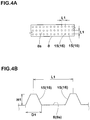
Fig. 4A is a partial plan view showing an arrangement of small protruding portions formed as truncated conical protrusions. -
Fig. 4B is a cross-sectional view of the truncated conical protrusions. -
Fig. 5A is a partial perspective view showing an arrangement and cross sections of the small protruding portions formed as rib-shaped protrusions. -
Fig. 5B is a partial perspective view showing another arrangement and the cross sections of the small protruding portions formed as the rib-shaped protrusions. - An embodiment of the present invention will now be described below in detail.
- As shown in
Fig. 1 , a tyre 1 in this embodiment is provided with one or moremark indicating portions 3 in at least one ofsidewall portions 2. Each of themark indicating portions 3 is provided with a reference surface (x) provided on a surface (2s) of a respective one of thesidewall portions 2 and one ormore marks 4 formed on the reference surface (x). In this embodiment, each of themark indicating portions 3 is provided with abase portion 5 which projects stepwise from the surface (2s) of a respective one of thesidewall portions 2 at a constant height (H5) (that is, a top surface of the base portion is not inclined with respect to the surface (2s)) and a surface (5s) of thebase portion 5 forms the reference surface (x). - Each of the
marks 4 is a letter, a symbol, a figure, and the like for representing the manufacturer name, brand name, size, and the like of the tyre, and in this embodiment, a case is shown in which a brand name consisting of a plurality of themarks 4 is formed on the reference surface (x). Themarks 4 are protruded from the reference surface (x) at a small height. - As shown in
Fig. 2 , aserration portion 7 in which a plurality ofridges 6 is arranged in parallel is formed on at least a part of a surface (4s) of each of themarks 4. In this embodiment, a case is shown in which the surface (4s) of each of themarks 4 is composed of theserration portion 7 and an edgingportion 8. The edgingportion 8 extends along an outer circumference of a respective one of themarks 4 to surround theserration portion 7 thereof. As shown inFig. 3A , it is preferred that the edgingportion 8 has a height equal to or larger than that of theserration portion 7. It is possible that the edgingportions 8 configured as such make contour shapes of the marks clear, therefore, they are helpful for improving the legibility. - As shown in
Figs. 2 and3A , a case is shown in this embodiment where the surface (4s) of each of themarks 4 is inclined with respect to the reference surface (x) in a direction in which a height (H) thereof increases from an end (Fa) on one side in a tyre circumferential direction to an end (Fb) on the other side in the tyre circumferential direction. The height (H) means a height from the reference surface (x). By having the surfaces (4s) inclined as such, it is possible that a stereoscopic effect of themarks 4 is emphasized which can contribute to improvement of the legibility. - In this embodiment, a case is shown where each of the
ridges 6 extends linearly along a tyre radial direction. However, theridges 6 may be inclined with respect to the tyre radial direction or may be configured to extend along the tyre circumferential direction. - Next, as shown in
Fig. 3B , each of theridges 6 is configured such that a cross section taken perpendicular to a length direction of a respective one of theridges 6 has a triangular shape in which a top portion (Q) is sandwiched by a firstoblique side 11 and a secondoblique side 12, or a trapezoidal shape such that the top portion (Q) is cut off. In this embodiment, a case is shown where the cross section is the triangular shape. Note that a height (h) of each of theridges 6 and pitches (p) theridges 6 can be set based on custom. Normally, it is preferred that the height (h) is in the range of from 0.15 to 1.0 mm and the pitch (p) is in the range of from 0.5 to 2.0 times the height (h), - In the cross section of each of the
ridges 6, an angle θ1 of the firstoblique side 11 with respect to the reference surface (x) is different from an angle θ2 of the secondoblique side 12 with respect to the reference surface (x). The angles θ1 and θ2 are indicated by angles on a side of an interior angle. In this embodiment, a case is shown in which the angle θ1 is smaller than the angle θ2, that is thefirst oblique side 11 is mildly sloped as compared with thesecond oblique side 12. - with such a configuration, an area of an inclined surface (S1) having the
first oblique side 11 which is mildly sloped becomes large, therefore, it is possible that the amount of reflected light is increased. Further, it is possible that a difference in light amount is provided between the inclined surface (S1) having thefirst oblique side 11 and an inclined surface (S2) having thesecond oblique side 12, therefore, it is possible that a large difference in contrast is brought about between when viewed from one side and when viewed from the other side. And by a synergistic effect of these, it becomes possible that the legibility is improved. - If a difference |θ1-θ2| between the angle θ1 and the angle θ2 is small, the effect described above is not sufficiently exerted. Thereby, the difference 181-821 is preferably not less than 10 degrees, more preferably not less than 20 degrees, and further preferably not less than 30 degrees. Note that if the angle θ1 or θ2 is more than 90 degrees, undercut occurs, therefore, it is possible that rubber chipping occurs in the ridges when the tyre is removed from a vulcanization mold. Thereby, it is preferred that the angle θ1 or θ2 is not more than 90 degrees.
- Note that, as described above, when each of the surfaces (4s) of the
marks 4 is inclined in the direction in which the height (H) increases from the end (Fa) on one side to the end (Fb) on the other side in the tyre circumferential direction, it is preferred that thefirst oblique side 11 which is mildly sloped is arranged on a side of the end (Fa) on one side in the tyre circumferential direction. Thereby, it is possible that the legibility of themarks 4 is further improved by the synergistic effect of the stereoscopic effect of themarks 4 due to the inclination of the surfaces (4s) and increase in the contrast due to the angle difference |θ1-θ2|. - Further, as shown in
Figs. 4A and 4B , it is preferred that each of theedging portions 8 is provided with a plurality of small protrudingportions 15 each protruding from a surface (8s) of a respective one of theedging portions 8, that is the surface (8s) is a surface of the edging portion other than the small protruding portions. In this embodiment, a case where each of the small protrudingportions 15 is a truncatedconical protrusion 16 having a smaller diameter on a side of an upper end thereof is shown. It is preferred that each of the truncatedconical protrusions 16 has a maximum diameter (D1) in the range of from 50 to 1000 micro meters and a protruding height (H1) from the surface (8s) of a respective one of theedging portions 8 in the range of from 50 to 1000 micro meters, and that a distance (L1) between centers of the small protrudingportions 15 adjacent to each other is in the range of from 200 to 1000 micro meters. - It is possible that the truncated
conical protrusions 16 configured as such irregularly reflect light and make the surfaces (8s) of theedging portions 8 look black. Thereby, it is possible that the contour shapes of themarks 4 are made clearer, therefore, it is possible that the legibility of themarks 4 is further improved. As a result of research by the present inventor, when the maximum diameter (D1) and the protruding height (H1) of each of the truncatedconical protrusions 16, and the distance (L1) of the truncatedconical protrusions 16 are outside the above ranges, theedging portions 8 looks whitish due to the reflection of light, therefore, the contrast difference from theserration portions 7 tends to be decreased. Note that by configuring each of the small protrudingportions 15 to have a truncated cone shape, it is possible that the reflection of light is further suppressed while the strength is increased as compared with a cylindrical shape. - In this embodiment, a case is shown in which the truncated
conical protrusions 16 are arranged in a grid pattern, but they may be arranged in a staggered pattern, or may be randomly arranged as long as the distance (L1) satisfies the above range. -
Figs, 5A and 5B show another embodiment of the small protrudingportions 15. In this embodiment, a case is shown where each of the small protrudingportions 15 is a rib-shapedprotrusion 17 having a trapezoidal cross section with a thickness thereof decreasing toward an upper end thereof. The rib-shapedprotrusions 17 can be arranged parallel to each other as shown inFig, 5A , or they can be arranged so as not to be parallel to each other (non-parallel) as shown inFig. 5B . It is preferred that each of the rib-shapedprotrusions 17 has a maximum thickness (D2) in the range of from 20 to 1000 micro meters and a protruding height (H2) in the range of from 200 to 500 micro meters, and that a distance (L2) between the rib-shapedprotrusions 17 adjacent to each other is in the range of from 10 to 800 micro meters. Note that in a case where the rib-shapedprotrusions 17 are arranged in the non-parallel manner, it is preferred that an average value of a maximum value (L2max) and a minimum value (L2min) of the distance (L2) is in the range of from 10 to 800 micro meters. - As is the case with the truncated
conical protrusions 16, it is possible that the rib-shapedprotrusion 17 irregularly reflect light and make the surfaces (8s) of theedging portions 8 look black. Thereby, it is possible that the contour shapes of themarks 4 are made clearer, therefore, it is possible that the legibility of themarks 4 is further improved. As a result of research by the present inventor, when the maximum thickness (D2) and the protruding height (H2) of each of the rib-shapedprotrusions 17, and the distance (L2) of the rib-shapedprotrusions 17 are outside the above ranges, theedging portions 8 look whitish due to the reflection of light, therefore, the contrast difference from theserration portions 7 tends to be decreased. Note that, from a point of view of the contrast, it is more preferred that the rib-shapedprotrusions 17 are arranged in the non-parallel manner. - Further, in addition to extending straight, each of the
ridges 6 may be curved in an arc shape, for example. Furthermore, in each of themark indicating portions 3, it is possible that themarks 4 are directly formed on the surface (2s) of a respective one of thesidewall portions 2 without having thebase portion 5 formed thereon. In this case, the surface (2s) of thesidewall portion 2 forms the reference surface (X). In this case, in order to distinguish themark indicating portions 3 from other portions, it is preferred that the surface (2s) of each of thesidewall portions 2 is provided with a rib and the like having a small height and surrounding each of themark indicating portions 3. - while detailed description has been made of the tyre as especially preferred embodiments of the present invention, the present invention can be embodied in various forms without being limited to the illustrated embodiments.
- Tyres provided with the
marks 4 on the surfaces (2s) of thesidewall portions 2 were made by way of test according to the specifications listed in Table 1, and then the legibility of themarks 4 was compared. The height (h) (0.5 mm) and the pitch (p) (1.2 mm) of the ridges were the same for all of the test tyres. - In Examples 1, 2, and 5 to 7, an inclination angle of the surface (4s) of each of the
marks 4 was 7 degrees. Further, in Reference 1 and Example 3 and 4, the height (H) of the surface (4s) of each of themarks 4 from the reference surface (X) was equal to an average value of the heights at the end (Fa) on one side and at the end (Fb) on the other side in the Examples 1, 2, and 5 to 7. In the Examples 1 and 4 to 7, the surfaces of the edging portions were provided with the small protruding portions. In the Examples 1, 4, and 5, the small protruding portions were the truncated conical protrusions each having the maximum diameter (D1) of 320 micro meters and the protruding height (H1) of 500 micro meters, and distance (L1) was 400 micro meters. In the Examples 6 and 7, the small protruding portions were the rib-shaped protrusions each having the maximum thickness (D2) of 160 micro meters and the protruding height (H2) of 200 micro meters, and the distance (L2) was 200 micro meters. - The legibility was evaluated by a visual observation and the evaluation is indicated by an index based on the Reference 1 being 100, wherein a larger numerical value is better.
Table 1. Ref.1 Ex.1 Ex.2 Ex.3 Ex.4 Ex.5 Ex.6 Ex.7 Angle difference |θ1-θ2| of Ridge 0 50 [degree] Inclination of Surface of Mark Absent Present Absent Present Small protruding portions on Surface of Edging portion Absent Truncated conical protrusion Absent Absent Truncated conical protrusion Truncated conical protrusion Rib-shaped protrusion (parallel) Rib-shaped protrusion (non-parallel) Legibility 100 115 110 105 110 120 130 135 - As shown in Table 1, it was confirmed that the tyres as the Examples showed excellent legibility of the marks.
Claims (11)
- A tyre comprising a sidewall portion provided with a mark indicating portion having one or more marks, wherein
the mark indicating portion comprises a reference surface provided on a surface of the sidewall portion and the one or more marks formed on the reference surface,
at least a part of a surface of the or each mark is provided with a serration portion in which a plurality of ridges is arranged in parallel,
each of the ridges has a triangular or trapezoidal cross section taken perpendicular to a length direction thereof having a first oblique side and a second oblique side, and
an angle θ1 of the first oblique side with respect to the reference surface is different from an angle θ2 of the second oblique side with respect to the reference surface. - The tyre according to claim 1, wherein
a difference 181-821 between the angle θ1 and the angle θ2 is not less than 10 degrees. - The tyre according to claim 1 or 2, wherein
the or each mark is provided with an edging portion extending along an outer circumference of the or each mark to surround the serration portion thereof, and
the edging portion has a height equal to or larger than that of the serration portion. - The tyre according to any one of claims 1 to 3, wherein
the edging portion is provided with a plurality of small protruding portions each protruding from a surface of the edging portion. - The tyre according to claim 4, wherein
each of the small protruding portions is a truncated conical protrusion having a smaller diameter on a side of an upper end thereof. - The tyre according to claim 5, wherein
each of the truncated conical protrusions has a maximum diameter in a range of from 50 to 1000 micro meters and a protruding height in a range of from 50 to 1000 micro meters, and
a distance between centers of the truncated conical protrusions adjacent to each other is in a range of from 200 to 1000 micro meters. - The tyre according to claim 4, wherein
each of the small protruding portions is a rib-shaped protrusion having a trapezoidal cross section with a thickness thereof decreasing toward an upper end thereof, and
the rib-shaped protrusions are arranged in parallel to each other or in a non-parallel manner. - The tyre according to claim 7, wherein
each of the rib-shaped protrusions has a maximum thickness in a range of from 20 to 1000 micro meters and a protruding height in a range of from 200 to 500 micro meters, and
a distance between the rib-shaped protrusions adjacent to each other is in a range of from 10 to 800 micro meters. - The tyre according to any one of claims 1 to 8, wherein
the surface of the or each mark is inclined with respect to the reference surface in a direction in which a height thereof increases from one side to the other side in a tyre circumferential direction. - The tyre according to claim 9, wherein
in each of the ridges, a mildly sloped one of the first oblique side and the second oblique side is arranged on the one side in the tyre circumferential direction. - The tyre according to any one of claims 1 to 10, wherein
the mark indicating portion is provided with a base portion projecting from the surface of the sidewall portion at a constant height, and
a surface of the base portion forms the reference surface.
Applications Claiming Priority (1)
| Application Number | Priority Date | Filing Date | Title |
|---|---|---|---|
| JP2018034038A JP7069827B2 (en) | 2018-02-28 | 2018-02-28 | tire |
Publications (2)
| Publication Number | Publication Date |
|---|---|
| EP3533638A1 true EP3533638A1 (en) | 2019-09-04 |
| EP3533638B1 EP3533638B1 (en) | 2021-03-10 |
Family
ID=65228404
Family Applications (1)
| Application Number | Title | Priority Date | Filing Date |
|---|---|---|---|
| EP19153408.0A Active EP3533638B1 (en) | 2018-02-28 | 2019-01-24 | Tyre |
Country Status (3)
| Country | Link |
|---|---|
| US (1) | US11072207B2 (en) |
| EP (1) | EP3533638B1 (en) |
| JP (1) | JP7069827B2 (en) |
Cited By (1)
| Publication number | Priority date | Publication date | Assignee | Title |
|---|---|---|---|---|
| EP3792082A1 (en) * | 2019-09-10 | 2021-03-17 | Continental Reifen Deutschland GmbH | Vehicle tyre comprising a marking area |
Families Citing this family (2)
| Publication number | Priority date | Publication date | Assignee | Title |
|---|---|---|---|---|
| JP2022166645A (en) * | 2021-04-21 | 2022-11-02 | Toyo Tire株式会社 | pneumatic tire |
| JP2024082469A (en) | 2022-12-08 | 2024-06-20 | Toyo Tire株式会社 | Pneumatic tires |
Citations (8)
| Publication number | Priority date | Publication date | Assignee | Title |
|---|---|---|---|---|
| GB2008062A (en) * | 1977-11-18 | 1979-05-31 | Goodyear Tire & Rubber | Indicia for rubber articles |
| JPS60160207U (en) * | 1984-04-03 | 1985-10-24 | 住友ゴム工業株式会社 | tire |
| JPH0986106A (en) | 1995-09-28 | 1997-03-31 | Sumitomo Rubber Ind Ltd | Pneumatic tire |
| JP2003175707A (en) * | 2001-12-10 | 2003-06-24 | Yokohama Rubber Co Ltd:The | Pneumatic tire |
| EP1625952A1 (en) * | 2004-08-13 | 2006-02-15 | The Goodyear Tire & Rubber Company | Tire with raised indicia |
| JP2008265502A (en) * | 2007-04-19 | 2008-11-06 | Yokohama Rubber Co Ltd:The | Pneumatic tire |
| US8672008B2 (en) * | 2009-09-28 | 2014-03-18 | Compagnie Generale Des Etablissements Michelin | High-contrast tire pattern and method for producing same |
| JP2014223914A (en) * | 2014-09-01 | 2014-12-04 | 住友ゴム工業株式会社 | Pneumatic tire |
Family Cites Families (10)
| Publication number | Priority date | Publication date | Assignee | Title |
|---|---|---|---|---|
| JPS6092604U (en) * | 1983-11-30 | 1985-06-25 | 住友ゴム工業株式会社 | tire |
| JP3072921B2 (en) * | 1991-07-04 | 2000-08-07 | 住友ゴム工業株式会社 | Pneumatic tire |
| JP3652809B2 (en) * | 1996-09-13 | 2005-05-25 | 株式会社ブリヂストン | Pneumatic tire |
| US6253815B1 (en) * | 1998-08-14 | 2001-07-03 | Michelin Recherche Et Techniques S.A. | Design pattern for a tire |
| KR20030047450A (en) | 2001-12-10 | 2003-06-18 | 한국타이어 주식회사 | Sidewall form of a vehicle tire |
| JP2006224704A (en) | 2005-02-15 | 2006-08-31 | Bridgestone Corp | Pneumatic tire |
| JP5160345B2 (en) | 2008-08-26 | 2013-03-13 | 東洋ゴム工業株式会社 | Pneumatic tire |
| JP4687811B2 (en) | 2009-04-10 | 2011-05-25 | 横浜ゴム株式会社 | Pneumatic tire |
| JP2016132386A (en) | 2015-01-21 | 2016-07-25 | 横浜ゴム株式会社 | Pneumatic tire |
| JP6747932B2 (en) * | 2016-10-11 | 2020-08-26 | Toyo Tire株式会社 | Pneumatic tire |
-
2018
- 2018-02-28 JP JP2018034038A patent/JP7069827B2/en active Active
-
2019
- 2019-01-24 EP EP19153408.0A patent/EP3533638B1/en active Active
- 2019-02-14 US US16/275,517 patent/US11072207B2/en active Active
Patent Citations (8)
| Publication number | Priority date | Publication date | Assignee | Title |
|---|---|---|---|---|
| GB2008062A (en) * | 1977-11-18 | 1979-05-31 | Goodyear Tire & Rubber | Indicia for rubber articles |
| JPS60160207U (en) * | 1984-04-03 | 1985-10-24 | 住友ゴム工業株式会社 | tire |
| JPH0986106A (en) | 1995-09-28 | 1997-03-31 | Sumitomo Rubber Ind Ltd | Pneumatic tire |
| JP2003175707A (en) * | 2001-12-10 | 2003-06-24 | Yokohama Rubber Co Ltd:The | Pneumatic tire |
| EP1625952A1 (en) * | 2004-08-13 | 2006-02-15 | The Goodyear Tire & Rubber Company | Tire with raised indicia |
| JP2008265502A (en) * | 2007-04-19 | 2008-11-06 | Yokohama Rubber Co Ltd:The | Pneumatic tire |
| US8672008B2 (en) * | 2009-09-28 | 2014-03-18 | Compagnie Generale Des Etablissements Michelin | High-contrast tire pattern and method for producing same |
| JP2014223914A (en) * | 2014-09-01 | 2014-12-04 | 住友ゴム工業株式会社 | Pneumatic tire |
Cited By (1)
| Publication number | Priority date | Publication date | Assignee | Title |
|---|---|---|---|---|
| EP3792082A1 (en) * | 2019-09-10 | 2021-03-17 | Continental Reifen Deutschland GmbH | Vehicle tyre comprising a marking area |
Also Published As
| Publication number | Publication date |
|---|---|
| US20190263195A1 (en) | 2019-08-29 |
| JP7069827B2 (en) | 2022-05-18 |
| JP2019147495A (en) | 2019-09-05 |
| EP3533638B1 (en) | 2021-03-10 |
| US11072207B2 (en) | 2021-07-27 |
Similar Documents
| Publication | Publication Date | Title |
|---|---|---|
| EP3533633B1 (en) | Tyre | |
| EP3546251B1 (en) | Tyre | |
| EP3533638B1 (en) | Tyre | |
| EP3409508B1 (en) | Tire | |
| US11325428B2 (en) | Tire | |
| US11273675B2 (en) | Tire | |
| EP3489040B1 (en) | Tire | |
| EP2781376A1 (en) | Pneumatic tire | |
| EP3533635B1 (en) | Tyre | |
| EP3666555B1 (en) | Tire | |
| EP3546252A1 (en) | Tyre | |
| EP3511180B1 (en) | Tyre | |
| EP3533634B1 (en) | Tyre | |
| EP3533636B1 (en) | Tyre | |
| US11097574B2 (en) | Tyre | |
| US12570111B2 (en) | Pneumatic tire | |
| US20240190182A1 (en) | Pneumatic tire | |
| EP3822097A1 (en) | Tire |
Legal Events
| Date | Code | Title | Description |
|---|---|---|---|
| PUAI | Public reference made under article 153(3) epc to a published international application that has entered the european phase |
Free format text: ORIGINAL CODE: 0009012 |
|
| STAA | Information on the status of an ep patent application or granted ep patent |
Free format text: STATUS: THE APPLICATION HAS BEEN PUBLISHED |
|
| AK | Designated contracting states |
Kind code of ref document: A1 Designated state(s): AL AT BE BG CH CY CZ DE DK EE ES FI FR GB GR HR HU IE IS IT LI LT LU LV MC MK MT NL NO PL PT RO RS SE SI SK SM TR |
|
| AX | Request for extension of the european patent |
Extension state: BA ME |
|
| STAA | Information on the status of an ep patent application or granted ep patent |
Free format text: STATUS: REQUEST FOR EXAMINATION WAS MADE |
|
| 17P | Request for examination filed |
Effective date: 20200206 |
|
| RBV | Designated contracting states (corrected) |
Designated state(s): AL AT BE BG CH CY CZ DE DK EE ES FI FR GB GR HR HU IE IS IT LI LT LU LV MC MK MT NL NO PL PT RO RS SE SI SK SM TR |
|
| STAA | Information on the status of an ep patent application or granted ep patent |
Free format text: STATUS: EXAMINATION IS IN PROGRESS |
|
| 17Q | First examination report despatched |
Effective date: 20200406 |
|
| GRAP | Despatch of communication of intention to grant a patent |
Free format text: ORIGINAL CODE: EPIDOSNIGR1 |
|
| STAA | Information on the status of an ep patent application or granted ep patent |
Free format text: STATUS: GRANT OF PATENT IS INTENDED |
|
| INTG | Intention to grant announced |
Effective date: 20201014 |
|
| GRAS | Grant fee paid |
Free format text: ORIGINAL CODE: EPIDOSNIGR3 |
|
| GRAA | (expected) grant |
Free format text: ORIGINAL CODE: 0009210 |
|
| STAA | Information on the status of an ep patent application or granted ep patent |
Free format text: STATUS: THE PATENT HAS BEEN GRANTED |
|
| AK | Designated contracting states |
Kind code of ref document: B1 Designated state(s): AL AT BE BG CH CY CZ DE DK EE ES FI FR GB GR HR HU IE IS IT LI LT LU LV MC MK MT NL NO PL PT RO RS SE SI SK SM TR |
|
| REG | Reference to a national code |
Ref country code: GB Ref legal event code: FG4D |
|
| REG | Reference to a national code |
Ref country code: CH Ref legal event code: EP Ref country code: AT Ref legal event code: REF Ref document number: 1369408 Country of ref document: AT Kind code of ref document: T Effective date: 20210315 |
|
| REG | Reference to a national code |
Ref country code: IE Ref legal event code: FG4D |
|
| REG | Reference to a national code |
Ref country code: DE Ref legal event code: R096 Ref document number: 602019002993 Country of ref document: DE |
|
| REG | Reference to a national code |
Ref country code: LT Ref legal event code: MG9D |
|
| PG25 | Lapsed in a contracting state [announced via postgrant information from national office to epo] |
Ref country code: HR Free format text: LAPSE BECAUSE OF FAILURE TO SUBMIT A TRANSLATION OF THE DESCRIPTION OR TO PAY THE FEE WITHIN THE PRESCRIBED TIME-LIMIT Effective date: 20210310 Ref country code: GR Free format text: LAPSE BECAUSE OF FAILURE TO SUBMIT A TRANSLATION OF THE DESCRIPTION OR TO PAY THE FEE WITHIN THE PRESCRIBED TIME-LIMIT Effective date: 20210611 Ref country code: FI Free format text: LAPSE BECAUSE OF FAILURE TO SUBMIT A TRANSLATION OF THE DESCRIPTION OR TO PAY THE FEE WITHIN THE PRESCRIBED TIME-LIMIT Effective date: 20210310 Ref country code: BG Free format text: LAPSE BECAUSE OF FAILURE TO SUBMIT A TRANSLATION OF THE DESCRIPTION OR TO PAY THE FEE WITHIN THE PRESCRIBED TIME-LIMIT Effective date: 20210610 Ref country code: NO Free format text: LAPSE BECAUSE OF FAILURE TO SUBMIT A TRANSLATION OF THE DESCRIPTION OR TO PAY THE FEE WITHIN THE PRESCRIBED TIME-LIMIT Effective date: 20210610 Ref country code: LT Free format text: LAPSE BECAUSE OF FAILURE TO SUBMIT A TRANSLATION OF THE DESCRIPTION OR TO PAY THE FEE WITHIN THE PRESCRIBED TIME-LIMIT Effective date: 20210310 |
|
| REG | Reference to a national code |
Ref country code: AT Ref legal event code: MK05 Ref document number: 1369408 Country of ref document: AT Kind code of ref document: T Effective date: 20210310 |
|
| REG | Reference to a national code |
Ref country code: NL Ref legal event code: MP Effective date: 20210310 |
|
| PG25 | Lapsed in a contracting state [announced via postgrant information from national office to epo] |
Ref country code: SE Free format text: LAPSE BECAUSE OF FAILURE TO SUBMIT A TRANSLATION OF THE DESCRIPTION OR TO PAY THE FEE WITHIN THE PRESCRIBED TIME-LIMIT Effective date: 20210310 Ref country code: RS Free format text: LAPSE BECAUSE OF FAILURE TO SUBMIT A TRANSLATION OF THE DESCRIPTION OR TO PAY THE FEE WITHIN THE PRESCRIBED TIME-LIMIT Effective date: 20210310 Ref country code: LV Free format text: LAPSE BECAUSE OF FAILURE TO SUBMIT A TRANSLATION OF THE DESCRIPTION OR TO PAY THE FEE WITHIN THE PRESCRIBED TIME-LIMIT Effective date: 20210310 |
|
| PG25 | Lapsed in a contracting state [announced via postgrant information from national office to epo] |
Ref country code: NL Free format text: LAPSE BECAUSE OF FAILURE TO SUBMIT A TRANSLATION OF THE DESCRIPTION OR TO PAY THE FEE WITHIN THE PRESCRIBED TIME-LIMIT Effective date: 20210310 |
|
| PG25 | Lapsed in a contracting state [announced via postgrant information from national office to epo] |
Ref country code: EE Free format text: LAPSE BECAUSE OF FAILURE TO SUBMIT A TRANSLATION OF THE DESCRIPTION OR TO PAY THE FEE WITHIN THE PRESCRIBED TIME-LIMIT Effective date: 20210310 Ref country code: CZ Free format text: LAPSE BECAUSE OF FAILURE TO SUBMIT A TRANSLATION OF THE DESCRIPTION OR TO PAY THE FEE WITHIN THE PRESCRIBED TIME-LIMIT Effective date: 20210310 Ref country code: SM Free format text: LAPSE BECAUSE OF FAILURE TO SUBMIT A TRANSLATION OF THE DESCRIPTION OR TO PAY THE FEE WITHIN THE PRESCRIBED TIME-LIMIT Effective date: 20210310 Ref country code: AT Free format text: LAPSE BECAUSE OF FAILURE TO SUBMIT A TRANSLATION OF THE DESCRIPTION OR TO PAY THE FEE WITHIN THE PRESCRIBED TIME-LIMIT Effective date: 20210310 |
|
| PG25 | Lapsed in a contracting state [announced via postgrant information from national office to epo] |
Ref country code: SK Free format text: LAPSE BECAUSE OF FAILURE TO SUBMIT A TRANSLATION OF THE DESCRIPTION OR TO PAY THE FEE WITHIN THE PRESCRIBED TIME-LIMIT Effective date: 20210310 Ref country code: RO Free format text: LAPSE BECAUSE OF FAILURE TO SUBMIT A TRANSLATION OF THE DESCRIPTION OR TO PAY THE FEE WITHIN THE PRESCRIBED TIME-LIMIT Effective date: 20210310 Ref country code: PT Free format text: LAPSE BECAUSE OF FAILURE TO SUBMIT A TRANSLATION OF THE DESCRIPTION OR TO PAY THE FEE WITHIN THE PRESCRIBED TIME-LIMIT Effective date: 20210712 Ref country code: PL Free format text: LAPSE BECAUSE OF FAILURE TO SUBMIT A TRANSLATION OF THE DESCRIPTION OR TO PAY THE FEE WITHIN THE PRESCRIBED TIME-LIMIT Effective date: 20210310 Ref country code: IS Free format text: LAPSE BECAUSE OF FAILURE TO SUBMIT A TRANSLATION OF THE DESCRIPTION OR TO PAY THE FEE WITHIN THE PRESCRIBED TIME-LIMIT Effective date: 20210710 |
|
| REG | Reference to a national code |
Ref country code: DE Ref legal event code: R097 Ref document number: 602019002993 Country of ref document: DE |
|
| PLBE | No opposition filed within time limit |
Free format text: ORIGINAL CODE: 0009261 |
|
| STAA | Information on the status of an ep patent application or granted ep patent |
Free format text: STATUS: NO OPPOSITION FILED WITHIN TIME LIMIT |
|
| PG25 | Lapsed in a contracting state [announced via postgrant information from national office to epo] |
Ref country code: DK Free format text: LAPSE BECAUSE OF FAILURE TO SUBMIT A TRANSLATION OF THE DESCRIPTION OR TO PAY THE FEE WITHIN THE PRESCRIBED TIME-LIMIT Effective date: 20210310 Ref country code: AL Free format text: LAPSE BECAUSE OF FAILURE TO SUBMIT A TRANSLATION OF THE DESCRIPTION OR TO PAY THE FEE WITHIN THE PRESCRIBED TIME-LIMIT Effective date: 20210310 Ref country code: ES Free format text: LAPSE BECAUSE OF FAILURE TO SUBMIT A TRANSLATION OF THE DESCRIPTION OR TO PAY THE FEE WITHIN THE PRESCRIBED TIME-LIMIT Effective date: 20210310 |
|
| 26N | No opposition filed |
Effective date: 20211213 |
|
| PG25 | Lapsed in a contracting state [announced via postgrant information from national office to epo] |
Ref country code: SI Free format text: LAPSE BECAUSE OF FAILURE TO SUBMIT A TRANSLATION OF THE DESCRIPTION OR TO PAY THE FEE WITHIN THE PRESCRIBED TIME-LIMIT Effective date: 20210310 |
|
| PG25 | Lapsed in a contracting state [announced via postgrant information from national office to epo] |
Ref country code: IT Free format text: LAPSE BECAUSE OF FAILURE TO SUBMIT A TRANSLATION OF THE DESCRIPTION OR TO PAY THE FEE WITHIN THE PRESCRIBED TIME-LIMIT Effective date: 20210310 |
|
| PG25 | Lapsed in a contracting state [announced via postgrant information from national office to epo] |
Ref country code: IS Free format text: LAPSE BECAUSE OF FAILURE TO SUBMIT A TRANSLATION OF THE DESCRIPTION OR TO PAY THE FEE WITHIN THE PRESCRIBED TIME-LIMIT Effective date: 20210710 |
|
| PG25 | Lapsed in a contracting state [announced via postgrant information from national office to epo] |
Ref country code: MC Free format text: LAPSE BECAUSE OF FAILURE TO SUBMIT A TRANSLATION OF THE DESCRIPTION OR TO PAY THE FEE WITHIN THE PRESCRIBED TIME-LIMIT Effective date: 20210310 |
|
| REG | Reference to a national code |
Ref country code: CH Ref legal event code: PL |
|
| REG | Reference to a national code |
Ref country code: BE Ref legal event code: MM Effective date: 20220131 |
|
| PG25 | Lapsed in a contracting state [announced via postgrant information from national office to epo] |
Ref country code: LU Free format text: LAPSE BECAUSE OF NON-PAYMENT OF DUE FEES Effective date: 20220124 |
|
| PG25 | Lapsed in a contracting state [announced via postgrant information from national office to epo] |
Ref country code: BE Free format text: LAPSE BECAUSE OF NON-PAYMENT OF DUE FEES Effective date: 20220131 |
|
| PG25 | Lapsed in a contracting state [announced via postgrant information from national office to epo] |
Ref country code: LI Free format text: LAPSE BECAUSE OF NON-PAYMENT OF DUE FEES Effective date: 20220131 Ref country code: CH Free format text: LAPSE BECAUSE OF NON-PAYMENT OF DUE FEES Effective date: 20220131 |
|
| PG25 | Lapsed in a contracting state [announced via postgrant information from national office to epo] |
Ref country code: IE Free format text: LAPSE BECAUSE OF NON-PAYMENT OF DUE FEES Effective date: 20220124 |
|
| P01 | Opt-out of the competence of the unified patent court (upc) registered |
Effective date: 20230510 |
|
| GBPC | Gb: european patent ceased through non-payment of renewal fee |
Effective date: 20230124 |
|
| PG25 | Lapsed in a contracting state [announced via postgrant information from national office to epo] |
Ref country code: GB Free format text: LAPSE BECAUSE OF NON-PAYMENT OF DUE FEES Effective date: 20230124 |
|
| PG25 | Lapsed in a contracting state [announced via postgrant information from national office to epo] |
Ref country code: MK Free format text: LAPSE BECAUSE OF FAILURE TO SUBMIT A TRANSLATION OF THE DESCRIPTION OR TO PAY THE FEE WITHIN THE PRESCRIBED TIME-LIMIT Effective date: 20210310 Ref country code: CY Free format text: LAPSE BECAUSE OF FAILURE TO SUBMIT A TRANSLATION OF THE DESCRIPTION OR TO PAY THE FEE WITHIN THE PRESCRIBED TIME-LIMIT Effective date: 20210310 |
|
| PG25 | Lapsed in a contracting state [announced via postgrant information from national office to epo] |
Ref country code: HU Free format text: LAPSE BECAUSE OF FAILURE TO SUBMIT A TRANSLATION OF THE DESCRIPTION OR TO PAY THE FEE WITHIN THE PRESCRIBED TIME-LIMIT; INVALID AB INITIO Effective date: 20190124 |
|
| PG25 | Lapsed in a contracting state [announced via postgrant information from national office to epo] |
Ref country code: TR Free format text: LAPSE BECAUSE OF FAILURE TO SUBMIT A TRANSLATION OF THE DESCRIPTION OR TO PAY THE FEE WITHIN THE PRESCRIBED TIME-LIMIT Effective date: 20210310 |
|
| PG25 | Lapsed in a contracting state [announced via postgrant information from national office to epo] |
Ref country code: MT Free format text: LAPSE BECAUSE OF FAILURE TO SUBMIT A TRANSLATION OF THE DESCRIPTION OR TO PAY THE FEE WITHIN THE PRESCRIBED TIME-LIMIT Effective date: 20210310 |
|
| PGFP | Annual fee paid to national office [announced via postgrant information from national office to epo] |
Ref country code: FR Payment date: 20251128 Year of fee payment: 8 |
|
| PGFP | Annual fee paid to national office [announced via postgrant information from national office to epo] |
Ref country code: DE Payment date: 20251203 Year of fee payment: 8 |