EP3533580A1 - Method for manufacturing fiber reinforced plastic molded body - Google Patents
Method for manufacturing fiber reinforced plastic molded body Download PDFInfo
- Publication number
- EP3533580A1 EP3533580A1 EP17865293.9A EP17865293A EP3533580A1 EP 3533580 A1 EP3533580 A1 EP 3533580A1 EP 17865293 A EP17865293 A EP 17865293A EP 3533580 A1 EP3533580 A1 EP 3533580A1
- Authority
- EP
- European Patent Office
- Prior art keywords
- molding
- solid body
- thermoplastic solid
- fiber reinforced
- reinforced plastic
- Prior art date
- Legal status (The legal status is an assumption and is not a legal conclusion. Google has not performed a legal analysis and makes no representation as to the accuracy of the status listed.)
- Granted
Links
Images


Classifications
-
- B—PERFORMING OPERATIONS; TRANSPORTING
- B29—WORKING OF PLASTICS; WORKING OF SUBSTANCES IN A PLASTIC STATE IN GENERAL
- B29C—SHAPING OR JOINING OF PLASTICS; SHAPING OF MATERIAL IN A PLASTIC STATE, NOT OTHERWISE PROVIDED FOR; AFTER-TREATMENT OF THE SHAPED PRODUCTS, e.g. REPAIRING
- B29C70/00—Shaping composites, i.e. plastics material comprising reinforcements, fillers or preformed parts, e.g. inserts
- B29C70/04—Shaping composites, i.e. plastics material comprising reinforcements, fillers or preformed parts, e.g. inserts comprising reinforcements only, e.g. self-reinforcing plastics
- B29C70/28—Shaping operations therefor
- B29C70/40—Shaping or impregnating by compression not applied
- B29C70/42—Shaping or impregnating by compression not applied for producing articles of definite length, i.e. discrete articles
- B29C70/46—Shaping or impregnating by compression not applied for producing articles of definite length, i.e. discrete articles using matched moulds, e.g. for deforming sheet moulding compounds [SMC] or prepregs
-
- B—PERFORMING OPERATIONS; TRANSPORTING
- B29—WORKING OF PLASTICS; WORKING OF SUBSTANCES IN A PLASTIC STATE IN GENERAL
- B29C—SHAPING OR JOINING OF PLASTICS; SHAPING OF MATERIAL IN A PLASTIC STATE, NOT OTHERWISE PROVIDED FOR; AFTER-TREATMENT OF THE SHAPED PRODUCTS, e.g. REPAIRING
- B29C33/00—Moulds or cores; Details thereof or accessories therefor
- B29C33/44—Moulds or cores; Details thereof or accessories therefor with means for, or specially constructed to facilitate, the removal of articles, e.g. of undercut articles
- B29C33/52—Moulds or cores; Details thereof or accessories therefor with means for, or specially constructed to facilitate, the removal of articles, e.g. of undercut articles soluble or fusible
-
- B—PERFORMING OPERATIONS; TRANSPORTING
- B29—WORKING OF PLASTICS; WORKING OF SUBSTANCES IN A PLASTIC STATE IN GENERAL
- B29C—SHAPING OR JOINING OF PLASTICS; SHAPING OF MATERIAL IN A PLASTIC STATE, NOT OTHERWISE PROVIDED FOR; AFTER-TREATMENT OF THE SHAPED PRODUCTS, e.g. REPAIRING
- B29C43/00—Compression moulding, i.e. applying external pressure to flow the moulding material; Apparatus therefor
- B29C43/003—Compression moulding, i.e. applying external pressure to flow the moulding material; Apparatus therefor characterised by the choice of material
-
- B—PERFORMING OPERATIONS; TRANSPORTING
- B29—WORKING OF PLASTICS; WORKING OF SUBSTANCES IN A PLASTIC STATE IN GENERAL
- B29C—SHAPING OR JOINING OF PLASTICS; SHAPING OF MATERIAL IN A PLASTIC STATE, NOT OTHERWISE PROVIDED FOR; AFTER-TREATMENT OF THE SHAPED PRODUCTS, e.g. REPAIRING
- B29C43/00—Compression moulding, i.e. applying external pressure to flow the moulding material; Apparatus therefor
- B29C43/02—Compression moulding, i.e. applying external pressure to flow the moulding material; Apparatus therefor of articles of definite length, i.e. discrete articles
- B29C43/04—Compression moulding, i.e. applying external pressure to flow the moulding material; Apparatus therefor of articles of definite length, i.e. discrete articles using movable moulds
-
- B—PERFORMING OPERATIONS; TRANSPORTING
- B29—WORKING OF PLASTICS; WORKING OF SUBSTANCES IN A PLASTIC STATE IN GENERAL
- B29C—SHAPING OR JOINING OF PLASTICS; SHAPING OF MATERIAL IN A PLASTIC STATE, NOT OTHERWISE PROVIDED FOR; AFTER-TREATMENT OF THE SHAPED PRODUCTS, e.g. REPAIRING
- B29C43/00—Compression moulding, i.e. applying external pressure to flow the moulding material; Apparatus therefor
- B29C43/02—Compression moulding, i.e. applying external pressure to flow the moulding material; Apparatus therefor of articles of definite length, i.e. discrete articles
- B29C43/10—Isostatic pressing, i.e. using non-rigid pressure-exerting members against rigid parts or dies
-
- B—PERFORMING OPERATIONS; TRANSPORTING
- B29—WORKING OF PLASTICS; WORKING OF SUBSTANCES IN A PLASTIC STATE IN GENERAL
- B29C—SHAPING OR JOINING OF PLASTICS; SHAPING OF MATERIAL IN A PLASTIC STATE, NOT OTHERWISE PROVIDED FOR; AFTER-TREATMENT OF THE SHAPED PRODUCTS, e.g. REPAIRING
- B29C43/00—Compression moulding, i.e. applying external pressure to flow the moulding material; Apparatus therefor
- B29C43/02—Compression moulding, i.e. applying external pressure to flow the moulding material; Apparatus therefor of articles of definite length, i.e. discrete articles
- B29C43/18—Compression moulding, i.e. applying external pressure to flow the moulding material; Apparatus therefor of articles of definite length, i.e. discrete articles incorporating preformed parts or layers, e.g. compression moulding around inserts or for coating articles
-
- B—PERFORMING OPERATIONS; TRANSPORTING
- B29—WORKING OF PLASTICS; WORKING OF SUBSTANCES IN A PLASTIC STATE IN GENERAL
- B29C—SHAPING OR JOINING OF PLASTICS; SHAPING OF MATERIAL IN A PLASTIC STATE, NOT OTHERWISE PROVIDED FOR; AFTER-TREATMENT OF THE SHAPED PRODUCTS, e.g. REPAIRING
- B29C43/00—Compression moulding, i.e. applying external pressure to flow the moulding material; Apparatus therefor
- B29C43/32—Component parts, details or accessories; Auxiliary operations
-
- B—PERFORMING OPERATIONS; TRANSPORTING
- B29—WORKING OF PLASTICS; WORKING OF SUBSTANCES IN A PLASTIC STATE IN GENERAL
- B29C—SHAPING OR JOINING OF PLASTICS; SHAPING OF MATERIAL IN A PLASTIC STATE, NOT OTHERWISE PROVIDED FOR; AFTER-TREATMENT OF THE SHAPED PRODUCTS, e.g. REPAIRING
- B29C43/00—Compression moulding, i.e. applying external pressure to flow the moulding material; Apparatus therefor
- B29C43/32—Component parts, details or accessories; Auxiliary operations
- B29C43/36—Moulds for making articles of definite length, i.e. discrete articles
- B29C43/361—Moulds for making articles of definite length, i.e. discrete articles with pressing members independently movable of the parts for opening or closing the mould, e.g. movable pistons
-
- B—PERFORMING OPERATIONS; TRANSPORTING
- B29—WORKING OF PLASTICS; WORKING OF SUBSTANCES IN A PLASTIC STATE IN GENERAL
- B29C—SHAPING OR JOINING OF PLASTICS; SHAPING OF MATERIAL IN A PLASTIC STATE, NOT OTHERWISE PROVIDED FOR; AFTER-TREATMENT OF THE SHAPED PRODUCTS, e.g. REPAIRING
- B29C43/00—Compression moulding, i.e. applying external pressure to flow the moulding material; Apparatus therefor
- B29C43/02—Compression moulding, i.e. applying external pressure to flow the moulding material; Apparatus therefor of articles of definite length, i.e. discrete articles
- B29C43/10—Isostatic pressing, i.e. using non-rigid pressure-exerting members against rigid parts or dies
- B29C2043/108—Isostatic pressing, i.e. using non-rigid pressure-exerting members against rigid parts or dies using deformable metals, e.g. flowable metals, low melting point eutectic metals, liquified metals
-
- B—PERFORMING OPERATIONS; TRANSPORTING
- B29—WORKING OF PLASTICS; WORKING OF SUBSTANCES IN A PLASTIC STATE IN GENERAL
- B29C—SHAPING OR JOINING OF PLASTICS; SHAPING OF MATERIAL IN A PLASTIC STATE, NOT OTHERWISE PROVIDED FOR; AFTER-TREATMENT OF THE SHAPED PRODUCTS, e.g. REPAIRING
- B29C43/00—Compression moulding, i.e. applying external pressure to flow the moulding material; Apparatus therefor
- B29C43/02—Compression moulding, i.e. applying external pressure to flow the moulding material; Apparatus therefor of articles of definite length, i.e. discrete articles
- B29C43/18—Compression moulding, i.e. applying external pressure to flow the moulding material; Apparatus therefor of articles of definite length, i.e. discrete articles incorporating preformed parts or layers, e.g. compression moulding around inserts or for coating articles
- B29C2043/181—Compression moulding, i.e. applying external pressure to flow the moulding material; Apparatus therefor of articles of definite length, i.e. discrete articles incorporating preformed parts or layers, e.g. compression moulding around inserts or for coating articles encapsulated
-
- B—PERFORMING OPERATIONS; TRANSPORTING
- B29—WORKING OF PLASTICS; WORKING OF SUBSTANCES IN A PLASTIC STATE IN GENERAL
- B29C—SHAPING OR JOINING OF PLASTICS; SHAPING OF MATERIAL IN A PLASTIC STATE, NOT OTHERWISE PROVIDED FOR; AFTER-TREATMENT OF THE SHAPED PRODUCTS, e.g. REPAIRING
- B29C43/00—Compression moulding, i.e. applying external pressure to flow the moulding material; Apparatus therefor
- B29C43/32—Component parts, details or accessories; Auxiliary operations
- B29C2043/3205—Particular pressure exerting means for making definite articles
- B29C2043/3261—Particular pressure exerting means for making definite articles thermal expansion
-
- B—PERFORMING OPERATIONS; TRANSPORTING
- B29—WORKING OF PLASTICS; WORKING OF SUBSTANCES IN A PLASTIC STATE IN GENERAL
- B29C—SHAPING OR JOINING OF PLASTICS; SHAPING OF MATERIAL IN A PLASTIC STATE, NOT OTHERWISE PROVIDED FOR; AFTER-TREATMENT OF THE SHAPED PRODUCTS, e.g. REPAIRING
- B29C43/00—Compression moulding, i.e. applying external pressure to flow the moulding material; Apparatus therefor
- B29C43/32—Component parts, details or accessories; Auxiliary operations
- B29C43/36—Moulds for making articles of definite length, i.e. discrete articles
- B29C43/361—Moulds for making articles of definite length, i.e. discrete articles with pressing members independently movable of the parts for opening or closing the mould, e.g. movable pistons
- B29C2043/3613—Moulds for making articles of definite length, i.e. discrete articles with pressing members independently movable of the parts for opening or closing the mould, e.g. movable pistons applying pressure locally
-
- B—PERFORMING OPERATIONS; TRANSPORTING
- B29—WORKING OF PLASTICS; WORKING OF SUBSTANCES IN A PLASTIC STATE IN GENERAL
- B29C—SHAPING OR JOINING OF PLASTICS; SHAPING OF MATERIAL IN A PLASTIC STATE, NOT OTHERWISE PROVIDED FOR; AFTER-TREATMENT OF THE SHAPED PRODUCTS, e.g. REPAIRING
- B29C43/00—Compression moulding, i.e. applying external pressure to flow the moulding material; Apparatus therefor
- B29C43/32—Component parts, details or accessories; Auxiliary operations
- B29C43/36—Moulds for making articles of definite length, i.e. discrete articles
- B29C2043/3665—Moulds for making articles of definite length, i.e. discrete articles cores or inserts, e.g. pins, mandrels, sliders
- B29C2043/3668—Moulds for making articles of definite length, i.e. discrete articles cores or inserts, e.g. pins, mandrels, sliders destructible or fusible
-
- B—PERFORMING OPERATIONS; TRANSPORTING
- B29—WORKING OF PLASTICS; WORKING OF SUBSTANCES IN A PLASTIC STATE IN GENERAL
- B29C—SHAPING OR JOINING OF PLASTICS; SHAPING OF MATERIAL IN A PLASTIC STATE, NOT OTHERWISE PROVIDED FOR; AFTER-TREATMENT OF THE SHAPED PRODUCTS, e.g. REPAIRING
- B29C43/00—Compression moulding, i.e. applying external pressure to flow the moulding material; Apparatus therefor
- B29C43/32—Component parts, details or accessories; Auxiliary operations
- B29C43/58—Measuring, controlling or regulating
- B29C2043/5816—Measuring, controlling or regulating temperature
-
- B—PERFORMING OPERATIONS; TRANSPORTING
- B29—WORKING OF PLASTICS; WORKING OF SUBSTANCES IN A PLASTIC STATE IN GENERAL
- B29K—INDEXING SCHEME ASSOCIATED WITH SUBCLASSES B29B, B29C OR B29D, RELATING TO MOULDING MATERIALS OR TO MATERIALS FOR MOULDS, REINFORCEMENTS, FILLERS OR PREFORMED PARTS, e.g. INSERTS
- B29K2105/00—Condition, form or state of moulded material or of the material to be shaped
- B29K2105/06—Condition, form or state of moulded material or of the material to be shaped containing reinforcements, fillers or inserts
-
- B—PERFORMING OPERATIONS; TRANSPORTING
- B29—WORKING OF PLASTICS; WORKING OF SUBSTANCES IN A PLASTIC STATE IN GENERAL
- B29K—INDEXING SCHEME ASSOCIATED WITH SUBCLASSES B29B, B29C OR B29D, RELATING TO MOULDING MATERIALS OR TO MATERIALS FOR MOULDS, REINFORCEMENTS, FILLERS OR PREFORMED PARTS, e.g. INSERTS
- B29K2105/00—Condition, form or state of moulded material or of the material to be shaped
- B29K2105/06—Condition, form or state of moulded material or of the material to be shaped containing reinforcements, fillers or inserts
- B29K2105/08—Condition, form or state of moulded material or of the material to be shaped containing reinforcements, fillers or inserts of continuous length, e.g. cords, rovings, mats, fabrics, strands or yarns
- B29K2105/0872—Prepregs
-
- B—PERFORMING OPERATIONS; TRANSPORTING
- B29—WORKING OF PLASTICS; WORKING OF SUBSTANCES IN A PLASTIC STATE IN GENERAL
- B29K—INDEXING SCHEME ASSOCIATED WITH SUBCLASSES B29B, B29C OR B29D, RELATING TO MOULDING MATERIALS OR TO MATERIALS FOR MOULDS, REINFORCEMENTS, FILLERS OR PREFORMED PARTS, e.g. INSERTS
- B29K2691/00—Use of waxes for preformed parts, e.g. for inserts
-
- B—PERFORMING OPERATIONS; TRANSPORTING
- B29—WORKING OF PLASTICS; WORKING OF SUBSTANCES IN A PLASTIC STATE IN GENERAL
- B29K—INDEXING SCHEME ASSOCIATED WITH SUBCLASSES B29B, B29C OR B29D, RELATING TO MOULDING MATERIALS OR TO MATERIALS FOR MOULDS, REINFORCEMENTS, FILLERS OR PREFORMED PARTS, e.g. INSERTS
- B29K2891/00—Use of waxes as mould material
-
- B—PERFORMING OPERATIONS; TRANSPORTING
- B29—WORKING OF PLASTICS; WORKING OF SUBSTANCES IN A PLASTIC STATE IN GENERAL
- B29K—INDEXING SCHEME ASSOCIATED WITH SUBCLASSES B29B, B29C OR B29D, RELATING TO MOULDING MATERIALS OR TO MATERIALS FOR MOULDS, REINFORCEMENTS, FILLERS OR PREFORMED PARTS, e.g. INSERTS
- B29K2901/00—Use of unspecified macromolecular compounds as mould material
- B29K2901/12—Thermoplastic materials
-
- B—PERFORMING OPERATIONS; TRANSPORTING
- B29—WORKING OF PLASTICS; WORKING OF SUBSTANCES IN A PLASTIC STATE IN GENERAL
- B29K—INDEXING SCHEME ASSOCIATED WITH SUBCLASSES B29B, B29C OR B29D, RELATING TO MOULDING MATERIALS OR TO MATERIALS FOR MOULDS, REINFORCEMENTS, FILLERS OR PREFORMED PARTS, e.g. INSERTS
- B29K2995/00—Properties of moulding materials, reinforcements, fillers, preformed parts or moulds
- B29K2995/0037—Other properties
- B29K2995/0063—Density
Definitions
- the present invention relates to a method for manufacturing a fiber reinforced plastic molded body.
- Fiber reinforced plastic (FRP) molded bodies having a hollow shape, a U shape, and the like have been widely used in large molded bodies such as bodies and wings of aircrafts to small molded bodies such as bicycle frames, tennis rackets, fishing rods, and golf shafts.
- FRP Fiber reinforced plastic
- Patent Document 1 a method has been proposed in which FRP materials are staked on a molding die made of a wax, and the molding die made of a wax is melted and removed after molding and curing.
- a method which includes a step of preparing a core using a synthetic wax, a step of pasting a prepreg to the entire outer surface of the core and forming a wax discharge hole in the pasted prepreg, and a step of discharging the melted synthetic wax from the wax discharge hole while the core and the prepreg are heated to thermally cure the prepreg to thereby obtain a fiber reinforced plastic molded body (Patent Document 2).
- a method which includes a step of arranging a prepreg including a fiber reinforcement material and a thermosetting resin around a solid mandrel material, a step of curing the prepreg to form a fiber reinforced plastic molded body, a step of melting the mandrel material at a temperature lower than a glass transition temperature of the fiber reinforced plastic molded body to obtain a liquid material, a step of discharging the liquid material, and a step of cooling the fiber reinforced plastic molded body (Patent Document 3).
- Patent Document 4 a method has been proposed in which a liquid is sealed in a mandrel formed by a deformable hollow body, a continuous resin-impregnated fiber bundle is wound around the mandrel in a netlike manner, and then the resin is cured by increasing the internal pressure of the mandrel while being restricted by a heated molding die.
- Patent Document 3 particularly in a case where a pressure is likely to be applied in one direction at the time of closing a mold such as a molding die provided with an upper mold and a lower mold, a pressure is hardly applied uniformly to the mandrel material and a molding failure such as a void of a rising surface (surface extending in an upper direction from a bottom portion of a mold cavity) or chipping of the corner portion easily occurs.
- An object of the invention is to provide a method for manufacturing a fiber reinforced plastic molded body by which it is possible to efficiently and economically manufacture a fiber reinforced plastic molded body with excellent appearance which has a high degree of freedom for the shape of molding and in which occurrence of a molding failure can be suppressed even in the case of a large-sized fiber reinforced plastic molded body.
- the invention has the following configurations.
- a fiber reinforced plastic molded body of the invention According to the method for manufacturing a fiber reinforced plastic molded body of the invention, it is possible to efficiently and economically manufacture a fiber reinforced plastic molded body with excellent appearance which has a high degree of freedom for the shape of molding and in which occurrence of a molding failure can be suppressed even in the case of a large-sized fiber reinforced plastic molded body.
- a method for manufacturing a fiber reinforced plastic molded body of the invention is a method for obtaining a fiber reinforced plastic molded body by performing thermocompression molding, by using a molding die, on a molding precursor which is obtained by arranging a prepreg including a thermosetting resin and a fiber around a thermoplastic solid body.
- thermoplastic solid body used in the invention has a function as a core used when a fiber reinforced plastic molded body having a hollow shape, a U shape, or the like is manufactured, and is configured by a material which does not show plasticity at an atmospheric temperature before hot-press molding typified by a normal temperature (20°C) but has a property that the material is softened or melted at the time of thermocompression molding and is freely distorted.
- thermoplastic solid body can be easily removed from the obtained molded body by setting the temperature, for example, to a temperature that is equal to or lower than a heat distortion temperature of the molded body and equal to or higher than a melting point of the thermoplastic solid body after the thermocompression molding.
- This thermoplastic solid body is not particularly limited as long as it is configured by the above-described material, but a material having a density of 8 g/cm 3 or less is preferable.
- the reason for this is that by setting the density of the thermoplastic solid body to 8 g/cm 3 or less, the molding precursor can be decreased in weight, and particularly at the time of manufacturing a large-sized fiber reinforced plastic molded body, there is a tendency that workability becomes favorable and the distortion of the molding precursor due to its own weight can be prevented.
- the density is more preferably 2 g/cm 3 or less and further preferably 1 g/cm 3 or less.
- the lower limit is not particularly limited, but from the viewpoint of ensuring the minimum strength and workability, the density is preferably 0.6 g/cm 3 or more.
- thermoplastic solid body examples include a thermoplastic resin such as polyolefin, polyvinyl chloride, polystyrene, polyvinyl acetate, polyurethane, or an acrylic resin; a low melting point metal such as tin or indium; a fusible alloy such as solder, Wood's alloy, Rose's alloy, Lipowitz' alloy, or Newton alloy; and low melting point glass, but from the viewpoints that a melting point equal to or lower than a molding temperature of the prepreg can be obtained, processing to have a desired shape is easy, the density is low, and the molding precursor can be decreased in weight, it is preferable to use a wax.
- a thermoplastic resin such as polyolefin, polyvinyl chloride, polystyrene, polyvinyl acetate, polyurethane, or an acrylic resin
- a low melting point metal such as tin or indium
- fusible alloy such as solder, Wood's alloy, Rose's alloy, Lipowitz' alloy
- a natural wax such as paraffin wax or a synthetic wax such as Fischer-Tropsch wax or polyethylene wax can be appropriately selected and used. These may be used alone or in combination of two or more kinds thereof, and when a wax for lost-wax casting is used, there is a tendency that the wax is easy to remove after the molding of the fiber reinforced plastic molded body of the invention, which is preferable.
- thermoplastic solid body used in the invention it is preferable to further accommodate a filler having a lower density than that of the thermoplastic solid body.
- the mass of the thermoplastic solid body can be further decreased, so that handleability in the case of manufacturing a large-sized fiber reinforced plastic molded body is further excellent.
- any filler can be appropriately selected and used as long as it has a lower density than that of the thermoplastic solid body, but particularly, from the viewpoints that a thermal conductivity is low and the molding cycle is improved by efficiently increasing the temperature of the prepreg since the thermal energy in molding is difficult to excessively consume by the thermoplastic solid body, hollow glass beads and hollow metal balls are preferable.
- one kind thereof may be used alone or two or more kinds thereof may be used in combination.
- a proportion of the filler with respect to 100% by volume of the total of the thermoplastic solid body and the filler is preferably 5 to 70% by volume, more preferably 10 to 60% by volume, and further preferably 20 to 50% by volume.
- the proportion of the filler is preferably 5% by volume or more, more preferably 10% by volume or more, and further preferably 20% by volume or more, the handleability of the thermoplastic solid body is further excellent, a large-sized fiber reinforced plastic molded body is easily manufactured, and the molding cycle is improved.
- the proportion of the filler By setting the proportion of the filler to preferably 70% by volume or less, more preferably 60% by volume or less, and further preferably 50% by volume or less, flowability is maintained by the thermoplastic solid body being melted, the internal pressure of the molding precursor is increased, and a sufficient pressure is easy to uniformly apply to the entire prepreg, so that a molding failure is easy to suppress.
- thermoplastic solid body in which a barrier layer is formed around the thermoplastic solid body and a prepreg including a thermosetting resin and a fiber is arranged around the barrier layer. According to this, a melted product of the thermoplastic solid body is prevented from leaking out from the surface of the molding precursor during the thermocompression molding and the appearance and the shape of a molded article can be maintained to be favorable.
- the barrier layer examples include a flexible bag and a coating material, and the barrier layer can be formed on the surface of the prepreg and/or the surface of the thermoplastic solid body; however, the barrier layer is preferably formed on the surface of the thermoplastic solid body since there is a tendency that moldability to a complicate shape or the appearance of the molded article becomes favorable.
- the thickness of the barrier layer may be appropriately set within a range that the barrier layer has flexibility and breakage affecting the molded body during the thermocompression molding does not occur, and the thickness thereof may be set, for example, to 1 mm or less.
- the lower limit of the thickness of the barrier layer is not particularly limited, but from the viewpoint of ensuring the minimum strength, the thickness thereof is preferably 0.01 mm or more.
- any bag having flexibility may be used, and examples thereof include bags formed by a nylon film, a polypropylene film, a polyethylene film, a fluororesin film, silicon rubber, and the like.
- any material fixed around the thermoplastic solid body and having flexibility may be used, and examples thereof include liquid rubbers containing an acrylic component or silicone as a main component.
- liquid rubbers containing an acrylic component or silicone as a main component examples thereof include liquid rubbers containing an acrylic component or silicone as a main component.
- those which are melted at the time of the thermocompression molding to form a film around the thermoplastic solid body may be used.
- nylon paper is arranged around the thermoplastic solid body and is caused to be melted at the time of the thermocompression molding, so that the barrier layer can be formed.
- a liquid rubber and this paper can also be used in combination.
- seams of the barrier layer can be eliminated and the seams are not transferred to a molded article to be obtained in the thermocompression molding, so that the appearance of the molded article can be made further excellent.
- a mold releasing process such as application of a mold releasing agent to the outer surface of the barrier layer formed around the thermoplastic solid body is performed or the barrier layer is doubled. According to this, the barrier layer attached with the thermoplastic solid body can be easily removed from the fiber reinforced resin molded body after the thermocompression molding.
- the barrier layer may include a fiber reinforcing material.
- the barrier layer is configured by a coating material, when one obtained by stacking a coating material layer and a fiber reinforcing material layer is used as the barrier layer, the strength of the barrier layer is improved so that the breakage of the barrier layer at the time of the thermocompression molding can be prevented.
- the coating material layer and the fiber reinforcing material layer may be stacked in many layers and the stacking order thereof can be appropriately selected.
- examples of a fiber which can be used in the fiber reinforcing material include polyester fibers, polyolefin fibers, acrylic fibers, glass fibers, aramid fibers, and vinylon fibers. These can be appropriately selected, but from the viewpoint of lightweight and favorable handleability, aramid fibers are preferable.
- the form of the fiber reinforcing material which can be used in the barrier layer is not particularly limited, but examples thereof may include woven fabrics such as a non-crimped fabric and a cord fabric; paper or non-woven fabrics, and random material sheets of discontinuous fibers.
- the method for manufacturing a fiber reinforced plastic molded body of the present embodiment includes the following molding step, and can further include the following discharging step of a thermoplastic solid body typified by a wax or the like.
- thermocompression molding is performed on a molding precursor 5 which is obtained by arranging a prepreg 4 around a core 3 accommodating a wax 1 in a barrier layer 2 while at least a part of the wax 1 is melted by a molding die 10.
- thermoplastic solid body As illustrated in Figs. 3A to 3C , the wax 1 is discharged from a fiber reinforced plastic molded body 6 obtained after the molding step.
- This example corresponds to a case where a square tubular fiber reinforced plastic molded body to be used in a pipe or the like is manufactured.
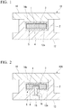
- Fig. 1 is a cross-sectional view obtained by cutting the molding die 10 in a direction perpendicular to a length direction of the molding die.
- thermocompression molding is performed, by the molding die 10, on the molding precursor 5 which is obtained by arranging the prepreg 4 around the core 3 accommodating the wax 1 in the barrier layer 2.
- the fiber reinforced plastic molded body 6 embedding the core 3 is obtainable.
- a method for forming the core 3 is not particularly limited, and for example, a method is exemplified in which the wax 1, which has been molded by a mold in advance, is covered with a film forming a flexible bag 2, both ends of the film are attached or heat-sealed to each other to form the barrier layer 2, and the wax 1 is sealed, thereby obtaining the core 3. Further, a method may be employed in which the wax 1 is put in a shrink tube, both ends of the shrink tube are heat-sealed to each other to form the barrier layer 2, thereby obtaining the core 3. The method using a shrink tube is advantageous in that the barrier layer 2 easily follows the shape of the wax 1 and sealing is easily performed.
- the core 3 may be formed by melting and filling a wax in the barrier layer 2 obtained by blow molding and heat-sealing an opening of the barrier layer 2 to be sealed.
- the core 3 may be formed by applying a liquid rubber serving as the barrier layer 2 to the entire surface around a thermoplastic solid body 1 and drying the liquid rubber.
- the core 3 may be formed by applying a liquid rubber to the entire surface around the thermoplastic solid body 1, then pasting a non-woven fabric serving as a fiber reinforcing material, and further applying a liquid rubber thereto to form the barrier layer 2.
- the prepreg 4 is a composite material for molding including a fiber and a thermosetting resin, and examples thereof include a uni-directional (UD) material in which fibers are arranged in one direction, a cloth material obtained by weaving fibers, and a sheet-shaped prepreg obtained by immersing an uncured thermosetting resin in a fiber reinforcement material such as a sheet molding compound (SMC) in which a non-woven fabric formed by fibers or fibers are chopped.
- UD uni-directional
- SMC sheet molding compound
- the fiber is not particularly limited, but examples thereof include carbon fibers, glass fibers, aramid fibers, silicon carbide fibers, and metallic fibers. Of these, from the viewpoint that a decrease in weight, an increase in strength, and an increase in elastic modulus of the molded body can be achieved, carbon fibers are preferable. Regarding the fiber, one kind may be used alone or two or more kinds thereof may be used in combination.
- thermosetting resin is not particularly limited, but examples thereof include an epoxy resin, a urea resin, a vinyl ester resin, an unsaturated polyester, polyurethane, and a phenolic resin.
- an epoxy resin a urea resin
- a vinyl ester resin an unsaturated polyester
- polyurethane a polyurethane resin
- a phenolic resin a thermosetting resin
- one kind may be used alone or two or more kinds thereof may be used in combination.
- thermosetting resin (hereinafter, referred to as "resin content") with respect to the total mass of the prepreg 4 is preferably 15 to 50% by mass, more preferably 20 to 45% by mass, and further preferably 25 to 40% by mass.
- resin content is 15% by mass or more, adhesiveness between the fiber and the thermosetting resin can be sufficiently ensured, and when the resin content is 50% by mass or less, flame retardancy is further improved.
- the prepreg 4 may include arbitrary components (additives) other than the fiber and the thermosetting resin if necessary.
- arbitrary components include flame retardants (for example, a phosphorus-containing epoxy resin, red phosphorus, a phosphazene compound, a phosphoric acid salt, a phosphoric acid ester, and the like); mold releasing agents such as silicone oil, a wetting dispersant, an antifoaming agent, a defoaming agent, a natural wax, a synthetic wax, a metal salt of a linear fatty acid, an acid amide, an ester, and a paraffin; powders such as crystalline silica, molten silica, calcium silicate, alumina, calcium carbonate, talc, and barium sulfate; inorganic fillers such as glass fibers and carbon fibers; colorants such as carbon black and Bengala; and a silane coupling agent.
- flame retardants for example, a phosphorus-containing epoxy resin, red
- the form of the molding precursor 5 is not particularly limited, but for example, a form in which the entire core 3 is arranged to be embedded by two sheet-shaped prepregs 4 is exemplified.
- the molding die 10 in this example is used to manufacture a square tubular fiber reinforced plastic molded body and includes a lower mold 12 and an upper mold 14.
- a concave part 12a is formed at an upper surface side of the lower mold 12.
- a convex part 14a fitted to the concave part 12a of the lower mold 12 is formed at a lower surface side of the upper mold 14.
- a cavity having a shape complementary to a shape of a target fiber reinforced plastic molded body is formed inside.
- the molding die 10 includes an opening/closing mechanism, and a high-pressure pressing machine may not be employed. That is, in the stage of bringing the lower mold 12 and the upper mold 14 into close contact with each other to clamp the mold, the pressure to be applied to the molding precursor 5 may not be necessarily sufficiently high. Even when the pressure to be applied to the molding precursor 5 in the stage of closing the mold is not sufficient, as described later, the wax is melted at the time of the thermocompression molding to increase the internal pressure of the core, so that a sufficient pressure is applied to the molding precursor 5. Therefore, occurrence of a molding failure can be suppressed and a fiber reinforced plastic molded body with a high dimensional precision is obtainable.
- the following method is exemplified.
- the molding precursor 5 is formed by arranging the prepreg 4 around the core 3
- the molding precursor 5 is preliminarily shaped at room temperature into substantially the same shape as the cavity shape of the molding die 10 to obtain the molding precursor 5 (preform).
- the molding precursor 5 is placed in the concave part 12a of the lower mold 12 of the molding die 10 which has been heated in advance, the molding die 10 is closed to perform the thermocompression molding, and the prepreg 4 is cured.
- the method for the thermocompression molding is not limited to the above-described method.
- the following resin transfer molding (RTM) method may be employed. Specifically, instead of the prepreg, a fiber reinforcement material (fabric) not impregnated with a thermosetting resin is arranged around the core 3 and is placed in the concave part 12a of the lower mold 12, and the molding die 10 is clamped. Next, an uncured thermosetting resin is injected into the molding die 10, the thermosetting resin is impregnated in the fiber reinforcement material, and then the molding die 10 is cured by heating, thereby obtaining the molded body 6.
- RTM resin transfer molding
- thermocompression molding under the condition that a relation between a melting point Tm (°C) and an average molding temperature Tf (°C) of the thermoplastic solid body typified by a wax or the like satisfies Tf - 60 ⁇ Tm ⁇ Tf.
- Tm melting point
- Tf average molding temperature
- heat of the molding die 10 is transferred to the prepreg 4 and is further transferred also to the wax 1 through the barrier layer 2, so that at least a part of the wax 1 is melted.
- the melting point Tm indicates the lowest melting point among melting points of the plurality of components.
- thermocompression molding under the condition that, in a case where a melting point of the thermoplastic solid body 1 is designated as Tm (°C), a temperature of heat molding is designated as Tf (°C), and a melting point of a material forming the barrier layer 2 is designated as Tb (°C), a relation thereof satisfies Tm ⁇ Tf ⁇ Tb.
- Tm melting point of the thermoplastic solid body 1
- Tf temperature of heat molding
- Tb melting point of a material forming the barrier layer 2
- heat of the molding die 10 is transferred to the prepreg 4 and is further transferred also to the thermoplastic solid body 1 through the barrier layer 2, so that at least a part of the thermoplastic solid body 1 is melted.
- the melting point Tb (°C) indicates the lowest melting point among melting points of the plurality of components.
- the internal pressure of the core 3 increases at the time of the thermocompression molding. Further, since the wax 1 in a melted state in the barrier layer 2 flows, the internal pressure becomes uniform at the entire core 3.
- the pressure of the core 3 becomes uniform, in the thermocompression molding, the pressure is uniformly applied to the prepreg 4 also in a direction other than the vertical direction in which the lower mold 12 and the upper mold 14 of the molding die 10 are closed.
- the wax 1 is accommodated in the barrier layer 2 in the core 3, the melted wax 1 leaking outside the prepreg 4 is suppressed. Further, since the barrier layer 2 has flexibility and can be stretched, distortion of the outer shape of the core according to the flowing of the wax 1 is acceptable. Therefore, when the internal pressure increases by expansion of the wax 1, the core 3 is expanded. According to this, even if an air gap is formed between the core 3 and the prepreg 4 arranged around the core, the air gap is buried by the distortion of the core 3. Further, even when an air gap is formed between a molding surface and the prepreg 4 in a corner portion inside the molding die 10, the air gap is buried by the prepreg 4 being pressed against the molding surface according to the distortion of the core 3.
- the prepreg 4 is in close contact with the core 3 on the molding surface of the molding die 10 with no gap, occurrence of a molding failure is suppressed, particularly, bending, wrinkles, voids, or the like of a rising surface hardly occur, and a molded body having a predetermined thickness and high dimensional precision is obtainable. Also in a case where a fiber reinforced plastic molded body having right angle corner portions is manufactured, a prepreg is sufficiently filled in corner portions of the molding die, and the corner portions have an right angle following the molding surface of the molding die with high precision.
- the air gap formed between the prepreg 4 and the core 3 When the air gap formed between the prepreg 4 and the core 3 is buried, the air gap is crushed by pressure from the core 3 or air constituting the air gap passes through the prepreg 4 and released from the gap of the molding die 10 into the atmosphere. When the air passes through the prepreg 4, holes are generated in the prepreg 4, but the holes are naturally blocked since the prepreg 4 has flowability.
- thermocompression molding only a part of the wax 1 may be melted or the entire wax 1 may be melted.
- the wax 1 is melted by heat transfer from the molding die 10, but since the wax 1 has a low thermal conductivity, particularly in a case where the volume of the core 3 is large and the molding time is short, only the surface layer of the wax 1 is melted.
- thermocompression molding In order to improve a molding cycle in the thermocompression molding, it is necessary to efficiently heat the prepreg. As heat is consumed for melting the wax of the core, a time for increasing the temperature of the prepreg is further required. In the view of improvement in the molding cycle, it is preferable to melt only the surface layer of the wax in the thermocompression molding. Further, in the case of melting only the surface layer of the wax, even if the melted wax leaks out from the barrier layer, the melted amount is small and the wax leaking out from the molding die is rapidly cooled and solidified, so that an adverse effect can be minimized.
- the relation between the melting point Tm and the average molding temperature Tf of the thermoplastic solid body typified by a wax or the like is set to preferably Tf - 60 ⁇ Tm ⁇ Tf, more preferably Tf - 50 ⁇ Tm ⁇ Tf - 10, and further preferably Tf - 40 ⁇ Tm ⁇ Tf - 20.
- Tf - 60 ⁇ Tm ⁇ Tf more preferably Tf - 50 ⁇ Tm ⁇ Tf - 10
- Tf - 40 ⁇ Tm ⁇ Tf - 20 is set to preferably Tf - 60 ⁇ Tm ⁇ Tf, more preferably Tf - 50 ⁇ Tm ⁇ Tf - 10, and further preferably Tf - 40 ⁇ Tm ⁇ Tf - 20.
- the thermoplastic solid body is hardly softened and the shape of the core is stable before the thermocompression molding, so that a degradation in appearance of the fiber reinforced plastic molded body caused by wrinkles occurring in the prepreg before the thermocompression molding can be suppressed. Further, the thermoplastic solid body is hardly softened at room temperature and the handleability of the core is improved. In addition, even when the thermoplastic solid body leaks out, the thermoplastic solid body is easily solidified and influence of the leakage thereof is small.
- the melting point Tm is set to preferably Tf or lower, more preferably (Tf - 10) or lower, and further preferably (Tf - 20) or lower, the thermoplastic solid body is melted at the time of the thermocompression molding so that the internal pressure of the core is likely to increase, and a molding failure is easy to suppress.
- the average molding temperature Tf means an average value of the mold temperatures from starting of molding to termination of molding.
- the average molding temperature Tf at the time of the thermocompression molding depends on a curing temperature of the thermosetting resin of the prepreg and is preferably 110 to 160°C and more preferably 120 to 150°C.
- the melting point Tm of the thermoplastic solid body typified by a wax or the like is preferably 80 to 140°C, more preferably 90 to 130°C, and further preferably 100 to 120°C.
- the melting point Tb of the barrier layer is preferably 110°C or higher and more preferably 150°C or higher.
- the relation between the melting point Tb and the average molding temperature Tf of the barrier layer is set to preferably Tf + 10 ⁇ Tb ⁇ Tf + 60, more preferably Tf + 15 ⁇ Tb ⁇ Tf + 60, and further preferably Tf + 20 ⁇ Tb ⁇ Tf + 60.
- Tf + 10 ⁇ Tb ⁇ Tf + 60 more preferably Tf + 15 ⁇ Tb ⁇ Tf + 60
- Tf + 20 ⁇ Tb ⁇ Tf + 60 is set to preferably Tf + 10 ⁇ Tb ⁇ Tf + 60, more preferably Tf + 15 ⁇ Tb ⁇ Tf + 60, and further preferably Tf + 20 ⁇ Tb ⁇ Tf + 60.
- the core may be pressed in the molding die. According to this, even in the case of manufacturing a large-sized fiber reinforced plastic, since the internal pressure of the core is easy to sufficiently increase, adjustment such as decreasing of the internal pressure of the core can be performed in a case where the pressure excessively increases, and a molding failure can be stably suppressed.
- the pressing of the core is preferably performed by a rod provided in the molding die.
- a rod provided in the molding die.
- a piston rod is preferably used.
- a molding die 10A illustrated in Fig. 2 in which a piston rod 16 protruding into the concave part 12a is provided at the lower mold 12 can be used.
- the same components in Fig. 2 as those in Fig. 1 are denoted by the same reference numerals and descriptions thereof are omitted.
- the piston rod 16 and a cylinder 18 are provided in the lower mold 12 of the molding die 10A.
- the piston rod 16 is configured to project or retract in the cavity at the time of mold closing.
- the core 3 is partially pressed along with the prepreg 4. Since the wax 1 in the core 3 is melted, the pressing force is efficiently transferred to the entire core 3, and thus the pressure becomes uniform also in a portion away from a portion, which is pressed by the piston rod 16, of the core 3. The internal pressure of the core 3 is further increased by the pressing, and the melted wax 1 flows to cause the distortion of the core 3, so that the core 3 and the prepreg 4 are brought into closer contact with each other. Further, the prepreg 4 reaches every corner of the molding die 10 and is sufficiently pressed against the molding surface, so that an air gap is eliminated.
- the pressure can be controlled by bringing the piston rod 16 down.
- an embodiment of the pressing the core is not limited to the embodiment illustrated in Fig. 2 .
- a plurality of portions in the core may be pressed using a molding die provided with a plurality of rods.
- a pressing hole is formed in the prepreg arranged around the core and the core may be directly pressed by a rod through the hole.
- a portion at which the prepreg is not present around the core may be pressed by a rod.
- the wax 1 is discharged from the fiber reinforced plastic molded body 6 obtained after the molding step.
- the method for discharging the wax it is preferable to use a method for discharging the wax 1 outside the fiber reinforced plastic molded body 6 after the thermocompression molding at a temperature Tw that is equal to or lower than the heat distortion temperature Td (°C) of the fiber reinforced plastic molded body 6 and equal to or higher than the melting point Tm (°C) of the wax 1.
- this temperature Tw (°C) is more preferably within a range of Tm + 10 ⁇ Tw ⁇ Td - 10 and further preferably within a range of Tm + 20 ⁇ Tw ⁇ Td - 20.
- the wax 1 can be efficiently discharged while the thermal distortion of the fiber reinforced plastic molded body 6 is prevented. Further, in a case where the fiber reinforced plastic molded body 6 is configured by a plurality of components each having a different heat distortion temperature, the heat distortion temperature Td (°C) indicates the lowest temperature among heat distortion temperatures of the plurality of components.
- a discharge hole 7 is formed in the fiber reinforced plastic molded body 6, and then heating is performed at a temperature that is equal to or lower than the heat distortion temperature of the fiber reinforced plastic molded body 6 and equal to or higher than the melting point of the wax 1.
- the melted wax 1 is discharged from the discharge hole 7 outside the fiber reinforced plastic molded body 6. By melting the wax 1, even when the discharge hole 7 has a small diameter, the wax 1 can be discharged.
- the method for forming the discharge hole 7 in the fiber reinforced plastic molded body 6 is not particularly limited, but examples thereof include drill processing and hole saw processing.
- the method for heating the core 3 and the fiber reinforced plastic molded body 6 is not particularly limited, but examples thereof include oven heating and infrared heating.
- the hole remaining in the fiber reinforced plastic molded body may be used as a wax discharge hole.
- a discharge hole for discharging the wax may be formed.
- an air blowing hole may be further provided in the fiber reinforced plastic molded body 6 in addition to the discharge hole 7 in the range that there is no adverse effect on product quality, and the discharging of the wax 1 from the discharge hole 7 by performing air blowing through the air blowing hole may be promoted.
- a string is prepared to be present in the core in advance, and the discharging of the wax by pulling the string at the time of discharging the wax can also be promoted.
- the barrier layer 2 in the fiber reinforced plastic molded body 6 may be taken out if necessary, or may remain in the fiber reinforced plastic molded body 6 without change.
- thermocompression molding is performed using the thermoplastic solid body typified by a wax or the like as the core. Since the internal pressure of the core can be sufficiently increased by melting at least a part of the thermoplastic solid body at the time of the compression molding, proceeding of the prepreg being cured in a state in which there is an air gap between the core and the prepreg or between the prepreg and the molding surface of the molding die can be suppressed. Further, since the thermoplastic solid body is hardly softened and the shape of the core is stable before the thermocompression molding, wrinkles less occur in the prepreg before the thermocompression molding and occurrence of wrinkles also in the fiber reinforced plastic molded body can be suppressed. In this way, even in the case of a large-sized fiber reinforced plastic molded body, occurrence of a molding failure can be suppressed, and a fiber reinforced plastic molded body with excellent appearance can be efficiently and economically manufactured.
- the dimension of the fiber reinforced plastic molded body is not particularly limited, but the method for manufacturing a fiber reinforced plastic molded body of the invention can be particularly suitably employed, for example, in manufacturing a molded body having a core volume of 100 cm3 or more.
- the method for manufacturing a fiber reinforced plastic molded body of the invention is not limited to the above-described method.
- the above-described method is a method for manufacturing a square tubular fiber reinforced plastic molded body, but may be a method for manufacturing a fiber reinforced plastic molded body having a U-shaped cross-section.
- a molding precursor in which a part of a core is exposed and other parts are covered by a prepreg is formed, and thermocompression molding is performed in a state in which a part of the core is in contact with a molding surface of a molding die.
- thermoplastic solid body typified by a wax or the like, it is not necessary to provide a discharge hole in the fiber reinforced plastic molded body.
- the internal pressure of the core in the thermocompression molding was measured by a piezoelectric pressure sensor. Further, the surface temperature and the center temperature of the wax in the core were measured by a thermocouple. Incidentally, in the measurement, the molding precursor 5 was placed to the lower mold 12 after 60 seconds from the measurement start and then mold clamping was performed, and then after 360 seconds (molding time of 5 minutes), mold opening was performed.
- the appearance of the fiber reinforced plastic molded body obtained in each example was checked by visual inspection and evaluated by the following evaluation criteria.
- a synthetic wax (product name "File-A-Wax Green,” manufactured by Freeman Manufacturing & Supply Company, melting point Tm: 117°C, density: 0.9 g/cm 3 ) was used as the wax 1 and put in a shrink tube made of polyolefin (thickness: 15 ⁇ m; melting point Tb: 145°C), and both ends of the shrink tube was heat-sealed to form the barrier layer 2 formed by a flexible bag, thereby manufacturing the core 3.
- a prepreg manufactured by Mitsubishi Rayon Co., Ltd., product name "TR3110 360GMP"; resin content: 40% by mass
- the prepreg 4 two prepregs were arranged to cover the circumference of the entire core 3, and then the obtained product was preliminarily shaped at room temperature into substantially the same shape as the cavity shape of the molding die 10 to obtain the molding precursor 5 (preform).
- the molding precursor 5 was disposed in the concave part 12a of the lower mold 12 of the molding die 10 to close the molding die 10, and the thermocompression molding was performed while the average molding temperature from the mold closing to the mold opening was set to 140°C and the molding time was set to 5 minutes, thereby manufacturing the fiber reinforced plastic molded body 6 embedding the core 3.
- the results obtained by measuring the internal pressure of the core 3 and the surface temperature and the center temperature of the wax at the time of the thermocompression molding are shown in Fig. 4 .
- the discharge hole 7 (diameter: 10 mm) for discharging the wax was formed in the fiber reinforced plastic molded body 6 by drill processing.
- the core 3 and the fiber reinforced plastic molded body 6 were heated to 130°C by oven heating so that the wax 1 was melted and discharged from the discharge hole 7, thereby obtaining the square tubular fiber reinforced plastic molded body 6 having a size of 73 mm ⁇ 37 mm ⁇ 26 mm.
- a square tubular fiber reinforced plastic molded body was obtained in the same manner as in Example 1, except that hollow glass beads (density: 0.2 g/cm 3 ) were used as the filler and a mixture in which the proportion of the hollow glass beads with respect to the total mass of the wax and the hollow glass beads is set to 30% by volume was used as the core.
- a square tubular fiber reinforced plastic molded body was obtained in the same manner as in Example 1, except that a polypropylene wax (melting point Tm: 165°C) was used as the wax 1.
- a square tubular fiber reinforced plastic molded body was obtained in the same manner as in Example 1, except that a synthetic wax (product name "TOYO UTILITY WAX,” manufactured by TOYOKAGAKU KENKYUSHO CO., LTD., melting point Tm: 72°C) was used as the wax 1.
- a synthetic wax product name "TOYO UTILITY WAX,” manufactured by TOYOKAGAKU KENKYUSHO CO., LTD., melting point Tm: 72°C
- a square tubular fiber reinforced resin molded body was obtained in the same manner as in Example 1, except that the barrier layer 2 (thickness: 40 ⁇ m; melting point Tb: 165°C) was formed using a shrink tube made of polypropylene.
- a square tubular fiber reinforced resin molded body was obtained in the same manner as in Example 1, except that the barrier layer 2 (thickness: 25 ⁇ m; melting point Tb: 200°C) was formed using a shrink tube made of polyvinyl chloride.
- a square tubular fiber reinforced resin molded body was obtained in the same manner as in Example 1, except that the barrier layer 2 (thickness: 0.1 mm) formed by a coating material was formed by applying an acrylic liquid rubber (manufactured by YUTAKA MAKE Co., Ltd., BE-1) to the wax and drying the acrylic liquid rubber, instead of a shrink tube.
- the barrier layer 2 thickness: 0.1 mm
- an acrylic liquid rubber manufactured by YUTAKA MAKE Co., Ltd., BE-1
- a square tubular fiber reinforced resin molded body was obtained in the same manner as in Example 7, except that the barrier layer 2 (thickness: 0.2 mm) was formed by applying and drying a silicone-based liquid rubber (manufactured by Shin-Etsu Chemical Co., Ltd., KE-66).
- a square tubular fiber reinforced resin molded body was obtained in the same manner as in Example 1, except that the barrier layer 2 (thickness: 0.2 mm; melting point Tb: 115°C) formed by a coating material was formed by applying an acrylic liquid rubber to the wax and drying the acrylic liquid rubber, then pasting a polyamide-based non-woven fabric (Kureha Ltd., LNS0015) thereto, and further applying a liquid rubber.
- the barrier layer 2 thickness: 0.2 mm; melting point Tb: 115°C
- a coating material was formed by applying an acrylic liquid rubber to the wax and drying the acrylic liquid rubber, then pasting a polyamide-based non-woven fabric (Kureha Ltd., LNS0015) thereto, and further applying a liquid rubber.
- a square tubular fiber reinforced resin molded body was obtained in the same manner as in Example 9, except that the barrier layer 2 (thickness: 0.2 mm; melting point Tb: 150°C) was formed using a polyester-based non-woven fabric (Kureha Ltd., G5025) instead of a polyamide-based non-woven fabric.
- Example 2 in which a further decrease in weight of the molding precursor is achieved and Examples 9 and 10 in which the strength of the barrier layer is improved were particularly excellent in workability.
- Example 7 using a coating material as the barrier layer, a fiber reinforced plastic molded body with quite excellent appearance was obtainable. Furthermore, as shown in Fig. 4 , in Example 1, the surface temperature of the wax in the thermocompression molding was higher than the melting point Tm and the internal pressure of the core increased by the surface layer being melted by heating.
Landscapes
- Engineering & Computer Science (AREA)
- Mechanical Engineering (AREA)
- Chemical & Material Sciences (AREA)
- Composite Materials (AREA)
- Casting Or Compression Moulding Of Plastics Or The Like (AREA)
- Moulding By Coating Moulds (AREA)
- Moulds For Moulding Plastics Or The Like (AREA)
Abstract
Description
- The present invention relates to a method for manufacturing a fiber reinforced plastic molded body.
- The present application claims the priority of Japanese Patent Application No.
2016-213228 filed on October 31, 2016 - Fiber reinforced plastic (FRP) molded bodies having a hollow shape, a U shape, and the like have been widely used in large molded bodies such as bodies and wings of aircrafts to small molded bodies such as bicycle frames, tennis rackets, fishing rods, and golf shafts.
- As a method for manufacturing fiber reinforced plastic molded bodies having a hollow shape, a U shape, and the like, a method has been known in which a prepreg obtained by immersing a resin in a fiber (filament) is arranged around a core, molding is performed, and then the core is removed.
- For example, a method has been proposed in which FRP materials are staked on a molding die made of a wax, and the molding die made of a wax is melted and removed after molding and curing (Patent Document 1).
- Further, a method has been proposed which includes a step of preparing a core using a synthetic wax, a step of pasting a prepreg to the entire outer surface of the core and forming a wax discharge hole in the pasted prepreg, and a step of discharging the melted synthetic wax from the wax discharge hole while the core and the prepreg are heated to thermally cure the prepreg to thereby obtain a fiber reinforced plastic molded body (Patent Document 2).
- Further, a method has been proposed which includes a step of arranging a prepreg including a fiber reinforcement material and a thermosetting resin around a solid mandrel material, a step of curing the prepreg to form a fiber reinforced plastic molded body, a step of melting the mandrel material at a temperature lower than a glass transition temperature of the fiber reinforced plastic molded body to obtain a liquid material, a step of discharging the liquid material, and a step of cooling the fiber reinforced plastic molded body (Patent Document 3).
- Further, a method has been proposed in which a liquid is sealed in a mandrel formed by a deformable hollow body, a continuous resin-impregnated fiber bundle is wound around the mandrel in a netlike manner, and then the resin is cured by increasing the internal pressure of the mandrel while being restricted by a heated molding die (Patent Document 4).
-
- Patent Document 1:
JP 4-7127 A - Patent Document 2:
JP 2007-307853 A - Patent Document 3:
JP 2014-534914 W - Patent Document 4:
JP 62-5842 A - In the method of
Patent Document 1, since molding is performed by curing at normal temperature, the curing temperature becomes long, which results in a decrease in production efficiency. Further, since hand lay-up is performed directly to a wax surface layer, after the wax is melted and removed, there is a possibility that the wax remains between filaments. - In the method of
Patent Document 2, since the core is melted and removed while the prepreg is cured, the number of processes is small. However, a part of the core is easily removed before the curing of the prepreg sufficiently proceeds, and particularly in the case of a large-sized fiber reinforced plastic molded body, the shape of the molded body is not stable and an air gap such as a void may occur in the molded body. Therefore, it is difficult to efficiently obtain a high-quality fiber reinforced plastic molded body, which is disadvantageous in terms of economical aspect. - Further, in the method of
Patent Document 3, particularly in a case where a pressure is likely to be applied in one direction at the time of closing a mold such as a molding die provided with an upper mold and a lower mold, a pressure is hardly applied uniformly to the mandrel material and a molding failure such as a void of a rising surface (surface extending in an upper direction from a bottom portion of a mold cavity) or chipping of the corner portion easily occurs. - Further, in the method of
Patent Document 4, since gas such as air is sealed in the mandrel, the molding pressure is easily decreased, and a molding failure easily occurs at the rising surface or the corner portion. - An object of the invention is to provide a method for manufacturing a fiber reinforced plastic molded body by which it is possible to efficiently and economically manufacture a fiber reinforced plastic molded body with excellent appearance which has a high degree of freedom for the shape of molding and in which occurrence of a molding failure can be suppressed even in the case of a large-sized fiber reinforced plastic molded body.
- The invention has the following configurations.
- [1] A method for manufacturing a fiber reinforced plastic molded body, the method including performing thermocompression molding, by using a molding die, on a molding precursor which is obtained by arranging a prepreg including a thermosetting resin and a fiber around a thermoplastic solid body.
- [2] The method described in [1], in which a density of the thermoplastic solid body is 8 g/cm3 or less.
- [3] The method described in [1] or [2], in which the thermoplastic solid body is a wax.
- [4] The method described in any one of [1] to [3], in which a filler having a lower density than that of the thermoplastic solid body is further accommodated in the thermoplastic solid body.
- [5] The method described in [4], in which a proportion of the filler with respect to 100% by volume of the total of the thermoplastic solid body and the filler is set to 5 to 70% by volume.
- [6] The method described in any one of [1] to [5], in which the molding precursor includes a barrier layer formed between the thermoplastic and the prepreg.
- [7] The method described in [6], in which the barrier layer is a flexible bag or a coating material.
- [8] The method described in [6] or [7], in which the barrier layer includes a fiber reinforcing material.
- [9] The method described in any one of [1] to [8], in which the thermocompression molding is performed under the condition that a relation between a melting point Tm (°C) and an average molding temperature Tf (°C) of the thermoplastic solid body satisfies Tf - 60 ≤ Tm ≤ Tf.
- [10] The method described in any one of [6] to [9], in which the thermocompression molding is performed under the condition that a relation between a melting point Tm (°C) and an average molding temperature Tf (°C) of the thermoplastic solid body and a melting point Tb (°C) of a material forming the barrier layer satisfies Tm ≤ Tf < Tb.
- [11] The method described in any one of [1] to [10], in which the thermocompression molding is performed in a state in which at least a part of a surface layer portion of the thermoplastic solid body is melted.
- [12] The method described in any one of [1] to [11], in which the thermoplastic solid body is pressed in the molding die at the time of the thermocompression molding.
- [13] The method described in [12], in which the pressing of the thermoplastic solid body is performed by a rod provided in the molding die.
- [14] The method described in any one of [1] to [13], in which the thermoplastic solid body is removed from the obtained fiber reinforced plastic molded body after the thermocompression molding.
- [15] The method described in [14], in which the thermoplastic solid body is discharged outside the fiber reinforced plastic molded body at a temperature that is equal to or lower than a heat distortion temperature of the fiber reinforced plastic molded body and equal to or higher than the melting point Tm (°C) of the thermoplastic solid body.
- According to the method for manufacturing a fiber reinforced plastic molded body of the invention, it is possible to efficiently and economically manufacture a fiber reinforced plastic molded body with excellent appearance which has a high degree of freedom for the shape of molding and in which occurrence of a molding failure can be suppressed even in the case of a large-sized fiber reinforced plastic molded body.
-
-
Fig. 1 is a schematic cross-sectional view illustrating an example of thermocompression molding in a method for manufacturing a fiber reinforced plastic molded body of the invention; -
Fig. 2 is a schematic cross-sectional view illustrating an example of thermocompression molding in the method for manufacturing a fiber reinforced plastic molded body of the invention; -
Fig. 3A is a schematic cross-sectional view illustrating a state in which a fiber reinforced plastic molded body embedding a wax as a thermoplastic solid body is obtained in the method for manufacturing a fiber reinforced plastic molded body of the invention; -
Fig. 3B is a schematic cross-sectional view illustrating a state in which a discharge port for discharging the wax is formed in the fiber reinforced plastic molded body obtained inFig. 3A ; -
Fig. 3C is a schematic cross-sectional view illustrating a state after the wax is discharged through the discharge port formed inFig. 3B ; and -
Fig. 4 is a graph showing results obtained by measuring an internal pressure of a core and a surface temperature and a center temperature of a wax in thermocompression molding of Example 1. - A method for manufacturing a fiber reinforced plastic molded body of the invention is a method for obtaining a fiber reinforced plastic molded body by performing thermocompression molding, by using a molding die, on a molding precursor which is obtained by arranging a prepreg including a thermosetting resin and a fiber around a thermoplastic solid body.
- The thermoplastic solid body used in the invention has a function as a core used when a fiber reinforced plastic molded body having a hollow shape, a U shape, or the like is manufactured, and is configured by a material which does not show plasticity at an atmospheric temperature before hot-press molding typified by a normal temperature (20°C) but has a property that the material is softened or melted at the time of thermocompression molding and is freely distorted.
- This thermoplastic solid body can be easily removed from the obtained molded body by setting the temperature, for example, to a temperature that is equal to or lower than a heat distortion temperature of the molded body and equal to or higher than a melting point of the thermoplastic solid body after the thermocompression molding.
- This thermoplastic solid body is not particularly limited as long as it is configured by the above-described material, but a material having a density of 8 g/cm3 or less is preferable. The reason for this is that by setting the density of the thermoplastic solid body to 8 g/cm3 or less, the molding precursor can be decreased in weight, and particularly at the time of manufacturing a large-sized fiber reinforced plastic molded body, there is a tendency that workability becomes favorable and the distortion of the molding precursor due to its own weight can be prevented. The density is more preferably 2 g/cm3 or less and further preferably 1 g/cm3 or less. The lower limit is not particularly limited, but from the viewpoint of ensuring the minimum strength and workability, the density is preferably 0.6 g/cm3 or more.
- Examples of the material constituting the thermoplastic solid body may include a thermoplastic resin such as polyolefin, polyvinyl chloride, polystyrene, polyvinyl acetate, polyurethane, or an acrylic resin; a low melting point metal such as tin or indium; a fusible alloy such as solder, Wood's alloy, Rose's alloy, Lipowitz' alloy, or Newton alloy; and low melting point glass, but from the viewpoints that a melting point equal to or lower than a molding temperature of the prepreg can be obtained, processing to have a desired shape is easy, the density is low, and the molding precursor can be decreased in weight, it is preferable to use a wax.
- As the wax, a natural wax such as paraffin wax or a synthetic wax such as Fischer-Tropsch wax or polyethylene wax can be appropriately selected and used. These may be used alone or in combination of two or more kinds thereof, and when a wax for lost-wax casting is used, there is a tendency that the wax is easy to remove after the molding of the fiber reinforced plastic molded body of the invention, which is preferable.
- Further, in the thermoplastic solid body used in the invention, it is preferable to further accommodate a filler having a lower density than that of the thermoplastic solid body.
- For example, by the wax containing a filler having a lower density than that of the wax, the mass of the thermoplastic solid body can be further decreased, so that handleability in the case of manufacturing a large-sized fiber reinforced plastic molded body is further excellent.
- As the filler, any filler can be appropriately selected and used as long as it has a lower density than that of the thermoplastic solid body, but particularly, from the viewpoints that a thermal conductivity is low and the molding cycle is improved by efficiently increasing the temperature of the prepreg since the thermal energy in molding is difficult to excessively consume by the thermoplastic solid body, hollow glass beads and hollow metal balls are preferable.
- Regarding the filler, one kind thereof may be used alone or two or more kinds thereof may be used in combination.
- In the case of using a filler in the thermoplastic solid body, a proportion of the filler with respect to 100% by volume of the total of the thermoplastic solid body and the filler is preferably 5 to 70% by volume, more preferably 10 to 60% by volume, and further preferably 20 to 50% by volume. By setting the proportion of the filler to preferably 5% by volume or more, more preferably 10% by volume or more, and further preferably 20% by volume or more, the handleability of the thermoplastic solid body is further excellent, a large-sized fiber reinforced plastic molded body is easily manufactured, and the molding cycle is improved. By setting the proportion of the filler to preferably 70% by volume or less, more preferably 60% by volume or less, and further preferably 50% by volume or less, flowability is maintained by the thermoplastic solid body being melted, the internal pressure of the molding precursor is increased, and a sufficient pressure is easy to uniformly apply to the entire prepreg, so that a molding failure is easy to suppress.
- Further, in the invention, it is preferable to use a molding precursor in which a barrier layer is formed around the thermoplastic solid body and a prepreg including a thermosetting resin and a fiber is arranged around the barrier layer. According to this, a melted product of the thermoplastic solid body is prevented from leaking out from the surface of the molding precursor during the thermocompression molding and the appearance and the shape of a molded article can be maintained to be favorable.
- Examples of the barrier layer include a flexible bag and a coating material, and the barrier layer can be formed on the surface of the prepreg and/or the surface of the thermoplastic solid body; however, the barrier layer is preferably formed on the surface of the thermoplastic solid body since there is a tendency that moldability to a complicate shape or the appearance of the molded article becomes favorable.
- The thickness of the barrier layer may be appropriately set within a range that the barrier layer has flexibility and breakage affecting the molded body during the thermocompression molding does not occur, and the thickness thereof may be set, for example, to 1 mm or less. The lower limit of the thickness of the barrier layer is not particularly limited, but from the viewpoint of ensuring the minimum strength, the thickness thereof is preferably 0.01 mm or more.
- As the flexible bag, any bag having flexibility may be used, and examples thereof include bags formed by a nylon film, a polypropylene film, a polyethylene film, a fluororesin film, silicon rubber, and the like.
- Further, as the coating material, any material fixed around the thermoplastic solid body and having flexibility may be used, and examples thereof include liquid rubbers containing an acrylic component or silicone as a main component. Furthermore, those which are melted at the time of the thermocompression molding to form a film around the thermoplastic solid body may be used. For example, nylon paper is arranged around the thermoplastic solid body and is caused to be melted at the time of the thermocompression molding, so that the barrier layer can be formed.
Moreover, a liquid rubber and this paper can also be used in combination. - Particularly, in the case of using a coating material as the barrier layer, seams of the barrier layer can be eliminated and the seams are not transferred to a molded article to be obtained in the thermocompression molding, so that the appearance of the molded article can be made further excellent.
- In the invention, it is preferable that a mold releasing process such as application of a mold releasing agent to the outer surface of the barrier layer formed around the thermoplastic solid body is performed or the barrier layer is doubled. According to this, the barrier layer attached with the thermoplastic solid body can be easily removed from the fiber reinforced resin molded body after the thermocompression molding.
- Further, the barrier layer may include a fiber reinforcing material. Particularly, in a case where the barrier layer is configured by a coating material, when one obtained by stacking a coating material layer and a fiber reinforcing material layer is used as the barrier layer, the strength of the barrier layer is improved so that the breakage of the barrier layer at the time of the thermocompression molding can be prevented. The coating material layer and the fiber reinforcing material layer may be stacked in many layers and the stacking order thereof can be appropriately selected.
- Herein, examples of a fiber which can be used in the fiber reinforcing material include polyester fibers, polyolefin fibers, acrylic fibers, glass fibers, aramid fibers, and vinylon fibers. These can be appropriately selected, but from the viewpoint of lightweight and favorable handleability, aramid fibers are preferable.
- The form of the fiber reinforcing material which can be used in the barrier layer is not particularly limited, but examples thereof may include woven fabrics such as a non-crimped fabric and a cord fabric; paper or non-woven fabrics, and random material sheets of discontinuous fibers.
- Hereinafter, an example of the method for manufacturing a fiber reinforced plastic molded body of the invention will be described in detail with reference to the drawings. Incidentally, the dimension and the like in the respective drawings are merely examples, and the invention is not necessarily limited to examples illustrated in the respective drawings and can be modified as appropriate without departing from the gist of the invention.
- The method for manufacturing a fiber reinforced plastic molded body of the present embodiment includes the following molding step, and can further include the following discharging step of a thermoplastic solid body typified by a wax or the like.
- Molding step: As illustrated in
Fig. 1 , thermocompression molding is performed on amolding precursor 5 which is obtained by arranging aprepreg 4 around acore 3 accommodating awax 1 in abarrier layer 2 while at least a part of thewax 1 is melted by amolding die 10. - Discharging step of thermoplastic solid body: As illustrated in
Figs. 3A to 3C , thewax 1 is discharged from a fiber reinforced plastic moldedbody 6 obtained after the molding step. - This example corresponds to a case where a square tubular fiber reinforced plastic molded body to be used in a pipe or the like is manufactured.
-
Fig. 1 is a cross-sectional view obtained by cutting the molding die 10 in a direction perpendicular to a length direction of the molding die. - In the molding step of the present embodiment, first, as illustrated in
Fig. 1 , thermocompression molding is performed, by the molding die 10, on themolding precursor 5 which is obtained by arranging theprepreg 4 around thecore 3 accommodating thewax 1 in thebarrier layer 2. According to this, as illustrated inFig. 3A , the fiber reinforced plastic moldedbody 6 embedding thecore 3 is obtainable. - A method for forming the
core 3 is not particularly limited, and for example, a method is exemplified in which thewax 1, which has been molded by a mold in advance, is covered with a film forming aflexible bag 2, both ends of the film are attached or heat-sealed to each other to form thebarrier layer 2, and thewax 1 is sealed, thereby obtaining thecore 3. Further, a method may be employed in which thewax 1 is put in a shrink tube, both ends of the shrink tube are heat-sealed to each other to form thebarrier layer 2, thereby obtaining thecore 3. The method using a shrink tube is advantageous in that thebarrier layer 2 easily follows the shape of thewax 1 and sealing is easily performed. In addition, thecore 3 may be formed by melting and filling a wax in thebarrier layer 2 obtained by blow molding and heat-sealing an opening of thebarrier layer 2 to be sealed. - Alternatively, the
core 3 may be formed by applying a liquid rubber serving as thebarrier layer 2 to the entire surface around a thermoplasticsolid body 1 and drying the liquid rubber. As further another method, thecore 3 may be formed by applying a liquid rubber to the entire surface around the thermoplasticsolid body 1, then pasting a non-woven fabric serving as a fiber reinforcing material, and further applying a liquid rubber thereto to form thebarrier layer 2. - The
prepreg 4 is a composite material for molding including a fiber and a thermosetting resin, and examples thereof include a uni-directional (UD) material in which fibers are arranged in one direction, a cloth material obtained by weaving fibers, and a sheet-shaped prepreg obtained by immersing an uncured thermosetting resin in a fiber reinforcement material such as a sheet molding compound (SMC) in which a non-woven fabric formed by fibers or fibers are chopped. - The fiber is not particularly limited, but examples thereof include carbon fibers, glass fibers, aramid fibers, silicon carbide fibers, and metallic fibers. Of these, from the viewpoint that a decrease in weight, an increase in strength, and an increase in elastic modulus of the molded body can be achieved, carbon fibers are preferable. Regarding the fiber, one kind may be used alone or two or more kinds thereof may be used in combination.
- The thermosetting resin is not particularly limited, but examples thereof include an epoxy resin, a urea resin, a vinyl ester resin, an unsaturated polyester, polyurethane, and a phenolic resin. Regarding the thermosetting resin, one kind may be used alone or two or more kinds thereof may be used in combination.
- Further, the content of the thermosetting resin (hereinafter, referred to as "resin content") with respect to the total mass of the
prepreg 4 is preferably 15 to 50% by mass, more preferably 20 to 45% by mass, and further preferably 25 to 40% by mass. When the resin content is 15% by mass or more, adhesiveness between the fiber and the thermosetting resin can be sufficiently ensured, and when the resin content is 50% by mass or less, flame retardancy is further improved. - The
prepreg 4 may include arbitrary components (additives) other than the fiber and the thermosetting resin if necessary. Examples of such arbitrary components include flame retardants (for example, a phosphorus-containing epoxy resin, red phosphorus, a phosphazene compound, a phosphoric acid salt, a phosphoric acid ester, and the like); mold releasing agents such as silicone oil, a wetting dispersant, an antifoaming agent, a defoaming agent, a natural wax, a synthetic wax, a metal salt of a linear fatty acid, an acid amide, an ester, and a paraffin; powders such as crystalline silica, molten silica, calcium silicate, alumina, calcium carbonate, talc, and barium sulfate; inorganic fillers such as glass fibers and carbon fibers; colorants such as carbon black and Bengala; and a silane coupling agent. Further, the content of the arbitrary component with respect to the total mass of theprepreg 4 is preferably 0 to 25% by mass, more preferably 1 to 20% by mass, and further preferably 1 to 15% by mass. - The form of the
molding precursor 5 is not particularly limited, but for example, a form in which theentire core 3 is arranged to be embedded by two sheet-shapedprepregs 4 is exemplified. - The molding die 10 in this example is used to manufacture a square tubular fiber reinforced plastic molded body and includes a
lower mold 12 and anupper mold 14. Aconcave part 12a is formed at an upper surface side of thelower mold 12. Aconvex part 14a fitted to theconcave part 12a of thelower mold 12 is formed at a lower surface side of theupper mold 14. In the molding die 10, by bringing thelower mold 12 and theupper mold 14 into close contact with each other to close the mold, a cavity having a shape complementary to a shape of a target fiber reinforced plastic molded body is formed inside. - It is sufficient that the molding die 10 includes an opening/closing mechanism, and a high-pressure pressing machine may not be employed. That is, in the stage of bringing the
lower mold 12 and theupper mold 14 into close contact with each other to clamp the mold, the pressure to be applied to themolding precursor 5 may not be necessarily sufficiently high. Even when the pressure to be applied to themolding precursor 5 in the stage of closing the mold is not sufficient, as described later, the wax is melted at the time of the thermocompression molding to increase the internal pressure of the core, so that a sufficient pressure is applied to themolding precursor 5. Therefore, occurrence of a molding failure can be suppressed and a fiber reinforced plastic molded body with a high dimensional precision is obtainable. - As the method of performing the thermocompression molding, by the molding die 10, on the
molding precursor 5, for example, the following method is exemplified. After themolding precursor 5 is formed by arranging theprepreg 4 around thecore 3, themolding precursor 5 is preliminarily shaped at room temperature into substantially the same shape as the cavity shape of the molding die 10 to obtain the molding precursor 5 (preform). Next, themolding precursor 5 is placed in theconcave part 12a of thelower mold 12 of the molding die 10 which has been heated in advance, the molding die 10 is closed to perform the thermocompression molding, and theprepreg 4 is cured. - Incidentally, the method for the thermocompression molding is not limited to the above-described method. For example, the following resin transfer molding (RTM) method may be employed. Specifically, instead of the prepreg, a fiber reinforcement material (fabric) not impregnated with a thermosetting resin is arranged around the
core 3 and is placed in theconcave part 12a of thelower mold 12, and the molding die 10 is clamped. Next, an uncured thermosetting resin is injected into the molding die 10, the thermosetting resin is impregnated in the fiber reinforcement material, and then the molding die 10 is cured by heating, thereby obtaining the moldedbody 6. - In the invention, it is preferable to perform the thermocompression molding under the condition that a relation between a melting point Tm (°C) and an average molding temperature Tf (°C) of the thermoplastic solid body typified by a wax or the like satisfies Tf - 60 ≤ Tm ≤ Tf. In this way, in the invention, the thermoplastic solid body which is melted at a temperature equal to or lower than the molding temperature can be used in the core, and the thermocompression molding can be performed on the molding precursor while at least a part of the thermoplastic solid body accommodated in the barrier layer in the core is melted.
- In this example, heat of the molding die 10 is transferred to the
prepreg 4 and is further transferred also to thewax 1 through thebarrier layer 2, so that at least a part of thewax 1 is melted. - Incidentally, in a case where the thermoplastic solid body is configured by a plurality of components each having a different melting point, the melting point Tm (°C) indicates the lowest melting point among melting points of the plurality of components.
- Further, in the invention, it is preferable to perform the thermocompression molding under the condition that, in a case where a melting point of the thermoplastic
solid body 1 is designated as Tm (°C), a temperature of heat molding is designated as Tf (°C), and a melting point of a material forming thebarrier layer 2 is designated as Tb (°C), a relation thereof satisfies Tm ≤ Tf < Tb. In this way, the thermoplasticsolid body 1 which is melted at a temperature equal to or lower than the molding temperature is used in thecore 3, and the thermocompression molding can be performed on the molding precursor while at least a part of the thermoplasticsolid body 1 accommodated in thebarrier layer 2 in thecore 3 is melted. - In this example, heat of the molding die 10 is transferred to the
prepreg 4 and is further transferred also to the thermoplasticsolid body 1 through thebarrier layer 2, so that at least a part of the thermoplasticsolid body 1 is melted. - Incidentally, in a case where the barrier layer is configured by a plurality of components each having a different melting point, the melting point Tb (°C) indicates the lowest melting point among melting points of the plurality of components.
- Since the
wax 1 is expanded by heating and is further largely expanded at the time of melting, the internal pressure of thecore 3 increases at the time of the thermocompression molding. Further, since thewax 1 in a melted state in thebarrier layer 2 flows, the internal pressure becomes uniform at theentire core 3. When the pressure of thecore 3 becomes uniform, in the thermocompression molding, the pressure is uniformly applied to theprepreg 4 also in a direction other than the vertical direction in which thelower mold 12 and theupper mold 14 of the molding die 10 are closed. - Since the
wax 1 is accommodated in thebarrier layer 2 in thecore 3, the meltedwax 1 leaking outside theprepreg 4 is suppressed. Further, since thebarrier layer 2 has flexibility and can be stretched, distortion of the outer shape of the core according to the flowing of thewax 1 is acceptable. Therefore, when the internal pressure increases by expansion of thewax 1, thecore 3 is expanded. According to this, even if an air gap is formed between thecore 3 and theprepreg 4 arranged around the core, the air gap is buried by the distortion of thecore 3. Further, even when an air gap is formed between a molding surface and theprepreg 4 in a corner portion inside the molding die 10, the air gap is buried by theprepreg 4 being pressed against the molding surface according to the distortion of thecore 3. In this way, since theprepreg 4 is in close contact with thecore 3 on the molding surface of the molding die 10 with no gap, occurrence of a molding failure is suppressed, particularly, bending, wrinkles, voids, or the like of a rising surface hardly occur, and a molded body having a predetermined thickness and high dimensional precision is obtainable. Also in a case where a fiber reinforced plastic molded body having right angle corner portions is manufactured, a prepreg is sufficiently filled in corner portions of the molding die, and the corner portions have an right angle following the molding surface of the molding die with high precision. - When the air gap formed between the
prepreg 4 and thecore 3 is buried, the air gap is crushed by pressure from thecore 3 or air constituting the air gap passes through theprepreg 4 and released from the gap of the molding die 10 into the atmosphere. When the air passes through theprepreg 4, holes are generated in theprepreg 4, but the holes are naturally blocked since theprepreg 4 has flowability. - In the thermocompression molding, only a part of the
wax 1 may be melted or theentire wax 1 may be melted. Thewax 1 is melted by heat transfer from the molding die 10, but since thewax 1 has a low thermal conductivity, particularly in a case where the volume of thecore 3 is large and the molding time is short, only the surface layer of thewax 1 is melted. - In order to improve a molding cycle in the thermocompression molding, it is necessary to efficiently heat the prepreg. As heat is consumed for melting the wax of the core, a time for increasing the temperature of the prepreg is further required. In the view of improvement in the molding cycle, it is preferable to melt only the surface layer of the wax in the thermocompression molding. Further, in the case of melting only the surface layer of the wax, even if the melted wax leaks out from the barrier layer, the melted amount is small and the wax leaking out from the molding die is rapidly cooled and solidified, so that an adverse effect can be minimized.
- Herein, the relation between the melting point Tm and the average molding temperature Tf of the thermoplastic solid body typified by a wax or the like is set to preferably Tf - 60 ≤ Tm ≤ Tf, more preferably Tf - 50 ≤ Tm ≤ Tf - 10, and further preferably Tf - 40 ≤ Tm ≤ Tf - 20. When the melting point Tm is within the above-described range, occurrence of a molding failure can be suppressed and a fiber reinforced plastic molded body with excellent appearance is obtainable. When the melting point Tm is set to preferably (Tf - 60) or higher, more preferably (Tf - 50) or higher, and further preferably (Tf - 40) or higher, the thermoplastic solid body is hardly softened and the shape of the core is stable before the thermocompression molding, so that a degradation in appearance of the fiber reinforced plastic molded body caused by wrinkles occurring in the prepreg before the thermocompression molding can be suppressed. Further, the thermoplastic solid body is hardly softened at room temperature and the handleability of the core is improved. In addition, even when the thermoplastic solid body leaks out, the thermoplastic solid body is easily solidified and influence of the leakage thereof is small. When the melting point Tm is set to preferably Tf or lower, more preferably (Tf - 10) or lower, and further preferably (Tf - 20) or lower, the thermoplastic solid body is melted at the time of the thermocompression molding so that the internal pressure of the core is likely to increase, and a molding failure is easy to suppress.
- Incidentally, the average molding temperature Tf means an average value of the mold temperatures from starting of molding to termination of molding.
- The average molding temperature Tf at the time of the thermocompression molding depends on a curing temperature of the thermosetting resin of the prepreg and is preferably 110 to 160°C and more preferably 120 to 150°C.
- The melting point Tm of the thermoplastic solid body typified by a wax or the like is preferably 80 to 140°C, more preferably 90 to 130°C, and further preferably 100 to 120°C.
- The melting point Tb of the barrier layer is preferably 110°C or higher and more preferably 150°C or higher.
- Further, the relation between the melting point Tb and the average molding temperature Tf of the barrier layer is set to preferably Tf + 10 ≤ Tb ≤ Tf + 60, more preferably Tf + 15 ≤ Tb ≤ Tf + 60, and further preferably Tf + 20 ≤ Tb ≤ Tf + 60. When the melting point Tb is within the above-described range, it is possible to further reliably obtain the effect of the barrier layer that the melted
wax 1 leaking outside theprepreg 4 is suppressed. - At the time of the thermocompression molding, the core may be pressed in the molding die. According to this, even in the case of manufacturing a large-sized fiber reinforced plastic, since the internal pressure of the core is easy to sufficiently increase, adjustment such as decreasing of the internal pressure of the core can be performed in a case where the pressure excessively increases, and a molding failure can be stably suppressed.
- The pressing of the core is preferably performed by a rod provided in the molding die. As the rod, from the viewpoint of easy adjustment of a pressing force acting on the core, a piston rod is preferably used.
- For example, a
molding die 10A illustrated inFig. 2 in which apiston rod 16 protruding into theconcave part 12a is provided at thelower mold 12 can be used. The same components inFig. 2 as those inFig. 1 are denoted by the same reference numerals and descriptions thereof are omitted. - The
piston rod 16 and acylinder 18 are provided in thelower mold 12 of the molding die 10A. When working fluid is supplied and discharged to and from a pressure chamber (not illustrated) of thecylinder 18, thepiston rod 16 is configured to project or retract in the cavity at the time of mold closing. - In this example, when the
piston rod 16 projects in the cavity of the molding die 10 at the time of the thermocompression molding, thecore 3 is partially pressed along with theprepreg 4. Since thewax 1 in thecore 3 is melted, the pressing force is efficiently transferred to theentire core 3, and thus the pressure becomes uniform also in a portion away from a portion, which is pressed by thepiston rod 16, of thecore 3. The internal pressure of thecore 3 is further increased by the pressing, and the meltedwax 1 flows to cause the distortion of thecore 3, so that thecore 3 and theprepreg 4 are brought into closer contact with each other. Further, theprepreg 4 reaches every corner of the molding die 10 and is sufficiently pressed against the molding surface, so that an air gap is eliminated. - In a case where the internal pressure of the
core 3 is excessively increased by the pressing, the pressure can be controlled by bringing thepiston rod 16 down. - Incidentally, an embodiment of the pressing the core is not limited to the embodiment illustrated in
Fig. 2 . For example, a plurality of portions in the core may be pressed using a molding die provided with a plurality of rods. Further, a pressing hole is formed in the prepreg arranged around the core and the core may be directly pressed by a rod through the hole. Furthermore, in a case where the prepreg is not arranged around the entire core, a portion at which the prepreg is not present around the core may be pressed by a rod. - The
wax 1 is discharged from the fiber reinforced plastic moldedbody 6 obtained after the molding step. As the method for discharging thewax 1, it is preferable to use a method for discharging thewax 1 outside the fiber reinforced plastic moldedbody 6 after the thermocompression molding at a temperature Tw that is equal to or lower than the heat distortion temperature Td (°C) of the fiber reinforced plastic moldedbody 6 and equal to or higher than the melting point Tm (°C) of thewax 1. Incidentally, this temperature Tw (°C) is more preferably within a range of Tm + 10 ≤ Tw ≤ Td - 10 and further preferably within a range of Tm + 20 ≤ Tw ≤ Td - 20. When the temperature Tw (°C) is within the above-described range, thewax 1 can be efficiently discharged while the thermal distortion of the fiber reinforced plastic moldedbody 6 is prevented. Further, in a case where the fiber reinforced plastic moldedbody 6 is configured by a plurality of components each having a different heat distortion temperature, the heat distortion temperature Td (°C) indicates the lowest temperature among heat distortion temperatures of the plurality of components. - Specifically, for example, as illustrated in
Fig. 3B , adischarge hole 7 is formed in the fiber reinforced plastic moldedbody 6, and then heating is performed at a temperature that is equal to or lower than the heat distortion temperature of the fiber reinforced plastic moldedbody 6 and equal to or higher than the melting point of thewax 1. According to this, as illustrated inFig. 3C , the meltedwax 1 is discharged from thedischarge hole 7 outside the fiber reinforced plastic moldedbody 6. By melting thewax 1, even when thedischarge hole 7 has a small diameter, thewax 1 can be discharged. - The method for forming the
discharge hole 7 in the fiber reinforced plastic moldedbody 6 is not particularly limited, but examples thereof include drill processing and hole saw processing. - The method for heating the
core 3 and the fiber reinforced plastic moldedbody 6 is not particularly limited, but examples thereof include oven heating and infrared heating. - In a case where a hole for directly pressing the core by a rod at the time of the thermocompression molding is formed in the prepreg, the hole remaining in the fiber reinforced plastic molded body may be used as a wax discharge hole. Other than the hole for directly pressing the core by a rod, a discharge hole for discharging the wax may be formed.
- In the case of the elongated fiber reinforced plastic molded
body 6 as described in this example, an air blowing hole may be further provided in the fiber reinforced plastic moldedbody 6 in addition to thedischarge hole 7 in the range that there is no adverse effect on product quality, and the discharging of thewax 1 from thedischarge hole 7 by performing air blowing through the air blowing hole may be promoted. Further, a string is prepared to be present in the core in advance, and the discharging of the wax by pulling the string at the time of discharging the wax can also be promoted. - The
barrier layer 2 in the fiber reinforced plastic moldedbody 6 may be taken out if necessary, or may remain in the fiber reinforced plastic moldedbody 6 without change. - In the method for manufacturing a fiber reinforced plastic molded body of the invention described above, the thermocompression molding is performed using the thermoplastic solid body typified by a wax or the like as the core. Since the internal pressure of the core can be sufficiently increased by melting at least a part of the thermoplastic solid body at the time of the compression molding, proceeding of the prepreg being cured in a state in which there is an air gap between the core and the prepreg or between the prepreg and the molding surface of the molding die can be suppressed. Further, since the thermoplastic solid body is hardly softened and the shape of the core is stable before the thermocompression molding, wrinkles less occur in the prepreg before the thermocompression molding and occurrence of wrinkles also in the fiber reinforced plastic molded body can be suppressed. In this way, even in the case of a large-sized fiber reinforced plastic molded body, occurrence of a molding failure can be suppressed, and a fiber reinforced plastic molded body with excellent appearance can be efficiently and economically manufactured.
- The dimension of the fiber reinforced plastic molded body is not particularly limited, but the method for manufacturing a fiber reinforced plastic molded body of the invention can be particularly suitably employed, for example, in manufacturing a molded body having a core volume of 100 cm3 or more.
- Incidentally, the method for manufacturing a fiber reinforced plastic molded body of the invention is not limited to the above-described method. For example, the above-described method is a method for manufacturing a square tubular fiber reinforced plastic molded body, but may be a method for manufacturing a fiber reinforced plastic molded body having a U-shaped cross-section. In this case, a molding precursor in which a part of a core is exposed and other parts are covered by a prepreg is formed, and thermocompression molding is performed in a state in which a part of the core is in contact with a molding surface of a molding die. Further, in discharging of the thermoplastic solid body typified by a wax or the like, it is not necessary to provide a discharge hole in the fiber reinforced plastic molded body.
- Hereinafter, the invention will be further described by means of Examples, but the invention is not limited to the following description.
- The internal pressure of the core in the thermocompression molding was measured by a piezoelectric pressure sensor. Further, the surface temperature and the center temperature of the wax in the core were measured by a thermocouple. Incidentally, in the measurement, the
molding precursor 5 was placed to thelower mold 12 after 60 seconds from the measurement start and then mold clamping was performed, and then after 360 seconds (molding time of 5 minutes), mold opening was performed. - The appearance of the fiber reinforced plastic molded body obtained in each example was checked by visual inspection and evaluated by the following evaluation criteria.
- ⊙: Chipping of the corner portion and occurrence of wrinkles and the like were suppressed, and appearance was quite excellent.
- ○: Chipping of the corner portion and occurrence of wrinkles and the like were suppressed, but visual disarray in appearance existed.
- × : Chipping of the corner portion and occurrence of wrinkles and the like were recognized, and appearance deteriorated.
-
- ⊙: At the time of the hot-press molding, the distortion of the molding precursor hardly occurred, and it was easy to manufacture the core or the barrier layer.
- ○: At the time of the hot-press molding, slight distortion of the molding precursor due to its own weight was recognized, but there was no serious problem in manufacturing the core or the barrier layer.
- ×: At the time of the hot-press molding, the distortion of the molding precursor due to its own weight frequently occurred.
- A synthetic wax (product name "File-A-Wax Green," manufactured by Freeman Manufacturing & Supply Company, melting point Tm: 117°C, density: 0.9 g/cm3) was used as the
wax 1 and put in a shrink tube made of polyolefin (thickness: 15 µm; melting point Tb: 145°C), and both ends of the shrink tube was heat-sealed to form thebarrier layer 2 formed by a flexible bag, thereby manufacturing thecore 3. Next, a prepreg (manufactured by Mitsubishi Rayon Co., Ltd., product name "TR3110 360GMP"; resin content: 40% by mass) obtained by immersing an epoxy resin in a fiber reinforcement material formed by carbon fibers was used as theprepreg 4, two prepregs were arranged to cover the circumference of theentire core 3, and then the obtained product was preliminarily shaped at room temperature into substantially the same shape as the cavity shape of the molding die 10 to obtain the molding precursor 5 (preform). Themolding precursor 5 was disposed in theconcave part 12a of thelower mold 12 of the molding die 10 to close the molding die 10, and the thermocompression molding was performed while the average molding temperature from the mold closing to the mold opening was set to 140°C and the molding time was set to 5 minutes, thereby manufacturing the fiber reinforced plastic moldedbody 6 embedding thecore 3. The results obtained by measuring the internal pressure of thecore 3 and the surface temperature and the center temperature of the wax at the time of the thermocompression molding are shown inFig. 4 . - The discharge hole 7 (diameter: 10 mm) for discharging the wax was formed in the fiber reinforced plastic molded
body 6 by drill processing. Thecore 3 and the fiber reinforced plastic moldedbody 6 were heated to 130°C by oven heating so that thewax 1 was melted and discharged from thedischarge hole 7, thereby obtaining the square tubular fiber reinforced plastic moldedbody 6 having a size of 73 mm × 37 mm × 26 mm. - A square tubular fiber reinforced plastic molded body was obtained in the same manner as in Example 1, except that hollow glass beads (density: 0.2 g/cm3) were used as the filler and a mixture in which the proportion of the hollow glass beads with respect to the total mass of the wax and the hollow glass beads is set to 30% by volume was used as the core.
- A square tubular fiber reinforced plastic molded body was obtained in the same manner as in Example 1, except that a polypropylene wax (melting point Tm: 165°C) was used as the
wax 1. - A square tubular fiber reinforced plastic molded body was obtained in the same manner as in Example 1, except that a synthetic wax (product name "TOYO UTILITY WAX," manufactured by TOYOKAGAKU KENKYUSHO CO., LTD., melting point Tm: 72°C) was used as the
wax 1. - A square tubular fiber reinforced resin molded body was obtained in the same manner as in Example 1, except that the barrier layer 2 (thickness: 40 µm; melting point Tb: 165°C) was formed using a shrink tube made of polypropylene.
- A square tubular fiber reinforced resin molded body was obtained in the same manner as in Example 1, except that the barrier layer 2 (thickness: 25 µm; melting point Tb: 200°C) was formed using a shrink tube made of polyvinyl chloride.
- A square tubular fiber reinforced resin molded body was obtained in the same manner as in Example 1, except that the barrier layer 2 (thickness: 0.1 mm) formed by a coating material was formed by applying an acrylic liquid rubber (manufactured by YUTAKA MAKE Co., Ltd., BE-1) to the wax and drying the acrylic liquid rubber, instead of a shrink tube.
- A square tubular fiber reinforced resin molded body was obtained in the same manner as in Example 7, except that the barrier layer 2 (thickness: 0.2 mm) was formed by applying and drying a silicone-based liquid rubber (manufactured by Shin-Etsu Chemical Co., Ltd., KE-66).
- A square tubular fiber reinforced resin molded body was obtained in the same manner as in Example 1, except that the barrier layer 2 (thickness: 0.2 mm; melting point Tb: 115°C) formed by a coating material was formed by applying an acrylic liquid rubber to the wax and drying the acrylic liquid rubber, then pasting a polyamide-based non-woven fabric (Kureha Ltd., LNS0015) thereto, and further applying a liquid rubber.
- A square tubular fiber reinforced resin molded body was obtained in the same manner as in Example 9, except that the barrier layer 2 (thickness: 0.2 mm; melting point Tb: 150°C) was formed using a polyester-based non-woven fabric (Kureha Ltd., G5025) instead of a polyamide-based non-woven fabric.
- Molding conditions and evaluation results of respective examples are presented in Table 1.
[Table 1] Example 1 Example 2 Example 3 Example 4 Example 5 Example 6 Example 7 Example 8 Example 9 Example 10 Melting point Tm [°C] of wax 117 117 165 72 117 117 117 117 117 117 Average molding temperature Tf [°C] 140 140 140 140 140 140 140 140 140 140 Tf - Tm [°C] 23 23 -28 68 23 23 23 23 23 23 Proportion [% by volume] of filler 0 30 0 0 0 0 0 0 0 0 Barrier layer Polyolefin flexible bag Polyolefin flexible hag Polyolefin flexible hag Polyolefin flexible bag Polypropylene flexible bag Polyvinyl chloride flexible bag Acrylic coating Silicone-based coating Acrylic coating + polyamide non-woven fabric Acrylic coating + polyester non-woven fabric Appearance evaluation ○ ○ × × ○ ○ ⊙ ⊙ ⊙ ⊙ Workability ○ ⊙ ○ ○ ○ ○ ○ ○ ⊙ ⊙ - As presented in Table 1, in each Example, at the time of the hot-press molding, although distortion of the molding precursor hardly occurred and workability was excellent, particularly, Example 2 in which a further decrease in weight of the molding precursor is achieved and Examples 9 and 10 in which the strength of the barrier layer is improved were particularly excellent in workability.
- Further, in Examples 7 to 10 using a coating material as the barrier layer, a fiber reinforced plastic molded body with quite excellent appearance was obtainable. Furthermore, as shown in
Fig. 4 , in Example 1, the surface temperature of the wax in the thermocompression molding was higher than the melting point Tm and the internal pressure of the core increased by the surface layer being melted by heating. -
- 1
- WAX (THERMOPLASTIC SOLID BODY)
- 2
- BARRIER LAYER
- 3
- CORE
- 4
- PREPREG
- 5
- MOLDING PRECURSOR
- 6
- FIBER REINFORCED PLASTIC MOLDED BODY
- 7
- DISCHARGE HOLE
- 10, 10a
- MOLDING DIE
- 12
- LOWER MOLD
- 14
- UPPER MOLD
- 16
- PISTON ROD
- 18
- CYLINDER
Claims (15)
- A method for manufacturing a fiber reinforced plastic molded body, the method comprising: performing thermocompression molding, by using a molding die, on a molding precursor which is obtained by arranging a prepreg including a thermosetting resin and a fiber around a thermoplastic solid body.
- The method according to claim 1, wherein a density of the thermoplastic solid body is 8 g/cm3 or less.
- The method according to claim 1 or 2, wherein the thermoplastic solid body is a wax.
- The method according to any one of claims 1 to 3, wherein a filler having a lower density than that of the thermoplastic solid body is further accommodated in the thermoplastic solid body.
- The method according to claim 4, wherein a proportion of the filler with respect to 100% by volume of the total of the thermoplastic solid body and the filler is set to 5 to 70% by volume.
- The method according to any one of claims 1 to 5, wherein the molding precursor includes a barrier layer formed between the thermoplastic solid body and the prepreg.
- The method according to claim 6, wherein the barrier layer is a flexible bag or a coating material.
- The method according to claim 6 or 7, wherein the barrier layer includes a fiber reinforcing material.
- The method according to any one of claims 1 to 8, wherein the thermocompression molding is performed under the condition that a relation between a melting point Tm (°C) and an average molding temperature Tf (°C) of the thermoplastic solid body satisfies Tf - 60 ≤ Tm ≤ Tf.
- The method according to any one of claims 6 to 9, wherein the thermocompression molding is performed under the condition that a relation between a melting point Tm (°C) and an average molding temperature Tf (°C) of the thermoplastic solid body and a melting point Tb (°C) of a material forming the barrier layer satisfies Tm ≤ Tf < Tb.
- The method according to any one of claims 1 to 10, wherein the thermocompression molding is performed in a state in which at least a part of a surface layer portion of the thermoplastic solid body is melted.
- The method according to any one of claims 1 to 11, wherein the thermoplastic solid body is pressed in the molding die at the time of the thermocompression molding.
- The method according to claim 12, wherein the pressing of the thermoplastic solid body is performed by a rod provided in the molding die.
- The method according to any one of claims 1 to 13, wherein the thermoplastic solid body is removed from the obtained fiber reinforced plastic molded body after the thermocompression molding.
- The method according to claim 14, wherein the thermoplastic solid body is discharged outside the fiber reinforced plastic molded body at a temperature that is equal to or lower than a heat distortion temperature of the fiber reinforced plastic molded body and equal to or higher than the melting point Tm (°C) of the thermoplastic solid body.
Applications Claiming Priority (2)
| Application Number | Priority Date | Filing Date | Title |
|---|---|---|---|
| JP2016213228 | 2016-10-31 | ||
| PCT/JP2017/039303 WO2018079824A1 (en) | 2016-10-31 | 2017-10-31 | Method for manufacturing fiber reinforced plastic molded body |
Publications (3)
| Publication Number | Publication Date |
|---|---|
| EP3533580A1 true EP3533580A1 (en) | 2019-09-04 |
| EP3533580A4 EP3533580A4 (en) | 2019-10-23 |
| EP3533580B1 EP3533580B1 (en) | 2021-07-07 |
Family
ID=62025147
Family Applications (1)
| Application Number | Title | Priority Date | Filing Date |
|---|---|---|---|
| EP17865293.9A Active EP3533580B1 (en) | 2016-10-31 | 2017-10-31 | Method for manufacturing fiber reinforced plastic molded body |
Country Status (5)
| Country | Link |
|---|---|
| US (1) | US11325325B2 (en) |
| EP (1) | EP3533580B1 (en) |
| JP (1) | JP6504269B2 (en) |
| CN (1) | CN109890587B (en) |
| WO (1) | WO2018079824A1 (en) |
Cited By (3)
| Publication number | Priority date | Publication date | Assignee | Title |
|---|---|---|---|---|
| EP4129607A4 (en) * | 2020-03-26 | 2023-09-13 | Mitsubishi Chemical Corporation | METHOD FOR PRODUCING A FIBER REINFORCED RESIN PRODUCT AND CORE |
| US11931927B2 (en) | 2019-03-08 | 2024-03-19 | Mitsubishi Chemical Corporation | Method for producing fiber reinforced plastic product, and core |
| US12570811B2 (en) | 2021-03-22 | 2026-03-10 | Mitsubishi Chemical Corporation | Method for producing fiber-reinforced resin article, and fiber-reinforced resin article |
Families Citing this family (13)
| Publication number | Priority date | Publication date | Assignee | Title |
|---|---|---|---|---|
| US9498922B2 (en) * | 2014-06-26 | 2016-11-22 | Vertera, Inc. | Apparatus and process for producing porous devices |
| US9504550B2 (en) | 2014-06-26 | 2016-11-29 | Vertera, Inc. | Porous devices and processes for producing same |
| EP3533580B1 (en) * | 2016-10-31 | 2021-07-07 | Mitsubishi Chemical Corporation | Method for manufacturing fiber reinforced plastic molded body |
| WO2019049935A1 (en) * | 2017-09-07 | 2019-03-14 | 川崎重工業株式会社 | Molding die for manufacturing composite material molded product, and method for manufacturing composite material molded product |
| JP7287526B2 (en) * | 2018-04-25 | 2023-06-06 | 三菱ケミカル株式会社 | Method for producing fiber-reinforced plastic molded article |
| JP7151272B2 (en) * | 2018-08-27 | 2022-10-12 | 三菱ケミカル株式会社 | Method for manufacturing fiber-reinforced plastic molded product |
| JP7532952B2 (en) * | 2020-06-29 | 2024-08-14 | 三菱ケミカル株式会社 | FRP molding method and core |
| JP7629704B2 (en) * | 2020-10-13 | 2025-02-14 | 三菱重工業株式会社 | Manufacturing method of the structure |
| CN112643934A (en) * | 2020-12-26 | 2021-04-13 | 上海晋飞碳纤科技股份有限公司 | Mould of deep cavity super wall thickness U type structure composite material product |
| EP4324634B1 (en) * | 2021-04-15 | 2026-04-22 | Mitsubishi Chemical Corporation | Method for manufacturing fiber-reinforced resin article, and fiber-reinforced resin article |
| CN117320872A (en) * | 2021-04-15 | 2023-12-29 | 三菱化学株式会社 | Method for manufacturing fiber-reinforced resin article and fiber-reinforced resin article |
| JP7877928B2 (en) * | 2022-08-02 | 2026-06-23 | 三菱ケミカル株式会社 | Manufacturing method for FRP articles |
| CN122514455A (en) * | 2024-01-22 | 2026-08-04 | 三菱化学株式会社 | Fiber-reinforced resin articles and methods for manufacturing the same, as well as fusible cores and methods for manufacturing the same. |
Family Cites Families (38)
| Publication number | Priority date | Publication date | Assignee | Title |
|---|---|---|---|---|
| US3717485A (en) * | 1971-03-25 | 1973-02-20 | Atlantic Richfield Co | Pattern wax compositions |
| US3754943A (en) * | 1971-09-30 | 1973-08-28 | Yates Mfg Co | Disposable pattern composition for making same and method of investment casting |
| JPS5125072B2 (en) * | 1972-02-23 | 1976-07-28 | ||
| JPS52152466A (en) * | 1976-06-15 | 1977-12-17 | Fujikura Rubber Works Ltd | Method of manufacture of plastic pipe reinforced with fiber |
| GB2067455A (en) * | 1979-02-20 | 1981-07-30 | Rolls Royce | Composite structure |
| US4581190A (en) * | 1982-04-23 | 1986-04-08 | Nippon Gakki Seizo Kabushiki Kaisha | Process for producing a wood-type golf club head |
| JPS6163413A (en) * | 1984-09-04 | 1986-04-01 | Toyota Motor Corp | Elimination phase core for plastic molding |
| JPS61242814A (en) * | 1985-04-19 | 1986-10-29 | Hitachi Chem Co Ltd | Molding method for plastic molded article |
| JPS625842A (en) | 1985-07-01 | 1987-01-12 | Toyota Motor Corp | Manufacture of fiber reinforced resin molded product |
| JPH0825814B2 (en) * | 1989-04-21 | 1996-03-13 | 日産自動車株式会社 | Heat exchanger manufacturing method |
| JPH03262611A (en) * | 1990-03-14 | 1991-11-22 | Mazda Motor Corp | Manufacture of core having low melting point |
| JPH047127A (en) | 1990-04-25 | 1992-01-10 | Hitachi Chem Co Ltd | Molding process of frp |
| JPH04332612A (en) * | 1991-05-09 | 1992-11-19 | Okura Ind Co Ltd | Manufacture of foam molded body |
| US5665301A (en) * | 1995-07-11 | 1997-09-09 | Arctek Inc. | Apparatus and method for forming fiber reinforced composite articles |
| FR2760399B1 (en) * | 1997-03-06 | 1999-05-07 | Hispano Suiza Sa | PROCESS FOR THE MANUFACTURE OF HOLLOW PARTS OF COMPOSITE MATERIAL |
| WO2000018566A1 (en) * | 1998-09-30 | 2000-04-06 | Toray Industries, Inc. | Hollow structure of fiber-reinforced resin and method of manufacturing the same |
| EP1197309B1 (en) * | 2000-10-04 | 2004-04-07 | Alcan Technology & Management AG | Method of manufacturing fibre reinforced composite structural elements |
| US6484514B1 (en) * | 2000-10-10 | 2002-11-26 | The Procter & Gamble Company | Product dispenser having internal temperature changing element |
| US6828373B2 (en) * | 2001-03-07 | 2004-12-07 | Advanced Ceramics Research, Inc. | Water soluble tooling materials for composite structures |
| CN1492801A (en) * | 2001-03-13 | 2004-04-28 | �Ϻ���ͨ��ѧ | Non-isothermal method for manufacturing hollow composite parts |
| DE102005008884A1 (en) * | 2005-02-26 | 2006-08-31 | Bayerische Motoren Werke Ag | Water-dispersible support core for the production of fiber-reinforced structural hollow components |
| JP2006327103A (en) * | 2005-05-27 | 2006-12-07 | Mitsubishi Rayon Co Ltd | Method for producing molded product of fiber reinforced resin composite material |
| JP2007307853A (en) | 2006-05-22 | 2007-11-29 | Toyota Motor Corp | FRP hollow molding product molding method |
| DE102006031323B4 (en) * | 2006-07-06 | 2010-07-15 | Airbus Deutschland Gmbh | Method for producing a fiber composite component for aerospace applications |
| JP5159342B2 (en) * | 2008-01-31 | 2013-03-06 | 倉敷化工株式会社 | Hollow member for molding |
| JP5708058B2 (en) * | 2011-03-09 | 2015-04-30 | 三菱レイヨン株式会社 | Fiber reinforced plastic molding method |
| US8734925B2 (en) * | 2011-10-19 | 2014-05-27 | Hexcel Corporation | High pressure molding of composite parts |
| CN104349879B (en) * | 2012-06-12 | 2016-10-19 | 三菱丽阳株式会社 | The manufacturing process of fibre reinforced plastics and forming device thereof |
| TWI494204B (en) * | 2012-06-12 | 2015-08-01 | Mitsubishi Rayon Co | Method for forming fiber reinforced plastic structure |
| JP6043678B2 (en) * | 2013-03-29 | 2016-12-14 | 積水化成品工業株式会社 | Method for producing fiber reinforced composite and fiber reinforced composite |
| DE102013106876A1 (en) * | 2013-07-01 | 2015-01-08 | C.F. Maier GmbH & Co. KG | Mold core and method for producing fiber-reinforced structural hollow components |
| DE102014207949A1 (en) * | 2014-04-28 | 2015-10-29 | Bayerische Motoren Werke Aktiengesellschaft | Support hollow core and method for producing a fiber-reinforced hollow component |
| JP6353399B2 (en) | 2015-04-30 | 2018-07-04 | Shプレシジョン株式会社 | Lead frame partial roughening method |
| EP3533580B1 (en) * | 2016-10-31 | 2021-07-07 | Mitsubishi Chemical Corporation | Method for manufacturing fiber reinforced plastic molded body |
| JP7070035B2 (en) * | 2018-04-25 | 2022-05-18 | 三菱ケミカル株式会社 | Manufacturing method of fiber reinforced plastic molded product |
| JP7151272B2 (en) * | 2018-08-27 | 2022-10-12 | 三菱ケミカル株式会社 | Method for manufacturing fiber-reinforced plastic molded product |
| CN113518699B (en) * | 2019-03-08 | 2023-07-04 | 三菱化学株式会社 | Method for producing fiber-reinforced resin product and core |
| EP4129607A4 (en) * | 2020-03-26 | 2023-09-13 | Mitsubishi Chemical Corporation | METHOD FOR PRODUCING A FIBER REINFORCED RESIN PRODUCT AND CORE |
-
2017
- 2017-10-31 EP EP17865293.9A patent/EP3533580B1/en active Active
- 2017-10-31 JP JP2017562082A patent/JP6504269B2/en active Active
- 2017-10-31 CN CN201780065890.6A patent/CN109890587B/en active Active
- 2017-10-31 WO PCT/JP2017/039303 patent/WO2018079824A1/en not_active Ceased
-
2019
- 2019-04-23 US US16/392,122 patent/US11325325B2/en active Active
Cited By (3)
| Publication number | Priority date | Publication date | Assignee | Title |
|---|---|---|---|---|
| US11931927B2 (en) | 2019-03-08 | 2024-03-19 | Mitsubishi Chemical Corporation | Method for producing fiber reinforced plastic product, and core |
| EP4129607A4 (en) * | 2020-03-26 | 2023-09-13 | Mitsubishi Chemical Corporation | METHOD FOR PRODUCING A FIBER REINFORCED RESIN PRODUCT AND CORE |
| US12570811B2 (en) | 2021-03-22 | 2026-03-10 | Mitsubishi Chemical Corporation | Method for producing fiber-reinforced resin article, and fiber-reinforced resin article |
Also Published As
| Publication number | Publication date |
|---|---|
| CN109890587B (en) | 2021-07-09 |
| WO2018079824A1 (en) | 2018-05-03 |
| EP3533580A4 (en) | 2019-10-23 |
| US11325325B2 (en) | 2022-05-10 |
| CN109890587A (en) | 2019-06-14 |
| EP3533580B1 (en) | 2021-07-07 |
| JPWO2018079824A1 (en) | 2018-10-25 |
| US20190270225A1 (en) | 2019-09-05 |
| JP6504269B2 (en) | 2019-04-24 |
Similar Documents
| Publication | Publication Date | Title |
|---|---|---|
| US11325325B2 (en) | Method for manufacturing fiber reinforced plastic molded body | |
| JP5706402B2 (en) | Method for delivering a thermoplastic resin and / or a crosslinkable resin to a composite laminate structure | |
| JP2021522458A (en) | Composite pressure vessel with reinforced inner liner and process for manufacturing it | |
| WO2008041556A1 (en) | Shaping mold and process for the production of preforms and fiber-reinforced plastics with the mold | |
| US11529754B2 (en) | Skin material-coated foamed particle molded body | |
| CN106476403A (en) | A kind of carbon-fiber cloth strengthens ultra-thin sheet material of thermoplastic resin and preparation method thereof | |
| CN1116161C (en) | Hollow composite products and method for making same | |
| CN101228310A (en) | Reinforced fiber fabric and its manufacturing method | |
| TWI849269B (en) | Fiber-reinforced resin hollow molded body and manufacturing method thereof | |
| JP7151272B2 (en) | Method for manufacturing fiber-reinforced plastic molded product | |
| JP4304948B2 (en) | REINFORCED FIBER BASE, PREFORM, FIBER-REINFORCED RESIN MOLDING COMPRISING THE SAME AND METHOD FOR PRODUCING FIBER-REINFORCED RESIN MOLD | |
| JP7070035B2 (en) | Manufacturing method of fiber reinforced plastic molded product | |
| CN113811439B (en) | Fiber-reinforced resin base material, integrated molded article, and method for producing fiber-reinforced resin base material | |
| JP4899692B2 (en) | Reinforcing fiber fabric and method for producing the same | |
| TW201406842A (en) | Carbon fiber composite material and molded article formed by the same, and manufacturing method of these | |
| CN106113531A (en) | A kind of anti-roll production technology sticking up CFRT one-way tape composite sheet | |
| JP7683217B2 (en) | Carbon fiber tape material, and reinforced fiber laminate and molded body using the same | |
| KR101517575B1 (en) | Out of autoclave molding method and molding apparatus of semi-impregnated prepreg | |
| KR20030005971A (en) | Method for producing helmet body | |
| JP7287526B2 (en) | Method for producing fiber-reinforced plastic molded article | |
| JP2004346190A (en) | Prepreg and fiber reinforced resin composite material | |
| JP2010131846A (en) | Method of manufacturing fiber-reinforced plastic | |
| JP4476260B2 (en) | Method for manufacturing composite article | |
| KR101561029B1 (en) | Method manufacturing for helmet | |
| Knoeller et al. | Polymer matrix composite manufacturing induced defects |
Legal Events
| Date | Code | Title | Description |
|---|---|---|---|
| STAA | Information on the status of an ep patent application or granted ep patent |
Free format text: STATUS: THE INTERNATIONAL PUBLICATION HAS BEEN MADE |
|
| PUAI | Public reference made under article 153(3) epc to a published international application that has entered the european phase |
Free format text: ORIGINAL CODE: 0009012 |
|
| STAA | Information on the status of an ep patent application or granted ep patent |
Free format text: STATUS: REQUEST FOR EXAMINATION WAS MADE |
|
| 17P | Request for examination filed |
Effective date: 20190425 |
|
| AK | Designated contracting states |
Kind code of ref document: A1 Designated state(s): AL AT BE BG CH CY CZ DE DK EE ES FI FR GB GR HR HU IE IS IT LI LT LU LV MC MK MT NL NO PL PT RO RS SE SI SK SM TR |
|
| AX | Request for extension of the european patent |
Extension state: BA ME |
|
| A4 | Supplementary search report drawn up and despatched |
Effective date: 20190923 |
|
| RIC1 | Information provided on ipc code assigned before grant |
Ipc: B29K 105/06 20060101ALN20190917BHEP Ipc: B29C 70/46 20060101ALI20190917BHEP Ipc: B29C 43/34 20060101AFI20190917BHEP Ipc: B29L 22/00 20060101ALI20190917BHEP Ipc: B29C 43/32 20060101ALI20190917BHEP Ipc: B29K 101/10 20060101ALI20190917BHEP Ipc: B29K 105/08 20060101ALI20190917BHEP Ipc: B29C 33/52 20060101ALI20190917BHEP Ipc: B29C 43/10 20060101ALI20190917BHEP Ipc: B29C 43/36 20060101ALI20190917BHEP Ipc: B29C 70/44 20060101ALI20190917BHEP |
|
| DAV | Request for validation of the european patent (deleted) | ||
| DAX | Request for extension of the european patent (deleted) | ||
| STAA | Information on the status of an ep patent application or granted ep patent |
Free format text: STATUS: EXAMINATION IS IN PROGRESS |
|
| 17Q | First examination report despatched |
Effective date: 20200916 |
|
| GRAP | Despatch of communication of intention to grant a patent |
Free format text: ORIGINAL CODE: EPIDOSNIGR1 |
|
| STAA | Information on the status of an ep patent application or granted ep patent |
Free format text: STATUS: GRANT OF PATENT IS INTENDED |
|
| RIC1 | Information provided on ipc code assigned before grant |
Ipc: B29C 43/34 20060101AFI20210224BHEP Ipc: B29C 43/32 20060101ALI20210224BHEP Ipc: B29L 22/00 20060101ALI20210224BHEP Ipc: B29C 43/36 20060101ALI20210224BHEP Ipc: B29K 101/10 20060101ALI20210224BHEP Ipc: B29K 105/08 20060101ALI20210224BHEP Ipc: B29C 43/10 20060101ALI20210224BHEP Ipc: B29C 70/44 20060101ALI20210224BHEP Ipc: B29C 33/52 20060101ALI20210224BHEP Ipc: B29K 105/06 20060101ALN20210224BHEP Ipc: B29C 70/46 20060101ALI20210224BHEP |
|
| INTG | Intention to grant announced |
Effective date: 20210310 |
|
| RIC1 | Information provided on ipc code assigned before grant |
Ipc: B29K 105/06 20060101ALN20210226BHEP Ipc: B29C 70/46 20060101ALI20210226BHEP Ipc: B29L 22/00 20060101ALI20210226BHEP Ipc: B29C 43/32 20060101ALI20210226BHEP Ipc: B29C 33/52 20060101ALI20210226BHEP Ipc: B29C 43/36 20060101ALI20210226BHEP Ipc: B29C 43/34 20060101AFI20210226BHEP Ipc: B29K 101/10 20060101ALI20210226BHEP Ipc: B29C 43/10 20060101ALI20210226BHEP Ipc: B29C 70/44 20060101ALI20210226BHEP Ipc: B29K 105/08 20060101ALI20210226BHEP |
|
| RIN1 | Information on inventor provided before grant (corrected) |
Inventor name: KAJI, SATOSHI Inventor name: HONMA, TAKASHI Inventor name: TAKANO, TSUNEO |
|
| GRAS | Grant fee paid |
Free format text: ORIGINAL CODE: EPIDOSNIGR3 |
|
| GRAA | (expected) grant |
Free format text: ORIGINAL CODE: 0009210 |
|
| STAA | Information on the status of an ep patent application or granted ep patent |
Free format text: STATUS: THE PATENT HAS BEEN GRANTED |
|
| AK | Designated contracting states |
Kind code of ref document: B1 Designated state(s): AL AT BE BG CH CY CZ DE DK EE ES FI FR GB GR HR HU IE IS IT LI LT LU LV MC MK MT NL NO PL PT RO RS SE SI SK SM TR |
|
| REG | Reference to a national code |
Ref country code: GB Ref legal event code: FG4D |
|
| REG | Reference to a national code |
Ref country code: AT Ref legal event code: REF Ref document number: 1408116 Country of ref document: AT Kind code of ref document: T Effective date: 20210715 |
|
| REG | Reference to a national code |
Ref country code: DE Ref legal event code: R096 Ref document number: 602017041881 Country of ref document: DE |
|
| REG | Reference to a national code |
Ref country code: IE Ref legal event code: FG4D |
|
| REG | Reference to a national code |
Ref country code: LT Ref legal event code: MG9D |
|
| REG | Reference to a national code |
Ref country code: NL Ref legal event code: MP Effective date: 20210707 |
|
| REG | Reference to a national code |
Ref country code: AT Ref legal event code: MK05 Ref document number: 1408116 Country of ref document: AT Kind code of ref document: T Effective date: 20210707 |
|
| PG25 | Lapsed in a contracting state [announced via postgrant information from national office to epo] |
Ref country code: HR Free format text: LAPSE BECAUSE OF FAILURE TO SUBMIT A TRANSLATION OF THE DESCRIPTION OR TO PAY THE FEE WITHIN THE PRESCRIBED TIME-LIMIT Effective date: 20210707 Ref country code: ES Free format text: LAPSE BECAUSE OF FAILURE TO SUBMIT A TRANSLATION OF THE DESCRIPTION OR TO PAY THE FEE WITHIN THE PRESCRIBED TIME-LIMIT Effective date: 20210707 Ref country code: FI Free format text: LAPSE BECAUSE OF FAILURE TO SUBMIT A TRANSLATION OF THE DESCRIPTION OR TO PAY THE FEE WITHIN THE PRESCRIBED TIME-LIMIT Effective date: 20210707 Ref country code: SE Free format text: LAPSE BECAUSE OF FAILURE TO SUBMIT A TRANSLATION OF THE DESCRIPTION OR TO PAY THE FEE WITHIN THE PRESCRIBED TIME-LIMIT Effective date: 20210707 Ref country code: RS Free format text: LAPSE BECAUSE OF FAILURE TO SUBMIT A TRANSLATION OF THE DESCRIPTION OR TO PAY THE FEE WITHIN THE PRESCRIBED TIME-LIMIT Effective date: 20210707 Ref country code: AT Free format text: LAPSE BECAUSE OF FAILURE TO SUBMIT A TRANSLATION OF THE DESCRIPTION OR TO PAY THE FEE WITHIN THE PRESCRIBED TIME-LIMIT Effective date: 20210707 Ref country code: BG Free format text: LAPSE BECAUSE OF FAILURE TO SUBMIT A TRANSLATION OF THE DESCRIPTION OR TO PAY THE FEE WITHIN THE PRESCRIBED TIME-LIMIT Effective date: 20211007 Ref country code: LT Free format text: LAPSE BECAUSE OF FAILURE TO SUBMIT A TRANSLATION OF THE DESCRIPTION OR TO PAY THE FEE WITHIN THE PRESCRIBED TIME-LIMIT Effective date: 20210707 Ref country code: PT Free format text: LAPSE BECAUSE OF FAILURE TO SUBMIT A TRANSLATION OF THE DESCRIPTION OR TO PAY THE FEE WITHIN THE PRESCRIBED TIME-LIMIT Effective date: 20211108 Ref country code: NO Free format text: LAPSE BECAUSE OF FAILURE TO SUBMIT A TRANSLATION OF THE DESCRIPTION OR TO PAY THE FEE WITHIN THE PRESCRIBED TIME-LIMIT Effective date: 20211007 Ref country code: NL Free format text: LAPSE BECAUSE OF FAILURE TO SUBMIT A TRANSLATION OF THE DESCRIPTION OR TO PAY THE FEE WITHIN THE PRESCRIBED TIME-LIMIT Effective date: 20210707 |
|
| PG25 | Lapsed in a contracting state [announced via postgrant information from national office to epo] |
Ref country code: PL Free format text: LAPSE BECAUSE OF FAILURE TO SUBMIT A TRANSLATION OF THE DESCRIPTION OR TO PAY THE FEE WITHIN THE PRESCRIBED TIME-LIMIT Effective date: 20210707 Ref country code: LV Free format text: LAPSE BECAUSE OF FAILURE TO SUBMIT A TRANSLATION OF THE DESCRIPTION OR TO PAY THE FEE WITHIN THE PRESCRIBED TIME-LIMIT Effective date: 20210707 Ref country code: GR Free format text: LAPSE BECAUSE OF FAILURE TO SUBMIT A TRANSLATION OF THE DESCRIPTION OR TO PAY THE FEE WITHIN THE PRESCRIBED TIME-LIMIT Effective date: 20211008 |
|
| REG | Reference to a national code |
Ref country code: DE Ref legal event code: R097 Ref document number: 602017041881 Country of ref document: DE |
|
| PG25 | Lapsed in a contracting state [announced via postgrant information from national office to epo] |
Ref country code: DK Free format text: LAPSE BECAUSE OF FAILURE TO SUBMIT A TRANSLATION OF THE DESCRIPTION OR TO PAY THE FEE WITHIN THE PRESCRIBED TIME-LIMIT Effective date: 20210707 |
|
| PLBE | No opposition filed within time limit |
Free format text: ORIGINAL CODE: 0009261 |
|
| STAA | Information on the status of an ep patent application or granted ep patent |
Free format text: STATUS: NO OPPOSITION FILED WITHIN TIME LIMIT |
|
| REG | Reference to a national code |
Ref country code: CH Ref legal event code: PL |
|
| PG25 | Lapsed in a contracting state [announced via postgrant information from national office to epo] |
Ref country code: SM Free format text: LAPSE BECAUSE OF FAILURE TO SUBMIT A TRANSLATION OF THE DESCRIPTION OR TO PAY THE FEE WITHIN THE PRESCRIBED TIME-LIMIT Effective date: 20210707 Ref country code: SK Free format text: LAPSE BECAUSE OF FAILURE TO SUBMIT A TRANSLATION OF THE DESCRIPTION OR TO PAY THE FEE WITHIN THE PRESCRIBED TIME-LIMIT Effective date: 20210707 Ref country code: RO Free format text: LAPSE BECAUSE OF FAILURE TO SUBMIT A TRANSLATION OF THE DESCRIPTION OR TO PAY THE FEE WITHIN THE PRESCRIBED TIME-LIMIT Effective date: 20210707 Ref country code: EE Free format text: LAPSE BECAUSE OF FAILURE TO SUBMIT A TRANSLATION OF THE DESCRIPTION OR TO PAY THE FEE WITHIN THE PRESCRIBED TIME-LIMIT Effective date: 20210707 Ref country code: CZ Free format text: LAPSE BECAUSE OF FAILURE TO SUBMIT A TRANSLATION OF THE DESCRIPTION OR TO PAY THE FEE WITHIN THE PRESCRIBED TIME-LIMIT Effective date: 20210707 Ref country code: AL Free format text: LAPSE BECAUSE OF FAILURE TO SUBMIT A TRANSLATION OF THE DESCRIPTION OR TO PAY THE FEE WITHIN THE PRESCRIBED TIME-LIMIT Effective date: 20210707 |
|
| 26N | No opposition filed |
Effective date: 20220408 |
|
| REG | Reference to a national code |
Ref country code: BE Ref legal event code: MM Effective date: 20211031 |
|
| GBPC | Gb: european patent ceased through non-payment of renewal fee |
Effective date: 20211031 |
|
| PG25 | Lapsed in a contracting state [announced via postgrant information from national office to epo] |
Ref country code: MC Free format text: LAPSE BECAUSE OF FAILURE TO SUBMIT A TRANSLATION OF THE DESCRIPTION OR TO PAY THE FEE WITHIN THE PRESCRIBED TIME-LIMIT Effective date: 20210707 |
|
| PG25 | Lapsed in a contracting state [announced via postgrant information from national office to epo] |
Ref country code: LU Free format text: LAPSE BECAUSE OF NON-PAYMENT OF DUE FEES Effective date: 20211031 Ref country code: GB Free format text: LAPSE BECAUSE OF NON-PAYMENT OF DUE FEES Effective date: 20211031 Ref country code: BE Free format text: LAPSE BECAUSE OF NON-PAYMENT OF DUE FEES Effective date: 20211031 |
|
| PG25 | Lapsed in a contracting state [announced via postgrant information from national office to epo] |
Ref country code: LI Free format text: LAPSE BECAUSE OF NON-PAYMENT OF DUE FEES Effective date: 20211031 Ref country code: CH Free format text: LAPSE BECAUSE OF NON-PAYMENT OF DUE FEES Effective date: 20211031 |
|
| PG25 | Lapsed in a contracting state [announced via postgrant information from national office to epo] |
Ref country code: FR Free format text: LAPSE BECAUSE OF NON-PAYMENT OF DUE FEES Effective date: 20211031 |
|
| PG25 | Lapsed in a contracting state [announced via postgrant information from national office to epo] |
Ref country code: IE Free format text: LAPSE BECAUSE OF NON-PAYMENT OF DUE FEES Effective date: 20211031 |
|
| P01 | Opt-out of the competence of the unified patent court (upc) registered |
Effective date: 20230522 |
|
| PG25 | Lapsed in a contracting state [announced via postgrant information from national office to epo] |
Ref country code: CY Free format text: LAPSE BECAUSE OF FAILURE TO SUBMIT A TRANSLATION OF THE DESCRIPTION OR TO PAY THE FEE WITHIN THE PRESCRIBED TIME-LIMIT Effective date: 20210707 |
|
| PG25 | Lapsed in a contracting state [announced via postgrant information from national office to epo] |
Ref country code: HU Free format text: LAPSE BECAUSE OF FAILURE TO SUBMIT A TRANSLATION OF THE DESCRIPTION OR TO PAY THE FEE WITHIN THE PRESCRIBED TIME-LIMIT; INVALID AB INITIO Effective date: 20171031 |
|
| PG25 | Lapsed in a contracting state [announced via postgrant information from national office to epo] |
Ref country code: MK Free format text: LAPSE BECAUSE OF FAILURE TO SUBMIT A TRANSLATION OF THE DESCRIPTION OR TO PAY THE FEE WITHIN THE PRESCRIBED TIME-LIMIT Effective date: 20210707 |
|
| PG25 | Lapsed in a contracting state [announced via postgrant information from national office to epo] |
Ref country code: MT Free format text: LAPSE BECAUSE OF FAILURE TO SUBMIT A TRANSLATION OF THE DESCRIPTION OR TO PAY THE FEE WITHIN THE PRESCRIBED TIME-LIMIT Effective date: 20210707 |
|
| PGFP | Annual fee paid to national office [announced via postgrant information from national office to epo] |
Ref country code: IT Payment date: 20250923 Year of fee payment: 9 |
|
| PG25 | Lapsed in a contracting state [announced via postgrant information from national office to epo] |
Ref country code: TR Free format text: LAPSE BECAUSE OF FAILURE TO SUBMIT A TRANSLATION OF THE DESCRIPTION OR TO PAY THE FEE WITHIN THE PRESCRIBED TIME-LIMIT Effective date: 20210707 |
|
| PGFP | Annual fee paid to national office [announced via postgrant information from national office to epo] |
Ref country code: DE Payment date: 20250923 Year of fee payment: 9 |