EP3533565A2 - Electric power tool - Google Patents
Electric power tool Download PDFInfo
- Publication number
- EP3533565A2 EP3533565A2 EP19157476.3A EP19157476A EP3533565A2 EP 3533565 A2 EP3533565 A2 EP 3533565A2 EP 19157476 A EP19157476 A EP 19157476A EP 3533565 A2 EP3533565 A2 EP 3533565A2
- Authority
- EP
- European Patent Office
- Prior art keywords
- body portion
- connectors
- electric power
- wirings
- power tool
- Prior art date
- Legal status (The legal status is an assumption and is not a legal conclusion. Google has not performed a legal analysis and makes no representation as to the accuracy of the status listed.)
- Granted
Links
Images







Classifications
-
- B—PERFORMING OPERATIONS; TRANSPORTING
- B25—HAND TOOLS; PORTABLE POWER-DRIVEN TOOLS; MANIPULATORS
- B25F—COMBINATION OR MULTI-PURPOSE TOOLS NOT OTHERWISE PROVIDED FOR; DETAILS OR COMPONENTS OF PORTABLE POWER-DRIVEN TOOLS NOT PARTICULARLY RELATED TO THE OPERATIONS PERFORMED AND NOT OTHERWISE PROVIDED FOR
- B25F5/00—Details or components of portable power-driven tools not particularly related to the operations performed and not otherwise provided for
- B25F5/02—Construction of casings, bodies or handles
-
- B—PERFORMING OPERATIONS; TRANSPORTING
- B65—CONVEYING; PACKING; STORING; HANDLING THIN OR FILAMENTARY MATERIAL
- B65B—MACHINES, APPARATUS OR DEVICES FOR, OR METHODS OF, PACKAGING ARTICLES OR MATERIALS; UNPACKING
- B65B13/00—Bundling articles
-
- B—PERFORMING OPERATIONS; TRANSPORTING
- B65—CONVEYING; PACKING; STORING; HANDLING THIN OR FILAMENTARY MATERIAL
- B65B—MACHINES, APPARATUS OR DEVICES FOR, OR METHODS OF, PACKAGING ARTICLES OR MATERIALS; UNPACKING
- B65B13/00—Bundling articles
- B65B13/18—Details of, or auxiliary devices used in, bundling machines or bundling tools
-
- B—PERFORMING OPERATIONS; TRANSPORTING
- B65—CONVEYING; PACKING; STORING; HANDLING THIN OR FILAMENTARY MATERIAL
- B65B—MACHINES, APPARATUS OR DEVICES FOR, OR METHODS OF, PACKAGING ARTICLES OR MATERIALS; UNPACKING
- B65B13/00—Bundling articles
- B65B13/18—Details of, or auxiliary devices used in, bundling machines or bundling tools
- B65B13/24—Securing ends of binding material
- B65B13/28—Securing ends of binding material by twisting
-
- B—PERFORMING OPERATIONS; TRANSPORTING
- B65—CONVEYING; PACKING; STORING; HANDLING THIN OR FILAMENTARY MATERIAL
- B65B—MACHINES, APPARATUS OR DEVICES FOR, OR METHODS OF, PACKAGING ARTICLES OR MATERIALS; UNPACKING
- B65B27/00—Bundling particular articles presenting special problems using string, wire, or narrow tape or band; Baling fibrous material, e.g. peat, not otherwise provided for
- B65B27/10—Bundling rods, sticks, or like elongated objects
Definitions
- a trigger guard 9a for guiding forward and rearward movement of the trigger switch 9 is provided at a location within an installation range of the trigger guard 9a, which corresponds to a lower edge portion of the body portion 7 (e.g., first body portion 54). Then, the first wiring protection portion 95 is attached at a location above the slide portion 9b.
- the second wiring protection portion 96 is configured such that, when being attached on the body portion 7, an upright wall capable of constraining the wirings from the left side is formed between the body portion 7 and the second wiring protection portion 96. Also, as shown in the part view of FIGS. 13A to C , in order to form a wiring path opened upward, the second wiring protection portion 96 is a generally L- or J-shaped cross-sectional member having a lower surface portion (first surface portion) 96a and a side surface portion 96b erected upward from one-side portion of the lower surface portion 96a to form the upright wall.
- the second wiring protection portion 96 extends generally in the front and rear direction (first direction 2) along the recessed portion 66 and a portion in the rear thereof.
- the rib 99b and the lower edge portion of the body portion 7 constitute a sandwiching portion capable of sandwiching the protruding piece portion 99a. Then, when the second wiring protection portion 96 is set on the body portion 7, the protruding piece portion 99a is sandwiched between the rib 99b and the lower edge portion of the body portion 7, thereby restricting rotation upon screwing of the fixture 97.
- the locking portion is formed by providing a convex-shaped portion, which has a length reaching the left surface of the sensor 101, on a distal end portion of the first wiring protection portion 95.
- the distal end portion of the first wiring protection portion 95 has a stepped or cutout shape at the lower surface portion 95a or upper surface portion 95b. Accordingly, the sensor 101 can be retained by the stepped or cutout-shaped distal end portion. In this way, by providing the retaining portion 102 on the first wiring protection portion 95, it is possible to prevent the sensor 101 from falling out of the body portion 7 (or the front upper portion of the trigger guard 9a). Further, since the first wiring protection portion 95 is fixed to the body portion 7, the sensor 101 can be stably held between the body portion 7 and the retaining portion 102.
- the first wiring protection portion 95 may be provided with an enlarged cross-section portion 105 for preventing wirings to be protected from being sharply bent.
- wirings extending from the female connectors 71g to 71i in the third direction 4 (left direction) are greatly reversed to be routed in the right direction immediately after that. Subsequently, the wirings pass by front of a front side portion of the circuit board case 33 and then are guided to an inner portion of the body portion 7 (e.g., the first body portion 54) (i.e., to the right side of the circuit board case 33). At this time, if the wirings are excessively bent, there is a risk that defects, such as disconnection, occur in the wirings.
- the shape correction portion 107 can be configured to open the closed first wiring protection portion 95 in the vertical direction, thereby restoring the original shape thereof.
- the first wiring protection portion 95 is easy to be closed at the front and rear end portions and also at the position of the enlarged cross-section portion 105 due to shrinkage. Therefore, the shape correction portion 107 is preferably provided on at least one of the vicinity of the front and rear end portions and the vicinity of the enlarged cross-section portion 105. In the present embodiment, the shape correction portion 107 is provided on the rear end-side portion provided with the enlarged cross-section portion 105 and the like.
- the shape correction portion 107 is configured as a protrusion, such as a rib 107a, provided on the body portion 7 for opening the first wiring protection portion 95.
- the rib 107a abuts against an upper surface of the lower surface portion 95a of the first wiring protection portion 95, which is located in the vicinity of the rear end portion thereof, thereby widening the first wiring protection portion 95 and thus preventing biting of wirings.
- the rib 107a extends from the body portion in the left direction (third direction 4).
- a rib bearing portion 107b configured to surface-abut against the rib 107a may be provided as the shape correction portion 107 on a portion of the lower surface portion 95a of the first wiring protection portion 95, which is located toward the rear end portion thereof.
- the rib bearing portion 107b is configured as a protruding piece protruding rearward from the lower surface portion 95a.
- the rib bearing portion 107b can be formed to be thicker than other portions of the first wiring protection portion 95 in order to finely adjust an abutting position thereof against the abutting portion 107a, to secure a required strength and the like.
- the shape correction portion 107 is provided between the first wiring protection portion 95 and the body portion 7 (e.g., first body portion 54), it is possible to restore (open) the shrunken first wiring protection portion 95 to the normal shape by simply setting the first wiring protection portion 95 on the body portion 7 and then surface-abutting the rib bearing portion 107b against the rib 107a. Therefore, it can be ensured that the first wiring protection portion 95 (the lower surface portion 95a thereof) is positioned at a defined location on the body portion 7.
- a sinking prevention portion 109 for preventing the second wiring protection portion 96 from sinking down into the body portion 7 may be provided between the body portion 7 (e.g., first body portion 54) and the second wiring protection portion 96. If a restoring force of wirings, which have been pushed and bent by the second wiring protection portion 96 when the second wiring protection portion 96 has been set on the body portion 7, causes one side (front or rear side), in the front and rear direction (first direction 2), of the second wiring protection portion 96 to be lifted toward the near side in the third direction (left direction), the other side (rear or front side) is pushed into the body portion 7 toward the far side in the third direction (right direction), thereby causing sinking of the second wiring protection portion 96.
- the sinking prevention portion 109 may be configured as front and rear stoppers 109b or displacement restricting portions provided, respectively, at locations on the body portion 7, which correspond, respectively, to front and rear end portions of the second wiring protection portion 96, so that the front and rear end portions of the second wiring protection portion 96 are born thereon in the third direction 4.
- the stoppers 109b can be formed as ribs, ridges or the like for restricting, respectively, the front and rear end portions of the second wiring protection portion 96 so as not to be displaced toward the far side in the third direction 4 by more than a predetermined amount.
- the ribs or ridges for the stoppers protrude from the body portion 7 in the left direction (third direction 4) to have a height preventing the second wiring protection portion 96 from being displaced more toward the far side than the correct position thereof.
- a bearing portion 109a can be appropriately provided to stably bear the front and rear stoppers 109b with respect to the third direction 4.
- the front bearing portion 109a is formed on a portion (side surface) of the protruding piece portion 99a constituting the rotation restricting portion 99, which faces the body portion 7 (e.g., the first body portion 54).
- This front sinking prevention portion 109 is integrally formed with the rib 99b of the rotation restricting portion 99.
- the rear bearing portion 109a is formed as a cutout portion formed in the lower surface portion 95a.
- the reel 13 having the wire 6 wound thereon is mounted on the mount portion 14, and then the main switch 36 is turned on.
- the distal end of the body portion 7 is oriented toward reinforcing bars 5, the reinforcing bars 5 are inserted between the upper and lower curl guides 21, 22, and then the trigger switch 9 is pulled.
- the wire feeding unit 18 is activated so that the wire 6 is drawn out from the reel 13 and then is delivered to the front side of the body portion 7.
- the wire 6 delivered to the front side of the body portion 7 is curled by the curl guides 21, 22 and also guided to be wrapped in one turn or a plurality of turns around the reinforcing bars 5.
- the loop-shaped wire 6 wound around the reinforcing bars 5 is twisted by the twisting unit 25, so that a diameter of the loop is reduced, thereby binding the reinforcing bars 5.
- the electric power tool such as the binding machine 1 as described above, includes, in the body portion 7, the driving unit, such as a motor; various components, such as sensors or LEDs; the circuit board 32, on which the control unit 40 is mounted; the connectors 71a to 71c for electrically connecting therebetween and the like. If the body portion 7 has only a structure, in which the connectors 71a to 71c are simply pushed into the inside of the body portion 7 when routing the wirings 72a to 72c, assemblability or maintainability to the body portion 7 is deteriorated.
- the driving unit such as a motor
- various components such as sensors or LEDs
- the circuit board 32 on which the control unit 40 is mounted
- the connectors 71a to 71c for electrically connecting therebetween and the like.
Landscapes
- Engineering & Computer Science (AREA)
- Mechanical Engineering (AREA)
- Portable Power Tools In General (AREA)
- Manipulator (AREA)
- Details Of Connecting Devices For Male And Female Coupling (AREA)
- Pinball Game Machines (AREA)
- Connection Or Junction Boxes (AREA)
Abstract
Description
- This application claims priorities from Japanese patent applications No.
2018-025865 filed on February 16, 2018 2019-4097 filed on January 15, 2019 - The technology disclosed herein relates to an electric power tool.
- In order to make a work more efficient, various electric power tools are used. Such electric power tools include, for example, a binding machine and the like (see Patent Document 1). For example, the binding machine is used to bind an object, such as reinforcing bars, at a construction site and the like. By using the binding machine, the work can be reliably speeded up. Thus, it is expected that the binding machine will come into wide use in the future.
- [Patent Document 1] Japanese Patent No.
5217621 - Such electric power tools include, in a body portion thereof, a driving unit, such as a motor; various components, such as sensors or LEDs; a circuit board, on which a control unit is mounted; wirings and connectors for electrically connecting therebetween and the like. Among them, the connectors are often received in an empty space inside the body portion by pushing the connectors into the space due to routing of wirings. As a result, assemblability or maintainability of the connectors or wirings to the body portion is not good. Accordingly, an object of the technology disclosed herein is mainly to solve the above problems.
- In order to solve the problems an electric power tool of the present disclosure comprising:
- a driving unit generating a driving force by electricity and various components functioning by electricity;
- a circuit board on which a control unit configured to control the driving unit and the various components is mounted;
- a plurality of connectors connecting a plurality of wirings, which extend from the driving unit and the various components, with a plurality of wirings, which extend from the circuit board;
- a body portion installed therein with the driving unit, the various components, the circuit board and the plurality of connectors; and
- a receiving portion which receives the plurality of connectors therein and which is fixed to the body portion.
- According to the electric power tool, a plurality of connectors, which would have been simply pushed into the empty space inside the body portion due to routing of wirings, can be received in the receiving portion and then fixed to the body portion. Therefore, it is possible to enhance assemblability or maintainability of connector portions.
-
-
FIG. 1 is a view showing an interior structure of an electric power tool (binding machine) according to the present embodiment, as viewed from the side. -
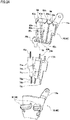
FIG. 2A is an exploded perspective view showing a state before connectors are received in a receiving portion ofFIG. 1 . -
FIG. 2B is an exploded perspective view of the receiving portion subsequent toFIG. 2A . -
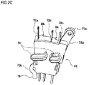
FIG. 2C is an overall perspective view of the receiving portion, in which the connectors are received. -
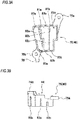
FIG. 3A is a side view of a container portion ofFIG. 2A . -
FIG. 3B is a top view of the container portion ofFIG. 2A . -
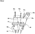
FIG. 4 is an overall perspective view showing a variant of the receiving portion ofFIG. 2C . -
FIG. 5 is a schematic longitudinal sectional view of a body portion of the electric power tool taken at a position of the receiving portion. -
FIG. 6 is a partial perspective view of a rear portion of the body portion of the electric power tool showing another variant of the receiving portion. -
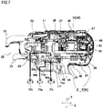
FIG. 7 is a partially enlarged side view of the body portion of the electric power tool showing a connector connection portion, as viewed from the inside thereof. -
FIG. 8 is a partially enlarged side view of the body portion of the electric power tool showing the connector connection portion, as viewed from the outside thereof. -
FIG. 9 is an exploded perspective view of the body portion of the electric power tool showing a state of a first wiring protection portion on the front side thereof. -
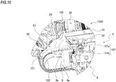
FIG. 10 is an enlarged perspective view of the vicinity of the trigger switch ofFIG. 9 . -
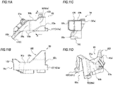
FIGS. 11A to 11D are part views of the first wiring protection portion. -
FIG. 11A is a side view,FIG. 11B is a bottom view,FIG. 11C is a sectional view take along an A-A line inFIG. 11A, and FIG. 11D is a perspective view. -
FIG. 12 is an exploded perspective view of the body portion of the electric power tool showing a state of a second wiring protection portion on the rear side of, as viewed obliquely from the rear lower side. -
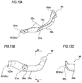
FIGS. 13A to 13C are part views of the second wiring protection portion.FIG. 13A is a perspective view,FIG. 13B is a side view, andFIG. 13C is a sectional view taken along a B-B line inFIG. 13B . - Hereinafter, the present embodiment will be described in detail with reference to the accompanying drawings.
FIGS. 1 to 13B are intended to describe the present embodiment. -
FIG. 1 shows abinding machine 1 as an example of an electric power tool. Arrows in the figure represent, respectively, afirst direction 2 corresponding to a horizontal direction of thebinding machine 1, a second direction 3 perpendicular to thefirst direction 2 and also corresponding to a vertical direction of thebinding machine 1, and a third direction 4 perpendicular to thefirst direction 2 and the second direction 3 and also corresponding to a widthwise direction of thebinding machine 1. - The binding
machine 1 is an electric power tool intended to bind an object or a work piece, such as reinforcingbars 5, with a binding member, such as awire 6. The bindingmachine 1 includes a twistingunit 25 configured to twist a binding member, such as awire 6, which is guided in a loop shape to wrap around an object, such as reinforcingbars 5, and thus to bind the object, such as reinforcingbars 5; atwist motor 27 for driving the twistingunit 25; acircuit board 32 having a mountingsurface 32a, on which a control unit 40 (seeFIG. 6 ) for controlling thetwist motor 27 is mounted; abody portion 7 for housing the twistingunit 25, thetwist motor 27 and thecircuit board 32. Ahandle portion 8 extending outward, i.e., substantially in the second direction 3, is provided on the substantially middle part of thebody portion 7 in thefirst direction 2. Thebody portion 7 has a generally hollow case extending in thefirst direction 2. In the following, reinforcingbars 5 as the object and awire 6 as the binding member will be described by way of example. Also, in thefirst direction 2, a side of thebody portion 7 facing the reinforcingbars 5 is referred to a front side of thebody portion 7, and the opposite side thereof is referred to as a rear side of thebody portion 7. Further, in the second direction 3, a side of thebody portion 7, on which thehandle portion 8 is provided, is referred to as a lower side of thebody portion 7, and the opposite side thereof is referred to as a upper side of thebody portion 7. Meanwhile, it should be noted that thebody portion 7 can be oriented in various directions depending on a working posture of thebinding machine 1 and thus the front/rear sides and the upper/lower sides are relative. The third direction 4 is a direction corresponding to a left and right direction of a worker, who holds thebinding machine 1, and is represented as a direction perpendicular to the paper surface of the figure (the far side is the right side and the near side is the left side). - The
handle portion 8 is provided on thebody portion 7 for the purpose of easily performing a work while holding the bindingmachine 1. Thus, in order to easily grip thehandle portion 8, thehandle portion 8 is attached on thebody portion 7 at an angle slightly inclined toward the front side of thebody portion 7 in thefirst direction 2. Thehandle portion 8 is formed by a generally hollow member. In the following, a portion (upper end portion) of thehandle portion 8 facing thebody portion 7 is referred to as a base portion or root portion of thehandle portion 8, and the opposite portion thereof (lower end portion) is referred to as a distal end portion of thehandle portion 8. Electric components, such as atrigger switch 9 as an activation switch, are provided on a front side of the root portion of thehandle portion 8. Also, abattery 11 as a power supply is detachably attached on the distal end portion of thehandle portion 8 via abattery attaching portion 12. Then, the bindingmachine 1 is activated by pulling thetrigger switch 9 in a state where the bindingmachine 1 is turned on. - On a lower portion of the
body portion 7, which is located in the rear of thehandle portion 8, aload supporting portion 67 may be provided to be placed on the back of a worker's hand and thus to support a load. At a location, which is located in front of theload supporting portion 67 but in the rear of the root portion of thehandle portion 8, a recessedportion 66 may be provided by scraping out the entire lower portion of thebody portion 7 to allow the back of the hand gipping thehandle portion 8 to be inserted therein. By providing the recessedportion 66 in this way, the handle portion 8 (and thus a gripping position thereon) relative to thebody portion 7 can be provided to be closer to the upper side or center portion of thebody portion 7 than the existing one. Correspondingly, a position of the middle finger when thehandle portion 8 is gripped (a location in the vicinity of a lower end of the trigger switch 9) can be brought closer to thecentroid position 68 of thebinding machine 1 than before. Accordingly, a weight balance of thebinding machine 1 can be improved and also operability of thebinding machine 1 can be enhanced. Meanwhile, thecentroid position 68 of thebinding machine 1 is determined by a weight of thebody portion 7 and a weight of thebattery 11 and generally corresponds to the position as shown inFIG. 1 and the like. - The binding
machine 1 is configured to bind the reinforcingbars 5 by twisting thewire 6, which is guided in a loop shape to wrap around the reinforcing bars 5. Thewire 6 is consumables and thus thewire 6 wound around a reel 13 (seeFIG. 8 ) can be used. Thebody portion 7 is provided, on the rear portion thereof (e.g., on the right side thereof), with a mount portion (reel mount portion) 14 (seeFIG. 8 ) allowing thereel 13 to be rotatably mounted thereon. Themount portion 14 is provided with a reel detection unit having electric components, such as a sensor capable of detecting an attached or detached state of thereel 13. The reel detection unit is attached on thebody portion 7 while being mounted on a sub-board. Themount portion 14 is provided with a brake unit for regulating rotation of thereel 13. The brake unit is configured to brake rotation of thereel 13, for example, at a time when delivery of thewire 6 is ended. The brake unit has a driving portion such as asolenoid 17. The driving portion such as thesolenoid 17 is attached on the substantially middle portion (an upper portion thereof) of thebody portion 7. Thewire 6 drawn out from thereel 13 mounted on themount portion 14 is delivered to the front side of thebody portion 7 by a wire feeding unit 18 (seeFIG. 8 ). Thewire feeding unit 18 is provided on the substantially middle portion of thebody portion 7. Thewire feeding unit 18 has a driving portion constructed by an electric motor, such as a feedingmotor 18a (seeFIG. 8 ), and feeding gears driven by the feedingmotor 18a. - The
body portion 7 is provided, on a front end portion thereof, with curl guides 21, 22 configured to curl thewire 6 and then to guide thewire 6 in a loop shape around the reinforcing bars 5. Thewire 6 is guided by the curl guides 21, 22 in such a manner that thewire 6 is wrapped in one turn or a plurality of turns around the reinforcing bars 5. The curl guides 21, 22 are provided in a pair while having a gap therebetween in the vertical direction (second direction 3) of thebinding machine 1. Since the reinforcingbars 5 have to be inserted between the pair of curl guides 21, 22, an opening portion (insertion portion) 23 is provided therebetween. The pair of curl guides 21, 22 are provided to have different lengths in such a manner that the upper side (curl guide 21) is longer and the lower side (curl guide 22) is shorter. Theupper curl guide 21 is fixed (fixed curl guide). Thelower curl guide 22 may be fixed or movable (movable curl guide). In the present embodiment, thelower curl guide 22 is attached on thebody portion 7 to be pivotable in the second direction, i.e., in the vertical direction, about acurl guide shaft 24 extending in the third direction 4. - The
body portion 7 is provided with the twistingunit 25 configured to perform binding by twisting the loop-shapedwire 6 wound around the reinforcingbars 5 to reduce a diameter of the loop. The twistingunit 25 is formed in a generally shaft shape extending in thefirst direction 2. The twistingunit 25 is connected to an output shaft of thetwist motor 27, which protrudes from one end side thereof, via aspeed reduction mechanism 26. Then, the twistingunit 25 is operated by rotationally driving thetwist motor 27. - Various driving portions installed in the
binding machine 1, such as the feedingmotor 18a, thetwist motor 27 and thesolenoid 17, are sequentially controlled by thecontrol unit 40. Thecontrol unit 40 is mounted on the circuit board 32 (control board or main board). Thecircuit board 32 is installed between thetwist motor 27 inside thebody portion 7 and aninner wall surface 34 thereof facing thehandle portion 8, while being received in acircuit board case 33. Thecircuit board case 33 is formed as a shallow dish or flat box-shaped container having, on one face thereof, an opening portion allowing thecircuit board 32 to be received therein. As viewed in a plan view, thecircuit board 32 has a generally quadrangular shape, and a shape of thecircuit board case 33 in the plan view is generally similar to that of thecircuit board 32. Thecircuit board case 33 is fixed to a side surface of the body portion 7 (afirst body portion 54 as described below) by fixingportions 56. Also, the bindingmachine 1 is installed with asetting unit 35 capable of setting operation conditions of thebinding machine 1, specifically operation conditions of various driving portions, such as the feedingmotor 18a, thetwist motor 27 and thesolenoid 17. For example, the settingunit 35 is configured to set the number of turns of thewire 6 wound around the reinforcingbars 5, an operation time of the feedingmotor 18a, an operation timing of thesolenoid 17, an amount of torque of thetwist motor 27 and the like. The settingunit 35 is mounted on aswitch board 37, together with electric components, such as a main power switch ormain switch 36 for turning on and off the power supply. Also, various driving portions, such as the feedingmotor 18a, thetwist motor 27 and thesolenoid 17; various circuit boards, such as the circuit board 32 (main board), theswitch board 37 and the sub-board; and a battery 11 (a battery board provided inside the battery), which are installed in thebinding machine 1, are connected to each other by various wirings. The various wirings include, for example,power supply wirings 38, signal wirings 39 and the like. The wirings, such aspower supply wirings 38 and signal wirings 39, are arranged inside thebody portion 7. - With respect to the basis configuration as described above, the electric power tool of the present embodiment is configured as follows.
- (1) The electric power tool of the present embodiment includes a driving unit generating a driving force by electricity and various components functioning by electricity; a
circuit board 32, on which acontrol unit 40 for controlling the driving unit and the various components is mounted; a plurality ofconnectors 71a to 71c (seeFIGS. 2A to 2C ) for connecting a plurality ofwirings 72a to 72c (seeFIGS. 2A to 2C ), which extend from the driving unit and the various components, with a plurality ofwirings 72a to 72c, which extend from thecircuit board 32; abody portion 7 installed therein with the driving unit, the various components, the circuit board 32 (seeFIG. 6 ) and the plurality ofconnectors 71a to 71c; and a receivingportion 46 configured to receive the plurality ofconnectors 71a to 71c therein and to be fixed to thebody portion 7. - Herein, the electric power tool is not limited to the
binding machine 1 as described above, but the structure of the present embodiment can be appropriately applied to thebinding machine 1. Thebody portion 7 is configured to be dividable into afirst body portion 54 and asecond body portion 55 in the widthwise direction (third direction 4 or left and right direction) (seeFIG. 5 ). In the case of thebinding machine 1, the driving unit is thesolenoid 17 of the brake unit, thefeeing motor 18a of thewire feeding unit 18, thetwist motor 27 for driving the twistingunit 25 or the like, in particular the twistingmotor 27. In the case of thebinding machine 1, the components includes the sensor of the reel detection unit, thetrigger switch 9, the settingunit 35, themain switch 36, a light source, such as a LED, for indicating an on/off state of themain switch 36, or the like. - As shown in
FIGS. 2A to 2C , theconnectors 71a to 71c are provided singularly or in plural on an end portion or a middle portion ofwirings 72a to 72c constituting thepower supply wirings 38 , the signal wirings 39 or the like. Theconnectors 71a to 71c may be individual connectors capable of individually connecting wirings one by one, but in the present embodiment, are configured as a collective connector capable of collectively connecting a plurality ofwirings 72a to 72c at once. For example, a plurality ofconnectors 71a to 71c can be separately provided for each number ofwirings 72a to 72c, for each thickness of wirings, for each component (or board) to be connected, or the like. In the present embodiment, afirst connector 71a is provided to be capable of connecting fivefirst wirings 72a having the thinnest thickness at once. Also, asecond connector 71b is provided to be capable of connecting foursecond wirings 72b having a medium thickness (thicker than thefirst wirings 72a but thinner thanthird wirings 72c) at once. Athird connector 71c is provided to be capable of connecting twothird wirings 72c having the thickest thickness in the figures at once. However, the number ofconnectors 71a to 71c is not limited to three. Also, theconnectors 71a to 71c in the figures are shown in a state where male connectors and female connectors are connected to each other. - The receiving
portion 46 is configured in the shape of a box capable of receiving a plurality ofconnectors 71a to 71c. The receivingportion 46 is at least constituted of acontainer portion 75 having an opening portion in one surface thereof, and alid portion 76 for closing the opening portion of thecontainer portion 75. Thelid portion 76 is capable of closing or opening thecontainer portion 75 in the widthwise direction (third direction 4) of thebody portion 7. Thecontainer portion 75 and thelid portion 76 are fixed to each other by claws or screws. The receivingportion 46 is fixed to thebody portion 7 in the widthwise direction byfixtures 77 such as screws (seeFIG. 1 ), while the receivingportion 46 is received inside thebody portion 7. Therefore, attachingpieces container portion 75. Also, on an upper portion of thelid portion 76, an attachingpiece 76a is integrally provided to be fastened together with the upper attachingpiece 75a of thecontainer portion 75. On a lower portion of thelid portion 76, no attaching piece or the like is provided. In this configuration, by temporarily loosely fixing the lower attachingpiece 75b of thecontainer portion 75 to thebody portion 7 by means of thefixture 77, thecontainer portion 75 is allowed to be pivotally displaced (rearward) about the attachingpiece 75b. Also, for example, it is possible to attach theconnectors 71a to 71c to thecontainer portion 75 while thecontainer portion 75 is brought out of thebody portion 7. If theconnectors 71a to 71c have been attached to thecontainer portion 75, thelid portion 76 is attached to thecontainer portion 75, so that theconnectors 71a to 71c are received in the receiving portion (first receiving portion) 46. Thereafter, the receivingportion 46 is moved to a defined position inside the body portion 7 (by pivotally displacing the receivingportion 46 forward about the attachingpiece 75b). Then, the attachingpiece body portion 7 by means of thefixtures 77, and also the attachingpiece 75b is finally fixed to thebody portion 7 by thefixture 77. By adopting such a mounting method, it is possible to simplify the work and also to shorten thewirings 72a to 72c. - At this time, a
wiring restriction portion 78 may be provided on the receivingportion 46. For example, thewiring restriction portion 78 can be configured as a wiring arranging arm protruding from the lower attachingpiece 75b of thecontainer portion 75 downward (toward thecircuit board case 33 below thereof). Thewiring restriction portion 78 is intended to restrict wirings (e.g.,power supply wirings 38 inFIG. 5 ), which extend from lower to upper side by passing outside the receivingportion 46 after emerging, for example, from thecircuit board 32, thecircuit board case 33 and the like, and thus to arrange a flow or direction of the wirings. Accordingly, for example, by fixing the receivingportion 46 to thefirst body portion 54 constituting thebody portion 7, thewiring restriction portion 78 can naturally control wirings in the vicinity thereof, in such a manner that the wirings are guided outside the receivingportion 46. As a result, it is possible to enhance assemblability or maintainability of the wirings to thebody portion 7 or thecontainer portion 75. - Also, the receiving
portion 46 may be formed of an opaque member, but the receivingportion 46 may be entirely or partially formed of a transparent member or translucent member. Thus, a received state of theconnectors 71a to 71c in the receivingportion 46 can be visually identified. Therefore, it is possible to find and prevent defects, such as biting of theconnectors 71a to 71c by the receivingportion 46 or poor connection of theconnectors 71a to 71c. - (2) As shown in
FIG. 1 , the receivingportion 46 is arranged in the rear of the driving unit, i.e., the receivingportion 46 is arranged on the opposite side to the output shaft of thetwist motor 27. - The twisting
unit 25 is installed at a location inside thebody portion 7, which is located in front of thetwist motor 27, via thespeed reduction mechanism 26, and arear space 42 is formed in the rear of thetwist motor 27. The receivingportion 46 is installed in therear space 42. Thecircuit board 32 is arranged to be close to thetwist motor 27. In thebinding machine 1, thecircuit board 32 is the above main board. Thecircuit board 32 is arranged upside down in such a manner that the mountingsurface 32a (seeFIG. 6 ) faces thehandle portion 8 and the back surface (soldering surface) thereof faces thetwist motor 27. Thecircuit board 32 is arranged between thetwist motor 27 and thehandle portion 8 in such a manner that thecircuit board 32 is closer to thetwist motor 27 than the inner wall surface 34 (bottom wall) of thebody portion 7, which is located toward thehandle portion 8. For example, on the basis of thecurl guide shaft 24 positioned between theinner wall surface 34 and the twist motor 27 (in the second direction 3), thecircuit board 32 is arranged at a height substantially equal to or higher than that of thecurl guide shaft 24. A heat resistant member, such as a heat resistant sheet 41 (seeFIG. 1 ), may be interposed between thecircuit board 32 and thetwist motor 27 as required. The heatresistant sheet 41 can be installed by attaching rubber or resin on an upper surface of thecircuit board case 33. In this way, by interposing the heat resistant member, such as the heatresistant sheet 41, between thecircuit board 32 and thetwist motor 27, it is possible to protect thecircuit board 32 from heat generated by thetwist motor 27. Also, since the heatresistant sheet 41 is formed of rubber, resin or the like, the effect thereof as a vibration-proof material can be anticipated. - (3) As shown in
FIGS. 3A and 3B , the receivingportion 46 has a plurality ofchambers 82a to 82c partitioned inside thereof. The plurality ofchambers 82a to 82c are partitioned bypartitions 81aconnectors 71a to 71c. In the present embodiment, one of theconnectors 71a to 71c is received in each of thechambers 82a to 82c. Alternatively, for example, a plurality of (e.g., two)connectors 71a to 71c may be received in onechamber 82a to 82c (any one thereof). - The
partitions wirings 72a to 72c. In the case, the receivingportion 46 is partitioned into three chambers arranged generally in the front and rear direction by twopartitions - (4) Each of the plurality of
chambers 82a to 82c is configured to have a shape matching with a shape of the plurality ofconnectors 71a to 71c to be received therein. Also, each of the plurality ofchambers 82a to 82c is configured to have a different shape to match with a shape of each of theconnectors 71a to 71c. Alternatively, depending on shapes of theconnectors 71a to 71c to be received (e.g., in a case where all of theconnectors 71a to 71c to be received have the same shape, or a case where only some of theconnectors 71a to 71c have different shapes), all of the plurality ofchambers 82a to 82c may have the same shape or at least two of the plurality ofchambers 82a to 82c may have a different shape. Also, similarly to the shapes of thechambers 82a to 82c, thechambers 82a to 82c may configured not only such that all have different sizes, but also such that all have the same size or at least two sizes are employed. - Herein, the
first connector 71a, thesecond connector 71b and thethird connector 71c shown inFIG. 2A have different width dimensions and shapes in accordance with difference in the number or thickness of thewirings 72a to 72c to be connected. Then, thechambers 82a to 82c of the receivingportion 46 are also configured to have different depths or sizes depending on theconnectors 71a to 71c. At locations on a peripheral wall portion of the receiving portion 46 (i.e., of thecontainer portion 75 thereof), which correspond to upper and lower portions of each of thechambers 82a to 82c, slits 83a to 83c are provided to allow thewirings 72a to 72c to pass therethrough. Similarly, theslits 83a to 83c are also formed to have different depths or widths depending on the number or thickness of thewirings 72a to 72c. The receivingportion 46 may be configured to have a width dimension based on the widest one of theconnectors 71a to 71c. Also, as shown inFIG. 2C , step-shapedportions 84 may be provided on a side surface of thecontainer portion 75 opposite to the opening portion, in accordance with difference in width dimension of theconnectors 71a to 71c. Alternatively, as shown inFIG. 4 , the step-shapedportions 84 may be provided on thelid portion 76. - (5) As shown in
FIG. 5 , the receivingportion 46 is fixed to be spaced frominner side walls body portion 7. Therefore, predetermined spaces (second receiving portions) 87, 88 are formed between the receivingportion 46 and theinner side walls - Herein, the
inner side walls body portion 7 means inner walls of side surfaces of thebody portion 7, which are oriented in the widthwise (right and left) direction (third direction 4), namely, inner walls of side surfaces of thebody portion 7, which are located along a direction substantially perpendicular to an axial direction of thetwist motor 27 and also substantially perpendicular to a longitudinal direction of thehandle portion 8. By arranging the receivingportion 46 to be spaced from oneinner side wall 85, 86 (any one thereof), a predetermined space, i.e., a widthwise gap (second receiving portion) 87, 88 is formed between the receivingportion 46 and theinner side walls power supply wirings 38, signal wirings 39 and the like) can be arranged to pass through the space or the widthwise gap (second receiving portion) 87, 88. Thus, in the electric power tool of the present embodiment, connectors or wirings can be arranged to pass inside and outside the receivingportion 46, thereby making full use of the empty space in thebody portion 7. - (6) The receiving
portion 46 includes a firstouter surface 79 opposing oneinner side wall 85 of thebody portion 7 and a secondouter surface 80 located opposite to the firstouter surface 79 and opposing the otherinner side wall 86, and also awiring holding portion 91 for holding wirings is provided on the secondouter surface 80. - For example, the
wiring holding portion 91 is configured as a hook portion so that wirings (power supply wirings 38, signal wirings 39 and the like) extending generally in the vertical direction can be received and held therein. For example, the hook portion is configured such that a distal end thereof is bent toward the front side of thebody portion 7, although a direction of the hook portion may be set to any direction. By bending the hook portion toward the front side, wirings received in thewiring holding portion 91 can be constrained not to protrude rearward, thereby preventing the wirings from being caught in the rear portion of thebody portion 7. One or a plurality ofwiring holding portions 91 may be provided. Alternatively, thewiring holding portion 91 may be provided on the firstouter surface 79 or on both the firstouter surface 79 and the secondouter surface 80. - (7) As shown in
FIG. 6 , as another embodiment, the receivingportion 46 may be integrally formed inside thebody portion 7. - Herein, the receiving
portion 46 can be integrated with thebody portion 7, for example, by forming aportion 92 of thecontainer portion 75, which corresponds to the attachingpieces - (8) As shown in
FIGS. 7 and8 , thebody portion 7 has a plurality of openings (connector connection portions 94a to 94c) extending from inside to outside of thebody portion 7, and the plurality of openings have shapes matching respectively with shapes of a plurality ofconnectors 71d to 71i to hold the plurality ofconnectors 71d to 71i. - Herein, the
connector connection portions 94a to 94c are provided separately from the receivingportion 46 as described above, but may be provided in place of the receivingportion 46. Theconnector connection portions 94a to 94c are formed to be individually matched with theconnectors 71d to 71i, which are different in size or shape in accordance with the number of wirings to be connected, a thickness of wirings, a component (or board) to be connected or the like. Also,male connectors 71d to 71f are inserted into theconnector connection portions 94a to 94c from the outside or inside of the body portion 7 (e.g., the first body portion 54), and then themale connectors 71d to 71f are locked on thebody portion 7 by claw portions or the like. Then,female connectors 71g to 71i mating with themale connectors 71d to 71f are fitted into themale connectors 71d to 71f from the inside or outside of thebody portion 7. Accordingly, theconnectors 71d to 71i are coupled to sandwich thebody portion 7 therebetween. Meanwhile, in the present embodiment, theconnector connection portions 94a to 94c are installed in front of thecircuit board 32 and thecircuit board case 33 and also between the twistingunit 25 and thetrigger switch 9. - (9) As shown in
FIG. 1 , the binding machine (electric power tool) 1 may havewiring protection portions body portion 7 for protecting wirings (e.g.,power supply wirings 38, signal wirings 39, other wirings and the like). - Herein, the
wiring protection portions body portion 7, which is located close to a peripheral edge portion of thebody portion 7, to generally extend along the peripheral edge portion of thebody portion 7. In the present embodiment, as shown inFIG. 9 , a firstwiring protection portion 95 is provided at a location on a lower portion of thefirst body portion 54 constituting thebody portion 7, which is located in front of thehandle portion 8. Also, as shown inFIG. 12 , a secondwiring protection portion 96 is provided at a location in the rear of thehandle portion 8. For example, the first wiring front-sidewiring protection portion 95 can be provided in the vicinity of thetrigger switch 9. Also, the second rear-sidewiring protection portion 96 can be provided in the recessedportion 66, which is provided in the rear of thehandle portion 8, or at a location in the rear of the recessedportion 66. - The
wiring protection portions wiring protection portions fixtures 97 such as screws. Therefore, thewiring protection portions screw holes 98a formed therein. Also,screw supporting portions 97b, such as boss portions, allowing thefixtures 97, such as screws, to be screwed therein are provided on the body portion 7 (e.g., the first body portion 54). Preferably, thewiring protection portions body portion 7 by screwing the screws from the third direction 4 (from the left side). Thewiring protection portions body portion 7 after the wirings are installed in thebody portion 7. Alternatively, thewiring protection portions body portion 7 before the wirings are installed therein, and then the wirings may be installed to extend along thewiring protection portions - Specifically, as shown in
FIG. 9 , the first front-sidewiring protection portion 95 is installed above thetrigger switch 9 in such a manner that thefemale connectors 71g to 71i inside thebody portion 7, which are attached to theconnector connection portions 94a to 94c (seeFIG. 7 ) installed between the twistingunit 25 and thetrigger switch 9, or wirings extending from thefemale connectors 71g to 71i can be covered and protected therewith from the third direction 4 (from the left side). As shown in the enlarged view ofFIG. 10 , front and lower sides of thetrigger switch 9 are surrounded by atrigger guard 9a, and aslide portion 9b for guiding forward and rearward movement of thetrigger switch 9 is provided at a location within an installation range of thetrigger guard 9a, which corresponds to a lower edge portion of the body portion 7 (e.g., first body portion 54). Then, the firstwiring protection portion 95 is attached at a location above theslide portion 9b. - The first
wiring protection portion 95 is configured to form a generally closed wiring passage between thebody portion 7 and the firstwiring protection portion 95 when being attached on thebody portion 7. Accordingly, as shown in the part view ofFIGS. 11A to D , the firstwiring protection portion 95 is a generally C- or U-shaped cross-sectional member having a lower surface portion (first surface portion) 95a, an upper surface portion (second surface portion) 95b, and aside surface portion 95c connecting one-side portions (left portions) of thelower surface portion 95a andupper surface portion 95b. The firstwiring protection portion 95 extends in the front and rear direction (first direction 2) over the entire installation range of thetrigger guard 9a and has openingportions body portion 7. Also, the other-side portions (right portions) of thelower surface portion 95a andupper surface portion 95b are spaced from each other to open therebetween. At least thelower surface portion 95a can be provided, on the other-side portion thereof, with a portion arranged on an upper side of theslide portion 9b at the lower edge portion of thebody portion 7 and thus overlapping with theslide portion 9b in the vertical direction. Meanwhile, other configurations of the firstwiring protection portion 95 will be described below. - Also, as shown in
FIG. 1 , the second rear-sidewiring protection portion 96 is installed to generally extend along a lower edge portion of the rear portion of thebody portion 7 in such a manner that inverted-from-downward-to-upward parts of wirings (power supply wirings 38 or the like), which emerge and extend downward from the rear portion of the circuit board (main board) 32 and then routed upward generally along the rear end portion of the body portion 7 (e.g., first body portion 54), are mainly protected (or pressed) therewith and thus the wirings are prevented from poking out of the body portion 7 (in the third direction 4 (left side), first direction 2 (rear side) or the like). The secondwiring protection portion 96 is configured such that, when being attached on thebody portion 7, an upright wall capable of constraining the wirings from the left side is formed between thebody portion 7 and the secondwiring protection portion 96. Also, as shown in the part view ofFIGS. 13A to C , in order to form a wiring path opened upward, the secondwiring protection portion 96 is a generally L- or J-shaped cross-sectional member having a lower surface portion (first surface portion) 96a and aside surface portion 96b erected upward from one-side portion of thelower surface portion 96a to form the upright wall. The secondwiring protection portion 96 extends generally in the front and rear direction (first direction 2) along the recessedportion 66 and a portion in the rear thereof. At least thelower surface portion 96a can be provided, on the other-side portion thereof, with a portion arranged on an upper side of the lower edge portion of thebody portion 7 and thus overlapping with the lower edge portion in the vertical direction. Meanwhile, other configurations of the secondwiring protection portion 96 will be described below. - (10) As shown in
FIG. 1 , thewiring protection portions rotation restricting portions wiring protection portions body portion 7. Therotation restricting portions wiring protection portions body portion 7. - Herein, the
rotation restricting portions wiring protection portions wiring protection portions fixtures 97, such as screws, in a screwing direction thereof (e.g., clockwise direction) when thewiring protection portions fixtures 97. Therotation restricting portions fixtures 97. - Specifically, as shown in
FIG. 9 , thescrew hole 97a used for attaching the firstwiring protection portion 95 is provided at a location in front of the middle part, in the front and rear direction (first direction 2), of theupper surface portion 95b. Also, therotation restricting portion 98 for the firstwiring protection portion 95 has a rotation restrictingconcave portion 98a provided at a location in the rear of the middle part, in the front and rear direction, of theupper surface portion 95b, and a rotation restrictingconvex portion 98b protruding from the body portion 7 (e.g., first body portion 54) toward the rotation restrictingconcave portion 98a. Then, when the firstwiring protection portion 95 is set on thebody portion 7, the rotation restrictingconvex portion 98b is fitted into the rotation restrictingconcave portion 98a, thereby restricting rotation upon screwing of thefixture 97. The rotation restrictingconcave portion 98a may be configured as a hole portion, such as a pin hole, provided in the firstwiring protection portion 95, and the rotation restrictingconvex portion 98b may be configured as a protrusion, such as a pin, protruding from thebody portion 7. For example, the hole portion can be formed in a convex piece portion protruding upward theupper surface portion 95b of the firstwiring protection portion 95. The rotation restrictingconvex portion 98b can formed to protrude in the left direction (third direction 4) from a location on the body portion 7 (e.g., first body portion 54), which corresponds to the hole portion. - Also, as shown in
FIG. 12 , thescrew hole 97a used for attaching the secondwiring protection portion 96 is provided at a location on the substantially middle part, in the front and rear direction, of the secondwiring protection portion 96. The location is located in front of the wirings to be protected by the secondwiring protection portion 96. Meanwhile, in order to prevent thefixture 97, such as a screw, from being directly in contact with the wirings, a box-shapedcover 99c (seeFIGS. 13A to 13C ) may be provided around thescrew hole 97a. Also, therotation restricting portion 99 for the secondwiring protection portion 96 has a protrudingpiece portion 99a protruding generally forward from the front end portion of the secondwiring protection portion 96, and a rotation restricting rib 99b protruding from thebody portion 7 in the left direction (third direction 4). The rib 99b is formed to extend over and along theinner wall surface 34 of the lower edge portion of thebody portion 7 in such a manner that a gap substantially equal to a thickness of the protrudingpiece portion 99a is defined therebetween. Accordingly, when the secondwiring protection portion 96 is set on thebody portion 7, the protrudingpiece portion 99a can be inserted and held (or sandwiched) between the rib 99b and the lower edge portion of thebody portion 7. The rib 99b and the lower edge portion of thebody portion 7 constitute a sandwiching portion capable of sandwiching the protrudingpiece portion 99a. Then, when the secondwiring protection portion 96 is set on thebody portion 7, the protrudingpiece portion 99a is sandwiched between the rib 99b and the lower edge portion of thebody portion 7, thereby restricting rotation upon screwing of thefixture 97. - (11) In the following, other configurations of the first
wiring protection portion 95 will be described. - (a) As shown in
FIG. 9 (to FIG. 11D ), asensor 101 for detecting pivoting of thelower curl guide 22 about thecurl guide shaft 24 in the vertical direction is provided in the vicinity of the front end portion of the firstwiring protection portion 95. For example, thesensor 101 may be configured as a push switch or the like. Thesensor 101 is installed to be received at a location on the front upper portion of thetrigger guard 9a. Also, the firstwiring protection portion 95 may be provided, in the vicinity of the front end portion thereof, with a retaining portion 102 (sensor retainer) for preventing thesensor 101 from falling out of thebody portion 7. The retainingportion 102 is configured as a locking portion for retaining (locking and holding) a left surface of thesensor 101 from the left side. The locking portion is formed by providing a convex-shaped portion, which has a length reaching the left surface of thesensor 101, on a distal end portion of the firstwiring protection portion 95. By providing the convex-shaped portion, the distal end portion of the firstwiring protection portion 95 has a stepped or cutout shape at thelower surface portion 95a orupper surface portion 95b. Accordingly, thesensor 101 can be retained by the stepped or cutout-shaped distal end portion. In this way, by providing the retainingportion 102 on the firstwiring protection portion 95, it is possible to prevent thesensor 101 from falling out of the body portion 7 (or the front upper portion of thetrigger guard 9a). Further, since the firstwiring protection portion 95 is fixed to thebody portion 7, thesensor 101 can be stably held between thebody portion 7 and the retainingportion 102. - (b) The first
wiring protection portion 95 may be provided with anenlarged cross-section portion 105 for preventing wirings to be protected from being sharply bent. In the present embodiment, wirings extending from thefemale connectors 71g to 71i in the third direction 4 (left direction) are greatly reversed to be routed in the right direction immediately after that. Subsequently, the wirings pass by front of a front side portion of thecircuit board case 33 and then are guided to an inner portion of the body portion 7 (e.g., the first body portion 54) (i.e., to the right side of the circuit board case 33). At this time, if the wirings are excessively bent, there is a risk that defects, such as disconnection, occur in the wirings. Therefore, in order to maintain the bent section of the wirings in a more gentle shape, a cross section of the firstwiring protection portion 54, in which the bent section of the wirings and the vicinity thereof are arranged, is enlarged toward the third direction 4 to form theenlarged cross-section portion 105. Theenlarged cross-section portion 105 can be formed to have a desired size within a width range of thebody portion 7 in the third direction 4. In the present embodiment, theenlarged cross-section portion 105 is shaped in such a manner that the cross section of the firstwiring protection portion 95 is enlarged toward the left side as it goes rearward. Meanwhile, the position or shape of theenlarged cross-section portion 105 of the firstwiring protection portion 95 can be appropriately changed depending on a bent shape of the wirings. In this way, by providing theenlarged cross-section portion 105 on the firstwiring protection portion 95, it is possible to reliably guide and protect wirings to be protected while protecting the wirings from being sharply bent. - (c) As shown in
FIG. 10 , ashape correction portion 107 capable of maintaining the firstwiring protection portion 95 in a normal shape may be provided between the firstwiring protection portion 95 and the body portion 7 (e.g., the first body portion). Theshape correction portion 107 is intended to restore the firstwiring protection portion 95 to the normal shape, for example, in a case where the firstwiring protection portion 95 is shrunk after molding, thereby ensuring that the firstwiring protection portion 95 can be attached on thebody portion 7 without any trouble. Specifically, a cross section of the firstwiring protection portion 95 taken in a plane perpendicular to the first direction 2 (front and rear direction) has a generally C- or U-shape. Accordingly, due to shrinkage, the other-side portions of theupper surface portion 95b andlower surface portion 95a are easy to be closed toward each other in the vertical direction. Therefore, theshape correction portion 107 can be configured to open the closed firstwiring protection portion 95 in the vertical direction, thereby restoring the original shape thereof. In particular, the firstwiring protection portion 95 is easy to be closed at the front and rear end portions and also at the position of theenlarged cross-section portion 105 due to shrinkage. Therefore, theshape correction portion 107 is preferably provided on at least one of the vicinity of the front and rear end portions and the vicinity of theenlarged cross-section portion 105. In the present embodiment, theshape correction portion 107 is provided on the rear end-side portion provided with theenlarged cross-section portion 105 and the like. - Specifically, the
shape correction portion 107 is configured as a protrusion, such as arib 107a, provided on thebody portion 7 for opening the firstwiring protection portion 95. Therib 107a abuts against an upper surface of thelower surface portion 95a of the firstwiring protection portion 95, which is located in the vicinity of the rear end portion thereof, thereby widening the firstwiring protection portion 95 and thus preventing biting of wirings. Therib 107a extends from the body portion in the left direction (third direction 4). On the other hand, if necessary, arib bearing portion 107b configured to surface-abut against therib 107a may be provided as theshape correction portion 107 on a portion of thelower surface portion 95a of the firstwiring protection portion 95, which is located toward the rear end portion thereof. In the present embodiment, therib bearing portion 107b is configured as a protruding piece protruding rearward from thelower surface portion 95a. Therib bearing portion 107b can be formed to be thicker than other portions of the firstwiring protection portion 95 in order to finely adjust an abutting position thereof against the abuttingportion 107a, to secure a required strength and the like. - In this way, since the
shape correction portion 107 is provided between the firstwiring protection portion 95 and the body portion 7 (e.g., first body portion 54), it is possible to restore (open) the shrunken firstwiring protection portion 95 to the normal shape by simply setting the firstwiring protection portion 95 on thebody portion 7 and then surface-abutting therib bearing portion 107b against therib 107a. Therefore, it can be ensured that the first wiring protection portion 95 (thelower surface portion 95a thereof) is positioned at a defined location on thebody portion 7. Meanwhile, with respect to theupper surface portion 95b of the firstwiring protection portion 95, therotation restricting portion 98 serves as a reference for an attaching position thereof and also as theshape correction portion 107, thereby ensuring that theupper surface portion 95b is installed at a correct position. - (12) In the following, other configurations of the second
wiring protection portion 96 will be described. - As shown in
FIG. 12 , asinking prevention portion 109 for preventing the secondwiring protection portion 96 from sinking down into thebody portion 7 may be provided between the body portion 7 (e.g., first body portion 54) and the secondwiring protection portion 96. If a restoring force of wirings, which have been pushed and bent by the secondwiring protection portion 96 when the secondwiring protection portion 96 has been set on thebody portion 7, causes one side (front or rear side), in the front and rear direction (first direction 2), of the secondwiring protection portion 96 to be lifted toward the near side in the third direction (left direction), the other side (rear or front side) is pushed into thebody portion 7 toward the far side in the third direction (right direction), thereby causing sinking of the secondwiring protection portion 96. The sinkingprevention portion 109 may be configured as front andrear stoppers 109b or displacement restricting portions provided, respectively, at locations on thebody portion 7, which correspond, respectively, to front and rear end portions of the secondwiring protection portion 96, so that the front and rear end portions of the secondwiring protection portion 96 are born thereon in the third direction 4. Thestoppers 109b can be formed as ribs, ridges or the like for restricting, respectively, the front and rear end portions of the secondwiring protection portion 96 so as not to be displaced toward the far side in the third direction 4 by more than a predetermined amount. The ribs or ridges for the stoppers protrude from thebody portion 7 in the left direction (third direction 4) to have a height preventing the secondwiring protection portion 96 from being displaced more toward the far side than the correct position thereof. On the other hand, on at least one of the front and rear end portions of the secondwiring protection portion 96, a bearingportion 109a can be appropriately provided to stably bear the front andrear stoppers 109b with respect to the third direction 4. In the present embodiment, thefront bearing portion 109a is formed on a portion (side surface) of the protrudingpiece portion 99a constituting therotation restricting portion 99, which faces the body portion 7 (e.g., the first body portion 54). This front sinkingprevention portion 109 is integrally formed with the rib 99b of therotation restricting portion 99. Also, therear bearing portion 109a is formed as a cutout portion formed in thelower surface portion 95a. - <Operation> Hereinafter, operation of the present embodiment will be described.
- The
reel 13 having thewire 6 wound thereon is mounted on themount portion 14, and then themain switch 36 is turned on. In this state, the distal end of thebody portion 7 is oriented toward reinforcingbars 5, the reinforcingbars 5 are inserted between the upper and lower curl guides 21, 22, and then thetrigger switch 9 is pulled. As a result, thewire feeding unit 18 is activated so that thewire 6 is drawn out from thereel 13 and then is delivered to the front side of thebody portion 7. Thewire 6 delivered to the front side of thebody portion 7 is curled by the curl guides 21, 22 and also guided to be wrapped in one turn or a plurality of turns around the reinforcing bars 5. Thereafter, the loop-shapedwire 6 wound around the reinforcingbars 5 is twisted by the twistingunit 25, so that a diameter of the loop is reduced, thereby binding the reinforcing bars 5. - The electric power tool, such as the binding
machine 1 as described above, includes, in thebody portion 7, the driving unit, such as a motor; various components, such as sensors or LEDs; thecircuit board 32, on which thecontrol unit 40 is mounted; theconnectors 71a to 71c for electrically connecting therebetween and the like. If thebody portion 7 has only a structure, in which theconnectors 71a to 71c are simply pushed into the inside of thebody portion 7 when routing thewirings 72a to 72c, assemblability or maintainability to thebody portion 7 is deteriorated. -
- (Effect 1) The plurality of
connectors 71a to 71c are received and held in the receivingportion 46, and then the receivingportion 46 is fixed to thebody portion 7. Therefore, it is possible to enhance assemblability and maintainability of the plurality ofconnectors 71a to 71c to thebody portion 7. Since the plurality ofconnectors 71a to 71c are collectively received in the receivingportion 46, a receiving space, which has to be secured in thebody portion 7 in order to receive the plurality ofconnectors 71a to 71c, can be reduced, thereby allowing downsizing of thebody portion 7. Since the receivingportion 46 is fixed to thebody portion 7, theconnectors 71a to 71c received in the receivingportion 46 are hardly shaken due to vibration or the like, thereby making it difficult for theconnectors 71a to 71c to be damaged. Therefore, it is possible to enhance quality performance of the electric power tool. - (Effect 2) The receiving
portion 46 is arranged in the rear of the driving unit, i.e., on the opposite side to the output shaft of thetwist motor 27. Therefore, a part of the electric power tool, which serves as a tool (twistingunit 25 in the case of thebinding machine 1 and the like), can be arranged in front of thebody portion 7, the driving unit can be arranged in the rear of thebody portion 7, thecircuit board 32 can be arranged to be close to the driving unit, and also the receivingportion 46 can be arranged in therear space 42 in the rear of thetwist motor 27. As a result, the empty space in the rear of thetwist motor 27 can be effectively utilized. Also, distances among various components and thecircuit board 32 and theconnectors 71a to 71c are shortened, thereby facilitating arranging or routing of theconnectors 71a to 71c in thebody portion 7. Therefore, it is possible to downsize thebody portion 7 and to enhance operability of the electric power tool. - (Effect 3) The plurality of
chambers 82a to 82c are provided inside the receivingportion 46. Therefore, theconnectors 71a to 71c can be received in the plurality ofchambers 82a to 82c, or the plurality ofconnectors 71a to 71c can be individually received and fixed therein. As a result, it is possible to enhance assemblability and maintainability of theconnectors 71a to 71c to the receivingportion 46. Also, the plurality ofchambers 82a to 82c are partitioned by thepartitions connectors 71a to 71c from interfering with each other inside the receivingportion 46. Thus, it is possible to suppress the plurality ofconnectors 71a to 71c from being shaken due to vibration or the like, thereby making it difficult for theconnectors 71a to 71c to be damaged. Therefore, it is possible to enhance quality performance of the electric power tool. - (Effect 4) The shapes of the plurality of
chambers 82a to 82c match respectively with the shapes of the plurality ofconnectors 71a to 71c to be received therein. Therefore, theconnectors 71a to 71c can be individually fitted into therespective chambers 82a to 82c, so that theconnectors 71a to 71c are not shaken due to vibration or the like, thereby making it difficult for theconnectors 71a to 71c to be damaged. Thus, it is possible to enhance quality performance of the electric power tool. Also, the plurality ofchambers 82a to 82c are configured to have different shapes to match with the shapes of theconnectors 71a to 71c. Therefore, connectors having different shapes can be used as the plurality ofconnectors 71a to 71c, thereby preventing theconnectors 71a to 71c from being misassembled. - (Effect 5) The receiving
portion 46 is fixed to be spaced from theinner side walls body portion 7. Thus, thesecond receiving portions portion 46 and theinner side walls power supply wirings 38, signal wirings 39 and the like) installed inside thebody portion 7 can be held by thesecond receiving portions connectors 71a to 71c (and thus thewirings 72a to 72c having theconnectors 71a to 71c) and the other wirings can be separated to be hierarchically held in the inside and outside of the receivingportion 46. Accordingly, it is possible to enhance assemblability and maintainability of theconnectors 71a to 71c or the wirings to thebody portion 7. - (Effect 6) The
wiring holding portion 91 is provided on theouter surfaces portion 46, which oppose theinner side walls body portion 7. In particular, thewiring holding portion 91 is provided on the secondouter surface 80 of the receivingportion 46. Therefore, by using thewiring holding portion 91, the wirings (power supply wirings 38, signal wirings 39 and the like) and theconnectors 71a to 71c (and thus thewirings 72a to 72c having theconnectors 71a to 71c) can be separated to be hierarchically received and held in the inside and outside of the receivingportion 46. In the electric power tool of the present embodiment, the second receivingportion 87, the receivingportion 46 and thewiring holding portion 91 are provided in the widthwise direction of thebody portion 7, thereby forming a receiving space having a three-layered structure. Also, since theconnectors 71a to 71c can be held by the receivingportion 46 and the wirings (power supply wirings 38, signal wirings 39 and the like) can be held by the second receivingportion 46 and thewiring holding portion 91, a space in thebody portion 7 can be effectively utilized and thus thebody portion 7 can be further compacted. Also, by receiving theconnectors 71a to 71c or the wirings as described above, it is possible to enhance assemblability and maintainability of theconnectors 71a to 71c or the wirings to thebody portion 7. Meanwhile, although in the electric power tool of the present embodiment, three layers of spaces are provided in the widthwise direction of thebody portion 7 and theconnectors 71a to 71c or the wirings are received therein, the receivingportion 46 may be brought close, for example, to theinner side wall 85 of thebody portion 7, so that the second receivingportion 87 is not provided between the receivingportion 46 and theinner side wall 85, thereby providing a two-layered structure including the receivingportion 46 and thewiring holding portion 91. - (Effect 7) The receiving
portion 46 may be integrally formed inside thebody portion 7. Therefore, it is not necessary to form the receivingportion 46 as a separate member, thereby enhancing assemblability of theconnectors 71a to 71c to thebody portion 7. - (Effect 8) The plurality of openings extending from inside to outside of the
body portion 7 may be provided in thebody portion 7 and the plurality of openings may serve asconnector connection portions 94a to 94c having shapes matching with shapes of a plurality ofconnectors 71d to 71i respectively. Therefore, connectors having different shapes can be used as the plurality ofconnectors 71d to 71i, thereby preventing theconnectors 71d to 71i from being misassembled in theconnector connection portions 94a to 94cl. Since the plurality of openings provided in thebody portion 7 are used as theconnector connection portions 94a to 94c, theconnectors 71d to 71i can be directly held on thebody portion 7. Thus, theconnectors 71d to 71i can have a structure robust against vibration, thereby enhancing assemblability and maintainability of theconnectors 71d to 71i to thebody portion 7. Further, by using theconnector connection portions 94a to 94c,wirings 72a to 72c extending from inside to outside of thebody portion 7 can be easily provided. - (Effect 9) The
wiring protection portions body portion 7. Therefore, wirings arranged inside thebody portion 7 can be protected by thewiring protection portions body portion 7, thewiring protection portions wiring protection portions body portion 7, it is possible to prevent the wirings from being caught in thebody portion 7 when the body portion 7 (i.e., thefirst body portion 54 and the second body portion 55) is closed. Further, for example, by providing thewiring protection portion 95 in the vicinity of thetrigger switch 9, it is possible to prevent the wirings from being caught in theslide portion 9b of thetrigger switch 9 and the like. In addition, by providing thewiring protection portion 96 in the recessedportion 66 or in the rear of the recessedportion 66, it is possible to facilitate routing of the wirings in a narrow portion of the rear portion of thebody portion 7 and the like. Further, thewiring protection portions body portion 7. - (Effect 10) The
wiring protection portions rotation restricting portions wiring protection portions body portion 7. Therefore, therotation restricting portions wiring protection portions body portion 7 when thewiring protection portions wiring protection portions wiring protection portions - 1: Binding machine (electric power tool) 7: Body portion 9: Trigger switch (component) 17: Solenoid (driving unit) 27: Twist motor (driving unit) 32: Circuit board 35: Setting unit (component) 36: Main switch (component) 40: Control Unit 46: Receiving
portion 71a to 71i:Connector 72a to 72c: Wiring 79: First outer surface 80: Secondouter surface Partition 82a to 82c:Chamber 85, 86:Inner side wall 87, 88: Second receiving portion 91:Wiring holding portion 94a to 94c:Connector connection portion 95, 96:Wiring protection portion 98, 99: Rotation restricting portion. - An electric power tool includes a driving unit generating a driving force by electricity and various components functioning by electricity, a circuit board on which a control unit configured to control the driving unit and the various components is mounted, a plurality of connectors connecting a plurality of wirings, which extend from the driving unit and the various components, with a plurality of wirings, which extend from the circuit board, a body portion installed therein with the driving unit, the various components, the circuit board and the plurality of connectors, and a receiving portion which receives the plurality of connectors therein and which is fixed to the body portion.
Claims (13)
- An electric power tool comprising:a driving unit generating a driving force by electricity and various components functioning by electricity;a circuit board on which a control unit configured to control the driving unit and the various components is mounted;a plurality of connectors connecting a plurality of wirings, which extend from the driving unit and the various components, with a plurality of wirings, which extend from the circuit board;a body portion installed therein with the driving unit, the various components, the circuit board and the plurality of connectors; anda receiving portion which receives the plurality of connectors therein and which is fixed to the body portion.
- The electric power tool according to claim 1,
wherein the driving unit comprises a motor having an output shaft protruding from one end side of the motor, and
wherein the receiving portion is arranged on an opposite side to the output shaft of the motor. - The electric power tool according to claim 1 or 2,
wherein the receiving portion has a plurality of chambers partitioned inside thereof, and
wherein the plurality of chambers are configured to be capable of receiving the connectors. - The electric power tool according to claim 3,
wherein the plurality of chambers respectively receive the plurality of connectors to be received. - The electric power tool according to claim 4,
wherein the plurality of chambers are configured to have a shape matching with a shape of the respective connectors to be received. - The electric power tool according to any one of claims 3 to 5,
wherein the plurality of chambers are configured to have different shapes. - The electric power tool according to any one of claims 1 to 6,
wherein a wiring holding portion capable of holding a wiring is provided on an outer surface of the receiving portion opposing an inner side wall of the body portion. - The electric power tool according to any one of claims 1 to 6,
wherein the receiving portion is fixed to be spaced from an inner side wall of the body portion. - The electric power tool according to claim 8,
wherein the receiving portion comprises:a first outer surface opposing the inner side wall of the body portion; anda second outer surface located opposite to the first outer surface,wherein a wiring holding portion capable of holding a wiring is provided on the second outer surface. - The electric power tool according to any one of claims 1 to 9,
wherein the receiving portion is integrally formed inside the body portion. - The electric power tool according to any one of claims 1 to 10,
wherein the body portion has a plurality of openings extending from inside to outside thereof, and
wherein the plurality of openings have a shape matching with a shape of the respective connectors to be capable of holding the respective connectors. - The electric power tool according to any one of claims 1 to 10,
wherein a wiring protection portion capable of protecting the wirings is provided inside the body portion. - The electric power tool according to claim 12,
wherein the wiring protection portion has a rotation restricting portion configured to restrict rotation of the wiring protection portion relative to the body portion.
Priority Applications (1)
| Application Number | Priority Date | Filing Date | Title |
|---|---|---|---|
| EP22160728.6A EP4029656A1 (en) | 2018-02-16 | 2019-02-15 | Electric power tool |
Applications Claiming Priority (2)
| Application Number | Priority Date | Filing Date | Title |
|---|---|---|---|
| JP2018025865 | 2018-02-16 | ||
| JP2019004097A JP7243199B2 (en) | 2018-02-16 | 2019-01-15 | Electric tool |
Related Child Applications (1)
| Application Number | Title | Priority Date | Filing Date |
|---|---|---|---|
| EP22160728.6A Division EP4029656A1 (en) | 2018-02-16 | 2019-02-15 | Electric power tool |
Publications (3)
| Publication Number | Publication Date |
|---|---|
| EP3533565A2 true EP3533565A2 (en) | 2019-09-04 |
| EP3533565A3 EP3533565A3 (en) | 2019-10-02 |
| EP3533565B1 EP3533565B1 (en) | 2022-03-30 |
Family
ID=65443758
Family Applications (2)
| Application Number | Title | Priority Date | Filing Date |
|---|---|---|---|
| EP19157476.3A Active EP3533565B1 (en) | 2018-02-16 | 2019-02-15 | Electric power tool |
| EP22160728.6A Pending EP4029656A1 (en) | 2018-02-16 | 2019-02-15 | Electric power tool |
Family Applications After (1)
| Application Number | Title | Priority Date | Filing Date |
|---|---|---|---|
| EP22160728.6A Pending EP4029656A1 (en) | 2018-02-16 | 2019-02-15 | Electric power tool |
Country Status (2)
| Country | Link |
|---|---|
| EP (2) | EP3533565B1 (en) |
| CN (1) | CN110155401B (en) |
Citations (1)
| Publication number | Priority date | Publication date | Assignee | Title |
|---|---|---|---|---|
| JPS5217621B2 (en) | 1972-09-30 | 1977-05-17 |
Family Cites Families (6)
| Publication number | Priority date | Publication date | Assignee | Title |
|---|---|---|---|---|
| JP5217621B2 (en) * | 2008-05-19 | 2013-06-19 | マックス株式会社 | Wiring structure in reinforcing bar binding machine |
| US10536056B2 (en) * | 2012-10-29 | 2020-01-14 | Koki Holdings Co., Ltd. | Electric power tool |
| US10497524B2 (en) * | 2014-03-28 | 2019-12-03 | Black & Decker Inc. | Integrated electronic switch and control module for a power tool |
| JP6392013B2 (en) * | 2014-07-17 | 2018-09-19 | 株式会社マキタ | Electric tool |
| EP3162513B1 (en) * | 2015-10-30 | 2019-04-17 | Black & Decker Inc. | High power brushless motor |
| DE102016214106A1 (en) * | 2016-08-01 | 2018-02-01 | Robert Bosch Gmbh | Contact holder device for a hand tool machine |
-
2019
- 2019-02-15 EP EP19157476.3A patent/EP3533565B1/en active Active
- 2019-02-15 CN CN201910116697.1A patent/CN110155401B/en active Active
- 2019-02-15 EP EP22160728.6A patent/EP4029656A1/en active Pending
Patent Citations (1)
| Publication number | Priority date | Publication date | Assignee | Title |
|---|---|---|---|---|
| JPS5217621B2 (en) | 1972-09-30 | 1977-05-17 |
Also Published As
| Publication number | Publication date |
|---|---|
| CN110155401B (en) | 2022-07-19 |
| CN110155401A (en) | 2019-08-23 |
| EP4029656A1 (en) | 2022-07-20 |
| EP3533565A3 (en) | 2019-10-02 |
| EP3533565B1 (en) | 2022-03-30 |
Similar Documents
| Publication | Publication Date | Title |
|---|---|---|
| US20070230889A1 (en) | Plug-in unit | |
| CN102035365B (en) | AC adapter unit, storage tray for an AC adapter, and electronic device unit | |
| CN110199069A (en) | Strapper | |
| JP5840844B2 (en) | Controller support device and controller charging system | |
| JP4366964B2 (en) | Pachinko machine | |
| US10910914B2 (en) | Electric power tool | |
| JP3594234B2 (en) | Gaming machine | |
| EP3533565B1 (en) | Electric power tool | |
| CN101294458B (en) | Door handle device for vehicle | |
| JP7347622B2 (en) | Wire harness with protector | |
| US11486155B2 (en) | Binding machine | |
| CN112751290A (en) | Protector and wiring unit | |
| JP2011019848A (en) | Game machine | |
| JP4350684B2 (en) | Game machine | |
| JP2005140826A (en) | Optical cable closure | |
| JP3529333B2 (en) | Optical cable closure | |
| JP2008293859A (en) | Connector with protector | |
| JP2014140675A (en) | Game machine | |
| JP4357428B2 (en) | refrigerator | |
| JP2009258452A (en) | Image forming apparatus | |
| JP2017225873A (en) | Game machine | |
| JP5189465B2 (en) | Protector | |
| JP2003140530A (en) | Paper feeder | |
| CN224012236U (en) | Electric tool | |
| JP6713205B2 (en) | Wiring storage structure |
Legal Events
| Date | Code | Title | Description |
|---|---|---|---|
| PUAI | Public reference made under article 153(3) epc to a published international application that has entered the european phase |
Free format text: ORIGINAL CODE: 0009012 |
|
| STAA | Information on the status of an ep patent application or granted ep patent |
Free format text: STATUS: THE APPLICATION HAS BEEN PUBLISHED |
|
| PUAL | Search report despatched |
Free format text: ORIGINAL CODE: 0009013 |
|
| AK | Designated contracting states |
Kind code of ref document: A2 Designated state(s): AL AT BE BG CH CY CZ DE DK EE ES FI FR GB GR HR HU IE IS IT LI LT LU LV MC MK MT NL NO PL PT RO RS SE SI SK SM TR |
|
| AX | Request for extension of the european patent |
Extension state: BA ME |
|
| AK | Designated contracting states |
Kind code of ref document: A3 Designated state(s): AL AT BE BG CH CY CZ DE DK EE ES FI FR GB GR HR HU IE IS IT LI LT LU LV MC MK MT NL NO PL PT RO RS SE SI SK SM TR |
|
| AX | Request for extension of the european patent |
Extension state: BA ME |
|
| RIC1 | Information provided on ipc code assigned before grant |
Ipc: B25F 5/02 20060101AFI20190829BHEP |
|
| STAA | Information on the status of an ep patent application or granted ep patent |
Free format text: STATUS: REQUEST FOR EXAMINATION WAS MADE |
|
| 17P | Request for examination filed |
Effective date: 20200326 |
|
| RBV | Designated contracting states (corrected) |
Designated state(s): AL AT BE BG CH CY CZ DE DK EE ES FI FR GB GR HR HU IE IS IT LI LT LU LV MC MK MT NL NO PL PT RO RS SE SI SK SM TR |
|
| GRAP | Despatch of communication of intention to grant a patent |
Free format text: ORIGINAL CODE: EPIDOSNIGR1 |
|
| STAA | Information on the status of an ep patent application or granted ep patent |
Free format text: STATUS: GRANT OF PATENT IS INTENDED |
|
| GRAJ | Information related to disapproval of communication of intention to grant by the applicant or resumption of examination proceedings by the epo deleted |
Free format text: ORIGINAL CODE: EPIDOSDIGR1 |
|
| GRAP | Despatch of communication of intention to grant a patent |
Free format text: ORIGINAL CODE: EPIDOSNIGR1 |
|
| INTG | Intention to grant announced |
Effective date: 20211012 |
|
| INTG | Intention to grant announced |
Effective date: 20211026 |
|
| GRAS | Grant fee paid |
Free format text: ORIGINAL CODE: EPIDOSNIGR3 |
|
| GRAA | (expected) grant |
Free format text: ORIGINAL CODE: 0009210 |
|
| STAA | Information on the status of an ep patent application or granted ep patent |
Free format text: STATUS: THE PATENT HAS BEEN GRANTED |
|
| AK | Designated contracting states |
Kind code of ref document: B1 Designated state(s): AL AT BE BG CH CY CZ DE DK EE ES FI FR GB GR HR HU IE IS IT LI LT LU LV MC MK MT NL NO PL PT RO RS SE SI SK SM TR |
|
| REG | Reference to a national code |
Ref country code: GB Ref legal event code: FG4D |
|
| REG | Reference to a national code |
Ref country code: CH Ref legal event code: EP |
|
| REG | Reference to a national code |
Ref country code: AT Ref legal event code: REF Ref document number: 1478742 Country of ref document: AT Kind code of ref document: T Effective date: 20220415 |
|
| REG | Reference to a national code |
Ref country code: DE Ref legal event code: R096 Ref document number: 602019012924 Country of ref document: DE |
|
| REG | Reference to a national code |
Ref country code: IE Ref legal event code: FG4D |
|
| REG | Reference to a national code |
Ref country code: LT Ref legal event code: MG9D |
|
| PG25 | Lapsed in a contracting state [announced via postgrant information from national office to epo] |
Ref country code: SE Free format text: LAPSE BECAUSE OF FAILURE TO SUBMIT A TRANSLATION OF THE DESCRIPTION OR TO PAY THE FEE WITHIN THE PRESCRIBED TIME-LIMIT Effective date: 20220330 Ref country code: RS Free format text: LAPSE BECAUSE OF FAILURE TO SUBMIT A TRANSLATION OF THE DESCRIPTION OR TO PAY THE FEE WITHIN THE PRESCRIBED TIME-LIMIT Effective date: 20220330 Ref country code: NO Free format text: LAPSE BECAUSE OF FAILURE TO SUBMIT A TRANSLATION OF THE DESCRIPTION OR TO PAY THE FEE WITHIN THE PRESCRIBED TIME-LIMIT Effective date: 20220630 Ref country code: LT Free format text: LAPSE BECAUSE OF FAILURE TO SUBMIT A TRANSLATION OF THE DESCRIPTION OR TO PAY THE FEE WITHIN THE PRESCRIBED TIME-LIMIT Effective date: 20220330 Ref country code: HR Free format text: LAPSE BECAUSE OF FAILURE TO SUBMIT A TRANSLATION OF THE DESCRIPTION OR TO PAY THE FEE WITHIN THE PRESCRIBED TIME-LIMIT Effective date: 20220330 Ref country code: BG Free format text: LAPSE BECAUSE OF FAILURE TO SUBMIT A TRANSLATION OF THE DESCRIPTION OR TO PAY THE FEE WITHIN THE PRESCRIBED TIME-LIMIT Effective date: 20220630 |
|
| REG | Reference to a national code |
Ref country code: NL Ref legal event code: MP Effective date: 20220330 |
|
| REG | Reference to a national code |
Ref country code: AT Ref legal event code: MK05 Ref document number: 1478742 Country of ref document: AT Kind code of ref document: T Effective date: 20220330 |
|
| PG25 | Lapsed in a contracting state [announced via postgrant information from national office to epo] |
Ref country code: LV Free format text: LAPSE BECAUSE OF FAILURE TO SUBMIT A TRANSLATION OF THE DESCRIPTION OR TO PAY THE FEE WITHIN THE PRESCRIBED TIME-LIMIT Effective date: 20220330 Ref country code: GR Free format text: LAPSE BECAUSE OF FAILURE TO SUBMIT A TRANSLATION OF THE DESCRIPTION OR TO PAY THE FEE WITHIN THE PRESCRIBED TIME-LIMIT Effective date: 20220701 Ref country code: FI Free format text: LAPSE BECAUSE OF FAILURE TO SUBMIT A TRANSLATION OF THE DESCRIPTION OR TO PAY THE FEE WITHIN THE PRESCRIBED TIME-LIMIT Effective date: 20220330 |
|
| PG25 | Lapsed in a contracting state [announced via postgrant information from national office to epo] |
Ref country code: NL Free format text: LAPSE BECAUSE OF FAILURE TO SUBMIT A TRANSLATION OF THE DESCRIPTION OR TO PAY THE FEE WITHIN THE PRESCRIBED TIME-LIMIT Effective date: 20220330 |
|
| PG25 | Lapsed in a contracting state [announced via postgrant information from national office to epo] |
Ref country code: SM Free format text: LAPSE BECAUSE OF FAILURE TO SUBMIT A TRANSLATION OF THE DESCRIPTION OR TO PAY THE FEE WITHIN THE PRESCRIBED TIME-LIMIT Effective date: 20220330 Ref country code: SK Free format text: LAPSE BECAUSE OF FAILURE TO SUBMIT A TRANSLATION OF THE DESCRIPTION OR TO PAY THE FEE WITHIN THE PRESCRIBED TIME-LIMIT Effective date: 20220330 Ref country code: RO Free format text: LAPSE BECAUSE OF FAILURE TO SUBMIT A TRANSLATION OF THE DESCRIPTION OR TO PAY THE FEE WITHIN THE PRESCRIBED TIME-LIMIT Effective date: 20220330 Ref country code: PT Free format text: LAPSE BECAUSE OF FAILURE TO SUBMIT A TRANSLATION OF THE DESCRIPTION OR TO PAY THE FEE WITHIN THE PRESCRIBED TIME-LIMIT Effective date: 20220801 Ref country code: ES Free format text: LAPSE BECAUSE OF FAILURE TO SUBMIT A TRANSLATION OF THE DESCRIPTION OR TO PAY THE FEE WITHIN THE PRESCRIBED TIME-LIMIT Effective date: 20220330 Ref country code: EE Free format text: LAPSE BECAUSE OF FAILURE TO SUBMIT A TRANSLATION OF THE DESCRIPTION OR TO PAY THE FEE WITHIN THE PRESCRIBED TIME-LIMIT Effective date: 20220330 Ref country code: CZ Free format text: LAPSE BECAUSE OF FAILURE TO SUBMIT A TRANSLATION OF THE DESCRIPTION OR TO PAY THE FEE WITHIN THE PRESCRIBED TIME-LIMIT Effective date: 20220330 Ref country code: AT Free format text: LAPSE BECAUSE OF FAILURE TO SUBMIT A TRANSLATION OF THE DESCRIPTION OR TO PAY THE FEE WITHIN THE PRESCRIBED TIME-LIMIT Effective date: 20220330 |
|
| PG25 | Lapsed in a contracting state [announced via postgrant information from national office to epo] |
Ref country code: PL Free format text: LAPSE BECAUSE OF FAILURE TO SUBMIT A TRANSLATION OF THE DESCRIPTION OR TO PAY THE FEE WITHIN THE PRESCRIBED TIME-LIMIT Effective date: 20220330 Ref country code: IS Free format text: LAPSE BECAUSE OF FAILURE TO SUBMIT A TRANSLATION OF THE DESCRIPTION OR TO PAY THE FEE WITHIN THE PRESCRIBED TIME-LIMIT Effective date: 20220730 Ref country code: AL Free format text: LAPSE BECAUSE OF FAILURE TO SUBMIT A TRANSLATION OF THE DESCRIPTION OR TO PAY THE FEE WITHIN THE PRESCRIBED TIME-LIMIT Effective date: 20220330 |
|
| REG | Reference to a national code |
Ref country code: DE Ref legal event code: R097 Ref document number: 602019012924 Country of ref document: DE |
|
| PG25 | Lapsed in a contracting state [announced via postgrant information from national office to epo] |
Ref country code: DK Free format text: LAPSE BECAUSE OF FAILURE TO SUBMIT A TRANSLATION OF THE DESCRIPTION OR TO PAY THE FEE WITHIN THE PRESCRIBED TIME-LIMIT Effective date: 20220330 |
|
| PLBE | No opposition filed within time limit |
Free format text: ORIGINAL CODE: 0009261 |
|
| STAA | Information on the status of an ep patent application or granted ep patent |
Free format text: STATUS: NO OPPOSITION FILED WITHIN TIME LIMIT |
|
| 26N | No opposition filed |
Effective date: 20230103 |
|
| PG25 | Lapsed in a contracting state [announced via postgrant information from national office to epo] |
Ref country code: SI Free format text: LAPSE BECAUSE OF FAILURE TO SUBMIT A TRANSLATION OF THE DESCRIPTION OR TO PAY THE FEE WITHIN THE PRESCRIBED TIME-LIMIT Effective date: 20220330 |
|
| PG25 | Lapsed in a contracting state [announced via postgrant information from national office to epo] |
Ref country code: IT Free format text: LAPSE BECAUSE OF FAILURE TO SUBMIT A TRANSLATION OF THE DESCRIPTION OR TO PAY THE FEE WITHIN THE PRESCRIBED TIME-LIMIT Effective date: 20220330 |
|
| PG25 | Lapsed in a contracting state [announced via postgrant information from national office to epo] |
Ref country code: MC Free format text: LAPSE BECAUSE OF FAILURE TO SUBMIT A TRANSLATION OF THE DESCRIPTION OR TO PAY THE FEE WITHIN THE PRESCRIBED TIME-LIMIT Effective date: 20220330 |
|
| REG | Reference to a national code |
Ref country code: CH Ref legal event code: PL |
|
| REG | Reference to a national code |
Ref country code: BE Ref legal event code: MM Effective date: 20230228 |
|
| PG25 | Lapsed in a contracting state [announced via postgrant information from national office to epo] |
Ref country code: LU Free format text: LAPSE BECAUSE OF NON-PAYMENT OF DUE FEES Effective date: 20230215 Ref country code: LI Free format text: LAPSE BECAUSE OF NON-PAYMENT OF DUE FEES Effective date: 20230228 Ref country code: CH Free format text: LAPSE BECAUSE OF NON-PAYMENT OF DUE FEES Effective date: 20230228 |
|
| REG | Reference to a national code |
Ref country code: IE Ref legal event code: MM4A |
|
| PG25 | Lapsed in a contracting state [announced via postgrant information from national office to epo] |
Ref country code: IE Free format text: LAPSE BECAUSE OF NON-PAYMENT OF DUE FEES Effective date: 20230215 |
|
| PG25 | Lapsed in a contracting state [announced via postgrant information from national office to epo] |
Ref country code: BE Free format text: LAPSE BECAUSE OF NON-PAYMENT OF DUE FEES Effective date: 20230228 |
|
| PG25 | Lapsed in a contracting state [announced via postgrant information from national office to epo] |
Ref country code: CY Free format text: LAPSE BECAUSE OF FAILURE TO SUBMIT A TRANSLATION OF THE DESCRIPTION OR TO PAY THE FEE WITHIN THE PRESCRIBED TIME-LIMIT; INVALID AB INITIO Effective date: 20190215 |
|
| PG25 | Lapsed in a contracting state [announced via postgrant information from national office to epo] |
Ref country code: HU Free format text: LAPSE BECAUSE OF FAILURE TO SUBMIT A TRANSLATION OF THE DESCRIPTION OR TO PAY THE FEE WITHIN THE PRESCRIBED TIME-LIMIT; INVALID AB INITIO Effective date: 20190215 |
|
| PG25 | Lapsed in a contracting state [announced via postgrant information from national office to epo] |
Ref country code: TR Free format text: LAPSE BECAUSE OF FAILURE TO SUBMIT A TRANSLATION OF THE DESCRIPTION OR TO PAY THE FEE WITHIN THE PRESCRIBED TIME-LIMIT Effective date: 20220330 |
|
| PGFP | Annual fee paid to national office [announced via postgrant information from national office to epo] |
Ref country code: FR Payment date: 20251231 Year of fee payment: 8 |
|
| PGFP | Annual fee paid to national office [announced via postgrant information from national office to epo] |
Ref country code: GB Payment date: 20260106 Year of fee payment: 8 |
|
| PGFP | Annual fee paid to national office [announced via postgrant information from national office to epo] |
Ref country code: DE Payment date: 20251230 Year of fee payment: 8 |