EP3533552B1 - Pail pack including a strap guide - Google Patents
Pail pack including a strap guide Download PDFInfo
- Publication number
- EP3533552B1 EP3533552B1 EP19159278.1A EP19159278A EP3533552B1 EP 3533552 B1 EP3533552 B1 EP 3533552B1 EP 19159278 A EP19159278 A EP 19159278A EP 3533552 B1 EP3533552 B1 EP 3533552B1
- Authority
- EP
- European Patent Office
- Prior art keywords
- pail pack
- strap
- module
- paper tube
- strap guide
- Prior art date
- Legal status (The legal status is an assumption and is not a legal conclusion. Google has not performed a legal analysis and makes no representation as to the accuracy of the status listed.)
- Active
Links
Images


Classifications
-
- B—PERFORMING OPERATIONS; TRANSPORTING
- B65—CONVEYING; PACKING; STORING; HANDLING THIN OR FILAMENTARY MATERIAL
- B65D—CONTAINERS FOR STORAGE OR TRANSPORT OF ARTICLES OR MATERIALS, e.g. BAGS, BARRELS, BOTTLES, BOXES, CANS, CARTONS, CRATES, DRUMS, JARS, TANKS, HOPPERS, FORWARDING CONTAINERS; ACCESSORIES, CLOSURES, OR FITTINGS THEREFOR; PACKAGING ELEMENTS; PACKAGES
- B65D85/00—Containers, packaging elements or packages, specially adapted for particular articles or materials
- B65D85/02—Containers, packaging elements or packages, specially adapted for particular articles or materials for annular articles
- B65D85/04—Containers, packaging elements or packages, specially adapted for particular articles or materials for annular articles for coils of wire, rope or hose
-
- B—PERFORMING OPERATIONS; TRANSPORTING
- B23—MACHINE TOOLS; METAL-WORKING NOT OTHERWISE PROVIDED FOR
- B23K—SOLDERING OR UNSOLDERING; WELDING; CLADDING OR PLATING BY SOLDERING OR WELDING; CUTTING BY APPLYING HEAT LOCALLY, e.g. FLAME CUTTING; WORKING BY LASER BEAM
- B23K9/00—Arc welding or cutting
- B23K9/12—Automatic feeding or moving of electrodes or work for spot or seam welding or cutting
- B23K9/133—Means for feeding electrodes, e.g. drums, rolls, motors
- B23K9/1333—Dereeling means
-
- B—PERFORMING OPERATIONS; TRANSPORTING
- B65—CONVEYING; PACKING; STORING; HANDLING THIN OR FILAMENTARY MATERIAL
- B65D—CONTAINERS FOR STORAGE OR TRANSPORT OF ARTICLES OR MATERIALS, e.g. BAGS, BARRELS, BOTTLES, BOXES, CANS, CARTONS, CRATES, DRUMS, JARS, TANKS, HOPPERS, FORWARDING CONTAINERS; ACCESSORIES, CLOSURES, OR FITTINGS THEREFOR; PACKAGING ELEMENTS; PACKAGES
- B65D5/00—Rigid or semi-rigid containers of polygonal cross-section, e.g. boxes, cartons or trays, formed by folding or erecting one or more blanks made of paper
- B65D5/42—Details of containers or of foldable or erectable container blanks
- B65D5/44—Integral, inserted or attached portions forming internal or external fittings
- B65D5/46—Handles
- B65D5/46008—Handles formed separately from the container body
- B65D5/46024—Straps used as handles with anchoring elements fixed in slots
-
- B—PERFORMING OPERATIONS; TRANSPORTING
- B65—CONVEYING; PACKING; STORING; HANDLING THIN OR FILAMENTARY MATERIAL
- B65H—HANDLING THIN OR FILAMENTARY MATERIAL, e.g. SHEETS, WEBS, CABLES
- B65H49/00—Unwinding or paying-out filamentary material; Supporting, storing or transporting packages from which filamentary material is to be withdrawn or paid-out
- B65H49/02—Methods or apparatus in which packages do not rotate
- B65H49/04—Package-supporting devices
- B65H49/06—Package-supporting devices for a single operative package
- B65H49/08—Package-supporting devices for a single operative package enclosing the package
-
- B—PERFORMING OPERATIONS; TRANSPORTING
- B65—CONVEYING; PACKING; STORING; HANDLING THIN OR FILAMENTARY MATERIAL
- B65H—HANDLING THIN OR FILAMENTARY MATERIAL, e.g. SHEETS, WEBS, CABLES
- B65H59/00—Adjusting or controlling tension in filamentary material, e.g. for preventing snarling; Applications of tension indicators
- B65H59/02—Adjusting or controlling tension in filamentary material, e.g. for preventing snarling; Applications of tension indicators by regulating delivery of material from supply package
- B65H59/06—Adjusting or controlling tension in filamentary material, e.g. for preventing snarling; Applications of tension indicators by regulating delivery of material from supply package by devices acting on material leaving the package
Definitions
- the present disclosure relates to a pail pack including a strap guide in which the strap guide is formed as a module coupling type and thus is easily separated from and coupled to the pail pack, improves a strap supporting force, and prevents damage to the pail pack opening.
- a pail pack is a container configured to spirally stack welding wire and then store the wire, and a weight of the pail pack including the stored wire ranges from 100 kg to 500 kg.
- a cross-sectional surface of the pail pack has a circular shape or a polygonal shape, and there are a manner of moving the pail pack by forming an engaging portion on a side surface of the pail pack to lift the pail pack, and a manner of moving the pail pack by attaching a pallet on a lower end of the pail pack to move the pail pack using a forklift.
- the pail pack is mainly made of paper
- a weight of the pail pack decreases and thus the pail pack is easily moved and stored and is easily recyclable after use, the pail pack is eco-friendly.
- the paper pail pack has various problems such as a strength problem, a moisture resistance problem, and the like due to the paper material.
- An opening can be formed in a side portion of the pail pack to allow the pail pack to be easily moved, and in the case of the paper pail pack, the opening of the pail pack is easily worn and damaged when a process such as lifting or moving the pail pack using a strap is repeated over and over.
- the method should be performed by hand and a large amount of time is consumed.
- the present disclosure is directed to providing a pail pack including a strap guide in which the strap guide is formed as a module coupling type that is easily separated from and coupled to the pail pack, improves a strap supporting force, and prevents damage to a pail pack opening.
- the strap guide includes a first module including a first base, a strap boss formed on the first base and including a first slot through which a strap passes, and at least one protrusion accommodation part located at an outer circumferential portion of the strap boss and including a bore; and a second module having a second base, a second slot formed in the second base, and at least one coupling protrusion located at an outer circumferential portion of the second slot and configured to form a pair with the protrusion accommodation part, wherein the first module and the second module are coupled through a pail pack to form an opening having a single closed surface, wherein the pail pack comprises two or more accommodation space parts each configured to accommodate the strap guide, wherein the accommodation space part includes a center space part into which the strap boss is fitted, and an upper space part and a lower space part into which the protrusion accommodation part is fitted, and the strap guide is fitted into the accommodation space part, and wherein the first module is disposed between an inner paper tube and an outer paper tube of the pail
- an edge of the opening may have a gentle round shape.
- the second base may include a bent portion having an inclination angle and inclined toward the outside in one side thereof.
- a diameter of the coupling protrusion may be formed to have a positive tolerance with respect to a diameter of the bore.
- the strap boss may include curved portions having a gentle curved shape on both side portions and straight portions formed in a direction connecting the curved portions.
- a width of the strap boss may be greater than or equal to a thickness of a paper tube of the pail pack.
- the above case includes a case in which components are indirectly connected to the other components. Further, in the case in which predetermined components are described as "including” predetermined elements, the above case does not exclude other elements but may further include the other elements unless otherwise defined.
- a strap guide 300 of the present disclosure is used as a way in which a first module 100 and a second module 200 are coupled or separated through an accommodation space part 510 of a pail pack 500.
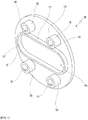
- FIG. 1 is a perspective view of the first module 100 according to an embodiment of the present disclosure and FIGS. 3A and 3B are a front view and a side view of the first module 100 according to the embodiment of the present disclosure, respectively.
- the first module 100 includes a first base 110, a strap boss 120, a first slot 50a, and at least one protrusion accommodation part 130.
- the first base 110 may have a thin plate shape having a circular shape, a polygonal shape, or the like.
- the strap boss 120 may be formed to have a predetermined width at a center portion of the first base 110 and includes the first slot 50a surrounded by an inner circumferential surface of the strap boss 120.
- a strap S may extend to the outside of the pail pack 500 through the first slot 50a.
- the strap boss 120 may include curved portions 121 having a gentle curved shape on both side portions and straight portions 122 formed in a direction connecting the curved portions 121.
- the protrusion accommodation part 130 may be formed in a width direction of the strap boss 120 and may be located at the outer side of the strap boss 120 to be spaced apart from the strap boss 120 at a predetermined interval.
- the protrusion accommodation part 130 includes a bore 131 configured to accommodate a coupling protrusion 230 of the second module 200, and may be variously formed according to a shape of the coupling protrusion.
- the protrusion accommodation part 130 may have a cylindrical shape to be easily coupled and separated.
- the protrusion accommodation part 130 may be greater than or equal to one.
- two pairs of protrusion accommodation parts 130 may be formed above and below the strap boss 120 located at the center portion at predetermined intervals.
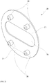
- FIG. 2 is a perspective view of the second module 200 according to the embodiment of the present disclosure
- FIGS. 4A and 4B are a front view and a side view of the second module 200 of the present disclosure, respectively
- FIG. 7 is a use state view of a case in which the strap guide 300 is separated.
- the second module 200 includes a second base 210, a second slot 50b, and at least one coupling protrusion 230.
- the second base 210 may have a thin plate shape having a circular shape, a polygonal shape, or the like.
- the second base 210 may have a shape corresponding to that of the first base 110.
- the second base 210 includes a bent portion 211 having an inclination angle and inclined toward the outside in one side thereof, and the second slot 50b configured to allow the strap S to pass through in a center portion thereof.
- the bent portion 211 may serve as a handle configured to allow the coupled strap guide 300 to be easily separable. Further, the bent portion 211 may be formed at one side of the second base 210 without limitation of a particular location in the second base 210. However, preferably, the bent portion 211 may be formed in a lower portion of the second base 210 so that the strap guide 300 may be easily separated from the pail pack 500.
- the inclination angle of the bent portion 211 is appropriate when it is an angle which allows fingers to easily enter between the first module 100 and the second module 200 to separate the coupled strap guide 300 and allows a force for separating the strap guide 300 to be smoothly transferred, and the inclination angle of the bent portion 211 may preferably be 10° to 20°.
- the coupling protrusion 230 may be located at an outer circumferential portion of the second slot 50b to be spaced apart from the second slot at a predetermined interval, and forms a pair with the protrusion accommodation part 130 of the first module 100 when coupled to the protrusion accommodation part 130.
- the number of coupling protrusions 230 may be one or more and the number of coupling protrusions 230 may be determined according to the number of protrusion accommodation parts 130.
- two pairs of coupling protrusions 230 may be formed above and below the second slot 50b located at the center portion at predetermined intervals.
- a shape of the coupling protrusion 230 may be formed in a shape corresponding to that of the bore 131 of the protrusion accommodation part 130.
- the coupling protrusion 230 may have a cylindrical shape which may be easily coupled and separated, and a corner portion of a cylinder may have a gentle round shape.
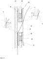
- FIGS. 5A and 5B are a perspective view of a state before the first module 100 and the second module 200 according to the embodiment of the present disclosure are coupled and a perspective view of a state after the first module 100 and the second module 200 according to the embodiment of the present disclosure are coupled, respectively, and FIG. 6 shows a cutaway view of the strap guide 300 coupled to the pail pack 500 according to the embodiment of the present disclosure and a partial enlarged view of an opening edge 51.
- the coupling protrusion 230 of the second module 200 located at a location corresponding to that of the protrusion accommodation part 130 is coupled to the protrusion accommodation part 130 of the first module 100, and a diameter of the coupling protrusion 230 may be formed to have a positive tolerance with respect to a diameter of the bore 131 for strong coupling. Further, since the bore 131 and the coupling protrusion 230 are fit-coupled to each other, shapes thereof may correspond to each other.
- an outer surface of the first base 110, an inner circumferential surface of the strap boss 120, and an outer surface of the second base 210 are connected, and an opening 50 having a single closed surface may be formed.
- a paper tube of the pail pack 500 may become weak to external actions, and when the opening 50 having the single closed surface is formed, since various external actions may be blocked, durability of the pail pack 500 may be improved.
- the strap S may pass through the opening 50 and may be supported by an edge 51 of the opening 50.
- the edge 51 of the opening 50 which comes into contact with the strap S may have a gentle round shape to improve a supporting force of the strap S.
- the strap S since an area in which the strap S and the edge 51 of the opening 50 come into contact with each other increases, the strap S may be more solidly and safely supported.
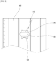
- FIGS. 8A and 8B are a perspective view of the accommodation space part 510 of the pail pack 500 according to the embodiment of the present disclosure and a perspective view of the accommodation space part 510 to which the strap guide 300 is coupled, respectively, and FIG. 9 is a front view of the accommodation space part 510 of the pail pack 500 according to the embodiment.
- the pail pack 500 includes at least two accommodation space parts 510 configured to accommodate at least two strap guides 300.
- the accommodation space part 510 includes a center space part 520 into which the strap boss 120 is fitted, and an upper space part 540 and a lower space part 530 into which the protrusion accommodation parts 130 are fitted, and the strap guide 300 may be fitted into the accommodation space part 510.
- the center space part 520 may be formed according to the shape of the strap boss 120
- the upper space part 540 and the lower space part 530 may be formed according to shapes of the protrusion accommodation part 130.
- a shape in which the protrusion accommodation parts 130 are fitted into the upper space part 540 and the lower space part 530 may be changed according to the number of protrusion accommodation parts 130.
- a width of the strap boss 120 may be greater than or equal to a thickness of the paper tube of the pail pack 500 to protect the tube of the pail pack 500 having a paper tube.
- the paper tube of the pail pack 500 does not exceed the width of the strap boss 120 and is located between the first module 100 and the second module 200 in a state in which the first module 100 and the second module 200 are securely coupled and thus may be protected from an external influence, the durability of the paper tube of the pail pack 500 may be improved.
- the pail pack 500 is formed in a double-layer structure having an inner paper tube 550 and an outer paper tube 560 for enhancing strength.
- the pail pack is a pail pack 500 in which the first module 100 is disposed between the inner paper tube 550 and the outer paper tube 560 of the pail pack 500 and the second module 200 passes through the accommodation space part formed in the outer paper tube from the outer side of the outer paper tube 560 of the pail pack 500 to be coupled to the first module 100.
- the strap S enters the pail pack 500 through the opening 50 of the strap guide 300, and exits to the outside through an opening 50 of a strap guide 300 coupled to another accommodation space part 510 of the pail pack 500 by passing through a bottom part through a gap between the inner paper tube 550 and the outer paper tube 560.
- the pail pack 300 may be efficiently lifted and moved using the strap S in addition to stably protecting the opening and the paper tube of the pail pack 300.
- a first module and a second module are coupled to a pail pack to form an opening of a strap guide having a single closed surface, an opening and a paper tube of pail pack can be safely protected from external actions.
- the opening of the strap guide is processed to be gently round, the strap can be more solidly and safely supported.
- the strap guide in a coupled state can be easily separated by hand.
- the pail pack having an accommodation space part into which the strap guide can be fitted is stable because the strap guide does not rotate and can be engaged without shaking when being lifted or moved.
Landscapes
- Engineering & Computer Science (AREA)
- Mechanical Engineering (AREA)
- Physics & Mathematics (AREA)
- Plasma & Fusion (AREA)
- Details Of Rigid Or Semi-Rigid Containers (AREA)
- Packages (AREA)
Description
- This application claims priority to and the benefit of
Korean Patent Application No. 2018-0024310, filed on Feb. 28, 2018 - The present disclosure relates to a pail pack including a strap guide in which the strap guide is formed as a module coupling type and thus is easily separated from and coupled to the pail pack, improves a strap supporting force, and prevents damage to the pail pack opening.
- A pail pack is a container configured to spirally stack welding wire and then store the wire, and a weight of the pail pack including the stored wire ranges from 100 kg to 500 kg. A cross-sectional surface of the pail pack has a circular shape or a polygonal shape, and there are a manner of moving the pail pack by forming an engaging portion on a side surface of the pail pack to lift the pail pack, and a manner of moving the pail pack by attaching a pallet on a lower end of the pail pack to move the pail pack using a forklift.
- According to a recent technological trend, research on a method of easily performing treatment after the lifespan of a pail pack has ended is actively proceeding, and accordingly, a method of configuring the pail pack to be mainly made of paper is used a lot. When the pail pack is mainly made of paper, since a weight of the pail pack decreases and thus the pail pack is easily moved and stored and is easily recyclable after use, the pail pack is eco-friendly. However, the paper pail pack has various problems such as a strength problem, a moisture resistance problem, and the like due to the paper material.
- An opening can be formed in a side portion of the pail pack to allow the pail pack to be easily moved, and in the case of the paper pail pack, the opening of the pail pack is easily worn and damaged when a process such as lifting or moving the pail pack using a strap is repeated over and over. In order to prevent the above, although there is a method of attaching a fiber reinforcement tape or the like to the opening, the method should be performed by hand and a large amount of time is consumed.
- (Patent Document 1)
Korean Application Patent No. 10-0853527 (August 14, 2008 European Patent Application EP 1 932 612 A1 . - (Patent document 2)
US 2016/255917A1 discloses an ornament assembly, which is an ornament itself, to form a ring hole for a string or a latch through fabric or leather goods. - (Patent document 3)
US 2014/215765A1 discloses a strap guide used in connection with a container having at least one opening for receiving a strap. - The present disclosure is directed to providing a pail pack including a strap guide in which the strap guide is formed as a module coupling type that is easily separated from and coupled to the pail pack, improves a strap supporting force, and prevents damage to a pail pack opening.
- According to an aspect of the present disclosure, the strap guide includes a first module including a first base, a strap boss formed on the first base and including a first slot through which a strap passes, and at least one protrusion accommodation part located at an outer circumferential portion of the strap boss and including a bore; and a second module having a second base, a second slot formed in the second base, and at least one coupling protrusion located at an outer circumferential portion of the second slot and configured to form a pair with the protrusion accommodation part, wherein the first module and the second module are coupled through a pail pack to form an opening having a single closed surface, wherein the pail pack comprises two or more accommodation space parts each configured to accommodate the strap guide, wherein the accommodation space part includes a center space part into which the strap boss is fitted, and an upper space part and a lower space part into which the protrusion accommodation part is fitted, and the strap guide is fitted into the accommodation space part, and wherein the first module is disposed between an inner paper tube and an outer paper tube of the pail pack having the inner paper tube and the outer paper tube, and the second module passes through the accommodation space part formed in the outer paper tube from the outer side of the outer paper tube to be coupled to the first module.
- According to an embodiment, an edge of the opening may have a gentle round shape.
- According to the embodiment, the second base may include a bent portion having an inclination angle and inclined toward the outside in one side thereof.
- According to the embodiment, a diameter of the coupling protrusion may be formed to have a positive tolerance with respect to a diameter of the bore.
- According to the embodiment, the strap boss may include curved portions having a gentle curved shape on both side portions and straight portions formed in a direction connecting the curved portions.
- According to the embodiment, a width of the strap boss may be greater than or equal to a thickness of a paper tube of the pail pack.
- The above and other objects, features and advantages of the present disclosure will become more apparent to those of ordinary skill in the art by describing in detail exemplary embodiments thereof with reference to the accompanying drawings, in which:
-
FIG. 1 is a perspective view of a first module according to an embodiment of the present disclosure; -
FIG. 2 is a perspective view of a second module according to the embodiment of the present disclosure; -
FIGS. 3A and 3B illustrate a front view and a side view of the first module of the present disclosure, respectively; -
FIGS. 4A and 4B illustrate a front view and a side view of the second module of the present disclosure, respectively; -
FIGS. 5A and 5B are a perspective view of a state before the first module and the second module according to the embodiment of the present disclosure are coupled and a perspective view of a state after the first module and the second module according to the embodiment of the present disclosure are coupled, respectively; -
FIG. 6 shows a cutaway view of a strap guide coupled to a pail pack according to the embodiment of the present disclosure and a partial enlarged view of an opening edge; -
FIG. 7 is a use state view of a case in which the strap guide according to the embodiment of the present disclosure is separated; -
FIGS. 8A and 8B are a perspective view of an accommodation space part of the pail pack according to the embodiment of the present disclosure and a perspective view of the accommodation space part to which the strap guide is coupled, respectively; and -
FIG. 9 is a front view of the accommodation space part of the pail pack according to the embodiment. - Hereinafter, the present disclosure will be described in detail with reference to the accompanying drawings. However, the present disclosure may be implemented in various forms, and accordingly, the present disclosure is not limited to the following embodiment. Components not related to the description are omitted in the drawings to clearly describe the present disclosure, and the same reference symbols are used for the same or similar components in the description.
- In the description, in the case in which predetermined components are described as being "connected" to other components, the above case includes a case in which components are indirectly connected to the other components. Further, in the case in which predetermined components are described as "including" predetermined elements, the above case does not exclude other elements but may further include the other elements unless otherwise defined.
- Hereinafter, the embodiment of the present disclosure will be described in detail with reference to the accompanying drawings.
- A
strap guide 300 of the present disclosure is used as a way in which afirst module 100 and asecond module 200 are coupled or separated through anaccommodation space part 510 of apail pack 500. -
FIG. 1 is a perspective view of thefirst module 100 according to an embodiment of the present disclosure andFIGS. 3A and 3B are a front view and a side view of thefirst module 100 according to the embodiment of the present disclosure, respectively. - Referring to
FIGS. 1 and3 , thefirst module 100 includes afirst base 110, astrap boss 120, afirst slot 50a, and at least oneprotrusion accommodation part 130. Thefirst base 110 may have a thin plate shape having a circular shape, a polygonal shape, or the like. - The
strap boss 120 may be formed to have a predetermined width at a center portion of thefirst base 110 and includes thefirst slot 50a surrounded by an inner circumferential surface of thestrap boss 120. A strap S may extend to the outside of thepail pack 500 through thefirst slot 50a. - According to the embodiment, the
strap boss 120 may includecurved portions 121 having a gentle curved shape on both side portions andstraight portions 122 formed in a direction connecting thecurved portions 121. - The
protrusion accommodation part 130 may be formed in a width direction of thestrap boss 120 and may be located at the outer side of thestrap boss 120 to be spaced apart from thestrap boss 120 at a predetermined interval. Theprotrusion accommodation part 130 includes abore 131 configured to accommodate acoupling protrusion 230 of thesecond module 200, and may be variously formed according to a shape of the coupling protrusion. Preferably, theprotrusion accommodation part 130 may have a cylindrical shape to be easily coupled and separated. Theprotrusion accommodation part 130 may be greater than or equal to one. - According to the embodiment, two pairs of
protrusion accommodation parts 130 may be formed above and below thestrap boss 120 located at the center portion at predetermined intervals. -
FIG. 2 is a perspective view of thesecond module 200 according to the embodiment of the present disclosure,FIGS. 4A and 4B are a front view and a side view of thesecond module 200 of the present disclosure, respectively, andFIG. 7 is a use state view of a case in which thestrap guide 300 is separated. - Referring to
FIGS. 2 and4 , thesecond module 200 includes asecond base 210, asecond slot 50b, and at least onecoupling protrusion 230. Thesecond base 210 may have a thin plate shape having a circular shape, a polygonal shape, or the like. Preferably, thesecond base 210 may have a shape corresponding to that of thefirst base 110. - According to the embodiment, the
second base 210 includes abent portion 211 having an inclination angle and inclined toward the outside in one side thereof, and thesecond slot 50b configured to allow the strap S to pass through in a center portion thereof. - Referring to
FIG. 7 , thebent portion 211 may serve as a handle configured to allow the coupledstrap guide 300 to be easily separable. Further, thebent portion 211 may be formed at one side of thesecond base 210 without limitation of a particular location in thesecond base 210. However, preferably, thebent portion 211 may be formed in a lower portion of thesecond base 210 so that thestrap guide 300 may be easily separated from thepail pack 500. The inclination angle of thebent portion 211 is appropriate when it is an angle which allows fingers to easily enter between thefirst module 100 and thesecond module 200 to separate the coupledstrap guide 300 and allows a force for separating thestrap guide 300 to be smoothly transferred, and the inclination angle of thebent portion 211 may preferably be 10° to 20°. - The
coupling protrusion 230 may be located at an outer circumferential portion of thesecond slot 50b to be spaced apart from the second slot at a predetermined interval, and forms a pair with theprotrusion accommodation part 130 of thefirst module 100 when coupled to theprotrusion accommodation part 130. The number ofcoupling protrusions 230 may be one or more and the number ofcoupling protrusions 230 may be determined according to the number ofprotrusion accommodation parts 130. - According to the embodiment, two pairs of
coupling protrusions 230 may be formed above and below thesecond slot 50b located at the center portion at predetermined intervals. A shape of thecoupling protrusion 230 may be formed in a shape corresponding to that of thebore 131 of theprotrusion accommodation part 130. Preferably, thecoupling protrusion 230 may have a cylindrical shape which may be easily coupled and separated, and a corner portion of a cylinder may have a gentle round shape. -
FIGS. 5A and 5B are a perspective view of a state before thefirst module 100 and thesecond module 200 according to the embodiment of the present disclosure are coupled and a perspective view of a state after thefirst module 100 and thesecond module 200 according to the embodiment of the present disclosure are coupled, respectively, andFIG. 6 shows a cutaway view of thestrap guide 300 coupled to thepail pack 500 according to the embodiment of the present disclosure and a partial enlarged view of an openingedge 51. - Referring to
FIGS. 5A, 5B and6 , thecoupling protrusion 230 of thesecond module 200 located at a location corresponding to that of theprotrusion accommodation part 130 is coupled to theprotrusion accommodation part 130 of thefirst module 100, and a diameter of thecoupling protrusion 230 may be formed to have a positive tolerance with respect to a diameter of thebore 131 for strong coupling. Further, since thebore 131 and thecoupling protrusion 230 are fit-coupled to each other, shapes thereof may correspond to each other. - Continuing to refer to
FIGS. 5A, 5B and6 , since thefirst module 100 and thesecond module 200 are coupled to each other, an outer surface of thefirst base 110, an inner circumferential surface of thestrap boss 120, and an outer surface of thesecond base 210 are connected, and anopening 50 having a single closed surface may be formed. - When a process of moving and storing the
pail pack 500 using the strap S is repeated over and over, a paper tube of thepail pack 500 may become weak to external actions, and when theopening 50 having the single closed surface is formed, since various external actions may be blocked, durability of thepail pack 500 may be improved. - Further, the strap S may pass through the
opening 50 and may be supported by anedge 51 of theopening 50. - According to the embodiment, the
edge 51 of theopening 50 which comes into contact with the strap S may have a gentle round shape to improve a supporting force of the strap S. In this case, since an area in which the strap S and theedge 51 of theopening 50 come into contact with each other increases, the strap S may be more solidly and safely supported. -
FIGS. 8A and 8B are a perspective view of theaccommodation space part 510 of thepail pack 500 according to the embodiment of the present disclosure and a perspective view of theaccommodation space part 510 to which thestrap guide 300 is coupled, respectively, andFIG. 9 is a front view of theaccommodation space part 510 of thepail pack 500 according to the embodiment. - Referring to
FIGS. 8A, 8B , and9 , thepail pack 500 includes at least twoaccommodation space parts 510 configured to accommodate at least two strap guides 300. - According to the embodiment, the
accommodation space part 510 includes acenter space part 520 into which thestrap boss 120 is fitted, and anupper space part 540 and alower space part 530 into which theprotrusion accommodation parts 130 are fitted, and thestrap guide 300 may be fitted into theaccommodation space part 510. Thecenter space part 520 may be formed according to the shape of thestrap boss 120, and theupper space part 540 and thelower space part 530 may be formed according to shapes of theprotrusion accommodation part 130. As described above, when thestrap guide 300 is coupled to theaccommodation space part 510 in a fitting manner, thestrap guide 300 and thepail pack 500 are engaged without shaking and do not rotate in a coupled state, and thus are stable. A shape in which theprotrusion accommodation parts 130 are fitted into theupper space part 540 and thelower space part 530 may be changed according to the number ofprotrusion accommodation parts 130. - Referring to
FIGS. 6 and8 , a width of thestrap boss 120 may be greater than or equal to a thickness of the paper tube of thepail pack 500 to protect the tube of thepail pack 500 having a paper tube. In this case, since the paper tube of thepail pack 500 does not exceed the width of thestrap boss 120 and is located between thefirst module 100 and thesecond module 200 in a state in which thefirst module 100 and thesecond module 200 are securely coupled and thus may be protected from an external influence, the durability of the paper tube of thepail pack 500 may be improved. - According to the invention, the
pail pack 500 is formed in a double-layer structure having aninner paper tube 550 and anouter paper tube 560 for enhancing strength. The pail pack is apail pack 500 in which thefirst module 100 is disposed between theinner paper tube 550 and theouter paper tube 560 of thepail pack 500 and thesecond module 200 passes through the accommodation space part formed in the outer paper tube from the outer side of theouter paper tube 560 of thepail pack 500 to be coupled to thefirst module 100. - Further, the strap S enters the
pail pack 500 through theopening 50 of thestrap guide 300, and exits to the outside through anopening 50 of astrap guide 300 coupled to anotheraccommodation space part 510 of thepail pack 500 by passing through a bottom part through a gap between theinner paper tube 550 and theouter paper tube 560. - Accordingly, the
pail pack 300 may be efficiently lifted and moved using the strap S in addition to stably protecting the opening and the paper tube of thepail pack 300. - According to an aspect of the present disclosure, since a first module and a second module are coupled to a pail pack to form an opening of a strap guide having a single closed surface, an opening and a paper tube of pail pack can be safely protected from external actions.
- Further, since the opening of the strap guide is processed to be gently round, the strap can be more solidly and safely supported.
- In addition, due to the second module including a bent portion having an inclination angle and inclined toward the outside, the strap guide in a coupled state can be easily separated by hand.
- In addition, the pail pack having an accommodation space part into which the strap guide can be fitted is stable because the strap guide does not rotate and can be engaged without shaking when being lifted or moved.
- Effects of the present disclosure are not limited to the above-described effects and should be understood to include all effects inferable from the detailed description of the present disclosure or configurations of the present disclosure disclosed in the claims.
- The above description of the present disclosure is exemplary, and it may be understood by those skilled in the art that the present disclosure may be easily modified into other specific forms without changing the technical spirit or essential characteristics. Accordingly, the above-described embodiment should be understood to be wholly exemplary and not limited. For example, elements described as a single type may be implemented to be divided, and elements described as being divided may be implemented as a coupled type.
- The scope of the present invention is shown by the claims which will be described below, and all modifications and modified forms derived from the scope of the claims should be included in the scope of the present disclosure.
Claims (6)
- A pail pack (500) including a strap guide (300) wherein the strap guide (300) comprises:a first module (100) including a first base (110), a strap boss (120) formed on the first base (110) and including a first slot (50a) through which a strap (S) passes, and at least one protrusion accommodation part (130) located at an outer circumferential portion of the strap boss (120) and including a bore (131); anda second module (200) having a second base (210), a second slot (50b) formed in the second base (210), and at least one coupling protrusion (230) located at an outer circumferential portion of the second slot (50b) and configured to form a pair with the protrusion accommodation part (130),wherein the first module (100) and the second module (200) are coupled or separated through an accommodation space part (510) of the pail pack (500) to form an opening (50) having a single closed surface,wherein the pail pack (500) comprises two or more accommodation space parts (510) each configured to accommodate the strap guide (300), wherein the accommodation space part (510) includes a center space part (520) into which the strap boss (120) is fitted, and an upper space part (540) and a lower space part (530) into which the protrusion accommodation part (130) is fitted, and the strap guide (300) is fitted into the accommodation space part (510), characterized in that the first module (100) is disposed between an inner paper tube (550) and an outer paper tube (560) of the pail pack (500) having the inner paper tube (550) and the outer paper tube (560), and the second module (200) passes through the accommodation space part (510) formed in the outer paper tube (560) from the outer side of the outer paper tube (560) to be coupled to the first module (100).
- The pail pack (500) including the strap guide (300) of claim 1, wherein an edge of the opening (50) has a gentle round shape.
- The pail pack (500) including the strap guide (300) of claim 1, wherein the second base (210) includes a bent portion (211) having an inclination angle and inclined toward the outside in one side thereof.
- The pail pack (500) including the strap guide (300) of claim 1, wherein a diameter of the coupling protrusion (230) is formed to have a positive tolerance with respect to a diameter of the bore (131).
- The pail pack (500) including the strap guide (300) of claim 1, wherein the strap boss (120) includes curved portions (121) having a gentle curved shape on both side portions and straight portions (122) formed in a direction connecting the curved portions (121).
- The pail pack (500) including the strap guide (300) of claim 1, wherein a width of the strap boss (120) is greater than or equal to a thickness of a paper tube of the pail pack (500).
Applications Claiming Priority (1)
| Application Number | Priority Date | Filing Date | Title |
|---|---|---|---|
| KR1020180024310A KR102002471B1 (en) | 2018-02-28 | 2018-02-28 | Strap guide and pail pack having the same |
Publications (2)
| Publication Number | Publication Date |
|---|---|
| EP3533552A1 EP3533552A1 (en) | 2019-09-04 |
| EP3533552B1 true EP3533552B1 (en) | 2021-07-14 |
Family
ID=65903879
Family Applications (1)
| Application Number | Title | Priority Date | Filing Date |
|---|---|---|---|
| EP19159278.1A Active EP3533552B1 (en) | 2018-02-28 | 2019-02-26 | Pail pack including a strap guide |
Country Status (4)
| Country | Link |
|---|---|
| US (1) | US10858173B2 (en) |
| EP (1) | EP3533552B1 (en) |
| JP (1) | JP6694089B2 (en) |
| KR (1) | KR102002471B1 (en) |
Families Citing this family (1)
| Publication number | Priority date | Publication date | Assignee | Title |
|---|---|---|---|---|
| US12227342B2 (en) * | 2021-10-04 | 2025-02-18 | Esab Ab | Sidewall support insert |
Family Cites Families (33)
| Publication number | Priority date | Publication date | Assignee | Title |
|---|---|---|---|---|
| US2191291A (en) * | 1936-09-26 | 1940-02-20 | Inland Container Corp | Rim reinforced case and method of forming same |
| US2206314A (en) * | 1939-02-20 | 1940-07-02 | Willy W Werner | Box |
| US3279676A (en) * | 1964-03-09 | 1966-10-18 | Cornish Edward | Carton construction |
| US3372441A (en) * | 1966-12-14 | 1968-03-12 | Illinois Tool Works | Snap-in type grommet |
| US3932010A (en) * | 1975-01-23 | 1976-01-13 | All-Steel, Inc. | Flush pull arrangement for office furniture |
| US4137602A (en) * | 1977-11-11 | 1979-02-06 | Heyman Manufacturing Company | Multipurpose bushing and aperture locking system |
| JPS5695849A (en) * | 1979-12-29 | 1981-08-03 | Sony Corp | Handle |
| AU1806283A (en) * | 1982-08-23 | 1984-03-01 | F F Seeley Nominees Pty Ltd | Carton handle |
| US4843675A (en) * | 1988-09-23 | 1989-07-04 | Panayiotis Diamantis | Two piece removable-curtain grommet |
| US5031268A (en) * | 1990-04-11 | 1991-07-16 | E. I. Du Pont De Nemours And Company | Corner guard assembly |
| US5037027A (en) * | 1990-12-18 | 1991-08-06 | Bradford Company | Tote box construction |
| US5193701A (en) * | 1992-08-13 | 1993-03-16 | Pelikan, Inc. | Box for storing hanging file folders |
| US5295632B1 (en) * | 1992-12-18 | 1998-04-21 | Bradford Co | Tote box with self locking top rail |
| US5520477A (en) * | 1994-06-07 | 1996-05-28 | Seagate, Plastics | Connecting system |
| US5537714A (en) * | 1994-09-01 | 1996-07-23 | Erico International Corp. | Metal stud grommet |
| US5522539A (en) * | 1994-12-16 | 1996-06-04 | Bradford Company | Tote box with block insert locking capability |
| US5462221A (en) * | 1995-01-04 | 1995-10-31 | Bradford Company | Tote box handle |
| US6223390B1 (en) * | 1999-06-16 | 2001-05-01 | Robert J. Lotufo | Carpet sample board handle |
| US6808105B2 (en) * | 2000-12-30 | 2004-10-26 | Dong-Jin Paper Board Box Co., Ltd. | Box for transportation |
| USD469012S1 (en) * | 2001-05-04 | 2003-01-21 | Dong-Jin Paper Board Box Co., Ltd. | Handle of a box |
| US6827217B2 (en) * | 2001-07-11 | 2004-12-07 | Kabushiki Kaisha Kobe Seiko Sho | Welding wire container |
| JP3704574B2 (en) * | 2001-08-31 | 2005-10-12 | 株式会社神戸製鋼所 | Wire box |
| US6619540B1 (en) * | 2002-04-22 | 2003-09-16 | Bradford Company | Snap lock tote box handle and tote box construction |
| US20040007612A1 (en) * | 2002-07-11 | 2004-01-15 | Johanson James E. | Box hand hole reinforcement and method of use |
| JP3675809B1 (en) * | 2004-08-31 | 2005-07-27 | 渡邊 隆久 | Container coupler and prefabricated container using the same |
| US7331506B2 (en) * | 2006-05-31 | 2008-02-19 | Hannspree, Inc. | Carton handle |
| KR100853527B1 (en) | 2006-12-13 | 2008-08-21 | 고려용접봉 주식회사 | Fail pack for welding wire |
| KR101195000B1 (en) * | 2009-06-01 | 2012-10-25 | 허은성 | Packaging pack hand lever |
| US8365912B2 (en) * | 2010-10-21 | 2013-02-05 | Lincoln Global, Inc. | Wire containment structure including container and bag |
| US8967690B2 (en) * | 2012-02-13 | 2015-03-03 | Lincoln Global, Inc. | Strap guide insert |
| US20140077023A1 (en) * | 2012-09-16 | 2014-03-20 | Marc Franklin Foreman | Support strap dispensers and methods |
| KR101485298B1 (en) * | 2014-08-18 | 2015-01-23 | 최훈식 | Ornament assembly |
| US9806510B2 (en) * | 2016-01-20 | 2017-10-31 | Ortronics, Inc. | Cable guide |
-
2018
- 2018-02-28 KR KR1020180024310A patent/KR102002471B1/en active Active
-
2019
- 2019-02-26 EP EP19159278.1A patent/EP3533552B1/en active Active
- 2019-02-28 JP JP2019036473A patent/JP6694089B2/en active Active
- 2019-02-28 US US16/288,696 patent/US10858173B2/en active Active
Non-Patent Citations (1)
| Title |
|---|
| None * |
Also Published As
| Publication number | Publication date |
|---|---|
| EP3533552A1 (en) | 2019-09-04 |
| KR102002471B1 (en) | 2019-10-21 |
| JP6694089B2 (en) | 2020-05-13 |
| JP2019150878A (en) | 2019-09-12 |
| US20190263585A1 (en) | 2019-08-29 |
| US10858173B2 (en) | 2020-12-08 |
Similar Documents
| Publication | Publication Date | Title |
|---|---|---|
| US7950523B2 (en) | Retainer for a welding wire coil | |
| KR100727364B1 (en) | Welded wire package with lifting strap | |
| US20060283073A1 (en) | Frame for lineguide and fish pole | |
| US10899495B2 (en) | Storage unit for welding wire | |
| EP3533552B1 (en) | Pail pack including a strap guide | |
| US9265307B2 (en) | Strap guide insert | |
| EP3604158B1 (en) | Handle, and container with handle | |
| EP2703318B1 (en) | Pulp molded cushioning material and packing case provided with same | |
| KR102131571B1 (en) | Rack apparatus for sack | |
| JP5210142B2 (en) | Gear storage tray and storage body | |
| JP7350259B2 (en) | roll storage container | |
| KR101084622B1 (en) | Dye Bobbin | |
| JP7388695B2 (en) | roll storage container | |
| JP7123382B2 (en) | container | |
| EP3565763B1 (en) | Container | |
| KR102359169B1 (en) | Carrying tool for roll type electric wire | |
| KR200434464Y1 (en) | Fail pack for welding wire | |
| CN216888204U (en) | Egg tray assembly | |
| CN211317088U (en) | Guided missile case convenient to transport | |
| CN212149629U (en) | Lifting handle | |
| JP5396990B2 (en) | Packing method | |
| KR101583757B1 (en) | Drum protection ring and drum including the same | |
| KR200491692Y1 (en) | Hanger delivery box | |
| HK1082717A (en) | Welding wire package with lifting strap | |
| KR200188245Y1 (en) | Cover for egg container tray |
Legal Events
| Date | Code | Title | Description |
|---|---|---|---|
| PUAI | Public reference made under article 153(3) epc to a published international application that has entered the european phase |
Free format text: ORIGINAL CODE: 0009012 |
|
| STAA | Information on the status of an ep patent application or granted ep patent |
Free format text: STATUS: REQUEST FOR EXAMINATION WAS MADE |
|
| 17P | Request for examination filed |
Effective date: 20190325 |
|
| AK | Designated contracting states |
Kind code of ref document: A1 Designated state(s): AL AT BE BG CH CY CZ DE DK EE ES FI FR GB GR HR HU IE IS IT LI LT LU LV MC MK MT NL NO PL PT RO RS SE SI SK SM TR |
|
| AX | Request for extension of the european patent |
Extension state: BA ME |
|
| RBV | Designated contracting states (corrected) |
Designated state(s): AL AT BE BG CH CY CZ DE DK EE ES FI FR GB GR HR HU IE IS IT LI LT LU LV MC MK MT NL NO PL PT RO RS SE SI SK SM TR |
|
| GRAP | Despatch of communication of intention to grant a patent |
Free format text: ORIGINAL CODE: EPIDOSNIGR1 |
|
| STAA | Information on the status of an ep patent application or granted ep patent |
Free format text: STATUS: GRANT OF PATENT IS INTENDED |
|
| INTG | Intention to grant announced |
Effective date: 20201211 |
|
| GRAS | Grant fee paid |
Free format text: ORIGINAL CODE: EPIDOSNIGR3 |
|
| GRAJ | Information related to disapproval of communication of intention to grant by the applicant or resumption of examination proceedings by the epo deleted |
Free format text: ORIGINAL CODE: EPIDOSDIGR1 |
|
| GRAL | Information related to payment of fee for publishing/printing deleted |
Free format text: ORIGINAL CODE: EPIDOSDIGR3 |
|
| STAA | Information on the status of an ep patent application or granted ep patent |
Free format text: STATUS: REQUEST FOR EXAMINATION WAS MADE |
|
| GRAP | Despatch of communication of intention to grant a patent |
Free format text: ORIGINAL CODE: EPIDOSNIGR1 |
|
| STAA | Information on the status of an ep patent application or granted ep patent |
Free format text: STATUS: GRANT OF PATENT IS INTENDED |
|
| INTC | Intention to grant announced (deleted) | ||
| INTG | Intention to grant announced |
Effective date: 20210504 |
|
| GRAA | (expected) grant |
Free format text: ORIGINAL CODE: 0009210 |
|
| STAA | Information on the status of an ep patent application or granted ep patent |
Free format text: STATUS: THE PATENT HAS BEEN GRANTED |
|
| AK | Designated contracting states |
Kind code of ref document: B1 Designated state(s): AL AT BE BG CH CY CZ DE DK EE ES FI FR GB GR HR HU IE IS IT LI LT LU LV MC MK MT NL NO PL PT RO RS SE SI SK SM TR |
|
| REG | Reference to a national code |
Ref country code: GB Ref legal event code: FG4D |
|
| REG | Reference to a national code |
Ref country code: IE Ref legal event code: FG4D |
|
| REG | Reference to a national code |
Ref country code: DE Ref legal event code: R096 Ref document number: 602019006017 Country of ref document: DE |
|
| REG | Reference to a national code |
Ref country code: AT Ref legal event code: REF Ref document number: 1410261 Country of ref document: AT Kind code of ref document: T Effective date: 20210815 |
|
| REG | Reference to a national code |
Ref country code: LT Ref legal event code: MG9D |
|
| REG | Reference to a national code |
Ref country code: NL Ref legal event code: MP Effective date: 20210714 |
|
| REG | Reference to a national code |
Ref country code: AT Ref legal event code: MK05 Ref document number: 1410261 Country of ref document: AT Kind code of ref document: T Effective date: 20210714 |
|
| PG25 | Lapsed in a contracting state [announced via postgrant information from national office to epo] |
Ref country code: ES Free format text: LAPSE BECAUSE OF FAILURE TO SUBMIT A TRANSLATION OF THE DESCRIPTION OR TO PAY THE FEE WITHIN THE PRESCRIBED TIME-LIMIT Effective date: 20210714 Ref country code: FI Free format text: LAPSE BECAUSE OF FAILURE TO SUBMIT A TRANSLATION OF THE DESCRIPTION OR TO PAY THE FEE WITHIN THE PRESCRIBED TIME-LIMIT Effective date: 20210714 Ref country code: RS Free format text: LAPSE BECAUSE OF FAILURE TO SUBMIT A TRANSLATION OF THE DESCRIPTION OR TO PAY THE FEE WITHIN THE PRESCRIBED TIME-LIMIT Effective date: 20210714 Ref country code: SE Free format text: LAPSE BECAUSE OF FAILURE TO SUBMIT A TRANSLATION OF THE DESCRIPTION OR TO PAY THE FEE WITHIN THE PRESCRIBED TIME-LIMIT Effective date: 20210714 Ref country code: PT Free format text: LAPSE BECAUSE OF FAILURE TO SUBMIT A TRANSLATION OF THE DESCRIPTION OR TO PAY THE FEE WITHIN THE PRESCRIBED TIME-LIMIT Effective date: 20211115 Ref country code: NL Free format text: LAPSE BECAUSE OF FAILURE TO SUBMIT A TRANSLATION OF THE DESCRIPTION OR TO PAY THE FEE WITHIN THE PRESCRIBED TIME-LIMIT Effective date: 20210714 Ref country code: NO Free format text: LAPSE BECAUSE OF FAILURE TO SUBMIT A TRANSLATION OF THE DESCRIPTION OR TO PAY THE FEE WITHIN THE PRESCRIBED TIME-LIMIT Effective date: 20211014 Ref country code: HR Free format text: LAPSE BECAUSE OF FAILURE TO SUBMIT A TRANSLATION OF THE DESCRIPTION OR TO PAY THE FEE WITHIN THE PRESCRIBED TIME-LIMIT Effective date: 20210714 Ref country code: AT Free format text: LAPSE BECAUSE OF FAILURE TO SUBMIT A TRANSLATION OF THE DESCRIPTION OR TO PAY THE FEE WITHIN THE PRESCRIBED TIME-LIMIT Effective date: 20210714 Ref country code: BG Free format text: LAPSE BECAUSE OF FAILURE TO SUBMIT A TRANSLATION OF THE DESCRIPTION OR TO PAY THE FEE WITHIN THE PRESCRIBED TIME-LIMIT Effective date: 20211014 Ref country code: LT Free format text: LAPSE BECAUSE OF FAILURE TO SUBMIT A TRANSLATION OF THE DESCRIPTION OR TO PAY THE FEE WITHIN THE PRESCRIBED TIME-LIMIT Effective date: 20210714 |
|
| PG25 | Lapsed in a contracting state [announced via postgrant information from national office to epo] |
Ref country code: PL Free format text: LAPSE BECAUSE OF FAILURE TO SUBMIT A TRANSLATION OF THE DESCRIPTION OR TO PAY THE FEE WITHIN THE PRESCRIBED TIME-LIMIT Effective date: 20210714 Ref country code: LV Free format text: LAPSE BECAUSE OF FAILURE TO SUBMIT A TRANSLATION OF THE DESCRIPTION OR TO PAY THE FEE WITHIN THE PRESCRIBED TIME-LIMIT Effective date: 20210714 Ref country code: GR Free format text: LAPSE BECAUSE OF FAILURE TO SUBMIT A TRANSLATION OF THE DESCRIPTION OR TO PAY THE FEE WITHIN THE PRESCRIBED TIME-LIMIT Effective date: 20211015 |
|
| REG | Reference to a national code |
Ref country code: DE Ref legal event code: R097 Ref document number: 602019006017 Country of ref document: DE |
|
| PG25 | Lapsed in a contracting state [announced via postgrant information from national office to epo] |
Ref country code: DK Free format text: LAPSE BECAUSE OF FAILURE TO SUBMIT A TRANSLATION OF THE DESCRIPTION OR TO PAY THE FEE WITHIN THE PRESCRIBED TIME-LIMIT Effective date: 20210714 |
|
| PLBE | No opposition filed within time limit |
Free format text: ORIGINAL CODE: 0009261 |
|
| STAA | Information on the status of an ep patent application or granted ep patent |
Free format text: STATUS: NO OPPOSITION FILED WITHIN TIME LIMIT |
|
| PG25 | Lapsed in a contracting state [announced via postgrant information from national office to epo] |
Ref country code: SM Free format text: LAPSE BECAUSE OF FAILURE TO SUBMIT A TRANSLATION OF THE DESCRIPTION OR TO PAY THE FEE WITHIN THE PRESCRIBED TIME-LIMIT Effective date: 20210714 Ref country code: SK Free format text: LAPSE BECAUSE OF FAILURE TO SUBMIT A TRANSLATION OF THE DESCRIPTION OR TO PAY THE FEE WITHIN THE PRESCRIBED TIME-LIMIT Effective date: 20210714 Ref country code: RO Free format text: LAPSE BECAUSE OF FAILURE TO SUBMIT A TRANSLATION OF THE DESCRIPTION OR TO PAY THE FEE WITHIN THE PRESCRIBED TIME-LIMIT Effective date: 20210714 Ref country code: EE Free format text: LAPSE BECAUSE OF FAILURE TO SUBMIT A TRANSLATION OF THE DESCRIPTION OR TO PAY THE FEE WITHIN THE PRESCRIBED TIME-LIMIT Effective date: 20210714 Ref country code: CZ Free format text: LAPSE BECAUSE OF FAILURE TO SUBMIT A TRANSLATION OF THE DESCRIPTION OR TO PAY THE FEE WITHIN THE PRESCRIBED TIME-LIMIT Effective date: 20210714 Ref country code: AL Free format text: LAPSE BECAUSE OF FAILURE TO SUBMIT A TRANSLATION OF THE DESCRIPTION OR TO PAY THE FEE WITHIN THE PRESCRIBED TIME-LIMIT Effective date: 20210714 |
|
| 26N | No opposition filed |
Effective date: 20220419 |
|
| PG25 | Lapsed in a contracting state [announced via postgrant information from national office to epo] |
Ref country code: IT Free format text: LAPSE BECAUSE OF FAILURE TO SUBMIT A TRANSLATION OF THE DESCRIPTION OR TO PAY THE FEE WITHIN THE PRESCRIBED TIME-LIMIT Effective date: 20210714 |
|
| PG25 | Lapsed in a contracting state [announced via postgrant information from national office to epo] |
Ref country code: MC Free format text: LAPSE BECAUSE OF FAILURE TO SUBMIT A TRANSLATION OF THE DESCRIPTION OR TO PAY THE FEE WITHIN THE PRESCRIBED TIME-LIMIT Effective date: 20210714 |
|
| REG | Reference to a national code |
Ref country code: CH Ref legal event code: PL |
|
| REG | Reference to a national code |
Ref country code: BE Ref legal event code: MM Effective date: 20220228 |
|
| PG25 | Lapsed in a contracting state [announced via postgrant information from national office to epo] |
Ref country code: LU Free format text: LAPSE BECAUSE OF NON-PAYMENT OF DUE FEES Effective date: 20220226 |
|
| PG25 | Lapsed in a contracting state [announced via postgrant information from national office to epo] |
Ref country code: FR Free format text: LAPSE BECAUSE OF NON-PAYMENT OF DUE FEES Effective date: 20220228 |
|
| PG25 | Lapsed in a contracting state [announced via postgrant information from national office to epo] |
Ref country code: LI Free format text: LAPSE BECAUSE OF NON-PAYMENT OF DUE FEES Effective date: 20220228 Ref country code: IE Free format text: LAPSE BECAUSE OF NON-PAYMENT OF DUE FEES Effective date: 20220226 Ref country code: CH Free format text: LAPSE BECAUSE OF NON-PAYMENT OF DUE FEES Effective date: 20220228 |
|
| PG25 | Lapsed in a contracting state [announced via postgrant information from national office to epo] |
Ref country code: BE Free format text: LAPSE BECAUSE OF NON-PAYMENT OF DUE FEES Effective date: 20220228 |
|
| REG | Reference to a national code |
Ref country code: DE Ref legal event code: R081 Ref document number: 602019006017 Country of ref document: DE Owner name: KISWEL LTD., KR Free format text: FORMER OWNER: KISWEL LTD., BUSAN, KR |
|
| REG | Reference to a national code |
Ref country code: DE Ref legal event code: R081 Ref document number: 602019006017 Country of ref document: DE Owner name: KISWEL LTD., KR Free format text: FORMER OWNER: KISWEL HOLDINGS LTD., BUSAN, KR |
|
| PG25 | Lapsed in a contracting state [announced via postgrant information from national office to epo] |
Ref country code: MK Free format text: LAPSE BECAUSE OF FAILURE TO SUBMIT A TRANSLATION OF THE DESCRIPTION OR TO PAY THE FEE WITHIN THE PRESCRIBED TIME-LIMIT Effective date: 20210714 Ref country code: CY Free format text: LAPSE BECAUSE OF FAILURE TO SUBMIT A TRANSLATION OF THE DESCRIPTION OR TO PAY THE FEE WITHIN THE PRESCRIBED TIME-LIMIT Effective date: 20210714 |
|
| PG25 | Lapsed in a contracting state [announced via postgrant information from national office to epo] |
Ref country code: HU Free format text: LAPSE BECAUSE OF FAILURE TO SUBMIT A TRANSLATION OF THE DESCRIPTION OR TO PAY THE FEE WITHIN THE PRESCRIBED TIME-LIMIT; INVALID AB INITIO Effective date: 20190226 |
|
| PG25 | Lapsed in a contracting state [announced via postgrant information from national office to epo] |
Ref country code: TR Free format text: LAPSE BECAUSE OF FAILURE TO SUBMIT A TRANSLATION OF THE DESCRIPTION OR TO PAY THE FEE WITHIN THE PRESCRIBED TIME-LIMIT Effective date: 20210714 |
|
| PG25 | Lapsed in a contracting state [announced via postgrant information from national office to epo] |
Ref country code: MT Free format text: LAPSE BECAUSE OF FAILURE TO SUBMIT A TRANSLATION OF THE DESCRIPTION OR TO PAY THE FEE WITHIN THE PRESCRIBED TIME-LIMIT Effective date: 20210714 |
|
| PGFP | Annual fee paid to national office [announced via postgrant information from national office to epo] |
Ref country code: GB Payment date: 20260108 Year of fee payment: 8 |
|
| PGFP | Annual fee paid to national office [announced via postgrant information from national office to epo] |
Ref country code: DE Payment date: 20260105 Year of fee payment: 8 |