EP3533521A1 - Pipette tip and pipette system - Google Patents
Pipette tip and pipette system Download PDFInfo
- Publication number
- EP3533521A1 EP3533521A1 EP16919641.7A EP16919641A EP3533521A1 EP 3533521 A1 EP3533521 A1 EP 3533521A1 EP 16919641 A EP16919641 A EP 16919641A EP 3533521 A1 EP3533521 A1 EP 3533521A1
- Authority
- EP
- European Patent Office
- Prior art keywords
- capillary tube
- pipette tip
- sample
- pipette
- adapter
- Prior art date
- Legal status (The legal status is an assumption and is not a legal conclusion. Google has not performed a legal analysis and makes no representation as to the accuracy of the status listed.)
- Granted
Links
- 239000003153 chemical reaction reagent Substances 0.000 claims description 8
- 239000007788 liquid Substances 0.000 description 21
- 239000008280 blood Substances 0.000 description 14
- 210000004369 blood Anatomy 0.000 description 14
- 238000012360 testing method Methods 0.000 description 10
- 238000000034 method Methods 0.000 description 7
- 238000013461 design Methods 0.000 description 5
- 238000012546 transfer Methods 0.000 description 4
- 238000007792 addition Methods 0.000 description 3
- 239000000463 material Substances 0.000 description 3
- 238000004458 analytical method Methods 0.000 description 2
- 239000011521 glass Substances 0.000 description 2
- 238000005259 measurement Methods 0.000 description 2
- 239000000203 mixture Substances 0.000 description 2
- 238000012986 modification Methods 0.000 description 2
- 230000004048 modification Effects 0.000 description 2
- 238000006467 substitution reaction Methods 0.000 description 2
- 210000004204 blood vessel Anatomy 0.000 description 1
- 230000000694 effects Effects 0.000 description 1
- 238000003018 immunoassay Methods 0.000 description 1
- 238000004519 manufacturing process Methods 0.000 description 1
- 102000004169 proteins and genes Human genes 0.000 description 1
- 108090000623 proteins and genes Proteins 0.000 description 1
- 230000009430 psychological distress Effects 0.000 description 1
- 239000010409 thin film Substances 0.000 description 1
Images


Classifications
-
- B—PERFORMING OPERATIONS; TRANSPORTING
- B01—PHYSICAL OR CHEMICAL PROCESSES OR APPARATUS IN GENERAL
- B01L—CHEMICAL OR PHYSICAL LABORATORY APPARATUS FOR GENERAL USE
- B01L3/00—Containers or dishes for laboratory use, e.g. laboratory glassware; Droppers
- B01L3/02—Burettes; Pipettes
- B01L3/0275—Interchangeable or disposable dispensing tips
-
- B—PERFORMING OPERATIONS; TRANSPORTING
- B01—PHYSICAL OR CHEMICAL PROCESSES OR APPARATUS IN GENERAL
- B01L—CHEMICAL OR PHYSICAL LABORATORY APPARATUS FOR GENERAL USE
- B01L3/00—Containers or dishes for laboratory use, e.g. laboratory glassware; Droppers
- B01L3/02—Burettes; Pipettes
- B01L3/021—Pipettes, i.e. with only one conduit for withdrawing and redistributing liquids
- B01L3/0217—Pipettes, i.e. with only one conduit for withdrawing and redistributing liquids of the plunger pump type
- B01L3/022—Capillary pipettes, i.e. having very small bore
-
- G—PHYSICS
- G01—MEASURING; TESTING
- G01N—INVESTIGATING OR ANALYSING MATERIALS BY DETERMINING THEIR CHEMICAL OR PHYSICAL PROPERTIES
- G01N35/00—Automatic analysis not limited to methods or materials provided for in any single one of groups G01N1/00 - G01N33/00; Handling materials therefor
- G01N35/10—Devices for transferring samples or any liquids to, in, or from, the analysis apparatus, e.g. suction devices, injection devices
-
- B—PERFORMING OPERATIONS; TRANSPORTING
- B01—PHYSICAL OR CHEMICAL PROCESSES OR APPARATUS IN GENERAL
- B01L—CHEMICAL OR PHYSICAL LABORATORY APPARATUS FOR GENERAL USE
- B01L2400/00—Moving or stopping fluids
- B01L2400/04—Moving fluids with specific forces or mechanical means
- B01L2400/0403—Moving fluids with specific forces or mechanical means specific forces
- B01L2400/0406—Moving fluids with specific forces or mechanical means specific forces capillary forces
-
- B—PERFORMING OPERATIONS; TRANSPORTING
- B01—PHYSICAL OR CHEMICAL PROCESSES OR APPARATUS IN GENERAL
- B01L—CHEMICAL OR PHYSICAL LABORATORY APPARATUS FOR GENERAL USE
- B01L2400/00—Moving or stopping fluids
- B01L2400/04—Moving fluids with specific forces or mechanical means
- B01L2400/0475—Moving fluids with specific forces or mechanical means specific mechanical means and fluid pressure
- B01L2400/0487—Moving fluids with specific forces or mechanical means specific mechanical means and fluid pressure fluid pressure, pneumatics
Definitions
- the present invention relates generally to a pipette tip for facilitating collection of a fixed volume of a sample, and a pipette system including the same. More particularly, the present invention relates to a pipette tip capable of collecting a relatively large-volume liquid sample using a capillary tube, and a pipette system capable of collecting, transferring, and dispensing of the liquid sample using the pipette tip.
- pipettes are thin tubes of glass or plastic used for measuring and dispensing liquids.
- the pipettes come in various designs depending on application purposes, such as a mess pipette, a hole pipette, a dropping pipette, a Pasteur pipette, an automatic pipette, and the like.
- pipette tips are used to collect, mix, and dispense a fixed volume of a sample.
- an experimenter manually tests a sample with a pipette that has a volume suitable for collecting a fixed volume of the sample to be collected.
- various automated instruments which make such a test easy and make it possible to simultaneously test many samples, have been developed and popularized.
- An automated instrument refers to a clinical test instrument that can automatically process (dispense and pretreat) a sample more than once through an onboard software. Such an automated instrument is disadvantageous in that several tens of times more samples are required than a required volume of a sample to be collected for measurement.
- an automated instrument for testing and measuring proteins present in human blood a method of collecting 5 mL or more of venous blood for a test and storing the venous blood to be tested in a predetermined tube is used.
- the volume of blood actually used for measurement practice is 10 ⁇ l.
- such an automated instrument requires that several milliliters of blood be contained in a blood tube, and if not, automatic collection is impossible.
- 10 ⁇ l of blood can be collected by using capillary blood from a fingertip.
- infants and children or patients who have deep blood vessels and are difficult to collect blood therefrom may suffer psychological distress of blood collection and difficulty of blood collection itself.
- Patent Document 1 Korean Patent No. 10-1510823 (registered on April. 13, 2015 )
- an objective of the present invention is to provide a pipette tip capable of collecting a small fixed volume of a sample even without using a pipette, and a pipette system capable of conveniently performing pretreatment of mixing the liquid sample with a pretreatment solution by using the pipette tip.
- a pipette tip including: a sample collection part having a capillary tube formed in a longitudinal direction for introducing samples; and a barrel body having a sample storage chamber which communicates with the capillary tube through a stepped portion and stores the samples.
- the stepped portion should have an inclination angle with the capillary tube of equal to or greater than 45°.
- the capillary tube may include: a first capillary tube; and a second capillary tube having a different cross-sectional area from that of the first capillary tube.
- the capillary tube may have a cross section of an elongated circle or of a cross.
- a pipette system including: a pipette tip including a sample collection part having a capillary tube formed in a longitudinal direction for introducing samples, and a barrel body having a sample storage chamber that communicates with the capillary tube through a stepped portion and stores the sample; and a handler configured to control pressure inside the pipette tip by a pressure source that is secured to an end of the barrel body and is controlled by an electrical control signal.
- the handler may include: an adapter having a flow path formed therethrough, and fitted to an opening of the barrel body; and a pump controlling the pressure inside the pipette tip through the adapter by the electrical control signal input from outside.
- the handler may include: a guide part guiding movement of the adapter between a site where the pipette tip is located and a site where a reagent cartridge is located; a driving part generating a driving force for controlling the movement of the adapter along the guide part; and a control unit generating an electrical control signal for controlling operation of the pump and the driving part.
- a pipette tip includes a sample collection part having a capillary tube and a barrel body having a storage chamber that extends from a rear end of the capillary tube through a stepped portion. Therefore, the present invention can collect a fixed volume of a liquid sample using a capillary tube that is designed to have a predetermined volume. This makes it possible to perform an accurate test for a small-volume sample such as capillary blood.
- a pipette tip according to the related art itself does not have a function of aspirating a predetermined volume of a sample
- a method of setting a volume of the sample to be collected by using a volume setting function of a pipette is used.
- the present invention it is possible for a pipette tip itself to collect a predetermined volume of a liquid sample having a predetermined volume without using a pipette. Therefore, the present invention can be utilized in automated analyzers, thus enabling an automated analysis using a small-volume sample such as capillary blood.
- a pipette system can conveniently mix a sample with a pretreatment solution and dispense the sample, by using a pipette tip capable of collecting a fixed volume of a sample using capillary action.
- first, second, etc. may be used herein to describe various elements, these elements should not be limited by these terms. These terms are only used to distinguish one element, from another element. For instance, a first element discussed below could be termed a second element without departing from the teachings of the present invention. Similarly, the second element could also be termed the first element.
- a pipette tip 100 includes: a sample collection part 110 in which a capillary 111 is formed in a longitudinal direction for introducing samples; and a barrel body 120 having a sample storage chamber 122 that communicates with the capillary tube 111 through a stepped portion 121 and in which the sample is stored.
- the sample collection part 110 and the barrel body 120 are integrally formed with each other and may be made of glass or plastic, but are not limited to a specific material. However, it is preferable that a material having a high rigidity be used so as not to cause deformation due to an external force.
- a hydrophilic material may be used or a hydrophilic thin film may be coated on the inner circumferential surface of the capillary tube 111.
- the capillary tube 111 is formed through the sample collection part 110 along the longitudinal direction of the sample collecting part and stores the sample by capillary action.
- a collection volume of about 5 ⁇ l to 100 ⁇ l may be possible.
- the size (diameter) of the capillary tube 111 may be determined within a range in which the sample can be collected by capillary action, preferably within about 0.5 mm to 1.5 mm.
- the barrel body 120 is integrally formed with the sample collection part 110 and has the sample storage chamber 122 communicating with the rear end of the capillary tube 111.
- the sample storage chamber 122 extends from the rear end of the capillary tube 111 through the stepped portion 121 and is larger in diameter than the capillary tube 111.
- an inclination angle of the stepped portion 121 with respect to the capillary 111 is a right angle.
- the inclination angle ⁇ is equal to or greater than 45°, a liquid sample collected by capillary action is only filled up to the capillary tube 111.
- the inclination angle ⁇ may be equal to or greater than 90°.
- the sample storage chamber 122 is formed through the center of the barrel body 120 and provides a space in which the sample is mixed with a pretreatment solution. It is preferable that the sample storage chamber 122 have a conical inclined surface that is inclined upward from the stepped portion 121.
- the sample storage chamber 122 has a wide rear opening.
- the rear opening of the sample storage chamber may be assembled with an automated instrument having a tapered surface that corresponds to the opening by luer lock fitting. It is preferable that the sample storage chamber 122 have an annular engagement groove 123 that is formed in the inner surface thereof so as to be fitted to a protrusion protruding from the tapered surface of the automated instrument.
- the pipette tip 100 configured as described above is configured such that a correct collection volume thereof is determined by the volume of the capillary tube 111 of the sample collection part 110. That is, the volume of the capillary 111 is determined by the cross-sectional area and a length L of the capillary tube 111, and a collected sample fills the capillary tube 111 below the stepped portion 121 by capillary action.
- the cross-sectional shape of the capillary tube may be variously modified in consideration of the collection volume of the pipette tip. For example, in order to increase the collection volume of the pipette tip, it is required to increase the length L of the sample collection part. However, in the present invention, the cross-sectional area of the capillary tube may be increased for a large collection volume.
- FIGS. 2a to 2f are views showing various embodiments of flat cross-section of the capillary tube of the pipette tip according to the present invention.
- a capillary tube 111a in FIG. 2a has a circular-shaped cross-section
- a capillary tube 111b in FIG. 2b has a long hole-shaped cross-section
- a capillary tube 111c in FIG. 2c has a cross-shaped cross-section
- a capillary tube 111d in FIG. 2d has a star-shaped cross-section formed by multiple bar-shaped holes intersecting with each other at positions circumferentially spaced out at regular angular intervals.
- a size d (diameter or width) of each of the capillary tubes 111a, 111b, 111c, and 111d be determined within a range in which capillary action can be affected, for example, about 0.5 mm to 1.5 mm.
- FIG. 2e shows that a capillary tube 111e has an annular-shaped cross-section that is defined between a core 112 placed in a circular hole and the wall of the circular hole.
- a diameter d1 of the capillary tube 111e itself is larger than that of the capillary tubes of the embodiments in FIGS. 2a, 2b, 2c, and 2d .
- an effective size d due to the size of the core 112 is determined within a range of 0.5 mm to 1.5 mm in which capillary action can be affected. This results in an increase in effective cross-sectional area, thus ensuring that collection of a large-volume sample can be achieved.
- FIG. 2f shows that a capillary tube 111e has a rectangular ring-shaped cross-section that is defined between a core 113 placed in a rectangular hole and the wall of the rectangular hole.
- FIG. 3 is an enlarged sectional view showing a sample collection part of a pipette tip according to another embodiment of the present invention.
- capillary tubes 211 and 212 are formed in a sample collection part 210 of the pipette tip according to the present invention are comprised of a first capillary tube 211 formed in a front opening, and a second capillary tube 212 having a smaller cross-sectional area than the first capillary tube 211 and communicating therewith.
- the size (diameter or width) of the second capillary tube 212 be determined to be equal to or less than 1.5 mm such that capillary action can be affected. It is more preferable that the first capillary tube 211 and the second capillary tube 212 communicates with each other through a stepped portion 211a.
- the capillary tube configured as described above is comprised of a first capillary tube section A and a second capillary tube section B, and the respective sections communicate with each other through the stepped portion. This ensures that it is possible to facilitate the design of a large-volume pipette tip or design of a pipette tip having various collection volumes, and the manufacture thereof.
- a pipette tip for collecting a large-volume liquid sample requires that the length of the capillary tube 111 be longer in proportion to the design volume. This may cause a problem in that, when the pipette tip is applied to an automated analyzer, occurrence of interference due to the length of the pipette tip has to be considered.
- the pipette tip 200 for collecting a large-volume liquid sample (50 ⁇ l ⁇ ) is designed such that the pipette tip is divided into at least two sections depending on the collection volume, and one of the sections formed in the front opening has a predetermined length L2 with a large diameter. This ensures that the design of a required collection volume can be achieved while limiting a total length L1 of the capillary tubes 211 and 212 to equal to or less than a predetermined length.
- FIGS. 4a to 4f are views showing a method of using the pipette tip according to the present invention.
- the sample 10 is collected with the pipette tip 100. At this time, a fixed volume of the sample 10 is accurately collected in the capillary tube of the sample collection part 110 by capillary action.
- the pipette tip 100 having the sample 10 collected therein is mounted on a handler for controlling pressure.
- the handler includes an adapter 310 having a flow path formed therethrough and assembled with the pipette tip 100, and a pump configured to generate a positive pressure or negative pressure acting on the pipette tip 100 through the adapter 310.
- the adapter 310 is a hollow tube and is fitted to an upper portion of the pipette tip 100, and is connected to the pump 320 through a pipe.
- the sample in the sample collection part 110 of the pipette tip 100 is introduced into the barrel body 120 by the negative pressure generated by the handler and stored therein.
- the pipette tip 100 mounted on the handler is transferred into a pretreatment solution 20, and the sample 10 and the pretreatment solution 20 are mixed to obtain a mixed liquid 30.
- discharge of the sample 10 in the pipette tip 100 upon transfer is made by the positive pressure generated by the pump 320.
- the mixed liquid 30 is sucked up into the pipette tip 100, and the sucked mixed liquid 30 can be dispensed at a desired position. At this time, the mixed liquid 30 is sucked up into the pipette tip 100 by the negative pressure generated by the pump 320.
- FIG. 5 is a view showing a configuration of a pipette system according to the present invention.
- a pipette system includes: a guide part for guiding movement of the adapter 310; a driving part for generating a driving force for controlling the movement of the adapter 310 along the guide part; and a control unit for controlling operations of a pump and the driving part.
- the adapter 310 is a module type integrally formed with the pump 320.
- the adapter 310 is provided at a lower surface of the pump 320 such that the pump is moved together with the adapter 310.
- the adapter may be connected to the pump by a flexible hose such that only the adapter can be moved for operation.
- the guide part guides movement of the adapter 310 between a pipette tip site where multiple pipette tips 100 each having a fixed volume of a liquid sample collected therein are located, and a reagent cartridge site where a reagent cartridge 21 is located.
- the guide part is comprised of a vertical ball screw 411, a movable frame 410 guided by the vertical ball screw 411 so as to be moved vertically, and a horizontal ball screw 412 provided horizontally at the movable frame 410 to guide a horizontal movement of the pump 320.
- the pipette tips 100 are stored in a rack 401 provided at a designated position in a state of having the fixed volumes of the liquid samples collected therein, and the reagent cartridge 21 is provided at a side of a transfer device 500.
- the vertical ball screw 411 and the horizontal ball screw 412 are provided to be rotatable by well-known bearings.
- the vertical and horizontal ball screws include a first driving motor 413 and a second driving motor 414 for rotating the ball screws, respectively.
- the control unit 420 controls operations of the pump 320 and the first and second driving motors 413 and 414. In detail, the control unit 420 controls the first driving motor 413 and the second driving motor 413 to control the movement position of the adapter 310. Also, the control unit moves a pipette tip 100 having a liquid sample collected therein to the reagent cartridge 21 to allow the liquid sample to be mixed with a pretreatment solution of the reagent cartridge 21 or dispensed.
- control unit 420 controls the pump 320 such that an appropriate pressure acts on the pipette tip 100 in the process of moving the pipette tip 100 and mixing or dispensing the liquid sample therein, thus preventing leakage of the liquid sample that may occur in the process of moving the pipette tip, and facilitating mixing of the liquid sample with the pretreatment solution or dispensing thereof.
- the reagent cartridge 21 in which the liquid sample is mixed with the pretreatment solution or dispensed is transferred to a test unit 600 by the transfer device 500 and subjected to a test.
- the guide part has been described as performing a biaxial movement in vertical and horizontal directions.
- movement in three axial directions can be performed by additional provision of a guide member and a driving source that are located in directions perpendicular to the vertical and horizontal directions.
Landscapes
- Health & Medical Sciences (AREA)
- Chemical & Material Sciences (AREA)
- Clinical Laboratory Science (AREA)
- Chemical Kinetics & Catalysis (AREA)
- Analytical Chemistry (AREA)
- Life Sciences & Earth Sciences (AREA)
- Physics & Mathematics (AREA)
- Biochemistry (AREA)
- General Health & Medical Sciences (AREA)
- General Physics & Mathematics (AREA)
- Immunology (AREA)
- Pathology (AREA)
- Sampling And Sample Adjustment (AREA)
- Automatic Analysis And Handling Materials Therefor (AREA)
- Devices For Use In Laboratory Experiments (AREA)
Abstract
Description
- The present invention relates generally to a pipette tip for facilitating collection of a fixed volume of a sample, and a pipette system including the same. More particularly, the present invention relates to a pipette tip capable of collecting a relatively large-volume liquid sample using a capillary tube, and a pipette system capable of collecting, transferring, and dispensing of the liquid sample using the pipette tip.
- As well known in the art, pipettes are thin tubes of glass or plastic used for measuring and dispensing liquids. The pipettes come in various designs depending on application purposes, such as a mess pipette, a hole pipette, a dropping pipette, a Pasteur pipette, an automatic pipette, and the like.
- In clinical immunoassay, pipette tips are used to collect, mix, and dispense a fixed volume of a sample. For analysis, an experimenter manually tests a sample with a pipette that has a volume suitable for collecting a fixed volume of the sample to be collected. Meanwhile, various automated instruments, which make such a test easy and make it possible to simultaneously test many samples, have been developed and popularized.
- An automated instrument refers to a clinical test instrument that can automatically process (dispense and pretreat) a sample more than once through an onboard software. Such an automated instrument is disadvantageous in that several tens of times more samples are required than a required volume of a sample to be collected for measurement.
- As a specific example, in the case of an automated instrument for testing and measuring proteins present in human blood, a method of collecting 5 mL or more of venous blood for a test and storing the venous blood to be tested in a predetermined tube is used. In this case, the volume of blood actually used for measurement practice is 10µℓ. However, such an automated instrument requires that several milliliters of blood be contained in a blood tube, and if not, automatic collection is impossible. Usually, 10 µℓ of blood can be collected by using capillary blood from a fingertip. However, it is impossible for the automated instrument to use such capillary blood. Additionally, infants and children or patients who have deep blood vessels and are difficult to collect blood therefrom may suffer psychological distress of blood collection and difficulty of blood collection itself.
- (Patent Document 1) Korean Patent No.
10-1510823 (registered on April. 13, 2015 - Accordingly, the present invention has been made to resolve above problems occurring in the related art, and an objective of the present invention is to provide a pipette tip capable of collecting a small fixed volume of a sample even without using a pipette, and a pipette system capable of conveniently performing pretreatment of mixing the liquid sample with a pretreatment solution by using the pipette tip.
- In order to accomplish the above objective, according to one aspect of the present invention, there is provided a pipette tip, including: a sample collection part having a capillary tube formed in a longitudinal direction for introducing samples; and a barrel body having a sample storage chamber which communicates with the capillary tube through a stepped portion and stores the samples.
- The stepped portion should have an inclination angle with the capillary tube of equal to or greater than 45°.
- The capillary tube may include: a first capillary tube; and a second capillary tube having a different cross-sectional area from that of the first capillary tube.
- The capillary tube may have a cross section of an elongated circle or of a cross.
- According to another aspect of the present invention, there is provided a pipette system, including: a pipette tip including a sample collection part having a capillary tube formed in a longitudinal direction for introducing samples, and a barrel body having a sample storage chamber that communicates with the capillary tube through a stepped portion and stores the sample; and a handler configured to control pressure inside the pipette tip by a pressure source that is secured to an end of the barrel body and is controlled by an electrical control signal.
- The handler may include: an adapter having a flow path formed therethrough, and fitted to an opening of the barrel body; and a pump controlling the pressure inside the pipette tip through the adapter by the electrical control signal input from outside.
- The handler may include: a guide part guiding movement of the adapter between a site where the pipette tip is located and a site where a reagent cartridge is located; a driving part generating a driving force for controlling the movement of the adapter along the guide part; and a control unit generating an electrical control signal for controlling operation of the pump and the driving part.
- As described above, a pipette tip according to the present invention includes a sample collection part having a capillary tube and a barrel body having a storage chamber that extends from a rear end of the capillary tube through a stepped portion. Therefore, the present invention can collect a fixed volume of a liquid sample using a capillary tube that is designed to have a predetermined volume. This makes it possible to perform an accurate test for a small-volume sample such as capillary blood.
- Due to the fact that a pipette tip according to the related art itself does not have a function of aspirating a predetermined volume of a sample, a method of setting a volume of the sample to be collected by using a volume setting function of a pipette is used. However, in the present invention, it is possible for a pipette tip itself to collect a predetermined volume of a liquid sample having a predetermined volume without using a pipette. Therefore, the present invention can be utilized in automated analyzers, thus enabling an automated analysis using a small-volume sample such as capillary blood.
- Furthermore, a pipette system according to the present invention can conveniently mix a sample with a pretreatment solution and dispense the sample, by using a pipette tip capable of collecting a fixed volume of a sample using capillary action.
-
-
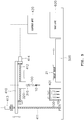
FIG. 1 is a sectional view showing a pipette tip according to the present invention. -
FIGS. 2a to 2f are views showing various embodiments of flat cross-section of a capillary tube of the pipette tip according to the present invention. -
FIG. 3 is an enlarged sectional view showing a sample collection part of a pipette tip according to another embodiment of the present invention. -
FIGS. 4a to 4f are views showing a method of using the pipette tip according to the present invention. -
FIG. 5 is a view showing a configuration of a pipette system according to the present invention. - In the following description, the structural or functional description specified to exemplary embodiments according to the concept of the present invention is intended to describe the exemplary embodiments, so it should be understood that the present invention may be variously embodied, without being limited to the exemplary embodiments. It should be understood that the exemplary embodiments according to the concept of the present invention are not limited to the embodiments which will be described hereinbelow with reference to the accompanying drawings, but various modifications, equivalents, additions and substitutions are possible, without departing from the scope and spirit of the invention.
- It will be understood that, although the terms first, second, etc. may be used herein to describe various elements, these elements should not be limited by these terms. These terms are only used to distinguish one element, from another element. For instance, a first element discussed below could be termed a second element without departing from the teachings of the present invention. Similarly, the second element could also be termed the first element.
- It will be understood that when an element is referred to as being "coupled" or "connected" to another element, it can be directly coupled or connected to the other element or intervening elements may be present therebetween. In contrast, it should be understood that when an element is referred to as being "directly coupled" or "directly connected" to another element, there are no intervening elements present. Further, the terms used herein to describe a relationship between elements, for example, "between", "directly between", "adjacent", or "directly adjacent" should be interpreted in the same manner as those described above.
- The terminology used herein is for the purpose of describing particular embodiments only and is not intended to be limiting. As used herein, the singular forms "a", "an", and "the" are intended to include the plural forms as well, unless the context clearly indicates otherwise. It will be further understood that the terms "comprise", "include", "have", etc. when used in this specification, specify the presence of stated features, integers, steps, operations, elements, components, and/or combinations of them but do not preclude the presence or addition of one or more other features, integers, steps, operations, elements, components, and/or combinations thereof.
- Hereinafter, the present invention will be described in detail with reference to the accompanying drawings.
- As shown in
FIG. 1 , apipette tip 100 according to the present invention includes: asample collection part 110 in which a capillary 111 is formed in a longitudinal direction for introducing samples; and abarrel body 120 having asample storage chamber 122 that communicates with thecapillary tube 111 through astepped portion 121 and in which the sample is stored. - The
sample collection part 110 and thebarrel body 120 are integrally formed with each other and may be made of glass or plastic, but are not limited to a specific material. However, it is preferable that a material having a high rigidity be used so as not to cause deformation due to an external force. - Furthermore, in order to enable an effective capillary action of the
sample collection part 110, a hydrophilic material may be used or a hydrophilic thin film may be coated on the inner circumferential surface of thecapillary tube 111. - The
capillary tube 111 is formed through thesample collection part 110 along the longitudinal direction of the sample collecting part and stores the sample by capillary action. Herein, a collection volume of about 5 µℓ to 100 µℓ may be possible. - The size (diameter) of the
capillary tube 111 may be determined within a range in which the sample can be collected by capillary action, preferably within about 0.5 mm to 1.5 mm. - The
barrel body 120 is integrally formed with thesample collection part 110 and has thesample storage chamber 122 communicating with the rear end of thecapillary tube 111. Thesample storage chamber 122 extends from the rear end of thecapillary tube 111 through the steppedportion 121 and is larger in diameter than thecapillary tube 111. - In
FIG. 1 , an inclination angle of the steppedportion 121 with respect to the capillary 111 is a right angle. However, it was confirmed that when the inclination angle θ is equal to or greater than 45°, a liquid sample collected by capillary action is only filled up to thecapillary tube 111. Furthermore, the inclination angle θ may be equal to or greater than 90°. - The
sample storage chamber 122 is formed through the center of thebarrel body 120 and provides a space in which the sample is mixed with a pretreatment solution. It is preferable that thesample storage chamber 122 have a conical inclined surface that is inclined upward from the steppedportion 121. - Herein, the
sample storage chamber 122 has a wide rear opening. The rear opening of the sample storage chamber may be assembled with an automated instrument having a tapered surface that corresponds to the opening by luer lock fitting. It is preferable that thesample storage chamber 122 have anannular engagement groove 123 that is formed in the inner surface thereof so as to be fitted to a protrusion protruding from the tapered surface of the automated instrument. - The
pipette tip 100 according to the present invention configured as described above is configured such that a correct collection volume thereof is determined by the volume of thecapillary tube 111 of thesample collection part 110. That is, the volume of the capillary 111 is determined by the cross-sectional area and a length L of thecapillary tube 111, and a collected sample fills thecapillary tube 111 below the steppedportion 121 by capillary action. - Meanwhile, in the present invention, the cross-sectional shape of the capillary tube may be variously modified in consideration of the collection volume of the pipette tip. For example, in order to increase the collection volume of the pipette tip, it is required to increase the length L of the sample collection part. However, in the present invention, the cross-sectional area of the capillary tube may be increased for a large collection volume.
-
FIGS. 2a to 2f are views showing various embodiments of flat cross-section of the capillary tube of the pipette tip according to the present invention. - Referring to
FIGS. 2a to 2f , acapillary tube 111a inFIG. 2a has a circular-shaped cross-section, and acapillary tube 111b inFIG. 2b has a long hole-shaped cross-section. Furthermore, acapillary tube 111c inFIG. 2c has a cross-shaped cross-section, and acapillary tube 111d inFIG. 2d has a star-shaped cross-section formed by multiple bar-shaped holes intersecting with each other at positions circumferentially spaced out at regular angular intervals. - Meanwhile, it is preferable that a size d (diameter or width) of each of the
capillary tubes - As another embodiment,
FIG. 2e shows that acapillary tube 111e has an annular-shaped cross-section that is defined between a core 112 placed in a circular hole and the wall of the circular hole. Herein, a diameter d1 of thecapillary tube 111e itself is larger than that of the capillary tubes of the embodiments inFIGS. 2a, 2b, 2c, and 2d . At the same time, an effective size d due to the size of thecore 112 is determined within a range of 0.5 mm to 1.5 mm in which capillary action can be affected. This results in an increase in effective cross-sectional area, thus ensuring that collection of a large-volume sample can be achieved. As still another embodiment,FIG. 2f shows that acapillary tube 111e has a rectangular ring-shaped cross-section that is defined between a core 113 placed in a rectangular hole and the wall of the rectangular hole. -
FIG. 3 is an enlarged sectional view showing a sample collection part of a pipette tip according to another embodiment of the present invention. - Referring to
FIG. 3 ,capillary tubes sample collection part 210 of the pipette tip according to the present invention are comprised of a firstcapillary tube 211 formed in a front opening, and a secondcapillary tube 212 having a smaller cross-sectional area than the firstcapillary tube 211 and communicating therewith. - Meanwhile, it is preferable that the size (diameter or width) of the second
capillary tube 212 be determined to be equal to or less than 1.5 mm such that capillary action can be affected. It is more preferable that the firstcapillary tube 211 and the secondcapillary tube 212 communicates with each other through a steppedportion 211a. - The capillary tube configured as described above is comprised of a first capillary tube section A and a second capillary tube section B, and the respective sections communicate with each other through the stepped portion. This ensures that it is possible to facilitate the design of a large-volume pipette tip or design of a pipette tip having various collection volumes, and the manufacture thereof.
- In detail with reference to
FIG. 1 , in the case where the entire section of thecapillary tube 111 has the same diameter, a pipette tip for collecting a large-volume liquid sample requires that the length of thecapillary tube 111 be longer in proportion to the design volume. This may cause a problem in that, when the pipette tip is applied to an automated analyzer, occurrence of interference due to the length of the pipette tip has to be considered. - Therefore, in the present invention, as shown in
FIG. 3 , thepipette tip 200 for collecting a large-volume liquid sample (50 µℓ <) is designed such that the pipette tip is divided into at least two sections depending on the collection volume, and one of the sections formed in the front opening has a predetermined length L2 with a large diameter. This ensures that the design of a required collection volume can be achieved while limiting a total length L1 of thecapillary tubes -
FIGS. 4a to 4f are views showing a method of using the pipette tip according to the present invention. - As shown in
FIG. 4a , thesample 10 is collected with thepipette tip 100. At this time, a fixed volume of thesample 10 is accurately collected in the capillary tube of thesample collection part 110 by capillary action. - Thereafter, as shown in
FIG. 4b , thepipette tip 100 having thesample 10 collected therein is mounted on a handler for controlling pressure. - The handler includes an
adapter 310 having a flow path formed therethrough and assembled with thepipette tip 100, and a pump configured to generate a positive pressure or negative pressure acting on thepipette tip 100 through theadapter 310. Theadapter 310 is a hollow tube and is fitted to an upper portion of thepipette tip 100, and is connected to thepump 320 through a pipe. - Thereafter, as shown in
FIG. 4c , the sample in thesample collection part 110 of thepipette tip 100 is introduced into thebarrel body 120 by the negative pressure generated by the handler and stored therein. - Thereafter, as shown in
FIGS. 4d and 4e , thepipette tip 100 mounted on the handler is transferred into apretreatment solution 20, and thesample 10 and thepretreatment solution 20 are mixed to obtain amixed liquid 30. At this time, discharge of thesample 10 in thepipette tip 100 upon transfer is made by the positive pressure generated by thepump 320. - Thereafter, as shown in
FIG. 4f , themixed liquid 30 is sucked up into thepipette tip 100, and the sucked mixed liquid 30 can be dispensed at a desired position. At this time, themixed liquid 30 is sucked up into thepipette tip 100 by the negative pressure generated by thepump 320. -
FIG. 5 is a view showing a configuration of a pipette system according to the present invention. - As shown in
FIG. 5 , a pipette system according to the present invention includes: a guide part for guiding movement of theadapter 310; a driving part for generating a driving force for controlling the movement of theadapter 310 along the guide part; and a control unit for controlling operations of a pump and the driving part. - In this embodiment, the
adapter 310 is a module type integrally formed with thepump 320. Theadapter 310 is provided at a lower surface of thepump 320 such that the pump is moved together with theadapter 310. On the other hand, the adapter may be connected to the pump by a flexible hose such that only the adapter can be moved for operation. - The guide part guides movement of the
adapter 310 between a pipette tip site wheremultiple pipette tips 100 each having a fixed volume of a liquid sample collected therein are located, and a reagent cartridge site where areagent cartridge 21 is located. In this embodiment, the guide part is comprised of avertical ball screw 411, amovable frame 410 guided by thevertical ball screw 411 so as to be moved vertically, and ahorizontal ball screw 412 provided horizontally at themovable frame 410 to guide a horizontal movement of thepump 320. - In this embodiment, the
pipette tips 100 are stored in arack 401 provided at a designated position in a state of having the fixed volumes of the liquid samples collected therein, and thereagent cartridge 21 is provided at a side of atransfer device 500. - The
vertical ball screw 411 and thehorizontal ball screw 412 are provided to be rotatable by well-known bearings. The vertical and horizontal ball screws include afirst driving motor 413 and asecond driving motor 414 for rotating the ball screws, respectively. - The
control unit 420 controls operations of thepump 320 and the first andsecond driving motors control unit 420 controls thefirst driving motor 413 and thesecond driving motor 413 to control the movement position of theadapter 310. Also, the control unit moves apipette tip 100 having a liquid sample collected therein to thereagent cartridge 21 to allow the liquid sample to be mixed with a pretreatment solution of thereagent cartridge 21 or dispensed. - Meanwhile, the
control unit 420 controls thepump 320 such that an appropriate pressure acts on thepipette tip 100 in the process of moving thepipette tip 100 and mixing or dispensing the liquid sample therein, thus preventing leakage of the liquid sample that may occur in the process of moving the pipette tip, and facilitating mixing of the liquid sample with the pretreatment solution or dispensing thereof. - The
reagent cartridge 21 in which the liquid sample is mixed with the pretreatment solution or dispensed is transferred to atest unit 600 by thetransfer device 500 and subjected to a test. - In this embodiment, the guide part has been described as performing a biaxial movement in vertical and horizontal directions. However, it should be understood that movement in three axial directions can be performed by additional provision of a guide member and a driving source that are located in directions perpendicular to the vertical and horizontal directions.
- Although the exemplary embodiments of the present invention have been disclosed for illustrative purposes, those skilled in the art will appreciate that various modifications, additions and substitutions are possible, without departing from the scope and spirit of the invention as disclosed in the accompanying claims.
<Description of the Reference Numerals in the Drawings> 100: pipette tip 110: sample collection part 111: capillary tube 120: barrel body 121: stepped portion 122: sample storage chamber 310: adapter 320: pump 410: movable frame 411: vertical ball screw 412: horizontal ball screw 420: control unit 500: transfer device 600: test unit
Claims (7)
- A pipette tip, comprising:a sample collection part having a capillary tube formed in a longitudinal direction for introducing samples; anda barrel body having a sample storage chamber which communicates with the capillary tube through a stepped portion and stores the samples.
- The pipette tip of claim 1, wherein the stepped portion has an inclination angle with the capillary tube of equal to or greater than 45°.
- The pipette tip of claim 1, wherein the capillary tube includes:a first capillary tube; anda second capillary tube having a different cross-sectional area from that of the first capillary tube.
- The pipette tip of claim 1, wherein the capillary tube has a cross section of an elongated circle or of a cross.
- A pipette system, comprising:a pipette tip including a sample collection part having a capillary tube formed in a longitudinal direction for introducing samples, and a barrel body having a sample storage chamber which communicates with the capillary tube through a stepped portion and stores the samples; anda handler configured to control pressure inside the pipette tip by a pressure source that is secured to an end of the barrel body and is driven by an electrical control signal.
- The pipette system of claim 5, wherein the handler includes:an adapter having a flow path formed therethrough, and fitted to an opening of the barrel body; anda pump controlling the pressure inside the pipette tip through the adapter by the electrical control signal input from outside.
- The pipette system of claim 6, wherein the handler includes:a guide part guiding movement of the adapter between a site where the pipette tip is located and a site where a reagent cartridge is located;a driving part generating a driving force for controlling the movement of the adapter along the guide part; anda control unit generating an electrical control signal for controlling operation of the pump and the driving part.
Applications Claiming Priority (1)
| Application Number | Priority Date | Filing Date | Title |
|---|---|---|---|
| PCT/KR2016/012256 WO2018079884A1 (en) | 2016-10-28 | 2016-10-28 | Pipette tip and pipette system |
Publications (3)
| Publication Number | Publication Date |
|---|---|
| EP3533521A1 true EP3533521A1 (en) | 2019-09-04 |
| EP3533521A4 EP3533521A4 (en) | 2020-05-27 |
| EP3533521B1 EP3533521B1 (en) | 2021-06-09 |
Family
ID=62023700
Family Applications (1)
| Application Number | Title | Priority Date | Filing Date |
|---|---|---|---|
| EP16919641.7A Active EP3533521B1 (en) | 2016-10-28 | 2016-10-28 | Pipette tip and pipette system |
Country Status (3)
| Country | Link |
|---|---|
| EP (1) | EP3533521B1 (en) |
| ES (1) | ES2878311T3 (en) |
| WO (1) | WO2018079884A1 (en) |
Families Citing this family (2)
| Publication number | Priority date | Publication date | Assignee | Title |
|---|---|---|---|---|
| KR102573226B1 (en) * | 2020-07-29 | 2023-09-01 | 주식회사 아이센스 | Pipette tip and pipette system for collecting capillary |
| CN115106143A (en) * | 2022-06-29 | 2022-09-27 | 合肥瀚海星点生物科技有限公司 | High-precision electric micro-liquid pipettor |
Family Cites Families (10)
| Publication number | Priority date | Publication date | Assignee | Title |
|---|---|---|---|---|
| US4707337A (en) * | 1986-08-11 | 1987-11-17 | Multi-Technology, Inc. | Medical micro pipette tips for difficult to reach places and related methods |
| US20070081159A1 (en) * | 2005-10-11 | 2007-04-12 | Giffin Kristin M | Apparatus and methods for evaluating an optical property of a liquid sample |
| JP2007209478A (en) * | 2006-02-08 | 2007-08-23 | Morinaga & Co Ltd | Blood-collecting vessel for small animal, and blood collecting apparatus for small animal using the same |
| CN101437616B (en) * | 2006-05-03 | 2012-05-23 | Ncl新概念实验室有限责任公司 | Device and method for chemical, biochemical, biological and physical analysis, reaction, assay and more |
| JP2007315793A (en) * | 2006-05-23 | 2007-12-06 | Neat:Kk | Pipette tip used for measuring sampled liquid, measuring method using pipette tip and measuring instrument |
| WO2008062869A1 (en) * | 2006-11-22 | 2008-05-29 | Altair Corporation | Pipette core member, pipette, and pipette device |
| FI20095230A0 (en) * | 2009-03-09 | 2009-03-09 | Thermo Fisher Scientific Oy | dilution Lace |
| CN103543282A (en) * | 2010-07-23 | 2014-01-29 | 贝克曼考尔特公司 | System for processing samples |
| KR101510823B1 (en) | 2014-04-15 | 2015-04-13 | 포항공과대학교 산학협력단 | Pipette tip |
| KR101713172B1 (en) * | 2015-08-04 | 2017-03-08 | 바디텍메드(주) | Pipette tip, and pipette system |
-
2016
- 2016-10-28 ES ES16919641T patent/ES2878311T3/en active Active
- 2016-10-28 EP EP16919641.7A patent/EP3533521B1/en active Active
- 2016-10-28 WO PCT/KR2016/012256 patent/WO2018079884A1/en unknown
Also Published As
| Publication number | Publication date |
|---|---|
| ES2878311T3 (en) | 2021-11-18 |
| EP3533521A4 (en) | 2020-05-27 |
| WO2018079884A1 (en) | 2018-05-03 |
| EP3533521B1 (en) | 2021-06-09 |
Similar Documents
| Publication | Publication Date | Title |
|---|---|---|
| US8114351B2 (en) | Analysis system and method for the analysis of a body fluid sample for an analyte contained therein | |
| DE19535046C2 (en) | Handheld device for pipetting and photometric measurement of samples | |
| EP1074302B1 (en) | Multichannel pipette system and pipette tips therefor | |
| EP2662671A1 (en) | Cartridge for dispensing a fluid | |
| US10386277B2 (en) | Container for specimen preparation | |
| US20120101407A1 (en) | Apparatus and method for preparation of small volume of samples | |
| JPH01257268A (en) | Apparatus and method for diluting and mixing liquid sample | |
| EP2050498A1 (en) | Fluid handling device for analysis of fluid samples | |
| CN101600963A (en) | The sampling of percutaneous biological fluid and pretreated apparatus and method | |
| US7318359B2 (en) | Sampling means and system for testing a sample liquid | |
| KR101713172B1 (en) | Pipette tip, and pipette system | |
| US20030012694A1 (en) | System for the analysis of biological liquids | |
| JP2006349638A (en) | Method and apparatus for homogenizing trace quantity of liquid | |
| EP3533521B1 (en) | Pipette tip and pipette system | |
| JP4819324B2 (en) | Analyzer with concentric rotor | |
| US3337095A (en) | Syringe for automatic proportioning | |
| US5183765A (en) | Means and method of measuring and dispensing | |
| JP2004301844A (en) | Test element holder with probe guide for analyzer | |
| US10768192B2 (en) | Device and method to sample liquids with high-precision in an automated sample analyzer | |
| US20070056360A1 (en) | Method and apparatus for sampling a fluid | |
| CN207913815U (en) | Pipettor gun head | |
| US20050197538A1 (en) | Reagent and sample introduction plunger device for a syringe | |
| JP2008157783A (en) | Sampling pipe for trace amount of sample | |
| WO2018110052A1 (en) | Dispensing device and dispensing method | |
| AT505469B1 (en) | SAMPLE INPUT DEVICE |
Legal Events
| Date | Code | Title | Description |
|---|---|---|---|
| STAA | Information on the status of an ep patent application or granted ep patent |
Free format text: STATUS: THE INTERNATIONAL PUBLICATION HAS BEEN MADE |
|
| PUAI | Public reference made under article 153(3) epc to a published international application that has entered the european phase |
Free format text: ORIGINAL CODE: 0009012 |
|
| STAA | Information on the status of an ep patent application or granted ep patent |
Free format text: STATUS: REQUEST FOR EXAMINATION WAS MADE |
|
| 17P | Request for examination filed |
Effective date: 20190527 |
|
| AK | Designated contracting states |
Kind code of ref document: A1 Designated state(s): AL AT BE BG CH CY CZ DE DK EE ES FI FR GB GR HR HU IE IS IT LI LT LU LV MC MK MT NL NO PL PT RO RS SE SI SK SM TR |
|
| AX | Request for extension of the european patent |
Extension state: BA ME |
|
| DAV | Request for validation of the european patent (deleted) | ||
| DAX | Request for extension of the european patent (deleted) | ||
| A4 | Supplementary search report drawn up and despatched |
Effective date: 20200424 |
|
| RIC1 | Information provided on ipc code assigned before grant |
Ipc: B01L 3/02 20060101AFI20200420BHEP Ipc: G01N 35/10 20060101ALI20200420BHEP |
|
| GRAP | Despatch of communication of intention to grant a patent |
Free format text: ORIGINAL CODE: EPIDOSNIGR1 |
|
| STAA | Information on the status of an ep patent application or granted ep patent |
Free format text: STATUS: GRANT OF PATENT IS INTENDED |
|
| INTG | Intention to grant announced |
Effective date: 20210302 |
|
| GRAS | Grant fee paid |
Free format text: ORIGINAL CODE: EPIDOSNIGR3 |
|
| GRAA | (expected) grant |
Free format text: ORIGINAL CODE: 0009210 |
|
| STAA | Information on the status of an ep patent application or granted ep patent |
Free format text: STATUS: THE PATENT HAS BEEN GRANTED |
|
| AK | Designated contracting states |
Kind code of ref document: B1 Designated state(s): AL AT BE BG CH CY CZ DE DK EE ES FI FR GB GR HR HU IE IS IT LI LT LU LV MC MK MT NL NO PL PT RO RS SE SI SK SM TR |
|
| REG | Reference to a national code |
Ref country code: GB Ref legal event code: FG4D |
|
| REG | Reference to a national code |
Ref country code: CH Ref legal event code: EP Ref country code: AT Ref legal event code: REF Ref document number: 1400020 Country of ref document: AT Kind code of ref document: T Effective date: 20210615 |
|
| REG | Reference to a national code |
Ref country code: DE Ref legal event code: R096 Ref document number: 602016059264 Country of ref document: DE |
|
| REG | Reference to a national code |
Ref country code: IE Ref legal event code: FG4D |
|
| REG | Reference to a national code |
Ref country code: LT Ref legal event code: MG9D |
|
| PG25 | Lapsed in a contracting state [announced via postgrant information from national office to epo] |
Ref country code: HR Free format text: LAPSE BECAUSE OF FAILURE TO SUBMIT A TRANSLATION OF THE DESCRIPTION OR TO PAY THE FEE WITHIN THE PRESCRIBED TIME-LIMIT Effective date: 20210609 Ref country code: BG Free format text: LAPSE BECAUSE OF FAILURE TO SUBMIT A TRANSLATION OF THE DESCRIPTION OR TO PAY THE FEE WITHIN THE PRESCRIBED TIME-LIMIT Effective date: 20210909 Ref country code: FI Free format text: LAPSE BECAUSE OF FAILURE TO SUBMIT A TRANSLATION OF THE DESCRIPTION OR TO PAY THE FEE WITHIN THE PRESCRIBED TIME-LIMIT Effective date: 20210609 Ref country code: LT Free format text: LAPSE BECAUSE OF FAILURE TO SUBMIT A TRANSLATION OF THE DESCRIPTION OR TO PAY THE FEE WITHIN THE PRESCRIBED TIME-LIMIT Effective date: 20210609 |
|
| REG | Reference to a national code |
Ref country code: AT Ref legal event code: MK05 Ref document number: 1400020 Country of ref document: AT Kind code of ref document: T Effective date: 20210609 |
|
| REG | Reference to a national code |
Ref country code: NL Ref legal event code: MP Effective date: 20210609 |
|
| REG | Reference to a national code |
Ref country code: ES Ref legal event code: FG2A Ref document number: 2878311 Country of ref document: ES Kind code of ref document: T3 Effective date: 20211118 |
|
| PG25 | Lapsed in a contracting state [announced via postgrant information from national office to epo] |
Ref country code: GR Free format text: LAPSE BECAUSE OF FAILURE TO SUBMIT A TRANSLATION OF THE DESCRIPTION OR TO PAY THE FEE WITHIN THE PRESCRIBED TIME-LIMIT Effective date: 20210910 Ref country code: LV Free format text: LAPSE BECAUSE OF FAILURE TO SUBMIT A TRANSLATION OF THE DESCRIPTION OR TO PAY THE FEE WITHIN THE PRESCRIBED TIME-LIMIT Effective date: 20210609 Ref country code: NO Free format text: LAPSE BECAUSE OF FAILURE TO SUBMIT A TRANSLATION OF THE DESCRIPTION OR TO PAY THE FEE WITHIN THE PRESCRIBED TIME-LIMIT Effective date: 20210909 Ref country code: RS Free format text: LAPSE BECAUSE OF FAILURE TO SUBMIT A TRANSLATION OF THE DESCRIPTION OR TO PAY THE FEE WITHIN THE PRESCRIBED TIME-LIMIT Effective date: 20210609 Ref country code: SE Free format text: LAPSE BECAUSE OF FAILURE TO SUBMIT A TRANSLATION OF THE DESCRIPTION OR TO PAY THE FEE WITHIN THE PRESCRIBED TIME-LIMIT Effective date: 20210609 |
|
| PG25 | Lapsed in a contracting state [announced via postgrant information from national office to epo] |
Ref country code: CZ Free format text: LAPSE BECAUSE OF FAILURE TO SUBMIT A TRANSLATION OF THE DESCRIPTION OR TO PAY THE FEE WITHIN THE PRESCRIBED TIME-LIMIT Effective date: 20210609 Ref country code: EE Free format text: LAPSE BECAUSE OF FAILURE TO SUBMIT A TRANSLATION OF THE DESCRIPTION OR TO PAY THE FEE WITHIN THE PRESCRIBED TIME-LIMIT Effective date: 20210609 Ref country code: AT Free format text: LAPSE BECAUSE OF FAILURE TO SUBMIT A TRANSLATION OF THE DESCRIPTION OR TO PAY THE FEE WITHIN THE PRESCRIBED TIME-LIMIT Effective date: 20210609 Ref country code: NL Free format text: LAPSE BECAUSE OF FAILURE TO SUBMIT A TRANSLATION OF THE DESCRIPTION OR TO PAY THE FEE WITHIN THE PRESCRIBED TIME-LIMIT Effective date: 20210609 Ref country code: PT Free format text: LAPSE BECAUSE OF FAILURE TO SUBMIT A TRANSLATION OF THE DESCRIPTION OR TO PAY THE FEE WITHIN THE PRESCRIBED TIME-LIMIT Effective date: 20211011 Ref country code: RO Free format text: LAPSE BECAUSE OF FAILURE TO SUBMIT A TRANSLATION OF THE DESCRIPTION OR TO PAY THE FEE WITHIN THE PRESCRIBED TIME-LIMIT Effective date: 20210609 Ref country code: SK Free format text: LAPSE BECAUSE OF FAILURE TO SUBMIT A TRANSLATION OF THE DESCRIPTION OR TO PAY THE FEE WITHIN THE PRESCRIBED TIME-LIMIT Effective date: 20210609 Ref country code: SM Free format text: LAPSE BECAUSE OF FAILURE TO SUBMIT A TRANSLATION OF THE DESCRIPTION OR TO PAY THE FEE WITHIN THE PRESCRIBED TIME-LIMIT Effective date: 20210609 |
|
| PG25 | Lapsed in a contracting state [announced via postgrant information from national office to epo] |
Ref country code: PL Free format text: LAPSE BECAUSE OF FAILURE TO SUBMIT A TRANSLATION OF THE DESCRIPTION OR TO PAY THE FEE WITHIN THE PRESCRIBED TIME-LIMIT Effective date: 20210609 |
|
| REG | Reference to a national code |
Ref country code: DE Ref legal event code: R097 Ref document number: 602016059264 Country of ref document: DE |
|
| PLBE | No opposition filed within time limit |
Free format text: ORIGINAL CODE: 0009261 |
|
| STAA | Information on the status of an ep patent application or granted ep patent |
Free format text: STATUS: NO OPPOSITION FILED WITHIN TIME LIMIT |
|
| PG25 | Lapsed in a contracting state [announced via postgrant information from national office to epo] |
Ref country code: DK Free format text: LAPSE BECAUSE OF FAILURE TO SUBMIT A TRANSLATION OF THE DESCRIPTION OR TO PAY THE FEE WITHIN THE PRESCRIBED TIME-LIMIT Effective date: 20210609 |
|
| 26N | No opposition filed |
Effective date: 20220310 |
|
| PG25 | Lapsed in a contracting state [announced via postgrant information from national office to epo] |
Ref country code: AL Free format text: LAPSE BECAUSE OF FAILURE TO SUBMIT A TRANSLATION OF THE DESCRIPTION OR TO PAY THE FEE WITHIN THE PRESCRIBED TIME-LIMIT Effective date: 20210609 |
|
| REG | Reference to a national code |
Ref country code: BE Ref legal event code: MM Effective date: 20211031 |
|
| PG25 | Lapsed in a contracting state [announced via postgrant information from national office to epo] |
Ref country code: MC Free format text: LAPSE BECAUSE OF FAILURE TO SUBMIT A TRANSLATION OF THE DESCRIPTION OR TO PAY THE FEE WITHIN THE PRESCRIBED TIME-LIMIT Effective date: 20210609 |
|
| PG25 | Lapsed in a contracting state [announced via postgrant information from national office to epo] |
Ref country code: LU Free format text: LAPSE BECAUSE OF NON-PAYMENT OF DUE FEES Effective date: 20211028 Ref country code: BE Free format text: LAPSE BECAUSE OF NON-PAYMENT OF DUE FEES Effective date: 20211031 |
|
| PG25 | Lapsed in a contracting state [announced via postgrant information from national office to epo] |
Ref country code: IE Free format text: LAPSE BECAUSE OF NON-PAYMENT OF DUE FEES Effective date: 20211028 |
|
| PG25 | Lapsed in a contracting state [announced via postgrant information from national office to epo] |
Ref country code: CY Free format text: LAPSE BECAUSE OF FAILURE TO SUBMIT A TRANSLATION OF THE DESCRIPTION OR TO PAY THE FEE WITHIN THE PRESCRIBED TIME-LIMIT Effective date: 20210609 |
|
| PG25 | Lapsed in a contracting state [announced via postgrant information from national office to epo] |
Ref country code: HU Free format text: LAPSE BECAUSE OF FAILURE TO SUBMIT A TRANSLATION OF THE DESCRIPTION OR TO PAY THE FEE WITHIN THE PRESCRIBED TIME-LIMIT; INVALID AB INITIO Effective date: 20161028 |
|
| PGFP | Annual fee paid to national office [announced via postgrant information from national office to epo] |
Ref country code: GB Payment date: 20231027 Year of fee payment: 8 |
|
| PGFP | Annual fee paid to national office [announced via postgrant information from national office to epo] |
Ref country code: ES Payment date: 20231102 Year of fee payment: 8 |
|
| PGFP | Annual fee paid to national office [announced via postgrant information from national office to epo] |
Ref country code: IT Payment date: 20231023 Year of fee payment: 8 Ref country code: FR Payment date: 20231025 Year of fee payment: 8 Ref country code: DE Payment date: 20231027 Year of fee payment: 8 Ref country code: CH Payment date: 20231102 Year of fee payment: 8 |
|
| PG25 | Lapsed in a contracting state [announced via postgrant information from national office to epo] |
Ref country code: MK Free format text: LAPSE BECAUSE OF FAILURE TO SUBMIT A TRANSLATION OF THE DESCRIPTION OR TO PAY THE FEE WITHIN THE PRESCRIBED TIME-LIMIT Effective date: 20210609 |