EP3533374A1 - Improved dishwashing arrangement and method - Google Patents
Improved dishwashing arrangement and method Download PDFInfo
- Publication number
- EP3533374A1 EP3533374A1 EP18159834.3A EP18159834A EP3533374A1 EP 3533374 A1 EP3533374 A1 EP 3533374A1 EP 18159834 A EP18159834 A EP 18159834A EP 3533374 A1 EP3533374 A1 EP 3533374A1
- Authority
- EP
- European Patent Office
- Prior art keywords
- items
- zone
- zones
- washing
- washing chamber
- Prior art date
- Legal status (The legal status is an assumption and is not a legal conclusion. Google has not performed a legal analysis and makes no representation as to the accuracy of the status listed.)
- Withdrawn
Links
Images


Classifications
-
- A—HUMAN NECESSITIES
- A47—FURNITURE; DOMESTIC ARTICLES OR APPLIANCES; COFFEE MILLS; SPICE MILLS; SUCTION CLEANERS IN GENERAL
- A47L—DOMESTIC WASHING OR CLEANING; SUCTION CLEANERS IN GENERAL
- A47L15/00—Washing or rinsing machines for crockery or tableware
- A47L15/0018—Controlling processes, i.e. processes to control the operation of the machine characterised by the purpose or target of the control
- A47L15/0021—Regulation of operational steps within the washing processes, e.g. optimisation or improvement of operational steps depending from the detergent nature or from the condition of the crockery
- A47L15/0028—Washing phases
-
- A—HUMAN NECESSITIES
- A47—FURNITURE; DOMESTIC ARTICLES OR APPLIANCES; COFFEE MILLS; SPICE MILLS; SUCTION CLEANERS IN GENERAL
- A47L—DOMESTIC WASHING OR CLEANING; SUCTION CLEANERS IN GENERAL
- A47L15/00—Washing or rinsing machines for crockery or tableware
- A47L15/0018—Controlling processes, i.e. processes to control the operation of the machine characterised by the purpose or target of the control
- A47L15/0021—Regulation of operational steps within the washing processes, e.g. optimisation or improvement of operational steps depending from the detergent nature or from the condition of the crockery
- A47L15/0026—Rinsing phases
-
- A—HUMAN NECESSITIES
- A47—FURNITURE; DOMESTIC ARTICLES OR APPLIANCES; COFFEE MILLS; SPICE MILLS; SUCTION CLEANERS IN GENERAL
- A47L—DOMESTIC WASHING OR CLEANING; SUCTION CLEANERS IN GENERAL
- A47L15/00—Washing or rinsing machines for crockery or tableware
- A47L15/14—Washing or rinsing machines for crockery or tableware with stationary crockery baskets and spraying devices within the cleaning chamber
- A47L15/18—Washing or rinsing machines for crockery or tableware with stationary crockery baskets and spraying devices within the cleaning chamber with movably-mounted spraying devices
-
- A—HUMAN NECESSITIES
- A47—FURNITURE; DOMESTIC ARTICLES OR APPLIANCES; COFFEE MILLS; SPICE MILLS; SUCTION CLEANERS IN GENERAL
- A47L—DOMESTIC WASHING OR CLEANING; SUCTION CLEANERS IN GENERAL
- A47L15/00—Washing or rinsing machines for crockery or tableware
- A47L15/42—Details
- A47L15/4295—Arrangements for detecting or measuring the condition of the crockery or tableware, e.g. nature or quantity
-
- A—HUMAN NECESSITIES
- A47—FURNITURE; DOMESTIC ARTICLES OR APPLIANCES; COFFEE MILLS; SPICE MILLS; SUCTION CLEANERS IN GENERAL
- A47L—DOMESTIC WASHING OR CLEANING; SUCTION CLEANERS IN GENERAL
- A47L15/00—Washing or rinsing machines for crockery or tableware
- A47L15/42—Details
- A47L15/4297—Arrangements for detecting or measuring the condition of the washing water, e.g. turbidity
-
- A—HUMAN NECESSITIES
- A47—FURNITURE; DOMESTIC ARTICLES OR APPLIANCES; COFFEE MILLS; SPICE MILLS; SUCTION CLEANERS IN GENERAL
- A47L—DOMESTIC WASHING OR CLEANING; SUCTION CLEANERS IN GENERAL
- A47L2401/00—Automatic detection in controlling methods of washing or rinsing machines for crockery or tableware, e.g. information provided by sensors entered into controlling devices
- A47L2401/10—Water cloudiness or dirtiness, e.g. turbidity, foaming or level of bacteria
-
- A—HUMAN NECESSITIES
- A47—FURNITURE; DOMESTIC ARTICLES OR APPLIANCES; COFFEE MILLS; SPICE MILLS; SUCTION CLEANERS IN GENERAL
- A47L—DOMESTIC WASHING OR CLEANING; SUCTION CLEANERS IN GENERAL
- A47L2501/00—Output in controlling method of washing or rinsing machines for crockery or tableware, i.e. quantities or components controlled, or actions performed by the controlling device executing the controlling method
- A47L2501/30—Regulation of machine operational steps within the washing process, e.g. performing an additional rinsing phase, shortening or stopping of the drying phase, washing at decreased noise operation conditions
Definitions
- the present invention relates to an improved dishwashing arrangement and method.
- Dishwashing machines are well known in the art.
- automatic dishwashers comprise a sealable washing chamber having one or more baskets arranged to hold dishes, tableware and/or utensils.
- Automatic dishwashers operate by spraying high-pressure water onto the utensils to remove dirt and debris from the kitchenware items.
- a typical automatic dishwasher it is common for a typical automatic dishwasher to have a number of different cycles within a typical dishwashing programme. For example, there may be a preliminary washing cycle, followed by a main washing cycle, a rinse cycle and, optionally, a drying cycle.
- tableware and/or utensils loaded into a dishwasher may be soiled to different degrees. Therefore, some tableware and/or utensils may not need extensive cleaning, whereas others may not be sufficiently cleaned.
- the present invention in embodiments, addresses this issue.
- an automatic dishwasher comprising a washing chamber defining an interior space arranged to receive one or more items to be washed, a controller operable to define a plurality of discrete selectable zones within the washing chamber, one or more spray devices arranged within the washing chamber and operable to selectively spray washing liquid onto items to be washed in one or more of the selectable zones, and a turbidity sensor operable to measure the turbidity of waste water from the washing chamber, wherein the controller is operable, in use, to determine the level of soiling of items within one or more selected zones based on the measured turbidity during a washing operation in the one or more selected zones.
- the washing chamber further comprises a drain outlet arranged, in use, to receive waste water and wherein the turbidity sensor is located adjacent or downstream of the drain outlet.
- the turbidity sensor comprises a camera system.
- the controller is operable to select a wash program based on the determined level of soiling of items within the one or more selected zones.
- the controller is operable to identify the zone having the most heavily soiled items and select a wash program for the dishwasher based on the identified zone.
- At least 3 zones are provided. In one embodiment, at least 5 zones are provided.
- the or each spray device comprises a movable spray arm which is translatable in along at least one axis to enable washing liquid to be sprayed within a selected zone.
- the or each spray arm comprises an elongate member held in substantially fixed orientation with respect to the washing chamber.
- the or each spray arm is arranged to traverse each selected zone during in a washing operation in either a linear or an oscillatory manner.
- the controller is operable, in use, to determine the level of soiling of items within one or more selected zones based on the measured turbidity during a washing operation having a duration of less than two minutes.
- a method for selecting a wash program for an automatic dishwasher comprising the steps of: defining a plurality of discrete selectable zones within a washing chamber defining an interior space arranged to receive one or more items to be washed; spraying, using one or more spray devices arranged within the washing chamber, washing liquid onto items to be washed in a first selected zone; measuring, using a turbidity sensor, the turbidity of waste water from the washing chamber to determine the level of soiling of items within the first selected zone; repeating steps b) and c) for further selected zones; and selecting a wash program for the dishwasher based on the determined level of soiling of items within one or more selected zones.
- step e) comprises:identifying, based on the measured turbidity values for each zone, the zone having the most heavily soiled items and selecting a wash program for the dishwasher based on the identified zone.
- the method further comprises: performing the selected wash program.
- the method further comprises: after the selected was program has completed at step g), repeating steps b) and c) as a final verification step.
- a non-transitory computer readable storage medium comprising instructions stored thereon for executing the method of the second aspect.
- Figure 1 shows an exemplary automatic dishwasher 10 suitable for use with the present invention.
- the automatic dishwasher 10 comprises a main body 12 and a door 14.
- the door 14 is pivotably connected to the main body 12 such that the door 14 can be opened to provide access to a washing chamber 50.
- the washing chamber 50 comprises a substantially rectilinear chamber, one side of which is formed by the interior of the door 14. When the door 14 is closed, the washing chamber 50 forms a substantially sealed chamber into which washing liquid can be admitted.
- a pair of racks 52, 54 is provided within the washing chamber 50.
- the racks 52, 54 have rollers and are operable to slide on rails to enable the racks 52, 54 to be drawn out of the interior of the washing chamber 50 for emptying.
- the racks 52, 54 are operable to receive one or more items to be washed.
- the items to be washed may include, but are not limited to, items commonly used in a kitchen and in connection with the preparation and consumption of food, for example: dishes and other crockery; tableware; utensils; pots, pans and other cooking equipment; food preparation and chopping boards.
- Figure 2 shows a side section view of an automatic dishwasher 10 according to a first embodiment of the present invention.
- the dishwasher 10 has a washing chamber 50 having side walls 58 and a base 60.
- the base 60 has a drain outlet 62 at a lower end thereof.
- the drain outlet 62 may be connected to a pump (not shown) and other plumbing downstream of the drain outlet 62.
- a turbidity sensor 64 is located adjacent the drain outlet 62.
- the turbidity sensor 64 may comprise a camera or other photometric sensor to determine the turbidity of waste water leaving the drain outlet 62.
- other sensors may be used - for example, conductivity sensors, density sensors or other devices.
- the turbidity sensor 64 need not be located in the drain outlet 62 as shown. Instead, the turbidity sensor 64 may be located in any suitable location in the fluid pathway downstream of the drain outlet 62, or upstream of the drain outlet 62 prior to washing fluid entering the drain outlet 62.
- a pair of spray arms 66, 68 is located within the washing chamber 50.
- Each spray arm 66, 68 comprises an elongate member arranged to extend substantially from the front of the washing chamber 50 to substantially the rear of the washing chamber 50.
- a plurality of through-holes is formed in each spray arm 66, 68 and arranged to spray water onto the items to be washed 56.
- each spray arm 66, 68 is horizontally movable across the width of the washing chamber 50 by means of a motor drive 70.
- the motor drive 70 is, in embodiments, controlled by a controller 80 ( Figure 2 ).
- the controller 80 is operable to control all operational elements of the dishwasher 10, for example: programs; spray arm movement; cycle operation; water temperature and heaters; drainage and pump operation; and turbidity determination.
- the controller 80 may comprise a processor (not shown) and memory elements to enable storage and logging of data.
- the spray arm 66 is arranged in the middle section of the washing chamber 50 and operable to spray water and/or washing liquid onto items 56 in the rack 52.
- the spray arm 68 is arranged at the upper end of the washing chamber 50 and is operable to spray water and/or washing liquid onto items 56 in the rack 54.
- Each spray arm 66, 68 is, therefore, held in a fixed orientation with respect to the washing chamber 50 and is moved back and forth across the width of the washing chamber 50 to clean the items to be cleaned.
- spray arms 66, 68 Whilst two spray arms 66, 68 are shown in this embodiment, this need not be so. A single spray arm may be provided, or multiple spray arms may be provided as required. The skilled person would be readily aware of variations that fall within the scope of the present invention and what configurations are desired.
- each spray arm need not extend from the front wall of the washing chamber 50 to the rear wall of the washing chamber 50, and may be shorter than this.
- each spray arm may need to translate in two dimensions across the width and depth of the washing chamber 50. This may be used in conjunction with a rotatable spray arm to define a movable washing region below the respective spray arm.
- the spray arms need not be movable and a plurality of spray arms may extend across the width of the washing chamber 50, where each of the plurality of spray arms can be independently activated to target a specific area of the washing chamber 50.
- the washing chamber 50 is divided into five zones Z1 - Z5.
- Each zone Z1-Z5 comprises an elongate region extending from the front to the rear of the washing chamber 50 and having a predetermined width w1 -w5 respectively.
- Each zone Z1-Z5 may extend from the base 60 to the upper end of the washing chamber 50.
- each zone Z1-Z5 may be defined with respect to each rack 52, 54 and so each zone Z1-Z5 comprises an upper zone (rack 54) and a lower zone (rack 52) which may be functionally independent in use.
- the size of the zones Z1-Z5 may be defined as appropriate by a user (for example, to correspond to particular utensil or tableware regions of the particular rack) or may be predefined.
- the zones Z1-Z5 are defined to each cover one fifth of the washing chamber 50.
- the zones Z1-Z5 divide the washing chamber 50 into equal sections.
- the zones may be based on the region in which items to be cleaned 56 are to be located in use.
- the zones may be selected relative to the dimensions of the rack(s) 52, 54 within the washing chamber 50.
- the rack(s) 52, 54 have a width of 50cm. Therefore, the width w1-w5 of each zone Z1-Z5 is 10cm.
- the use of the defined zones Z1-Z5 enables specific regions of the washing chamber 50 to be measured and targeted as appropriate. For example, a particular zone Z1-Z5 can be targeted individually to determine the level of soiling of the items to be washed 56 in that zone. If a particular zone, for example, zone Z1, contains items with heavy soiling, then additional washing time, intensity or detergent (for example) can be applied to items in that zone.
- the spray arm 66, 68 can be located at a particular zone Z1-Z5 and caused to spray washing liquid on items within that specific zone.
- the spray arm 66, 68 can be directed in a number of ways.
- the spray arm 66, 68 could move or oscillate back and forth within the selected zone whilst spraying washing liquid on the items to be cleaned 56. During this operation, the spray arm 66, 68 would spray water or washing liquid through the items to be washed 56 located within the exemplary 10 cm region of a particular zone. Alternatively, the spray arm 66, 68 may move slowly across the 10cm partial region during the cycle in that zone.
- the present invention enables detection and profiling of the soiling of items to be washed 56 across the washing chamber 50. This enables selection of an appropriate washing cycle to ensure that that items to be cleaned 56 are cleaned appropriately whilst minimising water usage.
- items having particularly heavy soiling e.g. ovenware, pots and pans
- other items for examples, dishes or cutlery
- the profiling of the different zones is achieved by performing test cycle washes in individual zones Z1-Z5 and measuring the turbidity of the water exiting from the drain outlet 62 using the turbidity sensor 64.
- the turbidity sensor 64 comprises a camera system operable to determine the turbidity (i.e. cloudiness/opacity) of the water leaving the drain outlet 62. The turbidity measured for each zone Z1-Z5 can then be compared and the zones containing items to be washed having the heaviest soiling can be identified. This information can be then used by the processor 80 to select an appropriate washing program or a custom selection to enable targeting of the most soiled items.
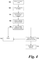
- Figure 4 shows a flow chart of a method of operation of an automatic dishwasher 10 according to an embodiment of the present invention.
- Step 100 Define n partial test zones
- Step 100 is optional and can be used to defined particular zones Z1-Z5 within the interior of the washing chamber 50.
- the zones Z1-Z5 may be defined by a user or may be automatically specified.
- the zones are defined in accordance with the zones Z1-Z5 discussed in relation to Figure 3 .
- five consecutive zones, of 10cm width each, are defined across the width of the interior of the washing chamber 50.
- step 102 the method proceeds to step 102.
- Step 102 Carry out test cycle in n zones
- step 102 a partial washing test cycle in carried out for each of the zones Z1-Z5 defined in step 100.
- Each partial test cycle for a given zone involves three processes:
- step 1) of step 102 the spray arm 66, 68 moves to the correct location for the zone in question (e.g. zone Z1) and spray washing liquid (which may be water, detergent or a combination thereof) onto the items 56 in zone Z1 for a predetermined period of time.
- the period of time may be of the order of 5 to 20 seconds. However, this is taken to be non-limiting and other time periods may be used. It is useful that the time period are substantially the same for each zone. Alternatively, the time periods may differ but the volume of washing liquid dispensed in each partial cycle may vary.
- the spray arm 66, 68 may be configured to move back and forth across the predefined zone.
- the spray arm 66, 68 may move slowly from one side of the zone to the other at a speed arranged to cover the width of the zone within the defined washing period.
- the turbidity sensor 64 is operable to measure the turbidity of the waste water during the cycle in question. This enables quantification of the level of soiling of the items 56 within the zone Z1 under test.
- the value of the turbidity as measured by the turbidity sensor 64 may be a relative value (since it is only necessary to know which zone has the most heavily soiled items 56) rather than an absolute measurement. However, absolute measurements may be used if required.
- the average turbidity sampled during the time period in which washing liquid is sprayed onto the items 56 could be used.
- the turbidity value (or average value) obtained in process 2) can then be stored; for example, in a memory unit or processor (not shown) of the dishwasher 10.
- a delay between the end of one cycle and the start of the next for the next zone may be implemented. This may, in embodiments, be of the order of 2 to 10 seconds. A delay of 5 seconds is applied in this embodiment.
- the turbidity sensor 64 i.e. the camera
- the delay period enables the spray arm 66, 68 to move to the start of the next consecutive zone to be measured in a further partial wash cycle.
- the spray arm 66, 68 It may not be necessary to move the spray arm 66, 68 under certain conditions if, for example, the spray arm 66, 68 is simply moving from the edge of one zone to the adjacent edge of the next consecutive zone. However, if the spray arm 66, 68 is moving back and forth, or under any other movement configuration, it may be necessary to relocate the oscillation centre of the spray arm 66, 68 or reset the position before the next cycle.
- step 104 The method then proceeds to step 104.
- Step 104 Identify most soiled zone and select program
- zone Z1 to Z5 having the highest turbidity can be identified.
- a zone having the highest turbidity is likely to have the most soiled items 56 within. Consequently, that zone is likely to require the most intensive cleaning.
- a suitable washing program can be identified and selected. For example, a program operable to target specific zones with intensive cleaning may be selected. Alternatively, if the turbidity is low within all zones tested, then a less intensive program may be selected which uses less water and, as a result, is more environmentally-friendly.
- step 106 The method then proceeds to step 106.
- Step 106 Perform selected washing program
- a typical washing program may, in non-limiting embodiments, include a preliminary washing cycle to remove larger items of dirt and debris, followed by a main washing cycle and a rinse cycle.
- the cycle selected will, by virtue of the partial test cycle process, be better tailored to the contents to be washed and, as a consequence, will result in better cleaning of the items to be washed 56 whilst using less water than known arrangements.
- step 108 The method proceeds to step 108.
- Step 108 Perform final partial test cycles
- the method will automatically perform a final test cycle. This is, in embodiments, performed starting from the zone determined to contain the most soiled items 56 in step 104.
- test cycle is carried out in a substantially similar manner to the cycles described in step 102 and, for brevity, will not be described again in detail here. However, it is necessary to carry out the test steps of washing and measuring the turbidity for each zone to be tested after the washing cycle has completed in step 106.
- the method may proceed to step 110 and finish.
- a partial test cycle may be carried out for each zone to ensure that full and complete cleaning has been carried out. If any zones are still not fully clean (i.e. where levels of turbidity as measured by the turbidity sensor 64 are greater than a predetermined amount (which may, for example, be zero or any other predetermined level of acceptability), then the method may proceed to step 112.
- a predetermined amount which may, for example, be zero or any other predetermined level of acceptability
- Step 110 Finish
- step 110 it is determined that the items have been cleaned to a desired degree and the cleaning process terminates.
- Step 112 Carry out further partial washing cycle
- a further washing cycle may be carried out in any zones Z1-Z5 which have post-main wash cycle turbidity levels greater than a predetermined acceptable threshold.
- This cycle may comprise, for example, a 10 minute short washing cycle to the or each zone not determined to be sufficiently clean.
- a further rinse or other stage may be used and the turbidity of the waste water determined. If the standard of turbidity is acceptable, then the method proceeds to step 110 and finishes.
- the method may proceed to step 114.
- Step 114 Provide user warning
- step 114 even after the final partial washing cycle, the turbidity of the water as measured by the turbidity sensor 64 is deemed to be unacceptably high, the process stops and the user is informed of the region (i.e. zone) in which the dirtiest dishes/utensils is located. The user can then engage in manual cleaning or restart the process if need be.
- the method and apparatus of the present invention has numerous advantages over known arrangements.
- the present invention is operable to identify and target the items to be cleaned which are most heavily soiled and which require intensive cleaning. Conversely, water can be saved by providing less intensive cleaning in regions or zones which have only lightly soiled items, for example, glassware. As a result, better cleaning can be achieved whilst providing a more environmentally-friendly cleaning experience.
- the zones need not be defined as width-wise slices as described above. Zones may be defined by any suitable method, for example, height- or depth-wise, or in squares or any other defined region or shape.
- the method may optionally stop after the main washing cycle has complete and the verification steps may be optional.
- any suitable washing liquid may be used; for example, water containing detergents, surfactants, salts or any other solutes may be used.
Landscapes
- Washing And Drying Of Tableware (AREA)
Abstract
Description
- The present invention relates to an improved dishwashing arrangement and method.
- Dishwashing machines (or automatic dishwashers) are well known in the art. Commonly, automatic dishwashers comprise a sealable washing chamber having one or more baskets arranged to hold dishes, tableware and/or utensils. Automatic dishwashers operate by spraying high-pressure water onto the utensils to remove dirt and debris from the kitchenware items.
- It is common for a typical automatic dishwasher to have a number of different cycles within a typical dishwashing programme. For example, there may be a preliminary washing cycle, followed by a main washing cycle, a rinse cycle and, optionally, a drying cycle.
- However, an issue that may arise is that the tableware and/or utensils loaded into a dishwasher may be soiled to different degrees. Therefore, some tableware and/or utensils may not need extensive cleaning, whereas others may not be sufficiently cleaned.
- It is known to provide cleaning zones within an automatic dishwasher wash chamber.
US 2012/0031432 discloses arrangements in which different cleaning zones can be specified. Different cleaning cycles may address different cleaning zones. - However, to date known arrangements and methods suffer from the drawback that more water is used than is needed to clean certain items and it is not possible to clean items depending upon the level of contamination or soiling of the items to be washed.
- The present invention, in embodiments, addresses this issue.
- According to a first aspect of the present invention, there is provided an automatic dishwasher comprising a washing chamber defining an interior space arranged to receive one or more items to be washed, a controller operable to define a plurality of discrete selectable zones within the washing chamber, one or more spray devices arranged within the washing chamber and operable to selectively spray washing liquid onto items to be washed in one or more of the selectable zones, and a turbidity sensor operable to measure the turbidity of waste water from the washing chamber, wherein the controller is operable, in use, to determine the level of soiling of items within one or more selected zones based on the measured turbidity during a washing operation in the one or more selected zones.
- In one embodiment, the washing chamber further comprises a drain outlet arranged, in use, to receive waste water and wherein the turbidity sensor is located adjacent or downstream of the drain outlet.
- In one embodiment, the turbidity sensor comprises a camera system.
- In one embodiment, the controller is operable to select a wash program based on the determined level of soiling of items within the one or more selected zones.
- In one embodiment, the controller is operable to identify the zone having the most heavily soiled items and select a wash program for the dishwasher based on the identified zone.
- In one embodiment, at least 3 zones are provided. In one embodiment, at least 5 zones are provided.
- In one embodiment, the or each spray device comprises a movable spray arm which is translatable in along at least one axis to enable washing liquid to be sprayed within a selected zone.
- In one embodiment, the or each spray arm comprises an elongate member held in substantially fixed orientation with respect to the washing chamber.
- In one embodiment, the or each spray arm is arranged to traverse each selected zone during in a washing operation in either a linear or an oscillatory manner.
- In one embodiment, the controller is operable, in use, to determine the level of soiling of items within one or more selected zones based on the measured turbidity during a washing operation having a duration of less than two minutes.
- According to a second aspect of the present invention, there is provided a method for selecting a wash program for an automatic dishwasher, the method comprising the steps of: defining a plurality of discrete selectable zones within a washing chamber defining an interior space arranged to receive one or more items to be washed; spraying, using one or more spray devices arranged within the washing chamber, washing liquid onto items to be washed in a first selected zone; measuring, using a turbidity sensor, the turbidity of waste water from the washing chamber to determine the level of soiling of items within the first selected zone; repeating steps b) and c) for further selected zones; and selecting a wash program for the dishwasher based on the determined level of soiling of items within one or more selected zones.
- In one embodiment, step e) comprises:identifying, based on the measured turbidity values for each zone, the zone having the most heavily soiled items and selecting a wash program for the dishwasher based on the identified zone.
- In one embodiment, the method further comprises: performing the selected wash program.
- In one embodiment, the method further comprises: after the selected was program has completed at step g), repeating steps b) and c) as a final verification step.
- According to a third aspect of the present invention, there is provided a non-transitory computer readable storage medium comprising instructions stored thereon for executing the method of the second aspect.
- Embodiments of the present invention will now be described in detail with reference to the accompanying drawings, in which:
-
Figure 1 is a general view of an exemplary automatic dishwasher apparatus; -
Figure 2 is a schematic side section view of an automatic dishwasher according to an embodiment of the present invention; -
Figure 3 is a schematic plan section view of the automatic dishwasher ofFigure 2 showing an exemplary zonal configuration; and -
Figure 4 is a flow chart showing a method according to an embodiment of the present invention. - An automatic dishwasher according to an embodiment of the present invention will now be described with reference to
Figure 1. Figure 1 shows an exemplaryautomatic dishwasher 10 suitable for use with the present invention. - The
automatic dishwasher 10 comprises amain body 12 and adoor 14. Thedoor 14 is pivotably connected to themain body 12 such that thedoor 14 can be opened to provide access to awashing chamber 50. Thewashing chamber 50 comprises a substantially rectilinear chamber, one side of which is formed by the interior of thedoor 14. When thedoor 14 is closed, thewashing chamber 50 forms a substantially sealed chamber into which washing liquid can be admitted. - A pair of
racks washing chamber 50. Theracks racks washing chamber 50 for emptying. Theracks -
Figure 2 shows a side section view of anautomatic dishwasher 10 according to a first embodiment of the present invention. - The
dishwasher 10 has awashing chamber 50 havingside walls 58 and abase 60. Thebase 60 has adrain outlet 62 at a lower end thereof. Thedrain outlet 62 may be connected to a pump (not shown) and other plumbing downstream of thedrain outlet 62. - A
turbidity sensor 64 is located adjacent thedrain outlet 62. In embodiments, theturbidity sensor 64 may comprise a camera or other photometric sensor to determine the turbidity of waste water leaving thedrain outlet 62. However, other sensors may be used - for example, conductivity sensors, density sensors or other devices. - Further, the
turbidity sensor 64 need not be located in thedrain outlet 62 as shown. Instead, theturbidity sensor 64 may be located in any suitable location in the fluid pathway downstream of thedrain outlet 62, or upstream of thedrain outlet 62 prior to washing fluid entering thedrain outlet 62. - A pair of
spray arms 66, 68 is located within thewashing chamber 50. Eachspray arm 66, 68 comprises an elongate member arranged to extend substantially from the front of thewashing chamber 50 to substantially the rear of thewashing chamber 50. A plurality of through-holes is formed in eachspray arm 66, 68 and arranged to spray water onto the items to be washed 56. - With reference to
Figure 3 , eachspray arm 66, 68 is horizontally movable across the width of thewashing chamber 50 by means of a motor drive 70. The motor drive 70 is, in embodiments, controlled by a controller 80 (Figure 2 ). The controller 80 is operable to control all operational elements of thedishwasher 10, for example: programs; spray arm movement; cycle operation; water temperature and heaters; drainage and pump operation; and turbidity determination. The controller 80 may comprise a processor (not shown) and memory elements to enable storage and logging of data. - The spray arm 66 is arranged in the middle section of the
washing chamber 50 and operable to spray water and/or washing liquid ontoitems 56 in therack 52. Thespray arm 68 is arranged at the upper end of thewashing chamber 50 and is operable to spray water and/or washing liquid ontoitems 56 in therack 54. - Each
spray arm 66, 68 is, therefore, held in a fixed orientation with respect to thewashing chamber 50 and is moved back and forth across the width of thewashing chamber 50 to clean the items to be cleaned. - Whilst two
spray arms 66, 68 are shown in this embodiment, this need not be so. A single spray arm may be provided, or multiple spray arms may be provided as required. The skilled person would be readily aware of variations that fall within the scope of the present invention and what configurations are desired. - In an alternative, the spray arms need not extend from the front wall of the
washing chamber 50 to the rear wall of thewashing chamber 50, and may be shorter than this. In this configuration, each spray arm may need to translate in two dimensions across the width and depth of thewashing chamber 50. This may be used in conjunction with a rotatable spray arm to define a movable washing region below the respective spray arm. - In a further alternative, the spray arms need not be movable and a plurality of spray arms may extend across the width of the
washing chamber 50, where each of the plurality of spray arms can be independently activated to target a specific area of thewashing chamber 50. - The above described approach and structure enables specific regions or zones of the
washing chamber 50 to be targeted as required. An example of the different zones is shown inFigure 3 . - As shown in
Figure 3 , thewashing chamber 50 is divided into five zones Z1 - Z5. Each zone Z1-Z5 comprises an elongate region extending from the front to the rear of thewashing chamber 50 and having a predetermined width w1 -w5 respectively. - Each zone Z1-Z5 may extend from the base 60 to the upper end of the
washing chamber 50. Alternatively, each zone Z1-Z5 may be defined with respect to eachrack - The size of the zones Z1-Z5 may be defined as appropriate by a user (for example, to correspond to particular utensil or tableware regions of the particular rack) or may be predefined.
- In an embodiment, the zones Z1-Z5 are defined to each cover one fifth of the
washing chamber 50. In other words, the zones Z1-Z5 divide thewashing chamber 50 into equal sections. Alternatively, the zones may be based on the region in which items to be cleaned 56 are to be located in use. For example, the zones may be selected relative to the dimensions of the rack(s) 52, 54 within thewashing chamber 50. - In an example, the rack(s) 52, 54 have a width of 50cm. Therefore, the width w1-w5 of each zone Z1-Z5 is 10cm.
- In embodiments, the use of the defined zones Z1-Z5 enables specific regions of the
washing chamber 50 to be measured and targeted as appropriate. For example, a particular zone Z1-Z5 can be targeted individually to determine the level of soiling of the items to be washed 56 in that zone. If a particular zone, for example, zone Z1, contains items with heavy soiling, then additional washing time, intensity or detergent (for example) can be applied to items in that zone. - In use, the
spray arm 66, 68 can be located at a particular zone Z1-Z5 and caused to spray washing liquid on items within that specific zone. Thespray arm 66, 68 can be directed in a number of ways. - For example, the
spray arm 66, 68 could move or oscillate back and forth within the selected zone whilst spraying washing liquid on the items to be cleaned 56. During this operation, thespray arm 66, 68 would spray water or washing liquid through the items to be washed 56 located within the exemplary 10 cm region of a particular zone. Alternatively, thespray arm 66, 68 may move slowly across the 10cm partial region during the cycle in that zone. - In embodiments, the present invention enables detection and profiling of the soiling of items to be washed 56 across the
washing chamber 50. This enables selection of an appropriate washing cycle to ensure that that items to be cleaned 56 are cleaned appropriately whilst minimising water usage. - For example, items having particularly heavy soiling (e.g. ovenware, pots and pans) can be identified and targeted for intensive cleaning whilst other items (for examples, dishes or cutlery) which are only lightly soiled only need light washing. This reduces water consumption and operation time since, ordinarily, the washing cycle for a conventional dishwasher would need to be set for an intensity appropriate for the most soiled items.
- In embodiments, the profiling of the different zones is achieved by performing test cycle washes in individual zones Z1-Z5 and measuring the turbidity of the water exiting from the
drain outlet 62 using theturbidity sensor 64. In embodiments, theturbidity sensor 64 comprises a camera system operable to determine the turbidity (i.e. cloudiness/opacity) of the water leaving thedrain outlet 62. The turbidity measured for each zone Z1-Z5 can then be compared and the zones containing items to be washed having the heaviest soiling can be identified. This information can be then used by the processor 80 to select an appropriate washing program or a custom selection to enable targeting of the most soiled items. -
Figure 4 shows a flow chart of a method of operation of anautomatic dishwasher 10 according to an embodiment of the present invention. - Step 100 is optional and can be used to defined particular zones Z1-Z5 within the interior of the
washing chamber 50. The zones Z1-Z5 may be defined by a user or may be automatically specified. - In the following non-limiting exemplary method, the zones are defined in accordance with the zones Z1-Z5 discussed in relation to
Figure 3 . In other words, five consecutive zones, of 10cm width each, are defined across the width of the interior of thewashing chamber 50. - Once the partial test zones are defined, the method proceeds to step 102.
- In
step 102, a partial washing test cycle in carried out for each of the zones Z1-Z5 defined instep 100. - Each partial test cycle for a given zone involves three processes:
- In step 1) of
step 102, thespray arm 66, 68 moves to the correct location for the zone in question (e.g. zone Z1) and spray washing liquid (which may be water, detergent or a combination thereof) onto theitems 56 in zone Z1 for a predetermined period of time. In embodiments, the period of time may be of the order of 5 to 20 seconds. However, this is taken to be non-limiting and other time periods may be used. It is useful that the time period are substantially the same for each zone. Alternatively, the time periods may differ but the volume of washing liquid dispensed in each partial cycle may vary. - During this step, the
spray arm 66, 68 may be configured to move back and forth across the predefined zone. Alternatively, thespray arm 66, 68 may move slowly from one side of the zone to the other at a speed arranged to cover the width of the zone within the defined washing period. - During the washing period, the
turbidity sensor 64 is operable to measure the turbidity of the waste water during the cycle in question. This enables quantification of the level of soiling of theitems 56 within the zone Z1 under test. The value of the turbidity as measured by theturbidity sensor 64 may be a relative value (since it is only necessary to know which zone has the most heavily soiled items 56) rather than an absolute measurement. However, absolute measurements may be used if required. In a further alternative, the average turbidity sampled during the time period in which washing liquid is sprayed onto theitems 56 could be used. - The turbidity value (or average value) obtained in process 2) can then be stored; for example, in a memory unit or processor (not shown) of the
dishwasher 10. - After the cycle has completed, a delay between the end of one cycle and the start of the next for the next zone may be implemented. This may, in embodiments, be of the order of 2 to 10 seconds. A delay of 5 seconds is applied in this embodiment.
- This delay, whilst optional, had two functions: firstly, the turbidity sensor 64 (i.e. the camera) is better able to resolve the turbidity of each zone since there will be necessarily a time delay whilst the washing liquid/water flows from the spray arms to the
drain outlet 62 where theturbidity sensor 64 is located; and secondly, the delay period enables thespray arm 66, 68 to move to the start of the next consecutive zone to be measured in a further partial wash cycle. - It may not be necessary to move the
spray arm 66, 68 under certain conditions if, for example, thespray arm 66, 68 is simply moving from the edge of one zone to the adjacent edge of the next consecutive zone. However, if thespray arm 66, 68 is moving back and forth, or under any other movement configuration, it may be necessary to relocate the oscillation centre of thespray arm 66, 68 or reset the position before the next cycle. - Once the above processes are complete for the first test zone Z1, then the processes are repeated for the further zones Z2 to Z5. It is preferred to test consecutive zones (e.g. Z1 to Z5 as shown in
Figure 3 ), but in principle any order can be used as required. - The method then proceeds to step 104.
- Once the partial test cycles have been completed in
step 102, then the zone Z1 to Z5 having the highest turbidity can be identified. A zone having the highest turbidity is likely to have the mostsoiled items 56 within. Consequently, that zone is likely to require the most intensive cleaning. - However, it is possible to rank the zones Z1 to Z5 in order of turbidity to define a specific "soiling map" of the
items 56 within thewashing chamber 50. - Once the zone(s) have been identified, a suitable washing program can be identified and selected. For example, a program operable to target specific zones with intensive cleaning may be selected. Alternatively, if the turbidity is low within all zones tested, then a less intensive program may be selected which uses less water and, as a result, is more environmentally-friendly.
- The method then proceeds to step 106.
- Once the appropriate washing program is selected, then it is performed at
step 106. A typical washing program may, in non-limiting embodiments, include a preliminary washing cycle to remove larger items of dirt and debris, followed by a main washing cycle and a rinse cycle. - However, the cycle selected will, by virtue of the partial test cycle process, be better tailored to the contents to be washed and, as a consequence, will result in better cleaning of the items to be washed 56 whilst using less water than known arrangements.
- The method proceeds to step 108.
- After selected program has been performed, the method will automatically perform a final test cycle. This is, in embodiments, performed starting from the zone determined to contain the most
soiled items 56 instep 104. - The test cycle is carried out in a substantially similar manner to the cycles described in
step 102 and, for brevity, will not be described again in detail here. However, it is necessary to carry out the test steps of washing and measuring the turbidity for each zone to be tested after the washing cycle has completed instep 106. - If no, or a sufficiently low level of, turbidity is detected in the previously-identified dirtiest zone, the method may proceed to step 110 and finish.
- Alternatively, a partial test cycle may be carried out for each zone to ensure that full and complete cleaning has been carried out. If any zones are still not fully clean (i.e. where levels of turbidity as measured by the
turbidity sensor 64 are greater than a predetermined amount (which may, for example, be zero or any other predetermined level of acceptability), then the method may proceed to step 112. - At
step 110, it is determined that the items have been cleaned to a desired degree and the cleaning process terminates. - A further washing cycle may be carried out in any zones Z1-Z5 which have post-main wash cycle turbidity levels greater than a predetermined acceptable threshold. This cycle may comprise, for example, a 10 minute short washing cycle to the or each zone not determined to be sufficiently clean.
- At the end of the cycle, a further rinse or other stage may be used and the turbidity of the waste water determined. If the standard of turbidity is acceptable, then the method proceeds to step 110 and finishes.
- Alternatively, the method may proceed to step 114.
- At
step 114, even after the final partial washing cycle, the turbidity of the water as measured by theturbidity sensor 64 is deemed to be unacceptably high, the process stops and the user is informed of the region (i.e. zone) in which the dirtiest dishes/utensils is located. The user can then engage in manual cleaning or restart the process if need be. - The method and apparatus of the present invention has numerous advantages over known arrangements. The present invention is operable to identify and target the items to be cleaned which are most heavily soiled and which require intensive cleaning. Conversely, water can be saved by providing less intensive cleaning in regions or zones which have only lightly soiled items, for example, glassware. As a result, better cleaning can be achieved whilst providing a more environmentally-friendly cleaning experience. Variations on the above embodiments will be apparent to the skilled person. For example, the zones need not be defined as width-wise slices as described above. Zones may be defined by any suitable method, for example, height- or depth-wise, or in squares or any other defined region or shape.
- In addition, the method may optionally stop after the main washing cycle has complete and the verification steps may be optional.
- Whilst it may be preferable to use only water as the washing liquid in the partial test cycles, any suitable washing liquid may be used; for example, water containing detergents, surfactants, salts or any other solutes may be used.
- Embodiments of the present invention have been described with particular reference to the examples illustrated. While specific examples are shown in the drawings and are herein described in detail, it should be understood, however, that the drawings and detailed description are not intended to limit the invention to the particular form disclosed. It will be appreciated that variations and modifications may be made to the examples described within the scope of the present invention.
Claims (15)
- An automatic dishwasher comprising a washing chamber defining an interior space arranged to receive one or more items to be washed, a controller operable to define a plurality of discrete selectable zones within the washing chamber, one or more spray devices arranged within the washing chamber and operable to selectively spray washing liquid onto items to be washed in one or more of the selectable zones, and a turbidity sensor operable to measure the turbidity of waste water from the washing chamber, wherein the controller is operable, in use, to determine the level of soiling of items within one or more selected zones based on the measured turbidity during a washing operation in the one or more selected zones.
- An automatic dishwasher according to claim 1, wherein the washing chamber further comprises a drain outlet arranged, in use, to receive waste water and wherein the turbidity sensor is located adjacent or downstream of the drain outlet.
- An automatic dishwasher according to claim 1 or 2, wherein the turbidity sensor comprises a camera system.
- An automatic dishwasher according to any one of the preceding claims, wherein the controller is operable to select a wash program based on the determined level of soiling of items within the one or more selected zones.
- An automatic dishwasher according to claim 4, wherein the controller is operable to identify the zone having the most heavily soiled items and select a wash program for the dishwasher based on the identified zone.
- An automatic dishwasher according to any one of the preceding claims, wherein at least 5 zones are provided.
- An automatic dishwasher according to any one of the preceding claims, wherein the or each spray device comprises a movable spray arm which is translatable in along at least one axis to enable washing liquid to be sprayed within a selected zone.
- An automatic dishwasher according to claim 7, wherein the or each spray arm comprises an elongate member held in substantially fixed orientation with respect to the washing chamber.
- An automatic dishwasher according to claim 7 or 8, wherein the or each spray arm is arranged to traverse each selected zone during in a washing operation in either a linear or an oscillatory manner.
- An automatic dishwasher according to any one of the preceding claims, wherein the controller is operable, in use, to determine the level of soiling of items within one or more selected zones based on the measured turbidity during a washing operation having a duration of less than two minutes.
- A method for selecting a wash program for an automatic dishwasher, the method comprising the steps of:a) defining a plurality of discrete selectable zones within a washing chamber defining an interior space arranged to receive one or more items to be washed;b) spraying, using one or more spray devices arranged within the washing chamber, washing liquid onto items to be washed in a first selected zone;c) measuring, using a turbidity sensor, the turbidity of waste water from the washing chamber to determine the level of soiling of items within the first selected zone;d) repeating steps b) and c) for further selected zones;e) selecting a wash program for the dishwasher based on the determined level of soiling of items within one or more selected zones.
- A method according to claim 11, wherein step e) comprises:f) identifying, based on the measured turbidity values for each zone, the zone having the most heavily soiled items and selecting a wash program for the dishwasher based on the identified zone.
- A method according to claim 11 or 12, further comprising:g) Performing the selected wash program.
- A method according to claim 13, further comprising:h) after the selected was program has completed at step g), repeating steps b) and c) as a final verification step.
- A non-transitory computer readable storage medium comprising instructions stored thereon for executing the method of any one of claims 11 to 14.
Priority Applications (1)
| Application Number | Priority Date | Filing Date | Title |
|---|---|---|---|
| EP18159834.3A EP3533374A1 (en) | 2018-03-02 | 2018-03-02 | Improved dishwashing arrangement and method |
Applications Claiming Priority (1)
| Application Number | Priority Date | Filing Date | Title |
|---|---|---|---|
| EP18159834.3A EP3533374A1 (en) | 2018-03-02 | 2018-03-02 | Improved dishwashing arrangement and method |
Publications (1)
| Publication Number | Publication Date |
|---|---|
| EP3533374A1 true EP3533374A1 (en) | 2019-09-04 |
Family
ID=61563228
Family Applications (1)
| Application Number | Title | Priority Date | Filing Date |
|---|---|---|---|
| EP18159834.3A Withdrawn EP3533374A1 (en) | 2018-03-02 | 2018-03-02 | Improved dishwashing arrangement and method |
Country Status (1)
| Country | Link |
|---|---|
| EP (1) | EP3533374A1 (en) |
Cited By (2)
| Publication number | Priority date | Publication date | Assignee | Title |
|---|---|---|---|---|
| CN113679317A (en) * | 2020-05-19 | 2021-11-23 | 松下家电(中国)有限公司 | A method of washing dishes in a dishwasher |
| CN121489367A (en) * | 2025-11-04 | 2026-02-10 | 珠海格力电器股份有限公司 | Dishwasher control methods, apparatus, dishwasher equipment, and computer-readable storage media |
Citations (4)
| Publication number | Priority date | Publication date | Assignee | Title |
|---|---|---|---|---|
| EP2039280A2 (en) * | 2007-09-19 | 2009-03-25 | Whirlpool Corporation | Dishwasher with targeted sensing and washing |
| US20120031432A1 (en) | 2010-08-06 | 2012-02-09 | Whirlpool Corporation | Method for controlling zonal washing in a dishwasher |
| US20120249467A1 (en) * | 2011-03-31 | 2012-10-04 | Whirlpool Corporation | Appliance having a touch user interface with a curved surface |
| EP3090674A1 (en) * | 2013-12-31 | 2016-11-09 | Samsung Electronics Co., Ltd. | Dishwasher and control method therefor |
-
2018
- 2018-03-02 EP EP18159834.3A patent/EP3533374A1/en not_active Withdrawn
Patent Citations (4)
| Publication number | Priority date | Publication date | Assignee | Title |
|---|---|---|---|---|
| EP2039280A2 (en) * | 2007-09-19 | 2009-03-25 | Whirlpool Corporation | Dishwasher with targeted sensing and washing |
| US20120031432A1 (en) | 2010-08-06 | 2012-02-09 | Whirlpool Corporation | Method for controlling zonal washing in a dishwasher |
| US20120249467A1 (en) * | 2011-03-31 | 2012-10-04 | Whirlpool Corporation | Appliance having a touch user interface with a curved surface |
| EP3090674A1 (en) * | 2013-12-31 | 2016-11-09 | Samsung Electronics Co., Ltd. | Dishwasher and control method therefor |
Cited By (3)
| Publication number | Priority date | Publication date | Assignee | Title |
|---|---|---|---|---|
| CN113679317A (en) * | 2020-05-19 | 2021-11-23 | 松下家电(中国)有限公司 | A method of washing dishes in a dishwasher |
| CN113679317B (en) * | 2020-05-19 | 2023-01-06 | 松下家电(中国)有限公司 | Method for washing tableware by dish washer |
| CN121489367A (en) * | 2025-11-04 | 2026-02-10 | 珠海格力电器股份有限公司 | Dishwasher control methods, apparatus, dishwasher equipment, and computer-readable storage media |
Similar Documents
| Publication | Publication Date | Title |
|---|---|---|
| US6622754B1 (en) | Load-based dishwashing cycle | |
| US6918398B2 (en) | Systems and methods for controlling warewasher wash cycle duration, detecting water levels and priming warewasher chemical feed lines | |
| EP2030556B1 (en) | Dishwasher with targeted load sensors and related method | |
| AU2015229486B2 (en) | Dishwasher in the form of a commercial utensil washer or dishwasher which is designed as a batch dishwasher | |
| EP2039280A2 (en) | Dishwasher with targeted sensing and washing | |
| US20110209729A1 (en) | User interface for dishwashing cycle optimization | |
| US9420937B2 (en) | Dishwasher with dynamically controlled cycle of operation | |
| DE10048081A1 (en) | Determining loading and degree of soiling of dishwashing machine contents, employs one or more image recognition systems | |
| US8968486B2 (en) | Rinse aid release detection method | |
| CN111820834B (en) | Dish washing machine cleaning system and automatic cleaning method | |
| EP3153086B1 (en) | Dishwashers with pre-soak cycle | |
| US20230337891A1 (en) | Monitoring and control of thermal sanitization in automated cleaning machines | |
| US20210282620A1 (en) | Device, water-conducting household appliance and method for customizing a washing program | |
| CN114144105B (en) | System for optical laundry recognition in a dishwasher, method for optical laundry recognition, dishwasher having the system, and method for operating the dishwasher | |
| CN114145685A (en) | Detergent dosage control method, device and dishwasher | |
| EP3434168B1 (en) | Dishwasher, method of operating a dishwasher, and computer program | |
| CN115697168B (en) | System, method and computer program product with dishwasher | |
| US20180340693A1 (en) | Method for identifying a degree of soiling of a cooking appliance interior | |
| EP3505039A1 (en) | Dishwashing machine and method | |
| EP3469977B1 (en) | Method for selecting washing operation for a dishwasher | |
| US20230404361A1 (en) | Dishwasher with a rotating rack and two separated washing chamber and rinse chamber operating at same time | |
| JP4818230B2 (en) | dishwasher | |
| CN118614832A (en) | Detergent dispensing control method and dishwasher | |
| KR20050004660A (en) | Method for Sensing Turbidity of The Dish Washer | |
| WO2024178586A1 (en) | Temperature-controlled dishwasher agent dispenser |
Legal Events
| Date | Code | Title | Description |
|---|---|---|---|
| PUAI | Public reference made under article 153(3) epc to a published international application that has entered the european phase |
Free format text: ORIGINAL CODE: 0009012 |
|
| STAA | Information on the status of an ep patent application or granted ep patent |
Free format text: STATUS: THE APPLICATION HAS BEEN PUBLISHED |
|
| AK | Designated contracting states |
Kind code of ref document: A1 Designated state(s): AL AT BE BG CH CY CZ DE DK EE ES FI FR GB GR HR HU IE IS IT LI LT LU LV MC MK MT NL NO PL PT RO RS SE SI SK SM TR |
|
| AX | Request for extension of the european patent |
Extension state: BA ME |
|
| STAA | Information on the status of an ep patent application or granted ep patent |
Free format text: STATUS: REQUEST FOR EXAMINATION WAS MADE |
|
| 17P | Request for examination filed |
Effective date: 20200304 |
|
| RBV | Designated contracting states (corrected) |
Designated state(s): AL AT BE BG CH CY CZ DE DK EE ES FI FR GB GR HR HU IE IS IT LI LT LU LV MC MK MT NL NO PL PT RO RS SE SI SK SM TR |
|
| STAA | Information on the status of an ep patent application or granted ep patent |
Free format text: STATUS: THE APPLICATION IS DEEMED TO BE WITHDRAWN |
|
| 18D | Application deemed to be withdrawn |
Effective date: 20221001 |