EP3533310B1 - Lawn ground management system - Google Patents
Lawn ground management system Download PDFInfo
- Publication number
- EP3533310B1 EP3533310B1 EP18159061.3A EP18159061A EP3533310B1 EP 3533310 B1 EP3533310 B1 EP 3533310B1 EP 18159061 A EP18159061 A EP 18159061A EP 3533310 B1 EP3533310 B1 EP 3533310B1
- Authority
- EP
- European Patent Office
- Prior art keywords
- work vehicle
- blade
- charging
- locking
- height
- Prior art date
- Legal status (The legal status is an assumption and is not a legal conclusion. Google has not performed a legal analysis and makes no representation as to the accuracy of the status listed.)
- Active
Links
- 230000007246 mechanism Effects 0.000 claims description 21
- 238000001514 detection method Methods 0.000 claims description 9
- 238000010586 diagram Methods 0.000 description 12
- 238000006243 chemical reaction Methods 0.000 description 7
- 238000004891 communication Methods 0.000 description 7
- 230000006870 function Effects 0.000 description 7
- 238000013519 translation Methods 0.000 description 7
- 238000000034 method Methods 0.000 description 4
- 238000012545 processing Methods 0.000 description 3
- 230000001133 acceleration Effects 0.000 description 2
- 238000004140 cleaning Methods 0.000 description 1
- 239000000470 constituent Substances 0.000 description 1
- 230000005389 magnetism Effects 0.000 description 1
- 238000012986 modification Methods 0.000 description 1
- 230000004048 modification Effects 0.000 description 1
Images


Classifications
-
- A—HUMAN NECESSITIES
- A01—AGRICULTURE; FORESTRY; ANIMAL HUSBANDRY; HUNTING; TRAPPING; FISHING
- A01D—HARVESTING; MOWING
- A01D34/00—Mowers; Mowing apparatus of harvesters
- A01D34/006—Control or measuring arrangements
- A01D34/008—Control or measuring arrangements for automated or remotely controlled operation
-
- A—HUMAN NECESSITIES
- A01—AGRICULTURE; FORESTRY; ANIMAL HUSBANDRY; HUNTING; TRAPPING; FISHING
- A01D—HARVESTING; MOWING
- A01D34/00—Mowers; Mowing apparatus of harvesters
- A01D34/01—Mowers; Mowing apparatus of harvesters characterised by features relating to the type of cutting apparatus
- A01D34/412—Mowers; Mowing apparatus of harvesters characterised by features relating to the type of cutting apparatus having rotating cutters
- A01D34/63—Mowers; Mowing apparatus of harvesters characterised by features relating to the type of cutting apparatus having rotating cutters having cutters rotating about a vertical axis
- A01D34/74—Cutting-height adjustment
Definitions
- the present invention relates to a lawn ground management system including an autonomous work vehicle for performing a mowing operation by a work unit while autonomously traveling in a work area and a charging station for supplying power to the autonomous work vehicle.
- EP2894532 discloses a system including a base station and an autonomous robot device having an arrangement for cleaning a camera sensor.
- U.S. Patent No. 7614207 discloses an arrangement for holding a lawn mower during transportation.
- Documents EP 2 960 100 A2 and DE 20 2012 104646 U1 describe known lawn ground management systems with mowers are attachable to a charging station.
- the present invention has been made in consideration of the above problem and provides an anti-theft lawn ground management system capable of locking an autonomous work vehicle to a charging station.
- the present invention provides a lawn ground management system as specified in claims 1 to 9.
- the lawn ground management system includes an autonomous work vehicle for performing a mowing operation by a work unit while autonomously traveling in a work area, and a charging station for supplying power to the autonomous work vehicle.
- the work unit for performing the mowing operation includes, for example, a mowing blade (rotary blade), an electric motor for rotating and driving the blade, a blade height adjustment motor for adjusting the height of the blade, a sensor for detecting the height of the blade, and the like.
- a lawn ground management system includes an anti-theft locking portion for locking an autonomous work vehicle to a charging station in a state in which the autonomous work vehicle is located at a charging position to receive the power supply from the charging station.
- Fig. 1 is a view showing the arrangement of an autonomous work vehicle according to the first embodiment.
- Fig. 2 is a block diagram showing the relationship between the inputs and outputs of an electronic control unit (ECU) for controlling the autonomous work vehicle.
- ECU electronice control unit
- a traveling direction (vehicle longitudinal direction) of the autonomous work vehicle when viewed from the side a lateral direction (vehicle width direction) perpendicular to the traveling direction, and a vertical direction perpendicular to the traveling direction and the lateral direction are defined as a front-and-rear direction, a right-and-left direction, and a vertical direction, respectively.
- the arrangements of the respective components will be described in accordance with the above definitions.
- Reference numeral 10 in Fig. 1 denotes an autonomous work vehicle (to be referred to as a work vehicle hereinafter).
- the work vehicle 10 practically functions as an autonomous lawn mower.
- a vehicle body 12 of the work vehicle 10 includes a chassis 12a and a frame 12b attached to the chassis 12a.
- the work vehicle 10 includes two small-diameter left and right front wheels 14 fixed to the front side of the chassis 12a via a stay 13 in the front-and-rear direction.
- the work vehicle 10 also includes large-diameter left and right rear wheels 16 attached to the chassis 12a in the rear side.
- a mowing operation blade (rotary blade) 20 is attached near the central position of the chassis 12a of the work vehicle 10.
- An electric motor (to be referred to as a work motor hereinafter) 22 is arranged above the blade 20.
- the blade 20 is connected to the work motor 22 and rotated and driven by the work motor 22.
- a motor holding member 23 holds the work motor 22.
- the motor holding member 23 is restricted to rotate with respect chassis 12a and is allowed to move vertically by a combination of, for example, a guide rail and a slider vertically movable by being guided along the guide rail.
- a blade height adjustment motor 100 for adjusting the height of the blade 20 in the vertical direction with respect to a ground surface GR is arranged in the work vehicle 10.
- a translation mechanism 101 for converting the rotation of the height adjustment motor 100 into the translation in the vertical direction is connected to the blade height adjustment motor (to be referred to as a height adjustment motor hereinafter) 100.
- a motor holding member 23 for holding the work motor 22 is connected to the translation mechanism 101.
- the translation mechanism 101 converts the rotation of the height adjustment motor 100 into the translation (movement in the vertical direction), and the translation is transmitted to the motor holding member 23.
- the work motor 22 held by the motor holding member 23 is translated (movement in the vertical direction) by the translation (movement in the vertical direction) of the motor holding member 23.
- the height of the blade 20 with respect to the ground surface GR can be adjusted.
- Two electric motors (motors; to be referred to as traveling motors hereinafter) 26 are attached to the chassis 12a of the work vehicle 10 ( Fig. 2 ).
- the traveling motors 26 are connected to the left and right rear wheels 16, respectively.
- the front wheels 14 serve as driven wheels, and the rear wheels 16 serve as the driving wheels.
- the right wheels and the left wheels are independently rotated in the forward direction (rotation in the forward direction) or in the reverse direction (rotation in the reverse direction), thereby moving the work vehicle 10 in a variety of directions.
- An ECU 44, various types of sensors S, a charging unit 30, and a battery 32 to control the operations of the blade 20, the work motor 22, the traveling motors 26, the height adjustment motor 100, and the work vehicle 10 are covered by the frame 12b.
- the charging unit 30 and the battery 32 are mounted in the work vehicle 10.
- a charging terminal 34 is provided at the front end position of the frame 12b in the front-and-rear direction.
- the charging terminal 34 is connected to the charging unit 30 via a cable, and the charging unit 30 is connected to the battery 32.
- the work motor 22, the traveling motors 26, and the height adjustment motor 100 are connected to the battery 32 and are powered from the battery 32.
- the electronic control unit 44 formed from a microcomputer provided on a circuit board is mounted in the work vehicle 10.
- the ECU 44 includes a CPU 44a, an I/O 44b, and a memory (ROM, EEPROM, or RAM) 44c.
- the memory 44c stores information on the work schedule of the work vehicle 10, various kinds of programs for controlling the operation of the work vehicle 10, and a PIN code as authentication information for authenticating an authentic user.
- the ECU 44 controls the locked state release or continuation based on the inputs of the preset work schedule of the work vehicle or the authentication information (PIN code). For example, the ECU 44 manages the next work schedule execution start timing stored in the internal memory and releases the locked state at the next work schedule execution start timing. Alternatively, if the next work schedule execution start timing is not set, but the correct authentication information (PIN code) is input, the ECU 44 can release the locked state. The ECU 44 determines whether the authentication information (PIN code) stored in the memory 44c matches the PIN code input from an input device or the like. If the PIN codes match, the ECU 44 determines the input from the authentic user. The ECU 44 releases the locked state for anti-theft performance to be described below and sets the work vehicle 10 in a workable state.
- PIN code authentication information
- a direction sensor 46 for detecting the direction corresponding to the terrestrial magnetism and a GPS sensor 48 for detecting information indicating the current position (latitude and longitude) of the work vehicle 10 upon reception of radio waves from a GPS satellite are connected to the ECU 44.
- a wheel speed sensor 50 for detecting the wheel speeds of the left and right rear wheels 16
- an angular velocity sensor 52 for detecting an angular velocity around a vertical axis (the z-axis in the vertical direction) of the barycentric position of the work vehicle 10
- an acceleration sensor 54 for detecting accelerations in the orthogonal three axes, that is, x-, y-, and z-axes acting on the work vehicle 10 are connected to the ECU 44.
- a lift sensor 60 for outputting an ON signal when the work vehicle 10 is lifted is connected to the work vehicle 10.
- the work vehicle 10 is protected by the authentication information (PIN code).
- the ECU 44 can determine based on the authentication information (PIN code) whether the user is an authentic user of the work vehicle 10. If the correct authentication information (PIN code) is not input and the work vehicle 10 is lifted, the lift sensor 60 outputs the ON signal.
- the ECU 44 controls an alarm unit 35 until the authentication information is input.
- the alarm unit 35 generates a beep sound as an anti-theft alarm sound of the work vehicle 10.
- a current sensor 62 for detecting current consumption (power consumption) of the mounted battery 32 is connected to the ECU 44.
- the detection result of the current consumption (power consumption) is stored in the memory 44c of the ECU 44. If a predetermined current is consumed and the power accumulated in the battery 32 is equal to or smaller than a threshold, the ECU 44 controls so that the work vehicle 10 returns to a charging station (charging ST) 200 for charging.
- the arrangement of the charging station 200 (charging ST) will be described later.
- a blade height sensor 64 for detecting the height of the blade 20 with respect to the ground surface GR, that is, the height of the blade 20 with respect to the frame 12b is provided in the work vehicle 10.
- the detection result of the blade height sensor 64 is input to the ECU 44.
- the height adjustment motor 100 is driven based on the control of the ECU 44, the blade 20 is vertically moved to adjust the height from the ground surface GR.
- an input device 33 such as a touch panel and a display 36 are arranged.
- the user can input authentication information (PIN code) from the input device 33.
- the input device 33 and the display 36 are connected to the ECU 44.
- Various kinds of information such as the work mode and setting information of the work vehicle 10 can be displayed on the display 36 in accordance with a command from the ECU 44.
- outputs from the various types of sensors S are sent to the ECU 44 and input via the I/O 44b.
- the ECU 44 supplies power from the battery 32 to the traveling motors 26, the work motor 22, and the height adjustment motor 100 based on the outputs from the various types of sensors S.
- the ECU 44 controls traveling of the work vehicle 10 by outputting a control value via the I/O 44b and controlling the operations of the traveling motors 26, adjusts the height of the blade 20 by controlling the height adjustment motor 100, and controls rotation of the blade 20 by controlling the work motor 22.
- the I/O 44b functions as a communication interface and can be connected to an external communication device (for example, a smartphone) 350 via a network 302.
- the user can input authentication information (PIN code) from the communication device 350.
- PIN code authentication information
- Fig. 3 is a block diagram showing the electrical arrangement of the charging station (charging ST) 200.
- the charging ST 200 includes a charger (charging stand) 205 connected to a power supply 202 via an electrical outlet 204.
- the charger 205 includes an AC/DC converter 206, a charging terminal 208, and a charging station ECU (Electronic Control Unit) 210 formed from a microcomputer for controlling the operation of the AC/DC converter 206.
- the charging station ECU (Electronic Control Unit) 210 includes a CPU, an I/O, and a memory (ROM, EEPROM, or RAM). Information on the work schedule of the work vehicle 10 and a PIN code about a user are stored in the memory of the charging station ECU 210.
- the charging station ECU 210 can control release or continuation of the locked state based on the input of the preset work schedule of the work vehicle or the authentication information (PIN code).
- the charging station ECU 210 manages the next work schedule execution start timing stored in the internal memory and releases the locked state at the next work schedule execution start timing.
- the charging station ECU 210 can release the locked state.
- the charging terminal 208 of the charging ST 200 is connected to the charging terminal 34 of the work vehicle 10.
- the conversion operation by the AC/DC converter 206 is started based on the control of the charging station ECU (Electronic Control Unit) 210.
- the charging station ECU 210 Upon detecting the start of the converting operation by the AC/DC converter 206, the charging station ECU 210 communicates with the ECU 44 of the work vehicle 10 to transmit a locking instruction, thereby starting the locking operation.
- the ECU 44 of the work vehicle 10 controls the operation of the blade height adjustment motor 100 and the position of the blade 20, thereby performing the locking operation. The detailed contents of the locking operation will be described later.
- An AC voltage sent from the power supply 202 to the electrical outlet 204 in the charging ST 200 is transformed into a DC voltage in the AC/DC converter 206 of the charger 205.
- the DC voltage is supplied to the charging terminal 208.
- Fig. 4 is a view showing the schematic outer appearance of the charging ST 200.
- the arrangement of the charger 205 is shown in the block diagram of Fig. 3 .
- the blade 20 of the work vehicle 10 is locked and a locking member 220 for locking the work vehicle 10 to the charging ST 200 for anti-theft performance is fixed to a base surface 400 of the charging ST 200.
- the blade 20 shows that the position of the blade 20 is supplementarily shown when the work vehicle 10 returns to the charging position connected to the charger 205 of the charging ST 200.
- Fig. 5 shows views for explaining the arrangement of the locking member 220.
- the arrangement of the charger 205 is not illustrated.
- 5A of Fig. 5 shows the arrangement of the x-y plane of the base surface 400 of the charging ST 200.
- 5B of Fig. 5 shows the arrangement of the x-z plane of the base surface 400.
- 5C of Fig. 5 shows the arrangement of the y-z plane of the base surface 400.
- the locking member is formed from two portions (members 220a and 220b), respectively, having a first member interval W1 through which the blade 20 passes when the autonomous work vehicle returns from the work area to the charging station, and a second member interval W2 through which the blade does not pass in a state in which the autonomous work vehicle is located at the charging position.
- the blade 20 indicated by the broken line indicates the position of the blade 20 during which the work vehicle 10 returns to the charging ST 200. Based on the control of the ECU 440, the work vehicle 10 travels in a direction indicated by an arrow and returns to the charging position where the charging terminal 34 of the work vehicle 10 is connected to the charger 205 (charging terminal 208) of the charging ST 200.
- the blade 20 indicated by a solid line indicates the position of the blade 20 in a state in which the work vehicle 10 returns to the charging position.
- the members 220a and 220b have the member interval W1 at the fixed ends of the end portions and the member interval W2 smaller than the member interval W1 at the parallel portions of the members. Letting D be the diameter of the blade 20, the relationship between the member intervals W1 and W2, and D satisfies W1 > D > W2.
- the members 220a and 220b As shown in 5B and 5C of Fig. 5 , as the height of the members 220a and 220b with respect to the base surface 400, the members 220a and 220b have a member height HI at the fixed ends of the end portions and a member height H2 higher than the member height HI at the parallel portions of the members. Note that in 5B and 5C of Fig. 5 , the member height H2 indicates a representative height of the members corresponding to the central portion of the blade 20 returned to the charging position.
- the blade 20 indicated by the broken line indicates the position of the blade 20 while the work vehicle 10 is returning to the charging ST 200.
- the blade 20 indicated by an alternate long and short dashed line indicates the position of the blade 20 in a state in which the work vehicle 10 has returned to the charging position.
- the work vehicle 10 includes the blade height sensor 64 for detecting the height of the blade 20 with respect to the ground surface GR, the height adjustment motor 100 serving as an adjustment unit for adjusting the height of the blade 20, and the ECU 44 serving as a control unit for controlling the height of the blade 20 by the height adjustment motor 100 based on the detection result of the blade height sensor 64.
- the ECU 44 controls the blade 20 to the first height (for example, a height h1 lower than HI in 5C of Fig. 5 ) when the blade 20 passes between the members (220a and 220b) having the first member interval W1 of the locking members 220a and 220b.
- the ECU 44 moves the blade 20 upward to the second height (for example, a height h2 higher than HI in 5C of Fig. 5 but lower than H2) higher than the first height h1 by controlling the height adjustment motor 100 in order to make the blade 20 come close to the members 220a and 220b arranged at the second member interval W2 in the state in which the work vehicle 10 is located at the charging position. This makes it possible to lock the blade 20 to the locking member 220.
- the ECU 44 controls driving of the height adjustment motor 100 so as to make the blade 20 pass through the ends of the members (220a and 220b) at the first member interval W1 and the member height HI while the work vehicle 10 is returning to the charging ST 200, thereby performing the height adjustment (height position control of the blade 20) of the blade 20 with respect to the base surface 400.
- the ECU 44 can perform height position control for controlling the height to match the lowest height h1 among the adjustable heights by the height adjustment motor 100.
- the ECU 44 controls driving of the height adjustment motor 100 so as to move the blade 20 upward to come close to the members 220a and 220b arranged at the second member interval W2 (5B of Fig. 5 ).
- the ECU 44 can perform height position control for controlling the height to match the highest height h2 among the adjustable heights by the height adjustment motor 100.
- Fig. 6 shows views of a state in which the work vehicle 10 has returned to the charging position of the charging ST 200.
- the height of the blade 20 corresponds to a state of the blade 20 indicated by the alternate long and short dashed line in 5B of Fig. 5 (the height of the blade 20 is h1).
- the ECU 44 controls driving of the height adjustment motor 100 so as to move the blade 20 upward to the height h2 to make the blade 20 come close to the members 220a and 220b arranged at the second member interval W2 as shown in 5A and 5B of Fig. 5 . More specifically, the ECU 44 controls driving of the height adjustment motor 100 so as to increase the blade 20 to the highest mowing height.
- the height of the blade 20 corresponds to the height of the blade 20 indicated by the solid line in 5B and 5C of Fig. 5 .
- the charging ST 200 Since the charging ST 200 is fixed on the ground by an earth screw to which an earth terminal connected to an earth cable is attached, it is difficult to lift the charging ST 200. That is, it is difficult to remove the earth screw in a state in which the work vehicle 10 is located on the charging ST 200. In a state in which the blade 20 is lifted to the highest mowing height, the movement of the work vehicle 10 in the front-and-rear direction, the vertical direction, and the right-and-left direction is restricted because the member interval W2 of the locking members 220a and 220b is narrow due to the diameter D of the blade 20. That is, the work vehicle 10 is locked on the charging ST 200.
- the blade 20 To release the locked state, the blade 20 must be moved downward to a position (for example, the height h1) lower than the height HI (5C of Fig. 5 ). Until the next work schedule execution start timing or the correct authentication information (PIN code) is input, the ECU 44 maintains the locked state.
- a position for example, the height h1 lower than the height HI (5C of Fig. 5 ).
- the ECU 44 controls driving of the height adjustment motor 100 to move the blade 20 downward from the second height h2 shown in 5C of Fig. 5 to the first height h1, thereby releasing locking of the lock members 220.
- the ECU 44 moves the blade 20 downward from the second height h2 to the first height h1 at the work schedule execution start timing, thereby releasing locking of the lock member.
- the anti-theft function can be improved by the physical locking between the work vehicle 10 and the charging ST 200. That is, the autonomous work vehicle can be locked to the charging station for anti-theft performance.
- the arrangement of the second embodiment of the present invention will be described with reference to Figs. 7 to 11 .
- the arrangement of the locking portion an arrangement including a locking pin 75 provided at the front end portion of a work vehicle 10, and a locking pin holding member 230 provided in a charging station 200 to hold the locking pin 75 in a state in which the work vehicle 10 is located at the charging position will be described below.
- Fig. 7 is a view showing the arrangement of the work vehicle 10 according to the second embodiment.
- the components as in the work vehicle 10 described in the first embodiment denote the same parts in the second embodiment, and a description thereof will be omitted.
- a recess 70 is formed at the front end portion.
- the locking pin 75 is arranged in the recess 70.
- Fig. 8 is a block diagram showing the electrical arrangement of the charging station (ST) 200 according to the second embodiment.
- the charging ST 200 includes a charger 205 connected to a power supply 202 via an electrical outlet 204.
- the charger 205 includes an AC/DC converter 206, a charging terminal 208, and a charging station ECU (Electronic Control Unit) 210 for controlling the operation of the AC/DC converter 206.
- the charging terminal 208 of the charging ST 200 is connected to a charging terminal 34 of the work vehicle 10.
- the AC/DC converter 206 starts the conversion operation based on the control of the charging station ECU 210.
- the charging station ECU 210 Upon detecting the start of the conversion operation of the AC/DC converter 206, the charging station ECU 210 controls driving of a driving motor 225 to operate the locking pin holding member 230 for locking the work vehicle 10 to the charging ST 200 for anti-theft performance.
- Fig. 9 is a view showing the schematic outer appearance of the charging ST 200 according to the second embodiment.
- the arrangement of the charger 205 is the same as that shown in the block diagram of Fig. 8 .
- a locking member 220 described with reference to the first embodiment is fixed to a base surface 400 of the charging ST 200.
- a blade 20 supplementarily indicates the position of the blade 20 when the work vehicle 10 returns to the charging position.
- the locking pin holding member 230 is formed from two pawl members capable of being opened/closed by the driving motor 225.
- one pawl member performs the opening/closing operation in one direction based on rotation and driving of the driving motor 225.
- the other pawl member performs the opening/closing operation when the rotation direction of the driving motor 225 is reversed via gears.
- the other pawl member performs the closing operation in the counterclockwise direction.
- the other pawl member performs the opening operation in the clockwise direction.
- the opening/closing operation of the locking pin holding member 230 is not limited to this.
- the two pawl members may be opened/closed using the biasing force of an elastic member such as a spring, or various mechanisms for transmitting rotation of a motor may be used.
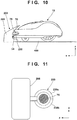
- Fig. 10 is a view showing a state in which the work vehicle 10 has returned to the charging position of the charging ST 200. Referring to Fig. 10 , the internal arrangements of the blade 20 and the work vehicle 10 are not illustrated for descriptive convenience.
- the locking pin holding member 230 is set in a closed state by rotation and driving of the driving motor 225, the locking pin 75 provided at the front end portion of the work vehicle 10 is held by the locking pin holding member 230.
- Fig. 11 is a view illustrating a state in which the locking pin holding member 230 holds the locking pin 75.
- the locking pin holding member 230 is formed from two members 230a and 230b openable by the driving motor 225. When one member 230a performs the closing operation in the clockwise direction, the other member 230b performs the closing operation in the counterclockwise direction. In a state in which the locking pin holding member 230 is kept closed, an annular closed region shown in Fig. 11 is formed, and the locking pin 75 is held in this region, thereby locking the work vehicle 10 to the charging ST 200.
- the members 230a and 230b must be opened such that the locking pin holding member 230 in the closed state shown in Fig. 11 is opened. Until the next work schedule execution start timing or the correct authentication information (PIN code) is input, the charging station ECU 210 maintains the locked state (closed state).
- the charging station ECU 210 can be connected to an external communication device (for example, a smartphone) 350 via an I/O and a network 302 functioning as a communication interface.
- an external communication device for example, a smartphone
- the user can input the authentication information (PIN code) from the communication device 350. If the input of the correct authentication information (PIN code) is confirmed, the ECU 44 controls driving of the driving motor 225 to open the members 230a and 230b, thereby releasing the locked state.
- the anti-theft function can be improved by the physical locking between the work vehicle 10 and the charging ST 200. That is, the autonomous work vehicle can be locked to the charging station for anti-theft performance.
- an arrangement of the charging station 200 which includes a cover member 300 which covers at least the upper portion of the work vehicle 10 and a lid member 330 provided rotatable with respect to the cover member 300 to cover the rear portion of the work vehicle 10 in a state in which a work vehicle 10 is located at the charging operation will be described below.
- Fig. 12 shows views of a state in which the work vehicle 10 has returned to the charging position of the charging ST 200.
- the internal arrangements of a blade 20 and the work vehicle 10 will not be illustrated for descriptive convenience.
- the cover member 300 which covers at least the upper portion of the work vehicle 10 is provided in the charging ST 200.
- the lid member 330 is supported at the end portion of the cover member 300 via a hinge 305.
- 12A of Fig. 12 indicates an open state of the lid member 330
- 12B of Fig. 12 indicates the closed state of the lid member 330.
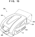
- Fig. 13 is a view exemplifying the outline of the cover member 300 and the lid member 330 which cover the work vehicle 10.
- the charging ST 200 includes the cover member 300 which covers at least the upper portion of the work vehicle 10.
- the arrangement of the cover member 300 is not limited to this.
- the cover member is arranged to cover the upper portion and right and left portions of the work vehicle 10.
- the lid member 330 rotatably supported by the hinge 305 is provided at the end portion of the cover member 300.
- the lid member 330 can be formed from a platelike or rod-like member.
- a driving motor is provided for the hinge 305 to open/close the lid member 330, and the lid member 330 is opened/closed along a track indicated by a broken line by driving of a driving motor.
- Fig. 14 is a block diagram showing the electrical arrangement of the charging station (ST) 200 according to the third embodiment.
- the charging ST 200 includes the charger 205 connected to a power supply 202 via an electrical outlet 204.
- the charging terminal 208 of the charging ST 200 is connected to a charging terminal 34 of the work vehicle 10.
- An AC/DC converter 206 performs the conversion operation based on control of a charging station ECU 210.
- the charging station ECU 210 controls driving of a driving motor 320 to close the lid member 330.
- the lid member 330 is set in a closed state, the work vehicle 10 cannot be moved backward.
- the charging terminal 34 of the work vehicle 10 In a state in which the charging terminal 34 of the work vehicle 10 is in contact with the charging terminal 208 of the charging station 200, the work vehicle 10 cannot be moved in the right-and-left direction. Since the upper portion of the work vehicle 10 is covered with the cover member 300, the work vehicle 10 cannot be moved vertically, either. That is, the movement of the work vehicle 10 is restricted in the front-and-rear direction, the vertical direction, and the right-and-left direction. The work vehicle 10 is locked on the charging ST 200.
- the lid member 330 To release locking of the lid member 330, the lid member 330 must be set in an open state. Until the next work schedule execution start timing or the correct authentication information (PIN code) is input, the charging station ECU 210 maintains the locked state by the lid member 330. For example, if the input of the correct authentication information (PIN code) via the external communication device such as a smartphone is confirmed, the charging station ECU 210 controls driving of the driving motor 320 to open the lid member 330, thereby releasing the locked state.
- the anti-theft function can be improved by the physical locking between the work vehicle 10 and the charging ST 200. That is, the autonomous work vehicle can be locked to the charging station for anti-theft performance.
- a charging station 200 includes a wheel locking mechanism 430 for locking the wheels of a work vehicle 10 in a state in which the work vehicle 10 is located at the charging position will be described below.
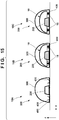
- Fig. 15 shows views for explaining the wheel locking mechanism 430 provided on a base surface 400 of the charging ST 200.
- 15A of Fig. 15 indicates the schematic arrangement of the charging ST 200 when viewed from the y-z plane.
- 15B and 15C of Fig. 15 are schematic views showing a state in which the work vehicle 10 has returned to the charging position of the charging ST 200.
- the internal arrangements of a blade 20 and the work vehicle 10 are not illustrated for descriptive convenience.
- a cover member 300 is arranged to cover the upper portion and the right and left side portions of the work vehicle 10. The arrangement of the lid member is not illustrated to readily understand the description.
- Fig. 16 is a block diagram showing the electrical arrangement of the charging station (ST) 200 according to the fourth embodiment.
- the charging ST 200 includes a charger 205 connected to a power supply 202 via an electrical outlet 204.
- the charging terminal 208 of the charging ST 200 is connected to a charging terminal 34 of the work vehicle 10.
- An AC/DC converter 206 starts the conversion operation based on control of a charging station ECU 210.
- the charging station ECU 210 Upon detecting the start of the conversion operation by the AC/DC converter 206, the charging station ECU 210 controls driving of a driving motor 420 so as to lock the wheels (rear wheels 16) of the work vehicle 10 by the wheel locking mechanism 430.
- the charging ST 200 of this embodiment includes a wheel locking mechanism 430 on the base surface 400 of the charging ST 200 to lock the wheels (rear wheels 16) of the work vehicle 10.
- the wheel locking mechanism 430 is formed from two pawl members openable by the driving motor 420. When the pawl members are closed, the wheels (rear wheels 16) of the work vehicle 10 are locked. When the pawl members are opened, the locking is released.
- one pawl member can perform the opening/closing operation in one direction based on rotation and driving of the driving motor 420.
- the other pawl member can perform the opening/closing operation by reversing the rotational direction of the driving motor 420 via, for example, gears.
- the other pawl member performs the closing operation in the counterclockwise direction, thereby locking the wheels (rear wheels 16).
- the other pawl member performs the opening operation in the clockwise direction, thereby releasing locking of the wheels (rear wheels 16).
- the opening/closing operation of the wheel locking mechanism 430 is not limited to the above example.
- the two pawl members may be opened/closed using the biasing force of an elastic member such as a spring, or various mechanisms for transmitting the rotation of a motor may be used.
- the wheel locking mechanism 430 is set in an open state, and the wheels (rear wheels 16) of the work vehicle 10 are not locked.
- the wheel locking mechanism 430 is set in a closed state, and the wheels (rear wheels 16) of the work vehicle 10 are kept locked.
- Fig. 15 exemplifies the arrangement for locking the rear wheels 16 of the work vehicle 10.
- front wheels 14 of the work vehicle 10 may be locked by the wheel locking mechanism 430 to restrict the movement of the work vehicle 10 in the front-and-rear direction, the vertical direction, and the right-and-left direction. Accordingly, the work vehicle 10 is locked to the charging ST 200.
- the wheel locking mechanism 430 To release locking by the wheel locking mechanism 430, the wheel locking mechanism 430 must be set in an open state. Until the next work schedule execution start timing or the correct authentication information (PIN code) is input, the charging station ECU 210 maintains the locked state by the wheel locking mechanism 430. If the input of the correct authentication information (PIN code) is confirmed, the charging station ECU 210 controls driving of a driving motor 320 to set the wheel locking mechanism 430 in an open state, thereby releasing the locked state.
- the anti-theft function can be improved by the physical locking between the work vehicle 10 and the charging ST 200. That is, the autonomous work vehicle can be locked to the charging station for anti-theft performance.
- Fig. 17 is a flowchart for explaining the processing sequence of the ECU 44 and the charging station ECU 210.
- step S1701 a work vehicle 10 executes the work based on the work schedule preset by the user.
- step S1702 the ECU 44 of the work vehicle 10 determines whether all the scheduled works are complete. If all the scheduled works are not complete (NO in step S1702), the process returns to step S1701 to continue the work.
- step S1702 if it is determined whether all the scheduled works are complete (YES in step S1702), the ECU 44 controls the movement of the work vehicle 10 to return the work vehicle 10 to a charging ST 200 in step S1703.
- step S1704 if the work vehicle 10 returns to the charging ST 200 and a charging terminal 34 of the work vehicle 10 is connected to a charging terminal 208 of the charging station 200, the charging station 200 starts charging.
- step S1705 the ECU 44 or the charging station ECU 210 locks the autonomous work vehicle to the charging station for anti-theft performance by the locking operation described with reference to the first to fourth embodiments while charging of the work vehicle is started in step S1704.
- step S1706 if the ECU 44 or the charging station ECU 210 manages the next work schedule execution start timing stored in the internal memory, and the next work schedule execution start timing is set (YES in step S1706), the ECU 44 or the charging station ECU 210 releases locking in step S1707.
- step S1708 the ECU 44 or the charging station ECU 210 determines whether the correct authentication information (PIN code) is input.
- step S1708 If it is determined in step S1708 that the correct authentication information (PIN code) is not input (NO in step S1708), the process returns to step S1705.
- the ECU 44 or the charging station ECU 210 continues the locked state for anti-theft performance.
- step S1708 determines whether the correct authentication information (PIN code) is input (YES in step S1708). If it is determined in step S1708 that the correct authentication information (PIN code) is input (YES in step S1708), the process advances to step S1707.
- the ECU 44 or the charging station ECU 210 releases the locked state.
- step S1709 the work vehicle 10 executes the work based on the next work schedule preset by the user.
- the locked state can be released or continued based on the start of the preset work vehicle work schedule execution or the input of the correct authentication information (PIN code) while the autonomous work vehicle is locked to the charging station for anti-theft performance.
- the autonomous work vehicle can be locked to the charging station for anti-theft performance.
- the locked state can be released or continued based on the start of the preset work vehicle work schedule execution or the input of the correct authentication information (PIN code) while the autonomous work vehicle is locked to the charging station for anti-theft performance.
Description
- The present invention relates to a lawn ground management system including an autonomous work vehicle for performing a mowing operation by a work unit while autonomously traveling in a work area and a charging station for supplying power to the autonomous work vehicle.
- European Patent Application Publication No.
EP2894532 discloses a system including a base station and an autonomous robot device having an arrangement for cleaning a camera sensor. -
U.S. Patent No. 7614207 discloses an arrangement for holding a lawn mower during transportation. DocumentsEP 2 960 100 A2 andDE 20 2012 104646 U1 - However, in the above patent literatures, an efficient anti-theft arrangement for locking an autonomous work vehicle to a charging station is not disclosed.
- The present invention has been made in consideration of the above problem and provides an anti-theft lawn ground management system capable of locking an autonomous work vehicle to a charging station.
- The present invention provides a lawn ground management system as specified in
claims 1 to 9. - According to the present invention, it is possible to lock the autonomous work vehicle to the charging station for anti-theft performance.
-
Fig. 1 is a view showing the arrangement of an autonomous work vehicle (work vehicle) according to the first embodiment; -
Fig. 2 is a block diagram showing the relationship between the inputs and outputs of an electronic control unit (ECU) for controlling a work vehicle; -
Fig. 3 is a block diagram showing the electrical arrangement of a charging station (charging ST); -
Fig. 4 is a view showing the schematic outer appearance of the charging ST; -
Fig. 5 shows views for explaining the arrangement of a locking member; -
Fig. 6 shows views showing states in which the work vehicle of the first embodiment returns to the charging position of the charging ST; -
Fig. 7 is a view showing the arrangement of a work vehicle according to the second embodiment; -
Fig. 8 is a block diagram showing the electrical arrangement of the charging ST according to the second embodiment; -
Fig. 9 is a view showing the schematic outer appearance of the charging ST according to the second embodiment -
Fig. 10 is a view showing a state in which the work vehicle according to the second embodiment returns to the charging position of the charging ST; -
Fig. 11 is a view exemplifying a state in which a locking pin holding member holds a locking pin; -
Fig. 12 shows views showing a state in which a work vehicle according to the third embodiment returns to the charging position of a charging ST; -
Fig. 13 is a view exemplifying the schematic arrangement of a cover member and a lid member which cover the work vehicle; -
Fig. 14 is a block diagram showing the electrical arrangement of the charging ST according to the third embodiment; -
Fig. 15 shows views for explaining a wheel locking mechanism arranged in the charging ST; -
Fig. 16 is a block diagram showing the electrical arrangement of a charging ST according to the fourth embodiment; and -
Fig. 17 is a flowchart showing the processing sequence of each ECU according to the fifth embodiment. - An embodiment of a lawn ground management system according to the present invention will be exemplified with reference to the accompanying drawings. The lawn ground management system includes an autonomous work vehicle for performing a mowing operation by a work unit while autonomously traveling in a work area, and a charging station for supplying power to the autonomous work vehicle. The work unit for performing the mowing operation includes, for example, a mowing blade (rotary blade), an electric motor for rotating and driving the blade, a blade height adjustment motor for adjusting the height of the blade, a sensor for detecting the height of the blade, and the like.
- The constituent elements described in the following embodiment are merely examples. The technical scope of the present invention is defined by the scope of the appended claims and is not limited by the individual embodiments to be described below.
- A lawn ground management system includes an anti-theft locking portion for locking an autonomous work vehicle to a charging station in a state in which the autonomous work vehicle is located at a charging position to receive the power supply from the charging station.
-
Fig. 1 is a view showing the arrangement of an autonomous work vehicle according to the first embodiment.Fig. 2 is a block diagram showing the relationship between the inputs and outputs of an electronic control unit (ECU) for controlling the autonomous work vehicle. In the following description, a traveling direction (vehicle longitudinal direction) of the autonomous work vehicle when viewed from the side, a lateral direction (vehicle width direction) perpendicular to the traveling direction, and a vertical direction perpendicular to the traveling direction and the lateral direction are defined as a front-and-rear direction, a right-and-left direction, and a vertical direction, respectively. The arrangements of the respective components will be described in accordance with the above definitions. -
Reference numeral 10 inFig. 1 denotes an autonomous work vehicle (to be referred to as a work vehicle hereinafter). Thework vehicle 10 practically functions as an autonomous lawn mower. Avehicle body 12 of thework vehicle 10 includes achassis 12a and aframe 12b attached to thechassis 12a. - The
work vehicle 10 includes two small-diameter left and rightfront wheels 14 fixed to the front side of thechassis 12a via astay 13 in the front-and-rear direction. Thework vehicle 10 also includes large-diameter left and rightrear wheels 16 attached to thechassis 12a in the rear side. - A mowing operation blade (rotary blade) 20 is attached near the central position of the
chassis 12a of thework vehicle 10. An electric motor (to be referred to as a work motor hereinafter) 22 is arranged above theblade 20. Theblade 20 is connected to thework motor 22 and rotated and driven by thework motor 22. - A
motor holding member 23 holds thework motor 22. Themotor holding member 23 is restricted to rotate withrespect chassis 12a and is allowed to move vertically by a combination of, for example, a guide rail and a slider vertically movable by being guided along the guide rail. - A blade
height adjustment motor 100 for adjusting the height of theblade 20 in the vertical direction with respect to a ground surface GR is arranged in thework vehicle 10. Atranslation mechanism 101 for converting the rotation of theheight adjustment motor 100 into the translation in the vertical direction is connected to the blade height adjustment motor (to be referred to as a height adjustment motor hereinafter) 100. Amotor holding member 23 for holding thework motor 22 is connected to thetranslation mechanism 101. - The
translation mechanism 101 converts the rotation of theheight adjustment motor 100 into the translation (movement in the vertical direction), and the translation is transmitted to themotor holding member 23. Thework motor 22 held by themotor holding member 23 is translated (movement in the vertical direction) by the translation (movement in the vertical direction) of themotor holding member 23. By the movement of thework motor 22 in the vertical direction, the height of theblade 20 with respect to the ground surface GR can be adjusted. - Two electric motors (motors; to be referred to as traveling motors hereinafter) 26 are attached to the
chassis 12a of the work vehicle 10 (Fig. 2 ). Thetraveling motors 26 are connected to the left and rightrear wheels 16, respectively. Thefront wheels 14 serve as driven wheels, and therear wheels 16 serve as the driving wheels. The right wheels and the left wheels are independently rotated in the forward direction (rotation in the forward direction) or in the reverse direction (rotation in the reverse direction), thereby moving thework vehicle 10 in a variety of directions. An ECU 44, various types of sensors S, acharging unit 30, and abattery 32 to control the operations of theblade 20, thework motor 22, thetraveling motors 26, theheight adjustment motor 100, and thework vehicle 10 are covered by theframe 12b. - The
charging unit 30 and thebattery 32 are mounted in thework vehicle 10. Acharging terminal 34 is provided at the front end position of theframe 12b in the front-and-rear direction. Thecharging terminal 34 is connected to thecharging unit 30 via a cable, and thecharging unit 30 is connected to thebattery 32. Thework motor 22, thetraveling motors 26, and theheight adjustment motor 100 are connected to thebattery 32 and are powered from thebattery 32. - The electronic control unit (control device; Electronic Control Unit; to be referred to as an ECU hereinafter) 44 formed from a microcomputer provided on a circuit board is mounted in the
work vehicle 10. As shown inFig. 2 , theECU 44 includes aCPU 44a, an I/O 44b, and a memory (ROM, EEPROM, or RAM) 44c. Thememory 44c stores information on the work schedule of thework vehicle 10, various kinds of programs for controlling the operation of thework vehicle 10, and a PIN code as authentication information for authenticating an authentic user. - In a state in which the autonomous work vehicle is locked to the charging station for anti-theft performance, the
ECU 44 controls the locked state release or continuation based on the inputs of the preset work schedule of the work vehicle or the authentication information (PIN code). For example, theECU 44 manages the next work schedule execution start timing stored in the internal memory and releases the locked state at the next work schedule execution start timing. Alternatively, if the next work schedule execution start timing is not set, but the correct authentication information (PIN code) is input, theECU 44 can release the locked state. TheECU 44 determines whether the authentication information (PIN code) stored in thememory 44c matches the PIN code input from an input device or the like. If the PIN codes match, theECU 44 determines the input from the authentic user. TheECU 44 releases the locked state for anti-theft performance to be described below and sets thework vehicle 10 in a workable state. - As sensors for obtaining position information of the
work vehicle 10, for example, adirection sensor 46 for detecting the direction corresponding to the terrestrial magnetism and aGPS sensor 48 for detecting information indicating the current position (latitude and longitude) of thework vehicle 10 upon reception of radio waves from a GPS satellite are connected to theECU 44. - As sensors for obtaining information on the moving state of the
work vehicle 10, for example, awheel speed sensor 50 for detecting the wheel speeds of the left and rightrear wheels 16, anangular velocity sensor 52 for detecting an angular velocity around a vertical axis (the z-axis in the vertical direction) of the barycentric position of thework vehicle 10, and anacceleration sensor 54 for detecting accelerations in the orthogonal three axes, that is, x-, y-, and z-axes acting on thework vehicle 10 are connected to theECU 44. - A
lift sensor 60 for outputting an ON signal when thework vehicle 10 is lifted is connected to thework vehicle 10. Thework vehicle 10 is protected by the authentication information (PIN code). TheECU 44 can determine based on the authentication information (PIN code) whether the user is an authentic user of thework vehicle 10. If the correct authentication information (PIN code) is not input and thework vehicle 10 is lifted, thelift sensor 60 outputs the ON signal. When thelift sensor 60 outputs the ON signal, theECU 44 controls analarm unit 35 until the authentication information is input. Thealarm unit 35 generates a beep sound as an anti-theft alarm sound of thework vehicle 10. - A
current sensor 62 for detecting current consumption (power consumption) of the mountedbattery 32 is connected to theECU 44. The detection result of the current consumption (power consumption) is stored in thememory 44c of theECU 44. If a predetermined current is consumed and the power accumulated in thebattery 32 is equal to or smaller than a threshold, theECU 44 controls so that thework vehicle 10 returns to a charging station (charging ST) 200 for charging. The arrangement of the charging station 200 (charging ST) will be described later. - A
blade height sensor 64 for detecting the height of theblade 20 with respect to the ground surface GR, that is, the height of theblade 20 with respect to theframe 12b is provided in thework vehicle 10. The detection result of theblade height sensor 64 is input to theECU 44. When theheight adjustment motor 100 is driven based on the control of theECU 44, theblade 20 is vertically moved to adjust the height from the ground surface GR. - As an arrangement for inputting a user command to the
frame 12b of thework vehicle 10, for example, aninput device 33 such as a touch panel and adisplay 36 are arranged. The user can input authentication information (PIN code) from theinput device 33. Theinput device 33 and thedisplay 36 are connected to theECU 44. Various kinds of information such as the work mode and setting information of thework vehicle 10 can be displayed on thedisplay 36 in accordance with a command from theECU 44. - As shown in
Fig. 2 , outputs from the various types of sensors S are sent to theECU 44 and input via the I/O 44b. TheECU 44 supplies power from thebattery 32 to the travelingmotors 26, thework motor 22, and theheight adjustment motor 100 based on the outputs from the various types of sensors S. TheECU 44 controls traveling of thework vehicle 10 by outputting a control value via the I/O 44b and controlling the operations of the travelingmotors 26, adjusts the height of theblade 20 by controlling theheight adjustment motor 100, and controls rotation of theblade 20 by controlling thework motor 22. In this case, the I/O 44b functions as a communication interface and can be connected to an external communication device (for example, a smartphone) 350 via anetwork 302. For example, the user can input authentication information (PIN code) from thecommunication device 350. -
Fig. 3 is a block diagram showing the electrical arrangement of the charging station (charging ST) 200. As shown inFig. 3 , the chargingST 200 includes a charger (charging stand) 205 connected to apower supply 202 via anelectrical outlet 204. - The
charger 205 includes an AC/DC converter 206, a chargingterminal 208, and a charging station ECU (Electronic Control Unit) 210 formed from a microcomputer for controlling the operation of the AC/DC converter 206. As in theECU 44 described with reference toFig. 2 , the charging station ECU (Electronic Control Unit) 210 includes a CPU, an I/O, and a memory (ROM, EEPROM, or RAM). Information on the work schedule of thework vehicle 10 and a PIN code about a user are stored in the memory of the chargingstation ECU 210. - In a state in which the autonomous work vehicle is locked to the charging station for anti-theft performance, the charging
station ECU 210 can control release or continuation of the locked state based on the input of the preset work schedule of the work vehicle or the authentication information (PIN code). - For example, the charging
station ECU 210 manages the next work schedule execution start timing stored in the internal memory and releases the locked state at the next work schedule execution start timing. Alternatively, if the next work schedule execution start timing is not set, but the correct authentication information (PIN code) is input, the chargingstation ECU 210 can release the locked state. - When the
work vehicle 10 returns to the charging position connected to the charger 205 (charging terminal 208) of the chargingST 200, the chargingterminal 208 of the chargingST 200 is connected to the chargingterminal 34 of thework vehicle 10. The conversion operation by the AC/DC converter 206 is started based on the control of the charging station ECU (Electronic Control Unit) 210. Upon detecting the start of the converting operation by the AC/DC converter 206, the chargingstation ECU 210 communicates with theECU 44 of thework vehicle 10 to transmit a locking instruction, thereby starting the locking operation. Based on the reception of the locking instruction, theECU 44 of thework vehicle 10 controls the operation of the bladeheight adjustment motor 100 and the position of theblade 20, thereby performing the locking operation. The detailed contents of the locking operation will be described later. - An AC voltage sent from the
power supply 202 to theelectrical outlet 204 in the chargingST 200 is transformed into a DC voltage in the AC/DC converter 206 of thecharger 205. The DC voltage is supplied to the chargingterminal 208. When thework vehicle 10 returned to the chargingST 200 is connected (docked) to the chargingterminal 208 of the chargingST 200 via the chargingterminal 34, thebattery 32 of thework vehicle 10 is charged with the voltage supplied via the chargingterminal 208 and the chargingterminal 34. -
Fig. 4 is a view showing the schematic outer appearance of the chargingST 200. Referring toFig. 4 , the arrangement of thecharger 205 is shown in the block diagram ofFig. 3 . Theblade 20 of thework vehicle 10 is locked and a lockingmember 220 for locking thework vehicle 10 to the chargingST 200 for anti-theft performance is fixed to abase surface 400 of the chargingST 200. Referring toFig. 4 , theblade 20 shows that the position of theblade 20 is supplementarily shown when thework vehicle 10 returns to the charging position connected to thecharger 205 of the chargingST 200. -
Fig. 5 shows views for explaining the arrangement of the lockingmember 220. For the descriptive convenience, the arrangement of thecharger 205 is not illustrated. 5A ofFig. 5 shows the arrangement of the x-y plane of thebase surface 400 of the chargingST 200. 5B ofFig. 5 shows the arrangement of the x-z plane of thebase surface 400. 5C ofFig. 5 shows the arrangement of the y-z plane of thebase surface 400. The locking member is formed from two portions (members blade 20 passes when the autonomous work vehicle returns from the work area to the charging station, and a second member interval W2 through which the blade does not pass in a state in which the autonomous work vehicle is located at the charging position. - In 5A of
Fig. 5 , theblade 20 indicated by the broken line indicates the position of theblade 20 during which thework vehicle 10 returns to the chargingST 200. Based on the control of the ECU 440, thework vehicle 10 travels in a direction indicated by an arrow and returns to the charging position where the chargingterminal 34 of thework vehicle 10 is connected to the charger 205 (charging terminal 208) of the chargingST 200. In 5A ofFig. 5 , theblade 20 indicated by a solid line indicates the position of theblade 20 in a state in which thework vehicle 10 returns to the charging position. - The
members blade 20, the relationship between the member intervals W1 and W2, and D satisfies W1 > D > W2. - As shown in 5B and 5C of
Fig. 5 , as the height of themembers base surface 400, themembers Fig. 5 , the member height H2 indicates a representative height of the members corresponding to the central portion of theblade 20 returned to the charging position. - In 5B and 5C of
Fig. 5 , theblade 20 indicated by the broken line indicates the position of theblade 20 while thework vehicle 10 is returning to the chargingST 200. In 5B ofFig. 5 , theblade 20 indicated by an alternate long and short dashed line indicates the position of theblade 20 in a state in which thework vehicle 10 has returned to the charging position. - The
work vehicle 10 includes theblade height sensor 64 for detecting the height of theblade 20 with respect to the ground surface GR, theheight adjustment motor 100 serving as an adjustment unit for adjusting the height of theblade 20, and theECU 44 serving as a control unit for controlling the height of theblade 20 by theheight adjustment motor 100 based on the detection result of theblade height sensor 64. - The
ECU 44 controls theblade 20 to the first height (for example, a height h1 lower than HI in 5C ofFig. 5 ) when theblade 20 passes between the members (220a and 220b) having the first member interval W1 of thelocking members ECU 44 moves theblade 20 upward to the second height (for example, a height h2 higher than HI in 5C ofFig. 5 but lower than H2) higher than the first height h1 by controlling theheight adjustment motor 100 in order to make theblade 20 come close to themembers work vehicle 10 is located at the charging position. This makes it possible to lock theblade 20 to the lockingmember 220. - More specifically, the
ECU 44 controls driving of theheight adjustment motor 100 so as to make theblade 20 pass through the ends of the members (220a and 220b) at the first member interval W1 and the member height HI while thework vehicle 10 is returning to the chargingST 200, thereby performing the height adjustment (height position control of the blade 20) of theblade 20 with respect to thebase surface 400. For example, theECU 44 can perform height position control for controlling the height to match the lowest height h1 among the adjustable heights by theheight adjustment motor 100. - In a state in which the
work vehicle 10 has returned to the charging position, theECU 44 controls driving of theheight adjustment motor 100 so as to move theblade 20 upward to come close to themembers Fig. 5 ). For example, theECU 44 can perform height position control for controlling the height to match the highest height h2 among the adjustable heights by theheight adjustment motor 100. -
Fig. 6 shows views of a state in which thework vehicle 10 has returned to the charging position of the chargingST 200. In 6A ofFig. 6 , the height of theblade 20 corresponds to a state of theblade 20 indicated by the alternate long and short dashed line in 5B ofFig. 5 (the height of theblade 20 is h1). - In the state indicated by 6A of
Fig. 6 , theECU 44 controls driving of theheight adjustment motor 100 so as to move theblade 20 upward to the height h2 to make theblade 20 come close to themembers Fig. 5 . More specifically, theECU 44 controls driving of theheight adjustment motor 100 so as to increase theblade 20 to the highest mowing height. In 6B ofFig. 6 , the height of theblade 20 corresponds to the height of theblade 20 indicated by the solid line in 5B and 5C ofFig. 5 . - Since the charging
ST 200 is fixed on the ground by an earth screw to which an earth terminal connected to an earth cable is attached, it is difficult to lift the chargingST 200. That is, it is difficult to remove the earth screw in a state in which thework vehicle 10 is located on the chargingST 200. In a state in which theblade 20 is lifted to the highest mowing height, the movement of thework vehicle 10 in the front-and-rear direction, the vertical direction, and the right-and-left direction is restricted because the member interval W2 of thelocking members blade 20. That is, thework vehicle 10 is locked on the chargingST 200. - To release the locked state, the
blade 20 must be moved downward to a position (for example, the height h1) lower than the height HI (5C ofFig. 5 ). Until the next work schedule execution start timing or the correct authentication information (PIN code) is input, theECU 44 maintains the locked state. - If the input of the correct authentication information (PIN code) is confirmed, the
ECU 44 controls driving of theheight adjustment motor 100 to move theblade 20 downward from the second height h2 shown in 5C ofFig. 5 to the first height h1, thereby releasing locking of thelock members 220. Alternatively, theECU 44 moves theblade 20 downward from the second height h2 to the first height h1 at the work schedule execution start timing, thereby releasing locking of the lock member. - According to this embodiment, the anti-theft function can be improved by the physical locking between the
work vehicle 10 and the chargingST 200. That is, the autonomous work vehicle can be locked to the charging station for anti-theft performance. - The arrangement of the second embodiment of the present invention will be described with reference to
Figs. 7 to 11 . In this embodiment, as the arrangement of the locking portion, an arrangement including alocking pin 75 provided at the front end portion of awork vehicle 10, and a lockingpin holding member 230 provided in a chargingstation 200 to hold the lockingpin 75 in a state in which thework vehicle 10 is located at the charging position will be described below. -
Fig. 7 is a view showing the arrangement of thework vehicle 10 according to the second embodiment. The components as in thework vehicle 10 described in the first embodiment denote the same parts in the second embodiment, and a description thereof will be omitted. In thework vehicle 10 according to this embodiment, arecess 70 is formed at the front end portion. The lockingpin 75 is arranged in therecess 70. -
Fig. 8 is a block diagram showing the electrical arrangement of the charging station (ST) 200 according to the second embodiment. As shown inFig. 8 , the chargingST 200 includes acharger 205 connected to apower supply 202 via anelectrical outlet 204. - The
charger 205 includes an AC/DC converter 206, a chargingterminal 208, and a charging station ECU (Electronic Control Unit) 210 for controlling the operation of the AC/DC converter 206. When thework vehicle 10 returns to the charging position connected to the charger 205 (charging terminal 208) of the chargingstation 200, the chargingterminal 208 of the chargingST 200 is connected to a chargingterminal 34 of thework vehicle 10. The AC/DC converter 206 starts the conversion operation based on the control of the chargingstation ECU 210. - Upon detecting the start of the conversion operation of the AC/
DC converter 206, the chargingstation ECU 210 controls driving of a drivingmotor 225 to operate the lockingpin holding member 230 for locking thework vehicle 10 to the chargingST 200 for anti-theft performance. -
Fig. 9 is a view showing the schematic outer appearance of the chargingST 200 according to the second embodiment. Referring toFig. 9 , the arrangement of thecharger 205 is the same as that shown in the block diagram ofFig. 8 . A lockingmember 220 described with reference to the first embodiment is fixed to abase surface 400 of the chargingST 200. Ablade 20 supplementarily indicates the position of theblade 20 when thework vehicle 10 returns to the charging position. - Referring to
Fig. 9 , the lockingpin holding member 230 is formed from two pawl members capable of being opened/closed by the drivingmotor 225. For example, one pawl member performs the opening/closing operation in one direction based on rotation and driving of the drivingmotor 225. For example, the other pawl member performs the opening/closing operation when the rotation direction of the drivingmotor 225 is reversed via gears. When one pawl member performs the closing operation in the clockwise direction, the other pawl member performs the closing operation in the counterclockwise direction. Similarly, for example, when one pawl member performs the opening operation in the counterclockwise direction, the other pawl member performs the opening operation in the clockwise direction. Note that the opening/closing operation of the lockingpin holding member 230 is not limited to this. For example, the two pawl members may be opened/closed using the biasing force of an elastic member such as a spring, or various mechanisms for transmitting rotation of a motor may be used. -
Fig. 10 is a view showing a state in which thework vehicle 10 has returned to the charging position of the chargingST 200. Referring toFig. 10 , the internal arrangements of theblade 20 and thework vehicle 10 are not illustrated for descriptive convenience. In a state in which thework vehicle 10 has returned to the chargingST 200, when the lockingpin holding member 230 is set in a closed state by rotation and driving of the drivingmotor 225, the lockingpin 75 provided at the front end portion of thework vehicle 10 is held by the lockingpin holding member 230. -
Fig. 11 is a view illustrating a state in which the lockingpin holding member 230 holds the lockingpin 75. The lockingpin holding member 230 is formed from twomembers motor 225. When onemember 230a performs the closing operation in the clockwise direction, theother member 230b performs the closing operation in the counterclockwise direction. In a state in which the lockingpin holding member 230 is kept closed, an annular closed region shown inFig. 11 is formed, and the lockingpin 75 is held in this region, thereby locking thework vehicle 10 to the chargingST 200. - When one
member 230a performs the opening operation in the counterclockwise direction, theother member 230b performs the opening operation in the clockwise direction. By this opening operation, the lockingpin holding member 230 is set in an open state (Fig. 9 ), thereby releasing locking. - To release locking, the
members pin holding member 230 in the closed state shown inFig. 11 is opened. Until the next work schedule execution start timing or the correct authentication information (PIN code) is input, the chargingstation ECU 210 maintains the locked state (closed state). - The charging
station ECU 210 can be connected to an external communication device (for example, a smartphone) 350 via an I/O and anetwork 302 functioning as a communication interface. For example, the user can input the authentication information (PIN code) from thecommunication device 350. If the input of the correct authentication information (PIN code) is confirmed, theECU 44 controls driving of the drivingmotor 225 to open themembers work vehicle 10 and the chargingST 200. That is, the autonomous work vehicle can be locked to the charging station for anti-theft performance. - The arrangement of the third embodiment of the present invention will now be described with reference to
Figs. 12 to 14 . In this embodiment, as the arrangement of a locking portion, an arrangement of the chargingstation 200 which includes acover member 300 which covers at least the upper portion of thework vehicle 10 and alid member 330 provided rotatable with respect to thecover member 300 to cover the rear portion of thework vehicle 10 in a state in which awork vehicle 10 is located at the charging operation will be described below. -
Fig. 12 shows views of a state in which thework vehicle 10 has returned to the charging position of the chargingST 200. The internal arrangements of ablade 20 and thework vehicle 10 will not be illustrated for descriptive convenience. Thecover member 300 which covers at least the upper portion of thework vehicle 10 is provided in the chargingST 200. Thelid member 330 is supported at the end portion of thecover member 300 via ahinge 305. 12A ofFig. 12 indicates an open state of thelid member Fig. 12 indicates the closed state of thelid member 330. -
Fig. 13 is a view exemplifying the outline of thecover member 300 and thelid member 330 which cover thework vehicle 10. In this embodiment, the chargingST 200 includes thecover member 300 which covers at least the upper portion of thework vehicle 10. The arrangement of thecover member 300 is not limited to this. The cover member is arranged to cover the upper portion and right and left portions of thework vehicle 10. Thelid member 330 rotatably supported by thehinge 305 is provided at the end portion of thecover member 300. Thelid member 330 can be formed from a platelike or rod-like member. A driving motor is provided for thehinge 305 to open/close thelid member 330, and thelid member 330 is opened/closed along a track indicated by a broken line by driving of a driving motor. -
Fig. 14 is a block diagram showing the electrical arrangement of the charging station (ST) 200 according to the third embodiment. As shown inFig. 14 , the chargingST 200 includes thecharger 205 connected to apower supply 202 via anelectrical outlet 204. - When the
work vehicle 10 returns to the charging position connected to a charger 205 (charging terminal 208) of the chargingST 200, the chargingterminal 208 of the chargingST 200 is connected to a chargingterminal 34 of thework vehicle 10. An AC/DC converter 206 performs the conversion operation based on control of a chargingstation ECU 210. - Upon detecting the conversion operation by the AC/
DC converter 206, the chargingstation ECU 210 controls driving of a drivingmotor 320 to close thelid member 330. When thelid member 330 is set in a closed state, thework vehicle 10 cannot be moved backward. In a state in which the chargingterminal 34 of thework vehicle 10 is in contact with the chargingterminal 208 of the chargingstation 200, thework vehicle 10 cannot be moved in the right-and-left direction. Since the upper portion of thework vehicle 10 is covered with thecover member 300, thework vehicle 10 cannot be moved vertically, either. That is, the movement of thework vehicle 10 is restricted in the front-and-rear direction, the vertical direction, and the right-and-left direction. Thework vehicle 10 is locked on the chargingST 200. - To release locking of the
lid member 330, thelid member 330 must be set in an open state. Until the next work schedule execution start timing or the correct authentication information (PIN code) is input, the chargingstation ECU 210 maintains the locked state by thelid member 330. For example, if the input of the correct authentication information (PIN code) via the external communication device such as a smartphone is confirmed, the chargingstation ECU 210 controls driving of the drivingmotor 320 to open thelid member 330, thereby releasing the locked state. According to this embodiment, the anti-theft function can be improved by the physical locking between thework vehicle 10 and the chargingST 200. That is, the autonomous work vehicle can be locked to the charging station for anti-theft performance. - The arrangement of the fourth embodiment of the present invention will now be described with reference to
Figs. 15 and16 . In this embodiment, as the arrangement of a locking portion, an arrangement in which a chargingstation 200 includes awheel locking mechanism 430 for locking the wheels of awork vehicle 10 in a state in which thework vehicle 10 is located at the charging position will be described below. -
Fig. 15 shows views for explaining thewheel locking mechanism 430 provided on abase surface 400 of the chargingST 200. 15A ofFig. 15 indicates the schematic arrangement of the chargingST 200 when viewed from the y-z plane. 15B and 15C ofFig. 15 are schematic views showing a state in which thework vehicle 10 has returned to the charging position of the chargingST 200. The internal arrangements of ablade 20 and thework vehicle 10 are not illustrated for descriptive convenience. Referring toFig. 15 , acover member 300 is arranged to cover the upper portion and the right and left side portions of thework vehicle 10. The arrangement of the lid member is not illustrated to readily understand the description. -
Fig. 16 is a block diagram showing the electrical arrangement of the charging station (ST) 200 according to the fourth embodiment. The chargingST 200 includes acharger 205 connected to apower supply 202 via anelectrical outlet 204. - When the
work vehicle 10 returns to the charging position connected to the charger 205 (charging terminal 208) of the chargingstation 200, the chargingterminal 208 of the chargingST 200 is connected to a chargingterminal 34 of thework vehicle 10. An AC/DC converter 206 starts the conversion operation based on control of a chargingstation ECU 210. - Upon detecting the start of the conversion operation by the AC/
DC converter 206, the chargingstation ECU 210 controls driving of a drivingmotor 420 so as to lock the wheels (rear wheels 16) of thework vehicle 10 by thewheel locking mechanism 430. - As shown in
Fig. 15 , the chargingST 200 of this embodiment includes awheel locking mechanism 430 on thebase surface 400 of the chargingST 200 to lock the wheels (rear wheels 16) of thework vehicle 10. Thewheel locking mechanism 430 is formed from two pawl members openable by the drivingmotor 420. When the pawl members are closed, the wheels (rear wheels 16) of thework vehicle 10 are locked. When the pawl members are opened, the locking is released. - For example, one pawl member can perform the opening/closing operation in one direction based on rotation and driving of the driving
motor 420. The other pawl member can perform the opening/closing operation by reversing the rotational direction of the drivingmotor 420 via, for example, gears. For example, when one pawl member performs the closing operation in the clockwise direction, the other pawl member performs the closing operation in the counterclockwise direction, thereby locking the wheels (rear wheels 16). Similarly, for example, when one pawl member performs the opening operation in the counterclockwise direction, the other pawl member performs the opening operation in the clockwise direction, thereby releasing locking of the wheels (rear wheels 16). - Note that the opening/closing operation of the
wheel locking mechanism 430 is not limited to the above example. For example, the two pawl members may be opened/closed using the biasing force of an elastic member such as a spring, or various mechanisms for transmitting the rotation of a motor may be used. - In 15B of
Fig. 15 , thewheel locking mechanism 430 is set in an open state, and the wheels (rear wheels 16) of thework vehicle 10 are not locked. In 15C ofFig. 15 , thewheel locking mechanism 430 is set in a closed state, and the wheels (rear wheels 16) of thework vehicle 10 are kept locked. - Note that
Fig. 15 exemplifies the arrangement for locking therear wheels 16 of thework vehicle 10. However,front wheels 14 of thework vehicle 10 may be locked by thewheel locking mechanism 430 to restrict the movement of thework vehicle 10 in the front-and-rear direction, the vertical direction, and the right-and-left direction. Accordingly, thework vehicle 10 is locked to the chargingST 200. - To release locking by the
wheel locking mechanism 430, thewheel locking mechanism 430 must be set in an open state. Until the next work schedule execution start timing or the correct authentication information (PIN code) is input, the chargingstation ECU 210 maintains the locked state by thewheel locking mechanism 430. If the input of the correct authentication information (PIN code) is confirmed, the chargingstation ECU 210 controls driving of a drivingmotor 320 to set thewheel locking mechanism 430 in an open state, thereby releasing the locked state. According to this embodiment, the anti-theft function can be improved by the physical locking between thework vehicle 10 and the chargingST 200. That is, the autonomous work vehicle can be locked to the charging station for anti-theft performance. - The processing sequence of an
ECU 44 for releasing locking and a chargingstation ECU 210 when the autonomous work vehicle is locked to the charging station for anti-theft performance will be described below. -
Fig. 17 is a flowchart for explaining the processing sequence of theECU 44 and the chargingstation ECU 210. - In step S1701, a
work vehicle 10 executes the work based on the work schedule preset by the user. In step S1702, theECU 44 of thework vehicle 10 determines whether all the scheduled works are complete. If all the scheduled works are not complete (NO in step S1702), the process returns to step S1701 to continue the work. - On the other hand, if it is determined whether all the scheduled works are complete (YES in step S1702), the
ECU 44 controls the movement of thework vehicle 10 to return thework vehicle 10 to a chargingST 200 in step S1703. - In step S1704, if the
work vehicle 10 returns to the chargingST 200 and a chargingterminal 34 of thework vehicle 10 is connected to a chargingterminal 208 of the chargingstation 200, the chargingstation 200 starts charging. - In step S1705, the
ECU 44 or the chargingstation ECU 210 locks the autonomous work vehicle to the charging station for anti-theft performance by the locking operation described with reference to the first to fourth embodiments while charging of the work vehicle is started in step S1704. - In step S1706, if the
ECU 44 or the chargingstation ECU 210 manages the next work schedule execution start timing stored in the internal memory, and the next work schedule execution start timing is set (YES in step S1706), theECU 44 or the chargingstation ECU 210 releases locking in step S1707. - On the other hand, if the next work schedule execution start timing is not set (NO in step S1706), the process advances to step S1708. In step S1708, the
ECU 44 or the chargingstation ECU 210 determines whether the correct authentication information (PIN code) is input. - If it is determined in step S1708 that the correct authentication information (PIN code) is not input (NO in step S1708), the process returns to step S1705. The
ECU 44 or the chargingstation ECU 210 continues the locked state for anti-theft performance. - On the other hand, if it is determined in step S1708 that the correct authentication information (PIN code) is input (YES in step S1708), the process advances to step S1707. The
ECU 44 or the chargingstation ECU 210 releases the locked state. - In step S1709, the
work vehicle 10 executes the work based on the next work schedule preset by the user. - According to this embodiment, the locked state can be released or continued based on the start of the preset work vehicle work schedule execution or the input of the correct authentication information (PIN code) while the autonomous work vehicle is locked to the charging station for anti-theft performance.
-
-
Arrangement 1. A lawn ground management system of the above embodiments is a lawn ground management system including an autonomous work vehicle (for example, 10) configured to perform a mowing operation by a work unit (for example, 20, 22, 64, 100) while autonomously traveling in a work area, and a charging station (for example, 200) configured to perform power supply to the autonomous work vehicle, comprising:
locking means (for example, 220, 75, 230, 300, 330, 430) for locking the autonomous work vehicle to the charging station for anti-theft performance in a state in which the autonomous work vehicle is located at a charging position to receive the power supply. - Arrangement 2. In the lawn ground management system (for example, 10, 200) of the above embodiments, the work unit includes a mowing blade (for example, 20), and the charging station (for example, 200) includes a locking member (for example, 220) configured to lock the blade.
- Arrangement 3. In the lawn ground management system (for example, 10, 200) of the above embodiments, the locking member (for example, 220) includes two portions having a first member interval (for example, W1) capable of passing the blade when the autonomous work vehicle returns from the work area to the charging station and a second member interval (for example, W2) incapable of passing the blade in a state in which the autonomous work vehicle is located at the charging position.
- Arrangement 4. In the lawn ground management system (for example, 10, 200) of the above embodiments, the autonomous work vehicle (for example, 10) includes:
- detection means (for example, 64) for detecting a height of the blade with respect to a ground surface;
- adjustment means (for example, 100, 101) for adjusting the height of the blade; and
- control means (for example, 44) for controlling the height of the blade by the adjustment means based on a detection result of the detection means,
- wherein the control means
- controls the blade to a first height (for example, h1) in the locking member when the blade passes between the members arranged at the first member interval, and
- controls the adjustment means so as to make the blade come close to the members arranged at the second member interval to move the blade (for example, 20) upward to a second height (for example, h2) higher than the first height in a state in which the autonomous work vehicle is located at the charging position, thereby locking the blade (for example, 20) to the locking member (for example, 220).
- Arrangement 5. In the lawn ground management system (for example, 10, 200) of the above embodiments, the control means (for example, 44) moves the blade downward from the second height to the first height to release locking of the locking member (for example, 220) based on an input of correct authentication information.
- Arrangement 6. In the lawn ground management system (for example, 10, 200) of the above embodiments, the control means (for example, 44) moves the blade downward from the second height to the first height to release locking of the locking member (for example, 220) based on a work schedule execution start timing.
- Arrangement 7. In the lawn ground management system (for example, 10, 200) of the above embodiments, the locking means includes:
- a locking pin (for example, 75) provided at a front end portion of the autonomous work vehicle; and
- a locking pin holding member (for example, 230) provided in the charging station and configured to hold the locking pin in a state in which the autonomous work vehicle is located at the charging position.
- Arrangement 8. In the lawn ground management system (for example, 10, 200) of the above embodiments, the charging station (for example, 200) includes:
- a cover member (for example, 300) serving as the locking means and configured to cover at least an upper portion of the autonomous work vehicle in a state in which the autonomous work vehicle is located at the charging position; and
- a lid member (for example, 330) provided rotatable with respect to the cover member and configured to cover a rear portion of the autonomous work vehicle.
- Arrangement 9. In the lawn ground management system (for example, 10, 200) of the above embodiments, the charging station (for example, 200) includes a vehicle wheel locking mechanism (for example, 430) serving as the locking means and configured to lock a vehicle wheel of the autonomous work vehicle in a state in which the autonomous work vehicle is located at the charging position.
-
Arrangement 10. In the lawn ground management system (for example, 10, 200) of the above embodiments, the charging station (for example, 200) is fixed to a ground surface by an earth screw. - According to the lawn ground management systems of
arrangements 1 to 10, the autonomous work vehicle can be locked to the charging station for anti-theft performance. According to the lawn ground management systems of arrangements 5 and 6, the locked state can be released or continued based on the start of the preset work vehicle work schedule execution or the input of the correct authentication information (PIN code) while the autonomous work vehicle is locked to the charging station for anti-theft performance. - While the present invention has been described with reference to exemplary embodiments, it is to be understood that the invention is not limited to the disclosed exemplary embodiments. The scope of the following claims is to be accorded the broadest interpretation so as to encompass all such modifications and equivalent structures and functions.
Claims (9)
- A lawn ground management system including
an autonomous work vehicle (10) configured to perform a mowing operation by a work unit while autonomously traveling in a work area,
wherein the work unit includes a mowing blade (20),
a charging station (200) configured to perform power supply to the autonomous work vehicle, and
a locking means (220, 75, 230, 300, 330, 430) for locking the autonomous work vehicle to the charging station (200) for anti-theft performance in a state in which the autonomous work vehicle (10) is located at a charging position to receive the power supply, and
characterized in
that the charging station (200) includes a locking member (220) configured to lock the blade (20). - The system according to claim 1, wherein
the locking member (220) includes two portions having
a first member interval (W1) capable of passing the blade (20) when the autonomous work vehicle (10) returns from the work area to the charging station (200) and
a second member interval (W2) incapable of passing the blade (20) in a state in which the autonomous work vehicle (10) is located at the charging position. - The system according to claim 2, wherein
the autonomous work vehicle (10) includes:detection means (64) for detecting a height of the blade (20) with respect to a ground surface;adjustment means (100, 101) for adjusting the height of the blade (20); andcontrol means (44) for controlling the height of the blade (20) by the adjustment means (100, 101) based on a detection result of the detection means (64),wherein the control means (44)controls the blade (20) to a first height (h1) in the locking member (220) when the blade (20) passes between the members arranged at the first member interval (W1), andcontrols the adjustment means (100, 101) so as to make the blade (20) come close to the members arranged at the second member interval (W2) to move the blade (20) upward to a second height (h2) higher than the first height in a state in which the autonomous work vehicle (10) is located at the charging position, thereby locking the blade (20) to the locking member (220). - The system according to claim 3, wherein
the control means (44) moves the blade (20) downward from the second height (h2) to the first height (h1) to release locking of the locking member (220) based on an input of correct authentication information. - The system according to claim 4, wherein
the control means (44) moves the blade (20) downward from the second height (h2) to the first height (h1) to release locking of the locking member (220) based on a work schedule execution start timing. - The system according to any one of claims 1 to 5, wherein
the locking means includes:a locking pin (75) provided at a front end portion of the autonomous work vehicle (10); anda locking pin holding member (230) provided in the charging station (200) and configured to hold the locking pin in a state in which the autonomous work vehicle (20) is located at the charging position. - The system according to any one of claims 1 to 6, wherein
the charging station (200) includes:a cover member (300) serving as the locking means and configured to cover at least an upper portion of the autonomous work vehicle (20) in a state in which the autonomous work vehicle (20) is located at the charging position; anda lid member (330) provided rotatable with respect to the cover member (300) and configured to cover a rear portion of the autonomous work vehicle (20). - The system according to any one of claims 1 to 7, wherein
the charging station (200) includes a vehicle wheel locking mechanism (430) serving as the locking means and configured to lock a vehicle wheel of the autonomous work vehicle (20) in a state in which the autonomous work vehicle (20) is located at the charging position. - The system according to any one of claims 1 to 8, wherein
the charging station (200) is fixed to a ground surface by an earth screw to which an earth terminal connected to an earth cable is connected.
Priority Applications (2)
| Application Number | Priority Date | Filing Date | Title |
|---|---|---|---|
| EP18159061.3A EP3533310B1 (en) | 2018-02-28 | 2018-02-28 | Lawn ground management system |
| PCT/JP2019/007690 WO2019168069A1 (en) | 2018-02-28 | 2019-02-27 | Lawn ground management system |
Applications Claiming Priority (1)
| Application Number | Priority Date | Filing Date | Title |
|---|---|---|---|
| EP18159061.3A EP3533310B1 (en) | 2018-02-28 | 2018-02-28 | Lawn ground management system |
Publications (2)
| Publication Number | Publication Date |
|---|---|
| EP3533310A1 EP3533310A1 (en) | 2019-09-04 |
| EP3533310B1 true EP3533310B1 (en) | 2020-07-01 |
Family
ID=61521414
Family Applications (1)
| Application Number | Title | Priority Date | Filing Date |
|---|---|---|---|
| EP18159061.3A Active EP3533310B1 (en) | 2018-02-28 | 2018-02-28 | Lawn ground management system |
Country Status (2)
| Country | Link |
|---|---|
| EP (1) | EP3533310B1 (en) |
| WO (1) | WO2019168069A1 (en) |
Families Citing this family (1)
| Publication number | Priority date | Publication date | Assignee | Title |
|---|---|---|---|---|
| AU2023204697A1 (en) * | 2022-07-27 | 2024-02-15 | Techtronic Cordless Gp | Blockchain for authentication of batteries, accessories, and power tools |
Family Cites Families (8)
| Publication number | Priority date | Publication date | Assignee | Title |
|---|---|---|---|---|
| US4286444A (en) * | 1979-04-05 | 1981-09-01 | Nicholas Grudich | Hand propelled yard machinery hang-lock device |
| US7448191B2 (en) | 2007-02-14 | 2008-11-11 | Deere & Company | Mower deck lift system with transport lock |
| EP2902863B1 (en) * | 2012-09-28 | 2019-07-03 | Hitachi, Ltd. | Autonomous moving apparatus |
| CN103823464A (en) * | 2012-11-16 | 2014-05-28 | 苏州宝时得电动工具有限公司 | Self-driven mobile apparatus |
| DE202012104646U1 (en) * | 2012-11-29 | 2012-12-07 | Working Robots Gmbh | Parking for automatic lawnmower |
| EP2894532B1 (en) | 2014-01-10 | 2018-12-26 | Honda Research Institute Europe GmbH | Sensor cleaning system for an autonomous robot device, base station and corresponding method |
| DE102014212427A1 (en) * | 2014-06-27 | 2016-01-14 | Robert Bosch Gmbh | Service robot system |
| JP6307748B2 (en) * | 2014-10-21 | 2018-04-11 | 本田技研工業株式会社 | Control device for autonomous vehicle |
-
2018
- 2018-02-28 EP EP18159061.3A patent/EP3533310B1/en active Active
-
2019
- 2019-02-27 WO PCT/JP2019/007690 patent/WO2019168069A1/en active Application Filing
Non-Patent Citations (1)
| Title |
|---|
| None * |
Also Published As
| Publication number | Publication date |
|---|---|
| EP3533310A1 (en) | 2019-09-04 |
| WO2019168069A1 (en) | 2019-09-06 |
Similar Documents
| Publication | Publication Date | Title |
|---|---|---|
| EP0985573B1 (en) | Charging lid opening and closing device for electric vehicle | |
| US20220378632A1 (en) | Mobility device | |
| US11866109B2 (en) | Cycle management system with locking mechanism | |
| EP3458007B1 (en) | Mobility device | |
| US10450021B2 (en) | Anti-theft lock for two-wheel vehicles | |
| CN103872518B (en) | Lock device | |
| WO2019018679A1 (en) | Swappable battery system | |
| EP3232291B1 (en) | Control apparatus for utility robot | |
| JP2008537520A (en) | Bicycle automatic storage system and bicycle for this system | |
| KR20180046600A (en) | Apparatus for charging electric vehicle and controlling method thereof | |
| WO2013103953A1 (en) | Vehicle access system and controller therefor | |
| JP2013206829A (en) | Locking device | |
| EP3533310B1 (en) | Lawn ground management system | |
| US20220258624A1 (en) | System For Use In Docking And Charging Micro-Mobility Electric Vehicles | |
| US20210237687A1 (en) | Vehicle control device | |
| CA3204697A1 (en) | Mobility device | |
| EP3706088A1 (en) | Toolbox and security system | |
| EP3711904A1 (en) | Toolbox and charging system | |
| DE102016225688B4 (en) | Mobile platform with a controller | |
| EP3677466B1 (en) | Electric saddled vehicle | |
| EP3545747A1 (en) | Working vehicle | |
| CN112896193A (en) | Intelligent vehicle-mounted gateway, and automobile remote auxiliary driving system and method | |
| WO2021130939A1 (en) | Station and power supply device of autonomous travel work machine | |
| EP4048545A1 (en) | A docking and recharging system for battery powered personal mobility vehicles | |
| KR102380007B1 (en) | Charging module, autonomous driving robot having charging module and charging system for autonomous driving robot using the same |
Legal Events
| Date | Code | Title | Description |
|---|---|---|---|
| PUAI | Public reference made under article 153(3) epc to a published international application that has entered the european phase |
Free format text: ORIGINAL CODE: 0009012 |
|
| STAA | Information on the status of an ep patent application or granted ep patent |
Free format text: STATUS: REQUEST FOR EXAMINATION WAS MADE |
|
| 17P | Request for examination filed |
Effective date: 20180228 |
|
| AK | Designated contracting states |
Kind code of ref document: A1 Designated state(s): AL AT BE BG CH CY CZ DE DK EE ES FI FR GB GR HR HU IE IS IT LI LT LU LV MC MK MT NL NO PL PT RO RS SE SI SK SM TR |
|
| AX | Request for extension of the european patent |
Extension state: BA ME |
|
| GRAP | Despatch of communication of intention to grant a patent |
Free format text: ORIGINAL CODE: EPIDOSNIGR1 |
|
| STAA | Information on the status of an ep patent application or granted ep patent |
Free format text: STATUS: GRANT OF PATENT IS INTENDED |
|
| INTG | Intention to grant announced |
Effective date: 20200122 |
|
| GRAS | Grant fee paid |
Free format text: ORIGINAL CODE: EPIDOSNIGR3 |
|
| GRAA | (expected) grant |
Free format text: ORIGINAL CODE: 0009210 |
|
| STAA | Information on the status of an ep patent application or granted ep patent |
Free format text: STATUS: THE PATENT HAS BEEN GRANTED |
|
| REG | Reference to a national code |
Ref country code: DE Ref legal event code: R081 Ref document number: 602018005608 Country of ref document: DE Owner name: HONDA MOTOR CO., LTD., JP Free format text: FORMER OWNER: HONDA MOTOR CO., LTD., TOKYO, JP |
|
| AK | Designated contracting states |
Kind code of ref document: B1 Designated state(s): AL AT BE BG CH CY CZ DE DK EE ES FI FR GB GR HR HU IE IS IT LI LT LU LV MC MK MT NL NO PL PT RO RS SE SI SK SM TR |
|
| REG | Reference to a national code |
Ref country code: AT Ref legal event code: REF Ref document number: 1285238 Country of ref document: AT Kind code of ref document: T Effective date: 20200715 Ref country code: CH Ref legal event code: EP |
|
| REG | Reference to a national code |
Ref country code: IE Ref legal event code: FG4D |
|
| REG | Reference to a national code |
Ref country code: DE Ref legal event code: R096 Ref document number: 602018005608 Country of ref document: DE |
|
| REG | Reference to a national code |
Ref country code: LT Ref legal event code: MG4D |
|
| PG25 | Lapsed in a contracting state [announced via postgrant information from national office to epo] |
Ref country code: BG Free format text: LAPSE BECAUSE OF FAILURE TO SUBMIT A TRANSLATION OF THE DESCRIPTION OR TO PAY THE FEE WITHIN THE PRESCRIBED TIME-LIMIT Effective date: 20201001 |
|
| REG | Reference to a national code |
Ref country code: NL Ref legal event code: MP Effective date: 20200701 |
|
| REG | Reference to a national code |
Ref country code: AT Ref legal event code: MK05 Ref document number: 1285238 Country of ref document: AT Kind code of ref document: T Effective date: 20200701 |
|
| PG25 | Lapsed in a contracting state [announced via postgrant information from national office to epo] |
Ref country code: ES Free format text: LAPSE BECAUSE OF FAILURE TO SUBMIT A TRANSLATION OF THE DESCRIPTION OR TO PAY THE FEE WITHIN THE PRESCRIBED TIME-LIMIT Effective date: 20200701 Ref country code: SE Free format text: LAPSE BECAUSE OF FAILURE TO SUBMIT A TRANSLATION OF THE DESCRIPTION OR TO PAY THE FEE WITHIN THE PRESCRIBED TIME-LIMIT Effective date: 20200701 Ref country code: PT Free format text: LAPSE BECAUSE OF FAILURE TO SUBMIT A TRANSLATION OF THE DESCRIPTION OR TO PAY THE FEE WITHIN THE PRESCRIBED TIME-LIMIT Effective date: 20201102 Ref country code: HR Free format text: LAPSE BECAUSE OF FAILURE TO SUBMIT A TRANSLATION OF THE DESCRIPTION OR TO PAY THE FEE WITHIN THE PRESCRIBED TIME-LIMIT Effective date: 20200701 Ref country code: LT Free format text: LAPSE BECAUSE OF FAILURE TO SUBMIT A TRANSLATION OF THE DESCRIPTION OR TO PAY THE FEE WITHIN THE PRESCRIBED TIME-LIMIT Effective date: 20200701 Ref country code: GR Free format text: LAPSE BECAUSE OF FAILURE TO SUBMIT A TRANSLATION OF THE DESCRIPTION OR TO PAY THE FEE WITHIN THE PRESCRIBED TIME-LIMIT Effective date: 20201002 Ref country code: AT Free format text: LAPSE BECAUSE OF FAILURE TO SUBMIT A TRANSLATION OF THE DESCRIPTION OR TO PAY THE FEE WITHIN THE PRESCRIBED TIME-LIMIT Effective date: 20200701 Ref country code: FI Free format text: LAPSE BECAUSE OF FAILURE TO SUBMIT A TRANSLATION OF THE DESCRIPTION OR TO PAY THE FEE WITHIN THE PRESCRIBED TIME-LIMIT Effective date: 20200701 Ref country code: NO Free format text: LAPSE BECAUSE OF FAILURE TO SUBMIT A TRANSLATION OF THE DESCRIPTION OR TO PAY THE FEE WITHIN THE PRESCRIBED TIME-LIMIT Effective date: 20201001 Ref country code: CZ Free format text: LAPSE BECAUSE OF FAILURE TO SUBMIT A TRANSLATION OF THE DESCRIPTION OR TO PAY THE FEE WITHIN THE PRESCRIBED TIME-LIMIT Effective date: 20200701 |
|
| PG25 | Lapsed in a contracting state [announced via postgrant information from national office to epo] |
Ref country code: IS Free format text: LAPSE BECAUSE OF FAILURE TO SUBMIT A TRANSLATION OF THE DESCRIPTION OR TO PAY THE FEE WITHIN THE PRESCRIBED TIME-LIMIT Effective date: 20201101 Ref country code: LV Free format text: LAPSE BECAUSE OF FAILURE TO SUBMIT A TRANSLATION OF THE DESCRIPTION OR TO PAY THE FEE WITHIN THE PRESCRIBED TIME-LIMIT Effective date: 20200701 Ref country code: RS Free format text: LAPSE BECAUSE OF FAILURE TO SUBMIT A TRANSLATION OF THE DESCRIPTION OR TO PAY THE FEE WITHIN THE PRESCRIBED TIME-LIMIT Effective date: 20200701 Ref country code: PL Free format text: LAPSE BECAUSE OF FAILURE TO SUBMIT A TRANSLATION OF THE DESCRIPTION OR TO PAY THE FEE WITHIN THE PRESCRIBED TIME-LIMIT Effective date: 20200701 |
|
| PG25 | Lapsed in a contracting state [announced via postgrant information from national office to epo] |
Ref country code: NL Free format text: LAPSE BECAUSE OF FAILURE TO SUBMIT A TRANSLATION OF THE DESCRIPTION OR TO PAY THE FEE WITHIN THE PRESCRIBED TIME-LIMIT Effective date: 20200701 |
|
| REG | Reference to a national code |
Ref country code: DE Ref legal event code: R097 Ref document number: 602018005608 Country of ref document: DE |
|
| PG25 | Lapsed in a contracting state [announced via postgrant information from national office to epo] |
Ref country code: EE Free format text: LAPSE BECAUSE OF FAILURE TO SUBMIT A TRANSLATION OF THE DESCRIPTION OR TO PAY THE FEE WITHIN THE PRESCRIBED TIME-LIMIT Effective date: 20200701 Ref country code: DK Free format text: LAPSE BECAUSE OF FAILURE TO SUBMIT A TRANSLATION OF THE DESCRIPTION OR TO PAY THE FEE WITHIN THE PRESCRIBED TIME-LIMIT Effective date: 20200701 Ref country code: RO Free format text: LAPSE BECAUSE OF FAILURE TO SUBMIT A TRANSLATION OF THE DESCRIPTION OR TO PAY THE FEE WITHIN THE PRESCRIBED TIME-LIMIT Effective date: 20200701 Ref country code: SM Free format text: LAPSE BECAUSE OF FAILURE TO SUBMIT A TRANSLATION OF THE DESCRIPTION OR TO PAY THE FEE WITHIN THE PRESCRIBED TIME-LIMIT Effective date: 20200701 Ref country code: IT Free format text: LAPSE BECAUSE OF FAILURE TO SUBMIT A TRANSLATION OF THE DESCRIPTION OR TO PAY THE FEE WITHIN THE PRESCRIBED TIME-LIMIT Effective date: 20200701 |
|
| PLBE | No opposition filed within time limit |
Free format text: ORIGINAL CODE: 0009261 |
|
| STAA | Information on the status of an ep patent application or granted ep patent |
Free format text: STATUS: NO OPPOSITION FILED WITHIN TIME LIMIT |
|
| PG25 | Lapsed in a contracting state [announced via postgrant information from national office to epo] |
Ref country code: AL Free format text: LAPSE BECAUSE OF FAILURE TO SUBMIT A TRANSLATION OF THE DESCRIPTION OR TO PAY THE FEE WITHIN THE PRESCRIBED TIME-LIMIT Effective date: 20200701 |
|
| 26N | No opposition filed |
Effective date: 20210406 |
|
| PG25 | Lapsed in a contracting state [announced via postgrant information from national office to epo] |
Ref country code: SK Free format text: LAPSE BECAUSE OF FAILURE TO SUBMIT A TRANSLATION OF THE DESCRIPTION OR TO PAY THE FEE WITHIN THE PRESCRIBED TIME-LIMIT Effective date: 20200701 |
|
| REG | Reference to a national code |
Ref country code: DE Ref legal event code: R084 Ref document number: 602018005608 Country of ref document: DE |
|
| PG25 | Lapsed in a contracting state [announced via postgrant information from national office to epo] |
Ref country code: SI Free format text: LAPSE BECAUSE OF FAILURE TO SUBMIT A TRANSLATION OF THE DESCRIPTION OR TO PAY THE FEE WITHIN THE PRESCRIBED TIME-LIMIT Effective date: 20200701 |
|
| PG25 | Lapsed in a contracting state [announced via postgrant information from national office to epo] |
Ref country code: MC Free format text: LAPSE BECAUSE OF FAILURE TO SUBMIT A TRANSLATION OF THE DESCRIPTION OR TO PAY THE FEE WITHIN THE PRESCRIBED TIME-LIMIT Effective date: 20200701 |
|
| REG | Reference to a national code |
Ref country code: BE Ref legal event code: MM Effective date: 20210228 |
|
| PG25 | Lapsed in a contracting state [announced via postgrant information from national office to epo] |
Ref country code: CH Free format text: LAPSE BECAUSE OF NON-PAYMENT OF DUE FEES Effective date: 20210228 Ref country code: LU Free format text: LAPSE BECAUSE OF NON-PAYMENT OF DUE FEES Effective date: 20210228 Ref country code: LI Free format text: LAPSE BECAUSE OF NON-PAYMENT OF DUE FEES Effective date: 20210228 |
|
| PG25 | Lapsed in a contracting state [announced via postgrant information from national office to epo] |
Ref country code: IE Free format text: LAPSE BECAUSE OF NON-PAYMENT OF DUE FEES Effective date: 20210228 Ref country code: FR Free format text: LAPSE BECAUSE OF NON-PAYMENT OF DUE FEES Effective date: 20210228 |
|
| PG25 | Lapsed in a contracting state [announced via postgrant information from national office to epo] |
Ref country code: BE Free format text: LAPSE BECAUSE OF NON-PAYMENT OF DUE FEES Effective date: 20210228 |
|
| GBPC | Gb: european patent ceased through non-payment of renewal fee |
Effective date: 20220228 |
|
| PG25 | Lapsed in a contracting state [announced via postgrant information from national office to epo] |
Ref country code: GB Free format text: LAPSE BECAUSE OF NON-PAYMENT OF DUE FEES Effective date: 20220228 |
|
| PGFP | Annual fee paid to national office [announced via postgrant information from national office to epo] |
Ref country code: DE Payment date: 20221230 Year of fee payment: 6 |
|
| PG25 | Lapsed in a contracting state [announced via postgrant information from national office to epo] |
Ref country code: CY Free format text: LAPSE BECAUSE OF FAILURE TO SUBMIT A TRANSLATION OF THE DESCRIPTION OR TO PAY THE FEE WITHIN THE PRESCRIBED TIME-LIMIT Effective date: 20200701 |
|
| PG25 | Lapsed in a contracting state [announced via postgrant information from national office to epo] |
Ref country code: HU Free format text: LAPSE BECAUSE OF FAILURE TO SUBMIT A TRANSLATION OF THE DESCRIPTION OR TO PAY THE FEE WITHIN THE PRESCRIBED TIME-LIMIT; INVALID AB INITIO Effective date: 20180228 |