EP3533294B1 - Led-beleuchtungsanordnung mit einem dynamischen farbmischungsschema - Google Patents
Led-beleuchtungsanordnung mit einem dynamischen farbmischungsschema Download PDFInfo
- Publication number
- EP3533294B1 EP3533294B1 EP17798042.2A EP17798042A EP3533294B1 EP 3533294 B1 EP3533294 B1 EP 3533294B1 EP 17798042 A EP17798042 A EP 17798042A EP 3533294 B1 EP3533294 B1 EP 3533294B1
- Authority
- EP
- European Patent Office
- Prior art keywords
- leds
- white
- desired color
- color point
- mix
- Prior art date
- Legal status (The legal status is an assumption and is not a legal conclusion. Google has not performed a legal analysis and makes no representation as to the accuracy of the status listed.)
- Active
Links
Images





Classifications
-
- B—PERFORMING OPERATIONS; TRANSPORTING
- B64—AIRCRAFT; AVIATION; COSMONAUTICS
- B64D—EQUIPMENT FOR FITTING IN OR TO AIRCRAFT; FLIGHT SUITS; PARACHUTES; ARRANGEMENT OR MOUNTING OF POWER PLANTS OR PROPULSION TRANSMISSIONS IN AIRCRAFT
- B64D11/00—Passenger or crew accommodation; Flight-deck installations not otherwise provided for
-
- B—PERFORMING OPERATIONS; TRANSPORTING
- B60—VEHICLES IN GENERAL
- B60Q—ARRANGEMENT OF SIGNALLING OR LIGHTING DEVICES, THE MOUNTING OR SUPPORTING THEREOF OR CIRCUITS THEREFOR, FOR VEHICLES IN GENERAL
- B60Q3/00—Arrangement of lighting devices for vehicle interiors; Lighting devices specially adapted for vehicle interiors
- B60Q3/40—Arrangement of lighting devices for vehicle interiors; Lighting devices specially adapted for vehicle interiors specially adapted for specific vehicle types
- B60Q3/41—Arrangement of lighting devices for vehicle interiors; Lighting devices specially adapted for vehicle interiors specially adapted for specific vehicle types for mass transit vehicles, e.g. buses
- B60Q3/47—Circuits; Control arrangements
-
- B—PERFORMING OPERATIONS; TRANSPORTING
- B64—AIRCRAFT; AVIATION; COSMONAUTICS
- B64D—EQUIPMENT FOR FITTING IN OR TO AIRCRAFT; FLIGHT SUITS; PARACHUTES; ARRANGEMENT OR MOUNTING OF POWER PLANTS OR PROPULSION TRANSMISSIONS IN AIRCRAFT
- B64D47/00—Equipment not otherwise provided for
- B64D47/02—Arrangements or adaptations of signal or lighting devices
-
- H—ELECTRICITY
- H05—ELECTRIC TECHNIQUES NOT OTHERWISE PROVIDED FOR
- H05B—ELECTRIC HEATING; ELECTRIC LIGHT SOURCES NOT OTHERWISE PROVIDED FOR; CIRCUIT ARRANGEMENTS FOR ELECTRIC LIGHT SOURCES, IN GENERAL
- H05B45/00—Circuit arrangements for operating light-emitting diodes [LED]
- H05B45/20—Controlling the colour of the light
-
- B—PERFORMING OPERATIONS; TRANSPORTING
- B64—AIRCRAFT; AVIATION; COSMONAUTICS
- B64D—EQUIPMENT FOR FITTING IN OR TO AIRCRAFT; FLIGHT SUITS; PARACHUTES; ARRANGEMENT OR MOUNTING OF POWER PLANTS OR PROPULSION TRANSMISSIONS IN AIRCRAFT
- B64D11/00—Passenger or crew accommodation; Flight-deck installations not otherwise provided for
- B64D2011/0038—Illumination systems for cabins as a whole
Definitions
- the present disclosure relates generally to color mixing via light emitting diodes (LEDs), and more specifically to an LED lighting assembly using the dynamic color mixing scheme according to the preamble of claim 1.
- the invention also relates to a method of controlling lighting within an aircraft using an LED lighting assembly according to the invention, as outlined in claim 5.
- An example of an LED lighting assembly is for example disclosed in US 2012/0099303 or in US 2006/0066266 .
- Patent application US 2014/0375205 discloses an arrangement having at least one metameric illuminating device.
- Color mixing schemes are used to provide lighting accents generally via indirect lighting (i.e., an area is illuminated primarily by light from the illumination source that is reflected off of another surface).
- Various moods may be created, particularly when colored lighting is used.
- LED light emitting diode
- the present invention provides an LED lighting assembly according to claim 1 and a method of controlling lighting within an aircraft using an LED lighting assembly according to claim 5. Embodiments of the assembly and the method are defined in the dependent claims.
- an LED lighting assembly includes at least a first LED of a first color, a second LED of a second color, a third LED of a third color, and a fourth LED and a fifth LED each having a white color.
- the LED lighting assembly further includes a controller configured to supply respective driving signals to each of the first, second, third, fourth, and fifth LEDs.
- the respective driving signals individually control relative intensity outputs of the various LEDs.
- the controller is further configured to display a desired color point by driving the fourth and the fifth LEDs and two of the first, second, or third LEDs while not driving the other one of the first, second, or third LEDs.
- Figure 1 provides an example organization of a grouping hierarchy that may be used in the aircraft lighting system 10.
- the lighting system may be broken down into different addressable lighting regions 20 that could be used on an aircraft.
- the regions on an aircraft could include: sidewall lighting, cross-bin lighting, over wing exit lighting, ceiling lighting, direct lighting, etc.
- the regional breakdown of the lighting system allows lighting control over broad areas of the aircraft.
- one or more lighting module groups 60 may be provided. These module groups 60 may be fashioned as line replaceable units (LRUs) to enable quick assembly, maintenance, and replacement. For example, one module group 60 could be for the main cabin cross-bin lighting for rows 10-15.
- LRUs line replaceable units
- the aircraft lighting system 10 further comprises a system controller 30 that can use, e.g., an attendant control panel (ACP) 40 as the primary user interface for attendants controlling the lighting during a flight (including on-ground parts of a flight), as well as for maintenance.
- ACP attendant control panel
- the LED modules in the system may be designed to be interconnected with one another into module groups.
- the lighting module groups 60 each comprise a power supply 70 that converts the aircraft power into a power usable by the module group 80, and may comprise a filter 80 for filtering out harmful noise and other signals.
- Each module group comprises a module group controller 90 that can intelligently handle high-level instructions from the system controller 30 and possibly provide useful information back to the system controller 30.
- the lighting module group 60 comprises a single lighting module 110
- the characteristics can be associated with the module 110 itself.
- the lighting module group 60 and lighting module 110 could be construed as the same thing when there is only a single module 110 in the group 60.
- Each module 110 can be designed to comprise one or more of the following: a) control circuitry 90 for controlling the module and possibly other attached slave modules 110' in a group 60; b) power supply circuitry 70 to enable an LED washlight to function off of, e.g., a 115 VAC, 400 HZ power source; and c) filtering circuitry 80 to filter incoming power to the modules and ensure that no problematic harmonic emissions, spikes or other undesirable power conditions are introduced back onto the aircraft power bus.
- control circuitry 90 for controlling the module and possibly other attached slave modules 110' in a group 60
- power supply circuitry 70 to enable an LED washlight to function off of, e.g., a 115 VAC, 400 HZ power source
- filtering circuitry 80 to filter incoming power to the modules and ensure that no problematic harmonic emissions, spikes or other undesirable power conditions are introduced back onto the aircraft power bus.
- the LEDs 130 within a module can possibly be controlled individually, within specific groupings of LEDs 120 within a module, or collectively (all LEDs in a module).
- the groupings 120 can comprise arbitrary numbers of LEDs, or can be grouped according to area zones, color, LED characteristics, or other schemes.
- Fig. 2 illustrates a CIE 1931 chromaticity diagram in accordance with one embodiment.
- a lighting module 110 that includes red, green, blue, cool white, and amber white LEDs
- a specific desired color set point on the chromaticity diagram may be realized by mixing different intensities of each of the red, green, blue, cool white and amber white LED light outputs together.
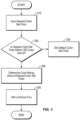
- Fig. 3 illustrates a method of mixing the light output from multiple LEDs 130 of different colors to produce a desired color set point.
- the method of Fig. 3 may be performed by the controller within the LED lighting module 110 and be employed during operation of the lighting module 110. In additional embodiments, the method may be performed by a controller within the module group controller 90, or other location which controls the LEDs 130 of the LED lighting module 110.
- a desired color set point on the CIE 1931 chromaticity diagram (x d , y d ) for the LED lighting module 110 is input.
- step 340 which one or more color mixing zones defined by the plurality of different color LEDs 130 of the LED lighting module 110 within which the desired color set point lies is determined.
- the method for determining the one or more color mixing zones in accordance with step 340 according to one embodiment will be described in more detail with reference to Figs. 4 - 9 .
- a CIE 1931 chromaticity diagram is illustrated with the three primaries (Red, Green, and Blue) forming the triangle.
- the controller creates ratio-metric mix of the primaries for the desired color point. This point may be referred to as D RGB .
- Fig. 5 the CIE 1931 chromaticity diagram of Fig. 2 including the two additional white LEDs (cool white and warm white) is illustrated.
- the controller determines the intersect point from the desired color point (D RGB ) to the gamut formed by the two whites (WW line). In an embodiment, the shortest distance from D RGB to the WW line is used by the controller to determine the intersect point.
- the controller may bias the intersect point by a predetermined amount (e.g., 10%) towards the warm white than the shortest distance to improve the CRI of the resulting mix.
- the controller biases the intersect point to ensure that it does not coincide with one of the white points. This ensures that both white LEDs are on at all times, thereby increasing the overall efficiency and CRI of the color mixing system.
- a ratio-metric mix of primaries (RGB) for the intersection point with the while line is created by the controller.
- RGB ratio-metric mix of primaries
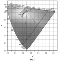
- the processor then subtracts W RGB from D RGB until one of the primaries of D RGB goes to zero. As shown in Fig. 7 , this "pushes" the color point away from W RGB until one of the colored LEDs is removed (Green in this instance). The resulting point may be referred to as Sat-D RGB .
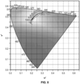
- the processor creates a mix of the warm white and cool white LEDs to produce a metameric equivalent of the color point W RGB as show in Fig. 8 . This color point may be referred to as Www.
- the controller adds the same proportion of Www that was removed previously (as shown in Fig. 7 ) to the D RGB color mix. As illustrated in Fig. 9 , this "pulls" the color point back toward W RGB . The resulting color point is a metameric equivalent of the D RGB , with the white mix substituting for one of the colored LEDs (Green in this instance).
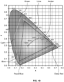
- the controller may substitute the white mix for any of the colored LEDs based on the desired color mix. For instance, as illustrated in Fig. 10 , the controller may drive the LEDs to obtain a lime color or an amber color by driving the royal blue content to null and replacing it with the white mix or obtain a cyan color by driving the deep red content to null. In various embodiments, the controller may obtain the metameric equivalents for the same color (for example, creating a warmer white which makes food appear more appetizing or creating a brilliant white with increased royal blue content which may make objects appear brighter) and appropriately drive the LEDs based on the desired needs.
- the luminous flux ratios of each of the LEDs 130 in the LED lighting module 110 are set according to the determined color mixing zone to produce the desired color set point. For example, if the desired set point is determined in step 340 to not contain any red color content, the luminous flux ratio of the red (R) LEDs 130 would be set to substantially zero, and the luminous flux ratios of each of the green (G), blue (B), cool white and warm white (W) LEDs 130 would be set appropriately to mix to produce the desired color set point on the chromaticity diagram.
- the LED lighting assembly described above may create various moods using the multiple solutions generated for each color point. For instance, it may be preferable to obtain a cooler orange during sunset, or to obtain a warmer orange during sunrise.
- the controller includes a user interface such as the ACP 40.
- the controller may be configured to receive an input indicating a desired color point (e.g. white) via the ACP 40.
- the controller may additionally be configured to receive an indication of a mood associated with the desired color point via the ACP 40. For instance, a warmer white may be desired when serving food to make the food appear more appetizing, while a brilliant white may be desired at boarding to give a brighter look to the cabin.
- the ACP 40 may be configured to receive an indication associated with an event (e.g., food, boarding, de-boarding, sunrise, sunset, etc.) and determine the desired color point based on the selected event.
- the LED lighting assembly upon receiving the desired color point and mood associated with the desired color point, drives the LEDs according to the color mixing scheme described above with reference to Figs. 4-9 . Accordingly, in an embodiment, when a brilliant white is selected via the user interface, the controller drives the various LEDs to obtain a white color with increased royal blue content, whereas when a warmer white is desired, the controller drives the various LEDs to obtain a metameric equivalent of the white color that includes increased deep red content. In an embodiment, the controller may have predetermined desired color points stored therein that are associated with specific events or time of day.
- the embodiment described with reference to Figs. 4 - 9 is not limited to using RGB primaries, and that any number of colored LEDs may be used to obtain the desired color gamut.
- the above color mixing method may be repeated for each additional color over three for as many colors as desired.
- the controller accounts for the changes in luminous flux of the LEDs based on the age of the respective LEDs and adjust the color mixing ratios appropriately.
- the primary LEDs consist of an Amber LED, a Cyan LED, a Magenta LED, and an Orange LED.
- additional color LEDs may be provided as part of the primary LEDs.
- one embodiment has been described above as having a cool white LED and an amber white LED.
- additional variations of white LEDs may be used instead without deviating from the scope of the disclosure.
- the ability to provide additional LEDs as part of the primary LEDs and driving the white LEDs to be constantly on results in a high resolution dimming (i.e., no perceivable steps) and CRI levels at approximately 99.
- the ability to use multiple LEDs provides the largest color gamut outputting any saturated color mix as well as high quality secondary colors such as cyan, pink, etc.
- the LED lighting assembly described is not limited and can apply to other applications as well.
- aircraft as used herein is to be understood as a proxy for any passenger vehicle or any illuminated area.
- LED or light-emitting diode is to be understood as a proxy for any illumination source that can be controllable in a manner similar to that described herein.
- illumination sources such as lasers etc. may be used in place of the LEDs described above.
- the system or systems may be implemented on any general purpose computer or computers and the components may be implemented as dedicated applications or in clientserver architectures, including a web-based architecture.
- Any of the computers may comprise a processor, a memory for storing program data and executing it, a permanent storage such as a disk drive, a communications port for handling communications with external devices, and user interface devices, including a display, keyboard, mouse, etc.
- these software modules may be stored as program instructions executable on the processor on media such as tape, CD-ROM, etc., where this media can be read by the computer, stored in the memory, and executed by the processor.
- the LED lighting assembly may employ various integrated circuit components, e.g., memory elements, processing elements, logic elements, and the like, which may carry out a variety of functions under the control of one or more microprocessors or other control devices.
- the elements of the described LED lighting assembly are implemented using software programming or software elements the LED lighting assembly may be implemented with any programming or scripting language such as C, C++, Java, assembler, or the like, with the various algorithms being implemented with any combination of data structures, objects, processes, routines or other programming elements.
- any number of conventional techniques for electronics configuration, signal processing and/or control, data processing and the like may be employed.
- the word mechanism is used broadly and is not limited to mechanical or physical embodiments, but can include software routines in conjunction with processors, etc.
Landscapes
- Engineering & Computer Science (AREA)
- Aviation & Aerospace Engineering (AREA)
- Mechanical Engineering (AREA)
- Circuit Arrangement For Electric Light Sources In General (AREA)
Claims (8)
- LED-Beleuchtungsbaugruppe (10), umfassend:
mindestens ein Beleuchtungsmodul (110), wobei jedes Beleuchtungsmodul umfasst:eine Vielzahl primärer LEDs, die jeweils eine jeweilige Farbe ausgeben;mindestens zwei zusätzliche LEDs, die jeweils eine weiße Farbe ausgeben;eine Steuerung (90), die dazu ausgelegt ist, jeweilige Ansteuersignale an jede der Vielzahl primärer LEDs und die beiden weißen LEDs des Beleuchtungsmoduls (110) zu liefern, wobei die jeweiligen Ansteuersignale einzeln relative Intensitätsausgaben der jeweiligen primären LEDs und der beiden weißen LEDs steuern,wobei die Steuerung (90) ferner dazu ausgelegt ist, einen gewünschten Farbpunkt anzuzeigen, indem die beiden weißen LEDs kontinuierlich angesteuert werden, während mindestens eine der Vielzahl primärer LEDs nicht angesteuert wird, und wobei das Anzeigen des gewünschten Farbpunkts umfasst:Bestimmen einer ratiometrischen Mischung der Ausgabe der primären LEDs, um dem gewünschten Farbpunkt zu entsprechen;Bestimmen einer ratiometrischen Mischung der Ausgabe der beiden weißen LEDs, um eine Weißmischung zu erhalten; und Bestimmen eines metameren Äquivalents des gewünschten Farbpunkts durch Ersetzen der Ausgabe von einer der primären LEDs mit der Weißmischung, wobeidie mindestens zwei zusätzlichen LEDs eine kaltweiße LED und eine warmweiße LED umfassen, und wobei die Steuerung ferner dazu ausgelegt ist, den Schnittpunkt vom gewünschten Farbpunkt (DRGB) zum Gamut zu bestimmen, der durch die kaltweiße Farbe und die warmweiße Farbe gebildet wird. - LED-Beleuchtungsbaugruppe nach Anspruch 1, wobei das Ersetzen von einer der primären LEDs mit der Weißmischung umfasst:Bestimmen einer ratiometrischen Mischung der Ausgabe der primären LEDs, um einem Farbpunkt der weißen LEDs zu entsprechen;Subtrahieren des abgestimmten Farbpunkts der weißen LEDs vom gewünschten Farbpunkt, bis sich die Ausgabe von einer der primären LEDs null nähert; undAddieren eines identischen Anteils der Weißmischung zu dem gewünschten Farbpunkt, der vom gewünschten Farbpunkt subtrahiert wurde.
- LED-Beleuchtungsbaugruppe nach Anspruch 1, wobei die LED-Beleuchtungsbaugruppe so konfiguriert ist, dass die beiden weißen LEDs immer eingeschaltet sind.
- LED-Beleuchtungsbaugruppe nach Anspruch 1, wobei die Steuerung ausgelegt ist zum:
Kalibrieren der LEDs, um Farbkonsistenz im Laufe der Zeit und über Temperaturänderungen hinweg beizubehalten. - Verfahren zum Steuern der Beleuchtung in einem Luftfahrzeug unter Verwendung einer LED-Beleuchtungsbaugruppe nach einem oder mehreren der Ansprüche 1 bis 4, wobei das Verfahren die folgenden Schritte umfasst:Empfangen einer gewünschten Farbauswahl über eine Benutzerschnittstelle an Bord des Luftfahrzeugs, wobei die gewünschte Farbauswahl eine Angabe eines Ereignisses beinhaltet, das mit einem gewünschten Farbpunkt assoziiert ist;Ansteuern der Vielzahl von LEDs mindestens eines Beleuchtungsmoduls (110) der LED-Beleuchtungsbaugruppe (10) über eine Steuerung (90), um eine Vielzahl metamerer Äquivalente des gewünschten Farbpunkts zu erzeugen, wobei die Steuerung dazu ausgelegt ist, für jedes des einen oder der mehreren Beleuchtungsmodule (110) Folgendes anzusteuern:eine Vielzahl primärer LEDs, die jeweils eine jeweilige Farbe ausgeben, undmindestens zwei zusätzliche LEDs, wobei eine eine kaltweiße Farbe ausgibt und eine eine warmweiße Farbe ausgibt; undAuswählen von einem der erzeugten Vielzahl metamerer Äquivalente des gewünschten Farbpunkts basierend auf dem angegeben Ereignis, das mit dem gewünschten Farbpunkt assoziiert ist, wobei das Erzeugen einer Vielzahl metamerer Äquivalente des gewünschten Farbpunkts umfasst:Bestimmen einer ratiometrischen Mischung der Ausgabe primärer LEDs, um dem gewünschten Farbpunkt zu entsprechen;Bestimmen einer ratiometrischen Mischung der Ausgabe der beiden weißen LEDs, um eine Weißmischung zu erhalten; und wobei das Erzeugen einer Vielzahl metamerer Äquivalente des gewünschten Farbpunkts ferner umfasst:Bestimmen eines metameren Äquivalents des gewünschten Farbpunkts durch Ersetzen der Ausgabe von einer der primären LEDs mit der Weißmischung, undBestimmen des Schnittpunkts vom gewünschten Farbpunkt (DRGB) zum Gamut, der durch die kaltweiße Farbe und die warmweiße Farbe gebildet wird.
- Verfahren nach Anspruch 5, wobei das Ersetzen der Ausgabe von einer der primären LEDs mit der Weißmischung umfasst:Bestimmen einer ratiometrischen Mischung der Ausgabe der primären LEDs, um einem Farbpunkt der weißen LEDs zu entsprechen;Subtrahieren des abgestimmten Farbpunkts der weißen LEDs vom gewünschten Farbpunkt, bis sich die Ausgabe von einer der primären LEDs null nähert; undAddieren eines identischen Anteils der Weißmischung zu dem gewünschten Farbpunkt, der vom gewünschten Farbpunkt subtrahiert wurde.
- Verfahren nach Anspruch 5, wobei die weißen LEDs immer eingeschaltet sind.
- Verfahren nach Anspruch 5, wobei die Steuerung ausgelegt ist zum:
Kalibrieren der LEDs, um Farbkonsistenz im Laufe der Zeit und über Temperaturänderungen hinweg beizubehalten.
Applications Claiming Priority (2)
| Application Number | Priority Date | Filing Date | Title |
|---|---|---|---|
| US15/338,930 US9868390B1 (en) | 2016-10-31 | 2016-10-31 | LED lighting assembly using a dynamic color mixing scheme |
| PCT/US2017/058490 WO2018081395A1 (en) | 2016-10-31 | 2017-10-26 | Led lighting assembly using a dynamic color mixing scheme |
Publications (2)
| Publication Number | Publication Date |
|---|---|
| EP3533294A1 EP3533294A1 (de) | 2019-09-04 |
| EP3533294B1 true EP3533294B1 (de) | 2024-11-27 |
Family
ID=60327387
Family Applications (1)
| Application Number | Title | Priority Date | Filing Date |
|---|---|---|---|
| EP17798042.2A Active EP3533294B1 (de) | 2016-10-31 | 2017-10-26 | Led-beleuchtungsanordnung mit einem dynamischen farbmischungsschema |
Country Status (4)
| Country | Link |
|---|---|
| US (1) | US9868390B1 (de) |
| EP (1) | EP3533294B1 (de) |
| CN (1) | CN109923941B (de) |
| WO (1) | WO2018081395A1 (de) |
Families Citing this family (3)
| Publication number | Priority date | Publication date | Assignee | Title |
|---|---|---|---|---|
| US10141533B2 (en) * | 2016-10-31 | 2018-11-27 | B/E Aerospace, Inc. | Quantum dot-based lighting system for an aircraft |
| CN109117492B (zh) * | 2018-06-15 | 2023-06-20 | 浙江阳光照明电器集团股份有限公司 | 用多个三峰同色异谱白光光谱来合成全光谱白光的方法 |
| US11490484B1 (en) | 2021-10-15 | 2022-11-01 | Aircraft Lighting International Inc. | Retrofit light-emitting diode lamp and circuit thereof |
Citations (1)
| Publication number | Priority date | Publication date | Assignee | Title |
|---|---|---|---|---|
| US20140375205A1 (en) * | 2013-06-22 | 2014-12-25 | Diehl Aerospace Gmbh | Arrangement having at least one metameric illuminating device, and passenger cabin |
Family Cites Families (14)
| Publication number | Priority date | Publication date | Assignee | Title |
|---|---|---|---|---|
| US6211626B1 (en) * | 1997-08-26 | 2001-04-03 | Color Kinetics, Incorporated | Illumination components |
| US7352339B2 (en) * | 1997-08-26 | 2008-04-01 | Philips Solid-State Lighting Solutions | Diffuse illumination systems and methods |
| TWI240241B (en) * | 2000-05-04 | 2005-09-21 | Koninkl Philips Electronics Nv | Assembly of a display device and an illumination system |
| US6995355B2 (en) * | 2003-06-23 | 2006-02-07 | Advanced Optical Technologies, Llc | Optical integrating chamber lighting using multiple color sources |
| US7256557B2 (en) * | 2004-03-11 | 2007-08-14 | Avago Technologies General Ip(Singapore) Pte. Ltd. | System and method for producing white light using a combination of phosphor-converted white LEDs and non-phosphor-converted color LEDs |
| US7821194B2 (en) * | 2006-04-18 | 2010-10-26 | Cree, Inc. | Solid state lighting devices including light mixtures |
| US8240875B2 (en) * | 2008-06-25 | 2012-08-14 | Cree, Inc. | Solid state linear array modules for general illumination |
| EP2329186B1 (de) * | 2008-09-24 | 2018-02-21 | B/E Aerospace Inc. | Flugzeug-led-scheinwerfersystem und steuerungsverfahren dafür |
| WO2011106661A1 (en) * | 2010-02-25 | 2011-09-01 | B/E Aerospace, Inc. | Calibration method for led lighting systems |
| CN102458019B (zh) * | 2010-10-26 | 2014-01-22 | 财团法人工业技术研究院 | 光色调制方法及发光二极管光源模块 |
| US8564205B2 (en) * | 2011-05-23 | 2013-10-22 | General Electric Company | Configurable vehicle solid state lighting |
| US8669722B2 (en) * | 2011-08-12 | 2014-03-11 | Tsmc Solid State Lighting Ltd. | Color temperature adjustment for LED lamps using switches |
| US8823285B2 (en) * | 2011-12-12 | 2014-09-02 | Cree, Inc. | Lighting devices including boost converters to control chromaticity and/or brightness and related methods |
| JP6581500B2 (ja) * | 2012-03-19 | 2019-09-25 | シグニファイ ホールディング ビー ヴィ | マルチチャネル白色光照明源のための装置、システム、及び方法 |
-
2016
- 2016-10-31 US US15/338,930 patent/US9868390B1/en active Active
-
2017
- 2017-10-26 EP EP17798042.2A patent/EP3533294B1/de active Active
- 2017-10-26 CN CN201780067354.XA patent/CN109923941B/zh active Active
- 2017-10-26 WO PCT/US2017/058490 patent/WO2018081395A1/en not_active Ceased
Patent Citations (1)
| Publication number | Priority date | Publication date | Assignee | Title |
|---|---|---|---|---|
| US20140375205A1 (en) * | 2013-06-22 | 2014-12-25 | Diehl Aerospace Gmbh | Arrangement having at least one metameric illuminating device, and passenger cabin |
Also Published As
| Publication number | Publication date |
|---|---|
| WO2018081395A1 (en) | 2018-05-03 |
| EP3533294A1 (de) | 2019-09-04 |
| CN109923941A (zh) | 2019-06-21 |
| US9868390B1 (en) | 2018-01-16 |
| CN109923941B (zh) | 2021-11-16 |
Similar Documents
| Publication | Publication Date | Title |
|---|---|---|
| US7204622B2 (en) | Methods and systems for illuminating environments | |
| US9227564B2 (en) | LED strip lighting device for a cabin of a passenger aircraft | |
| US9456478B2 (en) | System and method for controlling LED segments to provide lighting effects | |
| EP3533294B1 (de) | Led-beleuchtungsanordnung mit einem dynamischen farbmischungsschema | |
| WO2012033750A1 (en) | Led-based light source having decorative and illumination functions | |
| US10141533B2 (en) | Quantum dot-based lighting system for an aircraft | |
| EP4283602A1 (de) | Anzeigesystem mit aktivierter biorhythmusbeleuchtung, verfahren und vorrichtung | |
| US9185765B2 (en) | Arrangement having at least one metameric illuminating device, and passenger cabin | |
| US12396077B2 (en) | Illuminant device for emitting light of a continuously adjustable colour, in particular for individualizing and/or illuminating an interior space | |
| EP2732677B1 (de) | Steuerung für lichtemittierende vorrichtungen | |
| CN115366788B (zh) | 车辆内饰灯的控制方法、车辆及计算机存储介质 | |
| JP6277482B2 (ja) | Led照明器具 | |
| US20180359831A1 (en) | Led light, and method for influencing the spectral distribution of the led light | |
| US12382564B2 (en) | System and method for a circadian spectral weighting mode | |
| EP4125307A2 (de) | Systeme und verfahren für verbesserte beleuchtung | |
| US12349250B2 (en) | Night vision imaging system (NVIS) compatible lighting with an adjustable melanopic photopic ratio | |
| JP2025019667A (ja) | 照明制御システム | |
| GB2551384A (en) | LED lighting system for aircraft |
Legal Events
| Date | Code | Title | Description |
|---|---|---|---|
| STAA | Information on the status of an ep patent application or granted ep patent |
Free format text: STATUS: UNKNOWN |
|
| STAA | Information on the status of an ep patent application or granted ep patent |
Free format text: STATUS: THE INTERNATIONAL PUBLICATION HAS BEEN MADE |
|
| PUAI | Public reference made under article 153(3) epc to a published international application that has entered the european phase |
Free format text: ORIGINAL CODE: 0009012 |
|
| STAA | Information on the status of an ep patent application or granted ep patent |
Free format text: STATUS: REQUEST FOR EXAMINATION WAS MADE |
|
| 17P | Request for examination filed |
Effective date: 20190408 |
|
| AK | Designated contracting states |
Kind code of ref document: A1 Designated state(s): AL AT BE BG CH CY CZ DE DK EE ES FI FR GB GR HR HU IE IS IT LI LT LU LV MC MK MT NL NO PL PT RO RS SE SI SK SM TR |
|
| AX | Request for extension of the european patent |
Extension state: BA ME |
|
| DAV | Request for validation of the european patent (deleted) | ||
| DAX | Request for extension of the european patent (deleted) | ||
| STAA | Information on the status of an ep patent application or granted ep patent |
Free format text: STATUS: EXAMINATION IS IN PROGRESS |
|
| 17Q | First examination report despatched |
Effective date: 20211201 |
|
| P01 | Opt-out of the competence of the unified patent court (upc) registered |
Effective date: 20230608 |
|
| REG | Reference to a national code |
Ref country code: DE Ref legal event code: R079 Free format text: PREVIOUS MAIN CLASS: H05B0033080000 Ipc: H05B0045200000 Ref country code: DE Ref legal event code: R079 Ref document number: 602017086413 Country of ref document: DE Free format text: PREVIOUS MAIN CLASS: H05B0033080000 Ipc: H05B0045200000 |
|
| GRAP | Despatch of communication of intention to grant a patent |
Free format text: ORIGINAL CODE: EPIDOSNIGR1 |
|
| STAA | Information on the status of an ep patent application or granted ep patent |
Free format text: STATUS: GRANT OF PATENT IS INTENDED |
|
| INTG | Intention to grant announced |
Effective date: 20240910 |
|
| RIC1 | Information provided on ipc code assigned before grant |
Ipc: B64D 47/02 20060101ALI20240830BHEP Ipc: B64D 11/00 20060101ALI20240830BHEP Ipc: H05B 45/20 20200101AFI20240830BHEP |
|
| GRAS | Grant fee paid |
Free format text: ORIGINAL CODE: EPIDOSNIGR3 |
|
| GRAA | (expected) grant |
Free format text: ORIGINAL CODE: 0009210 |
|
| STAA | Information on the status of an ep patent application or granted ep patent |
Free format text: STATUS: THE PATENT HAS BEEN GRANTED |
|
| AK | Designated contracting states |
Kind code of ref document: B1 Designated state(s): AL AT BE BG CH CY CZ DE DK EE ES FI FR GB GR HR HU IE IS IT LI LT LU LV MC MK MT NL NO PL PT RO RS SE SI SK SM TR |
|
| REG | Reference to a national code |
Ref country code: GB Ref legal event code: FG4D |
|
| REG | Reference to a national code |
Ref country code: CH Ref legal event code: EP |
|
| REG | Reference to a national code |
Ref country code: DE Ref legal event code: R096 Ref document number: 602017086413 Country of ref document: DE |
|
| REG | Reference to a national code |
Ref country code: IE Ref legal event code: FG4D |
|
| REG | Reference to a national code |
Ref country code: LT Ref legal event code: MG9D |
|
| REG | Reference to a national code |
Ref country code: NL Ref legal event code: MP Effective date: 20241127 |
|
| PG25 | Lapsed in a contracting state [announced via postgrant information from national office to epo] |
Ref country code: PT Free format text: LAPSE BECAUSE OF FAILURE TO SUBMIT A TRANSLATION OF THE DESCRIPTION OR TO PAY THE FEE WITHIN THE PRESCRIBED TIME-LIMIT Effective date: 20250327 Ref country code: IS Free format text: LAPSE BECAUSE OF FAILURE TO SUBMIT A TRANSLATION OF THE DESCRIPTION OR TO PAY THE FEE WITHIN THE PRESCRIBED TIME-LIMIT Effective date: 20250327 Ref country code: HR Free format text: LAPSE BECAUSE OF FAILURE TO SUBMIT A TRANSLATION OF THE DESCRIPTION OR TO PAY THE FEE WITHIN THE PRESCRIBED TIME-LIMIT Effective date: 20241127 |
|
| PG25 | Lapsed in a contracting state [announced via postgrant information from national office to epo] |
Ref country code: FI Free format text: LAPSE BECAUSE OF FAILURE TO SUBMIT A TRANSLATION OF THE DESCRIPTION OR TO PAY THE FEE WITHIN THE PRESCRIBED TIME-LIMIT Effective date: 20241127 Ref country code: NL Free format text: LAPSE BECAUSE OF FAILURE TO SUBMIT A TRANSLATION OF THE DESCRIPTION OR TO PAY THE FEE WITHIN THE PRESCRIBED TIME-LIMIT Effective date: 20241127 |
|
| REG | Reference to a national code |
Ref country code: AT Ref legal event code: MK05 Ref document number: 1747020 Country of ref document: AT Kind code of ref document: T Effective date: 20241127 |
|
| PG25 | Lapsed in a contracting state [announced via postgrant information from national office to epo] |
Ref country code: BG Free format text: LAPSE BECAUSE OF FAILURE TO SUBMIT A TRANSLATION OF THE DESCRIPTION OR TO PAY THE FEE WITHIN THE PRESCRIBED TIME-LIMIT Effective date: 20241127 |
|
| PG25 | Lapsed in a contracting state [announced via postgrant information from national office to epo] |
Ref country code: ES Free format text: LAPSE BECAUSE OF FAILURE TO SUBMIT A TRANSLATION OF THE DESCRIPTION OR TO PAY THE FEE WITHIN THE PRESCRIBED TIME-LIMIT Effective date: 20241127 |
|
| PG25 | Lapsed in a contracting state [announced via postgrant information from national office to epo] |
Ref country code: NO Free format text: LAPSE BECAUSE OF FAILURE TO SUBMIT A TRANSLATION OF THE DESCRIPTION OR TO PAY THE FEE WITHIN THE PRESCRIBED TIME-LIMIT Effective date: 20250227 |
|
| PG25 | Lapsed in a contracting state [announced via postgrant information from national office to epo] |
Ref country code: LV Free format text: LAPSE BECAUSE OF FAILURE TO SUBMIT A TRANSLATION OF THE DESCRIPTION OR TO PAY THE FEE WITHIN THE PRESCRIBED TIME-LIMIT Effective date: 20241127 Ref country code: GR Free format text: LAPSE BECAUSE OF FAILURE TO SUBMIT A TRANSLATION OF THE DESCRIPTION OR TO PAY THE FEE WITHIN THE PRESCRIBED TIME-LIMIT Effective date: 20250228 Ref country code: AT Free format text: LAPSE BECAUSE OF FAILURE TO SUBMIT A TRANSLATION OF THE DESCRIPTION OR TO PAY THE FEE WITHIN THE PRESCRIBED TIME-LIMIT Effective date: 20241127 |
|
| PG25 | Lapsed in a contracting state [announced via postgrant information from national office to epo] |
Ref country code: PL Free format text: LAPSE BECAUSE OF FAILURE TO SUBMIT A TRANSLATION OF THE DESCRIPTION OR TO PAY THE FEE WITHIN THE PRESCRIBED TIME-LIMIT Effective date: 20241127 |
|
| PG25 | Lapsed in a contracting state [announced via postgrant information from national office to epo] |
Ref country code: RS Free format text: LAPSE BECAUSE OF FAILURE TO SUBMIT A TRANSLATION OF THE DESCRIPTION OR TO PAY THE FEE WITHIN THE PRESCRIBED TIME-LIMIT Effective date: 20250227 |
|
| PG25 | Lapsed in a contracting state [announced via postgrant information from national office to epo] |
Ref country code: SM Free format text: LAPSE BECAUSE OF FAILURE TO SUBMIT A TRANSLATION OF THE DESCRIPTION OR TO PAY THE FEE WITHIN THE PRESCRIBED TIME-LIMIT Effective date: 20241127 |
|
| PG25 | Lapsed in a contracting state [announced via postgrant information from national office to epo] |
Ref country code: DK Free format text: LAPSE BECAUSE OF FAILURE TO SUBMIT A TRANSLATION OF THE DESCRIPTION OR TO PAY THE FEE WITHIN THE PRESCRIBED TIME-LIMIT Effective date: 20241127 |
|
| PG25 | Lapsed in a contracting state [announced via postgrant information from national office to epo] |
Ref country code: EE Free format text: LAPSE BECAUSE OF FAILURE TO SUBMIT A TRANSLATION OF THE DESCRIPTION OR TO PAY THE FEE WITHIN THE PRESCRIBED TIME-LIMIT Effective date: 20241127 |
|
| PG25 | Lapsed in a contracting state [announced via postgrant information from national office to epo] |
Ref country code: RO Free format text: LAPSE BECAUSE OF FAILURE TO SUBMIT A TRANSLATION OF THE DESCRIPTION OR TO PAY THE FEE WITHIN THE PRESCRIBED TIME-LIMIT Effective date: 20241127 |
|
| PG25 | Lapsed in a contracting state [announced via postgrant information from national office to epo] |
Ref country code: SK Free format text: LAPSE BECAUSE OF FAILURE TO SUBMIT A TRANSLATION OF THE DESCRIPTION OR TO PAY THE FEE WITHIN THE PRESCRIBED TIME-LIMIT Effective date: 20241127 |
|
| PG25 | Lapsed in a contracting state [announced via postgrant information from national office to epo] |
Ref country code: CZ Free format text: LAPSE BECAUSE OF FAILURE TO SUBMIT A TRANSLATION OF THE DESCRIPTION OR TO PAY THE FEE WITHIN THE PRESCRIBED TIME-LIMIT Effective date: 20241127 |
|
| PG25 | Lapsed in a contracting state [announced via postgrant information from national office to epo] |
Ref country code: IT Free format text: LAPSE BECAUSE OF FAILURE TO SUBMIT A TRANSLATION OF THE DESCRIPTION OR TO PAY THE FEE WITHIN THE PRESCRIBED TIME-LIMIT Effective date: 20241127 |
|
| REG | Reference to a national code |
Ref country code: DE Ref legal event code: R097 Ref document number: 602017086413 Country of ref document: DE |
|
| PG25 | Lapsed in a contracting state [announced via postgrant information from national office to epo] |
Ref country code: SE Free format text: LAPSE BECAUSE OF FAILURE TO SUBMIT A TRANSLATION OF THE DESCRIPTION OR TO PAY THE FEE WITHIN THE PRESCRIBED TIME-LIMIT Effective date: 20241127 |
|
| PLBE | No opposition filed within time limit |
Free format text: ORIGINAL CODE: 0009261 |
|
| STAA | Information on the status of an ep patent application or granted ep patent |
Free format text: STATUS: NO OPPOSITION FILED WITHIN TIME LIMIT |
|
| PGFP | Annual fee paid to national office [announced via postgrant information from national office to epo] |
Ref country code: GB Payment date: 20250923 Year of fee payment: 9 |
|
| PGFP | Annual fee paid to national office [announced via postgrant information from national office to epo] |
Ref country code: FR Payment date: 20250924 Year of fee payment: 9 |
|
| 26N | No opposition filed |
Effective date: 20250828 |
|
| PGFP | Annual fee paid to national office [announced via postgrant information from national office to epo] |
Ref country code: DE Payment date: 20250923 Year of fee payment: 9 |