EP3532794B1 - Geräuschdämpfungsvorrichtung - Google Patents
Geräuschdämpfungsvorrichtung Download PDFInfo
- Publication number
- EP3532794B1 EP3532794B1 EP17784672.2A EP17784672A EP3532794B1 EP 3532794 B1 EP3532794 B1 EP 3532794B1 EP 17784672 A EP17784672 A EP 17784672A EP 3532794 B1 EP3532794 B1 EP 3532794B1
- Authority
- EP
- European Patent Office
- Prior art keywords
- barrel
- mortar
- extension portion
- range
- barrel extension
- Prior art date
- Legal status (The legal status is an assumption and is not a legal conclusion. Google has not performed a legal analysis and makes no representation as to the accuracy of the status listed.)
- Active
Links
Images

Classifications
-
- F—MECHANICAL ENGINEERING; LIGHTING; HEATING; WEAPONS; BLASTING
- F41—WEAPONS
- F41A—FUNCTIONAL FEATURES OR DETAILS COMMON TO BOTH SMALLARMS AND ORDNANCE, e.g. CANNONS; MOUNTINGS FOR SMALLARMS OR ORDNANCE
- F41A21/00—Barrels; Gun tubes; Muzzle attachments; Barrel mounting means
- F41A21/30—Silencers
-
- F—MECHANICAL ENGINEERING; LIGHTING; HEATING; WEAPONS; BLASTING
- F41—WEAPONS
- F41A—FUNCTIONAL FEATURES OR DETAILS COMMON TO BOTH SMALLARMS AND ORDNANCE, e.g. CANNONS; MOUNTINGS FOR SMALLARMS OR ORDNANCE
- F41A21/00—Barrels; Gun tubes; Muzzle attachments; Barrel mounting means
- F41A21/32—Muzzle attachments or glands
- F41A21/325—Mountings for muzzle attachments
-
- F—MECHANICAL ENGINEERING; LIGHTING; HEATING; WEAPONS; BLASTING
- F41—WEAPONS
- F41A—FUNCTIONAL FEATURES OR DETAILS COMMON TO BOTH SMALLARMS AND ORDNANCE, e.g. CANNONS; MOUNTINGS FOR SMALLARMS OR ORDNANCE
- F41A21/00—Barrels; Gun tubes; Muzzle attachments; Barrel mounting means
- F41A21/32—Muzzle attachments or glands
- F41A21/34—Flash dampers
-
- F—MECHANICAL ENGINEERING; LIGHTING; HEATING; WEAPONS; BLASTING
- F41—WEAPONS
- F41A—FUNCTIONAL FEATURES OR DETAILS COMMON TO BOTH SMALLARMS AND ORDNANCE, e.g. CANNONS; MOUNTINGS FOR SMALLARMS OR ORDNANCE
- F41A21/00—Barrels; Gun tubes; Muzzle attachments; Barrel mounting means
- F41A21/32—Muzzle attachments or glands
- F41A21/36—Muzzle attachments or glands for recoil reduction ; Stabilisators; Compensators, e.g. for muzzle climb prevention
Definitions
- This invention relates to a noise attenuation device and in particular a device which provides an increased performance in the range of a mortar system.
- Blast attenuation devices such as muzzle brakes are well known in the art. They typically provide a means of allowing the rapid dispersion of the hot gases. Further features on these device is that they use apertures, such as slits or holes to allow the gases to disperse radially outwardly, to reduce the recoil of the barrel and attached ordnance.
- a noise attenuation device for mortar is for instance known from EP1 956 335 A2 .
- the invention is a noise attenuation device according to claim 1.
- the tapered portion may alternatively be, cupola, parabola, flared portion, to allow the controlled dispersion of the gases produced as the munition leaves the barrel.
- the height of the tapered portion is in the range of from 5cm to 30cm, more preferably in the range of from 10cm to 20 cm more preferably the height of the frustroconical portion is in the range of from 10 cm to 20 cm, most preferably 13.34cm.
- the tapered portion may have sides which may be substantially straight, parabolic, curved, trumpet shaped sides, in a highly preferred arrangement the tapered portion has substantially straight sides.
- the frustroconical portion has a base.
- the plane of the base may be substantially perpendicular to the plane of the barrel extension portion or it may be an elliptical/parabolic conic section, or slant cut.
- the base may have any shaped cross section, such as for example elliptical, circular, square, highly preferably a right angled frustrated cone with a substantially circular base.
- the tapered portion comprises an inner surface and an outer surface, the inner surface may comprise a textured surface, such as for example concave convex portions, such as for example ridges, grooves, voids, such as to alter the flow of the combustion gases.
- the inner surface of the tapered portion may comprise a coating or layer, to alter the friction of the surface, such as paints, polymers etc.
- the barrel extension portion is a tube with an internal diameter (bore) substantially the same as the internal diameter(bore) as the munition barrel to which it is attached, such that the munition to be launched retains substantially the same gas tight seal in the barrel extension portion.
- the barrel extension portion has a length in the range of from 10 cm to 60cm, more preferably 30cm to 60cm, yet more preferably 30 cm to 50cm, more preferably 45cm.
- the barrel extension portion has a length which is greater than the height of the frustroconical cone, more preferably the length is in the range of from 2 to 4 times the height of the frustroconical cone.
- the device may be manufactured from any suitable material, such as a metal, polymer, composite, preferably a metal, preferably steel.
- a metal such as a metal, polymer, composite, preferably a metal, preferably steel.
- the barrel extension portion and taper are selected from the same material.
- the barrel extension portion when deployed on the munition barrel, provides a temporary increase in overall barrel length, thereby increasing the time that the munition experiences the impulse from the hot expanding gases from the burning propellant. This may allow a reduction in the mass of propellant required to achieve the same range usually achievable with the munition's normal propellant mass. The reduction of propellant required to achieve the current maximum range, reduces the blast pressure.
- the combination of reduced propellant mass munition and a device according to the invention comprising a tapered portion may provide a reduction in noise to operators located around the weapon.
- Ii has been shown that a device when attached to a munition barrel allows a reduced mass propellant munition to be launched and to achieve substantially the same range.
- the connector must provide a gas tight seal between the device and the munition barrel.
- the connector and munition barrel may comprise co-operatively engaging surfaces, such as threads, collets, locking rings.
- the tapered portion may be reversibly attached to the barrel extension portion, such that the device may be more conveniently stored.
- a munition system comprising a munition barrel, a munition capable of being launched via said barrel, and a noise attenuation device as defined herein, said attenuation device attached by a connector to said munition barrel, wherein the munition has a reduced mass of propellant.
- the reduction may be at least 1%wt, preferably at least 10%wt, more preferably in the range of from 5 to 20%wt.
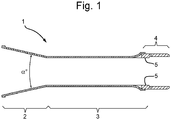
- a noise attenuation device 1 the device comprises a barrel extension portion 3.
- a tapered portion 2 which is preferably in the form of a frustrated cone.
- the tapered portion 2 is tapered such that the sides expand outwardly as a function of distance from the barrel extension portion.
- the cone angle ⁇ ° is 25°.
- the connector 4 allows the barrel extension portion 3 to be connected to an existing munition barrel, such as a mortar barrel.
- the inner surface (bore) 5 of the barrel extension portion 3, should be substantially the same bore as the munition barrel to ensuring a gas tight seal with a munition progressing up the barrel extension portion.
- the mortar launcher 10 comprises a barrel portion 15, which is supported by a base plate 16, which may be sunk into the ground.
- the mortar launcher 10, is further supported by a bi-pod 17, to allow the mortar launcher 10 to be arranged at a specific elevation.
- a noise reduction device 11 At the open end of the mortar barrel 15, is located a noise reduction device 11.
- the noise reduction device 11 comprises a barrel extension portion 13.
- a tapered portion 12 At a first end of the barrel extension portion 13 is a tapered portion 12, which is preferably in the form of a frustrated cone.
- the connector 14 reversibly connects the noise reduction device 11 to the open end of the barrel 15.
- a mortar bomb 18 is then deposited down the elongate barrel portion 12 and barrel 15. It is essential that the elongate barrel portion 12 and barrel 15 are of substantially the same bore, (same inner diameters) such that the mortar bomb 18 forms a gas tight seal via the obturator 19, with the inner wall of the barrel 15 and elongate barrel portion 12.
Landscapes
- Engineering & Computer Science (AREA)
- General Engineering & Computer Science (AREA)
- Percussive Tools And Related Accessories (AREA)
- Filling Or Discharging Of Gas Storage Vessels (AREA)
Claims (10)
- Schalldämpfvorrichtung (1), die zur Verwendung an einem Mörserlauf geeignet ist, wobei die Vorrichtung umfasst:
einen Laufverlängerungsabschnitt (3), wobei der Laufverlängerungsabschnitt eine Länge im Bereich von 10 cm bis 60 cm aufweist, wobei der Laufverlängerungsabschnitt ein Rohr mit einem Innendurchmesser ist, der im Wesentlichen gleich wie der Innendurchmesser des Mörserlaufs ist, derart dass ein abzufeuernder Mörser im Wesentlichen die gleiche gasdichte Abdichtung im Laufverlängerungsabschnitt bewahrt, wobei an einem ersten Ende des Laufverlängerungsabschnitts ein kegeliger Abschnitt (2), der vom Laufverlängerungsabschnitt kegelförmig auseinanderläuft, wobei der kegelige Abschnitt kegelstumpfförmig ist und einen Kegelwinkel im Bereich von 22° bis 28° aufweist, und an einem zweiten Ende des Laufverlängerungsabschnitts ein Verbinder zum Befestigen der Vorrichtung am Mörserlauf vorhanden ist. - Vorrichtung nach Anspruch 1, wobei der kegelstumpfförmige Abschnitt einen Kegelwinkel von im Wesentlichen 25° aufweist.
- Vorrichtung nach einem der vorhergehenden Ansprüche, wobei der Laufverlängerungsabschnitt eine Länge im Bereich von 30 cm bis 60 cm aufweist.
- Vorrichtung nach einem der vorhergehenden Ansprüche, wobei der Laufverlängerungsabschnitt eine Länge im Bereich von 45 cm aufweist.
- Vorrichtung nach einem Ansprüche 2 bis 4, wobei die Höhe des kegelstumpfförmigen Abschnitts im Bereich von 10 cm bis 17 cm liegt.
- Vorrichtung nach einem der vorhergehenden Ansprüche, wobei die Vorrichtung, wenn am Mörserlauf angebracht, ermöglicht, dass ein Mörser mit Treibladung reduzierter Masse abgefeuert wird und im Wesentlichen die gleiche Reichweite erreicht.
- Vorrichtung nach einem der vorhergehenden Ansprüche, wobei der Verbinder und der Mörserlauf zusammenwirkend in Eingriff stehende Flächen umfassen.
- Vorrichtung nach einem der vorhergehenden Ansprüche, wobei der kegelige Abschnitt reversibel am Laufverlängerungsabschnitt angebracht ist.
- Mörsersystem, umfassend einen Mörserlauf, einen Mörser, der durch den Lauf abgefeuert werden kann, und eine Schalldämpfvorrichtung nach einem der vorhergehenden Ansprüche, wobei die Schalldämpfvorrichtung durch einen Verbinder am Mörserlauf angebracht ist, wobei der Mörser eine reduzierte Masse Treibladung aufweist.
- System nach Anspruch 9, wobei die Reduktion der Treibladung im Bereich von 5 bis 20 Gew% liegt.
Applications Claiming Priority (3)
| Application Number | Priority Date | Filing Date | Title |
|---|---|---|---|
| GB1618226.3A GB2555579B (en) | 2016-10-28 | 2016-10-28 | Noise attenuation device |
| EP16275159.8A EP3315892A1 (de) | 2016-10-28 | 2016-10-28 | Geräuschdämpfer |
| PCT/GB2017/053013 WO2018078320A1 (en) | 2016-10-28 | 2017-10-05 | Noise attenuation device |
Publications (2)
| Publication Number | Publication Date |
|---|---|
| EP3532794A1 EP3532794A1 (de) | 2019-09-04 |
| EP3532794B1 true EP3532794B1 (de) | 2020-12-09 |
Family
ID=60117702
Family Applications (1)
| Application Number | Title | Priority Date | Filing Date |
|---|---|---|---|
| EP17784672.2A Active EP3532794B1 (de) | 2016-10-28 | 2017-10-05 | Geräuschdämpfungsvorrichtung |
Country Status (4)
| Country | Link |
|---|---|
| US (1) | US10670363B2 (de) |
| EP (1) | EP3532794B1 (de) |
| LT (1) | LT3532794T (de) |
| WO (1) | WO2018078320A1 (de) |
Families Citing this family (2)
| Publication number | Priority date | Publication date | Assignee | Title |
|---|---|---|---|---|
| EP3532794B1 (de) | 2016-10-28 | 2020-12-09 | BAE Systems PLC | Geräuschdämpfungsvorrichtung |
| US11609060B1 (en) * | 2020-08-20 | 2023-03-21 | The United States Of America As Represented By The Secretary Of The Army | Attenuating blast cone |
Family Cites Families (18)
| Publication number | Priority date | Publication date | Assignee | Title |
|---|---|---|---|---|
| FR593782A (fr) | 1925-02-23 | 1925-08-31 | Perfectionnements aux canons légers dits de tranchée ou d'accompagnement d'infanterie | |
| GB586749A (en) * | 1941-12-05 | 1947-03-31 | Charles Dennistoun Burney | Improvements in or relating to ordnance and small arms |
| DE1553895A1 (de) | 1967-04-01 | 1972-04-13 | Tampella Oy Ab | Rohrende bzw. Muendungsaufsatz an Rohren fuer drallose Geschosse |
| CA1201616A (en) * | 1984-05-15 | 1986-03-11 | David H. Gladstone | Carbon fibre gun barrel |
| WO1993008439A1 (en) | 1991-10-17 | 1993-04-29 | Vinghøgs Mek. Verksted As | Pressure reducer for a gun muzzle |
| US5429032A (en) * | 1994-08-10 | 1995-07-04 | The United States Of America As Represented By The Secretary Of The Army | Lightweight mortar and baseplate apparatus |
| US6059573A (en) * | 1998-03-20 | 2000-05-09 | Fats, Inc. | Mortar training device with functional simulated propelling charges |
| IL125989A (en) * | 1998-08-30 | 2004-07-25 | Moshe Eizenman | Apertured barrel extension for weapons for preventing raising of dust |
| US20060288854A1 (en) * | 2004-10-07 | 2006-12-28 | Mark Witherell | Superalloy mortar tube |
| US7735408B1 (en) * | 2004-10-14 | 2010-06-15 | The United States Of America As Represented By The Secretary Of The Army | Mortar tube with cooling fin |
| US7082823B1 (en) * | 2005-01-14 | 2006-08-01 | Honeywell International, Inc. | Digital signal processing back biased hall effect muzzle velocity measurement system |
| US7421934B1 (en) * | 2005-09-01 | 2008-09-09 | The United States Of America As Represented By The Secretary Of The Army | Mortar tube for training |
| US7963202B1 (en) * | 2005-09-21 | 2011-06-21 | The United States Of America As Represented By The Secretary Of The Army | Superalloy mortar tube |
| US7798046B2 (en) | 2006-03-21 | 2010-09-21 | Honeywell International Inc. | Mortar blast attenuator diffuser |
| US7595633B2 (en) * | 2007-02-08 | 2009-09-29 | Honeywell International Inc. | Velocity measurement using magnetoresistive sensors |
| FR2989773A1 (fr) | 2012-04-24 | 2013-10-25 | Tda Armements Sas | Attenuateur de bruit pour mortier |
| US9863732B2 (en) * | 2013-08-28 | 2018-01-09 | Proof Research, Inc. | Lightweight composite mortar tube |
| EP3532794B1 (de) | 2016-10-28 | 2020-12-09 | BAE Systems PLC | Geräuschdämpfungsvorrichtung |
-
2017
- 2017-10-05 EP EP17784672.2A patent/EP3532794B1/de active Active
- 2017-10-05 US US16/345,567 patent/US10670363B2/en active Active
- 2017-10-05 WO PCT/GB2017/053013 patent/WO2018078320A1/en not_active Ceased
- 2017-10-05 LT LTEP17784672.2T patent/LT3532794T/lt unknown
Also Published As
| Publication number | Publication date |
|---|---|
| WO2018078320A1 (en) | 2018-05-03 |
| EP3532794A1 (de) | 2019-09-04 |
| US20190264997A1 (en) | 2019-08-29 |
| US10670363B2 (en) | 2020-06-02 |
| LT3532794T (lt) | 2021-01-11 |
Similar Documents
| Publication | Publication Date | Title |
|---|---|---|
| US9903678B2 (en) | Method of manufacturing a diffuser muzzle brake | |
| US9423198B1 (en) | Flash hider with gas flow control modules and associated methods | |
| US8166861B2 (en) | Shock reduction muzzle brake | |
| US9476662B2 (en) | Silencer for a long gun | |
| US8418803B2 (en) | Flash suppressor | |
| US10274278B2 (en) | Firearm attachment | |
| US20160018178A1 (en) | Silencer for a firearm | |
| US10234229B2 (en) | Muzzle end accessory mount for a firearm | |
| US11428490B2 (en) | Inaudible frequency suppressor | |
| US20190041155A1 (en) | Muzzle Device | |
| EP3171119B1 (de) | Schusswaffenschalldämpfer und verfahren zum betrieb | |
| US9976830B2 (en) | Firearm barrel including a gas pressure relief chamber | |
| US9417022B2 (en) | Combination flash hider and muzzle brake | |
| EP3532794B1 (de) | Geräuschdämpfungsvorrichtung | |
| US9163892B1 (en) | Muzzle break with supersonic nozzle | |
| EP2643652B1 (de) | Patroniertes projektil | |
| EP3382318A1 (de) | Schalldämpfer für eine schrottflinte | |
| CN101970972B (zh) | 用来支撑进入武器炮筒中的炮弹的装置、支撑部件和方法 | |
| EP3315892A1 (de) | Geräuschdämpfer | |
| US8550002B2 (en) | Arrangement for supporting mortar shell into breech-loading weapon barrel | |
| GB2555579A (en) | Noise attenuation device | |
| RU2494333C1 (ru) | Быстросъемный глушитель | |
| US8322264B1 (en) | Controlled plastic venting for low-recoil gun systems | |
| US20180010874A1 (en) | Firearm flash hider | |
| US20260098699A1 (en) | Apparatus and methods for a muzzle brake |
Legal Events
| Date | Code | Title | Description |
|---|---|---|---|
| STAA | Information on the status of an ep patent application or granted ep patent |
Free format text: STATUS: UNKNOWN |
|
| STAA | Information on the status of an ep patent application or granted ep patent |
Free format text: STATUS: THE INTERNATIONAL PUBLICATION HAS BEEN MADE |
|
| PUAI | Public reference made under article 153(3) epc to a published international application that has entered the european phase |
Free format text: ORIGINAL CODE: 0009012 |
|
| STAA | Information on the status of an ep patent application or granted ep patent |
Free format text: STATUS: REQUEST FOR EXAMINATION WAS MADE |
|
| 17P | Request for examination filed |
Effective date: 20190425 |
|
| AK | Designated contracting states |
Kind code of ref document: A1 Designated state(s): AL AT BE BG CH CY CZ DE DK EE ES FI FR GB GR HR HU IE IS IT LI LT LU LV MC MK MT NL NO PL PT RO RS SE SI SK SM TR |
|
| AX | Request for extension of the european patent |
Extension state: BA ME |
|
| DAV | Request for validation of the european patent (deleted) | ||
| DAX | Request for extension of the european patent (deleted) | ||
| GRAP | Despatch of communication of intention to grant a patent |
Free format text: ORIGINAL CODE: EPIDOSNIGR1 |
|
| STAA | Information on the status of an ep patent application or granted ep patent |
Free format text: STATUS: GRANT OF PATENT IS INTENDED |
|
| INTG | Intention to grant announced |
Effective date: 20200528 |
|
| GRAS | Grant fee paid |
Free format text: ORIGINAL CODE: EPIDOSNIGR3 |
|
| GRAA | (expected) grant |
Free format text: ORIGINAL CODE: 0009210 |
|
| STAA | Information on the status of an ep patent application or granted ep patent |
Free format text: STATUS: THE PATENT HAS BEEN GRANTED |
|
| AK | Designated contracting states |
Kind code of ref document: B1 Designated state(s): AL AT BE BG CH CY CZ DE DK EE ES FI FR GB GR HR HU IE IS IT LI LT LU LV MC MK MT NL NO PL PT RO RS SE SI SK SM TR |
|
| REG | Reference to a national code |
Ref country code: GB Ref legal event code: FG4D |
|
| REG | Reference to a national code |
Ref country code: AT Ref legal event code: REF Ref document number: 1343880 Country of ref document: AT Kind code of ref document: T Effective date: 20201215 Ref country code: CH Ref legal event code: EP |
|
| REG | Reference to a national code |
Ref country code: DE Ref legal event code: R096 Ref document number: 602017029346 Country of ref document: DE |
|
| REG | Reference to a national code |
Ref country code: IE Ref legal event code: FG4D |
|
| REG | Reference to a national code |
Ref country code: PT Ref legal event code: SC4A Ref document number: 3532794 Country of ref document: PT Date of ref document: 20210202 Kind code of ref document: T Free format text: AVAILABILITY OF NATIONAL TRANSLATION Effective date: 20210126 |
|
| REG | Reference to a national code |
Ref country code: NL Ref legal event code: FP |
|
| REG | Reference to a national code |
Ref country code: EE Ref legal event code: FG4A Ref document number: E020343 Country of ref document: EE Effective date: 20210105 |
|
| REG | Reference to a national code |
Ref country code: NO Ref legal event code: T2 Effective date: 20201209 |
|
| PG25 | Lapsed in a contracting state [announced via postgrant information from national office to epo] |
Ref country code: GR Free format text: LAPSE BECAUSE OF FAILURE TO SUBMIT A TRANSLATION OF THE DESCRIPTION OR TO PAY THE FEE WITHIN THE PRESCRIBED TIME-LIMIT Effective date: 20210310 Ref country code: RS Free format text: LAPSE BECAUSE OF FAILURE TO SUBMIT A TRANSLATION OF THE DESCRIPTION OR TO PAY THE FEE WITHIN THE PRESCRIBED TIME-LIMIT Effective date: 20201209 Ref country code: FI Free format text: LAPSE BECAUSE OF FAILURE TO SUBMIT A TRANSLATION OF THE DESCRIPTION OR TO PAY THE FEE WITHIN THE PRESCRIBED TIME-LIMIT Effective date: 20201209 |
|
| PG25 | Lapsed in a contracting state [announced via postgrant information from national office to epo] |
Ref country code: SE Free format text: LAPSE BECAUSE OF FAILURE TO SUBMIT A TRANSLATION OF THE DESCRIPTION OR TO PAY THE FEE WITHIN THE PRESCRIBED TIME-LIMIT Effective date: 20201209 Ref country code: BG Free format text: LAPSE BECAUSE OF FAILURE TO SUBMIT A TRANSLATION OF THE DESCRIPTION OR TO PAY THE FEE WITHIN THE PRESCRIBED TIME-LIMIT Effective date: 20210309 |
|
| PG25 | Lapsed in a contracting state [announced via postgrant information from national office to epo] |
Ref country code: HR Free format text: LAPSE BECAUSE OF FAILURE TO SUBMIT A TRANSLATION OF THE DESCRIPTION OR TO PAY THE FEE WITHIN THE PRESCRIBED TIME-LIMIT Effective date: 20201209 |
|
| PG25 | Lapsed in a contracting state [announced via postgrant information from national office to epo] |
Ref country code: SK Free format text: LAPSE BECAUSE OF FAILURE TO SUBMIT A TRANSLATION OF THE DESCRIPTION OR TO PAY THE FEE WITHIN THE PRESCRIBED TIME-LIMIT Effective date: 20201209 Ref country code: RO Free format text: LAPSE BECAUSE OF FAILURE TO SUBMIT A TRANSLATION OF THE DESCRIPTION OR TO PAY THE FEE WITHIN THE PRESCRIBED TIME-LIMIT Effective date: 20201209 Ref country code: SM Free format text: LAPSE BECAUSE OF FAILURE TO SUBMIT A TRANSLATION OF THE DESCRIPTION OR TO PAY THE FEE WITHIN THE PRESCRIBED TIME-LIMIT Effective date: 20201209 |
|
| PG25 | Lapsed in a contracting state [announced via postgrant information from national office to epo] |
Ref country code: PL Free format text: LAPSE BECAUSE OF FAILURE TO SUBMIT A TRANSLATION OF THE DESCRIPTION OR TO PAY THE FEE WITHIN THE PRESCRIBED TIME-LIMIT Effective date: 20201209 |
|
| REG | Reference to a national code |
Ref country code: DE Ref legal event code: R097 Ref document number: 602017029346 Country of ref document: DE |
|
| PG25 | Lapsed in a contracting state [announced via postgrant information from national office to epo] |
Ref country code: IS Free format text: LAPSE BECAUSE OF FAILURE TO SUBMIT A TRANSLATION OF THE DESCRIPTION OR TO PAY THE FEE WITHIN THE PRESCRIBED TIME-LIMIT Effective date: 20210409 |
|
| PLBE | No opposition filed within time limit |
Free format text: ORIGINAL CODE: 0009261 |
|
| STAA | Information on the status of an ep patent application or granted ep patent |
Free format text: STATUS: NO OPPOSITION FILED WITHIN TIME LIMIT |
|
| PG25 | Lapsed in a contracting state [announced via postgrant information from national office to epo] |
Ref country code: IT Free format text: LAPSE BECAUSE OF FAILURE TO SUBMIT A TRANSLATION OF THE DESCRIPTION OR TO PAY THE FEE WITHIN THE PRESCRIBED TIME-LIMIT Effective date: 20201209 Ref country code: AL Free format text: LAPSE BECAUSE OF FAILURE TO SUBMIT A TRANSLATION OF THE DESCRIPTION OR TO PAY THE FEE WITHIN THE PRESCRIBED TIME-LIMIT Effective date: 20201209 |
|
| 26N | No opposition filed |
Effective date: 20210910 |
|
| PG25 | Lapsed in a contracting state [announced via postgrant information from national office to epo] |
Ref country code: DK Free format text: LAPSE BECAUSE OF FAILURE TO SUBMIT A TRANSLATION OF THE DESCRIPTION OR TO PAY THE FEE WITHIN THE PRESCRIBED TIME-LIMIT Effective date: 20201209 Ref country code: SI Free format text: LAPSE BECAUSE OF FAILURE TO SUBMIT A TRANSLATION OF THE DESCRIPTION OR TO PAY THE FEE WITHIN THE PRESCRIBED TIME-LIMIT Effective date: 20201209 |
|
| PG25 | Lapsed in a contracting state [announced via postgrant information from national office to epo] |
Ref country code: ES Free format text: LAPSE BECAUSE OF FAILURE TO SUBMIT A TRANSLATION OF THE DESCRIPTION OR TO PAY THE FEE WITHIN THE PRESCRIBED TIME-LIMIT Effective date: 20201209 |
|
| REG | Reference to a national code |
Ref country code: CH Ref legal event code: PL |
|
| PG25 | Lapsed in a contracting state [announced via postgrant information from national office to epo] |
Ref country code: IS Free format text: LAPSE BECAUSE OF FAILURE TO SUBMIT A TRANSLATION OF THE DESCRIPTION OR TO PAY THE FEE WITHIN THE PRESCRIBED TIME-LIMIT Effective date: 20210409 |
|
| PG25 | Lapsed in a contracting state [announced via postgrant information from national office to epo] |
Ref country code: MC Free format text: LAPSE BECAUSE OF FAILURE TO SUBMIT A TRANSLATION OF THE DESCRIPTION OR TO PAY THE FEE WITHIN THE PRESCRIBED TIME-LIMIT Effective date: 20201209 |
|
| PG25 | Lapsed in a contracting state [announced via postgrant information from national office to epo] |
Ref country code: LI Free format text: LAPSE BECAUSE OF NON-PAYMENT OF DUE FEES Effective date: 20211031 Ref country code: CH Free format text: LAPSE BECAUSE OF NON-PAYMENT OF DUE FEES Effective date: 20211031 |
|
| REG | Reference to a national code |
Ref country code: AT Ref legal event code: UEP Ref document number: 1343880 Country of ref document: AT Kind code of ref document: T Effective date: 20201209 |
|
| PG25 | Lapsed in a contracting state [announced via postgrant information from national office to epo] |
Ref country code: IE Free format text: LAPSE BECAUSE OF NON-PAYMENT OF DUE FEES Effective date: 20211005 |
|
| PG25 | Lapsed in a contracting state [announced via postgrant information from national office to epo] |
Ref country code: CY Free format text: LAPSE BECAUSE OF FAILURE TO SUBMIT A TRANSLATION OF THE DESCRIPTION OR TO PAY THE FEE WITHIN THE PRESCRIBED TIME-LIMIT Effective date: 20201209 |
|
| PG25 | Lapsed in a contracting state [announced via postgrant information from national office to epo] |
Ref country code: HU Free format text: LAPSE BECAUSE OF FAILURE TO SUBMIT A TRANSLATION OF THE DESCRIPTION OR TO PAY THE FEE WITHIN THE PRESCRIBED TIME-LIMIT; INVALID AB INITIO Effective date: 20171005 |
|
| PG25 | Lapsed in a contracting state [announced via postgrant information from national office to epo] |
Ref country code: MK Free format text: LAPSE BECAUSE OF FAILURE TO SUBMIT A TRANSLATION OF THE DESCRIPTION OR TO PAY THE FEE WITHIN THE PRESCRIBED TIME-LIMIT Effective date: 20201209 |
|
| PG25 | Lapsed in a contracting state [announced via postgrant information from national office to epo] |
Ref country code: MT Free format text: LAPSE BECAUSE OF FAILURE TO SUBMIT A TRANSLATION OF THE DESCRIPTION OR TO PAY THE FEE WITHIN THE PRESCRIBED TIME-LIMIT Effective date: 20201209 |
|
| PGFP | Annual fee paid to national office [announced via postgrant information from national office to epo] |
Ref country code: PT Payment date: 20250926 Year of fee payment: 9 |
|
| PGFP | Annual fee paid to national office [announced via postgrant information from national office to epo] |
Ref country code: LT Payment date: 20250923 Year of fee payment: 9 |
|
| PGFP | Annual fee paid to national office [announced via postgrant information from national office to epo] |
Ref country code: NO Payment date: 20250925 Year of fee payment: 9 |
|
| PGFP | Annual fee paid to national office [announced via postgrant information from national office to epo] |
Ref country code: NL Payment date: 20250923 Year of fee payment: 9 Ref country code: LU Payment date: 20250923 Year of fee payment: 9 |
|
| PGFP | Annual fee paid to national office [announced via postgrant information from national office to epo] |
Ref country code: BE Payment date: 20250923 Year of fee payment: 9 Ref country code: GB Payment date: 20250923 Year of fee payment: 9 |
|
| PGFP | Annual fee paid to national office [announced via postgrant information from national office to epo] |
Ref country code: FR Payment date: 20250924 Year of fee payment: 9 |
|
| PGFP | Annual fee paid to national office [announced via postgrant information from national office to epo] |
Ref country code: EE Payment date: 20250927 Year of fee payment: 9 Ref country code: CZ Payment date: 20250926 Year of fee payment: 9 |
|
| PGFP | Annual fee paid to national office [announced via postgrant information from national office to epo] |
Ref country code: LV Payment date: 20250923 Year of fee payment: 9 |
|
| PG25 | Lapsed in a contracting state [announced via postgrant information from national office to epo] |
Ref country code: TR Free format text: LAPSE BECAUSE OF FAILURE TO SUBMIT A TRANSLATION OF THE DESCRIPTION OR TO PAY THE FEE WITHIN THE PRESCRIBED TIME-LIMIT Effective date: 20201209 |
|
| PGFP | Annual fee paid to national office [announced via postgrant information from national office to epo] |
Ref country code: DE Payment date: 20250923 Year of fee payment: 9 |
|
| PGFP | Annual fee paid to national office [announced via postgrant information from national office to epo] |
Ref country code: AT Payment date: 20250926 Year of fee payment: 9 |