EP3532702B1 - Schätzungsansatz zur verwendung mit einem virtuellen durchflussmesser - Google Patents
Schätzungsansatz zur verwendung mit einem virtuellen durchflussmesser Download PDFInfo
- Publication number
- EP3532702B1 EP3532702B1 EP17754901.1A EP17754901A EP3532702B1 EP 3532702 B1 EP3532702 B1 EP 3532702B1 EP 17754901 A EP17754901 A EP 17754901A EP 3532702 B1 EP3532702 B1 EP 3532702B1
- Authority
- EP
- European Patent Office
- Prior art keywords
- fluid
- pressure
- pressure loss
- flow meter
- gathering network
- Prior art date
- Legal status (The legal status is an assumption and is not a legal conclusion. Google has not performed a legal analysis and makes no representation as to the accuracy of the status listed.)
- Active
Links
Images

Classifications
-
- G—PHYSICS
- G01—MEASURING; TESTING
- G01F—MEASURING VOLUME, VOLUME FLOW, MASS FLOW OR LIQUID LEVEL; METERING BY VOLUME
- G01F1/00—Measuring the volume flow or mass flow of fluid or fluent solid material wherein the fluid passes through a meter in a continuous flow
- G01F1/76—Devices for measuring mass flow of a fluid or a fluent solid material
- G01F1/86—Indirect mass flowmeters, e.g. measuring volume flow and density, temperature or pressure
-
- E—FIXED CONSTRUCTIONS
- E21—EARTH OR ROCK DRILLING; MINING
- E21B—EARTH OR ROCK DRILLING; OBTAINING OIL, GAS, WATER, SOLUBLE OR MELTABLE MATERIALS OR A SLURRY OF MINERALS FROM WELLS
- E21B47/00—Survey of boreholes or wells
- E21B47/10—Locating fluid leaks, intrusions or movements
-
- G—PHYSICS
- G01—MEASURING; TESTING
- G01F—MEASURING VOLUME, VOLUME FLOW, MASS FLOW OR LIQUID LEVEL; METERING BY VOLUME
- G01F1/00—Measuring the volume flow or mass flow of fluid or fluent solid material wherein the fluid passes through a meter in a continuous flow
- G01F1/05—Measuring the volume flow or mass flow of fluid or fluent solid material wherein the fluid passes through a meter in a continuous flow by using mechanical effects
- G01F1/34—Measuring the volume flow or mass flow of fluid or fluent solid material wherein the fluid passes through a meter in a continuous flow by using mechanical effects by measuring pressure or differential pressure
-
- G—PHYSICS
- G01—MEASURING; TESTING
- G01F—MEASURING VOLUME, VOLUME FLOW, MASS FLOW OR LIQUID LEVEL; METERING BY VOLUME
- G01F1/00—Measuring the volume flow or mass flow of fluid or fluent solid material wherein the fluid passes through a meter in a continuous flow
- G01F1/68—Measuring the volume flow or mass flow of fluid or fluent solid material wherein the fluid passes through a meter in a continuous flow by using thermal effects
- G01F1/696—Circuits therefor, e.g. constant-current flow meters
-
- G—PHYSICS
- G06—COMPUTING OR CALCULATING; COUNTING
- G06F—ELECTRIC DIGITAL DATA PROCESSING
- G06F17/00—Digital computing or data processing equipment or methods, specially adapted for specific functions
- G06F17/10—Complex mathematical operations
- G06F17/16—Matrix or vector computation, e.g. matrix-matrix or matrix-vector multiplication, matrix factorization
-
- G—PHYSICS
- G06—COMPUTING OR CALCULATING; COUNTING
- G06F—ELECTRIC DIGITAL DATA PROCESSING
- G06F30/00—Computer-aided design [CAD]
- G06F30/20—Design optimisation, verification or simulation
-
- G—PHYSICS
- G01—MEASURING; TESTING
- G01F—MEASURING VOLUME, VOLUME FLOW, MASS FLOW OR LIQUID LEVEL; METERING BY VOLUME
- G01F1/00—Measuring the volume flow or mass flow of fluid or fluent solid material wherein the fluid passes through a meter in a continuous flow
- G01F1/74—Devices for measuring flow of a fluid or flow of a fluent solid material in suspension in another fluid
-
- G—PHYSICS
- G01—MEASURING; TESTING
- G01F—MEASURING VOLUME, VOLUME FLOW, MASS FLOW OR LIQUID LEVEL; METERING BY VOLUME
- G01F15/00—Details of, or accessories for, apparatus of groups G01F1/00 - G01F13/00 insofar as such details or appliances are not adapted to particular types of such apparatus
-
- G—PHYSICS
- G06—COMPUTING OR CALCULATING; COUNTING
- G06F—ELECTRIC DIGITAL DATA PROCESSING
- G06F2111/00—Details relating to CAD techniques
- G06F2111/10—Numerical modelling
Definitions
- the subject matter disclosed herein relates to the use of virtual flow metering using filtering (e.g., linear filtering) in resource production contexts, such as oil and gas production.
- filtering e.g., linear filtering
- US 2007/118346 A1 discloses updating a real-time reservoir model using ensemble Kalman filters.
- a fluid medium either liquid or gas
- the control of the flow may be controlled at least in part using measured flow aspects.
- Various types of flow meters may be provided at various states in the flow to provide data on the flow of the fluid at a given time and at a given location.
- flow meters may measure flow at one or more locations in the production path to provide data on the flow of the production fluid through various parts of the production system.
- two types of flow meter technologies are physical flow meters and virtual flow meters.
- these flow meters typically estimate the flow rate of each phase in question by utilizing a combination of techniques, which may each in turn utilize various electronic sensing devices, such as microwave sensors, electrical impedance sensors, doppler ultrasound sensors, gamma ray sensors, and so forth.
- Virtual flow meters may also utilize various sensor systems and algorithms for estimating flow rates.
- virtual flow meters typically make use of less complex types of sensors (e.g. temperature and pressure sensors) from whose measurements flow data is extrapolated.
- sensors e.g. temperature and pressure sensors
- Both the physical and virtual flow metering approaches typically utilize complex data-fusion algorithms for estimating flow rates based on the measurements provided by the sensing units.
- a given estimation algorithm may be too inaccurate, failing to provide useful or usable estimated measurements (e.g., flow) relative to the actual values.
- the lack of accuracy in a virtual flow meter algorithm may render such an algorithm unusable in a production context.
- VFM virtual flow meter
- the virtual flow meter algorithm may, in certain embodiments, be capable of tuning models at run-time. Implementations of these approaches may be employed in resource production (e.g., oil and gas production) in various contexts, including subsea production and/or on-shore production.
- resource production e.g., oil and gas production
- Certain aspects of the present virtual flow meter approaches relate to the manner in which multiple sources of information in the field are merged within a Kalman filter framework (or other suitable framework) for estimation.
- a Kalman filter framework or other suitable framework
- both mass flow and pressure at every node of the field are considered as part of the estimated state.
- a filtering algorithm is employed that allows the use of information such as inflow performance relationships (IPR), pressure continuity at junction points, and mass flow continuity within the estimation framework.
- IPR inflow performance relationships
- pressure continuity at junction points a higher accuracy of the virtual flow meter may be achieved.
- the algorithm may be implemented recursively and may be easier to implement and tune than other approaches based, for example, on optimization.
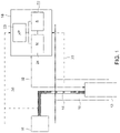
- FIG. 1 a high-level, simplified overview of aspects of a production site and control system employing a virtual flow meter are shown in FIG. 1 .
- a hydrocarbon production site is depicted.
- the site includes a downhole environment (e.g., a wellbore 10) in which a downhole tool 12 is positioned.
- the downhole tool 12 may include one or more pumps, such as electric submersible pumps (ESPs), that facilitate the movement of a production fluid 14 from the downhole environment to a downstream facility 16, such as storage tanks, separators or separation tanks, and so forth.
- ESPs electric submersible pumps
- the flow of the production fluid 14 may be controlled at least in part by the operation of the downhole tool 12 or, in alternative approaches by changing the opening of choke valves located in production manifolds, Xmas trees, a topside separator, or other flow diversion or restriction locations in the production flow path.
- the operation of the downhole tool 12 is, in this example, controlled at least in part by the operation of a controller 18 configured to implement a virtual flow meter as discussed herein.
- the downhole tool 12 in this example is depicted as being in communication with, and operated based on, the controller 18, it should be appreciated that other pumps or flow control devices may be operated based on the controller 18 in addition to or instead of the downhole tool 12.
- the controller 18 (or other similarly configured controllers 18 at the site) may control other devices or components that cause the flow of the production fluid 14 between locations at the monitored site.
- the controller 18 is a processor-based controller, having at least one microprocessor 20 to execute an algorithm corresponding to a virtual flow meter.
- the microprocessor 20 may execute stored routines corresponding to the virtual flow meter algorithm stored in a storage 22 and/or memory 24 of the controller 18.
- the processor 20 may also access sensor data 30 acquired from one or more sensor (e.g., pressure and/or temperature sensors, and/or flow rates of gas, oil, and/or water measured using multiphase flow meters) located at locations (as shown by dashed lines 30) in the fluid flow path or via the storage 22 and/or memory.
- sensor and/or operational data may be provided to the controller 18 a tool 12 responsible for the flow of the production fluid 14.
- controller 18 is depicted in FIG. 1 as a stand-alone or specially programmed device, it should be understood that the functionality the controller 18 (e.g., executing routines for implementing a virtual flow meter algorithm) may be one set of routines executed on a computer or other processor-based system that, in addition, executes other routines and performs other functions. Further, though a processor-based implementation is shown in FIG. 1 , in alternative implementations the controller 18 may be implemented as one or more application-specific integrated circuits specifically programmed to perform the routines associated with the virtual flow meter described herein when provided with the proper inputs.
- the controller 18 receives sensor input data and acts as virtual flow meter, generating an estimate of the flow of the production fluid 14 at one or more locations in the monitored site.
- the flow estimates in the depicted example may be used to generate a control signal 32 used to control the operation of one or more flow controlling devices, such as pumps, valves, and so forth.
- the control signal 32 is used to control operation of the downhole tool 12, such as an electrical submersible pump or other pumping device. In this manner, based on the flow estimated by the virtual flow meter implemented on controller 18, the operation of one or more flow controlling devices may be controlled so as to stay within desired production parameters.
- the present approach relates to the manner in which multiple sources of information in the field are merged within a common framework that allows a state space representation of the hydrocarbon production site. Such a representation then, allows the user to select a technique, e.g., the extended Kalman filter, for solving the estimation problem.
- a technique e.g., the extended Kalman filter
- the functions f and h define the relationships between input, state, and output over time.
- the input u ( k ) is missing and the output of the system depends on the values of the state vector only.
- the estimation approach can be implemented in a recursive fashion allowing minimal computational resources to be required by the algorithm such as those typically found in existing oil fields.
- the present approach focuses on stationary models which consider the case where mass flow rates and pressure are constant, or slowly varying.
- the problem of estimating mass flow rates from pressure measurement can be restated as the problem of inverting an algebraic relationship between mass flow rates and pressure values.
- a pure inversion of an algebraic relationship poses limits on the number of unknown elements that can be estimated.
- the proposed approach circumvents such a limitation by adding pseudo-measurements which model additional relationships among measured variables, or inter-relationships among different models used to represent the interaction between mass flow rates and pressure in the system.
- a suitable model related to a hydrocarbon production context may relate to a fluid-gathering-network composed of N wells, such as wells producing multiphase fluids.
- N wells such as wells producing multiphase fluids.
- the focus is on wells that produce oil, water, and gas, however other compositions such as liquid and gas, or sand, or even single phase fluids can be considered.
- the specific notation may be adapted, but the modeling and estimation approaches remain unchanged.
- m i o t denotes the mass flow rate of an oil phase generated by the i th well at time t.
- the mass flow rates of the water and gas phases are correspondingly denoted as m i w t and m i g t respectively.
- Vectors ⁇ [ m i ( t ) ⁇ represent mass flow rates at fixed temperature and pressure values. In this case, when fluids from different wells combine, mass transfer between the phases does not need to be considered and the resulting fluid is obtained by simply summing the vectors.
- FIG. 2 shows an example of a fluid-gathering network 50.
- pressure is measured at every node, with M denoting the number of nodes in the network 50 (shown in FIG. 2 ).
- Other measurements such as temperature and/or fluid rates at node locations may also be available and easily incorporated in the proposed framework.
- M is equal to 6
- N is equal to 3. That is, there are 3 wells represented in FIG. 2 and 6 measurement nodes in the connecting network.
- the relationship between mass flow rates from each of the well and the pressure values measured at the M points is obtained by combining local models of the key components of the production site. For example, every choke can be associated with a certain model that relates how the mass flow rates and pressure at its inlet and at its outlet are related.
- Known models are for example Sachdeva's or Perkins' models. Models can consider more parameters than just mass flow and pressure at the inlet.
- pipe models may depend on the geometry of the pipe as well as roughness of the internal surface. Temperature values at the inlet and outlet can also be considered. These models are known in industry and for each component the most suitable one can be selected.
- the present approach considers the case where each relevant element of the production system is associated with a model that describes the relationship between the mass flow rate at fixed pressure and temperature value that passes through the element and the value of pressure at the inlet and outlet of the element.
- the class models used to represent the relationship between mass flow rates and pressure at inlet and outlet of components of the production site are referred to herein as "Pressure Loss Models".
- Pressure Loss Segments - Elements such as pipes and chokes connect the network nodes M with each other. While flowing through these elements the fluid (e.g., production fluid 14) undergoes a reduction in pressure. Thus, these elements are referred to herein as pressure loss segments (PLSs).
- pressure loss segments are represented by the arrows connecting the nodes M. Pressure loss segments are numbered herein based on their inlet node designator. For example, the pressure loss segment connecting node A with node D may be referenced herein as pressure loss segment A (i.e., PLS A).
- the pressure loss models can be chained together so that the outlet pressure of a model becomes the inlet pressure of the adjacent element.
- the specific topology of the production network defines how inlet and outlet pressure can be mapped from one PLS to the other. With respect to FIG. 2 the outlet of the pressure loss segment C equals the inlet of the pressure loss segment E.
- the model of the production system can be summarized by two sets of equations: (i) a set of equation that describes how mass flow mixes in the production system and (ii) a set of equations that describes how outlet pressure values are related with inlet pressure values and mass flow rates. Other variables such as temperature values can also be included.
- Equation (9) defines an algebraic relationship between outlet pressure values, mass flow rates, and inlet pressure values.
- the state x(t) can be reconstructed from P out (t) only if P out ( t ) has dimension greater than or equal to x(t).
- the vector P out ( t ) has typically dimension lower than x(t) and hence, such an inversion is not possible.
- variable k is used to denote the initial time instant of the k th time interval.
- reservoir models or inflow performance relationships can be included in (12).
- equation H ( P out ( k ) ,x ( k )) 0 represents additional constraints on the system, such as equality pressure at nodal points. When additional models are considered which, for example, describe the relationship between mass flow rates, pressure, and temperatures, then these models can be included as part of the function G.
- the vector P out ( k ) has been replaced by the more generic vector y measured ( k ) which contains all of the variables directly measured in the system.
- a vector can contain the whole vector P out ( k ), or just a subset of it along with additional variables such as mass flow rates, or temperature values.
- the function G 1 can be constructed similarly to the function G and represents the so-called output function.
- the vector y pseudo ( k ) represents the vector of pseudo measurements. These measurements are not taken from real sensors. Their value is constant and typically set to 0 as defined above by the function H.
- the function H 1 defines the equality constraints relevant for the system.
- the set of equation in (14) describes the production system in a form that can be directly used for deriving estimators based on well-known approaches such as the extended Kalman Filter. In such a form, a clear definition of state, output, and pseudo-measurement is defined. Furthermore, complex system-level models are defined at run-time starting from simpler industrial-standard models for components of the overall system.
- Technical effects of the invention include higher accuracy of virtual flow meters without increasing their complexity.
- the proposed algorithm can be deployed on existing hardware, without requiring massive computational power.
- technical effects also include improved accuracy of the virtual flow meter, allowing better control the oil field by, e.g., injecting less chemicals in the system, or extracting more oil over time (increase the recovery of the field).
- a more accurate virtual flow meter supports increasing extraction from oil field and reducing management costs.
Landscapes
- Physics & Mathematics (AREA)
- Engineering & Computer Science (AREA)
- General Physics & Mathematics (AREA)
- Fluid Mechanics (AREA)
- Theoretical Computer Science (AREA)
- Mining & Mineral Resources (AREA)
- Geology (AREA)
- Life Sciences & Earth Sciences (AREA)
- Mathematical Physics (AREA)
- Pure & Applied Mathematics (AREA)
- Mathematical Analysis (AREA)
- Mathematical Optimization (AREA)
- Computational Mathematics (AREA)
- Data Mining & Analysis (AREA)
- General Engineering & Computer Science (AREA)
- Geophysics (AREA)
- Geochemistry & Mineralogy (AREA)
- General Life Sciences & Earth Sciences (AREA)
- Environmental & Geological Engineering (AREA)
- Software Systems (AREA)
- Computing Systems (AREA)
- Databases & Information Systems (AREA)
- Algebra (AREA)
- Geometry (AREA)
- Evolutionary Computation (AREA)
- Computer Hardware Design (AREA)
- Feedback Control In General (AREA)
- Measuring Volume Flow (AREA)
Claims (15)
- Virtueller Durchsatzmesser, umfassend:
eine prozessorbasierte Steuerung (18), die konfiguriert ist zum:Erzeugen oder Abrufen eines oder mehrerer Vektoren, die Massendurchsätze eines oder mehrerer Fluide durch ein Fluidsammelnetz (50) darstellen, wobei das Fluidsammelnetz (50) eine oder mehrere Quellen (A, B, C) umfasst;Erfassen von gemessenen Druckwerten für einen oder mehrere Netzknoten (A, B, C, D, E, F) innerhalb des Fluidsammelnetzes (50), wobei die Anzahl von Netzknoten größer als die Anzahl von Quellen ist;Bestimmen eines Zustandsvektors, der die Durchsätze und Druckwerte an jedem Netzknoten umfasst;Erzeugen eines Messvektors, zumindest teilweise auf Basis des Zustandsvektors; undErzeugen einer diskreten Zeitdarstellung des Fluidsammelnetzes (50), zumindest teilweise auf Basis des Zustandsvektors,des Messvektors und einer oder mehrerer Pseudomessungen,die physikalischen Zwängen in dem Fluidsammelnetz (50) entsprechen und die gegenseitigen Beziehungen zwischen verschiedenen Modellen, die verwendet werden, um die Interaktion zwischen Durchsätzen und Druck in dem Fluidsammelnetz (50) darzustellen, modellieren;wobei die eine oder die mehreren Pseudomessungen eine Dimensionalität eines Vektors erhöhen, der alle von den relevanten Ausgangsdruckwerten sammelt, um die Bestimmung des Zustandsvektors zu ermöglichen. - Virtueller Durchsatzmesser nach Anspruch 1, wobei die Steuerung (18) eine auf einem Prozessor basierende Steuerung umfasst.
- Virtueller Durchsatzmesser nach Anspruch 1, wobei die Steuerung (18) eine anwendungsspezifische integrierte Schaltung umfasst.
- Virtueller Durchsatzmesser nach Anspruch 1, wobei die Steuerung (18) ferner konfiguriert ist, um eines oder beides von Temperaturmessungen oder Fluidratenmessungen zu erfassen.
- Virtueller Durchsatzmesser nach Anspruch 1, wobei die eine oder die mehreren Pseudomessungen einen jeweils gleichen Druck an dem einen oder den mehreren Netzknoten umfassen.
- Virtueller Durchsatzmesser nach Anspruch 1, wobei die Steuerung (18) ferner konfiguriert ist, um einen Druckverlust an einem oder mehreren Druckverlustsegmenten zwischen den Netzknoten zu modellieren.
- Virtueller Durchsatzmesser nach Anspruch 6, wobei der Druckverlust an den einzelnen Druckverlustsegmenten derart modelliert wird, dass ein Auslassdruck für ein jeweiliges Druckverlustsegment eine Funktion zumindest eines Einlassdrucks für das jeweilige Druckverlustsegment und eines Durchsatzes des durch das jeweilige Druckverlustsegment fließenden Fluids ist.
- Virtueller Durchsatzmesser nach Anspruch 1, wobei der Zustandsvektor, der Messvektor und eine oder mehrere Pseudomessungen unter Verwendung eines Kalman-Filters verarbeitet werden, um ein Ausgangssignal zu erzeugen, das verwendet wird, um den Fluss innerhalb des Fluidsammelnetzes (50) zu regulieren.
- Virtueller Durchsatzmesser nach Anspruch 8, wobei der Kalman-Filter eines oder mehrere von Zustromleistungsbeziehungen, Druckkontinuität an Verbindungspunkten oder Massendurchsatzkontinuität innerhalb des Schätzungsrahmens berücksichtigt.
- Verfahren zum Überwachen eines Fluidsammelnetzes (50), wobei das Verfahren umfasst:Erzeugen oder Abrufen eines oder mehrerer Vektoren, die Massendurchsätze eines oder mehrerer Fluide durch ein Fluidsammelnetz (50) darstellen, wobei das Fluidsammelnetz (50) eine oder mehrere Quellen (A, B, C) umfasst;Erfassen von gemessenen Druckwerten für einen oder mehrere Netzknoten (A, B, C, D, E, F) innerhalb des Fluidsammelnetzes (50), wobei die Anzahl von Netzknoten größer als die Anzahl von Quellen ist;Bestimmen eines Zustandsvektors, der die Massendurchsätze und Druckwerte an jedem Netzknoten umfasst;Erzeugen eines Messvektors basierend zumindest teilweise auf dem Zustandsvektor; undErzeugen einer diskreten Zeitdarstellung des Fluidsammelnetzes (50) basierend auf zumindest dem Zustandsvektor, dem Messvektor und einer oder mehreren Pseudomessungen, die physikalischen Zwängen in dem Fluidsammelnetz (50) entsprechen und die gegenseitigen Beziehungen zwischen verschiedenen Modellen, die verwendet werden, um die Interaktion zwischen Massendurchsätzen und Druck in dem Fluidsammelnetz (50) darzustellen, modellieren;wobei die eine oder die mehreren Pseudomessungen eine Dimensionalität eines Vektors erhöhen, der alle von den relevanten Ausgangsdruckwerten sammelt, um die Bestimmung des Zustandsvektors zu ermöglichen.
- Verfahren nach Anspruch 10, ferner das Erfassen von einem oder von beidem von Temperaturmessungen oder Fluidratenmessungen umfassend.
- Verfahren nach Anspruch 10, wobei die eine oder die mehreren Pseudomessungen jeweils gleiche Drücke an dem einen oder den mehreren Netzknoten umfassen.
- Verfahren nach Anspruch 10, ferner ein Modellieren eines Druckverlustes an einem oder mehreren Druckverlustsegmenten zwischen den Netzknoten umfassend.
- Verfahren nach Anspruch 13, wobei der Druckverlust an jedem Druckverlustsegment derart modelliert wird, dass ein Auslassdruck für ein jeweiliges Druckverlustsegment eine Funktion zumindest eines Einlassdrucks für das jeweilige Druckverlustsegment und eines Massestroms des durch das jeweilige Druckverlustsegment fließenden Fluids ist.
- Ein oder mehrere computerlesbare Medien, ausführbare Routinen umfassend, die, wenn sie von einem Prozessor einer Steuerung in einem virtuellen Durchsatzmesser nach einem der Ansprüche 1-9 ausgeführt werden, bewirken, dass die Verfahrensschritte nach einem der Ansprüche 10 bis 14 durchgeführt werden.
Applications Claiming Priority (2)
| Application Number | Priority Date | Filing Date | Title |
|---|---|---|---|
| US15/265,585 US20180073904A1 (en) | 2016-09-14 | 2016-09-14 | Estimation approach for use with a virtual flow meter |
| PCT/US2017/045664 WO2018052567A1 (en) | 2016-09-14 | 2017-08-07 | Estimation approach for use with a virtual flow meter |
Publications (2)
| Publication Number | Publication Date |
|---|---|
| EP3532702A1 EP3532702A1 (de) | 2019-09-04 |
| EP3532702B1 true EP3532702B1 (de) | 2022-09-28 |
Family
ID=59677331
Family Applications (1)
| Application Number | Title | Priority Date | Filing Date |
|---|---|---|---|
| EP17754901.1A Active EP3532702B1 (de) | 2016-09-14 | 2017-08-07 | Schätzungsansatz zur verwendung mit einem virtuellen durchflussmesser |
Country Status (3)
| Country | Link |
|---|---|
| US (1) | US20180073904A1 (de) |
| EP (1) | EP3532702B1 (de) |
| WO (1) | WO2018052567A1 (de) |
Families Citing this family (7)
| Publication number | Priority date | Publication date | Assignee | Title |
|---|---|---|---|---|
| US11237550B2 (en) * | 2018-03-28 | 2022-02-01 | Honeywell International Inc. | Ultrasonic flow meter prognostics with near real-time condition based uncertainty analysis |
| WO2021069932A1 (en) * | 2019-10-11 | 2021-04-15 | Richard Steven | Improvements relating to fluid flow measurement |
| AU2022470696A1 (en) | 2022-07-22 | 2024-11-07 | Halliburton Energy Services, Inc. | Machine learning guided subsurface formation microseismic imaging |
| CN119948318A (zh) | 2022-08-05 | 2025-05-06 | 地质探索系统公司 | 流量计校准 |
| CN115452084B (zh) * | 2022-08-30 | 2024-09-03 | 中国船舶集团有限公司系统工程研究院 | 一种基于聚类算法确定加油稳定流量的方法 |
| US12332094B2 (en) | 2022-09-28 | 2025-06-17 | Halliburton Energy Services, Inc. | Machine learning-based wellbore fluid flow rate prediction |
| US12332099B2 (en) * | 2022-10-06 | 2025-06-17 | Halliburton Energy Services, Inc. | Virtual flow metering using acoustics for a well |
Citations (4)
| Publication number | Priority date | Publication date | Assignee | Title |
|---|---|---|---|---|
| US20070118346A1 (en) * | 2005-11-21 | 2007-05-24 | Chevron U.S.A. Inc. | Method, system and apparatus for real-time reservoir model updating using ensemble Kalman filter |
| US20080234939A1 (en) * | 2007-02-26 | 2008-09-25 | John Foot | Determining Fluid Rate and Phase Information for a Hydrocarbon Well Using Predictive Models |
| US20120215502A1 (en) * | 2007-12-17 | 2012-08-23 | Landmark Graphics Corporation | Systems and Methods for Optimization of Real Time Production Operations |
| US20150234880A1 (en) * | 2012-08-06 | 2015-08-20 | Agt International Gmbh | System and method for updating a data structure with sensor measurement data |
-
2016
- 2016-09-14 US US15/265,585 patent/US20180073904A1/en not_active Abandoned
-
2017
- 2017-08-07 EP EP17754901.1A patent/EP3532702B1/de active Active
- 2017-08-07 WO PCT/US2017/045664 patent/WO2018052567A1/en not_active Ceased
Patent Citations (4)
| Publication number | Priority date | Publication date | Assignee | Title |
|---|---|---|---|---|
| US20070118346A1 (en) * | 2005-11-21 | 2007-05-24 | Chevron U.S.A. Inc. | Method, system and apparatus for real-time reservoir model updating using ensemble Kalman filter |
| US20080234939A1 (en) * | 2007-02-26 | 2008-09-25 | John Foot | Determining Fluid Rate and Phase Information for a Hydrocarbon Well Using Predictive Models |
| US20120215502A1 (en) * | 2007-12-17 | 2012-08-23 | Landmark Graphics Corporation | Systems and Methods for Optimization of Real Time Production Operations |
| US20150234880A1 (en) * | 2012-08-06 | 2015-08-20 | Agt International Gmbh | System and method for updating a data structure with sensor measurement data |
Also Published As
| Publication number | Publication date |
|---|---|
| WO2018052567A1 (en) | 2018-03-22 |
| EP3532702A1 (de) | 2019-09-04 |
| US20180073904A1 (en) | 2018-03-15 |
Similar Documents
| Publication | Publication Date | Title |
|---|---|---|
| EP3532702B1 (de) | Schätzungsansatz zur verwendung mit einem virtuellen durchflussmesser | |
| US10401207B2 (en) | Method for assessing and managing sensor uncertainties in a virtual flow meter | |
| US11940318B2 (en) | Method for detection and isolation of faulty sensors | |
| CN110621846B (zh) | 从流动网络记录数据 | |
| CN103380424B (zh) | 用于在使用人工神经网络在储层模拟中模拟管道水力学的系统和方法 | |
| CN108779667B (zh) | 流动网络的评估 | |
| NO20190655A1 (en) | Time-varying flow estimation for virtual flow metering applications | |
| Haouche et al. | Virtual flow meter pilot: Based on data validation and reconciliation approach | |
| EA036893B1 (ru) | Добыча углеводородов с помощью тестового сепаратора | |
| Lu et al. | Gas lift optimization using proxy functions in reservoir simulation | |
| Schnabl et al. | Data driven virtual flow metering: Leveraging AI and edge computing for continuous multiphase flow measurement | |
| Ma et al. | Hybrid virtual flow metering on arbitrary well patterns for transient multiphase prediction driven by mechanistic and data model | |
| Bonvini et al. | An fmi-based framework for state and parameter estimation | |
| Imsland et al. | Model-based optimizing control and estimation using Modelica model | |
| Mansoori et al. | Pressure-transient analysis of bottomhole pressure and rate measurements by use of system-identification techniques | |
| NO20180207A1 (en) | A modeling framework for virtual flow metering for oil and gas applications | |
| WO2018058511A1 (en) | Sensor drift handling in virtual flow metering | |
| US20240393157A1 (en) | Methods and systems for enhancing well flow rate signal | |
| Fernandes et al. | Data-driven estimation of flowing bottom-hole pressure in petroleum wells using long short-term memory | |
| Kowalczuk et al. | Analytical steady-state model of the pipeline flow process | |
| Vinogradov et al. | Virtual flowmetering novyport field examples | |
| Ushmaev et al. | Integrated modeling as a tool for evaluating the effects of well production rates and surface gathering system performance on development of oil rim | |
| Kobzar et al. | A new approach to creating a digital twin of well for production monitoring in western Siberia fields | |
| Kobzar et al. | SPE-216731-MS | |
| Voznyuk et al. | Evolution of Integrated Models From Simplified Approach to Complex Reservoir-Well-Surface Network Representation at Different Stages of Gas Condensate Field Lifecycle |
Legal Events
| Date | Code | Title | Description |
|---|---|---|---|
| STAA | Information on the status of an ep patent application or granted ep patent |
Free format text: STATUS: UNKNOWN |
|
| STAA | Information on the status of an ep patent application or granted ep patent |
Free format text: STATUS: THE INTERNATIONAL PUBLICATION HAS BEEN MADE |
|
| PUAI | Public reference made under article 153(3) epc to a published international application that has entered the european phase |
Free format text: ORIGINAL CODE: 0009012 |
|
| STAA | Information on the status of an ep patent application or granted ep patent |
Free format text: STATUS: REQUEST FOR EXAMINATION WAS MADE |
|
| 17P | Request for examination filed |
Effective date: 20190711 |
|
| AK | Designated contracting states |
Kind code of ref document: A1 Designated state(s): AL AT BE BG CH CY CZ DE DK EE ES FI FR GB GR HR HU IE IS IT LI LT LU LV MC MK MT NL NO PL PT RO RS SE SI SK SM TR |
|
| AX | Request for extension of the european patent |
Extension state: BA ME |
|
| DAV | Request for validation of the european patent (deleted) | ||
| DAX | Request for extension of the european patent (deleted) | ||
| STAA | Information on the status of an ep patent application or granted ep patent |
Free format text: STATUS: EXAMINATION IS IN PROGRESS |
|
| 17Q | First examination report despatched |
Effective date: 20210311 |
|
| GRAP | Despatch of communication of intention to grant a patent |
Free format text: ORIGINAL CODE: EPIDOSNIGR1 |
|
| STAA | Information on the status of an ep patent application or granted ep patent |
Free format text: STATUS: GRANT OF PATENT IS INTENDED |
|
| RIC1 | Information provided on ipc code assigned before grant |
Ipc: G01F 1/74 20060101ALN20220630BHEP Ipc: E21B 47/10 20120101ALI20220630BHEP Ipc: G01F 15/00 20060101ALI20220630BHEP Ipc: E21B 47/00 20120101AFI20220630BHEP |
|
| GRAS | Grant fee paid |
Free format text: ORIGINAL CODE: EPIDOSNIGR3 |
|
| INTG | Intention to grant announced |
Effective date: 20220711 |
|
| RIN1 | Information on inventor provided before grant (corrected) |
Inventor name: GOMEZ, MARIA, GABRIELA Inventor name: THOMAS, VALENTIN, PATRICK Inventor name: PAROLINI, LUCA |
|
| GRAA | (expected) grant |
Free format text: ORIGINAL CODE: 0009210 |
|
| STAA | Information on the status of an ep patent application or granted ep patent |
Free format text: STATUS: THE PATENT HAS BEEN GRANTED |
|
| AK | Designated contracting states |
Kind code of ref document: B1 Designated state(s): AL AT BE BG CH CY CZ DE DK EE ES FI FR GB GR HR HU IE IS IT LI LT LU LV MC MK MT NL NO PL PT RO RS SE SI SK SM TR |
|
| REG | Reference to a national code |
Ref country code: GB Ref legal event code: FG4D |
|
| REG | Reference to a national code |
Ref country code: CH Ref legal event code: EP |
|
| REG | Reference to a national code |
Ref country code: DE Ref legal event code: R096 Ref document number: 602017062164 Country of ref document: DE |
|
| REG | Reference to a national code |
Ref country code: AT Ref legal event code: REF Ref document number: 1521350 Country of ref document: AT Kind code of ref document: T Effective date: 20221015 |
|
| REG | Reference to a national code |
Ref country code: IE Ref legal event code: FG4D |
|
| REG | Reference to a national code |
Ref country code: NO Ref legal event code: T2 Effective date: 20220928 |
|
| REG | Reference to a national code |
Ref country code: LT Ref legal event code: MG9D |
|
| PG25 | Lapsed in a contracting state [announced via postgrant information from national office to epo] |
Ref country code: SE Free format text: LAPSE BECAUSE OF FAILURE TO SUBMIT A TRANSLATION OF THE DESCRIPTION OR TO PAY THE FEE WITHIN THE PRESCRIBED TIME-LIMIT Effective date: 20220928 Ref country code: RS Free format text: LAPSE BECAUSE OF FAILURE TO SUBMIT A TRANSLATION OF THE DESCRIPTION OR TO PAY THE FEE WITHIN THE PRESCRIBED TIME-LIMIT Effective date: 20220928 Ref country code: LV Free format text: LAPSE BECAUSE OF FAILURE TO SUBMIT A TRANSLATION OF THE DESCRIPTION OR TO PAY THE FEE WITHIN THE PRESCRIBED TIME-LIMIT Effective date: 20220928 Ref country code: LT Free format text: LAPSE BECAUSE OF FAILURE TO SUBMIT A TRANSLATION OF THE DESCRIPTION OR TO PAY THE FEE WITHIN THE PRESCRIBED TIME-LIMIT Effective date: 20220928 Ref country code: FI Free format text: LAPSE BECAUSE OF FAILURE TO SUBMIT A TRANSLATION OF THE DESCRIPTION OR TO PAY THE FEE WITHIN THE PRESCRIBED TIME-LIMIT Effective date: 20220928 |
|
| REG | Reference to a national code |
Ref country code: NL Ref legal event code: MP Effective date: 20220928 |
|
| REG | Reference to a national code |
Ref country code: AT Ref legal event code: MK05 Ref document number: 1521350 Country of ref document: AT Kind code of ref document: T Effective date: 20220928 |
|
| PG25 | Lapsed in a contracting state [announced via postgrant information from national office to epo] |
Ref country code: HR Free format text: LAPSE BECAUSE OF FAILURE TO SUBMIT A TRANSLATION OF THE DESCRIPTION OR TO PAY THE FEE WITHIN THE PRESCRIBED TIME-LIMIT Effective date: 20220928 Ref country code: GR Free format text: LAPSE BECAUSE OF FAILURE TO SUBMIT A TRANSLATION OF THE DESCRIPTION OR TO PAY THE FEE WITHIN THE PRESCRIBED TIME-LIMIT Effective date: 20221229 |
|
| PG25 | Lapsed in a contracting state [announced via postgrant information from national office to epo] |
Ref country code: SM Free format text: LAPSE BECAUSE OF FAILURE TO SUBMIT A TRANSLATION OF THE DESCRIPTION OR TO PAY THE FEE WITHIN THE PRESCRIBED TIME-LIMIT Effective date: 20220928 Ref country code: RO Free format text: LAPSE BECAUSE OF FAILURE TO SUBMIT A TRANSLATION OF THE DESCRIPTION OR TO PAY THE FEE WITHIN THE PRESCRIBED TIME-LIMIT Effective date: 20220928 Ref country code: PT Free format text: LAPSE BECAUSE OF FAILURE TO SUBMIT A TRANSLATION OF THE DESCRIPTION OR TO PAY THE FEE WITHIN THE PRESCRIBED TIME-LIMIT Effective date: 20230130 Ref country code: ES Free format text: LAPSE BECAUSE OF FAILURE TO SUBMIT A TRANSLATION OF THE DESCRIPTION OR TO PAY THE FEE WITHIN THE PRESCRIBED TIME-LIMIT Effective date: 20220928 Ref country code: CZ Free format text: LAPSE BECAUSE OF FAILURE TO SUBMIT A TRANSLATION OF THE DESCRIPTION OR TO PAY THE FEE WITHIN THE PRESCRIBED TIME-LIMIT Effective date: 20220928 Ref country code: AT Free format text: LAPSE BECAUSE OF FAILURE TO SUBMIT A TRANSLATION OF THE DESCRIPTION OR TO PAY THE FEE WITHIN THE PRESCRIBED TIME-LIMIT Effective date: 20220928 |
|
| PG25 | Lapsed in a contracting state [announced via postgrant information from national office to epo] |
Ref country code: SK Free format text: LAPSE BECAUSE OF FAILURE TO SUBMIT A TRANSLATION OF THE DESCRIPTION OR TO PAY THE FEE WITHIN THE PRESCRIBED TIME-LIMIT Effective date: 20220928 Ref country code: PL Free format text: LAPSE BECAUSE OF FAILURE TO SUBMIT A TRANSLATION OF THE DESCRIPTION OR TO PAY THE FEE WITHIN THE PRESCRIBED TIME-LIMIT Effective date: 20220928 Ref country code: IS Free format text: LAPSE BECAUSE OF FAILURE TO SUBMIT A TRANSLATION OF THE DESCRIPTION OR TO PAY THE FEE WITHIN THE PRESCRIBED TIME-LIMIT Effective date: 20230128 Ref country code: EE Free format text: LAPSE BECAUSE OF FAILURE TO SUBMIT A TRANSLATION OF THE DESCRIPTION OR TO PAY THE FEE WITHIN THE PRESCRIBED TIME-LIMIT Effective date: 20220928 |
|
| REG | Reference to a national code |
Ref country code: DE Ref legal event code: R097 Ref document number: 602017062164 Country of ref document: DE |
|
| PG25 | Lapsed in a contracting state [announced via postgrant information from national office to epo] |
Ref country code: NL Free format text: LAPSE BECAUSE OF FAILURE TO SUBMIT A TRANSLATION OF THE DESCRIPTION OR TO PAY THE FEE WITHIN THE PRESCRIBED TIME-LIMIT Effective date: 20220928 Ref country code: AL Free format text: LAPSE BECAUSE OF FAILURE TO SUBMIT A TRANSLATION OF THE DESCRIPTION OR TO PAY THE FEE WITHIN THE PRESCRIBED TIME-LIMIT Effective date: 20220928 |
|
| P01 | Opt-out of the competence of the unified patent court (upc) registered |
Effective date: 20230526 |
|
| PG25 | Lapsed in a contracting state [announced via postgrant information from national office to epo] |
Ref country code: DK Free format text: LAPSE BECAUSE OF FAILURE TO SUBMIT A TRANSLATION OF THE DESCRIPTION OR TO PAY THE FEE WITHIN THE PRESCRIBED TIME-LIMIT Effective date: 20220928 |
|
| PLBE | No opposition filed within time limit |
Free format text: ORIGINAL CODE: 0009261 |
|
| STAA | Information on the status of an ep patent application or granted ep patent |
Free format text: STATUS: NO OPPOSITION FILED WITHIN TIME LIMIT |
|
| 26N | No opposition filed |
Effective date: 20230629 |
|
| PG25 | Lapsed in a contracting state [announced via postgrant information from national office to epo] |
Ref country code: SI Free format text: LAPSE BECAUSE OF FAILURE TO SUBMIT A TRANSLATION OF THE DESCRIPTION OR TO PAY THE FEE WITHIN THE PRESCRIBED TIME-LIMIT Effective date: 20220928 |
|
| PG25 | Lapsed in a contracting state [announced via postgrant information from national office to epo] |
Ref country code: MC Free format text: LAPSE BECAUSE OF FAILURE TO SUBMIT A TRANSLATION OF THE DESCRIPTION OR TO PAY THE FEE WITHIN THE PRESCRIBED TIME-LIMIT Effective date: 20220928 |
|
| REG | Reference to a national code |
Ref country code: CH Ref legal event code: PL |
|
| PG25 | Lapsed in a contracting state [announced via postgrant information from national office to epo] |
Ref country code: MC Free format text: LAPSE BECAUSE OF FAILURE TO SUBMIT A TRANSLATION OF THE DESCRIPTION OR TO PAY THE FEE WITHIN THE PRESCRIBED TIME-LIMIT Effective date: 20220928 |
|
| PG25 | Lapsed in a contracting state [announced via postgrant information from national office to epo] |
Ref country code: LU Free format text: LAPSE BECAUSE OF NON-PAYMENT OF DUE FEES Effective date: 20230807 |
|
| PG25 | Lapsed in a contracting state [announced via postgrant information from national office to epo] |
Ref country code: LU Free format text: LAPSE BECAUSE OF NON-PAYMENT OF DUE FEES Effective date: 20230807 Ref country code: CH Free format text: LAPSE BECAUSE OF NON-PAYMENT OF DUE FEES Effective date: 20230831 |
|
| REG | Reference to a national code |
Ref country code: BE Ref legal event code: MM Effective date: 20230831 |
|
| REG | Reference to a national code |
Ref country code: IE Ref legal event code: MM4A |
|
| PG25 | Lapsed in a contracting state [announced via postgrant information from national office to epo] |
Ref country code: IT Free format text: LAPSE BECAUSE OF FAILURE TO SUBMIT A TRANSLATION OF THE DESCRIPTION OR TO PAY THE FEE WITHIN THE PRESCRIBED TIME-LIMIT Effective date: 20220928 |
|
| PG25 | Lapsed in a contracting state [announced via postgrant information from national office to epo] |
Ref country code: IE Free format text: LAPSE BECAUSE OF NON-PAYMENT OF DUE FEES Effective date: 20230807 |
|
| PG25 | Lapsed in a contracting state [announced via postgrant information from national office to epo] |
Ref country code: IE Free format text: LAPSE BECAUSE OF NON-PAYMENT OF DUE FEES Effective date: 20230807 Ref country code: FR Free format text: LAPSE BECAUSE OF NON-PAYMENT OF DUE FEES Effective date: 20230831 |
|
| PG25 | Lapsed in a contracting state [announced via postgrant information from national office to epo] |
Ref country code: BE Free format text: LAPSE BECAUSE OF NON-PAYMENT OF DUE FEES Effective date: 20230831 |
|
| PG25 | Lapsed in a contracting state [announced via postgrant information from national office to epo] |
Ref country code: BG Free format text: LAPSE BECAUSE OF FAILURE TO SUBMIT A TRANSLATION OF THE DESCRIPTION OR TO PAY THE FEE WITHIN THE PRESCRIBED TIME-LIMIT Effective date: 20220928 |
|
| PG25 | Lapsed in a contracting state [announced via postgrant information from national office to epo] |
Ref country code: BG Free format text: LAPSE BECAUSE OF FAILURE TO SUBMIT A TRANSLATION OF THE DESCRIPTION OR TO PAY THE FEE WITHIN THE PRESCRIBED TIME-LIMIT Effective date: 20220928 |
|
| PG25 | Lapsed in a contracting state [announced via postgrant information from national office to epo] |
Ref country code: CY Free format text: LAPSE BECAUSE OF FAILURE TO SUBMIT A TRANSLATION OF THE DESCRIPTION OR TO PAY THE FEE WITHIN THE PRESCRIBED TIME-LIMIT; INVALID AB INITIO Effective date: 20170807 |
|
| PG25 | Lapsed in a contracting state [announced via postgrant information from national office to epo] |
Ref country code: HU Free format text: LAPSE BECAUSE OF FAILURE TO SUBMIT A TRANSLATION OF THE DESCRIPTION OR TO PAY THE FEE WITHIN THE PRESCRIBED TIME-LIMIT; INVALID AB INITIO Effective date: 20170807 |
|
| PGFP | Annual fee paid to national office [announced via postgrant information from national office to epo] |
Ref country code: DE Payment date: 20250724 Year of fee payment: 9 |
|
| PGFP | Annual fee paid to national office [announced via postgrant information from national office to epo] |
Ref country code: NO Payment date: 20250725 Year of fee payment: 9 |
|
| PGFP | Annual fee paid to national office [announced via postgrant information from national office to epo] |
Ref country code: GB Payment date: 20250724 Year of fee payment: 9 |
|
| PG25 | Lapsed in a contracting state [announced via postgrant information from national office to epo] |
Ref country code: TR Free format text: LAPSE BECAUSE OF FAILURE TO SUBMIT A TRANSLATION OF THE DESCRIPTION OR TO PAY THE FEE WITHIN THE PRESCRIBED TIME-LIMIT Effective date: 20220928 |