EP3532318B1 - Variable installation angle tyre pressure monitoring system - Google Patents
Variable installation angle tyre pressure monitoring system Download PDFInfo
- Publication number
- EP3532318B1 EP3532318B1 EP17837989.7A EP17837989A EP3532318B1 EP 3532318 B1 EP3532318 B1 EP 3532318B1 EP 17837989 A EP17837989 A EP 17837989A EP 3532318 B1 EP3532318 B1 EP 3532318B1
- Authority
- EP
- European Patent Office
- Prior art keywords
- valve
- tyre
- hinge joint
- enclosure
- rotatable member
- Prior art date
- Legal status (The legal status is an assumption and is not a legal conclusion. Google has not performed a legal analysis and makes no representation as to the accuracy of the status listed.)
- Active
Links
Images



Classifications
-
- B—PERFORMING OPERATIONS; TRANSPORTING
- B60—VEHICLES IN GENERAL
- B60C—VEHICLE TYRES; TYRE INFLATION; TYRE CHANGING; CONNECTING VALVES TO INFLATABLE ELASTIC BODIES IN GENERAL; DEVICES OR ARRANGEMENTS RELATED TO TYRES
- B60C29/00—Arrangements of tyre-inflating valves to tyres or rims; Accessories for tyre-inflating valves, not otherwise provided for
- B60C29/02—Connection to rims
-
- B—PERFORMING OPERATIONS; TRANSPORTING
- B60—VEHICLES IN GENERAL
- B60C—VEHICLE TYRES; TYRE INFLATION; TYRE CHANGING; CONNECTING VALVES TO INFLATABLE ELASTIC BODIES IN GENERAL; DEVICES OR ARRANGEMENTS RELATED TO TYRES
- B60C23/00—Devices for measuring, signalling, controlling, or distributing tyre pressure or temperature, specially adapted for mounting on vehicles; Arrangement of tyre inflating devices on vehicles, e.g. of pumps or of tanks; Tyre cooling arrangements
- B60C23/02—Signalling devices actuated by tyre pressure
- B60C23/04—Signalling devices actuated by tyre pressure mounted on the wheel or tyre
- B60C23/0491—Constructional details of means for attaching the control device
- B60C23/0494—Valve stem attachments positioned inside the tyre chamber
Definitions
- the present invention relates to an assembly comprising a tyre valve and an enclosure, wherein the enclosure is adapted to receive a gas pressure monitoring unit, wherein the enclosure comprises a hinge joint, the hinge joint having at least one stationary member connected to the enclosure, an axle and a rotatable member arranged to at least partially rotate around the axle and wherein the tyre valve is connected to the rotatable member of the hinge joint.
- the invention also relates to a tyre wheel comprising an assembly according to the invention.
- one tyre pressure sensor is arranged, respectively, on each tyre or pneumatic tyre.
- a tyre pressure sensor often comprises at least one sensor for detecting the tyre pressure or the temperature, as well as one transmission unit and, if required, one electronic evaluation unit, which can also be on-board.
- TPMS tyre pressure monitoring systems
- EP 2 857 228 A1 discloses a tyre pressure sensor installed on a tyre rim, the tyre rim comprising an assembly through hole; the tyre pressure sensor comprising: a sensor body, comprising: a gas nozzle assembly hole; a tyre pressure sensing module disposed in the sensor body for detecting a tyre pressure, including a control unit which saves a firmware for controlling operation of the tyre pressure sensing module; and an update connection port electrically connecting to the tyre pressure sensing module, wherein the control unit receives an update firmware data through the update connection port for updating the firmware; a gas intake nozzle, comprising: a coupling section inserted into the gas nozzle assembly hole; and a gas intake section connecting to the coupling section, penetrating through the assembly through hole, and extending towards a direction outside the tyre rim for gas to input; and a gas nozzle assembly member, penetrating through the gas nozzle assembly hole to couple with
- a tyre monitoring sensor comprises two main parts: valve and sensor.
- the tyre pressure monitoring sensor is mounted at the position of the tyre valve which is mounted on the rim. Since the valve onto the rim mounting surface and the vertical direction has a mounting angle subtended, for tyres of different specifications the installation angle of the valve on the rim angle is different. That is to say, tyres of different specifications, installation of the valve on the rim angle is different.
- a tyre monitoring sensor with a fixed angle between the sensor housing and the valve can only be mounted to a specific rim type only. If mounted to a different rim, this can cause damage to and subsequent failure of the sensor housing while mounting and demounting of tyre.
- CN 202186246 U relates to a tyre pressure monitoring sensor with an adjustable installation angle, comprising a sensor shell and an inflating valve, wherein the sensor shell is movably connected with the inflating valve through a movement pair; the movement pair comprises an inflating valve connector and a pin; a bracket is arranged on the top part of the sensor shell; the bracket is movably connected with the inflating valve connector through the pin, and the inflating valve connector is fixedly connected with one end of the inflating valve.
- An included angle between the sensor shell and the inflating valve can be adjustable and fixed at any position from -90 to 90 degrees so that the tyre pressure monitoring sensor is reported to be suitable for automobile tyres with different types of rims and can better avoid failure risk caused by improper installation angle.
- the drawback of the solution as disclosed in this Chinese utility model is that the valve is merely slid onto the valve connector without any form-fitting fastening arrangements. This necessitates additional measures to secure the assembly to prevent a separation of the valve and the sensor shell.
- US 2012/017672 A1 discloses a tyre pressure sensor comprising: a tyre pressure sensor housing installed on a side portion of a wheel to sense air pressure of a tyre; an angle-adjustable tyre valve coupled to the tyre pressure sensor housing, having an end exposed out of the wheel through a wheel valve hole, and including a male screw part on a middle outer surface; a rubber grommet disposed on an inner surface corresponding to the wheel valve hole to prevent air from leaking out of the tyre;a washer fitted on the tyre valve to support the rubber grommet; and a fastening nut coupled to the male screw part of the tyre valve.
- the construction as disclosed in this patent application has the disadvantage that the extent to which the valve can be angled with respect to the sensor housing is fairly limited.
- CN 103 317 980 A discloses an assembly structure for a tire pressure transmitter and an inflating valve including an inflating valve joint, a small shaft, a fastening screw and a tire pressure transmitter connecting member.
- the inflating valve joint has a lateral through hole diverging from the axis of the inflating valve joint in the downward direction.
- the tire pressure transmitter connecting member has an axial screw hole, one side of the screw hole is provided with a pivoting base, and the pivoting seat is provided with a pair of pivoting holes.
- the inflating valve joint is used for connecting an inflating valve;
- the tire pressure transmitter connecting member is used for combining with a housing of the tire pressure transmitter;
- the inflating valve joint is arranged on a pivoting part of the tire pressure transmitter connecting member;
- the small shaft passes through the pair of pivoting holes and the through hole of the inflating valve joint;
- the fastening screw is screwed into the screw hole of the tire pressure transmitter connecting member, when bearing against the end face of the inflating valve joint, the fastening screw goes on being screwed, so that the housing of the tire pressure transmitter rotates around the small shaft with the top end of the fastening screw as a fulcrum, until supporting points of the housing support to a tire rim.
- CN 101 980 885 A discloses an angle adjustable tire pressure sensing device, which comprises a sensor and an inflating valve.
- the sensor is used for detecting and transmitting the tire pressure and is provided with a signal shell; and the inflating valve is inserted into a rim hole of a rim and is provided with a valve rod which is used for connecting the signal shell.
- a cross nut which rotates around a rotating shaft is arranged on the signal shell and is provided with a screw hole vertical to the rotating shaft; and the signal shell is provided with a pressure-bearing surface raising along the direction away from the screw hole on one side of the screw hole away from the valve rod.
- the valve rod is provided with a thread section and an end part.
- valve rod and the signal shell arecombined, by screwing the thread section of the valve rod and the screw hole of the cross nut, the end part of the valve rod passes through the screw hole of the cross nut to be pressed on the pressure-bearing surface, while the signal shell is pressed on a rim surface of the rim.
- the thread section of the valve rod screws in the cross nut, the position where the end part of the valve rod is pressed on the pressure-bearing surface moves, so that the valve rod changes relative to an inclination angle of a reference surface so as to adapt to the rim surfaces at different angles.
- CN 105 196 806 A discloses a tire gauge comprising a tire gauge main body and an inflating valve assembly, wherein the tire gauge main body comprises a shell, a PCB assembly contained in the shell, a battery, and a metal connection piece locally extending out of the shell; air inlets are formed in the shell; the shell comprises a front panel; a first shaft seat is arranged at the outer side of the front plane; a first shaft hole is formed in the first shaft seat; the metal connection piece comprises a second shaft scat; a first shaft hole is also formed in the second shaft scat; the second shaft scat is provided with a first screw column around the first shaft hole; a swinging groove is defined by the first shaft seat and the second shaft seat; the inflating valve assembly comprises a swinging head which is provided with a second shaft hole and is arranged in the swinging groove; a bolt penetrates through the first shaft hole of the first shaft seat, the second shaft hole of the swinging head and the first shaft hole of the second shaft seat in sequence to
- GB 2 407 383A discloses a tyre pressure monitoring apparatus 10, for mounting on a vehicle wheel 12 that is configured to have a tyre 14 mounted thereon and that has a first opening 16 includes a tyre monitor 18 for sensing pressure in the tyre (14).
- the tyre monitor 18 includes a housing 24 having a spherical surface 26 and a second opening 28 that extends though the spherical surface 26.
- a tyre valve stem 30 is configured to extend though the first and second openings 16,28, and the valve stem 30 has a threaded portion 40.
- the apparatus further includes a threaded fastener 21 that is engageable with the threaded portion 40 of the valve stem 30 for attaching together the tyre monitor 18 and the valve stem 30.
- the fastener 21 has a spherical surface 42 that is engageable with the spherical surface 26 of the housing 24 when the fastener 21 is engaged with the threaded portion 40 of the valve stem 30.
- the fastener 21 includes multiple first engaging members (50 fig. 3 , not shown) and multiple second engaging members (54).
- the present invention has the object of at least partially overcoming the drawbacks of the prior art.
- the present invention has the object of providing a tyre pressure monitoring system where the valve is securely fastened to the housing and where the angle between valve and housing can be set to large angles.
- a tyre wheel comprising an assembly according to the invention is the subject of claim 10.
- Advantageous embodiments of the invention are the subject of dependent claims. They can be combined freely unless the context clearly indicates otherwise.
- the tyre valve is rotatably coupled to the enclosure and, for example, has a freedom of rotating at an angle that allows it to be fixed on rims for tyres with different profiles.
- a suitable tyre valve 2 may, for example, be a valve for automobile tyres, truck tyres or tractor tyres.
- the enclosure 3 is adapted to receive a gas pressure monitoring unit. Then the enclosure 3 can act as a carrier for the monitoring unit.
- the enclosure 3 may be an open enclosure as depicted in FIG. 1 , a partially sealed enclosure or a sealed enclosure (provided that the gas pressure monitoring unit can still fulfil its function).
- the enclosure 3 comprises a hinge joint, the hinge joint having at least one stationary member connected to the enclosure 3, an axle 6 and a rotatable member 5 arranged to at least partially rotate around the axle.
- the hinge joint comprises two stationary members and an axle 6.
- the hinge joint's rotatable member 5 is sandwiched between two washers 4, which may be serrated washers, when assembled in order to ensure a snug fit of the member 5.
- the tyre valve 2 is connected to the rotatable member 5 of the hinge joint.
- the tyre valve 2 is connected to the rotatable member 5 of the hinge joint by a form-fitting connection which secures the tyre valve 2 against movement in a direction towards the rotatable member 5 and in a direction away from the rotatable member 5.
- the tyre valve 2 cannot move along an axis perpendicular to the axle of the hinge joint, even if a force is applied in the respective directions.
- the tyre valve 2 is immobilized with respect to its connection to the rotatable member 5 even in the presence of a force.
- the form-fitting connection is a releasable connection to allow easy fitting of the assembly into a tyre wheel. Examples for suitable form-fitting connections are screw connections and bayonet connections.
- the rotatable member 5 of the hinge joint comprises an extension to which the tyre valve is connected.
- This extension is also depicted in the assembly of FIG. 1 .
- the extension creates an offset from the axis defined by the axle 6 of the hinge joint and introduces a greater flexibility for the possible range of motion for the tyre valve 2 with respect to the housing 3.
- the tyre valve 2 has an at least partially threaded extension which is fastened to the rotatable member 5 of the hinge joint.
- the at least partially threaded extension of the tyre valve 2 is screwed into a thread provided by the rotatable member 5 of the hinge joint.
- the least partially threaded extension of the tyre valve 2 is fastened to the rotatable member 5 of the hinge joint via a threaded nut. This is depicted in FIG. 1 where a threaded extension of the valve 2 reaches through the extension of the rotatable member and is secured on the opposing side by a threaded nut.
- axle 6 of the hinge joint is an at least partially threaded bolt. This is depicted in FIG. 1 where a torque nut 7 is used to secure the axle 6 in the hinge joint.
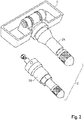
- FIG. 2 shows a perspective view of an assembly according to the invention with enclosure 3 and a tyre valve.
- the tyre valve connected to the enclosure 3 is designated 2A whereas an unconnected tyre valve of a slightly different exterior configuration with a nut at the end of the threaded extension is designated 2B.
- the enclosure 3 comprises a recess adapted to increase the range of motion of the valve 2. For example, as shown in FIG. 3 , an angular range of -90 to +90 degrees can be realized. This allows the assembly to be affixed onto tyre rims with vastly different profiles and can avoid failure risk due to an improper installation angle while mounting and demounting of tyre.
- the assembly according to the invention further comprises a gas pressure monitoring unit within the enclosure 3.
- This unit may comprise a printed circuit board, sensor, battery and other electronic parts for sensing the gas pressure and temperature inside the tyre.
- the gas pressure monitoring unit comprises radio transmission circuitry in electrical communication with the valve 2 and the valve 2 acts as an antenna of the radio transmission circuitry.
- the valve 2 acting as an antenna may connected to the transmission circuitry by means of a feeder.
- the invention is further directed to a tyre wheel 1 comprising an assembly according to the invention.
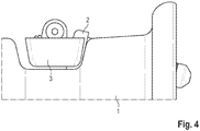
- FIG. 4 and FIG. 5 show such configurations in a side view and a perspective view.
Landscapes
- Engineering & Computer Science (AREA)
- Mechanical Engineering (AREA)
- Measuring Fluid Pressure (AREA)
Description
- The present invention relates to an assembly comprising a tyre valve and an enclosure, wherein the enclosure is adapted to receive a gas pressure monitoring unit, wherein the enclosure comprises a hinge joint, the hinge joint having at least one stationary member connected to the enclosure, an axle and a rotatable member arranged to at least partially rotate around the axle and wherein the tyre valve is connected to the rotatable member of the hinge joint. The invention also relates to a tyre wheel comprising an assembly according to the invention.
- Vehicle safety and reliability are central aspects of automotive technology. Therefore, for safety-related reasons alone, the tyre pressure of motor vehicles should be regularly monitored which, however, is often neglected by the driver. For this reason, an increasing number of modern vehicles are equipped with detecting means in the form of tyre pressure sensors, which measure the pressure in the tyres automatically and transmit it to an on-board control device. In this way, accidents or defects resulting from low tyre pressure should be avoided. Such automatic measuring of the tyre pressure makes it possible to detect early and indicate to the driver when the tyre pressure critically deviates from a tyre pressure nominal value, thus making a manual inspection unnecessary. In such systems for automatic measuring of the tyre pressure, one tyre pressure sensor is arranged, respectively, on each tyre or pneumatic tyre. At the same time, a tyre pressure sensor often comprises at least one sensor for detecting the tyre pressure or the temperature, as well as one transmission unit and, if required, one electronic evaluation unit, which can also be on-board.
- Most of the tyre pressure monitoring systems (TPMS) available on the market use directly measuring pressure sensors that are assigned to the valve and transmit the tyre pressure value measured by the pressure sensor by way of an electronic system of the wheel equipped with a transmission antenna to a receiving device in the vehicle, which then in turn indicates the measured value by way of the electronic system of the vehicle and, if it is below a prescribed value, possibly triggers a warning signal.
- For example,
EP 2 857 228 A1 - A tyre monitoring sensor comprises two main parts: valve and sensor. In use, the tyre pressure monitoring sensor is mounted at the position of the tyre valve which is mounted on the rim. Since the valve onto the rim mounting surface and the vertical direction has a mounting angle subtended, for tyres of different specifications the installation angle of the valve on the rim angle is different. That is to say, tyres of different specifications, installation of the valve on the rim angle is different. Hence, a tyre monitoring sensor with a fixed angle between the sensor housing and the valve can only be mounted to a specific rim type only. If mounted to a different rim, this can cause damage to and subsequent failure of the sensor housing while mounting and demounting of tyre.
- Numerous attempts have been made in the prior art to provide tyre pressure monitoring systems with variable angles between the valve and the sensor or the sensor housing.
CN 202186246 U relates to a tyre pressure monitoring sensor with an adjustable installation angle, comprising a sensor shell and an inflating valve, wherein the sensor shell is movably connected with the inflating valve through a movement pair; the movement pair comprises an inflating valve connector and a pin; a bracket is arranged on the top part of the sensor shell; the bracket is movably connected with the inflating valve connector through the pin, and the inflating valve connector is fixedly connected with one end of the inflating valve. An included angle between the sensor shell and the inflating valve can be adjustable and fixed at any position from -90 to 90 degrees so that the tyre pressure monitoring sensor is reported to be suitable for automobile tyres with different types of rims and can better avoid failure risk caused by improper installation angle. The drawback of the solution as disclosed in this Chinese utility model is that the valve is merely slid onto the valve connector without any form-fitting fastening arrangements. This necessitates additional measures to secure the assembly to prevent a separation of the valve and the sensor shell. -
US 2012/017672 A1 discloses a tyre pressure sensor comprising: a tyre pressure sensor housing installed on a side portion of a wheel to sense air pressure of a tyre; an angle-adjustable tyre valve coupled to the tyre pressure sensor housing, having an end exposed out of the wheel through a wheel valve hole, and including a male screw part on a middle outer surface; a rubber grommet disposed on an inner surface corresponding to the wheel valve hole to prevent air from leaking out of the tyre;a washer fitted on the tyre valve to support the rubber grommet; and a fastening nut coupled to the male screw part of the tyre valve. The construction as disclosed in this patent application has the disadvantage that the extent to which the valve can be angled with respect to the sensor housing is fairly limited. -
CN 103 317 980 A discloses an assembly structure for a tire pressure transmitter and an inflating valve including an inflating valve joint, a small shaft, a fastening screw and a tire pressure transmitter connecting member. The inflating valve joint has a lateral through hole diverging from the axis of the inflating valve joint in the downward direction. The tire pressure transmitter connecting member has an axial screw hole, one side of the screw hole is provided with a pivoting base, and the pivoting seat is provided with a pair of pivoting holes. The inflating valve joint is used for connecting an inflating valve; the tire pressure transmitter connecting member is used for combining with a housing of the tire pressure transmitter; the inflating valve joint is arranged on a pivoting part of the tire pressure transmitter connecting member; the small shaft passes through the pair of pivoting holes and the through hole of the inflating valve joint; the fastening screw is screwed into the screw hole of the tire pressure transmitter connecting member, when bearing against the end face of the inflating valve joint, the fastening screw goes on being screwed, so that the housing of the tire pressure transmitter rotates around the small shaft with the top end of the fastening screw as a fulcrum, until supporting points of the housing support to a tire rim. -
CN 101 980 885 A discloses an angle adjustable tire pressure sensing device, which comprises a sensor and an inflating valve. The sensor is used for detecting and transmitting the tire pressure and is provided with a signal shell; and the inflating valve is inserted into a rim hole of a rim and is provided with a valve rod which is used for connecting the signal shell. A cross nut which rotates around a rotating shaft is arranged on the signal shell and is provided with a screw hole vertical to the rotating shaft; and the signal shell is provided with a pressure-bearing surface raising along the direction away from the screw hole on one side of the screw hole away from the valve rod. The valve rod is provided with a thread section and an end part. When the valve rod and the signal shell arecombined, by screwing the thread section of the valve rod and the screw hole of the cross nut, the end part of the valve rod passes through the screw hole of the cross nut to be pressed on the pressure-bearing surface, while the signal shell is pressed on a rim surface of the rim. As the thread section of the valve rod screws in the cross nut, the position where the end part of the valve rod is pressed on the pressure-bearing surface moves, so that the valve rod changes relative to an inclination angle of a reference surface so as to adapt to the rim surfaces at different angles. -
CN 105 196 806 A discloses a tire gauge comprising a tire gauge main body and an inflating valve assembly, wherein the tire gauge main body comprises a shell, a PCB assembly contained in the shell, a battery, and a metal connection piece locally extending out of the shell; air inlets are formed in the shell; the shell comprises a front panel; a first shaft seat is arranged at the outer side of the front plane; a first shaft hole is formed in the first shaft seat; the metal connection piece comprises a second shaft scat; a first shaft hole is also formed in the second shaft scat; the second shaft scat is provided with a first screw column around the first shaft hole; a swinging groove is defined by the first shaft seat and the second shaft seat; the inflating valve assembly comprises a swinging head which is provided with a second shaft hole and is arranged in the swinging groove; a bolt penetrates through the first shaft hole of the first shaft seat, the second shaft hole of the swinging head and the first shaft hole of the second shaft seat in sequence to be connected with the first screw column. According to the tire gauge, the angle between the tire gauge main body and the inflating valve assembly can be adjusted, so that tires with different rims can be installed. -
GB 2 407 383A pressure monitoring apparatus 10, for mounting on a vehicle wheel 12 that is configured to have a tyre 14 mounted thereon and that has a first opening 16 includes a tyre monitor 18 for sensing pressure in the tyre (14). The tyre monitor 18 includes a housing 24 having a spherical surface 26 and a second opening 28 that extends though the spherical surface 26. A tyre valve stem 30 is configured to extend though the first and second openings 16,28, and the valve stem 30 has a threaded portion 40. The apparatus further includes a threaded fastener 21 that is engageable with the threaded portion 40 of the valve stem 30 for attaching together the tyre monitor 18 and the valve stem 30. The fastener 21 has a spherical surface 42 that is engageable with the spherical surface 26 of the housing 24 when the fastener 21 is engaged with the threaded portion 40 of the valve stem 30. The fastener 21 includes multiple first engaging members (50fig. 3 , not shown) and multiple second engaging members (54). - The present invention has the object of at least partially overcoming the drawbacks of the prior art. In particular, the present invention has the object of providing a tyre pressure monitoring system where the valve is securely fastened to the housing and where the angle between valve and housing can be set to large angles.
- This object is achieved by an assembly comprising a tyre valve and an enclosure according to
claim 1. A tyre wheel comprising an assembly according to the invention is the subject ofclaim 10. Advantageous embodiments of the invention are the subject of dependent claims. They can be combined freely unless the context clearly indicates otherwise. - The tyre valve is rotatably coupled to the enclosure and, for example, has a freedom of rotating at an angle that allows it to be fixed on rims for tyres with different profiles.
- The invention will be further described with reference to the following figures without wishing to be limited by them.
- FIG. 1
- shows an exploded view of an assembly comprising a tyre valve and an enclosure according to the invention
- FIG. 2
- shows an assembly comprising a tyre valve and an enclosure according to the invention
- FIG. 3
- shows an assembly comprising a tyre valve and an enclosure according to the invention
- FIG. 4
- shows an assembly comprising a tyre valve and an enclosure according to the invention mounted onto a tyre rim
- FIG. 5
- shows an assembly comprising a tyre valve and an enclosure according to the invention mounted onto a tyre rim
- Referring to
FIG. 1 , an assembly comprising atyre valve 2 and anenclosure 3 according to the invention is shown. Asuitable tyre valve 2 may, for example, be a valve for automobile tyres, truck tyres or tractor tyres. Theenclosure 3 is adapted to receive a gas pressure monitoring unit. Then theenclosure 3 can act as a carrier for the monitoring unit. Theenclosure 3 may be an open enclosure as depicted inFIG. 1 , a partially sealed enclosure or a sealed enclosure (provided that the gas pressure monitoring unit can still fulfil its function). - The
enclosure 3 comprises a hinge joint, the hinge joint having at least one stationary member connected to theenclosure 3, an axle 6 and arotatable member 5 arranged to at least partially rotate around the axle. In theenclosure 3 depicted inFIG. 1 the hinge joint comprises two stationary members and an axle 6. The hinge joint'srotatable member 5, is sandwiched between two washers 4, which may be serrated washers, when assembled in order to ensure a snug fit of themember 5. These components not only performs the function of holding theenclosure 3 to thetyre valve 2 but also arresting the freedom of rotation of the enclosure with respect to the valve at any desired angle. - According to the invention the
tyre valve 2 is connected to therotatable member 5 of the hinge joint. In particular, thetyre valve 2 is connected to therotatable member 5 of the hinge joint by a form-fitting connection which secures thetyre valve 2 against movement in a direction towards therotatable member 5 and in a direction away from therotatable member 5. Hence thetyre valve 2 cannot move along an axis perpendicular to the axle of the hinge joint, even if a force is applied in the respective directions. Preferably thetyre valve 2 is immobilized with respect to its connection to therotatable member 5 even in the presence of a force. It is further preferred that the form-fitting connection is a releasable connection to allow easy fitting of the assembly into a tyre wheel. Examples for suitable form-fitting connections are screw connections and bayonet connections. - In an embodiment of the assembly according to the invention the
rotatable member 5 of the hinge joint comprises an extension to which the tyre valve is connected. This extension is also depicted in the assembly ofFIG. 1 . The extension creates an offset from the axis defined by the axle 6 of the hinge joint and introduces a greater flexibility for the possible range of motion for thetyre valve 2 with respect to thehousing 3. - In another embodiment of the assembly according to the invention the
tyre valve 2 has an at least partially threaded extension which is fastened to therotatable member 5 of the hinge joint. - In another embodiment of the assembly according to the invention the at least partially threaded extension of the
tyre valve 2 is screwed into a thread provided by therotatable member 5 of the hinge joint. - In another embodiment of the assembly according to the invention the least partially threaded extension of the
tyre valve 2 is fastened to therotatable member 5 of the hinge joint via a threaded nut. This is depicted inFIG. 1 where a threaded extension of thevalve 2 reaches through the extension of the rotatable member and is secured on the opposing side by a threaded nut. - In another embodiment of the assembly according to the invention the axle 6 of the hinge joint is an at least partially threaded bolt. This is depicted in
FIG. 1 where atorque nut 7 is used to secure the axle 6 in the hinge joint. -
FIG. 2 shows a perspective view of an assembly according to the invention withenclosure 3 and a tyre valve. The tyre valve connected to theenclosure 3 is designated 2A whereas an unconnected tyre valve of a slightly different exterior configuration with a nut at the end of the threaded extension is designated 2B. - In another embodiment of the assembly according to the invention the
enclosure 3 comprises a recess adapted to increase the range of motion of thevalve 2. For example, as shown inFIG. 3 , an angular range of -90 to +90 degrees can be realized. This allows the assembly to be affixed onto tyre rims with vastly different profiles and can avoid failure risk due to an improper installation angle while mounting and demounting of tyre. - In another embodiment the assembly according to the invention further comprises a gas pressure monitoring unit within the
enclosure 3. This unit may comprise a printed circuit board, sensor, battery and other electronic parts for sensing the gas pressure and temperature inside the tyre. - In another embodiment of the assembly according to the invention the gas pressure monitoring unit comprises radio transmission circuitry in electrical communication with the
valve 2 and thevalve 2 acts as an antenna of the radio transmission circuitry. Thevalve 2 acting as an antenna may connected to the transmission circuitry by means of a feeder. - The invention is further directed to a
tyre wheel 1 comprising an assembly according to the invention.FIG. 4 andFIG. 5 show such configurations in a side view and a perspective view.
Claims (8)
- An assembly comprising a tyre valve (2) and an enclosure (3),
wherein the enclosure (3) is adapted to receive a gas pressure monitoring unit,
wherein the enclosure (3) comprises a hinge joint, the hinge joint having at least one stationary member connected to the enclosure (3), an axle (6) and a rotatable member (5) arranged to at least partially rotate around the axle (6),
wherein the tyre valve (2) is connected to the rotatable member (5) of the hinge joint,
characterized in that
the tyre valve (2) is connected to the rotatable member (5) of the hinge joint by a form-fitting connection which secures the tyre valve (2) against movement in a direction towards the rotatable member (5) and in a direction away from the rotatable member (5), wherein the rotatable member (5) of the hinge joint comprises an extension to which the tyre valve is connected, and wherein the tyre valve (2) has an at least partially threaded extension which is fastened to the rotatable member (5) of the hinge joint. - The assembly according to claim 1, wherein the at least partially threaded extension of the tyre valve (2) is screwed into a thread provided by the rotatable member (5) of the hinge joint.
- The assembly according to claim 1, wherein the least partially threaded extension of the tyre valve (2) is fastened to the rotatable member (5) of the hinge joint via a threaded nut.
- The assembly according to one of claims 1 to 3, wherein the axle (6) of the hinge joint is an at least partially threaded bolt.
- The assembly according to one of claims 1 to 4, wherein the enclosure (3) comprises a recess adapted to increase the range of motion of the valve (2).
- The assembly according to one of claims 1 to 5, further comprising a gas pressure monitoring unit within the enclosure (3).
- The assembly according to claim 6, wherein the gas pressure monitoring unit comprises radio transmission circuitry in electrical communication with the valve (2) and wherein the valve (2) acts as an antenna of the radio transmission circuitry.
- A tyre wheel (1) comprising an assembly according to one of claims 1 to 7.
Applications Claiming Priority (2)
| Application Number | Priority Date | Filing Date | Title |
|---|---|---|---|
| IN201641037034 | 2016-10-28 | ||
| PCT/IB2017/056688 WO2018078576A1 (en) | 2016-10-28 | 2017-10-27 | Variable installation angle tyre pressure monitoring system |
Publications (2)
| Publication Number | Publication Date |
|---|---|
| EP3532318A1 EP3532318A1 (en) | 2019-09-04 |
| EP3532318B1 true EP3532318B1 (en) | 2021-06-16 |
Family
ID=61148263
Family Applications (1)
| Application Number | Title | Priority Date | Filing Date |
|---|---|---|---|
| EP17837989.7A Active EP3532318B1 (en) | 2016-10-28 | 2017-10-27 | Variable installation angle tyre pressure monitoring system |
Country Status (3)
| Country | Link |
|---|---|
| US (1) | US10960715B2 (en) |
| EP (1) | EP3532318B1 (en) |
| WO (1) | WO2018078576A1 (en) |
Cited By (1)
| Publication number | Priority date | Publication date | Assignee | Title |
|---|---|---|---|---|
| US20230091982A1 (en) * | 2021-09-23 | 2023-03-23 | Wonder S.P.A. | Tire inflation valve equipped with adjusting system for a tpms sensor |
Families Citing this family (9)
| Publication number | Priority date | Publication date | Assignee | Title |
|---|---|---|---|---|
| WO2018122924A1 (en) * | 2016-12-26 | 2018-07-05 | 太平洋工業 株式会社 | Tire condition detecting apparatus, clamp-in valve and tire valve unit |
| DE102019119995A1 (en) | 2018-07-31 | 2020-02-06 | Sensata Technologies, Inc. | TIRE PRESSURE MONITOR WITH VARIABLE ANGLE MOUNTING |
| US10807421B2 (en) * | 2018-07-31 | 2020-10-20 | Sensata Techologies, Inc. | Tire pressure monitor with variable angle mounting |
| US11813900B2 (en) | 2018-12-05 | 2023-11-14 | Continental Automotive Gmbh | Housing for a tyre parameter monitoring system, tyre parameter monitoring system and method for mounting a tyre parameter monitoring system to a rim of a wheel |
| GB2580379B (en) * | 2019-01-08 | 2021-06-16 | Continental Automotive Gmbh | Housing for a tyre parameter monitoring system, tyre parameter monitoring system and method for mounting a tyre parameter monitoring system |
| CN112537176B (en) * | 2019-09-20 | 2022-12-20 | 大陆汽车有限公司 | Adapter, valve stem, tire parameter monitoring system and method for mounting a tire parameter monitoring system on a rim |
| GB2589141B (en) * | 2019-11-25 | 2021-12-29 | Continental Automotive Gmbh | Adapter, valve stem, tyre parameter monitoring system and method for mounting a tyre parameter monitoring system onto a wheel rim |
| CN110954166B (en) * | 2019-12-03 | 2021-10-12 | 日照安泰科技发展有限公司 | Indoor environmental data collection device that can integral type installation |
| EP3865319B1 (en) * | 2020-02-14 | 2023-04-05 | Continental Automotive Technologies GmbH | Valve system, tyre parameter monitoring system and method for mounting a tyre parameter monitoring system onto a wheel rim of a vehicle |
Family Cites Families (14)
| Publication number | Priority date | Publication date | Assignee | Title |
|---|---|---|---|---|
| US6945104B2 (en) * | 2003-10-24 | 2005-09-20 | Lear Corporation | Attachment mechanism for a tire monitoring system |
| US6952955B1 (en) * | 2004-07-28 | 2005-10-11 | Lear Corporation | Adjustable mounting of tire monitoring assembly |
| FR2907048B1 (en) * | 2006-10-16 | 2014-05-02 | Siemens Vdo Automotive | ELECTRONIC UNIT FOR MEASURING OPERATING PARAMETERS OF A VEHICLE WHEEL. |
| CN200988401Y (en) * | 2006-11-29 | 2007-12-12 | 上海保隆汽车科技股份有限公司 | Combined device of stepless adjustable tire pressure monitoring sensor signal box |
| CN200988402Y (en) * | 2006-12-04 | 2007-12-12 | 上海保隆汽车科技股份有限公司 | Combined device for stepped adjustable tire pressure monitoring sensor signal box |
| KR101137813B1 (en) | 2009-04-01 | 2012-04-18 | 씨트론 주식회사 | Tire Pressure Monitoring System and Tire Pressure Sensor thereof |
| CN101890885B (en) * | 2009-05-22 | 2013-07-31 | 上海保隆汽车科技股份有限公司 | Angle adjustable tire pressure sensing device |
| CN202186246U (en) | 2011-07-04 | 2012-04-11 | 联创汽车电子有限公司 | Tire pressure monitoring sensor with adjustable installation angle |
| CN103317980B (en) | 2012-03-23 | 2017-05-03 | 上海保隆汽车科技股份有限公司 | Assembly structure for tire pressure transmitter and inflating valve |
| US9315079B2 (en) * | 2013-10-02 | 2016-04-19 | Sung Jung Minute Industry Co., Ltd | Adjustable tire pressure detector |
| US9238389B2 (en) * | 2013-10-02 | 2016-01-19 | Sung Jung Minute Industry Co., Ltd | Adjustable tire pressure detector |
| EP2857228B1 (en) | 2013-10-07 | 2016-02-03 | Sung Jung Minute Industry Co., Ltd. | Tire pressure sensor |
| CN105196806B (en) | 2015-10-12 | 2017-06-30 | 铁将军汽车电子有限公司 | Tire pressure meter |
| US10807421B2 (en) * | 2018-07-31 | 2020-10-20 | Sensata Techologies, Inc. | Tire pressure monitor with variable angle mounting |
-
2017
- 2017-10-27 US US16/345,006 patent/US10960715B2/en active Active
- 2017-10-27 WO PCT/IB2017/056688 patent/WO2018078576A1/en not_active Ceased
- 2017-10-27 EP EP17837989.7A patent/EP3532318B1/en active Active
Cited By (2)
| Publication number | Priority date | Publication date | Assignee | Title |
|---|---|---|---|---|
| US20230091982A1 (en) * | 2021-09-23 | 2023-03-23 | Wonder S.P.A. | Tire inflation valve equipped with adjusting system for a tpms sensor |
| US11760138B2 (en) * | 2021-09-23 | 2023-09-19 | Wonder S.P.A. | Tire inflation valve equipped with adjusting system for a TPMS sensor |
Also Published As
| Publication number | Publication date |
|---|---|
| US20190270351A1 (en) | 2019-09-05 |
| EP3532318A1 (en) | 2019-09-04 |
| US10960715B2 (en) | 2021-03-30 |
| WO2018078576A1 (en) | 2018-05-03 |
Similar Documents
| Publication | Publication Date | Title |
|---|---|---|
| EP3532318B1 (en) | Variable installation angle tyre pressure monitoring system | |
| US7703316B2 (en) | Valve stem assembly for tire pressure detecting systems | |
| US8096175B2 (en) | Tire pressure sensor valve | |
| US20120017672A1 (en) | Tire pressure monitoring system and tire pressure sensor thereof | |
| US20080250852A1 (en) | Electronic unit for measuring operating parameters of a vehicle wheel | |
| EP3890996B1 (en) | Tyre parameter monitoring system and method for mounting a tyre parameter monitoring system onto a wheel rim | |
| TW201713519A (en) | Tire gauge | |
| EP3890997B1 (en) | Housing for a tyre parameter monitoring system, tyre parameter monitoring system and method for mounting a tyre parameter monitoring system to a rim of a wheel | |
| US11046127B2 (en) | Tire condition detecting device, clamp-in valve, and tire valve unit | |
| JP3914481B2 (en) | Transmitter for tire condition monitoring device | |
| US11897296B2 (en) | Ball and socket articulating TPM sensor | |
| KR200445014Y1 (en) | Pressure sensor for tire pressure measurement and tire air pressure monitoring system | |
| JP3128136U (en) | Conshield type wireless tire pressure sensor | |
| US20060061463A1 (en) | Tire pressure monitoring system | |
| CN203681169U (en) | Built-in tire pressure sensing device | |
| US20050046557A1 (en) | Casing structure of transmitter of tire condition monitoring apparatus | |
| CN214057698U (en) | Turn to installation device, steering wheel assembly device and vehicle | |
| CN106965634B (en) | Tire pressure sensing device and automobile | |
| CN110103646B (en) | Tire pressure monitoring device | |
| CN209938238U (en) | Tire pressure monitoring device capable of limiting rotation angle | |
| WO2012139447A1 (en) | Connection structure for sensor electronic module and inflation valve | |
| CN206900103U (en) | tire pressure sensing device and automobile | |
| KR200450432Y1 (en) | Pressure sensor for tire pressure measurement and tire air pressure monitoring system | |
| GB2580387A (en) | Adapter, tyre parameter monitoring system and method for mounting a tyre parameter monitoring system onto a wheel rim | |
| CN219339116U (en) | Truck tire air pressure early warning device |
Legal Events
| Date | Code | Title | Description |
|---|---|---|---|
| STAA | Information on the status of an ep patent application or granted ep patent |
Free format text: STATUS: UNKNOWN |
|
| STAA | Information on the status of an ep patent application or granted ep patent |
Free format text: STATUS: THE INTERNATIONAL PUBLICATION HAS BEEN MADE |
|
| PUAI | Public reference made under article 153(3) epc to a published international application that has entered the european phase |
Free format text: ORIGINAL CODE: 0009012 |
|
| STAA | Information on the status of an ep patent application or granted ep patent |
Free format text: STATUS: REQUEST FOR EXAMINATION WAS MADE |
|
| 17P | Request for examination filed |
Effective date: 20190522 |
|
| AK | Designated contracting states |
Kind code of ref document: A1 Designated state(s): AL AT BE BG CH CY CZ DE DK EE ES FI FR GB GR HR HU IE IS IT LI LT LU LV MC MK MT NL NO PL PT RO RS SE SI SK SM TR |
|
| AX | Request for extension of the european patent |
Extension state: BA ME |
|
| DAV | Request for validation of the european patent (deleted) | ||
| DAX | Request for extension of the european patent (deleted) | ||
| GRAP | Despatch of communication of intention to grant a patent |
Free format text: ORIGINAL CODE: EPIDOSNIGR1 |
|
| STAA | Information on the status of an ep patent application or granted ep patent |
Free format text: STATUS: GRANT OF PATENT IS INTENDED |
|
| INTG | Intention to grant announced |
Effective date: 20210127 |
|
| GRAS | Grant fee paid |
Free format text: ORIGINAL CODE: EPIDOSNIGR3 |
|
| GRAA | (expected) grant |
Free format text: ORIGINAL CODE: 0009210 |
|
| STAA | Information on the status of an ep patent application or granted ep patent |
Free format text: STATUS: THE PATENT HAS BEEN GRANTED |
|
| AK | Designated contracting states |
Kind code of ref document: B1 Designated state(s): AL AT BE BG CH CY CZ DE DK EE ES FI FR GB GR HR HU IE IS IT LI LT LU LV MC MK MT NL NO PL PT RO RS SE SI SK SM TR |
|
| REG | Reference to a national code |
Ref country code: GB Ref legal event code: FG4D |
|
| REG | Reference to a national code |
Ref country code: CH Ref legal event code: EP |
|
| REG | Reference to a national code |
Ref country code: DE Ref legal event code: R096 Ref document number: 602017040521 Country of ref document: DE |
|
| REG | Reference to a national code |
Ref country code: AT Ref legal event code: REF Ref document number: 1402032 Country of ref document: AT Kind code of ref document: T Effective date: 20210715 |
|
| REG | Reference to a national code |
Ref country code: IE Ref legal event code: FG4D |
|
| REG | Reference to a national code |
Ref country code: LT Ref legal event code: MG9D |
|
| PG25 | Lapsed in a contracting state [announced via postgrant information from national office to epo] |
Ref country code: FI Free format text: LAPSE BECAUSE OF FAILURE TO SUBMIT A TRANSLATION OF THE DESCRIPTION OR TO PAY THE FEE WITHIN THE PRESCRIBED TIME-LIMIT Effective date: 20210616 Ref country code: LT Free format text: LAPSE BECAUSE OF FAILURE TO SUBMIT A TRANSLATION OF THE DESCRIPTION OR TO PAY THE FEE WITHIN THE PRESCRIBED TIME-LIMIT Effective date: 20210616 Ref country code: HR Free format text: LAPSE BECAUSE OF FAILURE TO SUBMIT A TRANSLATION OF THE DESCRIPTION OR TO PAY THE FEE WITHIN THE PRESCRIBED TIME-LIMIT Effective date: 20210616 Ref country code: BG Free format text: LAPSE BECAUSE OF FAILURE TO SUBMIT A TRANSLATION OF THE DESCRIPTION OR TO PAY THE FEE WITHIN THE PRESCRIBED TIME-LIMIT Effective date: 20210916 |
|
| REG | Reference to a national code |
Ref country code: AT Ref legal event code: MK05 Ref document number: 1402032 Country of ref document: AT Kind code of ref document: T Effective date: 20210616 |
|
| REG | Reference to a national code |
Ref country code: NL Ref legal event code: MP Effective date: 20210616 |
|
| PG25 | Lapsed in a contracting state [announced via postgrant information from national office to epo] |
Ref country code: NO Free format text: LAPSE BECAUSE OF FAILURE TO SUBMIT A TRANSLATION OF THE DESCRIPTION OR TO PAY THE FEE WITHIN THE PRESCRIBED TIME-LIMIT Effective date: 20210916 Ref country code: LV Free format text: LAPSE BECAUSE OF FAILURE TO SUBMIT A TRANSLATION OF THE DESCRIPTION OR TO PAY THE FEE WITHIN THE PRESCRIBED TIME-LIMIT Effective date: 20210616 Ref country code: SE Free format text: LAPSE BECAUSE OF FAILURE TO SUBMIT A TRANSLATION OF THE DESCRIPTION OR TO PAY THE FEE WITHIN THE PRESCRIBED TIME-LIMIT Effective date: 20210616 Ref country code: RS Free format text: LAPSE BECAUSE OF FAILURE TO SUBMIT A TRANSLATION OF THE DESCRIPTION OR TO PAY THE FEE WITHIN THE PRESCRIBED TIME-LIMIT Effective date: 20210616 Ref country code: GR Free format text: LAPSE BECAUSE OF FAILURE TO SUBMIT A TRANSLATION OF THE DESCRIPTION OR TO PAY THE FEE WITHIN THE PRESCRIBED TIME-LIMIT Effective date: 20210917 |
|
| PG25 | Lapsed in a contracting state [announced via postgrant information from national office to epo] |
Ref country code: SM Free format text: LAPSE BECAUSE OF FAILURE TO SUBMIT A TRANSLATION OF THE DESCRIPTION OR TO PAY THE FEE WITHIN THE PRESCRIBED TIME-LIMIT Effective date: 20210616 Ref country code: SK Free format text: LAPSE BECAUSE OF FAILURE TO SUBMIT A TRANSLATION OF THE DESCRIPTION OR TO PAY THE FEE WITHIN THE PRESCRIBED TIME-LIMIT Effective date: 20210616 Ref country code: ES Free format text: LAPSE BECAUSE OF FAILURE TO SUBMIT A TRANSLATION OF THE DESCRIPTION OR TO PAY THE FEE WITHIN THE PRESCRIBED TIME-LIMIT Effective date: 20210616 Ref country code: EE Free format text: LAPSE BECAUSE OF FAILURE TO SUBMIT A TRANSLATION OF THE DESCRIPTION OR TO PAY THE FEE WITHIN THE PRESCRIBED TIME-LIMIT Effective date: 20210616 Ref country code: CZ Free format text: LAPSE BECAUSE OF FAILURE TO SUBMIT A TRANSLATION OF THE DESCRIPTION OR TO PAY THE FEE WITHIN THE PRESCRIBED TIME-LIMIT Effective date: 20210616 Ref country code: AT Free format text: LAPSE BECAUSE OF FAILURE TO SUBMIT A TRANSLATION OF THE DESCRIPTION OR TO PAY THE FEE WITHIN THE PRESCRIBED TIME-LIMIT Effective date: 20210616 Ref country code: RO Free format text: LAPSE BECAUSE OF FAILURE TO SUBMIT A TRANSLATION OF THE DESCRIPTION OR TO PAY THE FEE WITHIN THE PRESCRIBED TIME-LIMIT Effective date: 20210616 Ref country code: NL Free format text: LAPSE BECAUSE OF FAILURE TO SUBMIT A TRANSLATION OF THE DESCRIPTION OR TO PAY THE FEE WITHIN THE PRESCRIBED TIME-LIMIT Effective date: 20210616 Ref country code: PT Free format text: LAPSE BECAUSE OF FAILURE TO SUBMIT A TRANSLATION OF THE DESCRIPTION OR TO PAY THE FEE WITHIN THE PRESCRIBED TIME-LIMIT Effective date: 20211018 |
|
| PG25 | Lapsed in a contracting state [announced via postgrant information from national office to epo] |
Ref country code: PL Free format text: LAPSE BECAUSE OF FAILURE TO SUBMIT A TRANSLATION OF THE DESCRIPTION OR TO PAY THE FEE WITHIN THE PRESCRIBED TIME-LIMIT Effective date: 20210616 |
|
| REG | Reference to a national code |
Ref country code: DE Ref legal event code: R097 Ref document number: 602017040521 Country of ref document: DE |
|
| PLBE | No opposition filed within time limit |
Free format text: ORIGINAL CODE: 0009261 |
|
| STAA | Information on the status of an ep patent application or granted ep patent |
Free format text: STATUS: NO OPPOSITION FILED WITHIN TIME LIMIT |
|
| PG25 | Lapsed in a contracting state [announced via postgrant information from national office to epo] |
Ref country code: DK Free format text: LAPSE BECAUSE OF FAILURE TO SUBMIT A TRANSLATION OF THE DESCRIPTION OR TO PAY THE FEE WITHIN THE PRESCRIBED TIME-LIMIT Effective date: 20210616 |
|
| 26N | No opposition filed |
Effective date: 20220317 |
|
| PG25 | Lapsed in a contracting state [announced via postgrant information from national office to epo] |
Ref country code: AL Free format text: LAPSE BECAUSE OF FAILURE TO SUBMIT A TRANSLATION OF THE DESCRIPTION OR TO PAY THE FEE WITHIN THE PRESCRIBED TIME-LIMIT Effective date: 20210616 |
|
| REG | Reference to a national code |
Ref country code: CH Ref legal event code: PL |
|
| REG | Reference to a national code |
Ref country code: BE Ref legal event code: MM Effective date: 20211031 |
|
| PG25 | Lapsed in a contracting state [announced via postgrant information from national office to epo] |
Ref country code: MC Free format text: LAPSE BECAUSE OF FAILURE TO SUBMIT A TRANSLATION OF THE DESCRIPTION OR TO PAY THE FEE WITHIN THE PRESCRIBED TIME-LIMIT Effective date: 20210616 |
|
| PG25 | Lapsed in a contracting state [announced via postgrant information from national office to epo] |
Ref country code: LU Free format text: LAPSE BECAUSE OF NON-PAYMENT OF DUE FEES Effective date: 20211027 Ref country code: IT Free format text: LAPSE BECAUSE OF FAILURE TO SUBMIT A TRANSLATION OF THE DESCRIPTION OR TO PAY THE FEE WITHIN THE PRESCRIBED TIME-LIMIT Effective date: 20210616 Ref country code: BE Free format text: LAPSE BECAUSE OF NON-PAYMENT OF DUE FEES Effective date: 20211031 |
|
| PG25 | Lapsed in a contracting state [announced via postgrant information from national office to epo] |
Ref country code: LI Free format text: LAPSE BECAUSE OF NON-PAYMENT OF DUE FEES Effective date: 20211031 Ref country code: CH Free format text: LAPSE BECAUSE OF NON-PAYMENT OF DUE FEES Effective date: 20211031 |
|
| PG25 | Lapsed in a contracting state [announced via postgrant information from national office to epo] |
Ref country code: IE Free format text: LAPSE BECAUSE OF NON-PAYMENT OF DUE FEES Effective date: 20211027 |
|
| PG25 | Lapsed in a contracting state [announced via postgrant information from national office to epo] |
Ref country code: CY Free format text: LAPSE BECAUSE OF FAILURE TO SUBMIT A TRANSLATION OF THE DESCRIPTION OR TO PAY THE FEE WITHIN THE PRESCRIBED TIME-LIMIT Effective date: 20210616 |
|
| P01 | Opt-out of the competence of the unified patent court (upc) registered |
Effective date: 20230621 |
|
| PG25 | Lapsed in a contracting state [announced via postgrant information from national office to epo] |
Ref country code: HU Free format text: LAPSE BECAUSE OF FAILURE TO SUBMIT A TRANSLATION OF THE DESCRIPTION OR TO PAY THE FEE WITHIN THE PRESCRIBED TIME-LIMIT; INVALID AB INITIO Effective date: 20171027 |
|
| PGFP | Annual fee paid to national office [announced via postgrant information from national office to epo] |
Ref country code: GB Payment date: 20231020 Year of fee payment: 7 |
|
| PGFP | Annual fee paid to national office [announced via postgrant information from national office to epo] |
Ref country code: FR Payment date: 20231026 Year of fee payment: 7 |
|
| PG25 | Lapsed in a contracting state [announced via postgrant information from national office to epo] |
Ref country code: MK Free format text: LAPSE BECAUSE OF FAILURE TO SUBMIT A TRANSLATION OF THE DESCRIPTION OR TO PAY THE FEE WITHIN THE PRESCRIBED TIME-LIMIT Effective date: 20210616 |
|
| PG25 | Lapsed in a contracting state [announced via postgrant information from national office to epo] |
Ref country code: TR Free format text: LAPSE BECAUSE OF FAILURE TO SUBMIT A TRANSLATION OF THE DESCRIPTION OR TO PAY THE FEE WITHIN THE PRESCRIBED TIME-LIMIT Effective date: 20210616 |
|
| PG25 | Lapsed in a contracting state [announced via postgrant information from national office to epo] |
Ref country code: MT Free format text: LAPSE BECAUSE OF FAILURE TO SUBMIT A TRANSLATION OF THE DESCRIPTION OR TO PAY THE FEE WITHIN THE PRESCRIBED TIME-LIMIT Effective date: 20210616 |
|
| GBPC | Gb: european patent ceased through non-payment of renewal fee |
Effective date: 20241027 |
|
| PG25 | Lapsed in a contracting state [announced via postgrant information from national office to epo] |
Ref country code: GB Free format text: LAPSE BECAUSE OF NON-PAYMENT OF DUE FEES Effective date: 20241027 |
|
| PG25 | Lapsed in a contracting state [announced via postgrant information from national office to epo] |
Ref country code: FR Free format text: LAPSE BECAUSE OF NON-PAYMENT OF DUE FEES Effective date: 20241031 |
|
| PGFP | Annual fee paid to national office [announced via postgrant information from national office to epo] |
Ref country code: DE Payment date: 20251029 Year of fee payment: 9 |