EP3532145B1 - Medizinischer ballon mit verstärkungselement - Google Patents
Medizinischer ballon mit verstärkungselement Download PDFInfo
- Publication number
- EP3532145B1 EP3532145B1 EP17794538.3A EP17794538A EP3532145B1 EP 3532145 B1 EP3532145 B1 EP 3532145B1 EP 17794538 A EP17794538 A EP 17794538A EP 3532145 B1 EP3532145 B1 EP 3532145B1
- Authority
- EP
- European Patent Office
- Prior art keywords
- balloon
- waist
- polymer
- proximal
- sleeve
- Prior art date
- Legal status (The legal status is an assumption and is not a legal conclusion. Google has not performed a legal analysis and makes no representation as to the accuracy of the status listed.)
- Active
Links
Images


Classifications
-
- A—HUMAN NECESSITIES
- A61—MEDICAL OR VETERINARY SCIENCE; HYGIENE
- A61M—DEVICES FOR INTRODUCING MEDIA INTO, OR ONTO, THE BODY; DEVICES FOR TRANSDUCING BODY MEDIA OR FOR TAKING MEDIA FROM THE BODY; DEVICES FOR PRODUCING OR ENDING SLEEP OR STUPOR
- A61M25/00—Catheters; Hollow probes
- A61M25/10—Balloon catheters
- A61M25/1027—Making of balloon catheters
- A61M25/1034—Joining of shaft and balloon
-
- A—HUMAN NECESSITIES
- A61—MEDICAL OR VETERINARY SCIENCE; HYGIENE
- A61M—DEVICES FOR INTRODUCING MEDIA INTO, OR ONTO, THE BODY; DEVICES FOR TRANSDUCING BODY MEDIA OR FOR TAKING MEDIA FROM THE BODY; DEVICES FOR PRODUCING OR ENDING SLEEP OR STUPOR
- A61M25/00—Catheters; Hollow probes
- A61M25/10—Balloon catheters
- A61M25/1002—Balloon catheters characterised by balloon shape
-
- A—HUMAN NECESSITIES
- A61—MEDICAL OR VETERINARY SCIENCE; HYGIENE
- A61M—DEVICES FOR INTRODUCING MEDIA INTO, OR ONTO, THE BODY; DEVICES FOR TRANSDUCING BODY MEDIA OR FOR TAKING MEDIA FROM THE BODY; DEVICES FOR PRODUCING OR ENDING SLEEP OR STUPOR
- A61M25/00—Catheters; Hollow probes
- A61M25/10—Balloon catheters
- A61M25/1027—Making of balloon catheters
- A61M25/1029—Production methods of the balloon members, e.g. blow-moulding, extruding, deposition or by wrapping a plurality of layers of balloon material around a mandril
-
- B—PERFORMING OPERATIONS; TRANSPORTING
- B29—WORKING OF PLASTICS; WORKING OF SUBSTANCES IN A PLASTIC STATE IN GENERAL
- B29C—SHAPING OR JOINING OF PLASTICS; SHAPING OF MATERIAL IN A PLASTIC STATE, NOT OTHERWISE PROVIDED FOR; AFTER-TREATMENT OF THE SHAPED PRODUCTS, e.g. REPAIRING
- B29C65/00—Joining or sealing of preformed parts, e.g. welding of plastics materials; Apparatus therefor
- B29C65/02—Joining or sealing of preformed parts, e.g. welding of plastics materials; Apparatus therefor by heating, with or without pressure
-
- A—HUMAN NECESSITIES
- A61—MEDICAL OR VETERINARY SCIENCE; HYGIENE
- A61B—DIAGNOSIS; SURGERY; IDENTIFICATION
- A61B17/00—Surgical instruments, devices or methods
- A61B17/22—Implements for squeezing-off ulcers or the like on inner organs of the body; Implements for scraping-out cavities of body organs, e.g. bones; for invasive removal or destruction of calculus using mechanical vibrations; for removing obstructions in blood vessels, not otherwise provided for
- A61B2017/22001—Angioplasty, e.g. PCTA
-
- A—HUMAN NECESSITIES
- A61—MEDICAL OR VETERINARY SCIENCE; HYGIENE
- A61M—DEVICES FOR INTRODUCING MEDIA INTO, OR ONTO, THE BODY; DEVICES FOR TRANSDUCING BODY MEDIA OR FOR TAKING MEDIA FROM THE BODY; DEVICES FOR PRODUCING OR ENDING SLEEP OR STUPOR
- A61M25/00—Catheters; Hollow probes
- A61M25/10—Balloon catheters
- A61M2025/1043—Balloon catheters with special features or adapted for special applications
- A61M2025/1084—Balloon catheters with special features or adapted for special applications having features for increasing the shape stability, the reproducibility or for limiting expansion, e.g. containments, wrapped around fibres, yarns or strands
Definitions
- the disclosure relates to intravascular medical devices such as medical balloons and methods of making the same.
- Medical balloons may be utilized in a variety of medical treatments. For example, in an angioplasty procedure, a medical balloon may be used to expand a diseased body lumen. Medical balloons may also be used to deliver and deploy an expandable endoprosthesis, such as a stent, at a target site within a body lumen.
- an expandable endoprosthesis such as a stent
- Medical balloons may be delivered to a target site by advancing a balloon catheter over a guidewire to the target site.
- the pathway to a target site may be tortuous and/or narrow.
- the balloon may be expanded by injecting a fluid into the interior of the balloon. Expanding the balloon may radially expand the stenosis such that normal blood flow may be restored through the body lumen.
- a high pressure medical balloon may be utilized when treating a particular target site (e.g., a stenosis). Further, in some instances a balloon may be utilized which includes a reinforcing/strengthening material. For example, to achieve the high pressure, some medical balloons may include one or more fiber braids designed to increase the radial strength of the balloon. Examples disclosed herein may include medical devices and methods for manufacturing those devices having a fiber braid.
- US 2012/277783 A1 discloses a reinforced dilatation balloon, and a method of making, wherein the balloon includes a balloon body having a continuous polymer tube (e.g., generally cylindrical) having a proximal end, a distal end, and an external surface, and a tubular fiber reinforcing sleeve thermally bonded along the length of the sleeve to at least a portion of the external surface of the balloon body.
- US 2009/012610 A1 discloses medical devices and related methods.
- the invention is defined by a catheter assembly and a method of making a catheter assembly according to the independent claims. Preferred embodiments are defined in the dependent claims.
- An example catheter assembly includes a catheter shaft and a balloon attached to the catheter shaft.
- the balloon includes a body and a proximal waist portion, the proximal waist portion having an proximal end.
- the catheter assembly further includes a fiber braid including one or more individual filaments disposed along the balloon.
- the fiber braid has a proximal end aligned with the proximal end of the waist portion.
- the catheter assembly further includes a polymer sleeve disposed on the catheter shaft, wherein the polymer sleeve abuts the proximal end of the balloon waist and the proximal end of the braid.
- the polymer sleeve includes a distal end, and a portion of the distal end of the polymer sleeve extends into the proximal end of the waist portion.
- the polymer sleeve includes a distal end, and a portion of the distal end of the polymer sleeve extends into the proximal end of the braid.
- the balloon waist comprises a polymer
- the polymer of the balloon waist is different from the polymer that comprises the polymer sleeve.
- the polymer of the balloon waist has a melting point that is greater than the melting point of the polymer of the polymer sleeve.
- the melting point of the polymer of the balloon waist matches the melting point of the polymer of the polymer sleeve.
- the fiber braid comprises a material having a melting point greater than the melting point of the waist or the polymer of the polymer sleeve.
- Another example catheter assembly includes:
- An example method of making a catheter assembly includes:
- disposing the polymer sleeve on the catheter shaft includes overlapping the polymer sleeve with the end of the waist portion.
- overlapping the polymer sleeve with the end of the waist portion includes position the polymer sleeve radially inward of the waist portion.
- thermally bonding the polymer sleeve to the balloon waist further includes interlocking the polymer sleeve with one or more fibers of the fiber braid.
- the polymer sleeve extends into the waist portion such that the polymer sleeve at least partially surrounds at least one or more fibers of the fiber braid.
- references in the specification to "an embodiment”, “some embodiments”, “other embodiments”, etc. indicate that the embodiment described may include one or more particular features, structures, and/or characteristics. However, such recitations do not necessarily mean that all embodiments include the particular features, structures, and/or characteristics. Additionally, when particular features, structures, and/or characteristics are described in connection with one embodiment, it should be understood that such features, structures, and/or characteristics may also be used connection with other embodiments whether or not explicitly described unless clearly stated to the contrary.
- proximal and distal refer to that which is closest to the user such as a surgeon and that which is furthest from the user respectively.
- medical balloons may be utilized in a variety of medical treatments.
- a medical balloon may be used to widen a diseased body lumen, such as a arteries in the vasculature.
- a medical balloon may also be used to deliver and deploy an expandable endoprosthesis, such as a stent, at a target site within a body lumen.
- Medical balloons may be utilized in a variety of medical treatments. For example, in an angioplasty procedure, a medical balloon may be used to expand a diseased body lumen. Medical balloons may also be used to deliver and deploy an expandable endoprosthesis, such as a stent, at a target site within a body lumen.
- an expandable endoprosthesis such as a stent
- Medical balloons may be delivered to a target site by advancing a balloon catheter over a guidewire to the target site.
- the pathway to a target site may be tortuous and/or narrow.
- the balloon may be expanded by injecting a fluid into the interior of the balloon. Expanding the balloon may radially expand the stenosis such that normal blood flow may be restored through the body lumen.
- a balloon which includes a reinforcing/strengthening material may be desirable to utilize.
- some medical balloons may include one or more fiber braids designed to increase the radial strength of the balloon. Examples disclosed herein may include medical devices and methods for manufacturing those devices having a fiber braid.
- FIG. 1 shows example balloon catheter system 11.
- System 11 may include an expandable medical balloon 10 mounted to a distal end of a catheter shaft 30.
- the catheter shaft 30 may extend from a manifold assembly 40 positioned at a proximal end of the catheter shaft 30.
- Balloon 10 is shown having a body portion 12, a proximal cone portion 14, a distal cone portion 16, a proximal waist portion 15, and a distal waist portion 17. Balloon 10 may be secured to the catheter shaft 30 at the proximal waist 15 and distal waist portions 17, respectively.
- Catheter shaft 30 may include a guidewire lumen (not shown) extending therein and an inflation lumen (not shown) extending therein for inflation of balloon 10.
- the catheter shaft 30 may include an inner tubular member defining a guidewire lumen and an outer tubular member disposed around the inner tubular member, whereby an inflation lumen may be defined between the inner tubular member and the outer tubular member.
- balloon 10 may include a fiber braid 18 disposed thereon.
- Fiber braid 18 may be disposed along an outer surface of balloon 10. However, this is not intended to be limiting. Rather, it is contemplated that braid 18 may be partially or fully embedded in the wall of balloon 10. It can further be appreciated that fiber braid 18 may extend around the circumference of balloon 10. Specifically, braid 18 may wrap around the circumference of balloon 10.
- Fiber braid 18 may include one or more filaments 20. Further, fiber braid 18 may be configured such that the one or more filaments 20 are braided, wound, wrapped, woven, etc. around the outer surface and/or partially or fully within the wall of balloon 10. Additionally, filaments 20 may be braided, wound, wrapped, woven, etc. in a variety of configurations around the outer surface and/or partially or fully within the wall of balloon 10.
- the inner surface of at least one of the proximal waist portion 15 and /or the distal waist portion 17 are bonded (e.g., thermally, adhesively, etc.) to an outer surface of a portion of the catheter shaft 30 prior to bonding of the fiber braid 18 to the proximal waist portion 15 and/or the distal waist portions 17.
- thermal bonding refers to the melting of materials or a portion thereof by applying heat, laser, welding or some combination thereof, to obtain a mixing or bonding of the materials at the material interface.
- an inner surface of the fiber braid 18 may be adhesively bonded to an outer surface of the proximal waist portion 15 and distal waist portion 17.
- the fiber braid 18 may be attached to balloon 10 via any suitable process, including heat welding, laser welding, etc.
- a suitable adhesive may be employed for bonding the fiber braid 18 to the balloon 10, including proximal waist portion 15, and distal waist portion 17.
- the adhesive may include, but is not limited to, for example, thermoset adhesives that suitably cure either via a chemical reaction or irradiation.
- suitable thermoset adhesives include moisture cure and radiation cure such as ultraviolet (UV) radiation cure, e-beam, and the like.
- the adhesive is a thermoset cyanoacrylate adhesive.
- a particular example is Loctite 4011 available from Henkel Adhesives.
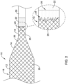
- FIG. 2 illustrates the proximal portion of an example balloon 10 bonded to a portion of catheter shaft 30.
- one of more filaments 20 of fiber braid 18 may extend in a proximal direction from the balloon body 12, along the proximal balloon cone 14 and further along the proximal balloon waist 15.
- FIG. 2 illustrates a bonding sleeve 22 disposed along the proximal portion of the proximal waist 15.
- bonding sleeve 22 may be designed to cover, encapsulate, embed and/or seal the proximal portion of the braid 18 located at the proximal portion of the proximal waist 15.
- the detailed view shown in FIG. 2 illustrates that a portion of bonding sleeve 22 may extend along a proximal portion of the proximal waist 15.
- the bonding sleeve 22 may be designed such that it extends in a proximal-to-distal direction along at least a portion the proximal waist 15.
- the detailed view of FIG. 2 shows that bonding sleeve 22 may extend over the end of the proximal waist 15 of balloon 10 (the end of the proximal waist 15 of balloon 10 is depicted as dashed line 25 in the detailed view of FIG. 2 ).
- bonding sleeve 22 may wick and/or flow in a distal-to-proximal direction along the fibers 20 of braid 18.
- a distal portion 24 of bonding sleeve 22 is depicted in both the detailed and non-detailed views of FIG. 2 . It can be appreciated the distal portion 24 of bonding sleeve 22 may or may not terminate a uniform distance from end of proximal waist 15.
- bonding sleeve 22 wicks and/or flows in a distal-to-proximal direction along the fibers 20 of braid 18, that some portions of bonding sleeve may advance further along the braid 18 than other adjacent portions (as depicted by the jagged line of distal portion 24 of bonding sleeve 22).
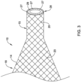
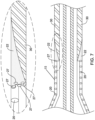
- FIG. 3 illustrates an example step in manufacturing catheter system 11.
- FIG. 3 shows that the proximal waist 15 may be trimmed to an appropriate length prior to bonding the proximal waist 15 of balloon 10 to catheter shaft 30.
- FIG. 3 illustrates that the proximal waist 15 of balloon 10 has been cleanly cut along proximal edge 28.
- FIG. 3 illustrates that the trimming process of proximal balloon waist 15 may reveal a proximal face 29 of the proximal waist 15.
- the proximal face 29 shows the ends 27 of one or more fibers 20 of braid 18.
- the ends 27 of fibers are positioned along the proximal face 29.
- the trimming process may result in the end 27 of the proximal balloon waist aligning with the ends 27 of the one or more fibers 20 of braid 18.
- the trimming process may result in one or more of fibers 20 becoming exposed along either the proximal face 29 and/or along the outer surface of proximal balloon waist 15. Further, the trimming process may cause the ends 27 of the one or more fibers 20 to become unraveled, frayed, exposed, released and/or unattached to the proximal waist 15 and/or proximal face 29. In some instances, the ends 27 of one or more fibers 20 may extend radially outward of the outer diameter of the proximal waist 15.
- the ends 27 of one or more fibers 20 may interfere with a medical devices and/or delivery systems utilized in conjunction with catheter system 11.
- the ends 27 of the one or more fibers 20 may interfere with a stent being positioned on balloon 10. Therefore, it may be desirable to recapture, cover, encase, encapsulate, overlay and/or seal the ends 27 of the one or more fibers 20 within another material.
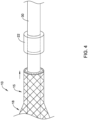
- FIG. 4 shows an example assembly step in manufacturing catheter system 11.
- FIG. 4 shows a bonding sleeve 22 (prior to being melted) being positioned on catheter shaft 30. Further, FIG. 4 shows catheter shaft 30 extending through the proximal waist 15. Additionally, FIG. 4 shows balloon 10 (including proximal waist 15) being advanced toward bonding sleeve 22. However, while FIG. 4 illustrates balloon 10 (including proximal waist 15) being advanced toward bonding sleeve 22, it is also contemplated that bonding sleeve 22 may be advanced toward proximal waist 15.
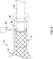
- FIG. 5 shows another example assembly step in manufacturing catheter system 11.
- FIG. 5 shows that bonding sleeve 22 and/or and proximal waist 15 have been moved to a position in which it abuts proximal waist 15 of balloon 10.
- FIG. 5 illustrates that a portion of the proximal face 29 (shown in FIG. 3 ) of proximal waist 15 may create a butt joint (e.g., a joint in which the proximal face of the proximal waist 15 may contact a distal face of the bonding sleeve 22) prior to the bonding process.
- a butt joint e.g., a joint in which the proximal face of the proximal waist 15 may contact a distal face of the bonding sleeve 22
- this is not intended to be limiting.
- Other arrangements of proximal waist 15, bonding sleeve 22 and catheter shaft 30 are contemplated.
- FIG. 6 shows another example assembly step in manufacturing catheter system 11.
- FIG. 6 shows an example process for melting bonding sleeve 22 such that it melts and/or reflows over the proximal end of the proximal waist 15.
- FIG. 6 illustrates a piece of heat shrink 36 positioned over the proximal waist 15, the bonding sleeve 22 and the catheter shaft 30. Additionally, FIG. 6 shows energy 38 (e.g., laser energy, thermal energy, etc.) being applied to the heat shrink 36.
- energy 38 e.g., laser energy, thermal energy, etc.
- the heat shrink 36 may transfer/disperse the energy to the bonding sleeve 22, proximal waist 15 and/or the catheter shaft 30, thereby thermally bonding the bonding sleeve 22 to the proximal waist 15 and/or the catheter shaft 30.
- the melting points of the balloon material, fibers 20, bonding sleeve 22, and catheter shaft may be the same or they may be different.
- the bonding sleeve 22 may be made from a material having a melting point which is lower than the balloon material, fibers 20 and/or bonding sleeve 22.
- all or a portion of balloon 10 (including proximal balloon waist 15) may be manufactured from Pebax ® , which has an approximate melt temperature of 220°C.
- All or a portion of catheter shaft 30 may be manufactured from Grilamid L20 ® , for example, which has an approximate melt temperature of 178°C.
- All or a portion of fibers 20 may include Vectran ® , for example, which has an approximate melt temp of 330°C and does not melt at bonding temps.
- the catheter system 11 illustrated and described with respect to FIG. 2 may be the configuration of the catheter system 11 after processing the catheter system as described in FIG. 6 .
- the illustration and description of the bonding sleeve and proximal waist interface in FIG. 2 may represent the catheter after it undergoes the processing and bonding steps as described in FIGS. 3-6 .
- FIG. 7 illustrates a cross-sectional view of the proximal waist 15, bonding sleeve 22 and catheter shaft 30 after the bonding step has been performed as described in FIG. 6 .
- FIG. 7 illustrates one or more ends 27 of fibers 20 being captured, covered, encased, encapsulated, overlaid and/or sealed by the material of bonding sleeve 22.
- FIG. 7 shows that after energy 38 is applied during the assembly step as described in FIG. 6 , the bonding sleeve 22 may melt and/or reflow into and around the ends 27 of fibers 20 of braid 18. It is noted that FIG. 7 does not show heat shrink 36 (shown in FIG.
- bonding sleeve 22 may melt and/or reflow into the proximal waist 15 which includes fibers 20 of fiber braid 18. It can be further appreciated the trimming of balloon 10 as described in FIG. 3 may results in cavities, channels, openings and/or spaces existing between fibers 20.
- the cavities, channels, openings and/or spaces may permit the bonding sleeve 22 material to wick up one or more fibers 20 of braid 18, thereby surrounding, covering, encasing, encapsulating, overlaid and/or sealing the fibers 20 within the bonding material 22.
- Balloon 10 may be pre-formed by radial expansion of a tubular parison, which is optionally also longitudinally stretched.
- the extruded parison may be radially expanded in a mold or by free-blowing.
- the parison may be pre-stretched longitudinally before expansion or reformed in various ways to reduce thickness of the balloon cone and waist regions prior to radial expansion.
- the blowing process may utilize pressurization under tension, followed by rapid dipping into a heated fluid; a sequential dipping with differing pressurization; a pulsed pressurization with compressible or incompressible fluid, after the material has been heated. Heating may also be accomplished by heating the pressurization fluid injected into the parison.
- Balloon 10 may be formed from balloon materials including compliant, semi-compliant, and non-compliant materials. These materials may include thermoplastic polymers, elastomers, and non-elastomers. Such materials may include low, linear low, medium, and high density polyethylenes, polypropylenes, and copolymers and terpolymers thereof; polyurethanes; polyesters and copolyesters; polycarbonates; polyamides; thermoplastic polyimides; polyetherimides; polyetheretherketones (PEEK) and PES (polyether sulfone); and copolymers and terpolymers thereof. Physical blends and copolymers of such materials may also be used.
- compliant, semi-compliant, and non-compliant materials may include thermoplastic polymers, elastomers, and non-elastomers. Such materials may include low, linear low, medium, and high density polyethylenes, polypropylenes, and copolymers and terpolymers thereof; polyurethanes; polyester
- polyesters include, but are not limited to, polyethylene terephthalate (PET), polyethylene naphthalate (PEN), polybutylene terephthalate, and copolymers thereof.
- PET polyethylene terephthalate
- PEN polyethylene naphthalate
- polybutylene terephthalate polybutylene terephthalate
- polyamides which may be used include nylon 6, nylon 64, nylon 66, nylon 610, nylon 610, nylon 612, nylon 46, nylon 9, nylon 10, nylon 11, nylon 12, and mixtures thereof.
- suitable polyurethanes include, but are not limited to, aromatic polyether-based thermoplastic polyurethanes (TPUs) such as those available under the tradename of Tecothane ® from Thermedics; thermoplastic polyurethane elastomer available under the tradename of Pellethane ® , such as Pellethane ® 2363-75D from Dow Chemical Co.; and high strength engineering thermoplastic polyurethane available under the tradename of Isoplast ® , such as Isoplast ® 301 and 302 available from Dow Chemical Co.
- TPUs aromatic polyether-based thermoplastic polyurethanes
- Tecothane ® from Thermedics
- Pellethane ® such as Pellethane ® 2363-75D from Dow Chemical Co.
- Isoplast ® such as Isoplast ® 301 and 302 available from Dow Chemical Co.
- the balloon 10 may be formed from poly (ether-block-amide) copolymers.
- the polyamide/polyether block copolymers are commonly identified by the acronym PEBA (polyether block amide).
- PEBA polyether block amide
- the polyamide and polyether segments of these block copolymers may be linked through amide linkages, or ester linked segmented polymers (e.g., polyamide/polyether polyesters).
- Such polyamide/polyether/polyester block copolymers are made by a molten state polycondensation reaction of a dicarboxylic polyamide and a polyether diol. The result is a short chain polyester made up of blocks of polyamide and polyether.
- Polymers of this type are commercially available under the tradename of Pebax ® from Arkema. Specific example are the "33" series polymers with hardness 60 and above, Shore D scale, for example, Pebax ® 6333, 7033, and 7233. These polymers are made up of nylon 12 segments and poly(tetramethylene ether) segments linked by ester groups.
- Polyester/polyether segmented block copolymers may also be employed herein. Such polymers are made up of at least two polyester and at least two polyether segments.
- the polyether segments are the same as previously described for the polyamide/polyether block copolymers useful in the disclosure.
- the polyester segments are polyesters of an aromatic dicarboxylic acid and a two to four carbon diol.
- the polyether segments of the polyester/polyether segmented block copolymers are aliphatic polyethers having at least 2 and no more than 10 linear saturated aliphatic carbon atoms between ether linkages.
- Ether segments may have 4-6 carbons between ether linkages, and can be poly(tetramethylene ether) segments.
- examples of other polyethers which may be employed in place of or in addition to tetramethylene ether segments include polyethylene glycol, polypropylene glycol, poly(pentamethylene ether) and poly(hexamethylene ether).
- the hydrocarbon portions of the polyether may be optionally branched.
- An example is the polyether of 2-ethylhexane diol. Generally such branches will contain no more than two carbon atoms.
- the molecular weight of the polyether segments is suitably between about 400 and 2,500, such as between 650 and 1000.
- the polyester segments of the polyester/polyether segmented block copolymers are polyesters of an aromatic dicarboxylic acid and a two to four carbon diol.
- Suitable dicarboxylic acids used to prepare the polyester segments of the polyester/polyether block copolymers are ortho-, meta-, or para-phthalic acid, napthalenedicarboxylic acid, or meta-terphenyl-4,4'-dicarboxylic acids.
- polyester/polyether block copolymers are poly(butylene terephthalate)-block-poly(tetramethylene oxide) polymers such as Arnitel ® EM 740, sold by DSM Engineering Plastics, and Hytrel ® polymers, sold by DuPont, such as Hytrel ® 8230.
- Balloon 10 may be capable of being inflated to relative high pressures.
- the balloon 10 may be inflated to pressures up to about 20 atm or more, or up to about 25 atm or more, or up to about 30 atm or more, or up to about 40 atm or more, or up to about 45 atm or more, or up to about 50 atm or more, or about 20-50 atm, or about 25-40 atm, or about 30-50 atm.
- the bond between the proximal waist portion 15 and the catheter shaft 30 (as well as the bond between the distal waist portion 17 and the catheter shaft 30) is maintained.
- the fluid tight bond between the fiber braid 18 and the balloon 10 is also maintained at these elevated pressures.
- the balloon 10 is formed from a compliant material.
- the balloon 10 is formed from an elastomer, such as a block copolymer elastomer.
- the block copolymer elastomer may be a poly(ether-block-amide) copolymer.
- the balloon can also be formed of layers, for example, an inner layer formed of a first polymer material and an outer layer formed from a second polymer material different than the first polymer material.
- the inner layer may be formed from an elastomeric polymer material, for example, a block copolymer elastomer, and the outer layer is formed from a non-elastomeric polymer material.
- the inner layer is formed of a poly(ether-block-amide) copolymer; and the outer layer is formed of a polyamide.
- the fiber braid 18 may be formed from a suitable polymer material.
- suitable fiber braid materials include, for example, polyesters, polyolefins, polyamides, polyurethanes, liquid crystal polymers, polyimides, and mixtures thereof. More specific examples include, but are not limited to, polyesters such as polyethylene terephthalate (PET), polybutylene terephthalate (PBT), and polytrimethylene terephthalate (PTT).
- PET polyethylene terephthalate
- PBT polybutylene terephthalate
- PTT polytrimethylene terephthalate
- Polyamides include nylons and aramids such as Kevlar ® .
- Liquid crystal polymers include Vectran ® .
- Polyolefins include ultrahigh molecular weight polyethylene, such as Dyneema ® sold by DSM Dyneema BVm Heerlen, Netherlands, Spectra ® fibers, sold by Honeywell, and very high density polyethylene, and polypropylene fibers. Elastomeric fibers can be used in some cases.
- the fiber braid 18 comprises an ultra high molecular weight polyethylene (UHMPE).
- UHMPEs include, but are not limited to, Dyneema ® fiber available from DSM Dyneema BVm Heerlen, Netherlands, Spectra ® fiber available from Honeywell in Morristown and Pegasus UHMWPE fiber available from Pegasus Materials in Shanghai, China.
- the UHMWPE fibers provide excellent strength and modulus with a small filament size to provide excellent balloon coverage and maintaining a minimal profile. However, when melted, the fibers lose their high molecular orientation and consequently, may also lose their bond tensile strength at the proximal waist portion 15 and/or the distal waist portion 17 of the balloon 10 at a thermal bond interface.
- coatings may be optionally applied to the balloon 10, such as between the outer surface of the balloon 10 and the fiber braid 18, over the outer surface of the fiber braid 18 or both.
- the coating includes a thermoplastic elastomer.
- the coating includes a thermoplastic polyurethane.
- the coating of a thermoplastic polyurethane may be applied to the balloon 10 using a suitable technique (e.g., dip coating, spray coating, rolling, or the like) prior to braiding and is also applied to the balloon/braid after braiding.
- the catheter shaft 30 and/or other parts of catheter system 11 may be formed from any suitable shaft material.
- suitable shaft material examples include, but are not limited to, polytetrafluoroethylene (PTFE), ethylene tetrafluoroethylene (ETFE), fluorinated ethylene propylene (FEP), polyoxymethylene (POM, for example, DELRIN ® available from DuPont), polyether block ester, polyurethane (for example, Polyurethane 85A), polypropylene (PP), polyvinylchloride (PVC), polyether-ester (for example, ARNITEL ® available from DSM Engineering Plastics), ether or ester based copolymers (for example, butylene/poly(alkylene ether) phthalate and/or other polyester elastomers such as HYTREL ® available from DuPont), polyamide (for example, DURETHAN ® available from Bayer or CRISTAMID ® available from Elf Atochem),
- the sheath can be blended with a liquid crystal polymer (LCP).
- LCP liquid crystal polymer
- the shaft material mixture can contain up to about 6 percent LCP.
- the catheter shaft 30 is formed from a polyamide, for example Grilamid ® which is commercially available from EMS-Grivory.
Landscapes
- Health & Medical Sciences (AREA)
- Heart & Thoracic Surgery (AREA)
- Life Sciences & Earth Sciences (AREA)
- Engineering & Computer Science (AREA)
- Biomedical Technology (AREA)
- General Health & Medical Sciences (AREA)
- Biophysics (AREA)
- Anesthesiology (AREA)
- Child & Adolescent Psychology (AREA)
- Hematology (AREA)
- Animal Behavior & Ethology (AREA)
- Pulmonology (AREA)
- Public Health (AREA)
- Veterinary Medicine (AREA)
- Manufacturing & Machinery (AREA)
- Mechanical Engineering (AREA)
- Materials For Medical Uses (AREA)
- Media Introduction/Drainage Providing Device (AREA)
Claims (14)
- Katheteranordnung, aufweisend:einen Katheterschaft (30);einen Ballon (10), der an dem Katheterschaft (30) angebracht ist, wobei der Ballon (10) einen Körper (12) und einen proximalen Taillenabschnitt (15) aufweist, wobei der proximale Taillenabschnitt (15) ein proximales Ende aufweist;ein Fasergeflecht (18) mit einem oder mehreren einzelnen Filamenten, die entlang des Ballons (10) angeordnet sind, wobei das Fasergeflecht (18) ein proximales Ende aufweist, das mit dem proximalen Ende des Taillenabschnitts (15) fluchtet; undeine Polymerhülse (22), die auf dem Katheterschaft (30) angeordnet ist, wobei die Polymerhülse (22) an dem proximalen Ende der Ballontaille und dem proximalen Ende des Geflechts (18) anliegt, wobeidie Polymerhülse (22) ein distales Ende aufweist und sich ein Abschnitt des distalen Endes der Polymerhülse (22) in das proximale Ende des Taillenabschnitts erstreckt.
- Katheteranordnung nach Anspruch 1, wobei die Polymerhülse (22) ein distales Ende aufweist und sich ein Abschnitt des distalen Endes der Polymerhülse (22) in das proximale Ende des Geflechts (18) erstreckt.
- Katheteranordnung nach Anspruch 1 oder 2, wobei ein oder mehrere Abschnitte der Polymerhülse (22) entlang eines oder mehrerer einzelner Filamente des Geflechts (18) innerhalb des Taillenbereichs gewickelt sind.
- Katheteranordnung nach einem der Ansprüche 1 bis 3, wobei die Polymerhülse (22) mit dem Taillenabschnitt thermisch verbunden ist.
- Katheteranordnung nach einem der Ansprüche 1 bis 4, wobei die Polymerhülse (22) mit dem Geflecht (18) thermisch verbunden ist.
- Katheteranordnung nach einem der Ansprüche 1 bis 5, wobei der Taillenabschnitt und die Polymerhülse (22) mit dem Katheterschaft (30) thermisch verbunden sind.
- Katheteranordnung nach einem der Ansprüche 1 bis 6, wobei die Ballontaille ein Polymer aufweist.
- Katheteranordnung nach Anspruch 7, wobei sich das Polymer der Ballontaille von dem Polymer unterscheidet, das die Polymerhülse (22) aufweist.
- Katheteranordnung nach Anspruch 7, wobei das Polymer der Ballontaille einen Schmelzpunkt aufweist, der höher als der Schmelzpunkt des Polymers der Polymerhülse (22) ist.
- Katheteranordnung nach Anspruch 7, wobei der Schmelzpunkt des Polymers der Ballontaille mit dem Schmelzpunkt des Polymers der Polymerhülse (22) übereinstimmt.
- Katheteranordnung nach einem der Ansprüche 1 bis 10, wobei das Fasergeflecht (18) ein Material mit einem Schmelzpunkt aufweist, der höher als der Schmelzpunkt der Taille (15) oder des Polymers der Polymerhülse (22) ist.
- Katheteranordnung nach einem der Ansprüche 1 bis 11, wobei die Polymerhülse (22) mit einem oder mehreren der Filamente (20) des Fasergeflechts (18) verbunden ist.
- Katheteranordnung nach einem der Ansprüche 1 bis 12, wobei sich ein oder mehrere Abschnitte der Polymerhülse (22) entlang der einzelnen Filamente des Geflechts (18) erstrecken.
- Verfahren zum Herstellen einer Katheteranordnung, wobei das Verfahren aufweist:Anordnen eines Fasergeflechts (18) um einen Ballon (10), wobei der Ballon (10) einen Taillenabschnitt und einen Körperabschnitt (12) aufweist, wobei der Taillenabschnitt und das Fasergeflecht (18) jeweils ein Ende (27) aufweisen, wobei das Ende (27) der Taille (15) mit dem Ende (27) des Geflechts (18) fluchtet;Anordnen des Ballons (10) auf einem Katheterschaft (30);Anordnen einer Polymerhülse (22) auf einem Katheterschaft (30), der an dem Ende (27) des Taillenabschnitts anliegt; undAufbringen von Wärme auf mindestens einen Abschnitt der Ballontaille und der Polymerhülse (22), um die Polymerhülse (22) mit der Ballontaille thermisch zu verbinden, wobei sich ein Abschnitt der Polymerhülse (22) in den Taillenabschnitt hinein erstreckt.
Applications Claiming Priority (2)
| Application Number | Priority Date | Filing Date | Title |
|---|---|---|---|
| US201662414325P | 2016-10-28 | 2016-10-28 | |
| PCT/US2017/057651 WO2018080926A1 (en) | 2016-10-28 | 2017-10-20 | Medical balloon with reinforcing member |
Publications (2)
| Publication Number | Publication Date |
|---|---|
| EP3532145A1 EP3532145A1 (de) | 2019-09-04 |
| EP3532145B1 true EP3532145B1 (de) | 2024-11-27 |
Family
ID=60263066
Family Applications (1)
| Application Number | Title | Priority Date | Filing Date |
|---|---|---|---|
| EP17794538.3A Active EP3532145B1 (de) | 2016-10-28 | 2017-10-20 | Medizinischer ballon mit verstärkungselement |
Country Status (5)
| Country | Link |
|---|---|
| US (2) | US10709877B2 (de) |
| EP (1) | EP3532145B1 (de) |
| JP (1) | JP2019533524A (de) |
| CN (1) | CN110139689B (de) |
| WO (1) | WO2018080926A1 (de) |
Families Citing this family (5)
| Publication number | Priority date | Publication date | Assignee | Title |
|---|---|---|---|---|
| US12447319B2 (en) | 2020-07-29 | 2025-10-21 | Neuravi Limited | Enhanced balloon bonding for balloon guide catheters while minimizing outer profiles |
| US20220031341A1 (en) | 2020-07-29 | 2022-02-03 | Neuravi Limited | Adhesive-Free Bonded Balloon for a Balloon Guide Catheter With Minimal Outer Profile |
| CN114939222A (zh) * | 2021-02-08 | 2022-08-26 | 赛诺神畅医疗科技有限公司 | 一种心脏瓣膜球囊扩张导管 |
| JP2025523731A (ja) * | 2022-07-29 | 2025-07-25 | バード・ペリフェラル・バスキュラー・インコーポレーテッド | 可変直径を有する膨張可能な医療用バルーン及び関連する方法 |
| WO2025137674A1 (en) * | 2023-12-21 | 2025-06-26 | Alpfa Medical, Inc. | Apparatus for pulsed field ablation applications with superelastic materials |
Family Cites Families (11)
| Publication number | Priority date | Publication date | Assignee | Title |
|---|---|---|---|---|
| US5195969A (en) * | 1991-04-26 | 1993-03-23 | Boston Scientific Corporation | Co-extruded medical balloons and catheter using such balloons |
| US5868779A (en) | 1997-08-15 | 1999-02-09 | Ruiz; Carlos E. | Apparatus and methods for dilating vessels and hollow-body organs |
| US6923787B2 (en) | 2001-12-20 | 2005-08-02 | Scimed Life Systems, Inc. | Catheter having an improved balloon-to-catheter bond |
| US20030135231A1 (en) * | 2002-01-17 | 2003-07-17 | Goodin Richardf L. | Catheter bond configuration |
| US7147619B2 (en) * | 2002-07-22 | 2006-12-12 | Advanced Cardiovascular Systems, Inc. | Catheter balloon having impregnated balloon skirt sections |
| US8500797B2 (en) | 2004-09-08 | 2013-08-06 | Boston Scientific Scimed, Inc. | Medical devices |
| US20060182907A1 (en) * | 2005-02-11 | 2006-08-17 | Boston Scientific Scimed, Inc. | Novel microfibrillar reinforced polymer-polymer composites for use in medical devices |
| US8672990B2 (en) * | 2005-05-27 | 2014-03-18 | Boston Scientific Scimed, Inc. | Fiber mesh controlled expansion balloon catheter |
| JP4948089B2 (ja) | 2006-08-25 | 2012-06-06 | キヤノン株式会社 | 撮像装置及びその制御方法 |
| US20120277783A1 (en) * | 2011-04-28 | 2012-11-01 | Medtronic Vascular, Inc. | Reinforced Dilatation Balloon and Methods |
| EP3377165B1 (de) * | 2015-11-20 | 2022-12-28 | Boston Scientific Scimed, Inc. | Ballonkatheter |
-
2017
- 2017-10-20 CN CN201780081180.2A patent/CN110139689B/zh active Active
- 2017-10-20 WO PCT/US2017/057651 patent/WO2018080926A1/en not_active Ceased
- 2017-10-20 JP JP2019522688A patent/JP2019533524A/ja active Pending
- 2017-10-20 EP EP17794538.3A patent/EP3532145B1/de active Active
- 2017-10-20 US US15/789,324 patent/US10709877B2/en active Active
-
2020
- 2020-06-09 US US16/897,026 patent/US11511088B2/en active Active
Also Published As
| Publication number | Publication date |
|---|---|
| JP2019533524A (ja) | 2019-11-21 |
| US10709877B2 (en) | 2020-07-14 |
| WO2018080926A1 (en) | 2018-05-03 |
| US11511088B2 (en) | 2022-11-29 |
| US20180117287A1 (en) | 2018-05-03 |
| CN110139689A (zh) | 2019-08-16 |
| CN110139689B (zh) | 2022-03-08 |
| US20200297981A1 (en) | 2020-09-24 |
| EP3532145A1 (de) | 2019-09-04 |
Similar Documents
| Publication | Publication Date | Title |
|---|---|---|
| US11511088B2 (en) | Medical balloon with reinforcing member | |
| US20250242137A1 (en) | Medical balloon | |
| US12324884B2 (en) | Balloon catheter | |
| EP2015819B1 (de) | Herstellungsverfahren für einen katheter | |
| US20170354802A1 (en) | Medical balloon | |
| EP3615099B1 (de) | Medizinischer ballon | |
| US10780251B2 (en) | Expandable medical devices | |
| US10849629B2 (en) | Medical balloon | |
| US12471949B2 (en) | Reinforced medical balloon |
Legal Events
| Date | Code | Title | Description |
|---|---|---|---|
| STAA | Information on the status of an ep patent application or granted ep patent |
Free format text: STATUS: UNKNOWN |
|
| STAA | Information on the status of an ep patent application or granted ep patent |
Free format text: STATUS: THE INTERNATIONAL PUBLICATION HAS BEEN MADE |
|
| PUAI | Public reference made under article 153(3) epc to a published international application that has entered the european phase |
Free format text: ORIGINAL CODE: 0009012 |
|
| STAA | Information on the status of an ep patent application or granted ep patent |
Free format text: STATUS: REQUEST FOR EXAMINATION WAS MADE |
|
| 17P | Request for examination filed |
Effective date: 20190528 |
|
| AK | Designated contracting states |
Kind code of ref document: A1 Designated state(s): AL AT BE BG CH CY CZ DE DK EE ES FI FR GB GR HR HU IE IS IT LI LT LU LV MC MK MT NL NO PL PT RO RS SE SI SK SM TR |
|
| AX | Request for extension of the european patent |
Extension state: BA ME |
|
| DAV | Request for validation of the european patent (deleted) | ||
| DAX | Request for extension of the european patent (deleted) | ||
| STAA | Information on the status of an ep patent application or granted ep patent |
Free format text: STATUS: EXAMINATION IS IN PROGRESS |
|
| 17Q | First examination report despatched |
Effective date: 20230602 |
|
| GRAP | Despatch of communication of intention to grant a patent |
Free format text: ORIGINAL CODE: EPIDOSNIGR1 |
|
| STAA | Information on the status of an ep patent application or granted ep patent |
Free format text: STATUS: GRANT OF PATENT IS INTENDED |
|
| INTG | Intention to grant announced |
Effective date: 20240528 |
|
| GRAS | Grant fee paid |
Free format text: ORIGINAL CODE: EPIDOSNIGR3 |
|
| GRAA | (expected) grant |
Free format text: ORIGINAL CODE: 0009210 |
|
| STAA | Information on the status of an ep patent application or granted ep patent |
Free format text: STATUS: THE PATENT HAS BEEN GRANTED |
|
| AK | Designated contracting states |
Kind code of ref document: B1 Designated state(s): AL AT BE BG CH CY CZ DE DK EE ES FI FR GB GR HR HU IE IS IT LI LT LU LV MC MK MT NL NO PL PT RO RS SE SI SK SM TR |
|
| REG | Reference to a national code |
Ref country code: GB Ref legal event code: FG4D |
|
| REG | Reference to a national code |
Ref country code: CH Ref legal event code: EP |
|
| REG | Reference to a national code |
Ref country code: DE Ref legal event code: R096 Ref document number: 602017086408 Country of ref document: DE |
|
| REG | Reference to a national code |
Ref country code: IE Ref legal event code: FG4D |
|
| REG | Reference to a national code |
Ref country code: NL Ref legal event code: FP |
|
| REG | Reference to a national code |
Ref country code: LT Ref legal event code: MG9D |
|
| PG25 | Lapsed in a contracting state [announced via postgrant information from national office to epo] |
Ref country code: PT Free format text: LAPSE BECAUSE OF FAILURE TO SUBMIT A TRANSLATION OF THE DESCRIPTION OR TO PAY THE FEE WITHIN THE PRESCRIBED TIME-LIMIT Effective date: 20250327 Ref country code: IS Free format text: LAPSE BECAUSE OF FAILURE TO SUBMIT A TRANSLATION OF THE DESCRIPTION OR TO PAY THE FEE WITHIN THE PRESCRIBED TIME-LIMIT Effective date: 20250327 Ref country code: HR Free format text: LAPSE BECAUSE OF FAILURE TO SUBMIT A TRANSLATION OF THE DESCRIPTION OR TO PAY THE FEE WITHIN THE PRESCRIBED TIME-LIMIT Effective date: 20241127 |
|
| PG25 | Lapsed in a contracting state [announced via postgrant information from national office to epo] |
Ref country code: FI Free format text: LAPSE BECAUSE OF FAILURE TO SUBMIT A TRANSLATION OF THE DESCRIPTION OR TO PAY THE FEE WITHIN THE PRESCRIBED TIME-LIMIT Effective date: 20241127 |
|
| REG | Reference to a national code |
Ref country code: AT Ref legal event code: MK05 Ref document number: 1745146 Country of ref document: AT Kind code of ref document: T Effective date: 20241127 |
|
| PG25 | Lapsed in a contracting state [announced via postgrant information from national office to epo] |
Ref country code: BG Free format text: LAPSE BECAUSE OF FAILURE TO SUBMIT A TRANSLATION OF THE DESCRIPTION OR TO PAY THE FEE WITHIN THE PRESCRIBED TIME-LIMIT Effective date: 20241127 |
|
| PG25 | Lapsed in a contracting state [announced via postgrant information from national office to epo] |
Ref country code: ES Free format text: LAPSE BECAUSE OF FAILURE TO SUBMIT A TRANSLATION OF THE DESCRIPTION OR TO PAY THE FEE WITHIN THE PRESCRIBED TIME-LIMIT Effective date: 20241127 |
|
| PG25 | Lapsed in a contracting state [announced via postgrant information from national office to epo] |
Ref country code: NO Free format text: LAPSE BECAUSE OF FAILURE TO SUBMIT A TRANSLATION OF THE DESCRIPTION OR TO PAY THE FEE WITHIN THE PRESCRIBED TIME-LIMIT Effective date: 20250227 |
|
| PG25 | Lapsed in a contracting state [announced via postgrant information from national office to epo] |
Ref country code: LV Free format text: LAPSE BECAUSE OF FAILURE TO SUBMIT A TRANSLATION OF THE DESCRIPTION OR TO PAY THE FEE WITHIN THE PRESCRIBED TIME-LIMIT Effective date: 20241127 Ref country code: GR Free format text: LAPSE BECAUSE OF FAILURE TO SUBMIT A TRANSLATION OF THE DESCRIPTION OR TO PAY THE FEE WITHIN THE PRESCRIBED TIME-LIMIT Effective date: 20250228 Ref country code: AT Free format text: LAPSE BECAUSE OF FAILURE TO SUBMIT A TRANSLATION OF THE DESCRIPTION OR TO PAY THE FEE WITHIN THE PRESCRIBED TIME-LIMIT Effective date: 20241127 |
|
| PG25 | Lapsed in a contracting state [announced via postgrant information from national office to epo] |
Ref country code: PL Free format text: LAPSE BECAUSE OF FAILURE TO SUBMIT A TRANSLATION OF THE DESCRIPTION OR TO PAY THE FEE WITHIN THE PRESCRIBED TIME-LIMIT Effective date: 20241127 |
|
| PG25 | Lapsed in a contracting state [announced via postgrant information from national office to epo] |
Ref country code: RS Free format text: LAPSE BECAUSE OF FAILURE TO SUBMIT A TRANSLATION OF THE DESCRIPTION OR TO PAY THE FEE WITHIN THE PRESCRIBED TIME-LIMIT Effective date: 20250227 |
|
| PG25 | Lapsed in a contracting state [announced via postgrant information from national office to epo] |
Ref country code: SM Free format text: LAPSE BECAUSE OF FAILURE TO SUBMIT A TRANSLATION OF THE DESCRIPTION OR TO PAY THE FEE WITHIN THE PRESCRIBED TIME-LIMIT Effective date: 20241127 |
|
| PG25 | Lapsed in a contracting state [announced via postgrant information from national office to epo] |
Ref country code: DK Free format text: LAPSE BECAUSE OF FAILURE TO SUBMIT A TRANSLATION OF THE DESCRIPTION OR TO PAY THE FEE WITHIN THE PRESCRIBED TIME-LIMIT Effective date: 20241127 |
|
| PG25 | Lapsed in a contracting state [announced via postgrant information from national office to epo] |
Ref country code: EE Free format text: LAPSE BECAUSE OF FAILURE TO SUBMIT A TRANSLATION OF THE DESCRIPTION OR TO PAY THE FEE WITHIN THE PRESCRIBED TIME-LIMIT Effective date: 20241127 |
|
| PG25 | Lapsed in a contracting state [announced via postgrant information from national office to epo] |
Ref country code: RO Free format text: LAPSE BECAUSE OF FAILURE TO SUBMIT A TRANSLATION OF THE DESCRIPTION OR TO PAY THE FEE WITHIN THE PRESCRIBED TIME-LIMIT Effective date: 20241127 |
|
| PG25 | Lapsed in a contracting state [announced via postgrant information from national office to epo] |
Ref country code: SK Free format text: LAPSE BECAUSE OF FAILURE TO SUBMIT A TRANSLATION OF THE DESCRIPTION OR TO PAY THE FEE WITHIN THE PRESCRIBED TIME-LIMIT Effective date: 20241127 |
|
| PG25 | Lapsed in a contracting state [announced via postgrant information from national office to epo] |
Ref country code: CZ Free format text: LAPSE BECAUSE OF FAILURE TO SUBMIT A TRANSLATION OF THE DESCRIPTION OR TO PAY THE FEE WITHIN THE PRESCRIBED TIME-LIMIT Effective date: 20241127 |
|
| PG25 | Lapsed in a contracting state [announced via postgrant information from national office to epo] |
Ref country code: IT Free format text: LAPSE BECAUSE OF FAILURE TO SUBMIT A TRANSLATION OF THE DESCRIPTION OR TO PAY THE FEE WITHIN THE PRESCRIBED TIME-LIMIT Effective date: 20241127 |
|
| REG | Reference to a national code |
Ref country code: DE Ref legal event code: R097 Ref document number: 602017086408 Country of ref document: DE |
|
| PG25 | Lapsed in a contracting state [announced via postgrant information from national office to epo] |
Ref country code: SE Free format text: LAPSE BECAUSE OF FAILURE TO SUBMIT A TRANSLATION OF THE DESCRIPTION OR TO PAY THE FEE WITHIN THE PRESCRIBED TIME-LIMIT Effective date: 20241127 |
|
| PLBE | No opposition filed within time limit |
Free format text: ORIGINAL CODE: 0009261 |
|
| STAA | Information on the status of an ep patent application or granted ep patent |
Free format text: STATUS: NO OPPOSITION FILED WITHIN TIME LIMIT |
|
| 26N | No opposition filed |
Effective date: 20250828 |