EP3532140B1 - Multi-lumen indwelling catheter - Google Patents
Multi-lumen indwelling catheter Download PDFInfo
- Publication number
- EP3532140B1 EP3532140B1 EP17794502.9A EP17794502A EP3532140B1 EP 3532140 B1 EP3532140 B1 EP 3532140B1 EP 17794502 A EP17794502 A EP 17794502A EP 3532140 B1 EP3532140 B1 EP 3532140B1
- Authority
- EP
- European Patent Office
- Prior art keywords
- lumen
- catheter
- distal
- length
- tube portion
- Prior art date
- Legal status (The legal status is an assumption and is not a legal conclusion. Google has not performed a legal analysis and makes no representation as to the accuracy of the status listed.)
- Active
Links
- 238000002347 injection Methods 0.000 claims description 44
- 239000007924 injection Substances 0.000 claims description 44
- 238000000034 method Methods 0.000 claims description 16
- 238000012279 drainage procedure Methods 0.000 claims description 8
- 230000007423 decrease Effects 0.000 claims description 6
- 239000003814 drug Substances 0.000 description 54
- 229940079593 drug Drugs 0.000 description 51
- 239000012530 fluid Substances 0.000 description 31
- 230000009977 dual effect Effects 0.000 description 24
- 230000006870 function Effects 0.000 description 13
- 239000000126 substance Substances 0.000 description 12
- 239000000463 material Substances 0.000 description 11
- 238000009826 distribution Methods 0.000 description 10
- 210000001519 tissue Anatomy 0.000 description 8
- 206010028980 Neoplasm Diseases 0.000 description 7
- 210000000056 organ Anatomy 0.000 description 7
- 238000011282 treatment Methods 0.000 description 7
- 210000003281 pleural cavity Anatomy 0.000 description 6
- 201000011510 cancer Diseases 0.000 description 5
- 229940044683 chemotherapy drug Drugs 0.000 description 4
- 210000003200 peritoneal cavity Anatomy 0.000 description 4
- 238000007789 sealing Methods 0.000 description 4
- 210000003932 urinary bladder Anatomy 0.000 description 4
- 239000003795 chemical substances by application Substances 0.000 description 3
- KRKNYBCHXYNGOX-UHFFFAOYSA-N citric acid Chemical compound OC(=O)CC(O)(C(O)=O)CC(O)=O KRKNYBCHXYNGOX-UHFFFAOYSA-N 0.000 description 3
- 238000000502 dialysis Methods 0.000 description 3
- 238000004519 manufacturing process Methods 0.000 description 3
- 238000002483 medication Methods 0.000 description 3
- 229920001296 polysiloxane Polymers 0.000 description 3
- 230000008569 process Effects 0.000 description 3
- 238000001356 surgical procedure Methods 0.000 description 3
- 208000034189 Sclerosis Diseases 0.000 description 2
- UIIMBOGNXHQVGW-UHFFFAOYSA-M Sodium bicarbonate Chemical compound [Na+].OC([O-])=O UIIMBOGNXHQVGW-UHFFFAOYSA-M 0.000 description 2
- 239000000853 adhesive Substances 0.000 description 2
- 230000001070 adhesive effect Effects 0.000 description 2
- 230000003115 biocidal effect Effects 0.000 description 2
- 238000002512 chemotherapy Methods 0.000 description 2
- 239000012829 chemotherapy agent Substances 0.000 description 2
- 238000004891 communication Methods 0.000 description 2
- 230000003247 decreasing effect Effects 0.000 description 2
- 230000000694 effects Effects 0.000 description 2
- 238000005516 engineering process Methods 0.000 description 2
- 238000011463 hyperthermic intraperitoneal chemotherapy Methods 0.000 description 2
- 238000009169 immunotherapy Methods 0.000 description 2
- 230000001939 inductive effect Effects 0.000 description 2
- 238000002955 isolation Methods 0.000 description 2
- 239000007788 liquid Substances 0.000 description 2
- 210000004072 lung Anatomy 0.000 description 2
- 239000000203 mixture Substances 0.000 description 2
- 230000037368 penetrate the skin Effects 0.000 description 2
- SQGYOTSLMSWVJD-UHFFFAOYSA-N silver(1+) nitrate Chemical compound [Ag+].[O-]N(=O)=O SQGYOTSLMSWVJD-UHFFFAOYSA-N 0.000 description 2
- 238000012800 visualization Methods 0.000 description 2
- 201000004384 Alopecia Diseases 0.000 description 1
- 108010006654 Bleomycin Proteins 0.000 description 1
- 206010027458 Metastases to lung Diseases 0.000 description 1
- 206010028813 Nausea Diseases 0.000 description 1
- 208000002151 Pleural effusion Diseases 0.000 description 1
- FAPWRFPIFSIZLT-UHFFFAOYSA-M Sodium chloride Chemical compound [Na+].[Cl-] FAPWRFPIFSIZLT-UHFFFAOYSA-M 0.000 description 1
- 102000003978 Tissue Plasminogen Activator Human genes 0.000 description 1
- 108090000373 Tissue Plasminogen Activator Proteins 0.000 description 1
- 229910052788 barium Inorganic materials 0.000 description 1
- DSAJWYNOEDNPEQ-UHFFFAOYSA-N barium atom Chemical compound [Ba] DSAJWYNOEDNPEQ-UHFFFAOYSA-N 0.000 description 1
- 230000004888 barrier function Effects 0.000 description 1
- 230000037365 barrier function of the epidermis Effects 0.000 description 1
- 239000000560 biocompatible material Substances 0.000 description 1
- 239000003124 biologic agent Substances 0.000 description 1
- 230000015572 biosynthetic process Effects 0.000 description 1
- 238000001815 biotherapy Methods 0.000 description 1
- 229960001561 bleomycin Drugs 0.000 description 1
- OYVAGSVQBOHSSS-UAPAGMARSA-O bleomycin A2 Chemical compound N([C@H](C(=O)N[C@H](C)[C@@H](O)[C@H](C)C(=O)N[C@@H]([C@H](O)C)C(=O)NCCC=1SC=C(N=1)C=1SC=C(N=1)C(=O)NCCC[S+](C)C)[C@@H](O[C@H]1[C@H]([C@@H](O)[C@H](O)[C@H](CO)O1)O[C@@H]1[C@H]([C@@H](OC(N)=O)[C@H](O)[C@@H](CO)O1)O)C=1N=CNC=1)C(=O)C1=NC([C@H](CC(N)=O)NC[C@H](N)C(N)=O)=NC(N)=C1C OYVAGSVQBOHSSS-UAPAGMARSA-O 0.000 description 1
- 239000008280 blood Substances 0.000 description 1
- 210000004369 blood Anatomy 0.000 description 1
- 239000010839 body fluid Substances 0.000 description 1
- 210000001124 body fluid Anatomy 0.000 description 1
- 239000002775 capsule Substances 0.000 description 1
- 150000001875 compounds Chemical class 0.000 description 1
- 238000002591 computed tomography Methods 0.000 description 1
- 238000005520 cutting process Methods 0.000 description 1
- 230000001419 dependent effect Effects 0.000 description 1
- 239000006185 dispersion Substances 0.000 description 1
- 238000001647 drug administration Methods 0.000 description 1
- 238000001914 filtration Methods 0.000 description 1
- 230000009969 flowable effect Effects 0.000 description 1
- 238000002594 fluoroscopy Methods 0.000 description 1
- 239000000499 gel Substances 0.000 description 1
- 238000001415 gene therapy Methods 0.000 description 1
- 230000005484 gravity Effects 0.000 description 1
- 208000024963 hair loss Diseases 0.000 description 1
- 230000003676 hair loss Effects 0.000 description 1
- 239000000017 hydrogel Substances 0.000 description 1
- 210000000987 immune system Anatomy 0.000 description 1
- 208000015181 infectious disease Diseases 0.000 description 1
- 238000009434 installation Methods 0.000 description 1
- 238000007912 intraperitoneal administration Methods 0.000 description 1
- 238000001990 intravenous administration Methods 0.000 description 1
- 238000012977 invasive surgical procedure Methods 0.000 description 1
- 230000007794 irritation Effects 0.000 description 1
- 230000007774 longterm Effects 0.000 description 1
- 238000002595 magnetic resonance imaging Methods 0.000 description 1
- 230000003211 malignant effect Effects 0.000 description 1
- 208000006178 malignant mesothelioma Diseases 0.000 description 1
- 239000003550 marker Substances 0.000 description 1
- 210000004379 membrane Anatomy 0.000 description 1
- 239000012528 membrane Substances 0.000 description 1
- 150000002736 metal compounds Chemical class 0.000 description 1
- 230000000813 microbial effect Effects 0.000 description 1
- 230000005012 migration Effects 0.000 description 1
- 238000013508 migration Methods 0.000 description 1
- 230000008693 nausea Effects 0.000 description 1
- HLXZNVUGXRDIFK-UHFFFAOYSA-N nickel titanium Chemical compound [Ti].[Ti].[Ti].[Ti].[Ti].[Ti].[Ti].[Ti].[Ti].[Ti].[Ti].[Ni].[Ni].[Ni].[Ni].[Ni].[Ni].[Ni].[Ni].[Ni].[Ni].[Ni].[Ni].[Ni].[Ni] HLXZNVUGXRDIFK-UHFFFAOYSA-N 0.000 description 1
- 229910001000 nickel titanium Inorganic materials 0.000 description 1
- 239000006072 paste Substances 0.000 description 1
- 239000005020 polyethylene terephthalate Substances 0.000 description 1
- 230000001737 promoting effect Effects 0.000 description 1
- 208000005069 pulmonary fibrosis Diseases 0.000 description 1
- 230000002784 sclerotic effect Effects 0.000 description 1
- 229910001961 silver nitrate Inorganic materials 0.000 description 1
- 229910000030 sodium bicarbonate Inorganic materials 0.000 description 1
- 235000017557 sodium bicarbonate Nutrition 0.000 description 1
- 239000011780 sodium chloride Substances 0.000 description 1
- 239000007787 solid Substances 0.000 description 1
- 239000000243 solution Substances 0.000 description 1
- 230000007480 spreading Effects 0.000 description 1
- 238000003892 spreading Methods 0.000 description 1
- 239000000725 suspension Substances 0.000 description 1
- 230000001360 synchronised effect Effects 0.000 description 1
- 239000000454 talc Substances 0.000 description 1
- 229910052623 talc Inorganic materials 0.000 description 1
- 230000001225 therapeutic effect Effects 0.000 description 1
- 238000002560 therapeutic procedure Methods 0.000 description 1
- 229960000187 tissue plasminogen activator Drugs 0.000 description 1
- 231100000331 toxic Toxicity 0.000 description 1
- 230000002588 toxic effect Effects 0.000 description 1
- 238000002604 ultrasonography Methods 0.000 description 1
- 230000000007 visual effect Effects 0.000 description 1
Images


Classifications
-
- A—HUMAN NECESSITIES
- A61—MEDICAL OR VETERINARY SCIENCE; HYGIENE
- A61M—DEVICES FOR INTRODUCING MEDIA INTO, OR ONTO, THE BODY; DEVICES FOR TRANSDUCING BODY MEDIA OR FOR TAKING MEDIA FROM THE BODY; DEVICES FOR PRODUCING OR ENDING SLEEP OR STUPOR
- A61M1/00—Suction or pumping devices for medical purposes; Devices for carrying-off, for treatment of, or for carrying-over, body-liquids; Drainage systems
- A61M1/14—Dialysis systems; Artificial kidneys; Blood oxygenators ; Reciprocating systems for treatment of body fluids, e.g. single needle systems for hemofiltration or pheresis
- A61M1/28—Peritoneal dialysis ; Other peritoneal treatment, e.g. oxygenation
- A61M1/285—Catheters therefor
-
- A—HUMAN NECESSITIES
- A61—MEDICAL OR VETERINARY SCIENCE; HYGIENE
- A61M—DEVICES FOR INTRODUCING MEDIA INTO, OR ONTO, THE BODY; DEVICES FOR TRANSDUCING BODY MEDIA OR FOR TAKING MEDIA FROM THE BODY; DEVICES FOR PRODUCING OR ENDING SLEEP OR STUPOR
- A61M25/00—Catheters; Hollow probes
- A61M25/0017—Catheters; Hollow probes specially adapted for long-term hygiene care, e.g. urethral or indwelling catheters to prevent infections
-
- A—HUMAN NECESSITIES
- A61—MEDICAL OR VETERINARY SCIENCE; HYGIENE
- A61M—DEVICES FOR INTRODUCING MEDIA INTO, OR ONTO, THE BODY; DEVICES FOR TRANSDUCING BODY MEDIA OR FOR TAKING MEDIA FROM THE BODY; DEVICES FOR PRODUCING OR ENDING SLEEP OR STUPOR
- A61M25/00—Catheters; Hollow probes
- A61M25/0021—Catheters; Hollow probes characterised by the form of the tubing
- A61M25/0023—Catheters; Hollow probes characterised by the form of the tubing by the form of the lumen, e.g. cross-section, variable diameter
- A61M25/0026—Multi-lumen catheters with stationary elements
- A61M25/003—Multi-lumen catheters with stationary elements characterized by features relating to least one lumen located at the distal part of the catheter, e.g. filters, plugs or valves
-
- A—HUMAN NECESSITIES
- A61—MEDICAL OR VETERINARY SCIENCE; HYGIENE
- A61M—DEVICES FOR INTRODUCING MEDIA INTO, OR ONTO, THE BODY; DEVICES FOR TRANSDUCING BODY MEDIA OR FOR TAKING MEDIA FROM THE BODY; DEVICES FOR PRODUCING OR ENDING SLEEP OR STUPOR
- A61M25/00—Catheters; Hollow probes
- A61M25/0043—Catheters; Hollow probes characterised by structural features
-
- A—HUMAN NECESSITIES
- A61—MEDICAL OR VETERINARY SCIENCE; HYGIENE
- A61M—DEVICES FOR INTRODUCING MEDIA INTO, OR ONTO, THE BODY; DEVICES FOR TRANSDUCING BODY MEDIA OR FOR TAKING MEDIA FROM THE BODY; DEVICES FOR PRODUCING OR ENDING SLEEP OR STUPOR
- A61M25/00—Catheters; Hollow probes
- A61M25/0067—Catheters; Hollow probes characterised by the distal end, e.g. tips
- A61M25/0068—Static characteristics of the catheter tip, e.g. shape, atraumatic tip, curved tip or tip structure
- A61M25/0071—Multiple separate lumens
-
- A—HUMAN NECESSITIES
- A61—MEDICAL OR VETERINARY SCIENCE; HYGIENE
- A61M—DEVICES FOR INTRODUCING MEDIA INTO, OR ONTO, THE BODY; DEVICES FOR TRANSDUCING BODY MEDIA OR FOR TAKING MEDIA FROM THE BODY; DEVICES FOR PRODUCING OR ENDING SLEEP OR STUPOR
- A61M25/00—Catheters; Hollow probes
- A61M25/0067—Catheters; Hollow probes characterised by the distal end, e.g. tips
- A61M25/0074—Dynamic characteristics of the catheter tip, e.g. openable, closable, expandable or deformable
- A61M25/0075—Valve means
-
- A—HUMAN NECESSITIES
- A61—MEDICAL OR VETERINARY SCIENCE; HYGIENE
- A61M—DEVICES FOR INTRODUCING MEDIA INTO, OR ONTO, THE BODY; DEVICES FOR TRANSDUCING BODY MEDIA OR FOR TAKING MEDIA FROM THE BODY; DEVICES FOR PRODUCING OR ENDING SLEEP OR STUPOR
- A61M31/00—Devices for introducing or retaining media, e.g. remedies, in cavities of the body
-
- A—HUMAN NECESSITIES
- A61—MEDICAL OR VETERINARY SCIENCE; HYGIENE
- A61M—DEVICES FOR INTRODUCING MEDIA INTO, OR ONTO, THE BODY; DEVICES FOR TRANSDUCING BODY MEDIA OR FOR TAKING MEDIA FROM THE BODY; DEVICES FOR PRODUCING OR ENDING SLEEP OR STUPOR
- A61M25/00—Catheters; Hollow probes
- A61M25/0021—Catheters; Hollow probes characterised by the form of the tubing
- A61M25/0023—Catheters; Hollow probes characterised by the form of the tubing by the form of the lumen, e.g. cross-section, variable diameter
- A61M25/0026—Multi-lumen catheters with stationary elements
- A61M25/003—Multi-lumen catheters with stationary elements characterized by features relating to least one lumen located at the distal part of the catheter, e.g. filters, plugs or valves
- A61M2025/0031—Multi-lumen catheters with stationary elements characterized by features relating to least one lumen located at the distal part of the catheter, e.g. filters, plugs or valves characterized by lumina for withdrawing or delivering, i.e. used for extracorporeal circuit treatment
-
- A—HUMAN NECESSITIES
- A61—MEDICAL OR VETERINARY SCIENCE; HYGIENE
- A61M—DEVICES FOR INTRODUCING MEDIA INTO, OR ONTO, THE BODY; DEVICES FOR TRANSDUCING BODY MEDIA OR FOR TAKING MEDIA FROM THE BODY; DEVICES FOR PRODUCING OR ENDING SLEEP OR STUPOR
- A61M25/00—Catheters; Hollow probes
- A61M25/0021—Catheters; Hollow probes characterised by the form of the tubing
- A61M25/0023—Catheters; Hollow probes characterised by the form of the tubing by the form of the lumen, e.g. cross-section, variable diameter
- A61M25/0026—Multi-lumen catheters with stationary elements
- A61M2025/0037—Multi-lumen catheters with stationary elements characterized by lumina being arranged side-by-side
-
- A—HUMAN NECESSITIES
- A61—MEDICAL OR VETERINARY SCIENCE; HYGIENE
- A61M—DEVICES FOR INTRODUCING MEDIA INTO, OR ONTO, THE BODY; DEVICES FOR TRANSDUCING BODY MEDIA OR FOR TAKING MEDIA FROM THE BODY; DEVICES FOR PRODUCING OR ENDING SLEEP OR STUPOR
- A61M25/00—Catheters; Hollow probes
- A61M25/0067—Catheters; Hollow probes characterised by the distal end, e.g. tips
- A61M25/0068—Static characteristics of the catheter tip, e.g. shape, atraumatic tip, curved tip or tip structure
- A61M2025/0073—Tip designed for influencing the flow or the flow velocity of the fluid, e.g. inserts for twisted or vortex flow
-
- A—HUMAN NECESSITIES
- A61—MEDICAL OR VETERINARY SCIENCE; HYGIENE
- A61M—DEVICES FOR INTRODUCING MEDIA INTO, OR ONTO, THE BODY; DEVICES FOR TRANSDUCING BODY MEDIA OR FOR TAKING MEDIA FROM THE BODY; DEVICES FOR PRODUCING OR ENDING SLEEP OR STUPOR
- A61M25/00—Catheters; Hollow probes
- A61M25/01—Introducing, guiding, advancing, emplacing or holding catheters
- A61M25/02—Holding devices, e.g. on the body
- A61M2025/0293—Catheter, guide wire or the like with means for holding, centering, anchoring or frictionally engaging the device within an artificial lumen, e.g. tube
-
- A—HUMAN NECESSITIES
- A61—MEDICAL OR VETERINARY SCIENCE; HYGIENE
- A61M—DEVICES FOR INTRODUCING MEDIA INTO, OR ONTO, THE BODY; DEVICES FOR TRANSDUCING BODY MEDIA OR FOR TAKING MEDIA FROM THE BODY; DEVICES FOR PRODUCING OR ENDING SLEEP OR STUPOR
- A61M2205/00—General characteristics of the apparatus
- A61M2205/33—Controlling, regulating or measuring
- A61M2205/3331—Pressure; Flow
-
- A—HUMAN NECESSITIES
- A61—MEDICAL OR VETERINARY SCIENCE; HYGIENE
- A61M—DEVICES FOR INTRODUCING MEDIA INTO, OR ONTO, THE BODY; DEVICES FOR TRANSDUCING BODY MEDIA OR FOR TAKING MEDIA FROM THE BODY; DEVICES FOR PRODUCING OR ENDING SLEEP OR STUPOR
- A61M2210/00—Anatomical parts of the body
- A61M2210/10—Trunk
Definitions
- Embodiments of the present disclosure relate to catheters for performing medical procedure involving a drainage function and/or an injection function.
- Chemotherapy generally refers to the use of medicines or drugs to destroy cancer cells.
- the chemotherapy drugs are delivered via intravenous methods or by taking capsules orally, thereby distributing the drug throughout the body.
- the toxic nature of the drug often affects healthy cells as well as cancer cells, which can cause a series of unpleasant side effects such as nausea, damage to the immune system, fatigue, and hair loss.
- cancer cells may be treated with localized application of chemotherapy drugs.
- heated intraperitoneal chemoperfusion HIPEC
- warmed chemotherapy medication is circulated in the peritoneal cavity immediately after the surgical removal of tumors.
- the chemotherapy drugs are then removed from the peritoneal cavity after a short time to prevent substantial damage to surrounding body tissue.
- HIPEC can only be performed after invasive surgical procedures granting sufficient access to the body cavity. Because surgical procedures are typically infrequent, repeat local application is usually not possible since access to the body cavity is generally limited in duration.
- US 2009/0292248 describes a multiple catheter assembly comprising a first catheter having a first distal end region and an outer surface defining at least a first lumen, and a second catheter having a second distal end region and a second outer surface defining at least a second lumen.
- the outer surfaces of the first and second catheters are releasably joined by a splittable bond for allowing the first and second distal tips to be at least partially longitudinally split from each other.
- the first and second distal end regions are separated and inserted in juxtaposed relation to each other through an incision and into an area to be catheterized.
- US 2003/0153898 describes a multi-lumen catheter assembly with a unitary portion and at least two distal end tubes extending distally from the unitary portion.
- the unitary portion includes an exterior having a generally round or oval shape in cross section and includes at least two distal end tubes of generally circular (or other) cross sectional shape extending longitudinally therethrough.
- the catheter assembly may be made by extruding a unitary tube having internal longitudinally extending lumens (of circular or other shape), then splitting the tube on its distal end portion to form distal end tubes.
- US 2003/0149395 describes a split tip dialysis catheter having an outer tube and an inner tube, in which the two tubes can be arranged over at least a portion of their length in a coaxial configuration.
- US 2006/0058731 describes an implantable peritoneal dialysis device.
- US 2007/0255230 describes a cannula that has openings of different size to permit a surgeon to selectively control the distribution pattern of a flowable material through the cannula and into a patient.
- US2007/073271 describes a catheter for use in introducing fluid into a vessel or other bodily structure.
- the invention provides a catheter according to claim 1. Further aspects of the invention are provided in the dependent claims 2-9. Embodiments that do not fall within the scope of the claims are to be interpreted as examples useful for understanding the invention.
- the apparatus 100 is shown as installed in a patient body and includes a drainage container 114.
- the drainage container 114 is removably attached by a proximal tube 110 at a valve 60 to a distal catheter 12.
- the valve 60 may be configured in any number of ways known in the art for attaching catheters together in a fluid-patent manner, (which may include a two-part valve), and the proximal portion attached to the distal catheter 12 may be configured to be self-sealing when disconnected from the proximal tube 110.
- the proximal end portion of the distal catheter 12 is shown indwelling the patient, disposed through the body wall 21 into an intra-body space 23, which may be - for example - a pleural, peritoneal, or other body lumen. That proximal portion includes a cuff element 19 and a flexible fluid-intake length 14 including fenestrations 18, shown in the intra-body space 23.
- This structure may be better understood with reference to U.S. Pat. No. 5,484,401 , and with reference to commercial products marketed under the name PleurX ® by CareFusion ® of San Diego, CA.
- Another structure that may be useful for providing such a method is disclosed in U.S. App. Pub. No. 2015/0174375 to DeVries et al . and with reference to commercial products marketed under the name PleurX ® by CareFusion ® of San Diego, CA.
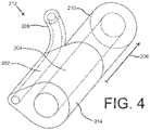
- FIG. 2 shows an embodiment of a dual lumen indwelling catheter, depicted as the catheter 200, which may be configured to indwell a body trunk cavity that provides one or both of a drainage function and an injection function, including seriatim or simultaneously.
- the catheter 200 may be a silicone multi-lumen catheter for long term pleural access to administer medication and drain fluid (i.e., drug and effusion).
- the catheter 200 may allow for a patient to perform drainage and drug administration at home and/or allow for multiple treatments over time with minimal inconvenience to the patient.
- This device can be used to, among other things, deliver therapy for malignant or benign conditions including pulmonary fibrosis and malignant mesothelioma, and cancers with lung metastases.
- the catheter 200 is depicted with two lumens: a first lumen 202 and a second lumen 204.
- the first lumen 202 and the second lumen 204 extend longitudinally through at least a lengthwise portion of a bifurcated length 206 and a binal portion 214.
- the first lumen 202 and the second lumen 204 may be configured for particular functions.
- the first lumen 202 may be configured primarily for the delivery of a substance (e.g., a medication for effecting pleurodesis or a medication for treating cancer) to a target area within the body of a patient, while the second lumen 204 may be configured primarily for a drainage procedure. While not shown, it is contemplated that more than two lumens may be included.
- the two lumens (in a binal embodiment) most preferably are parallel for their entire respective lengths and are not coaxial along any lengthwise portion, although one or both may have a non-circular cross-section and partially surround the other.
- one preferred embodiment includes two lumens along the binal portion that each have a circular cross-section, and that are parallel to each other and a longitudinal central axis of the binal portion.
- the proximal end of the catheter 200 includes the bifurcated length 206 with a first tube portion 208 and a second tube portion 210.
- the first lumen 202 extends through the first tube portion 208 and the second lumen 204 extends through the second tube portion 210, as shown.
- the first tube portion 208 and the second tube portion 210 may be about 4 inches (10. 2 cm) in length (but any suitable length may be used).
- the length of the first tube portion 208 and the second tube portion 210 may be substantially the same or different.
- the first tube portion 208 and the second tube portion 210 join at a junction 212.
- the binal portion 214 which may be made of a flexible silicone providing patient comfort, extends distally from the junction 212, and includes the two lumens 202, 204 extending longitudinally therethrough.
- the binal portion 214 may be a flexible tube-like structure and has two inner diameter surfaces substantially defining side walls of at least a portion of the two lumens 202, 204.
- the binal portion 214 of the catheter 200 may have any suitable length (such as approximately 16 inches (40.6 cm) in at least one exemplary embodiment).
- a distal length 220 of the binal portion 214 is configured to be placed in the body of a patient temporarily or permanently (for example, for a time period of about 6-8 weeks in a non-limiting exemplary embodiment).
- the distal length 220 may be the length of the binal portion 214 that is designed for entry into a patient body, while a so-called proximal length may be the length of the catheter 200 (including both a length of the binal portion 214 and the bifurcated length 206) that generally remains external to the patient body.
- the first tube portion 208 and/or the second tube portion 210 may be associated with a valve (or port) 216, 218. It is contemplated that the valves 216, 218 may be configured for the particular function of their associated lumens.
- the first tube portion 208 may include the first valve 216 which may be configured for the delivery of a medication or another substance. Exemplary valves include Texium ® and Smartsite ® valves marketed by CareFusion ® of San Diego, CA.
- the first valve 216 may be associated with a suitable injection system, such as-for example-a syringe, a pressurized injector, a pump, or any other appropriate means for injection.
- first valve 216 may be designed to be operable (i.e., openable) only by a medical professional and/or only with corresponding equipment generally available only at a medical facility, which may prevent inadvertent and improper access by a patient.
- the second tube portion 210 may include a second valve 218, which may be configured for a drainage procedure.
- An exemplary second valve 218 may be a valve marketed under the name PleurX ® by CareFusion ® , and may be designed for use with drainage equipment, such as vacuum bottles and other suction devices, drainage bags, or the like. It is contemplated that the second valve 218 may be operable by the patient without the presence of a medical professional.
- the described embodiment of the catheter 200 having the first valve 216 and the second valve 218 may simultaneously provide the ability for (1) a medical professional to inject a medication into a patient as needed with a first lumen 202 without risk of the patient inadvertently or improperly accessing the first lumen 202 and (2) the patient to access the second lumen 204 for drainage purposes without the presence of the medical professional.
- the valves 216, 218 and/or the tube portions 208, 210 may be individually marked for ease of identification.
- a cuff element 222 may be located at the proximal end of the distal length 220.
- the cuff element 222 may be provided on the outer surface of the binal portion 214.
- at least the outer diameter surface of the cuff element 222 may contact the skin or other tissue (such as the tissue surface of an incision) at or near the location where the catheter 200 enters the body.
- the cuff element 222 may be tunneled into the body about 1 cm past the incision, and it is contemplated that the cuff element 222 may not be exposed outside the body.
- the cuff element 222 may be textured or otherwise configured to allow and facilitate tissue ingrowth.
- the skin or other tissue of the patient may become secured to the cuff element 222, and the cuff element 222 may provide a seal between internal and external of the patient's body, thereby reducing the risk of infection and other medical complications.
- the cuff element 222 may become part of a sealed barrier continuous and contiguous with the rest of the patient's skin as an integrated part of his/her natural epidermal barrier.
- the cuff element 222 may be made of Dacron TM or another suitable material.
- the cuff element 222 may incorporate an adhesive or another suitable means for attachment/sealing to be used in combination with, or as an alternative to, tissue ingrowth.
- a location immediately adjacent the cuff may include a microtextured surface that may inhibit microbial colonization and migration in/toward the patient's body as described in U.S. Pat. App. No. 15/169,410 to Krueger et al ..
- the binal portion 214 may be formed of a flexible and biocompatible material suitable for deployment in a body trunk cavity.
- the binal portion 214 may include a memory-material configured to guide at least the distal end of the catheter 200 to a target location in a patient body.
- the memory material may include any appropriate metallic or polymeric material upon which shape-memory may be imposed, while allowing flexibility.
- various nitinol and other memory metal compounds are well-known and commonly used in the medical device art.
- Other materials can receive and default-return to a shape (imposed by mechanical, temperature, and/or other means) after flexure into different shape(s).
- the memory configuration may be assumed based upon temperature, release of constraint, and/or by active means.
- the binal portion 214 may additionally or alternatively include one or more one visualization markers 215 configured to be visualizable in a patient body by at least one of fluoroscopy, ultrasound, magnetic resonance imaging, and computed tomography, or another suitable technology.
- the visualization marker(s) may assist medical personnel during deployment of the catheter 200, for example.
- the lumens 202, 204 may have any suitable cross-sectional size.
- the diameter of the lumens 202, 204 may be between about 0.005 inches (0.13 mm) and about 1 inch (2.5 cm), such as from about 0.030 (0.76 mm) to about 0.300 inches (7.6 mm).
- the first lumen 202 and the second lumen 204 have different cross-sectional dimensions.
- the diameter of the first lumen 202 may be a diameter suitable for a relatively precise injection procedure (such as a diameter of about 0.050 inches (1.3 mm)), and the diameter of the second lumen 204 may be suitable for the performance of a relatively less-precise drainage procedure (such as about 0.100 inches (2.5 mm)).
- the diameter (or other cross-sectional dimension) of the second lumen 204 may be about 1.5 times larger than the diameter (or other cross-sectional dimension) of the first lumen 202, about 2 times larger, about 3 times larger, about 4 times larger, etc.
- the diameter of the first lumen 202 may be about 0.044 inches (1.12 mm) (and the outer diameter of the tube forming the first lumen 202 may be about 0.063 inches (1.6 mm)), and the diameter of the second lumen 204 may be about 0.095 inches (2.41 mm) (and the outer diameter of the tube forming the second lumen 204 may be about 0.200 inches (5.1 mm)), which may provide a desirable flow rate and wall thickness in certain medical applications.
- FIG. 4 shows an embodiment of the junction 212 in detail.
- the junction 212 may be a separate component from tubing forming the bifurcated length 206 and/or the binal portion 214 (e.g., it may be a component formed separately from, and then attached to, the first tube portion 208, the second tube portion 210, and/or the binal portion 214).
- the binal portion 214 may merely be a point where two tubes are connected to one another at a contact point (through use of an adhesive, through fusing, etc.) (see FIG. 2 ).
- the binal portion 214 is ovular in cross-section, as shown.
- the junction may include a visual indicator, such as a barium stripe.
- the binal portion 214 may be sized or otherwise configured to be directed through an introducer 224, which may include a pinch valve 226 as shown.
- the outer perimeter of the binal portion 214 may be configured (e.g., dimensioned) to fit within a channel of a commercially-available introducer 224.
- the valved introducer 224 may control both lumens 202, 204 at the same time, which may be desirable when a medical function requires synchronized function of the lumens 202, 204, for example.
- the introducer 224 may be configured as a commercially available splittable introducer of any type already known in the art for introduction of a tubular device through a body wall or other structure, followed by subsequent removal of the introducer circumferentially encompassing the introduced device.
- FIG. 6 shows a bottom view of four embodiments of a distal end of a dual lumen indwelling catheter 300 with fenestrations 326 through the side wall of at least one lumen.
- the fenestrations 326 may serve as an inlet and/or an outlet for one or more lumens of the catheter 300, such as an injection lumen (e.g., the first lumen 202 of FIG. 1-FIG. 2 ) and/or a drainage lumen (e.g., the second lumen 204 of FIG. 1-FIG. 2 ).
- the fenestrations 326 may serve as the only inlet or outlet, but in other embodiments an opening may be provided at the distal terminus 328 of the catheter 300 (as shown in FIG. 2 , for example). As shown in embodiment A of FIG. 6 , the fenestrations 326 may be spaced apart with approximate consistency along the length of the distal end of the catheter 300. Also, as depicted, the fenestrations 326 may be elliptical rather than circular in cross-section, though no particular shape is required in the present disclosure. Each of the fenestrations may be about the same size, as shown. The fenestrations may also have valve-type configuration(s) that render them effectively one-way for inlet or outlet functionality.
- a catheter 400 may have fenestrations 426 with an unequal spacing, as depicted by embodiment B.
- the space between each of the fenestrations 426 may decrease nearer a distal terminus 428.
- this embodiment may provide a relatively even distribution of medication when the fenestrations 426 are associated with an injection lumen. The advantageous characteristics of this embodiment are discussed in more detail with respect to FIG. 7 below.
- the size of two or more fenestrations 526 may vary along the length of a catheter 500.
- the size of the fenestrations 526 may increase nearer a distal terminus 528. Similar as to in embodiment B, this embodiment may provide a relatively even distribution of medication when the fenestrations 526 are associated with an injection lumen, which is described in more detail below with respect to FIG. 7 .
- a catheter 600 may have fenestrations 626 with a cross-sectional shape that acts as a nozzle.
- the nozzle-like fenestrations 626 may inject a medication or other substance into the body of a patient with a relatively high velocity and may focus the flow of the medication precisely on a target location within the patient body.
- the nozzle-like fenestrations 626 may be any suitable shape and size. Further, two or more of the shape, size, and spacing characteristics described herein can be combined in any suitable manner to optimize the catheter 600 for a particular function.
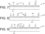
- FIG. 7 shows an illustration of the flow of a medication (e.g., a medicament or other substance) as it is injected into the body of a patient by a first lumen 702 of a catheter 700.
- Medications dispensable through the first lumen 702 may include sclerosis-inducing agent(s), therapeutic agent(s), chemotherapy agent(s), gene therapy agent(s), and/or other materials.
- Medications may be configured as liquids, solutions, suspensions, gels, pastes, or any combination thereof and may include effervescent material (e.g., sodium bicarbonate and citric acid or other combination that can be activated by temperature, liquid-contact, or other means) configured to aid dispersion through the body cavity by formation of bubbles and/or spreading by similar means.
- effervescent material e.g., sodium bicarbonate and citric acid or other combination that can be activated by temperature, liquid-contact, or other means
- Examples of medications may include talc, silver nitrate, bleomycin, and/or other sclerosis-inducing agents.
- examples of medicaments may include chemotherapy agents, antibiotic(s), loculation-breakup compound(s) (e.g., tissue plasminogen activator tPA), and/or other materials.
- a biologic fluid e.g., a patient's own blood, immunotherapy, or other biologic agent
- the catheter 700 may include the first lumen 702 with the fenestrations 726 and a second lumen 704 (which may also include fenestrations that are not shown).
- Each of the fenestrations 726 may be about the same size, and the spacing between each of the fenestrations 726 may be about the same.
- the fluid 730 may experience a total pressure loss due to (1) a friction-related pressure drop and (2) a loss of pressure corresponding to a flow-rate out of the lumen 702 at each outlet (i.e., each fenestration 726).
- the injection pressure (herein defined as the pressure of the fluid 730 in the lumen 702 just before it discharges from a fenestration 726) of the fluid 730 will decrease with respect to each distally-successive fenestration 726.
- the fluid may be injected into a patient at a decreasing flow rate with respect to each distally-successive fenestration 726.
- This embodiment may be advantageous where it is desired to vary the flow rate of a medication at different locations within a patient body.
- FIG. 8 shows an illustration of an injection procedure by a second embodiment of a catheter 800 with first and second lumens 802, 804.
- the catheter 800 is depicted as having features similar to the catheter 700 of FIG. 7 , but with decreasing spacing between the fenestrations 826 with respect to the distal direction.
- the injection pressure of the medication 830 may be more consistent along the length of the catheter 800 such that the medication 830 is released relatively evenly (i.e., the flow rate out of each of the fenestrations 826 varies less).
- this embodiment may provide for a more consistent application of the medication at a treatment site within a patient body.
- FIG. 9 shows a similar effect may be achieved by increasing the size of each distally-successive fenestration of a catheter (for example, as shown by embodiment C of FIG. 6 ).
- a catheter 900 (with lumens 902, 904) may include fenestrations 926 that increase in size distally.
- the flow rate of the medication 930 out of a fenestration is a function of both (1) the injection pressure, and (2) the size (and shape) of the fenestration. Accordingly, larger fenestrations will provide for a higher injection flow rate.
- each of the fenestrations can be optimized such that the flow rate is relatively consistent along the length of the catheter to thereby advantageously provide even distribution of the medication at a treatment site. It is contemplated that the fenestrations 926 may be designed to purposely vary the injection flow rate along the length of the catheter to vary the distribution of the medication in a controlled manner.
- a catheter may have fenestrations with a combination of varying size and varying spacing to achieve a desirable distribution of an injected medication.
- more than one lumen of the catheter may incorporate these described characteristics related to fenestrations.
- one or both of the first lumen 202 and the second lumen 204 may incorporate fenestrations having different sizes and different spaces therebetween.
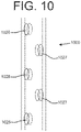
- a catheter 1000 may include fenestrations 1026, 1027 that are offset with respect to the longitudinal direction of the catheter 1000. This feature may be combined with any of the other fenestration-related characteristics described above.
- a medication may be injected consistently with respect to the radial direction to further enhance the distribution of a medication. While advantages of the herein-described fenestration-related characteristics are primarily described with reference to injecting a substance, those same advantages (or similar advantages) may also apply with respect to a drainage procedure.
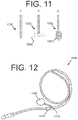
- one or more lumens of a catheter may include a distal end configured for a particular distribution of an injected medication (and/or drainage).
- the distal end 1132 may include a tapered tip configured to act as a nozzle to inject a medication or other substance with a high velocity and high focus in the longitudinal direction.
- the distal end 1232 may include a plurality of extremities 1234, where each of the extremities 1234 includes at least one outlet such that the medication is injected in many different directions.
- extremities 1234 may be flexible, and they may be protected by a removable sheath (not shown) during the deployment of the catheter, for example.
- a balloon tip 1334 with a plurality of outlets may be included on the distal end 1332 as shown by embodiment C.
- the balloon tip 1334 may be in fluid communication with at least one lumen of the catheter, and may expand when under pressure (e.g., when an injection pressure is present).
- FIG. 12 shows an embodiment of a catheter 1400, which may be a dual lumen indwelling catheter similar to the catheter 200 of FIG. 2 , but with a port 1450.
- the port 1450 may be a medical appliance that is deployed beneath the skin of a patient with a septum or other membrane through which can be injected.
- the septum may be located near the surface of the skin of the patient such that a needle can penetrate the skin and the septum to access a cavity of the port 1450.
- the cavity of the port 1450 may be in fluid communication with an injection lumen of the catheter 1400 such that the port 1450 provides an interface between a medical professional and the injection lumen of the catheter 1400.
- the injection lumen of the catheter 1400 may direct the injected medication or other substance from the port 1450 to a target location within the patient body as described in detail above.
- a cuff element 1422 may be included proximal to a junction 1412, as shown. It is also contemplated that the cuff element 1422 could be distal to the junction 1412. Embodiments with a port are described in more detail below.
- FIG. 13 shows a distal end of a catheter 1500 with a bifurcated distal length having separated distal tube portions depicted as the first distal tube portion 1540 and the second distal tube portion 1542.
- the distal tube portions may be formed of a flexible silicone to provide patient comfort and in some embodiments may include a memory material for deployment to a specific area of a body cavity.
- the first distal tube portion 1540 and the second distal tube portion 1542 may extend from a binal portion 1514.
- a first lumen 1502 which may be an injection lumen, may extend through the binal portion 1514 and the first distal tube portion 1540.
- the second lumen 1504 which may be a drainage lumen, may extend through the binal portion 1514 and the second distal tube portion 1542.
- the depicted bifurcated distal length of FIG. 13 may be combined with any of the embodiments disclosed herein.
- FIG. 14 shows a catheter 1600 having a bifurcated distal length with a first distal tube portion 1640 and a second distal tube portion 1642.
- the bifurcated distal length may be configured for deployment within a body cavity, such as the pleural space 1660 surrounding a lung 1662.
- the catheter 1600 also has a bifurcated proximal length with a first proximal tube portion 1608 and a second proximal tube portion 1610.
- the first proximal tube portion 1608 may include a first lumen, which may extend from the first proximal tube portion 1608, through a binal portion 1614, and to the first distal tube portion 1640.
- the first lumen may be an injection lumen similar to as described above, and the first distal tube portion 1640 may include a distal end with fenestrations for providing a particular distribution of an injected medication (e.g., the fenestrations of FIGS. 7-10 and/or the end features of FIG. 11 ).
- a first valve 1616 may provide access to the first lumen.
- the second lumen may be a drainage lumen similar to as described above, and the second distal tube portion 1642 may include fenestrations and/or other end features configured for drainage.
- a second valve 1618 which may be a different valve than the first valve 1616, may provide access to the second lumen.
- a cuff element 1622 may be included on the binal portion 1614 (or another portion) and may be configured for facilitating tissue ingrowth, as described above.
- the embodiment of FIG. 14 may be advantageous for providing a lavage process of circulating a fluid through a body cavity.
- a fluid medication or other fluid may be injected into an injection lumen at the first proximal tube portion 1608 through the first valve 1616.
- the fluid may the travel through the injection lumen of the catheter 1600 to a distal end of the first distal tube portion 1640, where it is injected into the depicted pleural space 1660.
- the first distal tube portion 1640 may be maneuvered in the pleural space during installation such that it is located at a relatively high location with respect to the second distal tube portion 1642.
- the fluid may be pulled at least partially by the force of gravity through the pleural space 1660 to a respectively lower location (making contact with, and/or traveling through, the lung 1662, on its way).
- the second distal tube portion 1642 may be located at that relatively lower location to drain and remove the fluid from the pleural space 1660. It is contemplated that drainage lumen of the second distal tube portion 1642 may provide a suction force to facilitate the flow of the fluid.
- the fluid may then be pulled through the drainage lumen and exit the catheter 1600 at the second proximal tube portion 1610 through the second valve 1618.
- the first and second valves may be different valve models configured for their particular function (e.g., drainage or injection).
- FIG. 15 shows an embodiment of a catheter 1700 similar to the catheter 1600 of FIG. 14 , but including a port 1750.
- the port 1750 may be located beneath the outer surface 1764 of the skin of a patient, and may provide an interface between a medical professional and a lumen (e.g., an injection lumen) of the catheter 1700.
- the port 1750 may be located on a first proximal tube portion 1708 associated with the injection lumen.
- a needle or other device may be used to penetrate the skin and a septum of the port 1750 to inject a fluid into the port 1750, which may then flow to a distal end of the first distal tube portion 1740.
- the fluid may then move through the body cavity and be drained through the second distal tube portion 1742 and circulated back out of the catheter 1700 through the valve 1718.
- This embodiment may be advantageous for concealing at least one of the proximal tube portions (in this case, the first proximal tube portion 1708). Further, it may ensure the first proximal tube portion 1708 is not confused with the second proximal tube portion 1710 and/or may ensure the injection lumen of the first proximal tube portion 1708 remains relatively inaccessible to the patient.
- the second proximal tube portion 1710 may remain accessible to the patient, and may be used in isolation by a medical professional, the patient, or another person to perform a drainage procedure separate from a lavage process. It is also contemplated that the port 1750 may be utilized during an injection procedure separate from a lavage process.
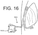
- FIG. 16 Another embodiment of a dual lumen catheter 1800 is shown in FIG. 16 .
- the catheter 1800 may be similar to the catheters 1600, 1700 of FIGS. 14-15 , but may include a circulating pump 1852.
- the circulating pump 1852 may receive a lavage fluid from a drainage lumen of the catheter 1800 and then circulate that fluid back to a body cavity through an injection lumen.
- This embodiment may be advantageous where it is desirable to circulate a medication through a particular area of a body cavity multiple times.
- the fluid circulated through the catheter 1800 may be a suitable mixture of medication and body fluid or saline with a suitable concentration of the medication.
- the circulating pump 1852 may be programmed to turn on and off automatically such that an appropriate number of lavage treatments are performed and such that each lavage treatment is performed for an appropriate amount of time.
- the circulation pump may optionally include filtration elements up to and including highly selective filters such as used in various dialysis machines, physically and/or chemically selective-binding elements, and/or other elements configured to remove, replace, and/or add in predetermined materials from/to the fluid and/or fluid-borne mixture. It is contemplated that the circulating pump 1852 may be controlled by the patient and/or the medical professional. In some embodiments, the circulating pump 1852 may be associated with a sensor that provides feedback to a pump controller.
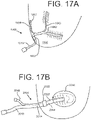
- a catheter 1900 may be deployed in the peritoneal cavity 1966.
- the catheter 1900 may include a first distal tube portion 1940 configured primarily for the injection of a fluid (e.g., a medication) and a second distal tube portion 1942 configured primarily for drainage.
- a fluid e.g., a medication
- the catheter 1900 may include a first proximal tube portion 1908 with a port 1950 that remains under the skin of a patient and a second proximal tube portion 1910 that extends externally from the body of the patient when deployed.
- a cuff element 1922 may be located on the second proximal tube portion 1910, as shown.
- a dual lumen catheter 2000 may be associated with an organ 2068 (e.g., a bladder).
- the catheter 2000 may have a bifurcated length with the first and second proximal tube portions 2008 and 2010 configured respectively for injection and drainage, for example, and respectively associated with an injection lumen 2002 and drainage lumen 2004.
- a binal portion 2014 may extend distally from the proximal tube portions to and beyond a sealing element 2022 and into the organ 2068. It is contemplated that a seal may be created where the binal portion 2014 enters the organ 2068.
- the organ 2068 when the organ 2068 is a urinary bladder, it may be necessary to provide a second and/or further plural sealing element(s) at the entry location of the bladder or other organ 2068 such that fluid from within the bladder does not leak to other areas of the patient body.
- the catheter 2000 is depicted without a bifurcated distal end, but this is not required.
- injected fluid may be circulated through the organ 2068 by injecting through the injection lumen 2002 and draining through the drainage lumen 2004 simultaneously (or seriatim, in this and other embodiments).
- FIG. 18 shows an embodiment of a dual lumen indwelling catheter with separable or splittable tube portions.
- the catheter 2100 may include a proximal bifurcated length 2106, a distal bifurcated length 2107, and a binal portion 2114 therebetween.
- the binal portion 2114 of the catheter 2100 may have a first lumen 2102 and a second lumen 2104 that are separable or splittable.
- the first lumen 2102 and the second lumen 2104 may be connected via a relatively weak connection such that they can be pulled apart by a medical professional.
- the catheter 2100 may therefore have dimensions that are adjustable to a particular medical procedure in a particular patient.
- the catheter 2100 of FIG. 18 may be modified by a medical professional just before deployment rather than in a manufacturing facility.
- the bifurcated tube portions of the proximal bifurcated length 2106 may have different lengths (and, similarly, the lengths of the tube portions of the distal bifurcated length 2107 may be different).
- the lengths of these tube portions may be optimized for certain conditions and functions. For example, when a tube portion is associated with a port that may remain under the skin, it may be short with respect to a tube portion that will extend externally from a patient body. Similarly, a tube portion that must extend to a relatively remote location within a body cavity may be relatively long when compared to an internal tube portion.
- the length of the tube portions may be formed during the manufacturing of the catheter 2100.
- a medical professional may have the ability to cut one or more of the tube portions to an appropriate length before or during the deployment of the catheter 2100 (which may require attaching certain components, such as a valve and/or a port, after cutting the tube portions to length).
- an internal portion of a catheter disclosed herein may be configured to vibrate or otherwise move during injection, and/or a device may be utilized to vibrate the patient's body (e.g., a vibrating chair).
- a pump connected to an injection lumen may provide a pulsing injection pressure, and/or a vacuum force associated with a drainage lumen may pulse. Injection may be continuous for a long period of time, or not. In some circumstances, it may be advantageous to use a single-use disposable pump designed to deliver (and/or drain) a precise amount of a medication or other fluid.
- a drug may be injected for minutes, hours, or days, followed by later drainage (or, alternatively, drainage can occur during or even before injection). Further, different drug types may be injected in a particular sequence. Injected drugs may be solid or liquid (including hydrogel) and may be heated or cooled. A sensor may be associated with the indwelling catheter to measure a parameter (such drug concentration in the body or in a drained fluid, for example), which may provide feedback to the patient, a medical professional, and/or an automatic system.
- a parameter such drug concentration in the body or in a drained fluid, for example
- a dual lumen indwelling catheter as described herein may provide the ability to inject a medication, such as a cancer-treating chemotherapy drug, into a body cavity and then remove that same medication before it can cause substantial damage to surrounding healthy tissue.
- a medication such as a cancer-treating chemotherapy drug
- This injection may be accomplished without surgery and it may be repeatable.
- the dose of medication may be optimized in view of the ability to repeat the procedure.
- the disclosed device could be utilized for other local treatments, such as localized antibiotic application, intentional introduction of chemical pleurodesis, immunotherapy or biologic therapy, or any other suitable procedure involving the introduction and/or the removal of fluid or other substances.
Description
- Embodiments of the present disclosure relate to catheters for performing medical procedure involving a drainage function and/or an injection function.
- Chemotherapy generally refers to the use of medicines or drugs to destroy cancer cells. Typically, the chemotherapy drugs are delivered via intravenous methods or by taking capsules orally, thereby distributing the drug throughout the body. The toxic nature of the drug often affects healthy cells as well as cancer cells, which can cause a series of unpleasant side effects such as nausea, damage to the immune system, fatigue, and hair loss.
- Recently, it has been found that cancer cells may be treated with localized application of chemotherapy drugs. For example, in one procedure called heated intraperitoneal chemoperfusion ("HIPEC"), warmed chemotherapy medication is circulated in the peritoneal cavity immediately after the surgical removal of tumors. The chemotherapy drugs are then removed from the peritoneal cavity after a short time to prevent substantial damage to surrounding body tissue. While effective, HIPEC can only be performed after invasive surgical procedures granting sufficient access to the body cavity. Because surgical procedures are typically infrequent, repeat local application is usually not possible since access to the body cavity is generally limited in duration.
- In view of this background, a medical device providing access to a body cavity for the injection and drainage of a medication without substantial invasiveness would be advantageous.
US 2009/0292248 describes a multiple catheter assembly comprising a first catheter having a first distal end region and an outer surface defining at least a first lumen, and a second catheter having a second distal end region and a second outer surface defining at least a second lumen. The outer surfaces of the first and second catheters are releasably joined by a splittable bond for allowing the first and second distal tips to be at least partially longitudinally split from each other. The first and second distal end regions are separated and inserted in juxtaposed relation to each other through an incision and into an area to be catheterized.US 2003/0153898 describes a multi-lumen catheter assembly with a unitary portion and at least two distal end tubes extending distally from the unitary portion. The unitary portion includes an exterior having a generally round or oval shape in cross section and includes at least two distal end tubes of generally circular (or other) cross sectional shape extending longitudinally therethrough. The catheter assembly may be made by extruding a unitary tube having internal longitudinally extending lumens (of circular or other shape), then splitting the tube on its distal end portion to form distal end tubes.US 2003/0149395 describes a split tip dialysis catheter having an outer tube and an inner tube, in which the two tubes can be arranged over at least a portion of their length in a coaxial configuration.US 2006/0058731 describes an implantable peritoneal dialysis device.US 2007/0255230 describes a cannula that has openings of different size to permit a surgeon to selectively control the distribution pattern of a flowable material through the cannula and into a patient.US2007/073271 describes a catheter for use in introducing fluid into a vessel or other bodily structure. - The invention provides a catheter according to claim 1. Further aspects of the invention are provided in the dependent claims 2-9. Embodiments that do not fall within the scope of the claims are to be interpreted as examples useful for understanding the invention.
-
-
FIG. 1 illustrates a drainage apparatus as known in the prior art. -
FIG. 2 shows an embodiment of a dual lumen indwelling catheter in accordance with the present disclosure. -
FIG. 3 shows a magnified view of the distal end of the dual lumen indwelling catheter ofFIG. 2 . -
FIG. 4 shows an embodiment of a junction for a dual lumen indwelling catheter in accordance with the present disclosure. -
FIG. 5 shows a system with a dual lumen indwelling catheter and an introducer in accordance with the present disclosure. -
FIG. 6 shows a bottom view of four (4) embodiments of a distal end of a dual lumen indwelling catheter with fenestrations in accordance with the present disclosure. -
FIG. 7 shows an illustration of the flow of a substance as it is injected by a lumen of a dual lumen indwelling catheter in accordance with the present disclosure. -
FIG. 8 shows an illustration of the flow of a substance as it is injected by a lumen of a second embodiment of a dual lumen indwelling catheter in accordance with the present disclosure. -
FIG. 9 shows an illustration of the flow of a substance as it is injected by a lumen of a third embodiment of a dual lumen indwelling catheter in accordance with the present disclosure. -
FIG. 10 shows an embodiment of a distal end of a dual lumen catheter with offset fenestrations in accordance with the present disclosure. -
FIG. 11 shows embodiments of tips of a dual lumen indwelling catheter in accordance with the present disclosure. -
FIG. 12 shows an embodiment of a dual lumen indwelling catheter with a port in accordance with the present disclosure. -
FIG. 13 shows a distal end of an embodiment of a catheter with bifurcated distal length having separated distal tube portions in accordance with the present disclosure. -
FIG. 14 shows an embodiment of a dual lumen indwelling catheter with a bifurcated distal length in accordance with the present disclosure. -
FIG. 15 shows an embodiment of a dual lumen indwelling catheter with a bifurcated distal length and including a port in accordance with the present disclosure. -
FIG. 16 shows an embodiment of a dual lumen indwelling catheter with a circulating pump in accordance with the present disclosure. -
FIGS. 17A-B show two embodiments of a dual lumen indwelling catheter deployed in a peritoneal cavity and an organ, respectively, in accordance with the present disclosure. -
FIG. 18 shows an embodiment of a dual lumen indwelling catheter with separable tube portions and variable tube portion lengths in accordance with the present disclosure. - Embodiments generally are described with reference to the drawings in which like elements are generally referred to by like numerals. The relationship and functioning of the various elements of the embodiments may better be understood by reference to the following detailed description. However, embodiments are not limited to those illustrated in the drawings. It should be understood that the drawings are not necessarily to scale (including that relative lengths and other proportions may be the same as or different than various illustrations herein), and in certain instances details may have been omitted that are not necessary for an understanding of embodiments of the present invention, such as-for example-conventional fabrication and assembly.
- Medical drainage procedures may be performed with drainage devices of the type shown in
FIG. 1 . Theapparatus 100 is shown as installed in a patient body and includes adrainage container 114. Thedrainage container 114 is removably attached by aproximal tube 110 at avalve 60 to a distal catheter 12. Thevalve 60 may be configured in any number of ways known in the art for attaching catheters together in a fluid-patent manner, (which may include a two-part valve), and the proximal portion attached to the distal catheter 12 may be configured to be self-sealing when disconnected from theproximal tube 110. The proximal end portion of the distal catheter 12 is shown indwelling the patient, disposed through the body wall 21 into anintra-body space 23, which may be - for example - a pleural, peritoneal, or other body lumen. That proximal portion includes acuff element 19 and a flexible fluid-intake length 14 includingfenestrations 18, shown in theintra-body space 23. This structure may be better understood with reference toU.S. Pat. No. 5,484,401 , and with reference to commercial products marketed under the name PleurX® by CareFusion® of San Diego, CA. Another structure that may be useful for providing such a method is disclosed inU.S. App. Pub. No. 2015/0174375 to DeVries et al . and with reference to commercial products marketed under the name PleurX® by CareFusion® of San Diego, CA. - It would additionally be advantageous to provide a single indwelling catheter that can perform the above-described drainage function, but also can deliver a drug to a body cavity without substantially increasing the invasiveness of the device.
FIG. 2 shows an embodiment of a dual lumen indwelling catheter, depicted as thecatheter 200, which may be configured to indwell a body trunk cavity that provides one or both of a drainage function and an injection function, including seriatim or simultaneously. Thecatheter 200 may be a silicone multi-lumen catheter for long term pleural access to administer medication and drain fluid (i.e., drug and effusion). Thecatheter 200 may allow for a patient to perform drainage and drug administration at home and/or allow for multiple treatments over time with minimal inconvenience to the patient. This device can be used to, among other things, deliver therapy for malignant or benign conditions including pulmonary fibrosis and malignant mesothelioma, and cancers with lung metastases. - The
catheter 200 is depicted with two lumens: afirst lumen 202 and a second lumen 204. Thefirst lumen 202 and the second lumen 204 extend longitudinally through at least a lengthwise portion of a bifurcated length 206 and abinal portion 214. Thefirst lumen 202 and the second lumen 204 may be configured for particular functions. For example, thefirst lumen 202 may be configured primarily for the delivery of a substance (e.g., a medication for effecting pleurodesis or a medication for treating cancer) to a target area within the body of a patient, while the second lumen 204 may be configured primarily for a drainage procedure. While not shown, it is contemplated that more than two lumens may be included. The two lumens (in a binal embodiment) most preferably are parallel for their entire respective lengths and are not coaxial along any lengthwise portion, although one or both may have a non-circular cross-section and partially surround the other. However, one preferred embodiment includes two lumens along the binal portion that each have a circular cross-section, and that are parallel to each other and a longitudinal central axis of the binal portion. - The proximal end of the
catheter 200 includes the bifurcated length 206 with afirst tube portion 208 and asecond tube portion 210. Thefirst lumen 202 extends through thefirst tube portion 208 and the second lumen 204 extends through thesecond tube portion 210, as shown. In at least one exemplary embodiment, thefirst tube portion 208 and thesecond tube portion 210 may be about 4 inches (10. 2 cm) in length (but any suitable length may be used). The length of thefirst tube portion 208 and thesecond tube portion 210 may be substantially the same or different. Thefirst tube portion 208 and thesecond tube portion 210 join at ajunction 212. Thebinal portion 214, which may be made of a flexible silicone providing patient comfort, extends distally from thejunction 212, and includes the twolumens 202, 204 extending longitudinally therethrough. Thebinal portion 214 may be a flexible tube-like structure and has two inner diameter surfaces substantially defining side walls of at least a portion of the twolumens 202, 204. Thebinal portion 214 of thecatheter 200 may have any suitable length (such as approximately 16 inches (40.6 cm) in at least one exemplary embodiment). A distal length 220 of thebinal portion 214 is configured to be placed in the body of a patient temporarily or permanently (for example, for a time period of about 6-8 weeks in a non-limiting exemplary embodiment). Herein, the distal length 220 may be the length of thebinal portion 214 that is designed for entry into a patient body, while a so-called proximal length may be the length of the catheter 200 (including both a length of thebinal portion 214 and the bifurcated length 206) that generally remains external to the patient body. - The
first tube portion 208 and/or thesecond tube portion 210 may be associated with a valve (or port) 216, 218. It is contemplated that thevalves first tube portion 208 may include thefirst valve 216 which may be configured for the delivery of a medication or another substance. Exemplary valves include Texium® and Smartsite® valves marketed by CareFusion® of San Diego, CA. Thefirst valve 216 may be associated with a suitable injection system, such as-for example-a syringe, a pressurized injector, a pump, or any other appropriate means for injection. It is contemplated that thefirst valve 216 may be designed to be operable (i.e., openable) only by a medical professional and/or only with corresponding equipment generally available only at a medical facility, which may prevent inadvertent and improper access by a patient. - The
second tube portion 210 may include asecond valve 218, which may be configured for a drainage procedure. An exemplarysecond valve 218 may be a valve marketed under the name PleurX® by CareFusion®, and may be designed for use with drainage equipment, such as vacuum bottles and other suction devices, drainage bags, or the like. It is contemplated that thesecond valve 218 may be operable by the patient without the presence of a medical professional. Advantageously, the described embodiment of thecatheter 200 having thefirst valve 216 and thesecond valve 218 may simultaneously provide the ability for (1) a medical professional to inject a medication into a patient as needed with afirst lumen 202 without risk of the patient inadvertently or improperly accessing thefirst lumen 202 and (2) the patient to access the second lumen 204 for drainage purposes without the presence of the medical professional. Thevalves tube portions - A cuff element 222 may be located at the proximal end of the distal length 220. The cuff element 222 may be provided on the outer surface of the
binal portion 214. When installed, at least the outer diameter surface of the cuff element 222 may contact the skin or other tissue (such as the tissue surface of an incision) at or near the location where thecatheter 200 enters the body. In some embodiments, for example, the cuff element 222 may be tunneled into the body about 1 cm past the incision, and it is contemplated that the cuff element 222 may not be exposed outside the body. The cuff element 222 may be textured or otherwise configured to allow and facilitate tissue ingrowth. Over time, the skin or other tissue of the patient may become secured to the cuff element 222, and the cuff element 222 may provide a seal between internal and external of the patient's body, thereby reducing the risk of infection and other medical complications. In other words, the cuff element 222 may become part of a sealed barrier continuous and contiguous with the rest of the patient's skin as an integrated part of his/her natural epidermal barrier. The cuff element 222 may be made of Dacron™ or another suitable material. The cuff element 222 may incorporate an adhesive or another suitable means for attachment/sealing to be used in combination with, or as an alternative to, tissue ingrowth. It is contemplated that a location immediately adjacent the cuff may include a microtextured surface that may inhibit microbial colonization and migration in/toward the patient's body as described inU.S. Pat. App. No. 15/169,410 to Krueger et al .. - The
binal portion 214 may be formed of a flexible and biocompatible material suitable for deployment in a body trunk cavity. In some embodiments, thebinal portion 214 may include a memory-material configured to guide at least the distal end of thecatheter 200 to a target location in a patient body. The memory material may include any appropriate metallic or polymeric material upon which shape-memory may be imposed, while allowing flexibility. For example, various nitinol and other memory metal compounds are well-known and commonly used in the medical device art. Other materials can receive and default-return to a shape (imposed by mechanical, temperature, and/or other means) after flexure into different shape(s). The memory configuration may be assumed based upon temperature, release of constraint, and/or by active means. Thebinal portion 214 may additionally or alternatively include one or more one visualization markers 215 configured to be visualizable in a patient body by at least one of fluoroscopy, ultrasound, magnetic resonance imaging, and computed tomography, or another suitable technology. The visualization marker(s) may assist medical personnel during deployment of thecatheter 200, for example. - The
lumens 202, 204 may have any suitable cross-sectional size. For example, when thelumens 202, 204 have circular cross-sections (seeFIG. 3 ), the diameter of thelumens 202, 204 may be between about 0.005 inches (0.13 mm) and about 1 inch (2.5 cm), such as from about 0.030 (0.76 mm) to about 0.300 inches (7.6 mm). As best shown byFIG. 3 , thefirst lumen 202 and the second lumen 204 have different cross-sectional dimensions. For example, the diameter of thefirst lumen 202 may be a diameter suitable for a relatively precise injection procedure (such as a diameter of about 0.050 inches (1.3 mm)), and the diameter of the second lumen 204 may be suitable for the performance of a relatively less-precise drainage procedure (such as about 0.100 inches (2.5 mm)). The diameter (or other cross-sectional dimension) of the second lumen 204 may be about 1.5 times larger than the diameter (or other cross-sectional dimension) of thefirst lumen 202, about 2 times larger, about 3 times larger, about 4 times larger, etc. In one exemplary embodiment, the diameter of thefirst lumen 202 may be about 0.044 inches (1.12 mm) (and the outer diameter of the tube forming thefirst lumen 202 may be about 0.063 inches (1.6 mm)), and the diameter of the second lumen 204 may be about 0.095 inches (2.41 mm) (and the outer diameter of the tube forming the second lumen 204 may be about 0.200 inches (5.1 mm)), which may provide a desirable flow rate and wall thickness in certain medical applications. -
FIG. 4 shows an embodiment of thejunction 212 in detail. Thejunction 212 may be a separate component from tubing forming the bifurcated length 206 and/or the binal portion 214 (e.g., it may be a component formed separately from, and then attached to, thefirst tube portion 208, thesecond tube portion 210, and/or the binal portion 214). In some embodiments, thebinal portion 214 may merely be a point where two tubes are connected to one another at a contact point (through use of an adhesive, through fusing, etc.) (seeFIG. 2 ). Thebinal portion 214 is ovular in cross-section, as shown. It can be advantageous to use an ovular cross-section when twolumens 202, 204 are provided due to the relatively small surface area and relatively smooth and continuous outer-perimeter shape. While not shown, the junction may include a visual indicator, such as a barium stripe. - Referring to
FIG. 5 , in some embodiments, thebinal portion 214 may be sized or otherwise configured to be directed through an introducer 224, which may include a pinch valve 226 as shown. For example, the outer perimeter of thebinal portion 214 may be configured (e.g., dimensioned) to fit within a channel of a commercially-available introducer 224. Advantageously, the valved introducer 224 may control bothlumens 202, 204 at the same time, which may be desirable when a medical function requires synchronized function of thelumens 202, 204, for example. The introducer 224 may be configured as a commercially available splittable introducer of any type already known in the art for introduction of a tubular device through a body wall or other structure, followed by subsequent removal of the introducer circumferentially encompassing the introduced device. -
FIG. 6 shows a bottom view of four embodiments of a distal end of a dual lumenindwelling catheter 300 withfenestrations 326 through the side wall of at least one lumen. Thefenestrations 326 may serve as an inlet and/or an outlet for one or more lumens of thecatheter 300, such as an injection lumen (e.g., thefirst lumen 202 ofFIG. 1-FIG. 2 ) and/or a drainage lumen (e.g., the second lumen 204 ofFIG. 1-FIG. 2 ). In some embodiments, thefenestrations 326 may serve as the only inlet or outlet, but in other embodiments an opening may be provided at thedistal terminus 328 of the catheter 300 (as shown inFIG. 2 , for example). As shown in embodiment A ofFIG. 6 , thefenestrations 326 may be spaced apart with approximate consistency along the length of the distal end of thecatheter 300. Also, as depicted, thefenestrations 326 may be elliptical rather than circular in cross-section, though no particular shape is required in the present disclosure. Each of the fenestrations may be about the same size, as shown. The fenestrations may also have valve-type configuration(s) that render them effectively one-way for inlet or outlet functionality. - A
catheter 400 may have fenestrations 426 with an unequal spacing, as depicted by embodiment B. For example, as shown, the space between each of thefenestrations 426 may decrease nearer adistal terminus 428. Advantageously, this embodiment may provide a relatively even distribution of medication when thefenestrations 426 are associated with an injection lumen. The advantageous characteristics of this embodiment are discussed in more detail with respect toFIG. 7 below. - Referring to embodiment C, the size of two or more fenestrations 526 may vary along the length of a
catheter 500. For example and as shown, the size of thefenestrations 526 may increase nearer a distal terminus 528. Similar as to in embodiment B, this embodiment may provide a relatively even distribution of medication when thefenestrations 526 are associated with an injection lumen, which is described in more detail below with respect toFIG. 7 . - As represented by embodiment D of
FIG. 6 , acatheter 600 may have fenestrations 626 with a cross-sectional shape that acts as a nozzle. Advantageously, the nozzle-like fenestrations 626 may inject a medication or other substance into the body of a patient with a relatively high velocity and may focus the flow of the medication precisely on a target location within the patient body. The nozzle-like fenestrations 626 may be any suitable shape and size. Further, two or more of the shape, size, and spacing characteristics described herein can be combined in any suitable manner to optimize thecatheter 600 for a particular function. -
FIG. 7 shows an illustration of the flow of a medication (e.g., a medicament or other substance) as it is injected into the body of a patient by afirst lumen 702 of a catheter 700. Medications dispensable through thefirst lumen 702 may include sclerosis-inducing agent(s), therapeutic agent(s), chemotherapy agent(s), gene therapy agent(s), and/or other materials. Medications may be configured as liquids, solutions, suspensions, gels, pastes, or any combination thereof and may include effervescent material (e.g., sodium bicarbonate and citric acid or other combination that can be activated by temperature, liquid-contact, or other means) configured to aid dispersion through the body cavity by formation of bubbles and/or spreading by similar means. Examples of medications may include talc, silver nitrate, bleomycin, and/or other sclerosis-inducing agents. In addition or in the alternative, examples of medicaments may include chemotherapy agents, antibiotic(s), loculation-breakup compound(s) (e.g., tissue plasminogen activator tPA), and/or other materials. A biologic fluid (e.g., a patient's own blood, immunotherapy, or other biologic agent) may be effective to provide or enhance therapeutic treatment of a pleural effusion or other condition being treated with a method and/or apparatus of the present disclosure, and may therefore be considered as a medication herein. - The catheter 700 may include the
first lumen 702 with the fenestrations 726 and a second lumen 704 (which may also include fenestrations that are not shown). Each of the fenestrations 726 may be about the same size, and the spacing between each of the fenestrations 726 may be about the same. As shown, due to the physics of fluid flow as the fluid 730 moves distally through thelumen 702, the fluid 730 may experience a total pressure loss due to (1) a friction-related pressure drop and (2) a loss of pressure corresponding to a flow-rate out of thelumen 702 at each outlet (i.e., each fenestration 726). Accordingly, the injection pressure (herein defined as the pressure of the fluid 730 in thelumen 702 just before it discharges from a fenestration 726) of the fluid 730 will decrease with respect to each distally-successive fenestration 726. As a result, the fluid may be injected into a patient at a decreasing flow rate with respect to each distally-successive fenestration 726. This embodiment may be advantageous where it is desired to vary the flow rate of a medication at different locations within a patient body. -
FIG. 8 shows an illustration of an injection procedure by a second embodiment of acatheter 800 with first andsecond lumens catheter 800 is depicted as having features similar to the catheter 700 ofFIG. 7 , but with decreasing spacing between thefenestrations 826 with respect to the distal direction. In this embodiment, the injection pressure of themedication 830 may be more consistent along the length of thecatheter 800 such that themedication 830 is released relatively evenly (i.e., the flow rate out of each of thefenestrations 826 varies less). Advantageously, this embodiment may provide for a more consistent application of the medication at a treatment site within a patient body. -
FIG. 9 shows a similar effect may be achieved by increasing the size of each distally-successive fenestration of a catheter (for example, as shown by embodiment C ofFIG. 6 ). A catheter 900 (withlumens 902, 904) may includefenestrations 926 that increase in size distally. In this embodiment, while the injection pressure will decrease a relatively high amount with respect to distally-successive fenestrations when compared to the embodiment ofFIG. 8 , the flow rate of the medication 930 out of a fenestration is a function of both (1) the injection pressure, and (2) the size (and shape) of the fenestration. Accordingly, larger fenestrations will provide for a higher injection flow rate. The size of each of the fenestrations can be optimized such that the flow rate is relatively consistent along the length of the catheter to thereby advantageously provide even distribution of the medication at a treatment site. It is contemplated that thefenestrations 926 may be designed to purposely vary the injection flow rate along the length of the catheter to vary the distribution of the medication in a controlled manner. - While the characteristics related to variations in size and spacing and shape are illustrated in isolation, a catheter may have fenestrations with a combination of varying size and varying spacing to achieve a desirable distribution of an injected medication. In addition, more than one lumen of the catheter may incorporate these described characteristics related to fenestrations. For example, referring to the
catheter 200 ofFIG. 2 , one or both of thefirst lumen 202 and the second lumen 204 may incorporate fenestrations having different sizes and different spaces therebetween. - Further, as depicted by the embodiment of
FIG. 10 , acatheter 1000 may includefenestrations catheter 1000. This feature may be combined with any of the other fenestration-related characteristics described above. Advantageously, a medication may be injected consistently with respect to the radial direction to further enhance the distribution of a medication. While advantages of the herein-described fenestration-related characteristics are primarily described with reference to injecting a substance, those same advantages (or similar advantages) may also apply with respect to a drainage procedure. - In addition to, or as an alternative to, the fenestrations described above, one or more lumens of a catheter may include a distal end configured for a particular distribution of an injected medication (and/or drainage). Referring to embodiment E of
FIG. 11 , thedistal end 1132 may include a tapered tip configured to act as a nozzle to inject a medication or other substance with a high velocity and high focus in the longitudinal direction. As shown by embodiment B, thedistal end 1232 may include a plurality ofextremities 1234, where each of theextremities 1234 includes at least one outlet such that the medication is injected in many different directions. It is contemplated that theextremities 1234 may be flexible, and they may be protected by a removable sheath (not shown) during the deployment of the catheter, for example. Aballoon tip 1334 with a plurality of outlets may be included on thedistal end 1332 as shown by embodiment C. Theballoon tip 1334 may be in fluid communication with at least one lumen of the catheter, and may expand when under pressure (e.g., when an injection pressure is present). -
FIG. 12 shows an embodiment of acatheter 1400, which may be a dual lumen indwelling catheter similar to thecatheter 200 ofFIG. 2 , but with aport 1450. Theport 1450 may be a medical appliance that is deployed beneath the skin of a patient with a septum or other membrane through which can be injected. The septum may be located near the surface of the skin of the patient such that a needle can penetrate the skin and the septum to access a cavity of theport 1450. The cavity of theport 1450 may be in fluid communication with an injection lumen of thecatheter 1400 such that theport 1450 provides an interface between a medical professional and the injection lumen of thecatheter 1400. The injection lumen of thecatheter 1400 may direct the injected medication or other substance from theport 1450 to a target location within the patient body as described in detail above. Acuff element 1422 may be included proximal to ajunction 1412, as shown. It is also contemplated that thecuff element 1422 could be distal to thejunction 1412. Embodiments with a port are described in more detail below. -
FIG. 13 shows a distal end of a catheter 1500 with a bifurcated distal length having separated distal tube portions depicted as the firstdistal tube portion 1540 and the second distal tube portion 1542. The distal tube portions may be formed of a flexible silicone to provide patient comfort and in some embodiments may include a memory material for deployment to a specific area of a body cavity. The firstdistal tube portion 1540 and the second distal tube portion 1542 may extend from abinal portion 1514. A first lumen 1502, which may be an injection lumen, may extend through thebinal portion 1514 and the firstdistal tube portion 1540. Similarly, thesecond lumen 1504, which may be a drainage lumen, may extend through thebinal portion 1514 and the second distal tube portion 1542. The depicted bifurcated distal length ofFIG. 13 may be combined with any of the embodiments disclosed herein. - For example,
FIG. 14 shows acatheter 1600 having a bifurcated distal length with a first distal tube portion 1640 and a second distal tube portion 1642. The bifurcated distal length may be configured for deployment within a body cavity, such as thepleural space 1660 surrounding a lung 1662. Thecatheter 1600 also has a bifurcated proximal length with a first proximal tube portion 1608 and a secondproximal tube portion 1610. The first proximal tube portion 1608 may include a first lumen, which may extend from the first proximal tube portion 1608, through abinal portion 1614, and to the first distal tube portion 1640. The first lumen may be an injection lumen similar to as described above, and the first distal tube portion 1640 may include a distal end with fenestrations for providing a particular distribution of an injected medication (e.g., the fenestrations ofFIGS. 7-10 and/or the end features ofFIG. 11 ). Afirst valve 1616 may provide access to the first lumen. The second lumen may be a drainage lumen similar to as described above, and the second distal tube portion 1642 may include fenestrations and/or other end features configured for drainage. Asecond valve 1618, which may be a different valve than thefirst valve 1616, may provide access to the second lumen. A cuff element 1622 may be included on the binal portion 1614 (or another portion) and may be configured for facilitating tissue ingrowth, as described above. - The embodiment of
FIG. 14 may be advantageous for providing a lavage process of circulating a fluid through a body cavity. For example, a fluid medication or other fluid may be injected into an injection lumen at the first proximal tube portion 1608 through thefirst valve 1616. The fluid may the travel through the injection lumen of thecatheter 1600 to a distal end of the first distal tube portion 1640, where it is injected into the depictedpleural space 1660. The first distal tube portion 1640 may be maneuvered in the pleural space during installation such that it is located at a relatively high location with respect to the second distal tube portion 1642. As such, the fluid may be pulled at least partially by the force of gravity through thepleural space 1660 to a respectively lower location (making contact with, and/or traveling through, the lung 1662, on its way). The second distal tube portion 1642 may be located at that relatively lower location to drain and remove the fluid from thepleural space 1660. It is contemplated that drainage lumen of the second distal tube portion 1642 may provide a suction force to facilitate the flow of the fluid. The fluid may then be pulled through the drainage lumen and exit thecatheter 1600 at the secondproximal tube portion 1610 through thesecond valve 1618. As described in more detail above (with reference toFIG. 2 ), the first and second valves may be different valve models configured for their particular function (e.g., drainage or injection). -
FIG. 15 shows an embodiment of acatheter 1700 similar to thecatheter 1600 ofFIG. 14 , but including aport 1750. Theport 1750 may be located beneath theouter surface 1764 of the skin of a patient, and may provide an interface between a medical professional and a lumen (e.g., an injection lumen) of thecatheter 1700. Theport 1750 may be located on a firstproximal tube portion 1708 associated with the injection lumen. A needle or other device (not shown) may be used to penetrate the skin and a septum of theport 1750 to inject a fluid into theport 1750, which may then flow to a distal end of the firstdistal tube portion 1740. The fluid may then move through the body cavity and be drained through the seconddistal tube portion 1742 and circulated back out of thecatheter 1700 through thevalve 1718. - This embodiment may be advantageous for concealing at least one of the proximal tube portions (in this case, the first proximal tube portion 1708). Further, it may ensure the first
proximal tube portion 1708 is not confused with the secondproximal tube portion 1710 and/or may ensure the injection lumen of the firstproximal tube portion 1708 remains relatively inaccessible to the patient. The secondproximal tube portion 1710 may remain accessible to the patient, and may be used in isolation by a medical professional, the patient, or another person to perform a drainage procedure separate from a lavage process. It is also contemplated that theport 1750 may be utilized during an injection procedure separate from a lavage process. - Another embodiment of a
dual lumen catheter 1800 is shown inFIG. 16 . Thecatheter 1800 may be similar to thecatheters FIGS. 14-15 , but may include a circulatingpump 1852. The circulatingpump 1852 may receive a lavage fluid from a drainage lumen of thecatheter 1800 and then circulate that fluid back to a body cavity through an injection lumen. This embodiment may be advantageous where it is desirable to circulate a medication through a particular area of a body cavity multiple times. Further, the fluid circulated through thecatheter 1800 may be a suitable mixture of medication and body fluid or saline with a suitable concentration of the medication. It is contemplated that the circulatingpump 1852 may be programmed to turn on and off automatically such that an appropriate number of lavage treatments are performed and such that each lavage treatment is performed for an appropriate amount of time. The circulation pump may optionally include filtration elements up to and including highly selective filters such as used in various dialysis machines, physically and/or chemically selective-binding elements, and/or other elements configured to remove, replace, and/or add in predetermined materials from/to the fluid and/or fluid-borne mixture. It is contemplated that the circulatingpump 1852 may be controlled by the patient and/or the medical professional. In some embodiments, the circulatingpump 1852 may be associated with a sensor that provides feedback to a pump controller. - Herein, the embodiments of a dual lumen indwelling catheter are primarily described as intended for operation in the pleural cavity, but the present disclosure also covers catheters associated with other body cavities. Two non-limiting examples are shown in
FIGS. 17A-17B . Referring toFIG. 17A , acatheter 1900 may be deployed in the peritoneal cavity 1966. Like many of the other embodiments described above, thecatheter 1900 may include a firstdistal tube portion 1940 configured primarily for the injection of a fluid (e.g., a medication) and a seconddistal tube portion 1942 configured primarily for drainage. Thecatheter 1900 may include a firstproximal tube portion 1908 with aport 1950 that remains under the skin of a patient and a secondproximal tube portion 1910 that extends externally from the body of the patient when deployed. Acuff element 1922 may be located on the secondproximal tube portion 1910, as shown. - Referring to
FIG. 17B , adual lumen catheter 2000 may be associated with an organ 2068 (e.g., a bladder). Thecatheter 2000 may have a bifurcated length with the first and secondproximal tube portions injection lumen 2002 anddrainage lumen 2004. Abinal portion 2014 may extend distally from the proximal tube portions to and beyond asealing element 2022 and into the organ 2068. It is contemplated that a seal may be created where thebinal portion 2014 enters the organ 2068. For example, when the organ 2068 is a urinary bladder, it may be necessary to provide a second and/or further plural sealing element(s) at the entry location of the bladder or other organ 2068 such that fluid from within the bladder does not leak to other areas of the patient body. Thecatheter 2000 is depicted without a bifurcated distal end, but this is not required. As shown, injected fluid may be circulated through the organ 2068 by injecting through theinjection lumen 2002 and draining through thedrainage lumen 2004 simultaneously (or seriatim, in this and other embodiments). -
FIG. 18 shows an embodiment of a dual lumen indwelling catheter with separable or splittable tube portions. Referring toFIG. 18 , thecatheter 2100 may include a proximal bifurcated length 2106, a distalbifurcated length 2107, and a binal portion 2114 therebetween. The binal portion 2114 of thecatheter 2100 may have afirst lumen 2102 and asecond lumen 2104 that are separable or splittable. For example, thefirst lumen 2102 and thesecond lumen 2104 may be connected via a relatively weak connection such that they can be pulled apart by a medical professional. When this occurs at the proximal end of the binal portion 2114, the length of the proximal bifurcated length 2106 may increase and the length of the binal portion 2114 may decrease. Similarly, when this occurs at the distal end, the bifurcated distalbifurcated length 2107 may increase and the length of the binal portion 2114 may decrease. Advantageously, thecatheter 2100 may therefore have dimensions that are adjustable to a particular medical procedure in a particular patient. For example, thecatheter 2100 ofFIG. 18 may be modified by a medical professional just before deployment rather than in a manufacturing facility. - Further, as depicted by
FIG. 18 , the bifurcated tube portions of the proximal bifurcated length 2106 may have different lengths (and, similarly, the lengths of the tube portions of the distalbifurcated length 2107 may be different). The lengths of these tube portions may be optimized for certain conditions and functions. For example, when a tube portion is associated with a port that may remain under the skin, it may be short with respect to a tube portion that will extend externally from a patient body. Similarly, a tube portion that must extend to a relatively remote location within a body cavity may be relatively long when compared to an internal tube portion. The length of the tube portions may be formed during the manufacturing of thecatheter 2100. It is also contemplated that a medical professional may have the ability to cut one or more of the tube portions to an appropriate length before or during the deployment of the catheter 2100 (which may require attaching certain components, such as a valve and/or a port, after cutting the tube portions to length). - During an injection and/or drainage procedure, a variety of actions may be used to provide a desirable distribution of a drug. For example, it is contemplated that an internal portion of a catheter disclosed herein may be configured to vibrate or otherwise move during injection, and/or a device may be utilized to vibrate the patient's body (e.g., a vibrating chair). Additionally or alternatively, a pump connected to an injection lumen may provide a pulsing injection pressure, and/or a vacuum force associated with a drainage lumen may pulse. Injection may be continuous for a long period of time, or not. In some circumstances, it may be advantageous to use a single-use disposable pump designed to deliver (and/or drain) a precise amount of a medication or other fluid. A drug may be injected for minutes, hours, or days, followed by later drainage (or, alternatively, drainage can occur during or even before injection). Further, different drug types may be injected in a particular sequence. Injected drugs may be solid or liquid (including hydrogel) and may be heated or cooled. A sensor may be associated with the indwelling catheter to measure a parameter (such drug concentration in the body or in a drained fluid, for example), which may provide feedback to the patient, a medical professional, and/or an automatic system.
- The embodiments disclosed herein may be advantageous for providing the ability to perform a variety of medical procedures. For example, a dual lumen indwelling catheter as described herein may provide the ability to inject a medication, such as a cancer-treating chemotherapy drug, into a body cavity and then remove that same medication before it can cause substantial damage to surrounding healthy tissue. This injection may be accomplished without surgery and it may be repeatable. Accordingly, the dose of medication may be optimized in view of the ability to repeat the procedure. It is also contemplated that the disclosed device could be utilized for other local treatments, such as localized antibiotic application, intentional introduction of chemical pleurodesis, immunotherapy or biologic therapy, or any other suitable procedure involving the introduction and/or the removal of fluid or other substances.
- Those of skill in the art will appreciate that embodiments not expressly illustrated herein may be practiced within the scope of the present invention, including features described herein for different embodiments may be combined with each other and/or with currently-known or future-developed technologies while remaining within the scope of the claims presented here. For example, the various physical structures disclosed may also provide mechanical irritation promoting a desired sclerotic effect, and the structures and components disclosed herein may be combined with each other or other features. Although specific terms are employed herein, they are used in a generic and descriptive sense only and not for purposes of limitation. It is therefore intended that the foregoing detailed description be regarded as illustrative rather than limiting. Furthermore, the advantages described above are not necessarily the only advantages of the invention, and it is not necessarily expected that all of the described advantages will be achieved with every embodiment of the invention.
Claims (9)
- A catheter (200), the catheter comprising:a distal length (220) extending to a distal end, the distal length configured to indwell a cavity (23) of a patient body, the distal length (220) comprising:a first lumen (202, 702, 802, 1502, 2102) extending longitudinally through a lengthwise portion of the distal length, the first lumen at least partially defined by a first inner diameter surface of the distal length;a second lumen (204, 704, 804, 1504, 2104) extending longitudinally through the lengthwise portion of the distal length, the second lumen at least partially defined by a second inner diameter surface of the distal length; anda first fenestration (326, 426, 526, 626) disposed through a side wall of the first lumen (202, 702, 802, 1502, 2102), the first fenestration forming an outlet of the first lumen; anda proximal length including a proximal lengthwise portion of the first lumen and a proximal lengthwise portion of the second lumen,wherein a cuff element (222, 1422, 1622, 1922) is disposed on an outer surface of the proximal length,wherein the first (202, 702, 802, 1502, 2102) and second (204, 704, 804, 1504, 2104) lumens of the distal length (220) are formed within a binal portion (214, 1514, 1614, 2014, 2114) having an ovular cross-section with relatively smooth and continuous outer-perimeter shape, the second inner diameter surface defining the second lumen having a diameter larger than the first inner diameter surface defining the first lumen, andwherein the catheter further comprises a bifurcated length (206, 2106) located proximally of the binal portion (214, 1514, 1614, 2014, 2114), the bifurcated length (206, 2106) including a first tube portion (208) and a second tube portion (210) that join at a junction (212, 1412), the first lumen (202, 702, 802, 1502, 2102) extending longitudinally through the first tube portion (208), and the second lumen (204, 704, 804, 1504, 2104) extending longitudinally through the second tube portion (210).
- The catheter of claim 1, wherein the first tube portion (208) includes a first valve (216) configured for an injection procedure, and wherein the second tube portion (210) includes a second valve (218) configured for a drainage procedure.
- The catheter of claim 1, wherein the distal end (400) of the distal length (220) includes the first lumen (202, 802) with a plurality of fenestrations (426, 826) spaced longitudinally, wherein the space between the fenestrations decreases closer to a distal terminus (428).
- The catheter of any of claims 1 to 3, wherein the distal end (500) of the distal length (220) includes the first lumen (202, 902) with a plurality of fenestrations (526, 926) spaced longitudinally, wherein a cross-sectional size of the fenestrations increases closer to a distal terminus (528).
- The catheter of any of claims 1 to 4, wherein a diameter of the second lumen (204) is at least two (2) times as large as a diameter of the first lumen (202).
- The catheter of any of claims 1 to 5, wherein the proximal length includes the first tube portion (208) that includes an injection port (1450).
- The catheter of claim 1, wherein the distal length (220) forms the binal portion configured to indwell a cavity of a patient body, the first lumen (202) is configured as an injection lumen, and the second lumen (204) is configured as a drainage lumen.
- The catheter of claim 7, further comprising the cuff element (222) disposed on an outer surface of the binal portion (214).
- The catheter of claim 1, wherein the smooth and continuous outer perimeter of the binal portion (214) has a smaller cross-sectional radius around the first lumen (202) and a larger cross-sectional radius around the second lumen (204).
Priority Applications (1)
| Application Number | Priority Date | Filing Date | Title |
|---|---|---|---|
| EP22176384.0A EP4074361A1 (en) | 2016-10-26 | 2017-10-19 | Multi-lumen indwelling catheter |
Applications Claiming Priority (2)
| Application Number | Priority Date | Filing Date | Title |
|---|---|---|---|
| US15/335,133 US10905815B2 (en) | 2016-10-26 | 2016-10-26 | Multi-lumen indwelling catheter |
| PCT/US2017/057362 WO2018080886A1 (en) | 2016-10-26 | 2017-10-19 | Multi-lumen indwelling catheter |
Related Child Applications (2)
| Application Number | Title | Priority Date | Filing Date |
|---|---|---|---|
| EP22176384.0A Division-Into EP4074361A1 (en) | 2016-10-26 | 2017-10-19 | Multi-lumen indwelling catheter |
| EP22176384.0A Division EP4074361A1 (en) | 2016-10-26 | 2017-10-19 | Multi-lumen indwelling catheter |
Publications (2)
| Publication Number | Publication Date |
|---|---|
| EP3532140A1 EP3532140A1 (en) | 2019-09-04 |
| EP3532140B1 true EP3532140B1 (en) | 2022-12-07 |
Family
ID=60263032
Family Applications (2)
| Application Number | Title | Priority Date | Filing Date |
|---|---|---|---|
| EP22176384.0A Pending EP4074361A1 (en) | 2016-10-26 | 2017-10-19 | Multi-lumen indwelling catheter |
| EP17794502.9A Active EP3532140B1 (en) | 2016-10-26 | 2017-10-19 | Multi-lumen indwelling catheter |
Family Applications Before (1)
| Application Number | Title | Priority Date | Filing Date |
|---|---|---|---|
| EP22176384.0A Pending EP4074361A1 (en) | 2016-10-26 | 2017-10-19 | Multi-lumen indwelling catheter |
Country Status (7)
| Country | Link |
|---|---|
| US (2) | US10905815B2 (en) |
| EP (2) | EP4074361A1 (en) |
| JP (2) | JP7118958B2 (en) |
| CN (3) | CN112933373B (en) |
| AU (3) | AU2017352444B2 (en) |
| CA (1) | CA3041794C (en) |
| WO (1) | WO2018080886A1 (en) |
Families Citing this family (6)
| Publication number | Priority date | Publication date | Assignee | Title |
|---|---|---|---|---|
| US10905815B2 (en) * | 2016-10-26 | 2021-02-02 | Carefusion 2200, Inc. | Multi-lumen indwelling catheter |
| US11207453B2 (en) | 2019-05-24 | 2021-12-28 | Baxter International Inc. | Drug diffusing peritoneal dialysis catheter |
| SE543757C2 (en) * | 2019-09-27 | 2021-07-13 | Helse Stavanger Hf | A catheter system for draining an abscess, an abscess draining device comprising the catheter system, and a kit for the catheter system |
| CN114699635B (en) * | 2022-04-15 | 2023-03-24 | 常州乐奥医疗科技股份有限公司 | Alveolar lavage device |
| US11577065B1 (en) | 2022-04-29 | 2023-02-14 | Pleural Dynamics, Inc. | Fluid-management system and method |
| US11707614B1 (en) | 2022-04-29 | 2023-07-25 | Pleural Dynamics, Inc. | Fluid-management system and method |
Family Cites Families (38)
| Publication number | Priority date | Publication date | Assignee | Title |
|---|---|---|---|---|
| US1852427A (en) * | 1931-02-02 | 1932-04-05 | Lopatin Max | Dual tube nozzle |
| CA1330285C (en) | 1987-12-22 | 1994-06-21 | Geoffrey S. Martin | Triple lumen catheter |
| US4995865A (en) | 1989-06-09 | 1991-02-26 | Worldwide Medical Plastics Inc. | Multi-lumen catheters |
| JPH0644436Y2 (en) * | 1991-09-07 | 1994-11-16 | 重信 高根 | catheter |
| WO1994009838A1 (en) | 1992-11-04 | 1994-05-11 | Denver Biomaterials, Inc. | Apparatus for removal of pleural effusion fluid |
| US5425723A (en) | 1993-12-30 | 1995-06-20 | Boston Scientific Corporation | Infusion catheter with uniform distribution of fluids |
| US5738649A (en) | 1996-04-16 | 1998-04-14 | Cardeon Corporation | Peripheral entry biventricular catheter system for providing access to the heart for cardiopulmonary surgery or for prolonged circulatory support of the heart |
| US5718678A (en) * | 1996-06-26 | 1998-02-17 | Medical Components, Inc. | Multi-lumen coaxial catheter and method for making same |
| US5947953A (en) * | 1997-08-06 | 1999-09-07 | Hemocleanse, Inc. | Splittable multiple catheter assembly and methods of inserting the same |
| US6350253B1 (en) * | 1999-07-19 | 2002-02-26 | I-Flow Corporation | Catheter for uniform delivery of medication |
| US6786884B1 (en) | 1999-10-29 | 2004-09-07 | Bard Access Systems, Inc. | Bolus tip design for a multi-lumen catheter |
| US6719749B1 (en) * | 2000-06-01 | 2004-04-13 | Medical Components, Inc. | Multilumen catheter assembly and methods for making and inserting the same |
| US6695832B2 (en) * | 2000-06-01 | 2004-02-24 | Twincath, Llc | Multilumen catheter and methods for making the catheter |
| US6814718B2 (en) * | 2001-01-09 | 2004-11-09 | Rex Medical, L.P | Dialysis catheter |
| US6872198B1 (en) * | 2001-01-24 | 2005-03-29 | Arrow International, Inc. | Double-y-shaped multi-lumen catheter with selectively attachable hubs |
| US6659134B2 (en) * | 2001-03-16 | 2003-12-09 | John Navis | Peritoneal dialysis catheter |
| JP2002301161A (en) * | 2001-04-04 | 2002-10-15 | Terumo Corp | Catheter and manufacturing method for catheter |
| US7347852B2 (en) * | 2001-11-20 | 2008-03-25 | Angiodynamics, Inc. | Catheter retention |
| US6758836B2 (en) * | 2002-02-07 | 2004-07-06 | C. R. Bard, Inc. | Split tip dialysis catheter |
| US7261708B2 (en) * | 2002-10-31 | 2007-08-28 | Medical Components, Inc. | Removable catheter hub |
| US7918817B2 (en) * | 2002-10-31 | 2011-04-05 | Medical Components, Inc. | Splittable multiple catheter assembly |
| US8246600B2 (en) * | 2002-10-31 | 2012-08-21 | Medical Components, Inc. | Multiple catheter assembly |
| CN1925882A (en) | 2003-11-15 | 2007-03-07 | 梅德拉股份有限公司 | Catheter for diagnostic imaging and therapeutic procedures |
| US8202248B2 (en) | 2004-08-18 | 2012-06-19 | Sequana Medical Ag | Dialysis implant and methods of use |
| US20070255230A1 (en) * | 2006-04-27 | 2007-11-01 | Sdgi Holdings, Inc. | Vented directional delivery cannula with openings of different size for use with flowable materials and method for use thereof |
| US20080097562A1 (en) * | 2006-10-19 | 2008-04-24 | Dyamed Biotech Pte Ltd | System For Chemohyperthermia Treatment |
| JP2008259810A (en) * | 2007-03-16 | 2008-10-30 | Olympus Terumo Biomaterials Corp | Unit for resetting bone fracture caused by vertebral compression |
| US9248253B2 (en) * | 2007-08-21 | 2016-02-02 | Cook Medical Technologies Llc | Winged catheter assembly |
| US7753868B2 (en) * | 2007-08-21 | 2010-07-13 | Cook Critical Care Incorporated | Multi-lumen catheter |
| US8066660B2 (en) * | 2007-10-26 | 2011-11-29 | C. R. Bard, Inc. | Split-tip catheter including lateral distal openings |
| ES2954977T3 (en) * | 2013-06-04 | 2023-11-27 | Pristine Access Tech Ltd | Double Ended Hemodialysis Catheter |
| US9682218B2 (en) | 2013-12-23 | 2017-06-20 | Carefusion 2200, Inc. | Pleurodesis device and method |
| US9238120B2 (en) * | 2014-04-24 | 2016-01-19 | Thomas Austin Howard | Methods and apparatus for intravenous tubing |
| CN103977469B (en) * | 2014-05-22 | 2015-03-11 | 钱建民 | Novel multifunctional surgical flushing and suction catheter |
| GB201412842D0 (en) * | 2014-07-18 | 2014-09-03 | Combat Medical Sl | Catheter for the delivery of therapeutic fluid |
| WO2016035539A1 (en) * | 2014-09-03 | 2016-03-10 | テルモ株式会社 | Medical device |
| US20160303310A1 (en) | 2015-04-17 | 2016-10-20 | ShineIN Biotechnology Co., Ltd. | Suction-irrigation head |
| US10905815B2 (en) * | 2016-10-26 | 2021-02-02 | Carefusion 2200, Inc. | Multi-lumen indwelling catheter |
-
2016
- 2016-10-26 US US15/335,133 patent/US10905815B2/en active Active
-
2017
- 2017-10-19 EP EP22176384.0A patent/EP4074361A1/en active Pending
- 2017-10-19 EP EP17794502.9A patent/EP3532140B1/en active Active
- 2017-10-19 WO PCT/US2017/057362 patent/WO2018080886A1/en unknown
- 2017-10-19 JP JP2019522543A patent/JP7118958B2/en active Active
- 2017-10-19 CA CA3041794A patent/CA3041794C/en active Active
- 2017-10-19 AU AU2017352444A patent/AU2017352444B2/en active Active
- 2017-10-26 CN CN202110321708.7A patent/CN112933373B/en active Active
- 2017-10-26 CN CN201721410195.2U patent/CN209048863U/en active Active
- 2017-10-26 CN CN201711013015.1A patent/CN107982620B/en active Active
-
2021
- 2021-01-04 US US17/140,535 patent/US20210187180A1/en active Pending
- 2021-05-17 AU AU2021203167A patent/AU2021203167A1/en not_active Abandoned
-
2022
- 2022-06-01 JP JP2022089471A patent/JP2022119950A/en active Pending
-
2023
- 2023-10-04 AU AU2023241285A patent/AU2023241285A1/en active Pending
Also Published As
| Publication number | Publication date |
|---|---|
| US20210187180A1 (en) | 2021-06-24 |
| CA3041794C (en) | 2022-08-02 |
| AU2021203167A1 (en) | 2021-06-17 |
| JP2022119950A (en) | 2022-08-17 |
| JP2019536525A (en) | 2019-12-19 |
| AU2023241285A1 (en) | 2023-10-26 |
| EP3532140A1 (en) | 2019-09-04 |
| JP7118958B2 (en) | 2022-08-16 |
| CN209048863U (en) | 2019-07-02 |
| WO2018080886A1 (en) | 2018-05-03 |
| EP4074361A1 (en) | 2022-10-19 |
| AU2017352444A1 (en) | 2019-05-23 |
| CN112933373B (en) | 2023-02-28 |
| CA3041794A1 (en) | 2018-05-03 |
| AU2017352444B2 (en) | 2021-02-18 |
| US10905815B2 (en) | 2021-02-02 |
| CN107982620B (en) | 2021-04-16 |
| CN107982620A (en) | 2018-05-04 |
| CN112933373A (en) | 2021-06-11 |
| US20180110962A1 (en) | 2018-04-26 |
Similar Documents
| Publication | Publication Date | Title |
|---|---|---|
| EP3532140B1 (en) | Multi-lumen indwelling catheter | |
| JP6929331B2 (en) | Intraosseous infusion port and usage | |
| BRPI0709062A2 (en) | apparatus for administering medical treatment | |
| US20110313399A1 (en) | Intravenous cannula | |
| WO2013019947A2 (en) | Assemblies, systems, and methods for infusing therapeutic agents into the body | |
| CA2677349A1 (en) | Sheathless insertion stylet system for catheter placement | |
| US20070073239A1 (en) | Catheter device | |
| EP1694396B1 (en) | Catheter with pump |
Legal Events
| Date | Code | Title | Description |
|---|---|---|---|
| STAA | Information on the status of an ep patent application or granted ep patent |
Free format text: STATUS: UNKNOWN |
|
| STAA | Information on the status of an ep patent application or granted ep patent |
Free format text: STATUS: THE INTERNATIONAL PUBLICATION HAS BEEN MADE |
|
| PUAI | Public reference made under article 153(3) epc to a published international application that has entered the european phase |
Free format text: ORIGINAL CODE: 0009012 |
|
| STAA | Information on the status of an ep patent application or granted ep patent |
Free format text: STATUS: REQUEST FOR EXAMINATION WAS MADE |
|
| 17P | Request for examination filed |
Effective date: 20190523 |
|
| AK | Designated contracting states |
Kind code of ref document: A1 Designated state(s): AL AT BE BG CH CY CZ DE DK EE ES FI FR GB GR HR HU IE IS IT LI LT LU LV MC MK MT NL NO PL PT RO RS SE SI SK SM TR |
|
| AX | Request for extension of the european patent |
Extension state: BA ME |
|
| DAV | Request for validation of the european patent (deleted) | ||
| DAX | Request for extension of the european patent (deleted) | ||
| STAA | Information on the status of an ep patent application or granted ep patent |
Free format text: STATUS: EXAMINATION IS IN PROGRESS |
|
| 17Q | First examination report despatched |
Effective date: 20200617 |
|
| STAA | Information on the status of an ep patent application or granted ep patent |
Free format text: STATUS: EXAMINATION IS IN PROGRESS |
|
| STAA | Information on the status of an ep patent application or granted ep patent |
Free format text: STATUS: EXAMINATION IS IN PROGRESS |
|
| RIC1 | Information provided on ipc code assigned before grant |
Ipc: A61M 25/02 20060101ALN20211110BHEP Ipc: A61M 1/28 20060101ALI20211110BHEP Ipc: A61M 25/00 20060101AFI20211110BHEP |
|
| GRAP | Despatch of communication of intention to grant a patent |
Free format text: ORIGINAL CODE: EPIDOSNIGR1 |
|
| STAA | Information on the status of an ep patent application or granted ep patent |
Free format text: STATUS: GRANT OF PATENT IS INTENDED |
|
| INTG | Intention to grant announced |
Effective date: 20220131 |
|
| GRAJ | Information related to disapproval of communication of intention to grant by the applicant or resumption of examination proceedings by the epo deleted |
Free format text: ORIGINAL CODE: EPIDOSDIGR1 |
|
| STAA | Information on the status of an ep patent application or granted ep patent |
Free format text: STATUS: EXAMINATION IS IN PROGRESS |
|
| GRAP | Despatch of communication of intention to grant a patent |
Free format text: ORIGINAL CODE: EPIDOSNIGR1 |
|
| STAA | Information on the status of an ep patent application or granted ep patent |
Free format text: STATUS: GRANT OF PATENT IS INTENDED |
|
| INTC | Intention to grant announced (deleted) | ||
| RIC1 | Information provided on ipc code assigned before grant |
Ipc: A61M 25/02 20060101ALN20220621BHEP Ipc: A61M 1/28 20060101ALI20220621BHEP Ipc: A61M 25/00 20060101AFI20220621BHEP |
|
| INTG | Intention to grant announced |
Effective date: 20220705 |
|
| GRAS | Grant fee paid |
Free format text: ORIGINAL CODE: EPIDOSNIGR3 |
|
| GRAA | (expected) grant |
Free format text: ORIGINAL CODE: 0009210 |
|
| STAA | Information on the status of an ep patent application or granted ep patent |
Free format text: STATUS: THE PATENT HAS BEEN GRANTED |
|
| AK | Designated contracting states |
Kind code of ref document: B1 Designated state(s): AL AT BE BG CH CY CZ DE DK EE ES FI FR GB GR HR HU IE IS IT LI LT LU LV MC MK MT NL NO PL PT RO RS SE SI SK SM TR |
|
| REG | Reference to a national code |
Ref country code: GB Ref legal event code: FG4D |
|
| REG | Reference to a national code |
Ref country code: CH Ref legal event code: EP Ref country code: AT Ref legal event code: REF Ref document number: 1535930 Country of ref document: AT Kind code of ref document: T Effective date: 20221215 |
|
| REG | Reference to a national code |
Ref country code: DE Ref legal event code: R096 Ref document number: 602017064421 Country of ref document: DE |
|
| REG | Reference to a national code |
Ref country code: IE Ref legal event code: FG4D |
|
| REG | Reference to a national code |
Ref country code: LT Ref legal event code: MG9D |
|
| REG | Reference to a national code |
Ref country code: NL Ref legal event code: MP Effective date: 20221207 |
|
| PG25 | Lapsed in a contracting state [announced via postgrant information from national office to epo] |
Ref country code: SE Free format text: LAPSE BECAUSE OF FAILURE TO SUBMIT A TRANSLATION OF THE DESCRIPTION OR TO PAY THE FEE WITHIN THE PRESCRIBED TIME-LIMIT Effective date: 20221207 Ref country code: NO Free format text: LAPSE BECAUSE OF FAILURE TO SUBMIT A TRANSLATION OF THE DESCRIPTION OR TO PAY THE FEE WITHIN THE PRESCRIBED TIME-LIMIT Effective date: 20230307 Ref country code: LT Free format text: LAPSE BECAUSE OF FAILURE TO SUBMIT A TRANSLATION OF THE DESCRIPTION OR TO PAY THE FEE WITHIN THE PRESCRIBED TIME-LIMIT Effective date: 20221207 Ref country code: FI Free format text: LAPSE BECAUSE OF FAILURE TO SUBMIT A TRANSLATION OF THE DESCRIPTION OR TO PAY THE FEE WITHIN THE PRESCRIBED TIME-LIMIT Effective date: 20221207 Ref country code: ES Free format text: LAPSE BECAUSE OF FAILURE TO SUBMIT A TRANSLATION OF THE DESCRIPTION OR TO PAY THE FEE WITHIN THE PRESCRIBED TIME-LIMIT Effective date: 20221207 |
|
| REG | Reference to a national code |
Ref country code: AT Ref legal event code: MK05 Ref document number: 1535930 Country of ref document: AT Kind code of ref document: T Effective date: 20221207 |
|
| PG25 | Lapsed in a contracting state [announced via postgrant information from national office to epo] |
Ref country code: RS Free format text: LAPSE BECAUSE OF FAILURE TO SUBMIT A TRANSLATION OF THE DESCRIPTION OR TO PAY THE FEE WITHIN THE PRESCRIBED TIME-LIMIT Effective date: 20221207 Ref country code: PL Free format text: LAPSE BECAUSE OF FAILURE TO SUBMIT A TRANSLATION OF THE DESCRIPTION OR TO PAY THE FEE WITHIN THE PRESCRIBED TIME-LIMIT Effective date: 20221207 Ref country code: LV Free format text: LAPSE BECAUSE OF FAILURE TO SUBMIT A TRANSLATION OF THE DESCRIPTION OR TO PAY THE FEE WITHIN THE PRESCRIBED TIME-LIMIT Effective date: 20221207 Ref country code: HR Free format text: LAPSE BECAUSE OF FAILURE TO SUBMIT A TRANSLATION OF THE DESCRIPTION OR TO PAY THE FEE WITHIN THE PRESCRIBED TIME-LIMIT Effective date: 20221207 Ref country code: GR Free format text: LAPSE BECAUSE OF FAILURE TO SUBMIT A TRANSLATION OF THE DESCRIPTION OR TO PAY THE FEE WITHIN THE PRESCRIBED TIME-LIMIT Effective date: 20230308 |
|
| PG25 | Lapsed in a contracting state [announced via postgrant information from national office to epo] |
Ref country code: NL Free format text: LAPSE BECAUSE OF FAILURE TO SUBMIT A TRANSLATION OF THE DESCRIPTION OR TO PAY THE FEE WITHIN THE PRESCRIBED TIME-LIMIT Effective date: 20221207 |
|
| PG25 | Lapsed in a contracting state [announced via postgrant information from national office to epo] |
Ref country code: SM Free format text: LAPSE BECAUSE OF FAILURE TO SUBMIT A TRANSLATION OF THE DESCRIPTION OR TO PAY THE FEE WITHIN THE PRESCRIBED TIME-LIMIT Effective date: 20221207 Ref country code: RO Free format text: LAPSE BECAUSE OF FAILURE TO SUBMIT A TRANSLATION OF THE DESCRIPTION OR TO PAY THE FEE WITHIN THE PRESCRIBED TIME-LIMIT Effective date: 20221207 Ref country code: PT Free format text: LAPSE BECAUSE OF FAILURE TO SUBMIT A TRANSLATION OF THE DESCRIPTION OR TO PAY THE FEE WITHIN THE PRESCRIBED TIME-LIMIT Effective date: 20230410 Ref country code: EE Free format text: LAPSE BECAUSE OF FAILURE TO SUBMIT A TRANSLATION OF THE DESCRIPTION OR TO PAY THE FEE WITHIN THE PRESCRIBED TIME-LIMIT Effective date: 20221207 Ref country code: CZ Free format text: LAPSE BECAUSE OF FAILURE TO SUBMIT A TRANSLATION OF THE DESCRIPTION OR TO PAY THE FEE WITHIN THE PRESCRIBED TIME-LIMIT Effective date: 20221207 Ref country code: AT Free format text: LAPSE BECAUSE OF FAILURE TO SUBMIT A TRANSLATION OF THE DESCRIPTION OR TO PAY THE FEE WITHIN THE PRESCRIBED TIME-LIMIT Effective date: 20221207 |
|
| PG25 | Lapsed in a contracting state [announced via postgrant information from national office to epo] |
Ref country code: SK Free format text: LAPSE BECAUSE OF FAILURE TO SUBMIT A TRANSLATION OF THE DESCRIPTION OR TO PAY THE FEE WITHIN THE PRESCRIBED TIME-LIMIT Effective date: 20221207 Ref country code: IS Free format text: LAPSE BECAUSE OF FAILURE TO SUBMIT A TRANSLATION OF THE DESCRIPTION OR TO PAY THE FEE WITHIN THE PRESCRIBED TIME-LIMIT Effective date: 20230407 Ref country code: AL Free format text: LAPSE BECAUSE OF FAILURE TO SUBMIT A TRANSLATION OF THE DESCRIPTION OR TO PAY THE FEE WITHIN THE PRESCRIBED TIME-LIMIT Effective date: 20221207 |
|
| REG | Reference to a national code |
Ref country code: DE Ref legal event code: R097 Ref document number: 602017064421 Country of ref document: DE |
|
| PLBE | No opposition filed within time limit |
Free format text: ORIGINAL CODE: 0009261 |
|
| STAA | Information on the status of an ep patent application or granted ep patent |
Free format text: STATUS: NO OPPOSITION FILED WITHIN TIME LIMIT |
|
| PG25 | Lapsed in a contracting state [announced via postgrant information from national office to epo] |
Ref country code: DK Free format text: LAPSE BECAUSE OF FAILURE TO SUBMIT A TRANSLATION OF THE DESCRIPTION OR TO PAY THE FEE WITHIN THE PRESCRIBED TIME-LIMIT Effective date: 20221207 |
|
| PGFP | Annual fee paid to national office [announced via postgrant information from national office to epo] |
Ref country code: GB Payment date: 20230920 Year of fee payment: 7 |
|
| 26N | No opposition filed |
Effective date: 20230908 |
|
| PG25 | Lapsed in a contracting state [announced via postgrant information from national office to epo] |
Ref country code: SI Free format text: LAPSE BECAUSE OF FAILURE TO SUBMIT A TRANSLATION OF THE DESCRIPTION OR TO PAY THE FEE WITHIN THE PRESCRIBED TIME-LIMIT Effective date: 20221207 |
|
| PGFP | Annual fee paid to national office [announced via postgrant information from national office to epo] |
Ref country code: DE Payment date: 20230920 Year of fee payment: 7 |