EP3531992B1 - Augenlaserführungsvorrichtung mit mems-mikrospiegelanordnungen zur abtastung und fokussierung eines laserstrahls - Google Patents
Augenlaserführungsvorrichtung mit mems-mikrospiegelanordnungen zur abtastung und fokussierung eines laserstrahls Download PDFInfo
- Publication number
- EP3531992B1 EP3531992B1 EP17795160.5A EP17795160A EP3531992B1 EP 3531992 B1 EP3531992 B1 EP 3531992B1 EP 17795160 A EP17795160 A EP 17795160A EP 3531992 B1 EP3531992 B1 EP 3531992B1
- Authority
- EP
- European Patent Office
- Prior art keywords
- laser beam
- laser
- micromirrors
- micromirror array
- micromirror
- Prior art date
- Legal status (The legal status is an assumption and is not a legal conclusion. Google has not performed a legal analysis and makes no representation as to the accuracy of the status listed.)
- Active
Links
- 238000003491 array Methods 0.000 title claims description 24
- 230000003287 optical effect Effects 0.000 claims description 25
- 230000004075 alteration Effects 0.000 description 24
- 238000011282 treatment Methods 0.000 description 12
- 230000006870 function Effects 0.000 description 8
- 230000015572 biosynthetic process Effects 0.000 description 6
- 238000000034 method Methods 0.000 description 6
- 230000001133 acceleration Effects 0.000 description 5
- 238000002430 laser surgery Methods 0.000 description 4
- 230000008901 benefit Effects 0.000 description 3
- 238000013532 laser treatment Methods 0.000 description 3
- 230000007246 mechanism Effects 0.000 description 3
- 208000002177 Cataract Diseases 0.000 description 2
- 210000000695 crystalline len Anatomy 0.000 description 2
- 230000000694 effects Effects 0.000 description 2
- 238000005516 engineering process Methods 0.000 description 2
- 230000002093 peripheral effect Effects 0.000 description 2
- 238000001356 surgical procedure Methods 0.000 description 2
- XUIMIQQOPSSXEZ-UHFFFAOYSA-N Silicon Chemical compound [Si] XUIMIQQOPSSXEZ-UHFFFAOYSA-N 0.000 description 1
- 238000013459 approach Methods 0.000 description 1
- 238000004590 computer program Methods 0.000 description 1
- 210000004087 cornea Anatomy 0.000 description 1
- 230000001419 dependent effect Effects 0.000 description 1
- 238000010586 diagram Methods 0.000 description 1
- 238000004836 empirical method Methods 0.000 description 1
- 239000012634 fragment Substances 0.000 description 1
- 238000003384 imaging method Methods 0.000 description 1
- 238000011065 in-situ storage Methods 0.000 description 1
- 238000004519 manufacturing process Methods 0.000 description 1
- 230000008569 process Effects 0.000 description 1
- 229910052710 silicon Inorganic materials 0.000 description 1
- 239000010703 silicon Substances 0.000 description 1
- 230000001225 therapeutic effect Effects 0.000 description 1
- 238000011144 upstream manufacturing Methods 0.000 description 1
Images
Classifications
-
- A—HUMAN NECESSITIES
- A61—MEDICAL OR VETERINARY SCIENCE; HYGIENE
- A61F—FILTERS IMPLANTABLE INTO BLOOD VESSELS; PROSTHESES; DEVICES PROVIDING PATENCY TO, OR PREVENTING COLLAPSING OF, TUBULAR STRUCTURES OF THE BODY, e.g. STENTS; ORTHOPAEDIC, NURSING OR CONTRACEPTIVE DEVICES; FOMENTATION; TREATMENT OR PROTECTION OF EYES OR EARS; BANDAGES, DRESSINGS OR ABSORBENT PADS; FIRST-AID KITS
- A61F9/00—Methods or devices for treatment of the eyes; Devices for putting-in contact lenses; Devices to correct squinting; Apparatus to guide the blind; Protective devices for the eyes, carried on the body or in the hand
- A61F9/007—Methods or devices for eye surgery
- A61F9/008—Methods or devices for eye surgery using laser
- A61F9/00802—Methods or devices for eye surgery using laser for photoablation
- A61F9/00804—Refractive treatments
-
- A—HUMAN NECESSITIES
- A61—MEDICAL OR VETERINARY SCIENCE; HYGIENE
- A61F—FILTERS IMPLANTABLE INTO BLOOD VESSELS; PROSTHESES; DEVICES PROVIDING PATENCY TO, OR PREVENTING COLLAPSING OF, TUBULAR STRUCTURES OF THE BODY, e.g. STENTS; ORTHOPAEDIC, NURSING OR CONTRACEPTIVE DEVICES; FOMENTATION; TREATMENT OR PROTECTION OF EYES OR EARS; BANDAGES, DRESSINGS OR ABSORBENT PADS; FIRST-AID KITS
- A61F9/00—Methods or devices for treatment of the eyes; Devices for putting-in contact lenses; Devices to correct squinting; Apparatus to guide the blind; Protective devices for the eyes, carried on the body or in the hand
- A61F9/007—Methods or devices for eye surgery
- A61F9/008—Methods or devices for eye surgery using laser
- A61F9/00802—Methods or devices for eye surgery using laser for photoablation
- A61F9/00817—Beam shaping with masks
-
- G—PHYSICS
- G02—OPTICS
- G02B—OPTICAL ELEMENTS, SYSTEMS OR APPARATUS
- G02B26/00—Optical devices or arrangements for the control of light using movable or deformable optical elements
- G02B26/08—Optical devices or arrangements for the control of light using movable or deformable optical elements for controlling the direction of light
- G02B26/0816—Optical devices or arrangements for the control of light using movable or deformable optical elements for controlling the direction of light by means of one or more reflecting elements
- G02B26/0833—Optical devices or arrangements for the control of light using movable or deformable optical elements for controlling the direction of light by means of one or more reflecting elements the reflecting element being a micromechanical device, e.g. a MEMS mirror, DMD
-
- G—PHYSICS
- G02—OPTICS
- G02B—OPTICAL ELEMENTS, SYSTEMS OR APPARATUS
- G02B26/00—Optical devices or arrangements for the control of light using movable or deformable optical elements
- G02B26/08—Optical devices or arrangements for the control of light using movable or deformable optical elements for controlling the direction of light
- G02B26/10—Scanning systems
- G02B26/101—Scanning systems with both horizontal and vertical deflecting means, e.g. raster or XY scanners
-
- G—PHYSICS
- G02—OPTICS
- G02B—OPTICAL ELEMENTS, SYSTEMS OR APPARATUS
- G02B30/00—Optical systems or apparatus for producing three-dimensional [3D] effects, e.g. stereoscopic images
- G02B30/50—Optical systems or apparatus for producing three-dimensional [3D] effects, e.g. stereoscopic images the image being built up from image elements distributed over a 3D volume, e.g. voxels
-
- A—HUMAN NECESSITIES
- A61—MEDICAL OR VETERINARY SCIENCE; HYGIENE
- A61F—FILTERS IMPLANTABLE INTO BLOOD VESSELS; PROSTHESES; DEVICES PROVIDING PATENCY TO, OR PREVENTING COLLAPSING OF, TUBULAR STRUCTURES OF THE BODY, e.g. STENTS; ORTHOPAEDIC, NURSING OR CONTRACEPTIVE DEVICES; FOMENTATION; TREATMENT OR PROTECTION OF EYES OR EARS; BANDAGES, DRESSINGS OR ABSORBENT PADS; FIRST-AID KITS
- A61F9/00—Methods or devices for treatment of the eyes; Devices for putting-in contact lenses; Devices to correct squinting; Apparatus to guide the blind; Protective devices for the eyes, carried on the body or in the hand
- A61F9/007—Methods or devices for eye surgery
- A61F9/008—Methods or devices for eye surgery using laser
- A61F2009/00861—Methods or devices for eye surgery using laser adapted for treatment at a particular location
- A61F2009/00872—Cornea
-
- A—HUMAN NECESSITIES
- A61—MEDICAL OR VETERINARY SCIENCE; HYGIENE
- A61F—FILTERS IMPLANTABLE INTO BLOOD VESSELS; PROSTHESES; DEVICES PROVIDING PATENCY TO, OR PREVENTING COLLAPSING OF, TUBULAR STRUCTURES OF THE BODY, e.g. STENTS; ORTHOPAEDIC, NURSING OR CONTRACEPTIVE DEVICES; FOMENTATION; TREATMENT OR PROTECTION OF EYES OR EARS; BANDAGES, DRESSINGS OR ABSORBENT PADS; FIRST-AID KITS
- A61F9/00—Methods or devices for treatment of the eyes; Devices for putting-in contact lenses; Devices to correct squinting; Apparatus to guide the blind; Protective devices for the eyes, carried on the body or in the hand
- A61F9/007—Methods or devices for eye surgery
- A61F9/008—Methods or devices for eye surgery using laser
- A61F2009/00897—Scanning mechanisms or algorithms
-
- G—PHYSICS
- G02—OPTICS
- G02B—OPTICAL ELEMENTS, SYSTEMS OR APPARATUS
- G02B27/00—Optical systems or apparatus not provided for by any of the groups G02B1/00 - G02B26/00, G02B30/00
- G02B27/18—Optical systems or apparatus not provided for by any of the groups G02B1/00 - G02B26/00, G02B30/00 for optical projection, e.g. combination of mirror and condenser and objective
-
- G—PHYSICS
- G02—OPTICS
- G02B—OPTICAL ELEMENTS, SYSTEMS OR APPARATUS
- G02B27/00—Optical systems or apparatus not provided for by any of the groups G02B1/00 - G02B26/00, G02B30/00
- G02B27/28—Optical systems or apparatus not provided for by any of the groups G02B1/00 - G02B26/00, G02B30/00 for polarising
- G02B27/283—Optical systems or apparatus not provided for by any of the groups G02B1/00 - G02B26/00, G02B30/00 for polarising used for beam splitting or combining
- G02B27/285—Optical systems or apparatus not provided for by any of the groups G02B1/00 - G02B26/00, G02B30/00 for polarising used for beam splitting or combining comprising arrays of elements, e.g. microprisms
Definitions
- This invention relates to a laser delivery system for ophthalmic procedures, and in particular, it relates to such a laser delivery system that employs MEMS micromirror arrays for scanning and focusing the laser beam.
- Ophthalmic laser surgery systems use a laser delivery system to deliver a laser beam generated by a laser into a patient's eye.
- the laser delivery system focuses the laser beam and scans the focal spot over an area or volume of the eye (referred to as the treatment area or region) to achieve desired therapeutic effects, such as photoalteration of the eye tissues.
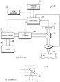
- Fig. 1 is a block diagram that schematically illustrates an ophthalmic laser surgery system 10.
- the system 10 includes a laser 14 capable of generating a pulsed laser beam 18, an energy control module 16 for controlling and varying the pulse energy of the pulsed laser beam 18, a scanner 20 for scanning the laser beam, focusing optics 28 for directing the pulsed laser beam 18 on the surface of or within the region 12 (e.g., sub-surface) of the patient's eye, an imaging system 34 for displaying a real-time digital image of the patient's eye and providing other information, a controller 22, and a user interface 32 for the operator to interact with the system.
- the system 10 also includes a beam splitter 26 and a detector 24 coupled to the controller 22 to provide a feedback control mechanism for the pulsed laser beam 18.
- the laser 14 may be, for example, an ultrashort pulse laser, e.g.
- a femtosecond laser that can output a pulsed laser beam having a pulse width in the picosecond to femtosecond range.
- some components such as the beam splitter 26 and detector 24, may be omitted; some other systems may include additional components not shown in Fig. 1 , such as range finding system, etc.
- the scanner 20 uses a pair of scanning mirrors driven by galvanometers (referred to as galvo mirrors) to angularly deflect and scan the laser beam 18.
- galvo mirrors Each galvo mirror scans the laser beam along one of the two orthogonal axes, so that the focal point 30 of the laser beam 18 may be scanned in two dimensions (e.g., the x-axis and the y-axis) in the focal plane of the system 10.
- Scanning along the third dimension i.e., moving the focal plane along the optical axis (the z-axis) may be achieved by moving the focusing optics 28 along the optical axis.
- the laser focal spot is scanned in a desired scan pattern, for example, a raster pattern, a circular pattern, a spiral pattern, a sine wave pattern, etc.
- Fig. 1A schematically illustrates a part of the scanner 20, showing one of the pair of galvo mirrors 20A, being rotatable around an axis perpendicular to the drawing sheet (as indicated by the double-arrowed arc), for scanning the laser focal spot along the x-axis.
- the input light beam is typically a collimated beam, as schematically represented by three light rays in Fig. 1A , although only one ray is shown on the output side of Fig. 1A to avoid overcrowding.
- Another galvo mirror (not shown in Fig. 1A ) scans the focal spot along the y-axis (perpendicular to the drawing sheet in this illustration).
- the controller 22 which includes at least a processor and a memory storing computer executable programs, communicates with the scanner 20 and optionally also the focusing optics 28 to direct a focal point 30 of the pulsed laser beam onto or into the eye.
- the two galvo mirrors in the scanner 20 may be controlled via a motion control system, such as a closed-loop control system.
- the galvo mirrors are relatively large and have relatively large inertia that may prevent large accelerations during execution of the laser scan.
- the galvo mirror that executes the laser scan must decelerate before the scan trajectory switches direction. The larger the moments of inertia of the galvo mirrors, the longer such deceleration or acceleration requires.
- a particular galvo mirror system has an inherent maximum acceleration that limits the scan patterns and speed that can be executed with the galvo mirror system.
- each of the two scanning mirrors that control laser delivery in the x, y dimensions is typically a flat mirror.
- a single flat mirror cannot correct wavefront aberrations that are invariably present in laser beams produced by the various optical components of the system.
- Aberrations in the laser delivery system can result in undesirably large focal spot sizes (i.e., the laser beam cannot be precisely focused to a small focal spot).
- the focal spot size also tends to depend on the x-y position of the focal spot; the focal spot typically becomes larger at locations farther away from the optical axis of the eye.
- aberrations of this type become more apparent at larger depth (from the anterior surface of the eye) of the laser treatment region.
- Bubble formation requires a threshold level of power density or pulse energy density (i.e. power or pulse energy per unit area).
- the pulse energy threshold relates directly to the minimum required energy to cut the tissue.
- Aberration increases the focal spot size and reduces energy density or power density, so higher pulse energy will be required for bubble formation.
- data show that at a target depth or 12 mm, which is still shallower than most posterior surfaces of crystalline lenses, pulse energy required for bubble formation may be many times higher for peripheral areas (e.g. 7 mm from the optical axis) than for the center areas near the optical axis.
- the laser pulse energy levels have to be set sufficiently high for the entire treatment area of the eye to ensure that peripheral regions receive a pulse energy density above the bubble formation threshold.
- energy requirement could in fact preclude certain procedures (for example, sideport incisions in some cases) because they would not be compliant with laser safety regulations.
- Document US 5 624 437 discloses a surgical laser apparatus comprising: a laser for emitting an ablating laser beam and a micromirror array for reflecting selected portions of said beam on the target.
- the micromirror array comprises a plurality of independently addressable and movable mirrors, each of said mirrors being movable between an ON position for reflecting a portion of said beam onto said target, and an OFF position for reflecting a portion of said beam away from said target.
- the present invention is directed to a laser delivery system for an ophthalmic laser system that substantially obviates one or more of the problems due to limitations and disadvantages of the related art.
- An object of the present invention is to provide an ophthalmic laser delivery system that has improved acceleration of the scan pattern by reducing the inertia of the scanning mirrors.
- Another object of the present invention is to provide an ophthalmic laser delivery system that achieves improved focusing of the laser beam.
- Another object of the present invention is to provide an ophthalmic laser delivery system that can simultaneously focus the laser beam to multiple focal spots.
- the present invention provides an ophthalmic laser delivery system for delivering a pulsed laser beam generated by a laser to a patient's eye, which includes: a laser beam scanner for reflecting an input laser beam to generate one or more output laser beams and scanning the output laser beams in two orthogonal directions, the laser beam scanner including at least one micromirror array, the micromirror array including a plurality of micromirrors forming a two-dimensional array, the plurality of micromirrors capable of being individually controlled to rotate to different angles; optics for direction the pulsed laser beam from the laser to the laser beam scanner as the input laser beam and directing the output laser beams from the laser beam scanner to the patient's eye; and a controller coupled to the laser beam scanner for controlling a rotation of each of the plurality of micromirrors of the at least one micromirror array, wherein the laser beam scanner, as controlled by the controller, cooperates with the optics to focus the pulsed laser beam to
- the laser beam scanner includes two micromirror arrays disposed in series along an optical path of the laser beam, wherein each micromirror in each micromirror array rotates around only one rotation axis, the rotation axes of all micromirrors in the same micromirror array being parallel to each other, and the rotation axes of the micromirrors in the two micromirror arrays being perpendicular to each other.
- the laser beam scanner includes a single micromirror array, wherein each micromirror in the micromirror array rotates around two orthogonal rotation axes, the respective one of the two rotation axes of all micromirrors in the micromirror array being parallel to each other.
- the controller controls the rotation angles of the plurality of micromirrors of the micromirror array to generate a focal spot of the laser beam at a specified position in the patient's eye that has a size smaller than a size of a focal spot generated at the specified position when all micromirrors of the micromirror array are rotated to identical angles.
- the rotation angles of at least some of the micromirrors are different from the rotation angles of at least some other micromirrors.
- the controller controls the rotation angles of the plurality of micromirrors of the micromirror array to simultaneously generate a plurality of focal spots of the laser beam in the patient's eye and to simultaneously scan the plurality of focal spots.
- Embodiments of the present invention provides a laser delivery system for an ophthalmic laser surgery system, in which the x-y beam scanner employs a single or two micromirror arrays micro-fabricated using MEMS (micro-electro-mechanical system) technology.
- MEMS micro-electro-mechanical system
- MEMS micromirror arrays are known and have been used in projection display systems and other technologies.
- the micromirror array is fabricated on a silicon wafer; each micromirror has a reflective surface and is suspended by torsion bars, with actuators for controlling the angle of the reflective surface relative to the fixed base on which the mirror is mounted.
- each micromirror can only rotates around one axis.
- each micromirror can rotate around two orthogonal axes independently; the corresponding rotation axes of all micromirrors in the array are parallel to each other.
- Actuation mechanisms for micromirrors include electrostatic actuation using parallel plates or comb drives, electromagnetic actuation, magnetic actuation, piezoelectric actuation, thermal bimorph actuation, etc. Such MEMS micromirror arrays and their fabrication process are generally known.
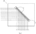
- Fig. 2 schematically illustrates a laser beam scanner 40 that employs one or two micromirror arrays 41 (only one is shown in Fig. 2 ).
- Each micromirror array 41 includes a two-dimensional array of micromirrors 41, as well as necessary drive circuitry (not shown in Fig. 2 ) to drive each micromirror.
- the beam scanner 40 replaces the scanner 20 in the laser system shown in Fig. 1 .
- the input beam impinges on the multiple individual micromirrors 42 of the micromirror array 41 and is reflected by them.
- Each mirror is controlled by its actuating mechanism to rotate along one axis or two axes.
- the size of the micromirror arrays 41 is preferably approximately the same as that of the conventional galvo mirror 20A, the size being dependent on the size of the laser beam to be reflected, and each micromirror in the array being substantially smaller than the conventional galvo mirror.
- the laser beam scanner 40 is coupled to the controller 22.
- the controller 22 in various embodiments of the present invention is different from the controller in conventional ophthalmic laser systems in that the controller in embodiments of the present invention contains computer programs to control the micromirror arrays 41 to execute various scanning modes.
- Embodiments of the present invention provide various configurations and scanning modes of the beam scanner 40, as controlled by the controller.
- the beam scanner 40 employs two micromirror arrays 41, to scan the laser beam in the x- direction and the y- direction, respectively.
- the two arrays may have identical structures.
- each micromirror array 41 each micromirrors 42 only rotates around one axis, and therefore scans the laser beam in one direction.
- the two arrays 41 are disposed in series along the optical path, but oriented such that their rotation axes are perpendicular to each other.
- all micromirrors 42 in the same array 41 are controlled to rotate synchronously in identical manners; thus, all micromirrors are parallel to each other during scanning.
- the beam is reflected by the individual micromirrors 42 of the array 41 to form a collimated output beam; as such, the micromirror arrays 41 in this embodiment do not correct the optical aberration present in the laser beam.
- the output laser beam from the scanner 40 is focused by the focusing optics 28 to a focal spot within the treatment area of the eye.
- the controller controls the rotation of the individual micromirrors of the two micromirror arrays 41 based on a predefined scan patter. As a result, the focal spot of the laser beam is scanned within the treatment area of the eye according to the predefined scan pattern.
- An advantage of the beam scanner of the first embodiment is that because each micromirror 42 has a much smaller inertia as compared to conventional galvo mirrors, a higher maximum acceleration/deceleration rate of the beam scanner can be achieved, which improves the overall scan rate.
- the beam scanner 40 employs a single micromirror array 41 in which each micromirror 42 has two independent orthogonal axes of rotation. The corresponding rotation axes of all micromirrors in the array are parallel to each other.
- a dual-axis micromirror has a fast axis and a slow axis.
- the micromirrors 42 are controlled to rotate around both axes to scan the laser beam in both the x- direction and the y- direction.
- all micromirrors 42 in the array 41 are controlled to rotate synchronously in identical manners; thus, all micromirrors are parallel to each other during scanning.
- the micromirror array 41 reflects a collimated input laser beam to form a collimated output beam; as such, the micromirror array 41 in this embodiment does not correct the optical aberration present in the laser beam.
- the output laser beam from the scanner 40 is focused by the focusing optics 28 to a focal spot within the treatment area of the eye.
- the controller controls the rotation of the individual micromirrors of the micromirror array 41 based on a predefined scan patter. As a result, the focal spot of the laser beam is scanned within the treatment area of the eye according to the predefined scan pattern.
- the beam scanner 40 employs a single micromirror array 41 in which each micromirror 42 has two axes of rotation.
- the individual micromirrors 42 in the array 41 are independently controlled to rotate to desired angles (around both axes) so as to correct the optical aberration in the laser beam.
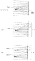
- Figs. 3 and 4 schematically illustrate the effect of aberration correction by a micromirror array.
- Fig. 3 schematically illustrates a conventional galvo mirror; it schematically depicts a converging input light beam onto a single flat galvo mirror, and the converging beam, after reflection by the flat mirror, forms a focal spot of a relatively large size, due to the optical aberration present in the input light beam caused by of upstream optical elements.
- Fig. 3 schematically illustrates a conventional galvo mirror; it schematically depicts a converging input light beam onto a single flat galvo mirror, and the converging beam, after reflection by the flat mirror, forms a focal spot of a relatively large size, due to the optical aberration present in the input light beam caused by of upstream optical elements.
- Fig. 3 schematically illustrates a conventional galvo mirror; it schematically depicts a converging input light beam onto a single flat galvo mirror, and the converging beam, after reflection by the flat mirror, forms a focal spot of
- FIG. 4 schematically illustrates the same input light beam as reflected by a micromirror array 41, in which individual micromirrors 42 are independently controlled to desired angles around both rotation axes, such that the light beam, after reflection by the micromirror array, forms a focal spot smaller than that formed when a single galvo mirror is used ( Fig. 3 ) or when all the micromirrors of the micromirror array are all parallel to each other (i.e. all rotated to the same angle).
- the micromirror array 42 can correct optical aberrations caused by other optical components in the optical system.
- Figs. 3 and 4 are only intended to illustrate the principle of aberration correction by a micromirror array; the light beams depicted in these figures do not necessarily represent the configuration of an actual laser delivery system.
- the input light to the micromirror array 41 is typically a collimated beam, which, as understood in the context of this embodiment, is a near parallel beam that may contain aberrations; the reflected beam is also a collimated beam but with reduced or corrected aberrations.
- focusing optics 28 are typically used downstream of the beam scanner 20/40 to focus the collimated light to the treatment area of the patient's eye.
- the micromirror array 41 is controlled such that it reduces the combined optical aberrations of the entire optical system, so that the focal spot size obtained at the location of the patient's eye is reduced or minimized.
- a big contributing factor to the aberrations of the beam is that the system is not telecentric, because it has to galvo mirrors, i.e. for the x and y directions. Substituting the two galvo mirrors by a micromirror array can reduce or eliminate these aberrations.
- optical aberration typically causes the focal spot size to vary depending on its location, e.g. the distance of the focal spot from the optical axis.
- the micromirror array is preferably controlled such that the focal spot size is minimized across the laser treatment area within the patient's eye.
- the required rotation angles of each micromirror that will minimize aberrations of the focal spot at each particular x-y location within the treatment area are determined.
- the required rotation angles of each micromirror may be determined for a discrete set of focal spot positions across the treatment area, and interpolated for other focal spot positions.
- the required rotation angles may be calculated by modeling the optical properties of the optical components of the system, or determined by an empirical method, e.g., by measuring the light intensity or wavefront of the actual focal spot and adjusting the rotation angles of the micromirrors to reduce the focal spot size, or obtained by a combination of the modeling and empirical approaches.
- the rotation angles obtained can be stored in a lookup table and used to perform scans.
- the required rotation angles of the micromirrors in the array are expected to be different from each other, or the required rotation angles of at least some of the micromirrors are different from the rotation angles of at least some other micromirrors.
- the required rotation angles of each micromirror as a function of the desired focal spot position may be referred to as the calibration function of the micromirror array, denoted Ci(p) where C represents the required rotation angles, i is an index of the micromirrors, and p is the location of the focal spot.
- a predefined scan pattern of the laser beam can be executed by controlling the rotation angles of each individual micromirror in the array as a function of time, based on the calibration function and the predefined laser beam scan pattern.
- the rotation angles as a function of time denoted C i (t)
- the focal spot of the laser beam is scanned over the treatment area of the eye according to the predefined scan pattern.
- the micromirror array or arrays of the beam scanner 40 are controlled to focus the laser beam simultaneously to multiple focal spots.
- Fig. 5 schematically illustrates the principle of this embodiment.
- micromirrors 42 in different parts of the array 41 are used to simultaneously focus the laser light to different locations.
- one subset of micromirrors collectively focus the laser light impinging on them to one focal point
- another subset of micromirrors collectively focus the laser light impinging on them to another focal point
- the micromirror array may be divided into these subsets of micromirrors in any suitable way.
- Fig. 5 is only intended to illustrate the principle of simultaneous focusing to multiple focal points by the micromirror array; the light beams depicted in this figure do not necessarily represent the configuration of an actual laser delivery system.
- the input light to the micromirror array 41 is typically a collimated beam; the output light of the micromirror array simultaneously contains multiple collimated beams in slightly different directions, and the multiple collimated beams are focused by the focusing optics 28 to simultaneously form multiple focal spots in the treatment area of the eye.
- the fourth embodiment may be implemented in a way that does not provide aberration correction for the focal spots, in a manner described above for the second embodiment, or it may be implemented in a way that provides aberration correction for each focal spot, in a manner described above for the third embodiment.
- the scan pattern of the pulsed laser beam is a raster pattern having multiple lines, each line corresponding to a scan in the "fast" direction of the scanner, and the multiple lines are scanned sequentially.
- multiple focal spots that are spaced apart in the "slow” direction can be scanned simultaneously in the "fast” direction to form multiple scan lines in one scan.
- Using multiple simultaneous focal spots can also make the design of the scan pattern more flexible.
- the control of the individual mirror arrays of the beam scanner 40 is performed by the controller 22.
- the controller 22 includes at least a processor and a memory storing computer readable programs which are executed to control the micromirror array or arrays of the beam scanner 40.
- a separate controller may alternatively be provided to control the micromirror arrays of the scanner.
- the laser system described above may be used for various ophthalmic procedures, such as laser cataract surgery where the laser energy is used to fragment the cataractous lens, in flap formation for LASIK (Laser Assisted In Situ Keratomileusis) where the laser energy is used to make incisions within corneal tissue to form a flap, etc.
- LASIK Laser Assisted In situ Keratomileusis
- the laser system may be used to perform corneal cuts.
- An arcuate cut for instance, is a 3-dimensional raster scan, that produces a plane that cuts the cornea.
- Other examples include primary and sideport incisions.
Landscapes
- Health & Medical Sciences (AREA)
- Physics & Mathematics (AREA)
- Optics & Photonics (AREA)
- Ophthalmology & Optometry (AREA)
- General Physics & Mathematics (AREA)
- Heart & Thoracic Surgery (AREA)
- General Health & Medical Sciences (AREA)
- Biomedical Technology (AREA)
- Surgery (AREA)
- Vascular Medicine (AREA)
- Life Sciences & Earth Sciences (AREA)
- Animal Behavior & Ethology (AREA)
- Engineering & Computer Science (AREA)
- Public Health (AREA)
- Veterinary Medicine (AREA)
- Nuclear Medicine, Radiotherapy & Molecular Imaging (AREA)
- Mechanical Optical Scanning Systems (AREA)
- Laser Surgery Devices (AREA)
- Mechanical Light Control Or Optical Switches (AREA)
Claims (7)
- Augenlaserabgabesystem (10) zum Abgeben eines gepulsten Laserstrahls (18), der durch einen Laser (14) generiert wird, an ein Auge eines Patienten, umfassend:einen Laserstrahlscanner (40) zum Reflektieren eines Eingabelaserstrahls, um einen oder mehrere Ausgabelaserstrahle zu generieren, und Scannen der Ausgabestrahle in zwei orthogonale Richtungen, wobei der Laserstrahlscanner (40) mindestens eine Mikrospiegelanordnung (41) einschließt, wobei die Mikrospiegelanordnung (41) eine Vielzahl von Mikrospiegeln (42) einschließt, die eine zweidimensionale Anordnung bilden, wobei die Vielzahl von Mikrospiegeln (42) individuell gesteuert werden kann, um auf unterschiedliche Winkel zu rotieren;Optiken (16, 20, 26, 28) zum Lenken des gepulsten Laserstrahls (18) von dem Laser (14) zu dem Laserstrahlscanner (40) als Eingabelaserstrahl und zum Lenken der Ausgabelaserstrahle von dem Laserstrahlscanner (40) zu dem Auge des Patienten; undeine Steuerung (22), die an den Laserstrahlscanner (40) gekoppelt ist, um eine Rotation von jedem aus der Vielzahl der Mikrospiegel (42) der mindestens einen Mikrospiegelanordnung (41) zu steuern,wobei der Laserstrahlscanner (40), wie er durch die Steuerung (22) gesteuert wird, mit den Optiken (16, 20, 26, 28) zusammenwirkt, um den gepulsten Laserstrahl (18) auf einen oder mehrere Brennflecken im Auge des Patienten zu fokussieren und den einen oder die mehreren Brennflecken gemäß einem vordefinierten Scanmuster zu scannen;wobei die Optiken (16, 20, 26, 28) so adaptiert sind, dass sie den gepulsten Laserstrahl (18) aus dem Laser (14) simultan zu mehreren Mikrospiegeln (42) der Mikrospiegelanordnung (41) lenken;dadurch gekennzeichnet, dass der Laserstrahlscanner (40), wie er durch die Steuerung (22) gesteuert wird, adaptiert ist, um mit den Optiken (16, 20, 22, 26) zusammenzuwirken, um reflektierte Ausgabelaserstrahle von jedem der mehreren Mikrospiegel (42) simultan auf das Auge des Patienten zu lenken, um dadurch den einen oder die mehreren Brennflecken in dem Auge des Patienten zu bilden und den einen oder die mehreren Brennflecken gemäß dem vordefinierten Scanmuster zu scannen.
- Augenlaserabgabesystem (10) nach Anspruch 1, wobei der Laserstrahlscanner (40) zwei Mikrospiegelanordnungen (41) einschließt, die in Reihe entlang eines optischen Pfads des Laserstrahls (18) angeordnet sind, wobei jeder Mikrospiegel (42) in jeder Mikrospiegelanordnung (41) so adaptiert ist, dass er um nur eine Rotationsachse rotiert, wobei die Rotationsachsen aller Mikrospiegel (42) in derselben Mikrospiegelanordnung (41) parallel zueinander sind, und wobei die Rotationsachsen der Mikrospiegel in den beiden Mikrospiegelanordnungen (41) senkrecht zueinander sind.
- Augenlaserabgabesystem (10) nach Anspruch 1, wobei der Laserstrahlscanner (40) eine einzige Mikrospiegelanordnung (41) einschließt, wobei jeder Mikrospiegel (42) in der Mikrospiegelanordnung (41) so adaptiert ist, dass er um zwei orthogonale Rotationsachsen rotiert, wobei die jeweils eine der beiden Rotationsachsen von allen Mikrospiegeln (42) in der Mikrospiegelanordnung (41) parallel zueinander sind.
- Augenlaserabgabesystem (10) nach Anspruch 3, wobei die Steuerung (22) so adaptiert ist, dass die Rotationswinkel der Vielzahl von Mikrospiegeln (42) der Mikrospiegelanordnung (41) gesteuert werden, um einen Brennfleck des Laserstrahls (18) an einer spezifizierten Position in dem Auge des Patienten zu generieren, welcher eine kleinere Größe als eine Größe des Brennflecks hat, der an der spezifizierten Position generiert wird, wenn alle Mikrospiegel (42) der Mikrospiegelanordnung (41) auf identische Winkel rotiert werden.
- Augenlaserabgabesystem (10) nach Anspruch 4, wobei die Rotationswinkel von mindestens einigen der Mikrospiegel (42) für jede gegebene Brennfleckposition in dem Scanmuster sich von den Rotationswinkeln von mindestens einigen anderen Mikrospiegeln (42) unterscheiden.
- Augenlaserabgabesystem (10) nach Anspruch 3, wobei die Steuerung (22) so adaptiert ist, dass sie die Rotationswinkel der Vielzahl von Mikrospiegeln (42) der Mikrospiegelanordnung (41) steuert, um simultan eine Vielzahl von Brennflecken des Laserstrahls (18) im Auge des Patienten zu generieren und simultan die Vielzahl von Brennflecken zu scannen.
- Augenlaserabgabesystem (10) nach Anspruch 1, wobei jede der mindestens einen Mikrospiegelanordnung (41) eine MEMS- (mikroelektromechanisches System)-Struktur ist.
Applications Claiming Priority (2)
| Application Number | Priority Date | Filing Date | Title |
|---|---|---|---|
| US201662413370P | 2016-10-26 | 2016-10-26 | |
| PCT/US2017/058360 WO2018081311A1 (en) | 2016-10-26 | 2017-10-25 | Ophthalmic laser delivery apparatus using mems micromirror arrays for scanning and focusing laser beam |
Publications (2)
| Publication Number | Publication Date |
|---|---|
| EP3531992A1 EP3531992A1 (de) | 2019-09-04 |
| EP3531992B1 true EP3531992B1 (de) | 2020-11-25 |
Family
ID=60269972
Family Applications (1)
| Application Number | Title | Priority Date | Filing Date |
|---|---|---|---|
| EP17795160.5A Active EP3531992B1 (de) | 2016-10-26 | 2017-10-25 | Augenlaserführungsvorrichtung mit mems-mikrospiegelanordnungen zur abtastung und fokussierung eines laserstrahls |
Country Status (5)
| Country | Link |
|---|---|
| US (3) | US10786389B2 (de) |
| EP (1) | EP3531992B1 (de) |
| AU (1) | AU2017350884B2 (de) |
| CA (1) | CA3041662A1 (de) |
| WO (1) | WO2018081311A1 (de) |
Families Citing this family (4)
| Publication number | Priority date | Publication date | Assignee | Title |
|---|---|---|---|---|
| CN113382674A (zh) | 2018-11-28 | 2021-09-10 | 布罗德斯普特成像公司 | 后段的超宽视野成像系统 |
| US11896528B2 (en) * | 2019-08-15 | 2024-02-13 | Norlase Aps | Scanning laser ophthalmic treatment system and method of operation |
| CN111283335B (zh) * | 2020-03-24 | 2022-02-22 | 宁波大学 | 激光显微切割装置及方法 |
| CN114145908B (zh) * | 2021-11-05 | 2023-03-24 | 华中科技大学 | 一种使用聚焦线光斑产生曲面扫描面的方法和装置 |
Family Cites Families (25)
| Publication number | Priority date | Publication date | Assignee | Title |
|---|---|---|---|---|
| US5984916A (en) | 1993-04-20 | 1999-11-16 | Lai; Shui T. | Ophthalmic surgical laser and method |
| US5743902A (en) | 1995-01-23 | 1998-04-28 | Coherent, Inc. | Hand-held laser scanner |
| US6454761B1 (en) | 1995-01-30 | 2002-09-24 | Philip D. Freedman | Laser surgery device and method |
| US5624437A (en) * | 1995-03-28 | 1997-04-29 | Freeman; Jerre M. | High resolution, high speed, programmable laser beam modulating apparatus for microsurgery |
| US5720894A (en) | 1996-01-11 | 1998-02-24 | The Regents Of The University Of California | Ultrashort pulse high repetition rate laser system for biological tissue processing |
| US7655002B2 (en) | 1996-03-21 | 2010-02-02 | Second Sight Laser Technologies, Inc. | Lenticular refractive surgery of presbyopia, other refractive errors, and cataract retardation |
| US6019472A (en) | 1997-05-12 | 2000-02-01 | Koester; Charles J. | Contact lens element for examination or treatment of ocular tissues |
| US8262646B2 (en) | 2006-01-20 | 2012-09-11 | Lensar, Inc. | System and method for providing the shaped structural weakening of the human lens with a laser |
| US20110319875A1 (en) | 2007-01-19 | 2011-12-29 | Frieder Loesel | Apparatus and Method for Morphing a Three-Dimensional Target Surface into a Two-Dimensional Image for Use in Guiding a Laser Beam in Ocular Surgery |
| DE102007028042B3 (de) | 2007-06-14 | 2008-08-07 | Universität Zu Lübeck | Verfahren zur Laserbearbeitung transparenter Materialien |
| US7717907B2 (en) | 2007-12-17 | 2010-05-18 | Technolas Perfect Vision Gmbh | Method for intrastromal refractive surgery |
| US8382745B2 (en) | 2009-07-24 | 2013-02-26 | Lensar, Inc. | Laser system and method for astigmatic corrections in association with cataract treatment |
| US8414564B2 (en) | 2010-02-18 | 2013-04-09 | Alcon Lensx, Inc. | Optical coherence tomographic system for ophthalmic surgery |
| US8845624B2 (en) | 2010-06-25 | 2014-09-30 | Alcon LexSx, Inc. | Adaptive patient interface |
| DE102011001083B4 (de) * | 2011-03-04 | 2015-11-05 | Eyesight & Vision Gmbh | Projektorvorrichtung mit Selbstkorrekturfunktion sowie Medizingerät mit der Projektorvorrichtung |
| US20140088573A1 (en) * | 2011-03-04 | 2014-03-27 | Eyesight & Vision Gmbh | Projector device, and medical device comprising the projector device |
| ES2415555B2 (es) | 2011-05-20 | 2014-07-09 | Medlumics, S.L. | Dispositivo de barrido para interferometría de baja coherencia. |
| JP5956884B2 (ja) * | 2012-09-13 | 2016-07-27 | 株式会社トプコン | レーザ治療装置 |
| US20150085254A1 (en) * | 2013-09-26 | 2015-03-26 | Topcon Medical Laser Systems, Inc. | Micro-Display Based Slit Lamp Illumination System |
| RU2675688C2 (ru) * | 2013-12-23 | 2018-12-21 | Новартис Аг | Хирургическая система визуализации oct широкого поля обзора без использования микроскопа |
| JP6498692B2 (ja) * | 2014-03-26 | 2019-04-10 | オプティメディカ コーポレイション | 共焦点レーザ眼球手術システム |
| US9724239B2 (en) * | 2014-07-14 | 2017-08-08 | Novartis Ag | Movable wide-angle ophthalmic surgical system |
| US20160183782A1 (en) * | 2014-12-29 | 2016-06-30 | Novartis Ag | Oct surgical visualization system with macular contact lens |
| US20190314194A1 (en) * | 2016-08-12 | 2019-10-17 | Alex Artsyukhovich | A surgical laser capsulorhexis system and patient interface lens accessory |
| CA3079936A1 (en) * | 2017-12-12 | 2019-06-20 | Alcon Inc. | Combined near infrared imaging and visible imaging in a compact microscope stack |
-
2017
- 2017-10-25 US US15/793,851 patent/US10786389B2/en active Active
- 2017-10-25 EP EP17795160.5A patent/EP3531992B1/de active Active
- 2017-10-25 WO PCT/US2017/058360 patent/WO2018081311A1/en unknown
- 2017-10-25 AU AU2017350884A patent/AU2017350884B2/en not_active Ceased
- 2017-10-25 CA CA3041662A patent/CA3041662A1/en active Pending
-
2020
- 2020-09-24 US US17/031,793 patent/US11786403B2/en active Active
-
2023
- 2023-10-13 US US18/487,038 patent/US20240033127A1/en active Pending
Non-Patent Citations (1)
| Title |
|---|
| None * |
Also Published As
| Publication number | Publication date |
|---|---|
| US20180110651A1 (en) | 2018-04-26 |
| US20240033127A1 (en) | 2024-02-01 |
| AU2017350884B2 (en) | 2022-08-11 |
| US20210015667A1 (en) | 2021-01-21 |
| US11786403B2 (en) | 2023-10-17 |
| EP3531992A1 (de) | 2019-09-04 |
| CA3041662A1 (en) | 2018-05-03 |
| AU2017350884A1 (en) | 2019-05-23 |
| WO2018081311A1 (en) | 2018-05-03 |
| US10786389B2 (en) | 2020-09-29 |
Similar Documents
| Publication | Publication Date | Title |
|---|---|---|
| US11786403B2 (en) | Ophthalmic laser delivery apparatus using mems micromirror arrays for scanning and focusing laser beam | |
| US11857462B2 (en) | Laser eye surgery system | |
| US20240009033A1 (en) | Apparatus for working on eye tissue by means of a pulsed laser beam | |
| US11554045B2 (en) | Device for processing eye tissue by means of a pulsed laser beam | |
| EP3122298B1 (de) | Automatisierte kalibrierung eines lasersystems und tomografiesystem mit fluoreszierender abbildung von abtastmustern | |
| US9566190B2 (en) | Device for processing eye tissue by means of a pulsed laser beam | |
| US10092446B2 (en) | Laser scanner apparatus and method | |
| EP2837368A2 (de) | Ophthalmische Laseroperationsvorrichtung | |
| US20230201039A1 (en) | Ophthalmological Device for Processing a Curved Treatment Face | |
| US8992020B2 (en) | Device for processing eye tissue by means of a pulsed laser beam | |
| US20230015597A1 (en) | Ophthalmological Device For Processing A Curved Treatment Face | |
| JP2013078398A (ja) | 眼科用レーザ手術装置 | |
| US20240197532A1 (en) | Lasik corneal flap cutting patterns for bubble management | |
| US20220331163A1 (en) | Ophthalmological device for refractive correction of a cornea | |
| WO2014074934A2 (en) | Laser scanner apparatus and method |
Legal Events
| Date | Code | Title | Description |
|---|---|---|---|
| STAA | Information on the status of an ep patent application or granted ep patent |
Free format text: STATUS: UNKNOWN |
|
| STAA | Information on the status of an ep patent application or granted ep patent |
Free format text: STATUS: THE INTERNATIONAL PUBLICATION HAS BEEN MADE |
|
| PUAI | Public reference made under article 153(3) epc to a published international application that has entered the european phase |
Free format text: ORIGINAL CODE: 0009012 |
|
| STAA | Information on the status of an ep patent application or granted ep patent |
Free format text: STATUS: REQUEST FOR EXAMINATION WAS MADE |
|
| 17P | Request for examination filed |
Effective date: 20190429 |
|
| AK | Designated contracting states |
Kind code of ref document: A1 Designated state(s): AL AT BE BG CH CY CZ DE DK EE ES FI FR GB GR HR HU IE IS IT LI LT LU LV MC MK MT NL NO PL PT RO RS SE SI SK SM TR |
|
| AX | Request for extension of the european patent |
Extension state: BA ME |
|
| DAV | Request for validation of the european patent (deleted) | ||
| DAX | Request for extension of the european patent (deleted) | ||
| GRAP | Despatch of communication of intention to grant a patent |
Free format text: ORIGINAL CODE: EPIDOSNIGR1 |
|
| STAA | Information on the status of an ep patent application or granted ep patent |
Free format text: STATUS: GRANT OF PATENT IS INTENDED |
|
| RIC1 | Information provided on ipc code assigned before grant |
Ipc: A61F 9/008 20060101AFI20200504BHEP Ipc: G02B 26/08 20060101ALI20200504BHEP Ipc: G02B 26/10 20060101ALI20200504BHEP Ipc: G02B 27/18 20060101ALI20200504BHEP |
|
| INTG | Intention to grant announced |
Effective date: 20200604 |
|
| RAP1 | Party data changed (applicant data changed or rights of an application transferred) |
Owner name: AMO DEVELOPMENT, LLC |
|
| GRAS | Grant fee paid |
Free format text: ORIGINAL CODE: EPIDOSNIGR3 |
|
| GRAA | (expected) grant |
Free format text: ORIGINAL CODE: 0009210 |
|
| STAA | Information on the status of an ep patent application or granted ep patent |
Free format text: STATUS: THE PATENT HAS BEEN GRANTED |
|
| AK | Designated contracting states |
Kind code of ref document: B1 Designated state(s): AL AT BE BG CH CY CZ DE DK EE ES FI FR GB GR HR HU IE IS IT LI LT LU LV MC MK MT NL NO PL PT RO RS SE SI SK SM TR |
|
| REG | Reference to a national code |
Ref country code: GB Ref legal event code: FG4D |
|
| REG | Reference to a national code |
Ref country code: CH Ref legal event code: EP Ref country code: CH Ref legal event code: NV Representative=s name: E. BLUM AND CO. AG PATENT- UND MARKENANWAELTE , CH |
|
| REG | Reference to a national code |
Ref country code: AT Ref legal event code: REF Ref document number: 1337429 Country of ref document: AT Kind code of ref document: T Effective date: 20201215 |
|
| REG | Reference to a national code |
Ref country code: DE Ref legal event code: R096 Ref document number: 602017028455 Country of ref document: DE |
|
| REG | Reference to a national code |
Ref country code: IE Ref legal event code: FG4D |
|
| REG | Reference to a national code |
Ref country code: NL Ref legal event code: FP |
|
| REG | Reference to a national code |
Ref country code: AT Ref legal event code: MK05 Ref document number: 1337429 Country of ref document: AT Kind code of ref document: T Effective date: 20201125 |
|
| PG25 | Lapsed in a contracting state [announced via postgrant information from national office to epo] |
Ref country code: FI Free format text: LAPSE BECAUSE OF FAILURE TO SUBMIT A TRANSLATION OF THE DESCRIPTION OR TO PAY THE FEE WITHIN THE PRESCRIBED TIME-LIMIT Effective date: 20201125 Ref country code: RS Free format text: LAPSE BECAUSE OF FAILURE TO SUBMIT A TRANSLATION OF THE DESCRIPTION OR TO PAY THE FEE WITHIN THE PRESCRIBED TIME-LIMIT Effective date: 20201125 Ref country code: PT Free format text: LAPSE BECAUSE OF FAILURE TO SUBMIT A TRANSLATION OF THE DESCRIPTION OR TO PAY THE FEE WITHIN THE PRESCRIBED TIME-LIMIT Effective date: 20210325 Ref country code: GR Free format text: LAPSE BECAUSE OF FAILURE TO SUBMIT A TRANSLATION OF THE DESCRIPTION OR TO PAY THE FEE WITHIN THE PRESCRIBED TIME-LIMIT Effective date: 20210226 Ref country code: NO Free format text: LAPSE BECAUSE OF FAILURE TO SUBMIT A TRANSLATION OF THE DESCRIPTION OR TO PAY THE FEE WITHIN THE PRESCRIBED TIME-LIMIT Effective date: 20210225 |
|
| PG25 | Lapsed in a contracting state [announced via postgrant information from national office to epo] |
Ref country code: BG Free format text: LAPSE BECAUSE OF FAILURE TO SUBMIT A TRANSLATION OF THE DESCRIPTION OR TO PAY THE FEE WITHIN THE PRESCRIBED TIME-LIMIT Effective date: 20210225 Ref country code: SE Free format text: LAPSE BECAUSE OF FAILURE TO SUBMIT A TRANSLATION OF THE DESCRIPTION OR TO PAY THE FEE WITHIN THE PRESCRIBED TIME-LIMIT Effective date: 20201125 Ref country code: PL Free format text: LAPSE BECAUSE OF FAILURE TO SUBMIT A TRANSLATION OF THE DESCRIPTION OR TO PAY THE FEE WITHIN THE PRESCRIBED TIME-LIMIT Effective date: 20201125 Ref country code: IS Free format text: LAPSE BECAUSE OF FAILURE TO SUBMIT A TRANSLATION OF THE DESCRIPTION OR TO PAY THE FEE WITHIN THE PRESCRIBED TIME-LIMIT Effective date: 20210325 Ref country code: LV Free format text: LAPSE BECAUSE OF FAILURE TO SUBMIT A TRANSLATION OF THE DESCRIPTION OR TO PAY THE FEE WITHIN THE PRESCRIBED TIME-LIMIT Effective date: 20201125 Ref country code: AT Free format text: LAPSE BECAUSE OF FAILURE TO SUBMIT A TRANSLATION OF THE DESCRIPTION OR TO PAY THE FEE WITHIN THE PRESCRIBED TIME-LIMIT Effective date: 20201125 |
|
| REG | Reference to a national code |
Ref country code: LT Ref legal event code: MG9D |
|
| PG25 | Lapsed in a contracting state [announced via postgrant information from national office to epo] |
Ref country code: HR Free format text: LAPSE BECAUSE OF FAILURE TO SUBMIT A TRANSLATION OF THE DESCRIPTION OR TO PAY THE FEE WITHIN THE PRESCRIBED TIME-LIMIT Effective date: 20201125 |
|
| PG25 | Lapsed in a contracting state [announced via postgrant information from national office to epo] |
Ref country code: EE Free format text: LAPSE BECAUSE OF FAILURE TO SUBMIT A TRANSLATION OF THE DESCRIPTION OR TO PAY THE FEE WITHIN THE PRESCRIBED TIME-LIMIT Effective date: 20201125 Ref country code: CZ Free format text: LAPSE BECAUSE OF FAILURE TO SUBMIT A TRANSLATION OF THE DESCRIPTION OR TO PAY THE FEE WITHIN THE PRESCRIBED TIME-LIMIT Effective date: 20201125 Ref country code: LT Free format text: LAPSE BECAUSE OF FAILURE TO SUBMIT A TRANSLATION OF THE DESCRIPTION OR TO PAY THE FEE WITHIN THE PRESCRIBED TIME-LIMIT Effective date: 20201125 Ref country code: SM Free format text: LAPSE BECAUSE OF FAILURE TO SUBMIT A TRANSLATION OF THE DESCRIPTION OR TO PAY THE FEE WITHIN THE PRESCRIBED TIME-LIMIT Effective date: 20201125 Ref country code: RO Free format text: LAPSE BECAUSE OF FAILURE TO SUBMIT A TRANSLATION OF THE DESCRIPTION OR TO PAY THE FEE WITHIN THE PRESCRIBED TIME-LIMIT Effective date: 20201125 Ref country code: SK Free format text: LAPSE BECAUSE OF FAILURE TO SUBMIT A TRANSLATION OF THE DESCRIPTION OR TO PAY THE FEE WITHIN THE PRESCRIBED TIME-LIMIT Effective date: 20201125 |
|
| REG | Reference to a national code |
Ref country code: DE Ref legal event code: R097 Ref document number: 602017028455 Country of ref document: DE |
|
| PG25 | Lapsed in a contracting state [announced via postgrant information from national office to epo] |
Ref country code: DK Free format text: LAPSE BECAUSE OF FAILURE TO SUBMIT A TRANSLATION OF THE DESCRIPTION OR TO PAY THE FEE WITHIN THE PRESCRIBED TIME-LIMIT Effective date: 20201125 |
|
| PLBE | No opposition filed within time limit |
Free format text: ORIGINAL CODE: 0009261 |
|
| STAA | Information on the status of an ep patent application or granted ep patent |
Free format text: STATUS: NO OPPOSITION FILED WITHIN TIME LIMIT |
|
| PG25 | Lapsed in a contracting state [announced via postgrant information from national office to epo] |
Ref country code: AL Free format text: LAPSE BECAUSE OF FAILURE TO SUBMIT A TRANSLATION OF THE DESCRIPTION OR TO PAY THE FEE WITHIN THE PRESCRIBED TIME-LIMIT Effective date: 20201125 Ref country code: IT Free format text: LAPSE BECAUSE OF FAILURE TO SUBMIT A TRANSLATION OF THE DESCRIPTION OR TO PAY THE FEE WITHIN THE PRESCRIBED TIME-LIMIT Effective date: 20201125 |
|
| 26N | No opposition filed |
Effective date: 20210826 |
|
| PG25 | Lapsed in a contracting state [announced via postgrant information from national office to epo] |
Ref country code: SI Free format text: LAPSE BECAUSE OF FAILURE TO SUBMIT A TRANSLATION OF THE DESCRIPTION OR TO PAY THE FEE WITHIN THE PRESCRIBED TIME-LIMIT Effective date: 20201125 |
|
| PG25 | Lapsed in a contracting state [announced via postgrant information from national office to epo] |
Ref country code: ES Free format text: LAPSE BECAUSE OF FAILURE TO SUBMIT A TRANSLATION OF THE DESCRIPTION OR TO PAY THE FEE WITHIN THE PRESCRIBED TIME-LIMIT Effective date: 20201125 |
|
| PG25 | Lapsed in a contracting state [announced via postgrant information from national office to epo] |
Ref country code: IS Free format text: LAPSE BECAUSE OF FAILURE TO SUBMIT A TRANSLATION OF THE DESCRIPTION OR TO PAY THE FEE WITHIN THE PRESCRIBED TIME-LIMIT Effective date: 20210325 |
|
| REG | Reference to a national code |
Ref country code: BE Ref legal event code: MM Effective date: 20211031 |
|
| PG25 | Lapsed in a contracting state [announced via postgrant information from national office to epo] |
Ref country code: MC Free format text: LAPSE BECAUSE OF FAILURE TO SUBMIT A TRANSLATION OF THE DESCRIPTION OR TO PAY THE FEE WITHIN THE PRESCRIBED TIME-LIMIT Effective date: 20201125 |
|
| PG25 | Lapsed in a contracting state [announced via postgrant information from national office to epo] |
Ref country code: LU Free format text: LAPSE BECAUSE OF NON-PAYMENT OF DUE FEES Effective date: 20211025 Ref country code: BE Free format text: LAPSE BECAUSE OF NON-PAYMENT OF DUE FEES Effective date: 20211031 |
|
| PG25 | Lapsed in a contracting state [announced via postgrant information from national office to epo] |
Ref country code: IE Free format text: LAPSE BECAUSE OF NON-PAYMENT OF DUE FEES Effective date: 20211025 |
|
| PGFP | Annual fee paid to national office [announced via postgrant information from national office to epo] |
Ref country code: NL Payment date: 20220916 Year of fee payment: 6 Ref country code: GB Payment date: 20220901 Year of fee payment: 6 |
|
| PGFP | Annual fee paid to national office [announced via postgrant information from national office to epo] |
Ref country code: CH Payment date: 20221010 Year of fee payment: 6 |
|
| PG25 | Lapsed in a contracting state [announced via postgrant information from national office to epo] |
Ref country code: CY Free format text: LAPSE BECAUSE OF FAILURE TO SUBMIT A TRANSLATION OF THE DESCRIPTION OR TO PAY THE FEE WITHIN THE PRESCRIBED TIME-LIMIT Effective date: 20201125 |
|
| PG25 | Lapsed in a contracting state [announced via postgrant information from national office to epo] |
Ref country code: HU Free format text: LAPSE BECAUSE OF FAILURE TO SUBMIT A TRANSLATION OF THE DESCRIPTION OR TO PAY THE FEE WITHIN THE PRESCRIBED TIME-LIMIT; INVALID AB INITIO Effective date: 20171025 |
|
| PGFP | Annual fee paid to national office [announced via postgrant information from national office to epo] |
Ref country code: FR Payment date: 20230911 Year of fee payment: 7 |
|
| PGFP | Annual fee paid to national office [announced via postgrant information from national office to epo] |
Ref country code: DE Payment date: 20230830 Year of fee payment: 7 |
|
| PG25 | Lapsed in a contracting state [announced via postgrant information from national office to epo] |
Ref country code: MK Free format text: LAPSE BECAUSE OF FAILURE TO SUBMIT A TRANSLATION OF THE DESCRIPTION OR TO PAY THE FEE WITHIN THE PRESCRIBED TIME-LIMIT Effective date: 20201125 |
|
| REG | Reference to a national code |
Ref country code: CH Ref legal event code: PL |
|
| REG | Reference to a national code |
Ref country code: NL Ref legal event code: MM Effective date: 20231101 |
|
| GBPC | Gb: european patent ceased through non-payment of renewal fee |
Effective date: 20231025 |
|
| PG25 | Lapsed in a contracting state [announced via postgrant information from national office to epo] |
Ref country code: GB Free format text: LAPSE BECAUSE OF NON-PAYMENT OF DUE FEES Effective date: 20231025 |
|
| PG25 | Lapsed in a contracting state [announced via postgrant information from national office to epo] |
Ref country code: NL Free format text: LAPSE BECAUSE OF NON-PAYMENT OF DUE FEES Effective date: 20231101 Ref country code: CH Free format text: LAPSE BECAUSE OF NON-PAYMENT OF DUE FEES Effective date: 20231031 |
|
| PG25 | Lapsed in a contracting state [announced via postgrant information from national office to epo] |
Ref country code: NL Free format text: LAPSE BECAUSE OF NON-PAYMENT OF DUE FEES Effective date: 20231101 Ref country code: GB Free format text: LAPSE BECAUSE OF NON-PAYMENT OF DUE FEES Effective date: 20231025 Ref country code: CH Free format text: LAPSE BECAUSE OF NON-PAYMENT OF DUE FEES Effective date: 20231031 |