EP3531789B1 - Dispositif de communications pour l'amélioration de la transmission de messages d'accès aléatoire - Google Patents
Dispositif de communications pour l'amélioration de la transmission de messages d'accès aléatoire Download PDFInfo
- Publication number
- EP3531789B1 EP3531789B1 EP19161706.7A EP19161706A EP3531789B1 EP 3531789 B1 EP3531789 B1 EP 3531789B1 EP 19161706 A EP19161706 A EP 19161706A EP 3531789 B1 EP3531789 B1 EP 3531789B1
- Authority
- EP
- European Patent Office
- Prior art keywords
- random access
- network
- network element
- communications device
- message
- Prior art date
- Legal status (The legal status is an assumption and is not a legal conclusion. Google has not performed a legal analysis and makes no representation as to the accuracy of the status listed.)
- Active
Links
- 238000004891 communication Methods 0.000 title claims description 44
- 230000005540 biological transmission Effects 0.000 title description 67
- 230000004044 response Effects 0.000 claims description 66
- 238000010295 mobile communication Methods 0.000 claims description 14
- 230000000694 effects Effects 0.000 claims description 2
- 238000001514 detection method Methods 0.000 claims 4
- 238000000034 method Methods 0.000 description 50
- 238000010586 diagram Methods 0.000 description 19
- 238000013459 approach Methods 0.000 description 11
- 239000000969 carrier Substances 0.000 description 9
- 230000008901 benefit Effects 0.000 description 6
- 230000001934 delay Effects 0.000 description 6
- 230000008569 process Effects 0.000 description 6
- 230000011664 signaling Effects 0.000 description 6
- 238000013468 resource allocation Methods 0.000 description 5
- 230000003111 delayed effect Effects 0.000 description 4
- 230000000875 corresponding effect Effects 0.000 description 3
- 230000001419 dependent effect Effects 0.000 description 3
- 230000006870 function Effects 0.000 description 3
- 230000009471 action Effects 0.000 description 2
- 230000006399 behavior Effects 0.000 description 2
- 238000004364 calculation method Methods 0.000 description 2
- 238000009826 distribution Methods 0.000 description 2
- 230000007774 longterm Effects 0.000 description 2
- 238000012545 processing Methods 0.000 description 2
- 101000741965 Homo sapiens Inactive tyrosine-protein kinase PRAG1 Proteins 0.000 description 1
- 102100038659 Inactive tyrosine-protein kinase PRAG1 Human genes 0.000 description 1
- 101150039363 SIB2 gene Proteins 0.000 description 1
- 230000002411 adverse Effects 0.000 description 1
- 230000003466 anti-cipated effect Effects 0.000 description 1
- 230000009286 beneficial effect Effects 0.000 description 1
- 230000002596 correlated effect Effects 0.000 description 1
- 238000011161 development Methods 0.000 description 1
- 230000005611 electricity Effects 0.000 description 1
- 238000005516 engineering process Methods 0.000 description 1
- 230000000977 initiatory effect Effects 0.000 description 1
- 230000002045 lasting effect Effects 0.000 description 1
- 238000007726 management method Methods 0.000 description 1
- 230000000116 mitigating effect Effects 0.000 description 1
- 238000012986 modification Methods 0.000 description 1
- 230000004048 modification Effects 0.000 description 1
- 230000002123 temporal effect Effects 0.000 description 1
- 230000001960 triggered effect Effects 0.000 description 1
- 238000009827 uniform distribution Methods 0.000 description 1
- XLYOFNOQVPJJNP-UHFFFAOYSA-N water Substances O XLYOFNOQVPJJNP-UHFFFAOYSA-N 0.000 description 1
Images


Classifications
-
- H—ELECTRICITY
- H04—ELECTRIC COMMUNICATION TECHNIQUE
- H04W—WIRELESS COMMUNICATION NETWORKS
- H04W28/00—Network traffic management; Network resource management
- H04W28/02—Traffic management, e.g. flow control or congestion control
- H04W28/0205—Traffic management, e.g. flow control or congestion control at the air interface
-
- H—ELECTRICITY
- H04—ELECTRIC COMMUNICATION TECHNIQUE
- H04W—WIRELESS COMMUNICATION NETWORKS
- H04W28/00—Network traffic management; Network resource management
- H04W28/02—Traffic management, e.g. flow control or congestion control
- H04W28/0215—Traffic management, e.g. flow control or congestion control based on user or device properties, e.g. MTC-capable devices
- H04W28/0221—Traffic management, e.g. flow control or congestion control based on user or device properties, e.g. MTC-capable devices power availability or consumption
-
- H—ELECTRICITY
- H04—ELECTRIC COMMUNICATION TECHNIQUE
- H04W—WIRELESS COMMUNICATION NETWORKS
- H04W74/00—Wireless channel access
- H04W74/002—Transmission of channel access control information
-
- H—ELECTRICITY
- H04—ELECTRIC COMMUNICATION TECHNIQUE
- H04W—WIRELESS COMMUNICATION NETWORKS
- H04W74/00—Wireless channel access
- H04W74/002—Transmission of channel access control information
- H04W74/004—Transmission of channel access control information in the uplink, i.e. towards network
-
- H—ELECTRICITY
- H04—ELECTRIC COMMUNICATION TECHNIQUE
- H04W—WIRELESS COMMUNICATION NETWORKS
- H04W74/00—Wireless channel access
- H04W74/08—Non-scheduled access, e.g. ALOHA
- H04W74/0833—Random access procedures, e.g. with 4-step access
-
- H—ELECTRICITY
- H04—ELECTRIC COMMUNICATION TECHNIQUE
- H04W—WIRELESS COMMUNICATION NETWORKS
- H04W74/00—Wireless channel access
- H04W74/08—Non-scheduled access, e.g. ALOHA
- H04W74/0833—Random access procedures, e.g. with 4-step access
- H04W74/0841—Random access procedures, e.g. with 4-step access with collision treatment
- H04W74/085—Random access procedures, e.g. with 4-step access with collision treatment collision avoidance
-
- H—ELECTRICITY
- H04—ELECTRIC COMMUNICATION TECHNIQUE
- H04W—WIRELESS COMMUNICATION NETWORKS
- H04W56/00—Synchronisation arrangements
- H04W56/0005—Synchronisation arrangements synchronizing of arrival of multiple uplinks
-
- H—ELECTRICITY
- H04—ELECTRIC COMMUNICATION TECHNIQUE
- H04W—WIRELESS COMMUNICATION NETWORKS
- H04W56/00—Synchronisation arrangements
- H04W56/001—Synchronization between nodes
- H04W56/0015—Synchronization between nodes one node acting as a reference for the others
-
- H—ELECTRICITY
- H04—ELECTRIC COMMUNICATION TECHNIQUE
- H04W—WIRELESS COMMUNICATION NETWORKS
- H04W56/00—Synchronisation arrangements
- H04W56/004—Synchronisation arrangements compensating for timing error of reception due to propagation delay
- H04W56/0045—Synchronisation arrangements compensating for timing error of reception due to propagation delay compensating for timing error by altering transmission time
-
- H—ELECTRICITY
- H04—ELECTRIC COMMUNICATION TECHNIQUE
- H04W—WIRELESS COMMUNICATION NETWORKS
- H04W72/00—Local resource management
- H04W72/20—Control channels or signalling for resource management
- H04W72/21—Control channels or signalling for resource management in the uplink direction of a wireless link, i.e. towards the network
-
- H—ELECTRICITY
- H04—ELECTRIC COMMUNICATION TECHNIQUE
- H04W—WIRELESS COMMUNICATION NETWORKS
- H04W72/00—Local resource management
- H04W72/20—Control channels or signalling for resource management
- H04W72/23—Control channels or signalling for resource management in the downlink direction of a wireless link, i.e. towards a terminal
-
- Y—GENERAL TAGGING OF NEW TECHNOLOGICAL DEVELOPMENTS; GENERAL TAGGING OF CROSS-SECTIONAL TECHNOLOGIES SPANNING OVER SEVERAL SECTIONS OF THE IPC; TECHNICAL SUBJECTS COVERED BY FORMER USPC CROSS-REFERENCE ART COLLECTIONS [XRACs] AND DIGESTS
- Y04—INFORMATION OR COMMUNICATION TECHNOLOGIES HAVING AN IMPACT ON OTHER TECHNOLOGY AREAS
- Y04S—SYSTEMS INTEGRATING TECHNOLOGIES RELATED TO POWER NETWORK OPERATION, COMMUNICATION OR INFORMATION TECHNOLOGIES FOR IMPROVING THE ELECTRICAL POWER GENERATION, TRANSMISSION, DISTRIBUTION, MANAGEMENT OR USAGE, i.e. SMART GRIDS
- Y04S20/00—Management or operation of end-user stationary applications or the last stages of power distribution; Controlling, monitoring or operating thereof
- Y04S20/30—Smart metering, e.g. specially adapted for remote reading
Definitions
- the present invention relates to communications devices for communicating via a mobile communications network, and circuitry.
- Third and fourth generation mobile telecommunication systems such as those based on the 3GPP defined UMTS and Long Term Evolution (LTE) architecture are able to support more sophisticated services than simple voice and messaging services offered by previous generations of mobile telecommunication systems.
- LTE Long Term Evolution
- third and fourth generation networks are therefore strong and the coverage area of these networks, i.e. geographic locations where access to the networks is possible, is expected to increase rapidly.
- MTC machine type communication
- smart meters which, for example, are located in a customer's house and periodically transmit information back to a central MTC server data relating to the customers consumption of a utility such as gas, water, electricity and so on.
- an MTC-type terminal Whilst it can be convenient for a terminal such as an MTC type terminal to take advantage of the wide coverage area provided by a third or fourth generation mobile telecommunication network there are at present disadvantages. Unlike a conventional third or fourth generation mobile terminal such as a smartphone, an MTC-type terminal is preferably relatively simple and inexpensive. The type of functions performed by the MTC-type terminal (e.g. collecting and reporting back data) do not require particularly complex processing to perform.
- third and fourth generation mobile telecommunication networks typically employ advanced data modulation techniques on the radio interface which can require more complex and expensive radio transceivers to implement. It is usually justified to include such complex transceivers in a smartphone as a smartphone will typically require a powerful processor to perform typical smartphone type functions.
- LTE type networks Whilst it can be convenient for a terminal such as an MTC type terminal to take advantage of the wide coverage area provided by a third or fourth generation mobile telecommunication network there are at present disadvantages. Unlike a conventional third or fourth generation mobile terminal such as a smartphone, an
- EP 1 035 745 A1 relates to an apparatus for transmitting and receiving signals in a wireless telecommunication system and to a method for transmitting random access bursts in such an apparatus.
- US 2013/095879 A1 discloses a communication device which establishes a connection in a congested wireless communications network environment by systematically reducing a probability of attempting to connect to a strongest, but overly-congested, cell.
- 3GPP Document R4-124436 discusses performance requirements for 2/10msec TTI selection when operating Enhanced Uplink in CELL_FACH or idle mode.
- US 2013/035084 A1 describes a mobile wireless device which adapts transmit power levels and number of retransmissions of a preamble sent to a wireless network.
- EP 2 218 288 A1 relates to a method of gaining access to resources of a channel, like a RACH, and to a secondary station carrying out such a method, and more specifically, to a configurable shortened power ramping procedure.
- EP 1 198 076 A1 discloses a method and apparatus for the initiation of communication, where power settings of retransmissions of initial transmissions are optimised taking into account constraints imposed by maximum and minimum available power levels.
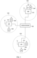
- Figure 1 provides a schematic diagram illustrating the basic functionality of a conventional mobile telecommunications network.
- the network includes a plurality of base stations 101 connected to a core network 102.
- Each base station provides a coverage area 103 (i.e. a cell) within which data can be communicated to and from mobile terminals 104.
- Data is transmitted from a base station 101 to a mobile terminal 104 within a coverage area 103 via a radio downlink.
- Data is transmitted from a mobile terminal 104 to a base station 101 via a radio uplink.
- the core network 102 routes data to and from the mobile terminals 104 and provides functions such as authentication, mobility management, charging and so on.
- the mobile terminals may also be referred to as user equipment (UE) or communications devices and the base stations as enhanced node B (eNodeB) or network elements.
- UE user equipment
- eNodeB enhanced node B
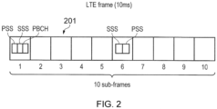
- FIG. 2 shows a schematic diagram illustrating an OFDM based LTE downlink radio frame 201.
- the LTE downlink radio frame is transmitted from an LTE base station (known as an enhanced Node B) and lasts 10 ms.
- the downlink radio frame comprises ten sub-frames, each sub-frame lasting 1 ms.
- a primary synchronisation signal (PSS) and a secondary synchronisation signal (SSS) are transmitted in the first and sixth sub-frames of the LTE frame.
- a primary broadcast channel (PBCH) is transmitted in the first sub-frame of the LTE frame.
- Figure 3 provides a schematic diagram providing a grid which illustrates the structure of an example of a conventional downlink LTE sub-frame.
- the sub-frame comprises a predetermined number of symbols which are transmitted over a 1ms period.
- Each symbol comprises a predetermined number of orthogonal sub-carriers distributed across the bandwidth of the downlink radio carrier.
- the example sub-frame shown in Figure 3 comprises 14 symbols and 1200 sub-carriers spaced across a 20MHz bandwidth.
- the smallest unit on which data can be transmitted in LTE is twelve sub-carriers transmitted over one sub-frame.
- each individual resource element is not shown, instead each individual box in the sub-frame grid corresponds to twelve subcarriers transmitted on one symbol.
- Figure 3 shows resource allocations for four LTE terminals 340, 341, 342, 343.
- the resource allocation 342 for a first LTE terminal extends over five blocks of twelve subcarriers
- the resource allocation 343 for a second LTE terminal extends over six blocks of twelve sub-carriers and so on.
- Control channel data is transmitted in a control region 300 of the sub-frame comprising the first n symbols of the sub-frame where n can vary between one and three symbols for channel bandwidths of 3MHz or greater and where n can vary between two and four symbols for channel bandwidths of 1.4MHz.
- the data transmitted in the control region 300 includes data transmitted on the physical downlink control channel (PDCCH), the physical control format indicator channel (PCFICH) and the physical HARQ indicator channel (PHICH).
- PDCCH physical downlink control channel
- PCFICH physical control format indicator channel
- PHICH physical HARQ indicator channel
- the PDCCH contains control data indicating which sub-carriers on which symbols of the subframe have been allocated to specific communications terminals (UEs).
- UEs communications terminals
- the PDCCH data transmitted in the control region 300 of the sub-frame shown in Figure 3 would indicate that UE1 has been allocated the first block of resources 342, that UE2 has been allocated the second block of resources 343, and so on.
- the PCFICH contains control data indicating the duration of the control region in that sub-frame (i.e. between one and four symbols) and the PHICH contains HARQ (Hybrid Automatic Request) data indicating whether or not previously transmitted uplink data has been successfully received by the network.
- HARQ Hybrid Automatic Request
- symbols in a central band 310 of the sub-frame are used for the transmission of information including the primary synchronisation signal (PSS), the secondary synchronisation signal (SSS) and the physical broadcast channel (PBCH) mentioned above.
- This central band 310 is typically 72 sub-carriers wide (corresponding to a transmission bandwidth of 1.08 MHz).
- the PSS and SSS are synchronisation sequences that once detected allow a communications terminal 104 to achieve frame synchronisation and determine the cell identity of the base station (eNodeB) transmitting the downlink signal.
- the PBCH carries information about the cell, comprising a master information block (MIB) that includes parameters that the communications terminals require to access the cell.
- MIB master information block
- the data transmitted to individual communications terminals on the physical downlink shared channel (PDSCH) can be transmitted in the remaining blocks of communications resource elements of the sub-frame.
- Figure 3 also shows a region of PDSCH 344 containing system information and extending over a bandwidth of R 344 .
- the central frequency carries control channels such as the PSS, SSS and PBCH and therefore implies a minimum bandwidth of a receiver of a communications terminal.
- the number of sub-carriers in an LTE channel can vary depending on the configuration of the transmission network. Typically this variation is from 72 sub carriers contained within a 1.4MHz channel bandwidth to 1200 sub-carriers contained within a 20MHz channel bandwidth as shown in Figure 3 .
- subcarriers carrying data transmitted on the PDCCH, PCFICH and PHICH are typically distributed across the entire bandwidth of the sub-frame. Therefore a conventional communications terminal must be able to receive the entire bandwidth of the sub-frame in order to receive and decode the control region.
- the UEs 104 will be allocated resources in uplink frames by the eNodeB 101. For example, if a UE is in an unconnected state with the eNodeB and wishes to connect to the eNodeB, the UE is required to perform a random access procedure which acts as request for access to the network.
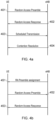
- Figure 4a illustrates an LTE contention based random access procedure that a UE may perform in order to request access to an LTE network.
- the UE selects a random access preamble from a set of contention based random access preambles that has been broadcast in a system information block (SIB) such as SIB2 in a downlink frame by the eNodeB.
- SIB system information block
- the UE transmits the selected random access preamble 401 as a random access message to the eNodeB where this transmission acts as an access request message for requesting access to and resources of the network, and the preamble acts as a UE identifier.
- SIB system information block
- the random access preamble may be transmitted on a physical channel within the wireless access interface such as a physical random access channel (PRACH) of an uplink frame.
- PRACH physical random access channel
- the eNodeB transmits and the UE receives a response message, such as for example, a random access response (RAR) which provides a positive or negative acknowledgment with regards to a resource allocation.
- RAR random access response
- the resources in time and frequency of a physical downlink shared channel(PDSCH) in which the UE can find the RAR are indicated in a control message on a control channel such as physical downlink control channel (PDCCH).
- PDSCH physical downlink shared channel
- the control message is addressed to a random access radio network temporary identifier (RA-RNTI) and is transmitted in the same subframe as the response message. This control message is therefore required to be received prior to receiving the response message.
- RA-RNTI random access radio network temporary identifier
- DCI downlink control information
- the response message contains at least the identity of the received preamble, a timing alignment command, an allocated uplink resource grant and a temporary Cell RNTI (C-RNTI).
- the UE Upon receiving the response message, the UE transmits a scheduled transmission containing its intended message, such as a radio resource controller (RRC) connection request, in the allocated uplink resources as shown by step 403.
- the eNodeB Upon receiving the intended message, the eNodeB transmits a contention resolution message.
- the contention resolution message is then acknowledged by the UE to which the contention resolution message is addressed, for example with a HARQ ACK/NACK. This procedure thus overcomes the possibility of multiple UEs utilising the same preamble and or transmitting a random access request over the same channel at the same time.
- Figure 4b illustrates an example non-contention based random access procedure for requesting resources in an LTE network.
- the eNodeB allocates a preamble from a non-contention based set of preambles to the UE. This allocation may be performed via a format 1A downlink control information (DCI) message on the PDCCH or in a handover command if the UE has recently entered a cell served by the eNodeB.
- DCI downlink control information
- the user device transmits its allocated preamble to the eNodeB.
- the eNodeB transmits a response message, such as for example a random access response (RAR), at step 453 where the response message contains similar information to the response message sent at step 402 of Figure 4a .
- a response message such as for example a random access response (RAR)
- RAR random access response
- the response message is transmitted on a physical downlink shared channel (PDSCH) and is scheduled by information on a physical control channel such as a PDCCH.
- PDSCH physical downlink shared channel
- the response message is transmitted by the eNodeB in a predetermined temporal response message window.
- the access request message is a random access request and the response message is a random access response, such a window may be referred to as a random access response window or a RAR window.
- a response window may reduce the amount of power consumed at the UE because a finite time period during which the UE will attempt to receive a response message is defined.
- the response window is defined with respect to the transmission of the access request message and the UE is configured to begin to attempt to receive the response message when the response window commences.
- the process of receiving a response message includes the UE checking the PDCCH of each subframe within the response window for a relevant DCI containing PDSCH scheduling information addressed to its RA-RNTI. When such scheduling information is found, the UE receives and decodes the response message in the PDSCH of the corresponding subframe, where the response message contains an indication of the preamble the user device sent to the eNodeB in the access request message.
- the UE ceases to check the PDCCH for response message scheduling information. If a response message is not received by a UE within the response window, after a minimum wait period the user device begins a subsequent new access request procedure, where the subsequent access request procedure is similar to those previously described with reference to Figures 4a and 4b .
- Multiple response messages for different UEs may be transmitted by the eNodeB within each response window therefore reducing congestion. If multiple response messages are present in a single response window the user devices may differentiate between them by means of the RA-RNTI to which they are addressed and the preamble they each contain.
- a large number of UEs may contemporaneously transmit a random access message in the form of random access preamble to a same eNodeB.
- MTC machine-type-communication
- Another example is where there may be a larger number of conventional communication devices in one location than are normally served at that location, for example because of a sporting event.
- the eNodeB may be unable to process all the random access requests and or the random access request may interfere with each other. This may lead to the eNodeB unsuccessfully processing some or all the random access messages and therefore the requesting UEs may not receive a random access response message in the form of a resource allocation.
- the default response for a UE when a random access response is not received is to retransmit the random access message and increase the power at which it is transmitted, and continue this repetition until a timer (T300) expires, the timer expiry indicating that a radio resource controller connection has failed to be established.
- a second example where the conventional random access procedure lacks robustness is when the uplink and downlink paths to and from the UE and eNodeB are significantly different and therefore the UE camps on to the incorrect eNodeB.
- This scenario may occur for instance when the downlink signal is received at the UE at an artificially high power.
- a problem such as this has been known to occur in the proximity of a lakes which are situated in between an eNodeB and a UE. In such circumstances, in the downlink the reflection of the signal from the lake causes the received signal at the UE to be received at a high amplitude. Consequently, the UE will select this eNodeB as the network element to communicate with.
- the signal from the UE to eNodeB may be received at a low power or not received at all at the eNodeB. Consequently, if the UE has made a random access request it is possible that the eNodeB will not properly receive it, and hence the UE will not receive a response. This will lead the UE to perform a similar procedure to that described above where it retransmits the random access message and increases the transmission power of the retransmissions. This can in some circumstances cause the UE to fail to obtain any network service, as well as an increase in power consumption at the UE.
- a further problem posed by the above limitations of the current random access procedure is that a UE is unlikely to be able to differentiate between the aforementioned problems because the only indicator available at the UE is an absence of a random access response. Consequently, it would be beneficial if an approach which is able to mitigate both of the above problems can be achieved.
- a proposed solution is for the eNodeB to signal a timer of a fixed duration to the UE or for the UE to use a hard coded timer value to control random access message retransmissions. This timer is triggered when the UE has transmitted a number of random access messages without reply equal to a predetermined threshold. The UE then suspends transmission of further random access messages until the timer has expired. The intention of this delay in transmission is to provide a window to the eNodeB in which it may recover and therefore be in a position to receive and process further random access messages.
- this "back-off' period may for example result in a call establishment for a UE being delayed even when there is not a congestion or load problem at the eNodeB but instead a temporary issue with uplink coverage.
- the use of a fixed period may also lead to large number of UEs retransmitting their random access messages at a similar time, thus resulting in the problem being delayed but not solved.
- using a fixed delay does not take account of the current network conditions which may result in the timers either being too long or too short compared to the congestion in the system. Consequently, it is difficult to configure a timer duration which allows suitable back-off time in cases of high network congestion whilst not causing too much delay to random access request in other cases i.e. low congestion or incorrect cell selection.
- a solution proposed to rectify UEs incorrectly selecting an eNodeB due to artificially high downlink signals is to apply an eNodeB reselection offset so that when a UE detects repeated random access request failures, the UE selects a different eNodeB. For instance, if the eNodeB providing the strongest downlink signal is not responding to repeated random access messages the UE may select an alternative eNodeB from which it receives a downlink signal based on the received signal strength of the new eNodeB being at least a predetermined proportion lower than the previous eNodeB.
- a UE adapts its back-off behaviour and or cell reselection behaviour in order to manage situations where repeated random access messages are not acknowledged and therefore the random access request unsuccessful.
- a UE applies a variable back-off or delay timer when a random access failure condition is detected and increases the back-off time on subsequent random access message transmissions by a fixed or predetermined increment.
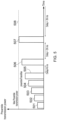
- Figure 5 provides a schematic diagram representing a back-off approach in accordance with the first example embodiment.
- the y-axis represents the power at which a preamble is transmitted as a random access message and the x-axis represents the time at which the preambles are transmitted as a random access message.
- the UE operates in accordance with the LTE standard, for example the UE transmits a first preamble at 501.
- this first transmission does not result in a random access response from the eNodeB and therefore the UE retransmits the preamble at 502 at an increased power. This process continues such that the preamble is retransmitted at 503, 504 and 505 until the preambleTransMax threshold is reached.
- the UE delays a subsequent retransmission by N ms thus next retransmitting the preamble at 506.
- the preamble transmission 506 is shown to be transmitted at an increased power compared to the previous preamble transmission because the maximum transmit power 508 has yet to be reached. However, in some examples the maximum transmission power may have already been reached by preamble transmission 505 and therefore no further increase would be possible. Alternatively, the transmission power may only be increased every other subsequent preamble retransmission for example or according to any chosen pattern. If preamble 506 also does not result in the UE receiving a random access response a subsequent preamble retransmission occurs at 507.
- the retransmission is delayed by 2N ms relative to the previous retransmission in order to give the eNodeB further time to recover from any congestion. If preamble 507 did not result in a random access response form the eNodeB the preamble would be retransmitted after 3Nms and so on. In Figure 5 the delay is calculated in accordance with
- the use of the variable back-off or delay may be dependent on signalling from the eNodeB.
- an additional signalling bit may be introduced into the broadcast system information which specifies whether a UE being served by the eNodeB should implement a variable delay. This information is preferably included in data structures such as the system information so that the UE can receive the signalling prior to establishing an RRC connection with the eNodeB.
- the random access failure condition is defined as transmitting a predetermined number of preambles, the random access failure condition may also correspond to other scenarios. For example, failing to receive an acknowledgment within a predetermined period of time such as the T300 timer found in LTE.
- Figure 6 provides an illustration of a technique in accordance with a second example, where the UE may randomise the delay with which preambles are retransmitted.
- the transmission of the initial preambles 501 to 505 are performed as normal and once a random access failure condition occurs i.e. preambleTransMax is reached, an additional delay is introduced before the next retransmission of the preamble.
- the delay which is introduced is randomised.
- the next preamble retransmission may take place at any time in the range represented by 601 to 608 and the decision is a random choice at the UE in accordance with an appropriate probability distribution, for example a uniform distribution.
- the range may be set according to an appropriate duration, for example the range may be calculated in accordance with any of the formula given below for example.
- the randomised delay there may be a fixed minimum delay onto which a randomly generated delay period is added.
- they could also be dependent upon a UE's identity such as C-RNTI or IMSI.
- randomly determining the delay may be a fairer way to allocate when a UE is to perform a retransmission such that a UE is not consistently allocated one delay or retransmission time.
- random back-off provides a number of advantages over existing techniques. Firstly it reduces the chance that preambles which have previously been transmitted contemporaneously with preambles from other UEs (i.e. 501 to 505) will be retransmitted contemporaneously, thus reduces the likelihood of further congestion. Furthermore, the use of a randomised delay also means that UEs may still retransmit preambles whilst others are in a back-off period thus ensuring that not all preamble retransmissions are suspended.
- a feature of the proposed techniques is that legacy devices will not vary the delay associated with retransmission of preambles and therefore compliant UEs may experience an increased delay compared to legacy UEs. However, the use of a randomised backoff reduces the probability that a compliant UE will experience an increased delay in retransmitting a preamble compared to a legacy device.
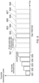
- Figure 7A provides an illustration of a technique in accordance with a third example of the present disclosure.
- a delay being changed for every subsequent preamble retransmission after a random access failure condition has occurred it is varied after a predetermined number of subsequent preamble retransmissions.
- the delays illustrated in Figure 7A are calculated in a manner similar to those of Figure 5 i.e. N, 2 N, 3 N etc. however after each delay a group or set of preamble retransmissions take place.
- Figure 7A it can be seen that after the initial five ( preambleTransMax ) preamble transmissions 501 to 505 and a delay of N ms , a further five preamble retransmissions takes place 701 to 705.
- the UE may commence transmitting another set of preambleTransMax preambles after a 2N ms delay, the set beginning with preamble transmission 706.
- the delay in between sets may be calculated according to any of the formula given above and each set of preamble transmissions may be treated as an independent set such that the transmission power of 701 to 705 for example may correspond to that of preamble transmissions 501 to 505.
- the transmission powers may increase until the maximum preamble transmission power is reached and then this power maintained for subsequent preamble transmissions.
- the approach of the transmission powers increasing until the maximum preamble transmission power is reached and then this power maintained for subsequent preamble transmissions is schematically represented in Figure 7A .
- Reselection of eNodeBs to avoid or rectify incorrect camping-on may be introduced into any of the techniques described.
- cell or eNodeB reselection may take place in between the sets of preamble transmissions. For instance, after preamble transmissions 501 to 505 the UE may remove the current eNodeB from its list of candidate eNodeBs and then direct the transmissions 701 to 705 towards a different eNodeB.
- the current eNodeB may be removed as a result of a default setting that the current eNodeB is removed or may be removed because it signal strength falls above threshold below which the UE is to select a new eNodeB.
- a negative amplitude offset may be applied to the signals received from the current eNodeB (first eNodeB) and then the eNodeB from which the UE receives the best signal (taking into account the offset and other parameters such as hysteresis and priority) is selected (second eNodeB).
- This offset then may be removed once the UE moves away from or reselects from the second eNodeB, or after a predetermined period of time, such that the first eNodeB is not permanently excluded from selection.
- a UE may apply any of the above described examples but then perform eNodeB reselection once the T300 timer or multiple instances of the T300 timer have expired.
- cell access barring may be applied to prevent a terminal device from seeking to reselect the relevant eNodeB.
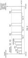
- Figure 8 provides an illustration of a random access procedure where eNodeB reselection is introduced into the technique illustrated in Figure 5 .
- a first random access failure condition occurs, and this triggers the increasing delay between preamble retransmissions as described above.
- the T300 timer expires thus indicating a second different random access failure condition.
- the UE performs eNodeB reselection.
- the network element reselection comprises applying a negative offset to the amplitude of the signals received from the current or first eNodeB and then selecting a second eNodeB to which it will transmit subsequent preambles. This is done by selecting the eNodeB from which it receives what are deemed to be the best signals according to a cell selection or reselection criterion.
- a UE is unlikely to be able to establish why a random access failure has occurred because in general the only indication available is an absence of a random access response, and this does not allow the UE to differentiate between an overloaded cell or where a cell has been incorrectly selected.
- the above described technique of integrated reselection and variable delay retransmission overcomes this problem by providing an approach which can address both these failure scenarios. For example, when preambleTransMax preambles have been transmitted, action to address an overloaded cell is performed whereas when the T300 timer runs out action to address incorrect cell selection is performed.
- preamble retransmission techniques and eNodeB reselection techniques require a number of parameters to be provided to the UEs. These parameters may either be hardcoded into UEs or may for example be signalled to UE in the broadcast system information messages transmitted by the eNodeB. In the case where the parameters are provided in the system information they may be provided in a new information element. Such an information element may include one or more of preambleTransMaxDelay, reselectionOffset, preambleTransMax and preambleTransMaxDelayOffset. In one example of preambleTransMaxDelay and reselectionOffset may be broadcast together so that signalling overheads in a system are reduced.
- UEs may be provided with default values for the above mentioned parameters, these default parameters may be used until the network broadcasts new values which are intended to override the default values.
- the technique proposed in this disclosure may only be applied by a UE if a serving eNodeB indicates to a UE that they should be applied. This approach can once again be achieved by introducing further signalling into a broadcast message.
- Figure 9 provides a diagram of the messages exchanged between a UE and eNodeB operating in accordance with the technique described with reference to Figure 5 .
- the UE first acquires a preamble at 901.
- the UE then repeatedly transmits the preamble to the eNodeB because a random access response is not received in reply to any of the preamble transmissions 902 to 906.
- the next preamble transmission 908 is therefore delayed by 2 N ms.
- Preamble transmission 908 is then successfully received by the eNodeB and a random access response 909 is received by the UE, thus completing the random access procedure.
- Figure 9 illustrates a delay which increases as an arithmetic progression the delay may be calculated in accordance with any of the examples described above and multiple preamble transmission may occur between delays as illustrated in Figures 7A and 7B .
- eNodeB reselection may occur during delay period as previously described.
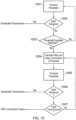
- FIG 10 provides a flow diagram which provides an alternative illustration of the operation at the UE of the technique illustrated in Figure 5 and 6 .
- a preamble is initially transmitted at 1001 and if a random access response (RAR) is received from the eNodeB in response 1002, a scheduled transmission occurs and the random access procedure is complete. If a RAR is not received and the number of preamble transmission has not reached preambleTransMax 1003 then the UE performs a further transmission of the preamble 1001. However, if preambleTransMax has been reached 1003 the UE calculates the delay which should be implemented 1004 before the next transmission of the preamble 1005.
- RAR random access response
- Steps of cell reselection, transmission power increase or preamble transmission groupings may also be added to Figure 10 such that any of the techniques proposed by the present disclosure can be combined. For instance, cell reselection may occur prior to delay calculation if the outcome of step 1003 is "yes".
- FIG 11 provides a schematic diagram of a UE 1101 and an eNodeB 1105 in which the techniques described above may be implemented.
- the UE includes a transmitter 1102 for transmitting data to the eNodeB 1105 and a receiver 1103 for receiving data from the eNodeB 1105.
- the transmitter 1102 and the receiver 1103 may allow the UE to transmit a preamble to the eNodeB and receive a random access response from the eNodeB 1105.
- the controller 1104 may also calculate the timing of when to transmit the preamble and select the eNodeB to which the preamble(s) should be transmitted.
- the eNodeB 1105 includes a transmitter 1006 for transmitting data to the UE 1101 and a receiver 1007 for receiving data from the UE 1101, under the control of a controller 1108.
- the controller 1108 may control process received preambles and control the transmitter to transmit random access responses.
- the controller may also control the transmitter to transmit signalling which indicates to the UE whether variable delay preamble transmission should be implemented and the relevant parameters of the variable delay preamble transmission.
- the eNodeB 1105 has been illustrated as including a transmitter and a receiver, the eNodeB is not limited to including these elements and may also include further elements such as memory for example.
- Embodiments of the present invention have been defined largely in terms of reduced capability terminals transmitting data via a virtual carrier inserted in a conventional LTE based host carrier. However, it will be understood that any suitable device can transmit and receive data using the described virtual carriers for example devices which have the same capability as a conventional LTE type terminal or devices which have enhanced capabilities.
Landscapes
- Engineering & Computer Science (AREA)
- Computer Networks & Wireless Communication (AREA)
- Signal Processing (AREA)
- Mobile Radio Communication Systems (AREA)
Claims (11)
- Dispositif de communication (104) pour communiquer par l'intermédiaire d'un réseau de communication mobile, le réseau de communication mobile comprenant un ou plusieurs éléments de réseau (101) fournissant une interface d'accès sans fil pour transmettre des signaux vers, ou recevoir des signaux depuis, le dispositif de communication, le dispositif de communication comprenant :un émetteur configuré pour transmettre les signaux au réseau de communication mobile par l'intermédiaire de l'interface d'accès sans fil fournie par les un ou plusieurs éléments de réseau du réseau de communication mobile, etun récepteur configuré pour recevoir les signaux du réseau de communication mobile par l'intermédiaire de l'interface d'accès sans fil fournie par les un ou plusieurs éléments de réseau du réseau de communication mobile, etun contrôleur configuré pour contrôler l'émetteur pour transmettre un message d'accès aléatoire (501) à un premier élément de réseau par l'intermédiaire d'un canal d'accès aléatoire de l'interface d'accès sans fil qui est commun à un ou plusieurs autres dispositifs de communication,pour recevoir du premier élément de réseau un accusé de réception en réponse au message d'accès aléatoire fournissant une indication d'une allocation de ressources de communication d'un canal de liaison montante partagé pour que le dispositif de communication transmette des signaux au premier élément de réseau, ou un accusé de réception négatif fournissant une indication que le dispositif de communication ne s'est pas vu attribuer des ressources de communication du canal de liaison montante partagé, où :
en réponse à la détection par le contrôleur d'une première condition d'échec de l'accès aléatoire, le contrôleur est configuré en combinaison avec l'émetteur : pour retransmettre le message d'accès aléatoire une ou plusieurs fois (506, 507), chaque retransmission du message d'accès aléatoire étant effectuée après un délai variable supérieur ou égal au délai d'une retransmission précédente, et chaque retransmission du message d'accès aléatoire étant transmise avec une puissance accrue par rapport à celle d'une retransmission précédente, eten réponse à la détection par le contrôleur d'une deuxième condition d'échec de l'accès aléatoire différente de la première condition d'échec de l'accès aléatoire, le contrôleur est configuré, en combinaison avec l'émetteur :
pour sélectionner un second élément de réseau auquel transmettre un message d'accès aléatoire subséquent, le second élément de réseau ayant été sélectionné conformément à un critère de sélection ou de resélection d'élément de réseau. - Dispositif de communication tel que revendiqué dans la revendication 1, dans lequel chaque délai avant la retransmission du message d'accès aléatoire est constitué d'un délai choisi au hasard entre une période de délai minimum et une période de délai maximum, où la période de délai maximum associée à chaque retransmission est supérieure à celle d'une retransmission précédente.
- Dispositif de communication tel que revendiqué dans la revendication 1, dans lequel le critère de sélection ou de resélection de l'élément de réseau comprend un décalage négatif configuré pour être appliqué à une intensité de signal des signaux reçus du premier élément de réseau, et le contrôleur est configuré en combinaison avec le récepteur et l'émetteur :pour recevoir les signaux transmis par les un ou plusieurs éléments de réseau,pour déterminer l'intensité de signal de chacun des signaux reçus de chacun des un ou plusieurs éléments de réseau, et établir des paramètres correspondants associés au critère de sélection ou de resélection,pour appliquer le décalage négatif au paramètre associé au critère de sélection ou de resélection associé au premier élément de réseau, etpour sélectionner le second élément de réseau selon le critère de sélection ou de resélection associé aux éléments de réseau respectifs.
- Dispositif de communication tel que revendiqué dans la revendication 3, dans lequel le décalage a une taille qui a pour effet d'empêcher la resélection du premier élément de réseau.
- Dispositif de communication tel que revendiqué dans la revendication 1, dans lequel les conditions d'échec de l'accès aléatoire comprennent la transmission du message d'accès aléatoire un nombre prédéterminé de fois.
- Dispositif de communication tel que revendiqué dans la revendication 1, dans lequel les conditions d'échec de l'accès aléatoire comprennent l'absence de réception, dans un délai prédéterminé, d'un accusé de réception fournissant une indication d'une allocation du canal partagé de liaison montante.
- Dispositif de communication tel que revendiqué dans la revendication 1, dans lequel le contrôleur est configuré, en combinaison avec le récepteur, pour recevoir un message de diffusion du premier élément de réseau, le message de diffusion indiquant une ou plusieurs des conditions d'échec de l'accès aléatoire.
- Dispositif de communication tel que revendiqué dans la revendication 1, dans lequel le message d'accès aléatoire est retransmis à une puissance inférieure ou égale à une puissance d'émission maximale.
- Dispositif de communication tel que revendiqué dans la revendication 1, dans lequel le contrôleur est configuré en combinaison avec le récepteur pour recevoir un message de diffusion du premier élément de réseau, le délai étant calculé en fonction d'un paramètre indiqué dans le message de diffusion.
- Dispositif de communication tel que revendiqué dans la revendication 1, dans lequel le contrôleur est configuré en combinaison avec le récepteur pour recevoir un message de diffusion du premier élément de réseau, un paramètre de critère de resélection de l'élément de réseau étant indiqué dans le message de diffusion.
- Circuit pour un dispositif de communication (104) destiné à communiquer par l'intermédiaire d'un réseau de communication mobile, le réseau de communication mobile comprenant un ou plusieurs éléments de réseau (101) fournissant une interface d'accès sans fil pour transmettre des signaux vers, ou recevoir des signaux depuis, le dispositif de communication, le dispositif de communication comprenant :un circuit émetteur configuré pour transmettre les signaux au réseau de communication mobile par l'intermédiaire de l'interface d'accès sans fil fournie par les un ou plusieurs éléments de réseau du réseau de communication mobile, etun circuit récepteur configuré pour recevoir les signaux du réseau de communication mobile par l'intermédiaire de l'interface d'accès sans fil fournie par les un ou plusieurs éléments de réseau du réseau de communication mobile, etun circuit contrôleur configuré pour contrôler le circuit émetteur :pour transmettre un message d'accès aléatoire (501) à un premier élément de réseau par l'intermédiaire d'un canal d'accès aléatoire de l'interface d'accès sans fil qui est commun à un ou plusieurs autres dispositifs de communication,pour recevoir du premier élément de réseau un accusé de réception en réponse au message d'accès aléatoire fournissant une indication d'une allocation de ressources de communication d'un canal de liaison montante partagé pour que le dispositif de communication transmette des signaux au premier élément de réseau, ou un accusé de réception négatif fournissant une indication que le dispositif de communication ne s'est pas vu attribuer des ressources de communication du canal de liaison montante partagé, où :en réponse à la détection par le circuit contrôleur d'une première condition d'échec de l'accès aléatoire, le circuit contrôleur est configuré en combinaison avec le circuit émetteur :
pour retransmettre le message d'accès aléatoire une ou plusieurs fois (506, 507), chaque retransmission du message d'accès aléatoire étant effectuée après un délai variable supérieur ou égal au délai d'une retransmission précédente, et chaque retransmission du message d'accès aléatoire étant transmise avec une puissance accrue par rapport à celle d'une retransmission précédente, eten réponse à la détection par le contrôleur d'une deuxième condition d'échec de l'accès aléatoire différente de la première condition d'échec de l'accès aléatoire, le contrôleur est configuré, en combinaison avec l'émetteur :
pour sélectionner un second élément de réseau auquel transmettre un message d'accès aléatoire subséquent, le second élément de réseau ayant été sélectionné conformément à un critère de sélection ou de resélection d'élément de réseau.
Applications Claiming Priority (3)
| Application Number | Priority Date | Filing Date | Title |
|---|---|---|---|
| EP13185460 | 2013-09-20 | ||
| EP14766925.3A EP3039938B1 (fr) | 2013-09-20 | 2014-09-03 | Dispositif et procédé de communications pour l'amélioration de la transmission de messages d'accès aléatoire |
| PCT/EP2014/068733 WO2015039870A1 (fr) | 2013-09-20 | 2014-09-03 | Dispositif et procédé de communications pour l'amélioration de la transmission de messages d'accès aléatoire |
Related Parent Applications (2)
| Application Number | Title | Priority Date | Filing Date |
|---|---|---|---|
| EP14766925.3A Division EP3039938B1 (fr) | 2013-09-20 | 2014-09-03 | Dispositif et procédé de communications pour l'amélioration de la transmission de messages d'accès aléatoire |
| EP14766925.3A Division-Into EP3039938B1 (fr) | 2013-09-20 | 2014-09-03 | Dispositif et procédé de communications pour l'amélioration de la transmission de messages d'accès aléatoire |
Publications (2)
| Publication Number | Publication Date |
|---|---|
| EP3531789A1 EP3531789A1 (fr) | 2019-08-28 |
| EP3531789B1 true EP3531789B1 (fr) | 2023-07-12 |
Family
ID=49230598
Family Applications (2)
| Application Number | Title | Priority Date | Filing Date |
|---|---|---|---|
| EP19161706.7A Active EP3531789B1 (fr) | 2013-09-20 | 2014-09-03 | Dispositif de communications pour l'amélioration de la transmission de messages d'accès aléatoire |
| EP14766925.3A Active EP3039938B1 (fr) | 2013-09-20 | 2014-09-03 | Dispositif et procédé de communications pour l'amélioration de la transmission de messages d'accès aléatoire |
Family Applications After (1)
| Application Number | Title | Priority Date | Filing Date |
|---|---|---|---|
| EP14766925.3A Active EP3039938B1 (fr) | 2013-09-20 | 2014-09-03 | Dispositif et procédé de communications pour l'amélioration de la transmission de messages d'accès aléatoire |
Country Status (11)
| Country | Link |
|---|---|
| US (3) | US9832794B2 (fr) |
| EP (2) | EP3531789B1 (fr) |
| JP (1) | JP6740130B2 (fr) |
| KR (2) | KR102027634B1 (fr) |
| CN (2) | CN111478760A (fr) |
| AU (1) | AU2014323351A1 (fr) |
| BR (1) | BR112016005431B1 (fr) |
| CA (1) | CA2923551A1 (fr) |
| RU (1) | RU2683554C2 (fr) |
| TW (1) | TWI628930B (fr) |
| WO (1) | WO2015039870A1 (fr) |
Families Citing this family (42)
| Publication number | Priority date | Publication date | Assignee | Title |
|---|---|---|---|---|
| TWI628930B (zh) * | 2013-09-20 | 2018-07-01 | 新力股份有限公司 | 通訊裝置及方法 |
| JP6422999B2 (ja) * | 2014-06-13 | 2018-11-14 | アップル インコーポレイテッドApple Inc. | 省電力化、範囲の改善、及び改善された検出のための拡張されたprachスキーム |
| US11343680B2 (en) * | 2014-09-29 | 2022-05-24 | Qualcomm Incorporated | Techniques for accessing a cell using an unlicensed radio frequency spectrum band |
| WO2016114691A1 (fr) * | 2015-01-13 | 2016-07-21 | Telefonaktiebolaget Lm Ericsson (Publ) | Nœud de réseau, dispositif sans fil et procédé associé réalisé par ceux-ci pour utilisation dans une procédure d'accès aléatoire entre ceux-ci dans une cellule du nœud de réseau |
| WO2016121910A1 (fr) * | 2015-01-29 | 2016-08-04 | 株式会社Nttドコモ | Terminal d'utilisateur, station de base radio et procédé de radiocommunication |
| US10178583B2 (en) * | 2015-07-15 | 2019-01-08 | Lg Electronics Inc. | Method for transmitting or receiving information on network access of terminal in wireless communication system and apparatus therefor |
| CN107925994B (zh) * | 2015-08-07 | 2022-04-08 | 瑞典爱立信有限公司 | 用于资源请求的方法和装置 |
| US10652923B2 (en) * | 2015-09-25 | 2020-05-12 | Sony Corporation | Method for indicating the allocated resources for a HARQ message in a random access procedure for a low-complexity, narrowband terminal |
| CN106658613B (zh) * | 2015-11-03 | 2020-04-14 | 中国移动通信集团公司 | 一种小区重选方法及装置 |
| US20170135115A1 (en) * | 2015-11-10 | 2017-05-11 | Lg Electronics Inc. | Method and apparatus for transmitting and receiving data for mobile terminal in wireless communication system |
| CN107105504B (zh) * | 2016-02-19 | 2021-10-15 | 中兴通讯股份有限公司 | 一种系统接入的资源分配方法和装置 |
| US20170265230A1 (en) * | 2016-03-14 | 2017-09-14 | Futurewei Technologies, Inc. | System and Method for Random Access Backoffs |
| CN107277933B (zh) * | 2016-04-06 | 2023-05-02 | 中兴通讯股份有限公司 | 随机接入信道拥塞处理方法及装置 |
| JP6962337B2 (ja) * | 2016-05-11 | 2021-11-05 | ソニーグループ株式会社 | ワイヤレスシステムにおける分散型制御 |
| WO2017220247A1 (fr) * | 2016-06-22 | 2017-12-28 | Sony Corporation | Dispositifs et procédés de communication |
| US11546802B2 (en) * | 2016-08-10 | 2023-01-03 | Samsung Electronics Co., Ltd. | Method and apparatus for supporting flexible UE bandwidth in next generation communication system |
| CN107734714B (zh) | 2016-08-12 | 2023-04-18 | 中兴通讯股份有限公司 | 无线通信系统中的随机接入方法和装置、用户终端 |
| WO2018062771A1 (fr) * | 2016-09-29 | 2018-04-05 | Samsung Electronics Co., Ltd. | Procédé et appareil de prise en charge de services multiples dans un système de communication sans fil |
| KR102146696B1 (ko) * | 2016-10-07 | 2020-08-21 | 에스케이 텔레콤주식회사 | 단말기 무선자원의 스케줄링을 위한 방법 및 장치 |
| EP4054271A1 (fr) | 2016-10-07 | 2022-09-07 | Samsung Electronics Co., Ltd. | Procédé et appareil permettant d'exécuter une procédure d'accès aléatoire basée sur la contention |
| EP3554175B1 (fr) * | 2016-12-16 | 2021-02-03 | Guangdong Oppo Mobile Telecommunications Corp., Ltd. | Procédés et appareil d'accès aléatoire |
| SG11201906123VA (en) * | 2017-01-05 | 2019-08-27 | Guangdong Oppo Mobile Telecommunications Corp Ltd | Method for random access and terminal device |
| CN108289014A (zh) * | 2017-01-08 | 2018-07-17 | 株式会社Ntt都科摩 | 在上行混合自动重传(harq)中使用的传输方法、基站及移动台 |
| EP4027728A1 (fr) | 2017-01-11 | 2022-07-13 | MediaTek Inc. | Fonctionnement efficace en large bande passante et adaptation efficace de la bande passante rf spécifique à l'ue |
| US20180279384A1 (en) * | 2017-03-24 | 2018-09-27 | Mediatek Inc. | Two-Phase Backoff for Access Procedure in Wireless Communication Systems |
| KR102362403B1 (ko) | 2017-06-05 | 2022-02-14 | 삼성전자 주식회사 | 차세대 이동통신 시스템에서 프리엠블을 이용하여 시스템 정보를 요청하는 방법 및 장치 |
| KR102369471B1 (ko) * | 2017-08-07 | 2022-03-03 | 삼성전자 주식회사 | 무선 통신 시스템에서 추가적인 상향링크 주파수를 지원하기 위한 방법 및 장치 |
| US11259332B2 (en) | 2017-09-19 | 2022-02-22 | Beijing Xiaomi Mobile Software Co., Ltd. | Random access method and apparatus, and electronic device and computer-readable storage medium |
| TW201927027A (zh) * | 2017-11-23 | 2019-07-01 | 財團法人資訊工業策進會 | 行動裝置及其網路資源隨機存取方法 |
| GB2572336B (en) * | 2018-03-26 | 2022-02-02 | Samsung Electronics Co Ltd | Improvements in and relating to random access in a telecommunication network |
| FR3080254A1 (fr) | 2018-04-13 | 2019-10-18 | Orange | Dispositifs, systemes et procedes de communication sans fil pour l'etablissement de services critique en latence |
| CN110557271B (zh) * | 2018-05-31 | 2021-08-24 | 维沃移动通信有限公司 | 一种信息交互方法及终端 |
| WO2019241961A1 (fr) * | 2018-06-21 | 2019-12-26 | 华为技术有限公司 | Procédé de communication, station de base et terminal |
| EP3797556A1 (fr) * | 2018-08-08 | 2021-03-31 | Huawei Technologies Co., Ltd. | Dispositifs, procédés et programmes informatiques pour économiser des ressources de fréquence dans les communications sans fil |
| WO2020107429A1 (fr) * | 2018-11-30 | 2020-06-04 | Oppo广东移动通信有限公司 | Procédé et dispositif d'accès aléatoire |
| WO2020154992A1 (fr) * | 2019-01-30 | 2020-08-06 | Qualcomm Incorporated | Procédure d'accès aléatoire basée sur une procédure de canal d'accès aléatoire en deux étapes et sur une procédure de canal d'accès aléatoire en quatre étapes |
| WO2020164825A1 (fr) * | 2019-02-15 | 2020-08-20 | Sony Corporation | Dispositif de communication, équipement d'infrastructure et procédés |
| EP4016888A4 (fr) * | 2019-08-13 | 2022-08-24 | Beijing Xiaomi Mobile Software Co., Ltd. | Procédé et appareil de rétroaction harq et support de stockage lisible |
| US11252765B2 (en) * | 2019-08-15 | 2022-02-15 | Ofinno, Llc | Reception of split random access response |
| CN112153682B (zh) * | 2020-09-24 | 2023-03-24 | 重庆智慧水务有限公司 | 一种无线局域网的网络自动优化方法 |
| US11452035B2 (en) * | 2021-06-14 | 2022-09-20 | Ultralogic 6G, Llc | Hailing procedure for V2R, V2V, and V2X initial contact in 5G and 6G |
| US11337257B1 (en) * | 2021-12-23 | 2022-05-17 | King Abdulaziz University | Random-access channel in 5G networks |
Family Cites Families (27)
| Publication number | Priority date | Publication date | Assignee | Title |
|---|---|---|---|---|
| US6075779A (en) * | 1997-06-09 | 2000-06-13 | Lucent Technologies, Inc. | Random access channel congestion control for broadcast teleservice acknowledgment messages |
| EP1511346B1 (fr) | 1999-03-10 | 2017-11-22 | Thomson Licensing SAS | Procédé et appareil de transmission d'un salve d'accès aléatoire |
| EP1198076A1 (fr) | 2000-10-10 | 2002-04-17 | Siemens Aktiengesellschaft | Procédé et appareil pour initiation de communication |
| US20070064665A1 (en) * | 2005-08-23 | 2007-03-22 | Interdigital Technology Corporation | Method and apparatus for accessing an uplink random access channel in a single carrier frequency division multiple access system |
| US9125092B2 (en) * | 2005-12-22 | 2015-09-01 | Qualcomm Incorporated | Methods and apparatus for reporting and/or using control information |
| RU2388153C1 (ru) | 2006-08-23 | 2010-04-27 | ЭлДжи ЭЛЕКТРОНИКС ИНК. | Способ запроса радиоресурсов для пакетной передачи восходящей линии в системе gprs |
| EP2090042B1 (fr) | 2006-10-30 | 2012-04-11 | Nokia Corporation | Fourniture de paramètres pour l'accès aléatoire sur un canal dédié amélioré (e-dch) |
| EP3627951A1 (fr) * | 2007-08-08 | 2020-03-25 | Huawei Technologies Co., Ltd. | Système de communication radio et dispositif de station mobile |
| ATE510434T1 (de) | 2007-11-01 | 2011-06-15 | Koninkl Philips Electronics Nv | Verbesserte leistungserhöhung für rach |
| EP2086276B1 (fr) * | 2008-01-31 | 2016-11-02 | LG Electronics Inc. | Procédé de signalisation d'informations pour la reprise de transmission en accès aléatoire |
| US8682318B2 (en) * | 2008-02-04 | 2014-03-25 | Lg Electronics Inc. | Method of performing random access after applying back-off |
| ES2784542T3 (es) * | 2008-03-19 | 2020-09-28 | Nec Corp | Sistema de comunicación, estación de telefonía móvil, estación base, método de decisión de respuesta, método de decisión de configuración de los recursos y programa |
| CN101572921B (zh) | 2008-04-29 | 2013-07-31 | 株式会社Ntt都科摩 | 移动通信系统中的小区重选方法及装置 |
| KR101122095B1 (ko) * | 2009-01-05 | 2012-03-19 | 엘지전자 주식회사 | 불필요한 재전송 방지를 위한 임의접속 기법 및 이를 위한 단말 |
| WO2010124440A1 (fr) * | 2009-04-27 | 2010-11-04 | 华为技术有限公司 | Procédé, dispositif et système de résolution de conflits d'accès aléatoire |
| TWI444076B (zh) * | 2009-07-14 | 2014-07-01 | Htc Corp | 處理隨機存取程序的方法及其相關通訊裝置 |
| JP5454123B2 (ja) | 2009-12-16 | 2014-03-26 | ソニー株式会社 | ハンドオーバのための方法、端末装置及び無線通信システム |
| JP5521907B2 (ja) * | 2010-08-30 | 2014-06-18 | 富士通株式会社 | 基地局および制御方法 |
| ES2528131T3 (es) * | 2010-10-01 | 2015-02-04 | Telefonaktiebolaget L M Ericsson (Publ) | Terminal móvil, estación base y métodos dentro de la misma |
| US8462721B2 (en) * | 2010-10-04 | 2013-06-11 | Intel Mobile Communications GmbH | Radio base stations, mobile radio terminals, methods for controlling a radio base station, and methods for controlling a mobile radio terminal |
| RU2464747C1 (ru) | 2011-04-04 | 2012-10-20 | Александр Иннокентьевич Лаженицын | Плазмотрон физиотерапевтический |
| KR101781864B1 (ko) * | 2011-04-13 | 2017-09-26 | 엘지전자 주식회사 | 무선 접속 시스템에서 랜덤 억세스 성공률을 높이기 위한 셀 재선택 방법 |
| JP2013017060A (ja) * | 2011-07-05 | 2013-01-24 | Sharp Corp | 無線通信システム、基地局装置、移動局装置、無線通信方法及び集積回路 |
| US8718667B2 (en) * | 2011-08-05 | 2014-05-06 | Apple, Inc. | Adaptive random access channel retransmission |
| SG2014010318A (en) * | 2011-08-11 | 2014-05-29 | Interdigital Patent Holdings | Fallback to r99 prach |
| US8688166B2 (en) * | 2011-10-17 | 2014-04-01 | Intel Corporation | Call establishment in highly congested network environment |
| TWI628930B (zh) * | 2013-09-20 | 2018-07-01 | 新力股份有限公司 | 通訊裝置及方法 |
-
2014
- 2014-08-06 TW TW103126906A patent/TWI628930B/zh active
- 2014-09-03 JP JP2016543354A patent/JP6740130B2/ja active Active
- 2014-09-03 CN CN202010264083.0A patent/CN111478760A/zh active Pending
- 2014-09-03 CN CN201480051707.3A patent/CN105557056B/zh active Active
- 2014-09-03 WO PCT/EP2014/068733 patent/WO2015039870A1/fr active Application Filing
- 2014-09-03 KR KR1020167006884A patent/KR102027634B1/ko active IP Right Grant
- 2014-09-03 EP EP19161706.7A patent/EP3531789B1/fr active Active
- 2014-09-03 BR BR112016005431-8A patent/BR112016005431B1/pt not_active IP Right Cessation
- 2014-09-03 US US14/914,445 patent/US9832794B2/en active Active
- 2014-09-03 AU AU2014323351A patent/AU2014323351A1/en not_active Abandoned
- 2014-09-03 KR KR1020197018846A patent/KR102181920B1/ko active IP Right Grant
- 2014-09-03 RU RU2016115107A patent/RU2683554C2/ru active
- 2014-09-03 EP EP14766925.3A patent/EP3039938B1/fr active Active
- 2014-09-03 CA CA2923551A patent/CA2923551A1/fr active Pending
-
2017
- 2017-10-18 US US15/787,392 patent/US10111256B2/en active Active
-
2018
- 2018-10-11 US US16/157,728 patent/US10575337B2/en active Active
Also Published As
| Publication number | Publication date |
|---|---|
| US20190045555A1 (en) | 2019-02-07 |
| KR20190080977A (ko) | 2019-07-08 |
| EP3039938B1 (fr) | 2019-05-08 |
| CN111478760A (zh) | 2020-07-31 |
| US20180042053A1 (en) | 2018-02-08 |
| KR20160058104A (ko) | 2016-05-24 |
| TW201513596A (zh) | 2015-04-01 |
| EP3039938A1 (fr) | 2016-07-06 |
| JP6740130B2 (ja) | 2020-08-12 |
| BR112016005431A2 (fr) | 2017-08-01 |
| EP3531789A1 (fr) | 2019-08-28 |
| RU2016115107A3 (fr) | 2018-07-02 |
| US10575337B2 (en) | 2020-02-25 |
| CN105557056B (zh) | 2020-05-01 |
| WO2015039870A9 (fr) | 2015-10-08 |
| BR112016005431B1 (pt) | 2023-03-21 |
| CN105557056A (zh) | 2016-05-04 |
| JP2016534676A (ja) | 2016-11-04 |
| AU2014323351A1 (en) | 2016-03-10 |
| KR102027634B1 (ko) | 2019-10-01 |
| US9832794B2 (en) | 2017-11-28 |
| RU2683554C2 (ru) | 2019-03-29 |
| TWI628930B (zh) | 2018-07-01 |
| US10111256B2 (en) | 2018-10-23 |
| KR102181920B1 (ko) | 2020-11-23 |
| WO2015039870A1 (fr) | 2015-03-26 |
| RU2016115107A (ru) | 2017-10-25 |
| US20160219626A1 (en) | 2016-07-28 |
| CA2923551A1 (fr) | 2015-03-26 |
Similar Documents
| Publication | Publication Date | Title |
|---|---|---|
| US10575337B2 (en) | Communications device and method for improving the transmission of random access messages | |
| US11929833B2 (en) | HARQ feedback for unscheduled uplink | |
| US10813137B2 (en) | Method and apparatus of handling BWP inactivity timer during random access procedure in a wireless communication system | |
| US11006441B2 (en) | Method and apparatus of preventing bandwidth part misalignment in a wireless communication system | |
| CN110741717A (zh) | 新无线中的差异化随机接入 | |
| US11206686B2 (en) | Listen before talk for uplink transmission | |
| EP3493608A1 (fr) | Dispositif terminal, dispositif station de base et procédé de communication | |
| EP3493639A1 (fr) | Dispositif terminal, dispositif station de base et procédé de communication | |
| WO2019029695A1 (fr) | Procédé et appareil de régulation de puissance | |
| EP3751943A1 (fr) | Procédé et appareil d'émission d'un préambule d'accès aléatoire dans une bande sans licence | |
| CN111132360B (zh) | 消息发送、消息配置方法及装置、存储介质 |
Legal Events
| Date | Code | Title | Description |
|---|---|---|---|
| PUAI | Public reference made under article 153(3) epc to a published international application that has entered the european phase |
Free format text: ORIGINAL CODE: 0009012 |
|
| STAA | Information on the status of an ep patent application or granted ep patent |
Free format text: STATUS: REQUEST FOR EXAMINATION WAS MADE |
|
| 17P | Request for examination filed |
Effective date: 20190408 |
|
| AC | Divisional application: reference to earlier application |
Ref document number: 3039938 Country of ref document: EP Kind code of ref document: P |
|
| AK | Designated contracting states |
Kind code of ref document: A1 Designated state(s): AL AT BE BG CH CY CZ DE DK EE ES FI FR GB GR HR HU IE IS IT LI LT LU LV MC MK MT NL NO PL PT RO RS SE SI SK SM TR |
|
| STAA | Information on the status of an ep patent application or granted ep patent |
Free format text: STATUS: EXAMINATION IS IN PROGRESS |
|
| 17Q | First examination report despatched |
Effective date: 20200702 |
|
| STAA | Information on the status of an ep patent application or granted ep patent |
Free format text: STATUS: EXAMINATION IS IN PROGRESS |
|
| RAP3 | Party data changed (applicant data changed or rights of an application transferred) |
Owner name: SONY GROUP CORPORATION |
|
| GRAP | Despatch of communication of intention to grant a patent |
Free format text: ORIGINAL CODE: EPIDOSNIGR1 |
|
| STAA | Information on the status of an ep patent application or granted ep patent |
Free format text: STATUS: GRANT OF PATENT IS INTENDED |
|
| RIC1 | Information provided on ipc code assigned before grant |
Ipc: H04W 56/00 20090101ALN20230119BHEP Ipc: H04W 28/02 20090101ALI20230119BHEP Ipc: H04W 74/08 20090101AFI20230119BHEP |
|
| INTG | Intention to grant announced |
Effective date: 20230206 |
|
| GRAS | Grant fee paid |
Free format text: ORIGINAL CODE: EPIDOSNIGR3 |
|
| GRAA | (expected) grant |
Free format text: ORIGINAL CODE: 0009210 |
|
| STAA | Information on the status of an ep patent application or granted ep patent |
Free format text: STATUS: THE PATENT HAS BEEN GRANTED |
|
| AC | Divisional application: reference to earlier application |
Ref document number: 3039938 Country of ref document: EP Kind code of ref document: P |
|
| AK | Designated contracting states |
Kind code of ref document: B1 Designated state(s): AL AT BE BG CH CY CZ DE DK EE ES FI FR GB GR HR HU IE IS IT LI LT LU LV MC MK MT NL NO PL PT RO RS SE SI SK SM TR |
|
| REG | Reference to a national code |
Ref country code: CH Ref legal event code: EP |
|
| REG | Reference to a national code |
Ref country code: DE Ref legal event code: R096 Ref document number: 602014087646 Country of ref document: DE |
|
| REG | Reference to a national code |
Ref country code: IE Ref legal event code: FG4D |
|
| REG | Reference to a national code |
Ref country code: NL Ref legal event code: FP |
|
| REG | Reference to a national code |
Ref country code: LT Ref legal event code: MG9D |
|
| REG | Reference to a national code |
Ref country code: AT Ref legal event code: MK05 Ref document number: 1588422 Country of ref document: AT Kind code of ref document: T Effective date: 20230712 |
|
| PG25 | Lapsed in a contracting state [announced via postgrant information from national office to epo] |
Ref country code: GR Free format text: LAPSE BECAUSE OF FAILURE TO SUBMIT A TRANSLATION OF THE DESCRIPTION OR TO PAY THE FEE WITHIN THE PRESCRIBED TIME-LIMIT Effective date: 20231013 |
|
| PG25 | Lapsed in a contracting state [announced via postgrant information from national office to epo] |
Ref country code: ES Free format text: LAPSE BECAUSE OF FAILURE TO SUBMIT A TRANSLATION OF THE DESCRIPTION OR TO PAY THE FEE WITHIN THE PRESCRIBED TIME-LIMIT Effective date: 20230712 |
|
| PG25 | Lapsed in a contracting state [announced via postgrant information from national office to epo] |
Ref country code: IS Free format text: LAPSE BECAUSE OF FAILURE TO SUBMIT A TRANSLATION OF THE DESCRIPTION OR TO PAY THE FEE WITHIN THE PRESCRIBED TIME-LIMIT Effective date: 20231112 |
|
| PG25 | Lapsed in a contracting state [announced via postgrant information from national office to epo] |
Ref country code: SE Free format text: LAPSE BECAUSE OF FAILURE TO SUBMIT A TRANSLATION OF THE DESCRIPTION OR TO PAY THE FEE WITHIN THE PRESCRIBED TIME-LIMIT Effective date: 20230712 Ref country code: RS Free format text: LAPSE BECAUSE OF FAILURE TO SUBMIT A TRANSLATION OF THE DESCRIPTION OR TO PAY THE FEE WITHIN THE PRESCRIBED TIME-LIMIT Effective date: 20230712 Ref country code: PT Free format text: LAPSE BECAUSE OF FAILURE TO SUBMIT A TRANSLATION OF THE DESCRIPTION OR TO PAY THE FEE WITHIN THE PRESCRIBED TIME-LIMIT Effective date: 20231113 Ref country code: NO Free format text: LAPSE BECAUSE OF FAILURE TO SUBMIT A TRANSLATION OF THE DESCRIPTION OR TO PAY THE FEE WITHIN THE PRESCRIBED TIME-LIMIT Effective date: 20231012 Ref country code: LV Free format text: LAPSE BECAUSE OF FAILURE TO SUBMIT A TRANSLATION OF THE DESCRIPTION OR TO PAY THE FEE WITHIN THE PRESCRIBED TIME-LIMIT Effective date: 20230712 Ref country code: LT Free format text: LAPSE BECAUSE OF FAILURE TO SUBMIT A TRANSLATION OF THE DESCRIPTION OR TO PAY THE FEE WITHIN THE PRESCRIBED TIME-LIMIT Effective date: 20230712 Ref country code: IS Free format text: LAPSE BECAUSE OF FAILURE TO SUBMIT A TRANSLATION OF THE DESCRIPTION OR TO PAY THE FEE WITHIN THE PRESCRIBED TIME-LIMIT Effective date: 20231112 Ref country code: HR Free format text: LAPSE BECAUSE OF FAILURE TO SUBMIT A TRANSLATION OF THE DESCRIPTION OR TO PAY THE FEE WITHIN THE PRESCRIBED TIME-LIMIT Effective date: 20230712 Ref country code: GR Free format text: LAPSE BECAUSE OF FAILURE TO SUBMIT A TRANSLATION OF THE DESCRIPTION OR TO PAY THE FEE WITHIN THE PRESCRIBED TIME-LIMIT Effective date: 20231013 Ref country code: FI Free format text: LAPSE BECAUSE OF FAILURE TO SUBMIT A TRANSLATION OF THE DESCRIPTION OR TO PAY THE FEE WITHIN THE PRESCRIBED TIME-LIMIT Effective date: 20230712 Ref country code: ES Free format text: LAPSE BECAUSE OF FAILURE TO SUBMIT A TRANSLATION OF THE DESCRIPTION OR TO PAY THE FEE WITHIN THE PRESCRIBED TIME-LIMIT Effective date: 20230712 Ref country code: AT Free format text: LAPSE BECAUSE OF FAILURE TO SUBMIT A TRANSLATION OF THE DESCRIPTION OR TO PAY THE FEE WITHIN THE PRESCRIBED TIME-LIMIT Effective date: 20230712 |
|
| PG25 | Lapsed in a contracting state [announced via postgrant information from national office to epo] |
Ref country code: PL Free format text: LAPSE BECAUSE OF FAILURE TO SUBMIT A TRANSLATION OF THE DESCRIPTION OR TO PAY THE FEE WITHIN THE PRESCRIBED TIME-LIMIT Effective date: 20230712 |
|
| REG | Reference to a national code |
Ref country code: DE Ref legal event code: R097 Ref document number: 602014087646 Country of ref document: DE |
|
| PG25 | Lapsed in a contracting state [announced via postgrant information from national office to epo] |
Ref country code: SM Free format text: LAPSE BECAUSE OF FAILURE TO SUBMIT A TRANSLATION OF THE DESCRIPTION OR TO PAY THE FEE WITHIN THE PRESCRIBED TIME-LIMIT Effective date: 20230712 Ref country code: RO Free format text: LAPSE BECAUSE OF FAILURE TO SUBMIT A TRANSLATION OF THE DESCRIPTION OR TO PAY THE FEE WITHIN THE PRESCRIBED TIME-LIMIT Effective date: 20230712 Ref country code: EE Free format text: LAPSE BECAUSE OF FAILURE TO SUBMIT A TRANSLATION OF THE DESCRIPTION OR TO PAY THE FEE WITHIN THE PRESCRIBED TIME-LIMIT Effective date: 20230712 Ref country code: DK Free format text: LAPSE BECAUSE OF FAILURE TO SUBMIT A TRANSLATION OF THE DESCRIPTION OR TO PAY THE FEE WITHIN THE PRESCRIBED TIME-LIMIT Effective date: 20230712 Ref country code: CZ Free format text: LAPSE BECAUSE OF FAILURE TO SUBMIT A TRANSLATION OF THE DESCRIPTION OR TO PAY THE FEE WITHIN THE PRESCRIBED TIME-LIMIT Effective date: 20230712 Ref country code: SK Free format text: LAPSE BECAUSE OF FAILURE TO SUBMIT A TRANSLATION OF THE DESCRIPTION OR TO PAY THE FEE WITHIN THE PRESCRIBED TIME-LIMIT Effective date: 20230712 |
|
| REG | Reference to a national code |
Ref country code: CH Ref legal event code: PL |
|
| PG25 | Lapsed in a contracting state [announced via postgrant information from national office to epo] |
Ref country code: LU Free format text: LAPSE BECAUSE OF NON-PAYMENT OF DUE FEES Effective date: 20230903 |
|
| PLBE | No opposition filed within time limit |
Free format text: ORIGINAL CODE: 0009261 |
|
| STAA | Information on the status of an ep patent application or granted ep patent |
Free format text: STATUS: NO OPPOSITION FILED WITHIN TIME LIMIT |
|
| REG | Reference to a national code |
Ref country code: BE Ref legal event code: MM Effective date: 20230930 |
|
| PG25 | Lapsed in a contracting state [announced via postgrant information from national office to epo] |
Ref country code: LU Free format text: LAPSE BECAUSE OF NON-PAYMENT OF DUE FEES Effective date: 20230903 Ref country code: MC Free format text: LAPSE BECAUSE OF FAILURE TO SUBMIT A TRANSLATION OF THE DESCRIPTION OR TO PAY THE FEE WITHIN THE PRESCRIBED TIME-LIMIT Effective date: 20230712 |
|
| 26N | No opposition filed |
Effective date: 20240415 |
|
| REG | Reference to a national code |
Ref country code: IE Ref legal event code: MM4A |
|
| PG25 | Lapsed in a contracting state [announced via postgrant information from national office to epo] |
Ref country code: IE Free format text: LAPSE BECAUSE OF NON-PAYMENT OF DUE FEES Effective date: 20230903 |
|
| PG25 | Lapsed in a contracting state [announced via postgrant information from national office to epo] |
Ref country code: CH Free format text: LAPSE BECAUSE OF NON-PAYMENT OF DUE FEES Effective date: 20230930 |
|
| PG25 | Lapsed in a contracting state [announced via postgrant information from national office to epo] |
Ref country code: IE Free format text: LAPSE BECAUSE OF NON-PAYMENT OF DUE FEES Effective date: 20230903 Ref country code: FR Free format text: LAPSE BECAUSE OF NON-PAYMENT OF DUE FEES Effective date: 20230912 Ref country code: CH Free format text: LAPSE BECAUSE OF NON-PAYMENT OF DUE FEES Effective date: 20230930 Ref country code: SI Free format text: LAPSE BECAUSE OF FAILURE TO SUBMIT A TRANSLATION OF THE DESCRIPTION OR TO PAY THE FEE WITHIN THE PRESCRIBED TIME-LIMIT Effective date: 20230712 |
|
| PG25 | Lapsed in a contracting state [announced via postgrant information from national office to epo] |
Ref country code: BE Free format text: LAPSE BECAUSE OF NON-PAYMENT OF DUE FEES Effective date: 20230930 |
|
| PGFP | Annual fee paid to national office [announced via postgrant information from national office to epo] |
Ref country code: NL Payment date: 20240820 Year of fee payment: 11 |
|
| PGFP | Annual fee paid to national office [announced via postgrant information from national office to epo] |
Ref country code: DE Payment date: 20240820 Year of fee payment: 11 |
|
| PGFP | Annual fee paid to national office [announced via postgrant information from national office to epo] |
Ref country code: GB Payment date: 20240820 Year of fee payment: 11 |